

Page 1
OM0252 | Rev 4 May/2020
Page 1 of 59
NuAire, Inc. | 2100 Fernbrook Lane | Plymouth, MN 55447 | U.S.A | ph: 763.553.1270 | fx: 763.553.0459 | tf: 800.328.3352 | www.nuaire.com
Models
NU-C300V
NU-C300R
NU-C300V-E
NU-C300R-E
NU-C300RF
NU-C300RF-E
NUWIND CENTRIFUGE
Operation & Maintenance Manual
May, 2020
Revision 4
(120 VAC, 60 Hz) (230 VAC, 50 Hz)
Manufactured by:
NuAire, Inc.
2100 Fernbrook Lane
Plymouth, Minnesota USA 55447
Toll Free: 1-800-328-3352
In MN: 763-553-1270
Fax: 763-553-0459
Page 2

OM0252 | Rev 4 May/2020
Page 2 of 59
NuAire, Inc. | 2100 Fernbrook Lane | Plymouth, MN 55447 | U.S.A | ph: 763.553.1270 | fx: 763.553.0459 | tf: 800.328.3352 | www.nuaire.com
You have just purchased one of the finest Laboratory Centrifuges available. With proper care,
maintenance and laboratory procedure, this centrifuge will provide you years of productive service. Please
read this manual carefully to familiarize you with proper installation, maintenance and operation of the
centrifuge. Other reference and guideline materials are available on our website, www.nuaire.com.
Page 3

OM0252 | Rev 4 May/2020
Page 3 of 59
NuAire, Inc. | 2100 Fernbrook Lane | Plymouth, MN 55447 | U.S.A | ph: 763.553.1270 | fx: 763.553.0459 | tf: 800.328.3352 | www.nuaire.com
NUWIND Centrifuge
TABLE OF CONTENTS
Section No. 1 .......................................................... General Information
Section No. 2 .......................................................... Models Specifications and Accessories
Section No. 3 .......................................................... Warranty
Section No. 4 .......................................................... Shipments
Section No. 5 .......................................................... Installation Instructions
5.1 ............................................................................ Location
5.2 ............................................................................ Set-up Instructions
5.3 ............................................................................ Certification Testing Methods and Equipment
Section No. 6 .......................................................... Operating the NU-C300
6.1 ............................................................................ First Start / Powering
6.2 ............................................................................ Operation / Interaction
Section No. 7 .......................................................... General Maintenance
Section No. 8 .......................................................... Error Messages, Troubleshooting, Option-Diagnostics & Performance
Verification
Section No. 9 .......................................................... Electrical/Environmental Requirements
Section No. 10 ........................................................ Disposal and Recycle
Compliance Certificate ........................................... Declaration of Conformity
Annex 1.0 ............................................................... Theoretical Basics of Centrifugation
Annex 2.0 ............................................................... Accessary Specifications
ELECTRICAL SCHEMATICS
BCD-18882 ...................................... NU-C300V / NU-C300V-E
BCD-18883 ...................................... NU-C300R / NU-C300R-E
Page 4
OM0252 | Rev 4 May/2020
Page 4 of 59
NuAire, Inc. | 2100 Fernbrook Lane | Plymouth, MN 55447 | U.S.A | ph: 763.553.1270 | fx: 763.553.0459 | tf: 800.328.3352 | www.nuaire.com
CAUTION
!
1.0 General Information
1.1 Description
The NUWIND 3.0 is a laboratory benchtop series of centrifuges that maximizes productivity while minimizing laboratory
required bench space. The centrifuge functionality allows the separation of substances of different densities held in
suspension or emulsion in a liquid using centrifugal force.
The NUWIND 3.0 centrifuge is available in two models, one ventilated and the other refrigerated.
The NU-C300V ventilated model has a unique ventilation system to maximize performance within laboratory ambient
temperature conditions.
The NU-C300R and NU-C300RF refrigerated model adds precise temperature control to further maximize performance.
The refrigeration system refrigerant used is CFC-free to meet regulations of refrigerant use.
NUWIND Centrifuge
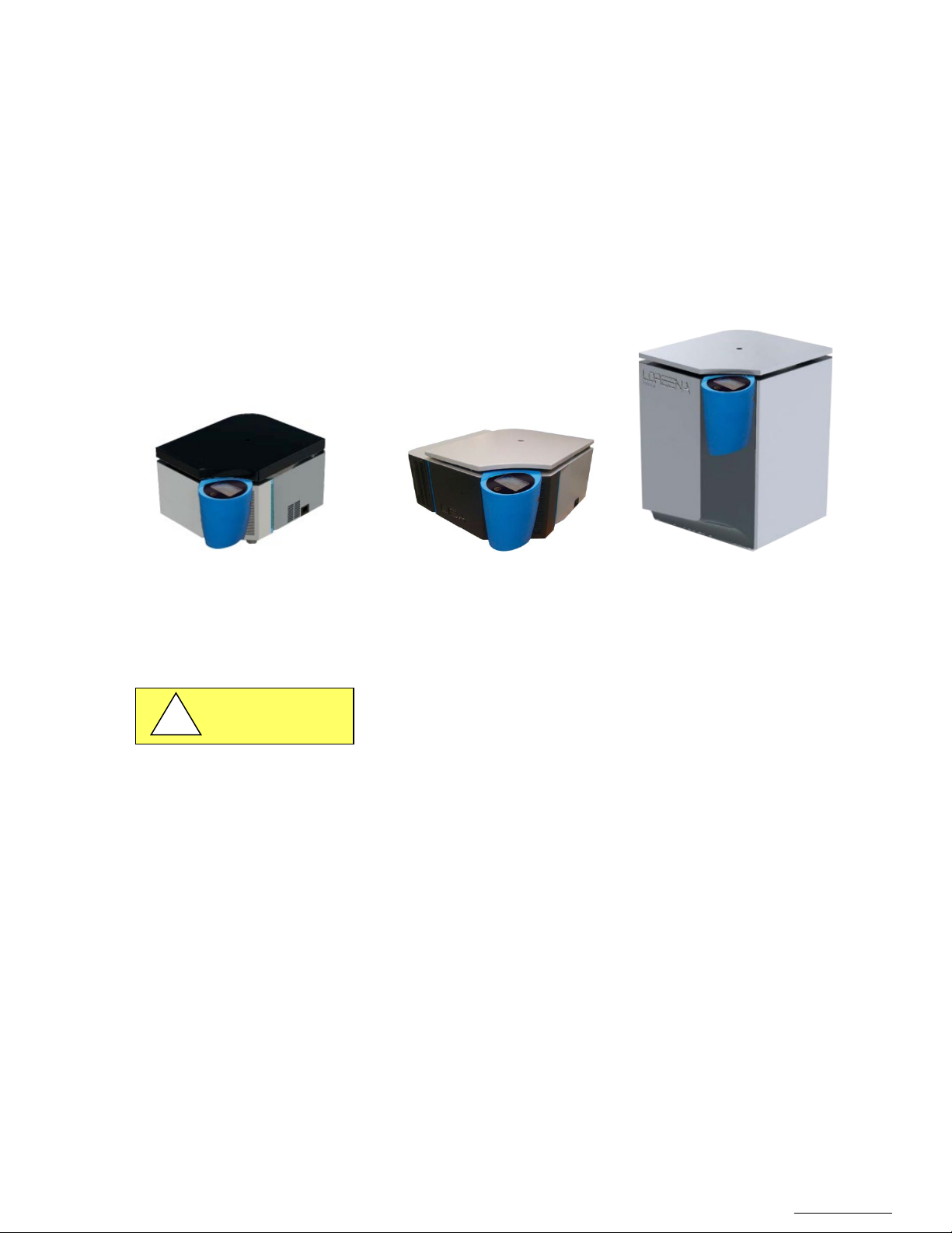
Centrifuges NUWIND 3.0: ventilated and refrigerated models
Intended use
The centrifuge is designed and manufactured for use with rotating accessories supplied by NuAire, Inc. It is suitable for
separating substances of different densities held in suspension, or emulsion in a liquid.
The maximum density of substances should be 1.2 g/ml.
The centrifuge must be used in an optimal state of operation and maintenance. The non-observance of the rule of use may
threaten the health of users or third persons, but it may also cause damages to the unit and/or surrounding equipment.
Users of the equipment must be trained on good centrifugation practices, as well specific usage of the NUWIND models and
Accessories. Any use outside the framework defined above is considered non-compliant.
NuAire, Inc. assumes no responsibility for injury due to improper use.
Page 5
OM0252 | Rev 4 May/2020
Page 5 of 59
NuAire, Inc. | 2100 Fernbrook Lane | Plymouth, MN 55447 | U.S.A | ph: 763.553.1270 | fx: 763.553.0459 | tf: 800.328.3352 | www.nuaire.com
1.2 Safety Instructions
CAUTION
!
The operator must observe the following precautions when using the centrifuge:
• Ensure stability and perfect levelling of the centrifuge.
• Check the correct mounting of the rotor and its accessories before starting a centrifugation cycle.
• Check tube resistance at maximum applied centrifugal force: chemical resistance to centrifuged products and
mechanical strength at the centrifugal force applied thereto.
• Check the condition of the tubes and remove damaged tubes.
• Use only the rotors and accessories authorized by the manufacturer NuAire, Inc.
• Swing-out rotors: install four (or two) buckets; never perform any cycle with missing buckets.
• Maintain and control accessories.
• Balance the load of the rotor around the axis of rotation.
• Respect the maximum density of 1.2 g / ml, in particular in case of a cycle at full speed.
• Limit volume in case of excess density.
• Install the centrifuge in a ventilated area, on a horizontal rigid support to absorb the vibrations generated by the
centrifuge.
• During operation, the centrifuge must not be moved or be subject to impact.
• Do not attempt to open the lid while the rotor is spinning.
• Do not attempt to neutralize the motorized lid lock
• Do not lean over the centrifuge during the spin cycle.
• Do not stay within a space of 10 inch around the centrifuge longer than necessary.
• Do not leave potentially dangerous materials inside the free space.
• Use aerosol-barrier accessories when centrifuging bio hazardous material.
• Condensation may form inside the centrifuge when it is moved from a cold environment to a warm environment.
Allow the centrifuge to warm up for two hours before use.
Prohibitions:
The centrifuge is not designed for the following uses and environments.
The following are prohibited:
• Flammable, explosive, toxic and radioactive materials
• Materials which may react, causing a hazard
• Contaminated materials not contained in an aerosol-barrier container
• Rotating rotors and accessories that have exceeded their maximum use.
• Rotating rotors and accessories that are not maintained according to the instructions in this manual,
or showing signs of wear and/or corrosion.
• Rotating rotors and accessories not supplied by NuAire, Inc.
• Explosive environments
• Radioactive environments
Only operate a centrifuge after taking all necessary safety measures.
Rotors and buckets should be removed from use in case of mechanical fault
trace, or corrosion. These elements have a life cycle duration, engraved on
their visible part: To maintain safe conditions, it is imperative to replace them
when the recommended duration is reached.
Page 6
OM0252 | Rev 4 May/2020
Page 6 of 59
NuAire, Inc. | 2100 Fernbrook Lane | Plymouth, MN 55447 | U.S.A | ph: 763.553.1270 | fx: 763.553.0459 | tf: 800.328.3352 | www.nuaire.com
1.3 Explanation of Symbols
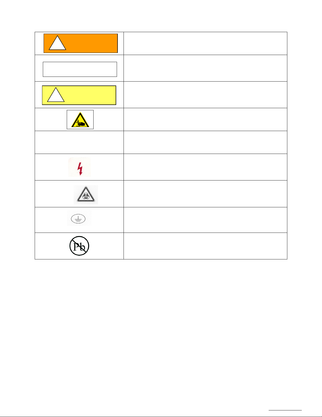
CAUTION
!
CAUTION
WARNING
!
Safety alert symbol indicates a potentially hazardous situation which,
if not avoided, could result in death or serious injury.
CAUTION used without the safety alert symbol indicates a potentially
hazardous situation which, if not avoided, may result in property
damage.
Note:
Safety alert symbol indicates a potentially hazardous situation which,
if not avoided, may result in minor or moderate injury.
Pinching: This warning symbol indicates the presence of a risk of
pinching when handling the lid.
Used for important information
Potential electrical hazard, only qualified person to access
Biohazard
Ground, Earth
Lead Free
Page 7
OM0252 | Rev 4 May/2020
Page 7 of 59
NuAire, Inc. | 2100 Fernbrook Lane | Plymouth, MN 55447 | U.S.A | ph: 763.553.1270 | fx: 763.553.0459 | tf: 800.328.3352 | www.nuaire.com
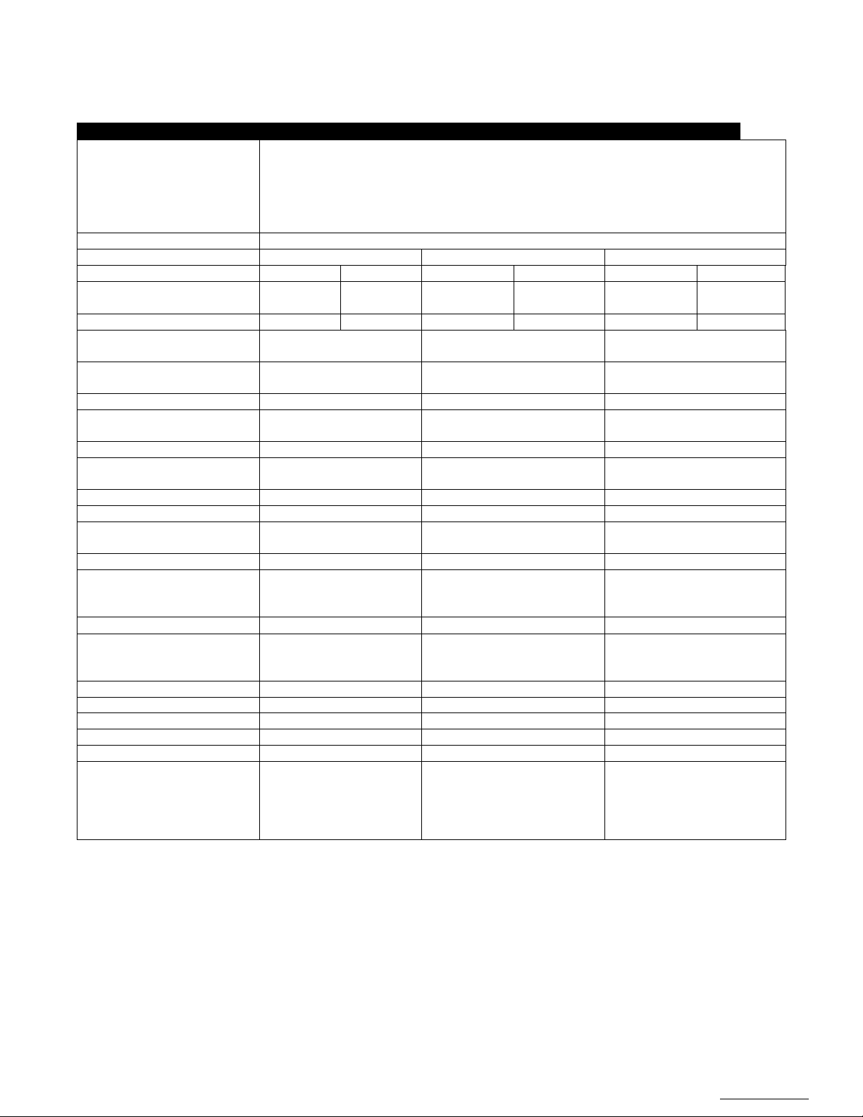
2.0 Models, Specifications and Accessories
Description
Laboratory Centrifuge
Environmental Conditions
For indoor use only
Environment Altitude: 6562 Feet (2000 meters) above sea level
Maximum capacity
4x750 ml x kg / bucket, 4 x buckets
Models
Ventilated
Refrigerated
Refrigerated Floor
Catalog Number
NU- C300V
NU-C300V-E
NU-C300R
NU-C300R-E
NU-C300RF
NU-C300RF-E
Supply Voltage
(Depending on the model)
120 V ± 10%
60 Hz
230 V ± 10%
50Hz
120 V ± 10%
60 Hz
230 V ± 10%
50Hz
120 V ± 10%
60 Hz
230 V ± 10%
50Hz
Nominal intensity (A)
9 A
4 A
17 A
9 A
17 A
9 A
Maximum Speed (rpm)
10,700 rpm NU-RA8-50
(Depending upon the rotor)
12,100 rpm NU-RA8-50
(Depending upon the rotor)
12,100 rpm NU-RA8-50
(Depending upon the rotor)
Maximum Relative
Centrifugal Force (g)
Total Power Consumed
1000 Watt
1700 Watt
1700 Watt
Dissipated Heat (BTU/h)
(1 BTU/h = 0.29307 W)
Fluid Coolant / Charge
Not applicable
R404A / 0.35 kg
R404A / 0.35 kg
Ambient Operating
Temperature
Temperature adjustment range
N/A
-10 ° C to 40 ° C
-10 ° C to 40 ° C
Temperature control precision
N/A
± 2 ° C
± 2 ° C
Dimensions on bench
(H x W x D)
37 x 50 x 66 cm
14.6 x 19.7 x 26 inches
35 x 77 x 68 cm
13.8 x 30.3 x 26.8 inches
83 x 67 x 69 cm
32.7 x 26.4 x 27.2 inches
Net weight (excluding rotor)
82 kg /180 lbs.
145 kg / 320lbs.
170 kg / 375lbs.
Packing (H x W x D) / Weight
54 x 74 x 77 cm
97 kg / 215 lbs.
54 x 90 x 80 cm
160kg / 350 lbs.
100 x 80 x 80 cm
185kg / 410 lbs.
Maximum sound level
≤61 dB(A)
≤ 60 dB(A)
≤ 57 dB(A)
Integrated systems
Imbalance detection sensor
Rotor speed control
Imbalance detection sensor
Rotor speed control
Imbalance detection sensor
Rotor speed control
Control System
Microprocessor
Microprocessor
Microprocessor
Acceleration slopes
9 9 9
Braking slopes
10
10
10
Speed control precision
± 10 rpm
± 10 rpm
± 10 rpm
Number of programs
99
99 + Pre-cooling + Pre-warming
99 + Pre-cooling + Pre-warming
Optimal settings refrigeration
N/A
+4 ° C temperature with
20⁰C ± 2⁰C.
+4 ° C temperature with
20⁰C ± 2⁰C.
2.1 Specifications
Environment Temperature Range: : 60⁰F - 85⁰F (15⁰C - 30⁰C)
Environment Humidity: Maximum relative humidity 80% for
temperatures up to 31⁰C decreasing
linearly to 50% relative humidity at 40⁰C
13,000 xg 16,660 xg 16,660 xg
3413 BTU/h 5801 BTU/h 5801 BTU/h
20⁰C ± 2⁰C 20⁰C ± 2⁰C 20⁰C ± 2⁰C
21.3 x 29.1 x 30.3 / inches
Motorized lid lock
21.3 x 35.4 x 31.5 inches
Motorized lid lock
NU-RX750 rotor can be
maintained at 3,600RPM at an
ambient temperature of
39.4 x 31.5 x 31.5 inches
Motorized lid lock
NU-RX750 rotor can be
maintained at 3,600RPM at an
ambient temperature of
Page 8

OM0252 | Rev 4 May/2020
Page 8 of 59
NuAire, Inc. | 2100 Fernbrook Lane | Plymouth, MN 55447 | U.S.A | ph: 763.553.1270 | fx: 763.553.0459 | tf: 800.328.3352 | www.nuaire.com
2.2 Accessories
References
Description
Lot
NU-RX1000
Swing-Out rotor 4x 1000 ml
One Unit
NU-B1000
1000 ml buckets
Set of 4
NU-L1000
Lid 1000 ml
Set of 4
NU-BXDW4
Microplates carriers
Set of 2 or 4
NU-4T2
1,5 - 2ml MicroTube
Set of 2 or 4
NU-4T5
Tube insert 50x 5 ml
Set of 2 or 4
NU-4T10
Tube insert 39x 10 ml
Set of 2 or 4
NU-4T15C
Conical tube insert 24 x 15 ml
Set of 2 or 4
NU-4T50C
Conical tube insert 10 x 50 ml
Set of 2 or 4
NU-2T200C
2 x 175/225* ml Conical Bottle
Set of 2 or 4
NU-4T250C
2 x 250* ml Conical Bottle
Set of 2 or 4
NU-4T290F
2 x 290* ml Flat Bottle
Set of 2 or 4
NU-4T500C
1 x 500* ml conical bottle
Set of 2 or 4
NU-4T265
1 x 625 ml Flat Bottle
Set of 2 or 4
NU-4T750
1 x 750 ml Flat Bottle
Set of 2 or 4
NU-RX750
Swing-Out rotor 4x 750 ml (3 liters)
One unit
NU-B750
750 ml buckets
Set of 4
NU-L750
Lid 750 ml
Set of 4
NU-3T2
1,5 - 2ml MicroTube
Set of 2 or 4
NU-3T5
Tube insert 27x 5 ml
Set of 2 or 4
NU-3T10
Tube insert 21x 10 ml
Set of 2 or 4
NU-3T15C
Conical tube insert 14 x 15 ml
Set of 2 or 4
NU-3T50CL
Conical tube insert 6 x 50 ml
Set of 2 or 4
NU-3T50C*
Conical tube insert 7 x 50 ml
Set of 2 or 4
NU-3T50S
Self-standing conical tube insert 5 x 50 ml
Set of 2 or 4
NU-3T200C
175/225* ml Conical Bottle
Set of 2 or 4
NU-3T500C
500* ml Conical Bottle
Set of 2 or 4
NU-3T750
Flat bottom bottle 1x 750mL
Set of 2 or 4
NU-BXDW
Microplate Bucket X
Set of 4
NU-RHDW
Microplate Rotor H
One unit
NU-BHDW
Microplate Bucket H
Set of 2
NU-RA6-100
6x 100 ml 28° angle rotor
One unit
NU-RA8-50
8x 50 ml 25° angle rotor
One unit
NU-RA16-5
16x 5 ml 45° angle rotor
One unit
NU-RA48-2
48x 2 ml 45° angle rotor
One unit
NU-RA30-2
30x 2 ml 45° angle rotor
One unit
(*) these inserts cannot be used with Bio-containment lids
Page 9

OM0252 | Rev 4 May/2020
Page 9 of 59
NuAire, Inc. | 2100 Fernbrook Lane | Plymouth, MN 55447 | U.S.A | ph: 763.553.1270 | fx: 763.553.0459 | tf: 800.328.3352 | www.nuaire.com
3.0 Warranty
NuAire, Inc. warrants NU-C300 Series NUWIND Centrifuge that it will repair F.O.B. its factory or furnish without charge
F.O.B. its factory a similar part to replace any material in its equipment within 60 months after the date of sale if proved to
the satisfaction of the company to have been defective at the time it was sold provided that all parts claimed defective shall
be returned, properly identified to the company at its factory, charges prepaid. Factory installed equipment or accessories
are warranted only to the extent guaranteed by the original manufacturer, and this warranty shall not apply to any portion
of the equipment modified by the user. Claims under this warranty should be directed to NuAire, Inc. setting forth in detail
the nature of the defect, the date of the initial installation and the serial and model number of the equipment.
This warranty shall not apply to any NuAire product or part thereof which has been subject to misuse, abuse, accident,
shipping damage, improper installation or service, or damage by fire, flood or acts of God. If the serial number of this
product is altered, removed or defaced as to be illegible, the Warranty shall be null and void in its entirety.
The warranty is for the sole benefit of the original purchaser and is not assignable or transferable. Prior to returning any
item, for any reason, contact NuAire for a Return Authorization Number. This number must accompany all returns. Any
product shipped to NuAire without this number will be returned refused shipment or collect freight.
4.0 Shipments
NuAire takes every reasonable precaution to assure that your NUWIND Centrifuge arrives without damage. Motor carriers
are carefully selected and shipping cartons have been specially designed to insure your purchase. However, damage can
occur in any shipment and the following outlines the steps you should take on receipt of a NuAire NUWIND Centrifuge to be
sure that if damage has occurred, the proper claims and actions are taken immediately.
4.1 Damaged Shipments
4.1.1 Terms are factory, unless stated otherwise. Therefore, it is important to check each shipment before acceptance.
4.1.2 If there is visible damage, the material can be accepted after the driver makes a notation on the consignee's copy
of the freight bill. Then an inspection must be made to verify the claim against the carrier. This inspection is the
basis of your filing the claim against the carrier.
4.1.3 If concealed damage is found it is absolutely necessary to NOTIFY THE FREIGHT AGENT AT ONCE and request an
inspection. Without this inspection, the transportation company may not accept a claim for loss or damage. If the
carrier will not perform the inspection, an affidavit must be prepared stating that he was contacted on a certain
date and that he failed to comply with the request. This along with other papers in the customer's possession will
support the claim.
Page 10
OM0252 | Rev 4 May/2020
Page 10 of 59
NuAire, Inc. | 2100 Fernbrook Lane | Plymouth, MN 55447 | U.S.A | ph: 763.553.1270 | fx: 763.553.0459 | tf: 800.328.3352 | www.nuaire.com
5.0 Installation Instructions
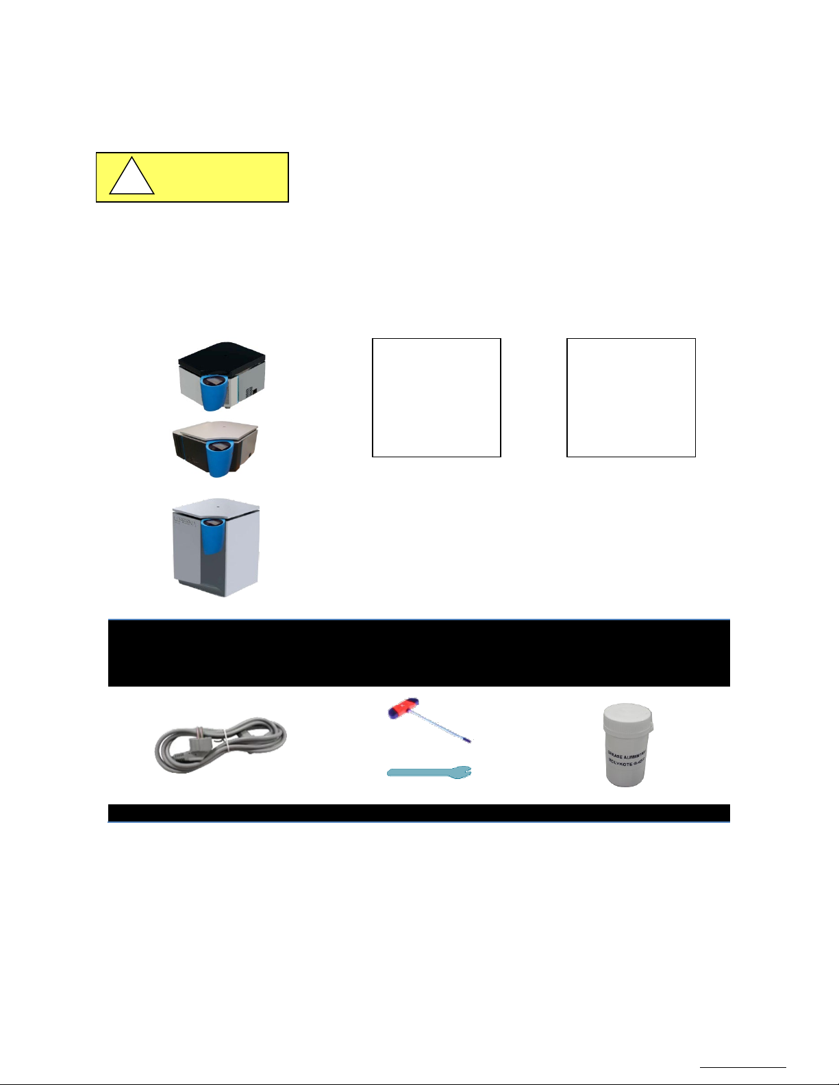
NUWIND 3.0 Centrifuge Model
3) Refrigerated Floor Standing
Power Cord
Manual release key
Food grade grease
CAUTION
!
5.1 Handling and transport
The package containing the centrifuge needs to be handled by suitable means (pallet truck, etc.).
Please ensure that the people in charge of handling are qualified to handle the lifting equipment.
Maintain the following conditions during transport:
• Temperature: -20 to 50 ° C
• Relative humidity: <90%, under the dew point
5.2 Unpacking
Remove the cardboard packaging made of 2 parts (a lid and a bottom).
The NUWIND centrifuge was packed with great care to prevent transport hazards. Before disposing of the packaging of the
centrifuge, and its spinning accessories, please make sure you are in possession of the following:
5.2.1 Packing list
Declaration
1) or
2)
or
3)
1) Ventilated Benchtop or
2) Refrigerated Benchtop or
Compliance Certificate User Manual (Flash Drive)
Of
Conformity
or
NUWIND
Centrifuge
Operation and
Maintenance
Manual
Page 11
OM0252 | Rev 4 May/2020
Page 11 of 59
NuAire, Inc. | 2100 Fernbrook Lane | Plymouth, MN 55447 | U.S.A | ph: 763.553.1270 | fx: 763.553.0459 | tf: 800.328.3352 | www.nuaire.com
5.2.2 Preparation of rotor and accessories
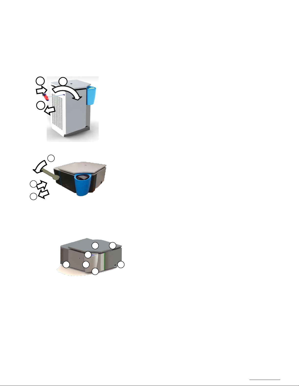
1. Insert the allen wrench in the hole on the left side panel to manually
sitting at the bottom
1. Insert the release key into the hole in the front
is
1 2 3
2 1 3
2
1 3 5 4 7
6
The rotor and the 4 buckets may have been packed inside the centrifuge in order to reduce the volume of packing
material. However, before any utilization, make sure to remove the packing foam before turning the unit on for the
first time.
These packing foams allow the rotor to be centered inside the bowl without any constraint or forces applied directly
on the motor shaft or without damaging any internal part in the bowl.
open the centrifuge
2. Turn it clockwise until the lid opens up
3. Remove the allen wrench from the hole
4. Remove all the packing foam inside the bowl
5. Remove the buckets and put them on a table next to the centrifuge
6. Remove the rotor with both hands and put it on a table
(it shouldn’t be locked on the shaft) next to the centrifuge
7. Remove all the different layers of packing foam
8. If needed, clean the bowl if any residual packing material or dust is
5.2.3 Description
2.Turn down until the lid opens up
3.Remove the key from the hole
4. Remove all the packing foam inside the bowl
5. Remove the buckets and put them on a table next to the centrifuge
6. Remove the rotor with both hands and put it on a table
(it shouldn’t be locked on the shaft) next to the centrifuge
7. Remove all the different layers of packing foam
8. If needed, clean the bowl if any residual packing material or dust
sitting at the bottom
1. Lid
2. Window
3. Control panel
4. Electronic warhead
5. Main switch
6. Cooling unit (refrigerated model only)
7. Electrical outlet
Page 12
OM0252 | Rev 4 May/2020
Page 12 of 59
NuAire, Inc. | 2100 Fernbrook Lane | Plymouth, MN 55447 | U.S.A | ph: 763.553.1270 | fx: 763.553.0459 | tf: 800.328.3352 | www.nuaire.com
5.3 Site preparation
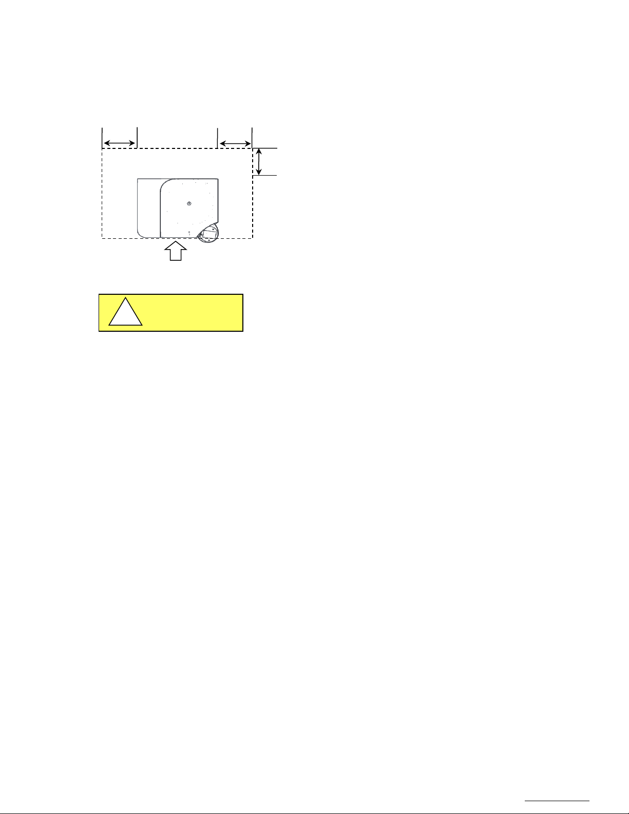
10”
10”
Access area
10”
CAUTION
!
Prepare a stable, clean and levelled support (e.g. laboratory bench). This support must be able to support the weight of the
centrifuge and its use, and be firm enough so as not to generate or maintain vibration. Such vibrations would degrade the
results of the centrifugation, and may result in an unbalanced error.
A clearance of 10 inch (250mm) around the centrifuge should be
arranged according to IEC 61010-2-020: No potentially hazardous
material, nobody or no object shall be deposited within the free
space.
Open space around the centrifuge
It is recommended that no less than two people are present to manually lift the centrifuge onto the laboratory bench.
5.4 Electrical environment
The centrifuge requires must be 230V/50Hz or 120V/60Hz, single phase, (current rating varies per centrifuge model,
reference Electrical/Environmental Requirements).according to the manufacturer sheet on the back of the unit.
The centrifuge must be plugged into an outlet with protective earthing connection with the standard power cord.
The electrical outlet into which the centrifuge is connected should be readily accessible for maintenance purposes.
Do not position the centrifuge to prevent access to the power cord.
The power cord plug serves as the disconnect and should remain readily accessible. The electrical outlet should be on its
own branch circuit, protected with a circuit breaker at the distribution panel near the centrifuge.
Page 13
OM0252 | Rev 4 May/2020
Page 13 of 59
NuAire, Inc. | 2100 Fernbrook Lane | Plymouth, MN 55447 | U.S.A | ph: 763.553.1270 | fx: 763.553.0459 | tf: 800.328.3352 | www.nuaire.com
6.0 Operating the NU-C300
6.1 First Start / Powering
The first start must fulfill the conditions of the IEC 61010-2-020 safety standard
Page 14
OM0252 | Rev 4 May/2020
Page 14 of 59
NuAire, Inc. | 2100 Fernbrook Lane | Plymouth, MN 55447 | U.S.A | ph: 763.553.1270 | fx: 763.553.0459 | tf: 800.328.3352 | www.nuaire.com
6.1.1 Rotor assembly
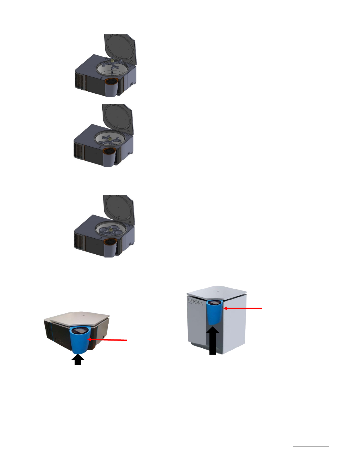
Lid Open Switch
Lid Open Switch
On/Off Switch position
On/Off Switch position
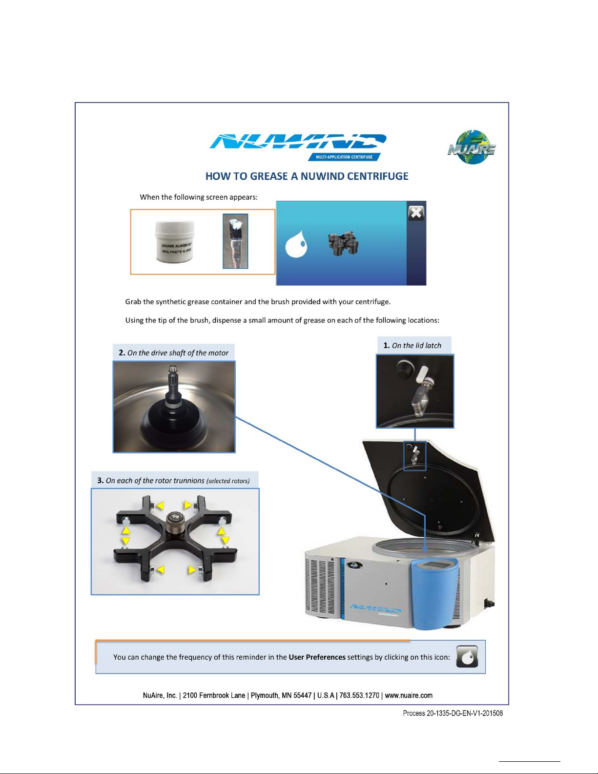
1. Clean and lubricate the motor shaft by depositing a thin film
of the food grade grease supplied.
2. Place the rotor above the drive shaft.
3. Slide the rotor on the drive shaft.
4. A click indicates that the rotor is locked.
5. Clean and lubricate the pins by depositing a thin film of the
food grease supplied.
6.1.2 Position the buckets
Swing-out rotors are used with round buckets or micro titration buckets.
1. Place the buckets in the corresponding numbered locations.
6.1.3 First powering
Activate the switch on the bottom right of the control center.
Under Control Center
Under Control Center
Page 15
OM0252 | Rev 4 May/2020
Page 15 of 59
NuAire, Inc. | 2100 Fernbrook Lane | Plymouth, MN 55447 | U.S.A | ph: 763.553.1270 | fx: 763.553.0459 | tf: 800.328.3352 | www.nuaire.com
6.1.4 Using the interface
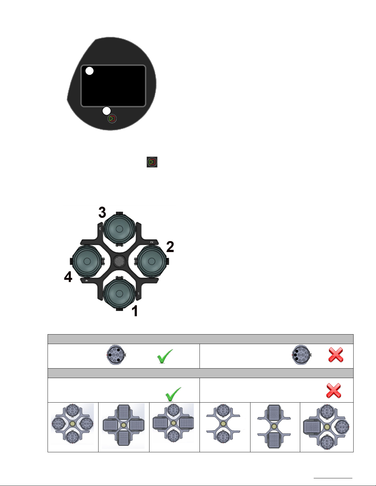
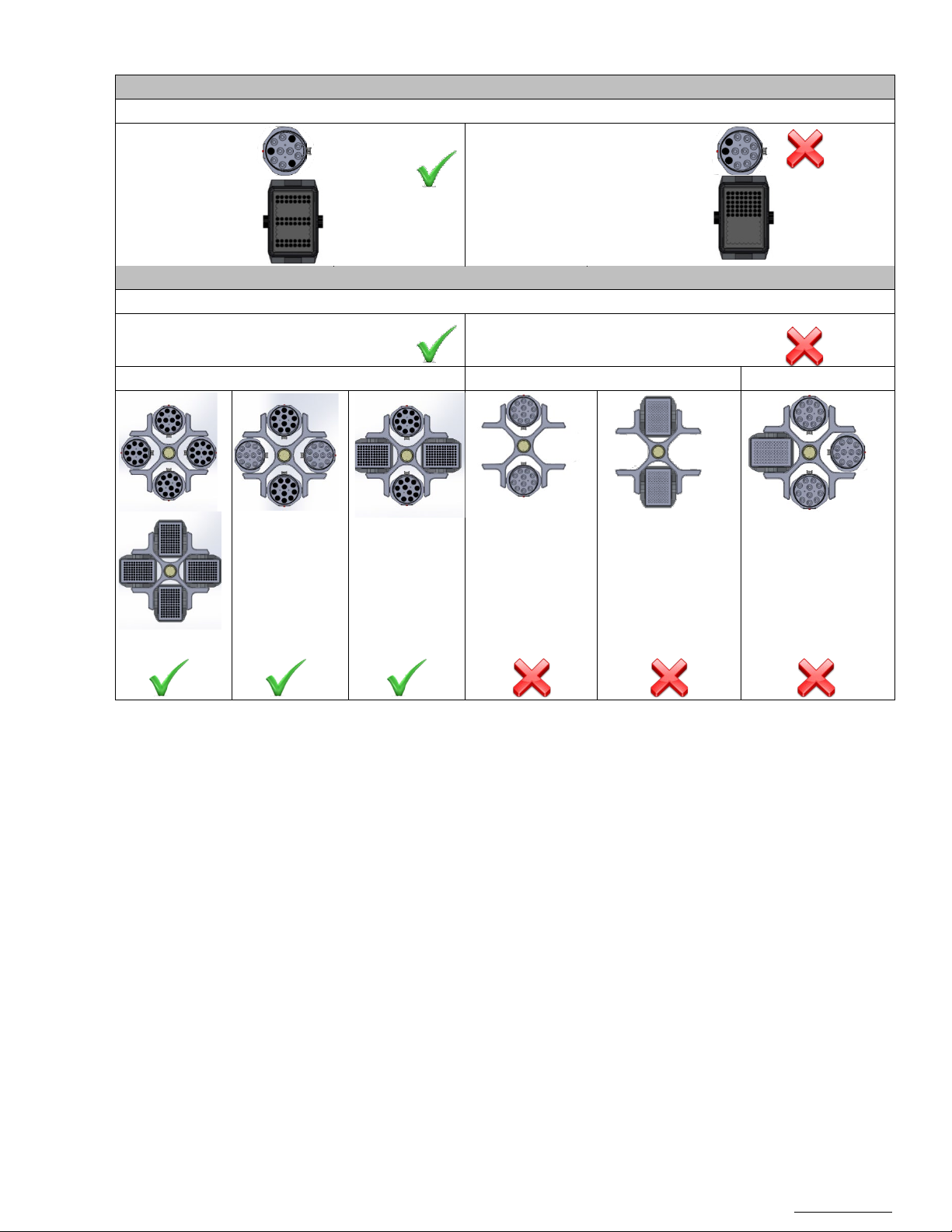
Position the 4 numbered buckets in their corresponding positions
and/or the centrifuge.
Loading the buckets
Loading the rotor
Forbidden:
Asymmetrical loading
2
1
1. Touch screen for direct access to various functions.
2. Single button for easy operation.
This button allows the validation, the start of a cycle, but also
the interruption of a cycle, and the output of a menu.
The functions accessible through this single button are
activated as required by the microcontroller.
6.1.5 Opening the lid
On the first start, the lid may not open right away due to a long storage in a cold environment.
In this case, warm-up the jacks by repeated manual shifting of the lid downwards.
To open the lid, press the button .
6.1.6 Rotor loading and balancing
Allowed:
on the rotor. Each bucket should pivot freely in its slot.
Place the inserts corresponding to the tubes to be centrifuged in
the four buckets
The buckets must be symmetrically distributed.
For better balance, each numbered bucket must be placed in the
corresponding position marked on the rotor.
Each position on the rotor must be equipped with its bucket.
Do not use a rotor without its complete set of four buckets.
Maximum loads according to the type of rotor are specified in the
annex.
The centrifuge tolerates an imbalance of 15grams.
If the imbalance is higher than the tolerated threshold, an
imbalance detection system stops the centrifuge automatically.
The following message appears: "Imbalance" and the rotor stops
in free wheel mode without braking system.
Excessive imbalance is likely to damage the turning components
Forbidden :
Allowed:
Symmetrical loading
Incomplete loading
Page 16
OM0252 | Rev 4 May/2020
Page 16 of 59
NuAire, Inc. | 2100 Fernbrook Lane | Plymouth, MN 55447 | U.S.A | ph: 763.553.1270 | fx: 763.553.0459 | tf: 800.328.3352 | www.nuaire.com
6.1.7 Quick start-up
Before using the centrifuge, make sure it has been properly installed.
6.2 Operating
6.2.1 Settings
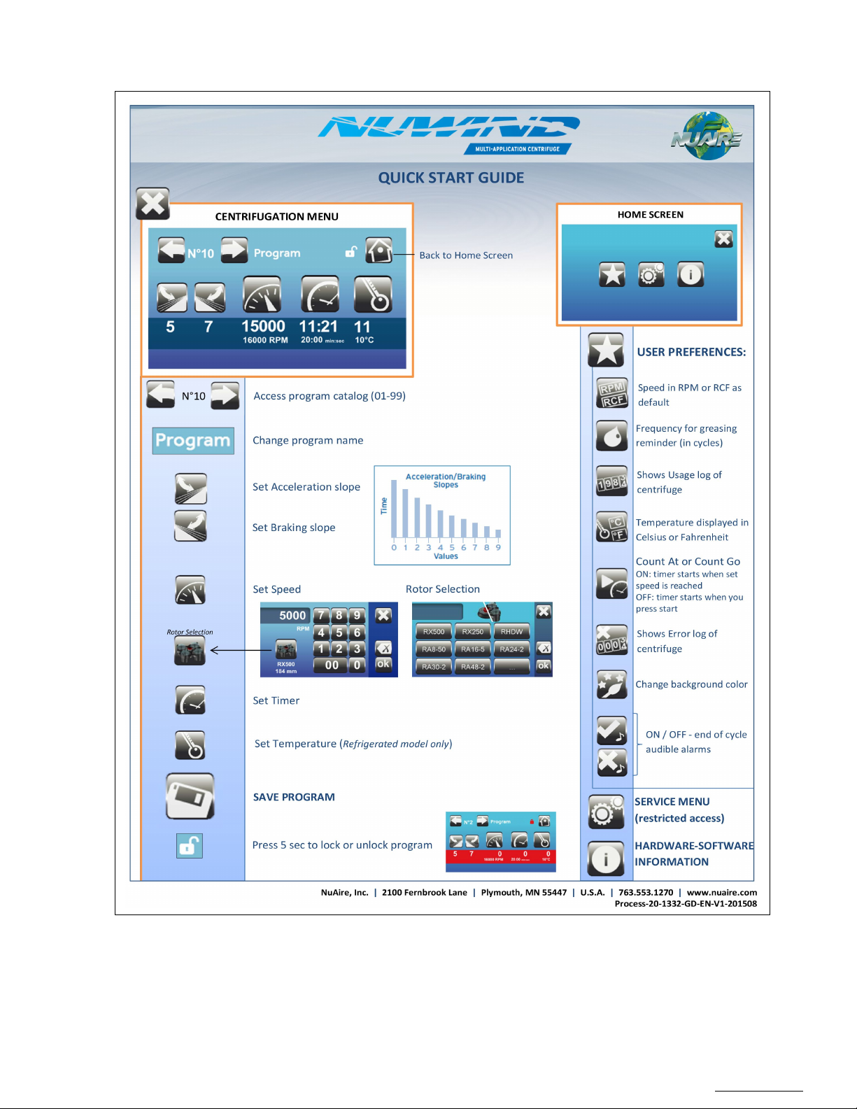
This section is accessible through the Admin section. It allows the creation and/or modification of a program and the
customization of the centrifuge.
Page 17
OM0252 | Rev 4 May/2020
Page 17 of 59
NuAire, Inc. | 2100 Fernbrook Lane | Plymouth, MN 55447 | U.S.A | ph: 763.553.1270 | fx: 763.553.0459 | tf: 800.328.3352 | www.nuaire.com
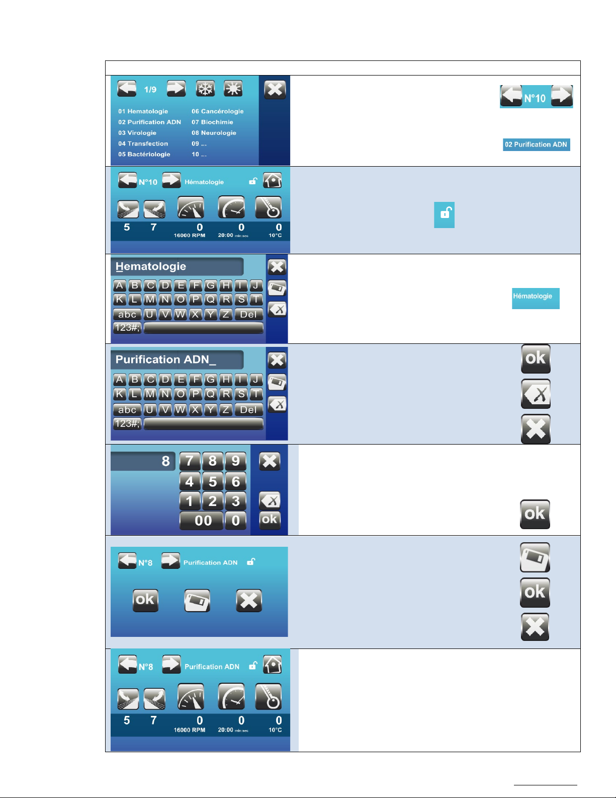
6.2.2 Create / edit a program name
Visual
Instruction
Control
Enter the new title
Select the program to create/edit
Note: 99 programs are available,
from 01 to 99.
The program can be modified when the
protection icon is an open lock:
Edit the title screen by pressing on the title.
Save the new title by pressing "ok".
Note:
To delete the entire text:
To exit the menu without saving changes:
Enter the program number you wish to
create
Validate
Confirm saving
Note:
Accept without saving changes:
Exit without saving changes:
The program has been saved.
(The lock is not activated).
Page 18
OM0252 | Rev 4 May/2020
Page 18 of 59
NuAire, Inc. | 2100 Fernbrook Lane | Plymouth, MN 55447 | U.S.A | ph: 763.553.1270 | fx: 763.553.0459 | tf: 800.328.3352 | www.nuaire.com
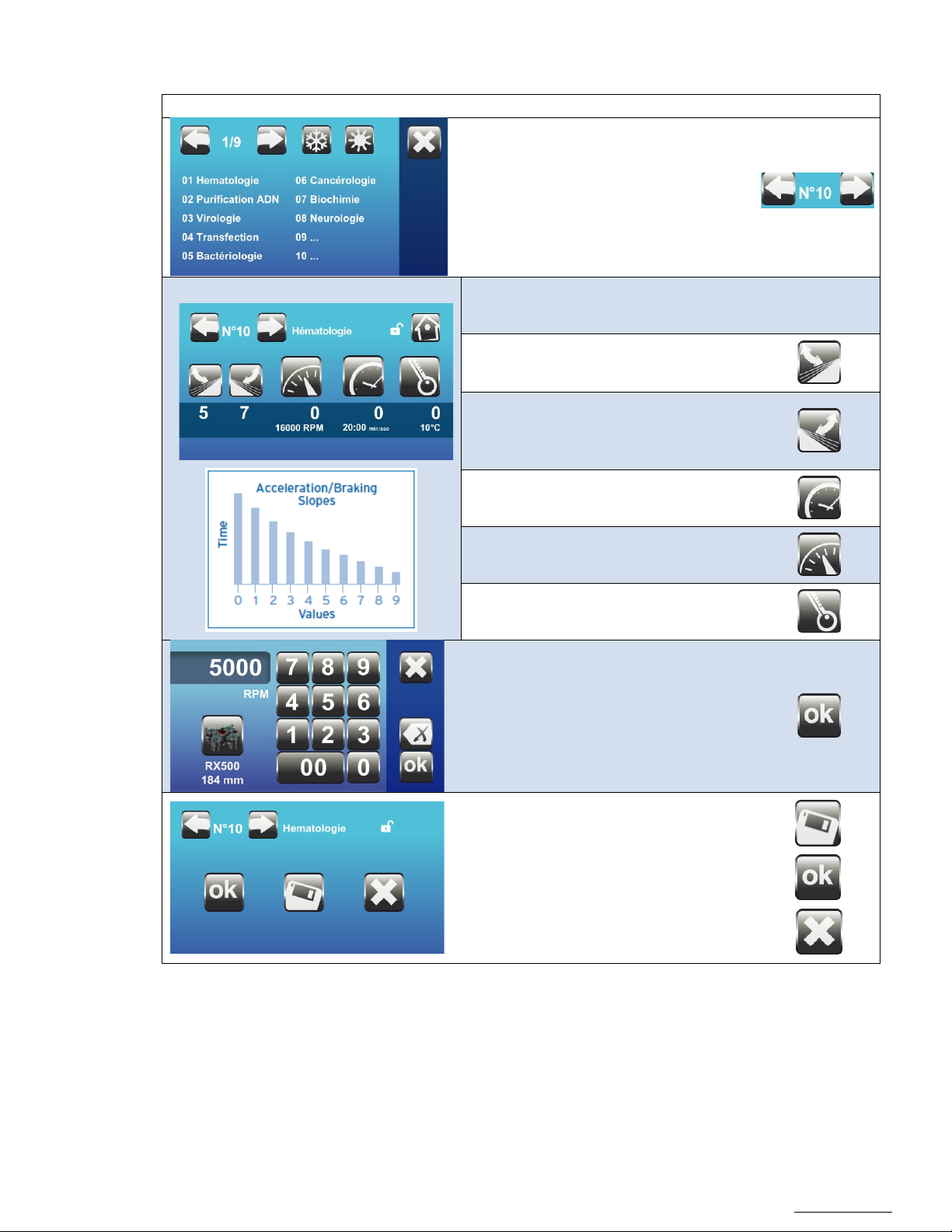
6.2.3 Set program settings
Visual
Instruction
Control
9: fastest acceleration
9: fastest deceleration
Select the program to edit
Select the desired parameter by pressing
the icon:
1: slowest acceleration
0: no braking at all
1: slowest deceleration
Centrifuge speed (in RPM or RCF)
Cycle time
Setpoint temperature (only on the
refrigerated model)
Change the value (e.g. speed).
Confirm
Confirm settings
Note: Submit without saving any changes in
the program:
Exit without saving changes:
Page 19
OM0252 | Rev 4 May/2020
Page 19 of 59
NuAire, Inc. | 2100 Fernbrook Lane | Plymouth, MN 55447 | U.S.A | ph: 763.553.1270 | fx: 763.553.0459 | tf: 800.328.3352 | www.nuaire.com
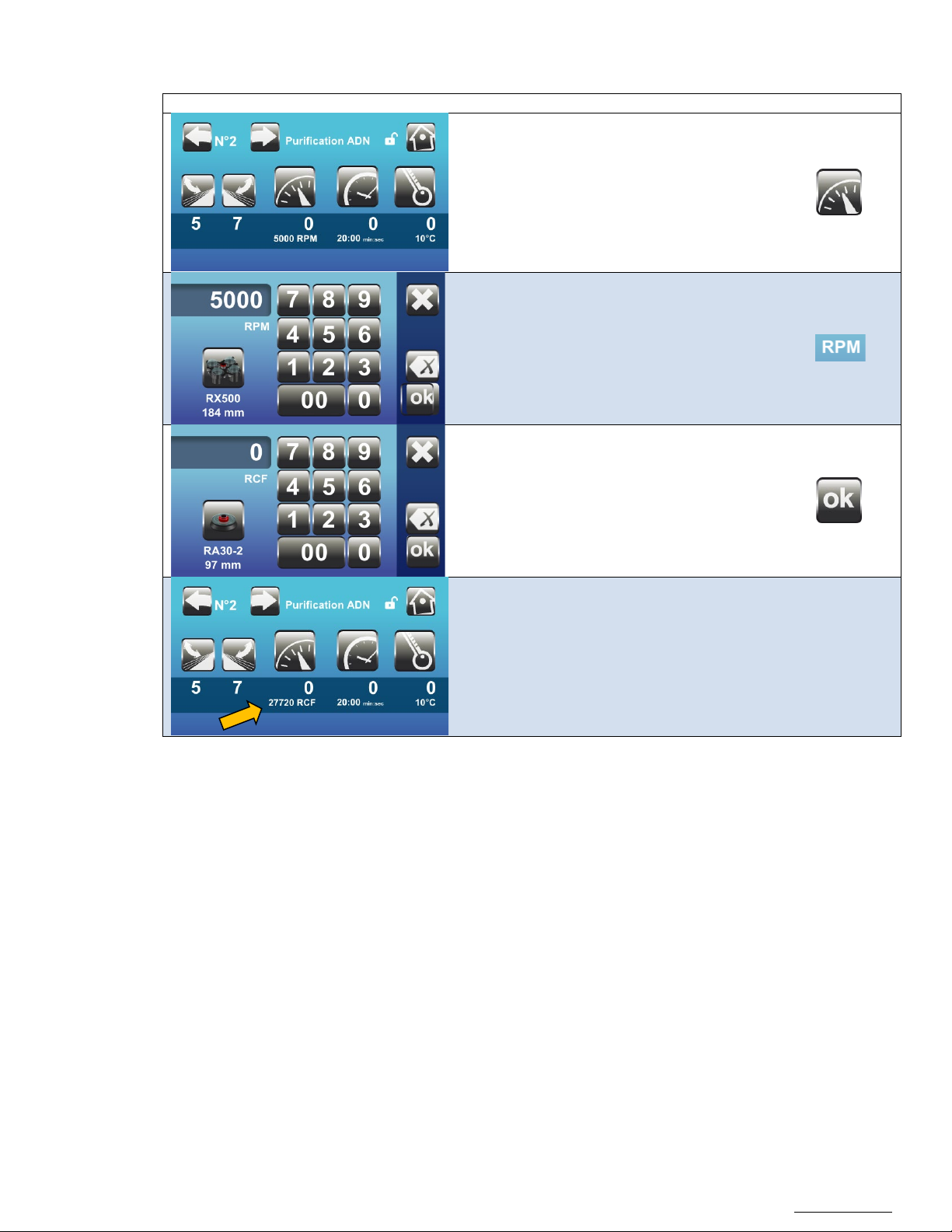
6.2.4 Set speed in RPM or RCF
Visual
Instruction
Control
Access the speed setting key
Press on the icon RPM to modify the unit from
RPM to RCF.
Enter the RCF (g) value desired,
Confirm
Note: The rotor name and radius will be
Displayed below the picture of the rotor.
The program will now display the RCF value (g).
Page 20
OM0252 | Rev 4 May/2020
Page 20 of 59
NuAire, Inc. | 2100 Fernbrook Lane | Plymouth, MN 55447 | U.S.A | ph: 763.553.1270 | fx: 763.553.0459 | tf: 800.328.3352 | www.nuaire.com
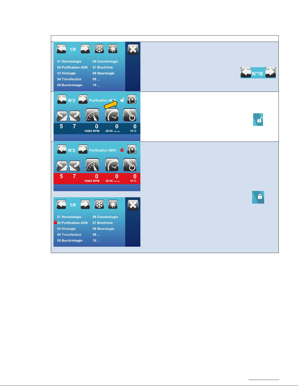
6.2.5 Protect the settings of a program
Visual
Instruction
Control
From an Admin profile, a program can be locked to prevent any modifications of the settings
Select the program to lock
Press on the open lock for 4 seconds.
The lock is now closed.
The program is now protected.
Note: To remove the protection, enter the
program through an Admin user
profile and press on the closed lock
for 3 seconds.
It will then re-open. You are now
able to modify the program.
In the list of programs, a lock appears in
front of the program
Page 21
OM0252 | Rev 4 May/2020
Page 21 of 59
NuAire, Inc. | 2100 Fernbrook Lane | Plymouth, MN 55447 | U.S.A | ph: 763.553.1270 | fx: 763.553.0459 | tf: 800.328.3352 | www.nuaire.com
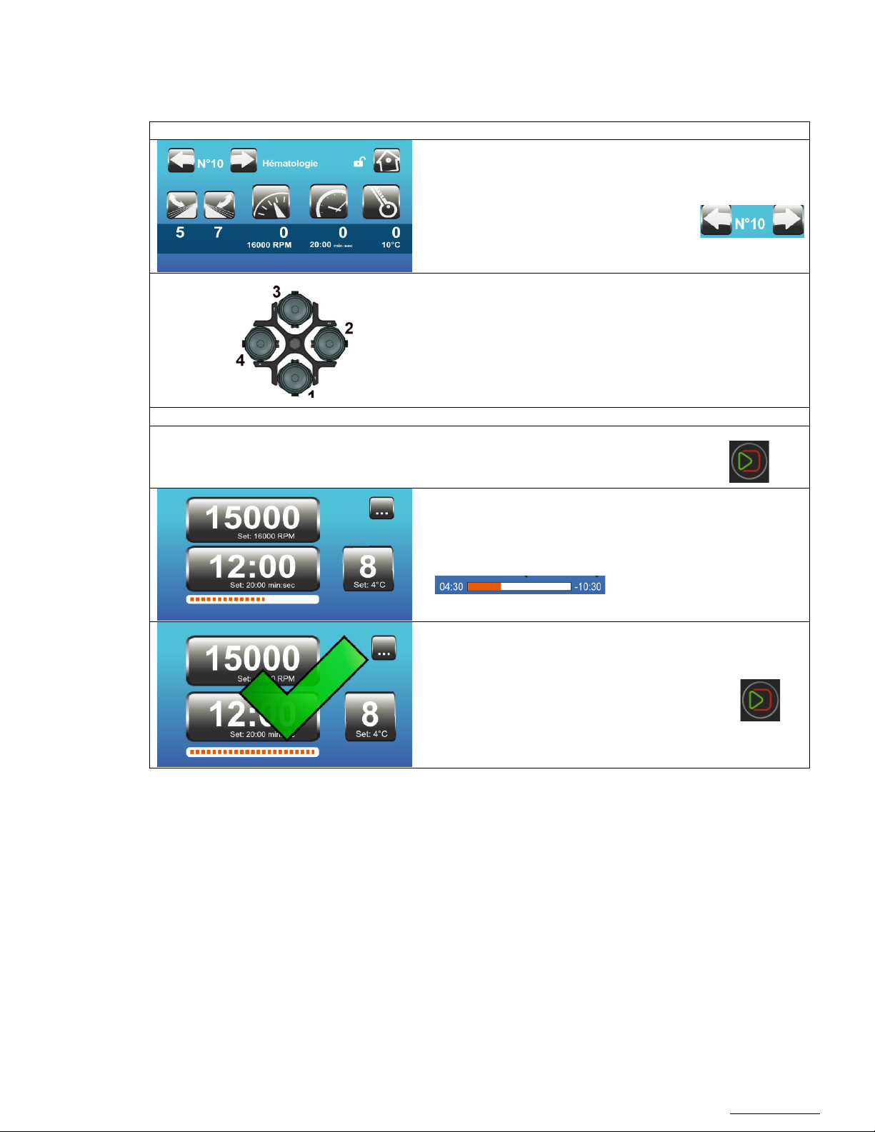
6.2.6 Centrifuge: Use a program
Visual
Instruction
Control
Close the lid
Turn on the centrifuge. The switch is in the lower right portion.
Any user can access a program (user, admin, service tech)
Select the program you want to use
Load the rotor and buckets as instructed in
6.1.6
Start the cycle
Centrifugation starts.
The progression bar appears
Open the lid when finished
Remove the tubes.
Page 22
OM0252 | Rev 4 May/2020
Page 22 of 59
NuAire, Inc. | 2100 Fernbrook Lane | Plymouth, MN 55447 | U.S.A | ph: 763.553.1270 | fx: 763.553.0459 | tf: 800.328.3352 | www.nuaire.com
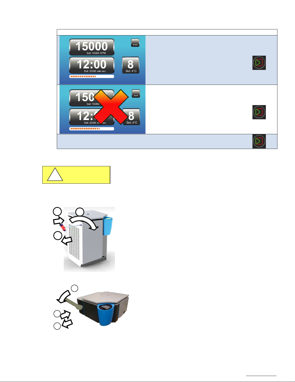
6.2.7 Interrupt centrifugation
Visual
Instruction
Control
This operation must be performed by a person trained in centrifugation-
1. Switch off the power to the unit
2 1 3
1
2
3
CAUTION
!
During a centrifugation, press the Start/Stop
button.
The rotor will start slowing down until
complete stop
Open the lid.
6.2.8 Open after an electric power failure / Emergency Stop
related risks.
In case of power failure, the lid cannot be opened by the engine unlocking
control.
You must wait 15 minutes for the rotor to come to a complete stop before
opening manually.
2. Insert the unlocking key into the hole on the left side panel
3. Turn it until the lid opens up
4. Remove the key
5. Recover the samples
Page 23
OM0252 | Rev 4 May/2020
Page 23 of 59
NuAire, Inc. | 2100 Fernbrook Lane | Plymouth, MN 55447 | U.S.A | ph: 763.553.1270 | fx: 763.553.0459 | tf: 800.328.3352 | www.nuaire.com
Following a manual release, the wrench must be removed from its housing to prevent accidents related to the rotation of the
Visual
Instruction
Control
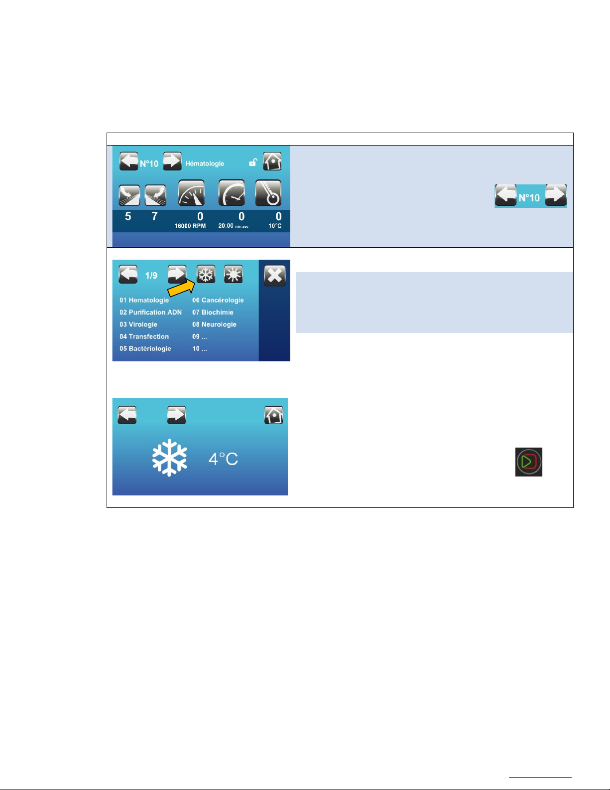
Select the pre-cooling program:
Rotor: Standard Precool
This program is set to cool the centrifuge
cannot be modified.
Air: Smart Precool
This program is set to cool the centrifuge
will stop when the temperature is reached.
wrench during the activation of the locking mechanism. In addition, the security indicator label must be replaced during a safety
check carried out by an authorized technician.
6.2.9 Precooling
On the Refrigerated model, a "Pre-cooling" cycle prior to centrifugation allows to cool the centrifuge down to
4 degrees Celsius so it is ready for temperature sensitive samples.
Access to the list of programs by pressing
this icon :
and accessories down to 4°C during a 22
minute cycle at 2500 RPM. Acceleration and
Deceleration slope are both set on 9 and
until the probe temperature reaches 4⁰C and
*Select Rotor or Air in user preferences
Start the cycle by pressing
The temperature inside the bowl will show
on the display
Page 24
OM0252 | Rev 4 May/2020
Page 24 of 59
NuAire, Inc. | 2100 Fernbrook Lane | Plymouth, MN 55447 | U.S.A | ph: 763.553.1270 | fx: 763.553.0459 | tf: 800.328.3352 | www.nuaire.com
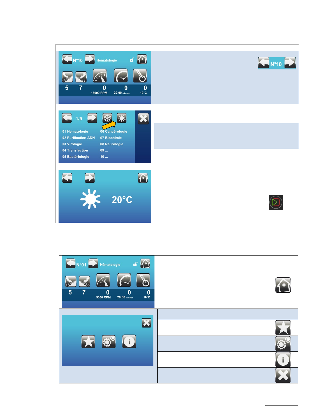
6.2.10 Prewarming
Visual
Instruction
Control
This program is set to warm the centrifuge
are both set on 9 and cannot be modified.
Visual
Instruction
Control
On the Refrigerated model, a "Pre-warming" cycle prior to centrifugation allows to warm the centrifuge so it is
ready for a protocol at ambient temperature or warmer (especially after a cycle at a colder temperature).
Access to the list of programs by pressing
this icon :
Select the pre-warming program:
up to 20°C during a 20min cycle at 5,100
RPM. Acceleration and Deceleration slope
Start the cycle by pressing
The temperature inside the bowl will show
on the display
6.2.11 Other menus
Access to other menus by pressing :
Select the menu
• User Preferences
• Service menu
• Information
• Go back to the centrifugation screen.
Page 25
OM0252 | Rev 4 May/2020
Page 25 of 59
NuAire, Inc. | 2100 Fernbrook Lane | Plymouth, MN 55447 | U.S.A | ph: 763.553.1270 | fx: 763.553.0459 | tf: 800.328.3352 | www.nuaire.com
Visual
Instruction
Control
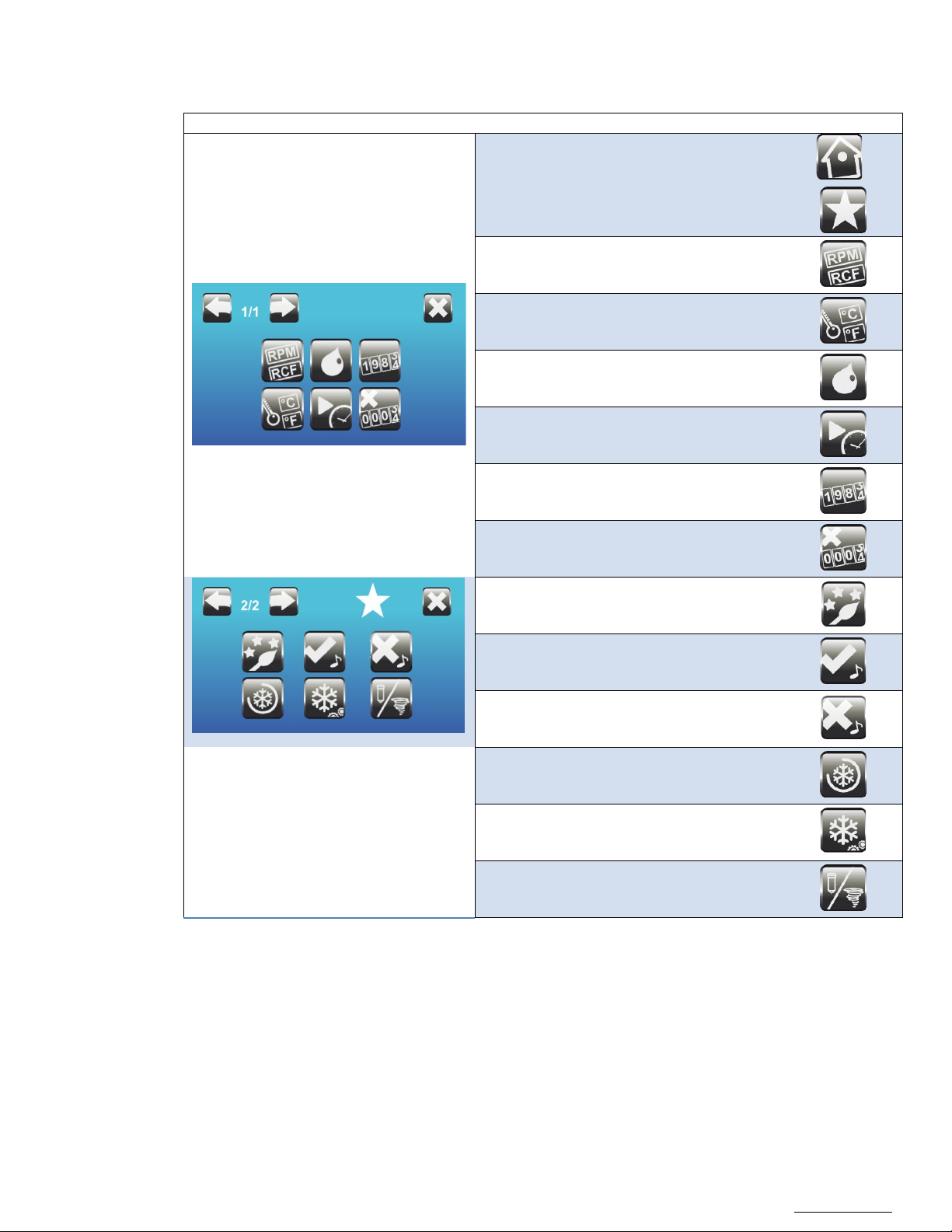
6.2.12 User Preference
Access the « User Preferences » menu via the
following icons:
• Type of speed displayed: RPM or RCF
(G force)
• Type of temperature displayed :
Celsius or Fahrenheit
• Frequency of Lubrication
• Timer settings
• Logbook
• Error logbook
• Background Color
• End of Cycle Alarm
• Error Message Alarm
;
• Post Cool
• Pre-Cool Function
• Temperature Display Mode
Page 26

OM0252 | Rev 4 May/2020
Page 26 of 59
NuAire, Inc. | 2100 Fernbrook Lane | Plymouth, MN 55447 | U.S.A | ph: 763.553.1270 | fx: 763.553.0459 | tf: 800.328.3352 | www.nuaire.com
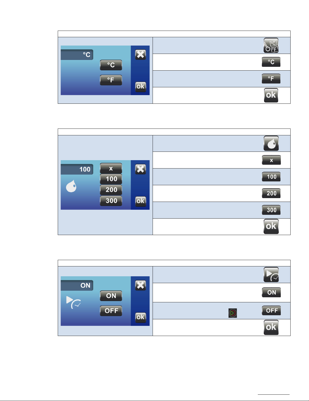
6.2.13 Type of Speed displayed (RPM OR RCF)
Visual
Instruction
Control
Select the unit you want displayed by
default:
• RPM: Rotation Per Minute
• RCF: Relative Centrifugal Force,
or G Force
Confirm
Do not turn the centrifuge off at this point
You now have to restart the unit.
Page 27
OM0252 | Rev 4 May/2020
Page 27 of 59
NuAire, Inc. | 2100 Fernbrook Lane | Plymouth, MN 55447 | U.S.A | ph: 763.553.1270 | fx: 763.553.0459 | tf: 800.328.3352 | www.nuaire.com
6.2.14 Type of Temperature displayed
Visual
Instruction
Control
Visual
Instruction
Control
Visual
Instruction
Control
• ON: The timer only starts when the
speed in the program
• OFF: The timer starts right when you
start the cycle (Press .)
Select you unit you want displayed by
default:
6.2.15 Frequency of lubrication
• °C: Degree Celsius
• °F: Degree Fahrenheit
Confirm
Select how many cycles you want between
each lubrication reminder.
• No reminder (Not recommended)
• 100 cycles (Default value)
• 200 cycles
• 300 cycles
6.2.16 Timer setting
Confirm
Select the type of timer:
centrifuge has reached the set
Confirm
Page 28
OM0252 | Rev 4 May/2020
Page 28 of 59
NuAire, Inc. | 2100 Fernbrook Lane | Plymouth, MN 55447 | U.S.A | ph: 763.553.1270 | fx: 763.553.0459 | tf: 800.328.3352 | www.nuaire.com
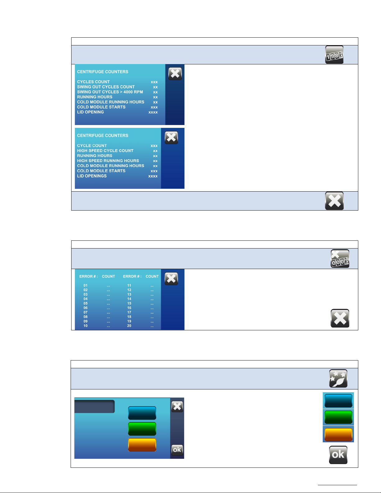
6.2.17 Access to logbook
Visual
Instruction
Control
The counters keep track of the life of the
Visual
Instruction
Control
The messages are recorded per error number,
Visual
Instruction
Color
centrifuge.
• CYCLE COUNT: Quantity of cycles on the centrifuge.
• SWING-OUT CYCLE COUNT: Quantity of cycles ran with a
swing-out rotor
• SWING-OUT CYCLE COUNT >4,000RPM: Quantity of cycles
ran with a swing-out rotor faster than 4,000RPM
• RUNNING HOURS: Amount of hours the centrifuge has
been used.
• COLD MODULE RUNNING HOURS : Amount of hours the
refrigeration has been running
• COLD MODULE STARTS : Number of time the refrigeration
has started (compressor)
• LID OPENINGS: Number of lid openings
Return
6.2.18 Access to error logbook
The error logbook makes it easier to service and
do maintenance on the unit.
making it easier to save all the errors and how
often they happen.
For more details on these error codes, refer to
section 6.2.22.
Return
6.2.19 Change background color
You can modify the background color of the
display
Choose the color you want.
Confirm
Page 29
OM0252 | Rev 4 May/2020
Page 29 of 59
NuAire, Inc. | 2100 Fernbrook Lane | Plymouth, MN 55447 | U.S.A | ph: 763.553.1270 | fx: 763.553.0459 | tf: 800.328.3352 | www.nuaire.com
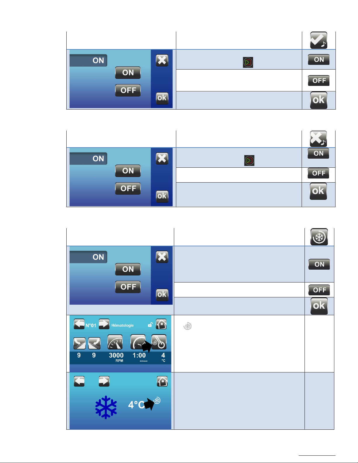
6.2.20 End of Cycle Alarm
This function activates a beep when the cycle is
• ON: Upon stop the signal is triggered
Pressing the key stops the signal.
• OFF: No signal at the end of the run.
This function activates a beep when an error
• ON : Upon error the signal is triggered
Pressing the key stops the signal.
• OFF: No signal upon error.
This is the default.
This function maintains the temperature in the
• ON: After closing the lid the refrigeration
Upon opening the lid the 4 hour timer will
restart.
• OFF: Bowl temperature is not maintained
between runs.
When Post Cool is activated this symbol
complete.
6.2.21 Error Message Alarm
6.2.22 Post Cool
This is the default.
message appears
bowl between runs.
the unit will maintain the temperature
for 4 hours.
Note:
appears:
- On the main screen next to the
thermometer.
- On the Precool screen right of the
temperature.
Page 30
OM0252 | Rev 4 May/2020
Page 30 of 59
NuAire, Inc. | 2100 Fernbrook Lane | Plymouth, MN 55447 | U.S.A | ph: 763.553.1270 | fx: 763.553.0459 | tf: 800.328.3352 | www.nuaire.com
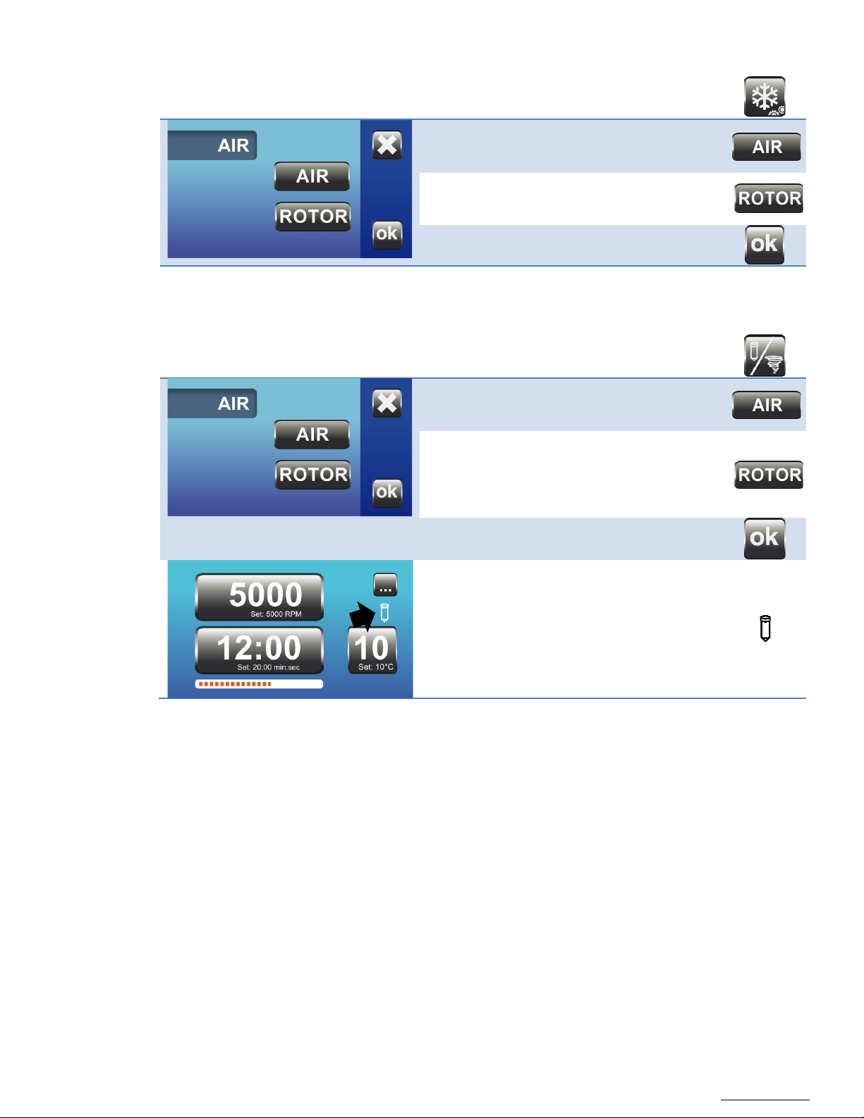
6.2.23 Pre Cool Function
• AIR: Cooling to the temperature in the
• ROTOR: Cooling for 22 minutes. At this
are cooled.
• AIR: The temperature displayed is the
This is the default
• ROTOR: The temperature displayed is
temperature.
During Centrifugation:
Allows Pre Cool to 4⁰C in air or rotor mode.
bowl. This is the default.
point the rotor and accessories
6.2.24 Temperature Display Mode
Allow for display of air or rotor temperature.
temperature of the air in the bowl.
that of a sample in a tube. The
sample must have been
previously stored at the same
If the Rotor mode is selected the tube
appears.
If the Air mode is selected no logo appears.
Pressing the temperature button can
temporarily change the display mode.
Page 31
OM0252 | Rev 4 May/2020
Page 31 of 59
NuAire, Inc. | 2100 Fernbrook Lane | Plymouth, MN 55447 | U.S.A | ph: 763.553.1270 | fx: 763.553.0459 | tf: 800.328.3352 | www.nuaire.com
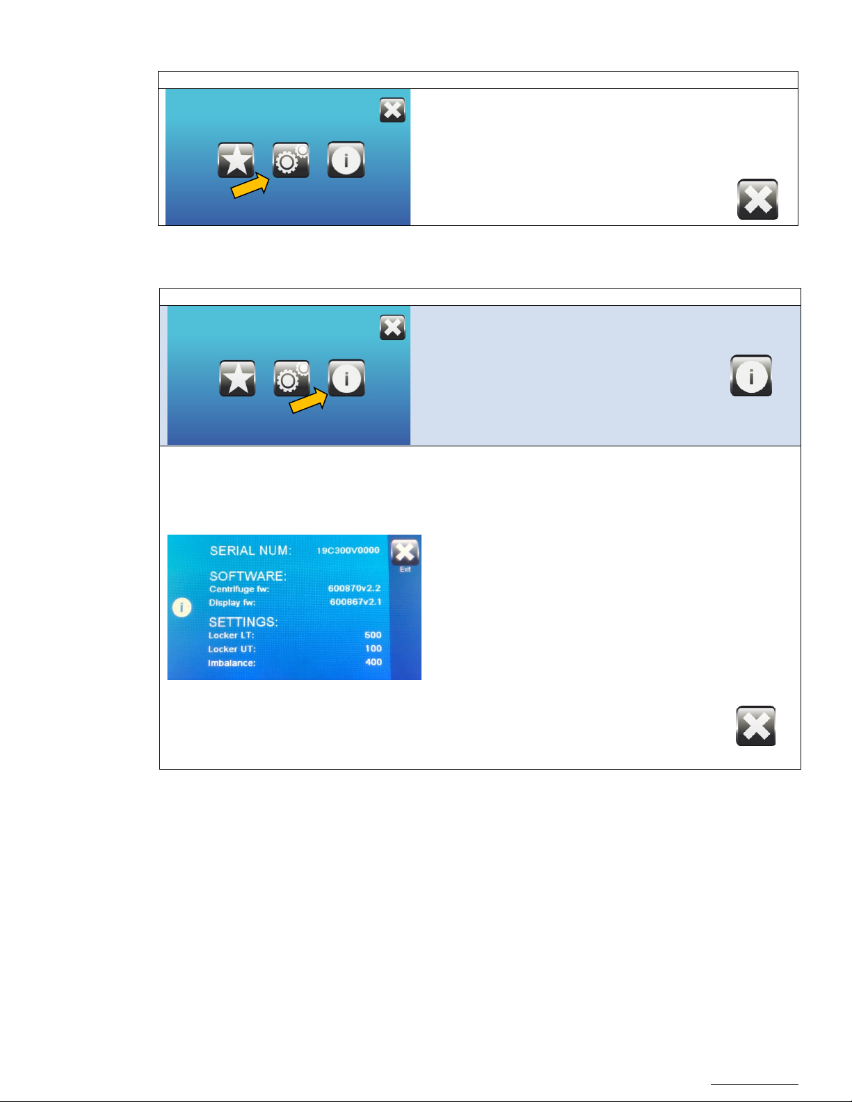
6.2.25 Service Menu
Visual
Instruction
Control
This menu provides general information on
Visual
Instruction
Control
6.2.26 Information
This menu is only accessible to certified service
companies.
Exit
Access the menu through this icon :
the Software and Hardware of the
centrifuge :
SERIAL NUMBER: Unique identification
number of the centrifuge
Centrifuge fw: Software version of the
microcontroller
Display fw: Software version of the display
µController Board Id: ID of the
microcontroller electronic board
Locker LT: Locking tempo of the lid
Locker UT: Unlocking tempo of the lid
Imbalance: Imbalance calibration setting
Return
Page 32

OM0252 | Rev 4 May/2020
Page 32 of 59
NuAire, Inc. | 2100 Fernbrook Lane | Plymouth, MN 55447 | U.S.A | ph: 763.553.1270 | fx: 763.553.0459 | tf: 800.328.3352 | www.nuaire.com
7.0 Care and Maintenance
CAUTION
!
CAUTION
!
All maintenance actions on this equipment must be performed by a qualified
technician who is familiar with the proper maintenance procedures required
for this equipment
The device and its accessories may be contaminated.
Apply decontamination measures required before any maintenance.
Turn off the centrifuge power switch. Ensure you lock the switch when working on the
unit, to avoid any accident from a third party.
Special care must be provided to maintain the original terms of safety and performance,
to extend the life of accessories. A visual inspection can identify any signs of wear. An
annual inspection may be requested according to relevant regulations
7.1 Care and Cleaning
7.1.1 Authorized maintenance products
Users should not use cleaning or decontamination methods different from those recommended by the
manufacturer, as they may cause damage to the unit.
The following products and materials are allowed for maintenance:
- Distilled water,
- 70% IPA, peroxides or quaternary ammonium surface disinfectants.
- Lint-free cloth
- Soft non-metallic brush
- Lanolin or silicone spray
Forbidden products and materials:
- Chlorine-containing products (Bleach, chlorides, ...)
- Saltwater
- Wire brush
7.1.2 Centrifuge
Perform regular cleaning of the following parts to prevent any risk of corrosion in case of persistent impurity, and to
ensure the hygiene of the working equipment.
External parts lid & keyboard:
- Use fluids and tissues impregnated with hydro-alcoholic solution or quaternary ammonium
- Check that the air vents are not obstructed.
Centrifuge chamber:
- Remove the rotor before cleaning the tank.
- Dry thoroughly after cleaning.
- Do not use fluffy fabric.
- Replace the rotor after cleaning the tank.
Page 33
OM0252 | Rev 4 May/2020
Page 33 of 59
NuAire, Inc. | 2100 Fernbrook Lane | Plymouth, MN 55447 | U.S.A | ph: 763.553.1270 | fx: 763.553.0459 | tf: 800.328.3352 | www.nuaire.com
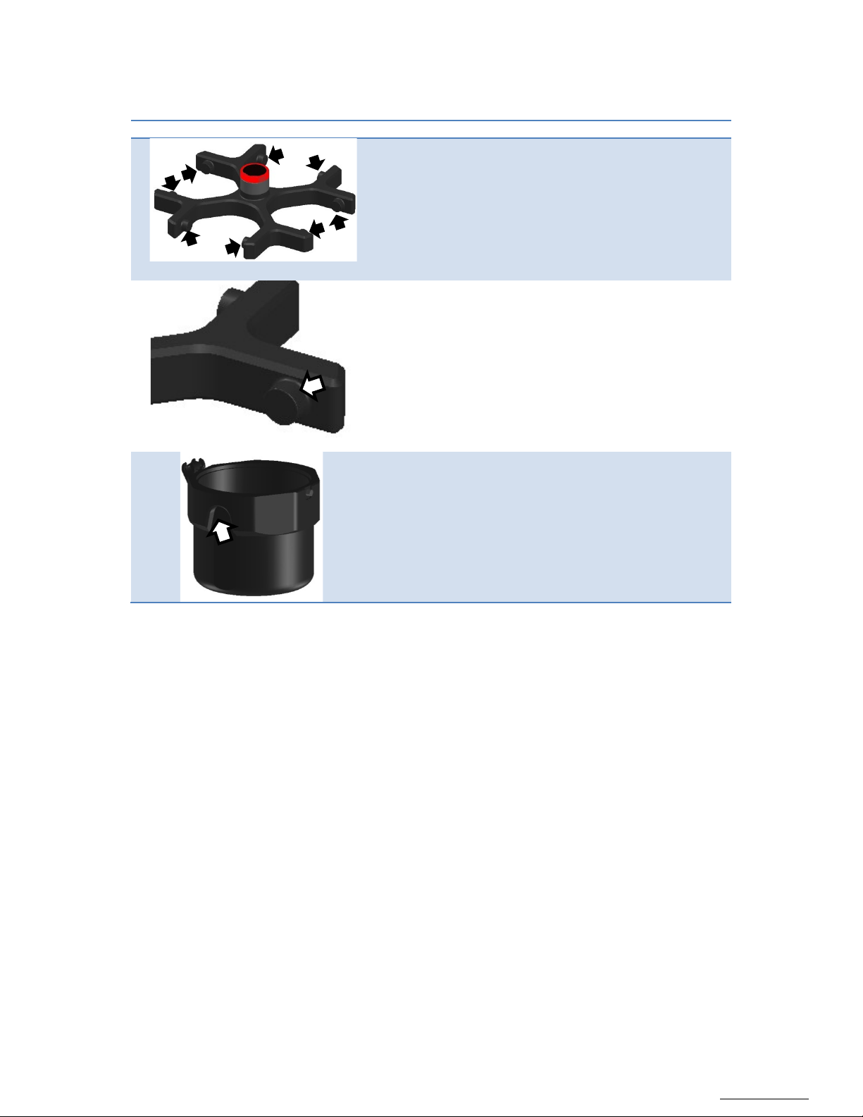
7.1.3 Rotor & Accessories
Image
Operation
Fig. 1 Rotor
To ensure a proper swinging movement of the buckets,
Fig. 2 Trunions
Remove the leftover grease and dust.
Also clean the buckets, more specifically the area in contact
Use clear or distilled water to clean the rotor and buckets. A soft non-metallic brush or lint-free cloth can be used.
Dry the rotor and accessories ensuring the least accessible areas are wiped.
clean all 8 trunions of the rotor.
Apply a thin layer of food quality grease (provided).
Make sure to set the “greasing reminder” in the User Preferences menu.
To prolong the life of accessories, you can then place a thin film of silicone spray or lanolin.
Rotors, buckets, inserts can be autoclaved at 122.5 ° C / 252 ° F / 215 kPa for 15 minutes
Note: When autoclaving, buckets, inserts, and rotors must be separated from each other.
Autoclaving causes accelerated aging of plastics, and may change the color of the plastic.
Perform regular cleaning to prevent any risk of corrosion in case of persistent impurity,
and to ensure the hygiene conditions of working equipment.
7.1.4 Disinfection / Decontamination
Bio hazardous, radioactive and/or toxic materials:
Before any intervention, to ensure the safety of the operator, please refer to the laboratory’s decontamination
protocol. The centrifuge and its accessories may be contaminated and require remediation in this case.
with the trunions.
Page 34
OM0252 | Rev 4 May/2020
Page 34 of 59
NuAire, Inc. | 2100 Fernbrook Lane | Plymouth, MN 55447 | U.S.A | ph: 763.553.1270 | fx: 763.553.0459 | tf: 800.328.3352 | www.nuaire.com
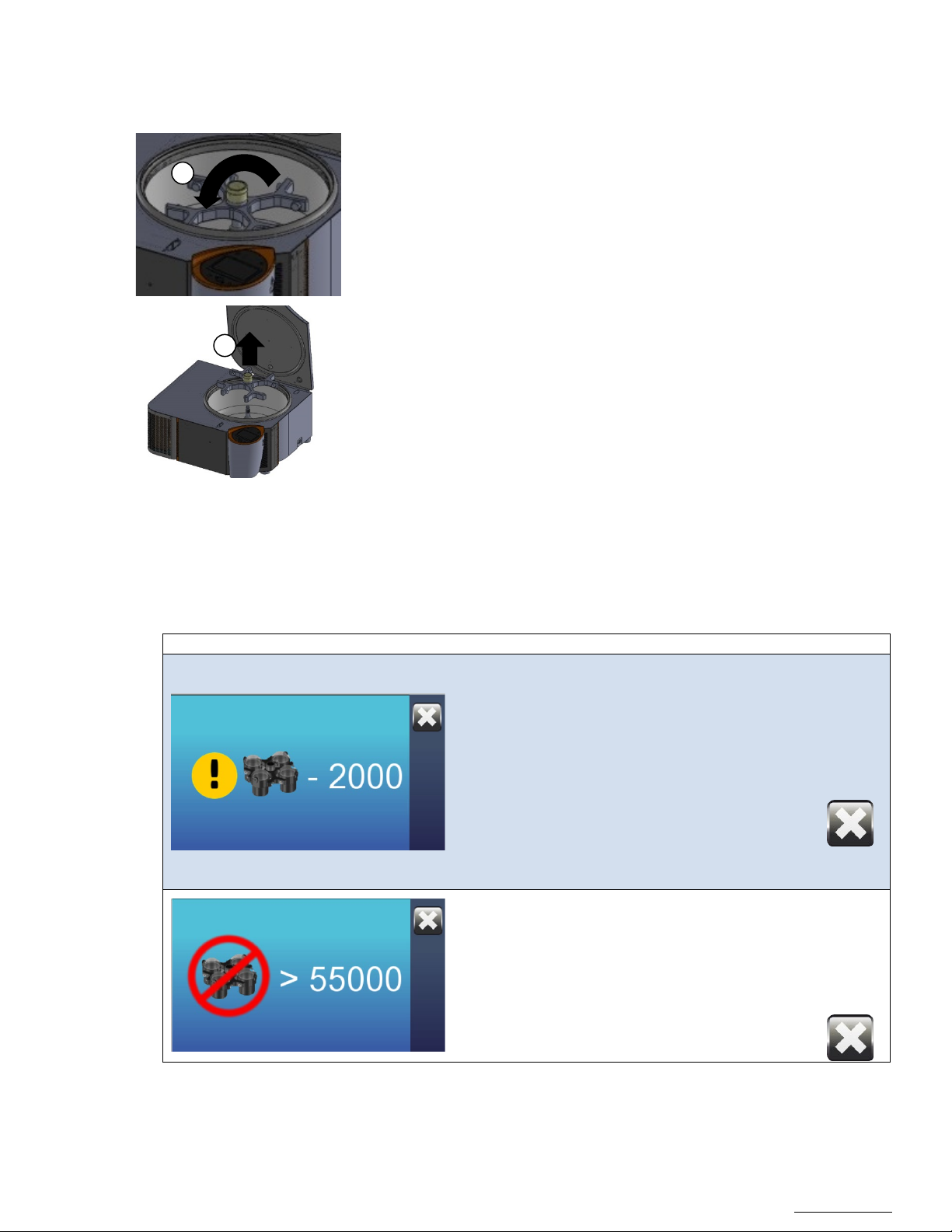
7.1.5 Dismantling the rotor
Visual
Instruction
Control
When there is only 2,000 cycles left before the end
3
2
1. Open the lid.
2. Grab the red wheel on top of the rotor and turn it
counterclockwise while holding the rotor firmly. Once you hear
a “click” sound, the rotor is unlocked
3. Grab and lift the rotor with both hands once it’s unlocked.
4. Set the rotor on a flat surface or on one of NuAire’s rotor stand.
7.1.6 Limiting the duration of operation
The use of accessories and the rotors is limited in time to ensure the integrity of their mechanical strength.
These limits are marked on the accessories.
of the theoretical life time of the rotor, this screen
will be displayed. It shows the amount of cycles left
before the rotor should stop being used (rotor and
buckets). This value will decrease by 1 each time the
rotor is being used.
You can still use the centrifuge, but only as long as
the value is higher than 0. Anticipate the purchase of
a new set of rotor + buckets in the near future.
Once the rotor has reached the end of its theoretical
life time, the screen will inform you that the rotor
cannot be used.
The rotor and buckets are obsolete and have to be
replaced promptly. A certified technician has to
configure the centrifuge for the new rotor.
Page 35

OM0252 | Rev 4 May/2020
Page 35 of 59
NuAire, Inc. | 2100 Fernbrook Lane | Plymouth, MN 55447 | U.S.A | ph: 763.553.1270 | fx: 763.553.0459 | tf: 800.328.3352 | www.nuaire.com
7.1.7 Checking and testing accessories
CAUTION
!
Check that no trace of corrosion appears. Check also the absence of any
mechanical damage (traces of impact, corrosion, cracking), or wear on the
rotor and bucket.
In order to ensure optimal performances, once the accessories have reached half of their theoretical life time, we
recommend inspecting them. This life time is different from one accessory to the other, and the value is engraved on
the accessory (i.e.: Max cycles: 55,000 means that the accessory has a theoretical life time of 55,000 cycles)
For safety reasons, the use of accessories that have reached the end of their life cycle is prohibited. These
components must be replaced.
7.1.8 Storage of accessories
Do not store the accessories on a wire rack. Oxidation build-up may appear and show premature wear of accessories
7.1.9 Annual maintenance
A periodic check of the centrifuge and accessories is required. Checks must also be carried out in accordance with the
regulations in force: Functional (lubrication of the drive shaft, the lock, readability of labels), security (continuity of
the protective ground connection, checking & maintenance of rotors and accessories) and centrifuge performance
checks are recommended at least once a year.
Replacement of consumables (grease, provided)
Check that the grounding of the device is always properly secured by its power cable and the wall outlet it is
connected to. The operator is not authorized to access the internal part of the equipment. A NuAire authorized
technician will ensure maintenance.
Page 36
OM0252 | Rev 4 May/2020
Page 36 of 59
NuAire, Inc. | 2100 Fernbrook Lane | Plymouth, MN 55447 | U.S.A | ph: 763.553.1270 | fx: 763.553.0459 | tf: 800.328.3352 | www.nuaire.com
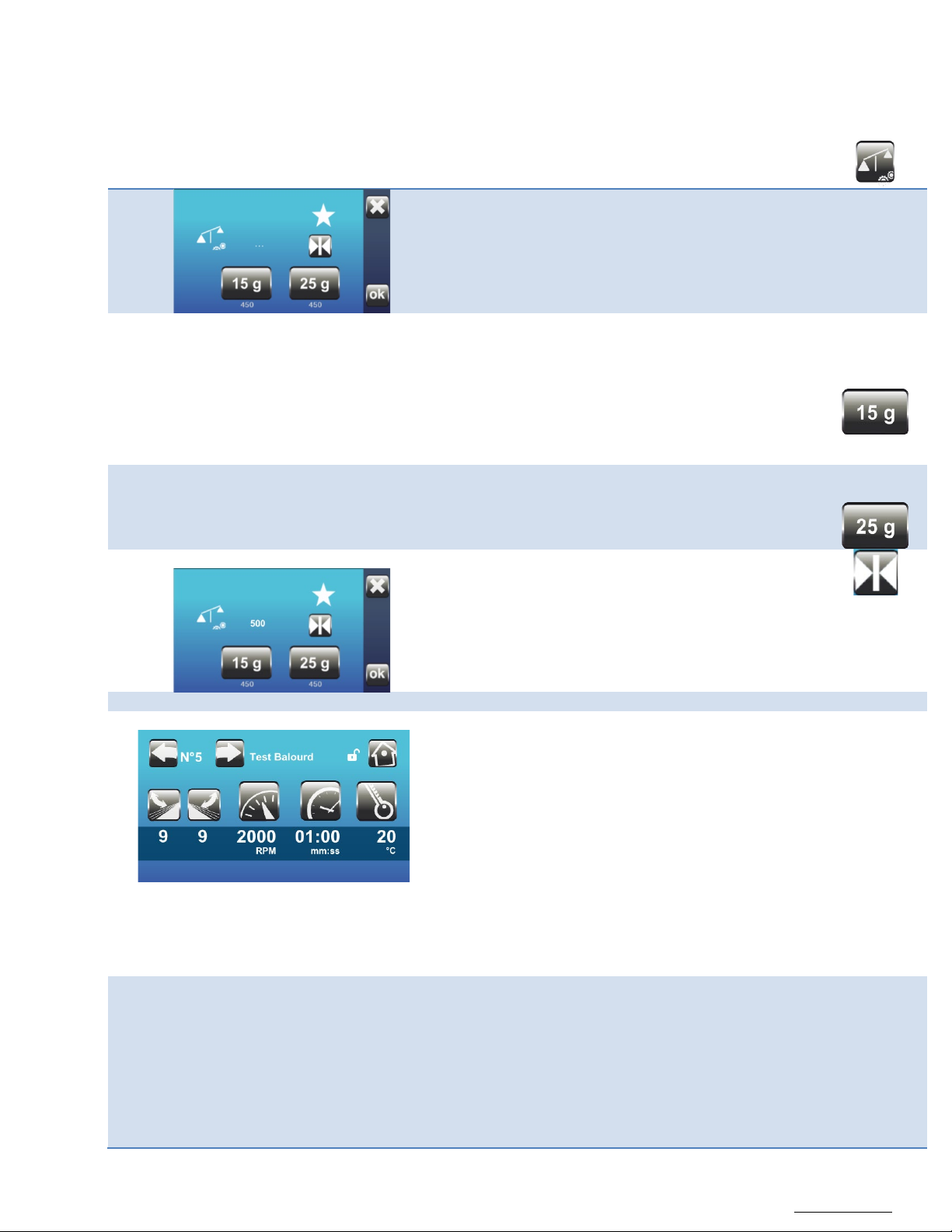
7.2 Unbalancing sensitivity detection
Low threshold
1. Place the round 15 gram weight in one of the
6. Open the lid and remove the 15 gram weight.
High threshold
7. Place the 25 gram weight in the same nacelle.
Average
11. Press on the Next button to average the setting.
Check
The following steps are compulsory.
High threshold:
maximum threshold of 25gr.
12. Place the 15 gr + 10 gr weights in a nacelle.
Low threshold:
15. Leave only a weight of 15 gr in a nacelle.
should take place normally.
The centrifuge has a reaction to the load balancing faults which may be different depending on the media on which the
centrifuge is placed. A calibration of the imbalance sensitivity is therefore necessary during installation.
Required equipment: Use the reference balancing kit AFI-71122002.
Access the unbalance sensitivity calibration menu.
Equip a rotor swing-out and its 4 nacelles in the
centrifuge.
Remove the inserts of the nacelles.
Do not adjust this threshold with a weight
greater than 25 gr.
This would cause a breach of warranty.
The appliance has been dimensioned for a
nacelles and close the lid,
2. Press the button “15gr”
3. The rotor accelerates until it stabilizes.
4. The centrifuge shakes, then the rotor slows down.
5. The low threshold is then determined. It appears
under the button “15 gr”. (e.g. 480)
8. Proceed in the same way as for the 15 gram weight.
9. The low threshold is then determined. (e.g. “520”)
10. Open the lid and remove the 25 gram weight.
(e.g. [480+520]/2 = 500 )
The average value is displayed.
By default, the factory setting value is 500.
13. Start the cycle. 2000 rpm / 1 minute / 9
Acceleration / Braking 9
14. The centrifuge must stop during the acceleration,
and display the message ERROR1:
The 25 gr imbalance is not tolerated.
Repeat the High threshold check 3 times: ERROR1
must appear each time.
16. Start the cycle. 2000 rpm / 1 minute /
9 Acceleration / Braking 9
17. The centrifuge should achieve the desired speed
8.0 Error Messages, Troubleshooting, Option-Diagnostics
and then slow down and stop without the following
error message appearing:
The 15 gr imbalance must be tolerated.
Repeat the Low threshold check 3 times: Each cycle
Page 37
OM0252 | Rev 4 May/2020
Page 37 of 59
NuAire, Inc. | 2100 Fernbrook Lane | Plymouth, MN 55447 | U.S.A | ph: 763.553.1270 | fx: 763.553.0459 | tf: 800.328.3352 | www.nuaire.com
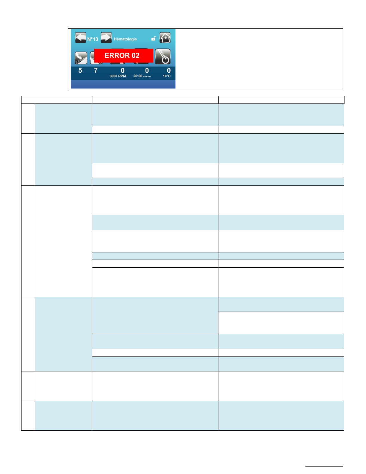
Error / Message
Cause
Solution
Close the lid.
starting a new cycle.
The lid sensor is malfunctioning.
Contact a Certified Technician.
Wait until complete stop.
Start a new cycle.
Install the centrifuge on a flat bench/table, as
described in manual.
The imbalance detector is not well calibrated.
Contact a Certified Technician.
Wait until complete stop.
manual.
The temperature set in the program is not
adapted.
The settings for speed / temperature are not
compatible with a normal utilization.
Make sure the samples can be cooled to down
hour
The refrigeration doesn’t work.
Contact a Certified Technician.
The temperature probe is malfunctioning.
Contact a Certified Technician.
Check the value of the temperature alarm
temperature.
A « no-brakes » stop is occurring.
Wait 30 minutes before opening the lid.
Turn the AC or Ventilation system on to obtain
manual.
The centrifuge is being used too intensively
(ventilated model).
The motor has been damaged
Contact a Certified Technician.
The temperature sensor on the motor has a bad
connection.
ERROR
MECHANISM
The micro contact doesn’t work.
not good.
The micro contact was seen as closed when it
Contact a Certified Technician.
In case of a problem, the display shows an error message and
an error number.
01 LOCK FAIL
02 IMBALANCE
BOWL
03
OVERTEMPERATURE
The lid is open when the centrifuge starts.
The rotor buckets are not loaded symmetrically.
The centrifuge is installed on an uneven bench.
The temperature in the bowl is higher than 43C;
the room temperature is too high.
The temperature of the samples is too high.
The difference between the air temperature and
the over temperature alarm set point is greater
than the set value.
Wait for complete closing of the lid before
Open the lid.
Load the buckets as shown in manual.
Turn the AC or Ventilation system on to obtain
an ideal ambient temperature as described in
to a temperature between 4C and 37C during 1
threshold.
Change program settings: speed and/or
The motor temperature is too high.
an ideal ambient temperature as described in
MOTOR
04
OVERTEMPERATURE
Let the centrifuge cool down between cycles.
Contact a Certified Technician.
MICROCONTACTOR
05
ON LOCKING
MICROCONTACT
06
NOT SEEN - OPEN
One of the micro contacts is damaged or nonworking.
There is a bad connection to the micro contacts.
The auxiliary micro contact is not working.
The connection of the auxiliary micro contact is
Contact a Certified Technician.
should have been seen as open when the
centrifuge started.
Page 38

OM0252 | Rev 4 May/2020
Page 38 of 59
NuAire, Inc. | 2100 Fernbrook Lane | Plymouth, MN 55447 | U.S.A | ph: 763.553.1270 | fx: 763.553.0459 | tf: 800.328.3352 | www.nuaire.com
MICROCONTACT
The power contactor doesn’t work.
properly.
Error / Message
Cause
Solution
The board with tachometer / accelerometer is
released after the centrifugation started.
The speed sensor is working improperly.
The connection to these parts is not good.
The speed signal was lost during rotation.
opened and run normally again.
The speed sensor is not working properly.
lost.
The speed measured is higher than the
Contact a Certified Technician.
The board with tachometer / accelerometer is
The microcontroller board is working improperly.
Bus I²C
Temperature probe
Problem of communication with the
temperature measurement.
The lid was manually opened or the hook was
Contact a Certified Technician.
Verify the power plug is connected properly.
Turn the switch on.
Verify that the temperature probe is properly
PT500)
ERROR OVERSPEED
SAFETY
The startup test of the overspeed safety has
failed.
Microcontrol board is defaulting: Replace the
control center.
07
NOT SEEN – CLOSED
The open position switch was released after the
lid closed.
The micro contact doesn’t receive a command.
The coil of the micro contactor is not working
The micro contact was seen as open when it
should have been seen as closed.
Contact a Certified Technician.
working improperly.
08 ERROR LID SAFETY
The connection to these parts is not good.
The sensor for the closed lid position was
NO SPEED SIGNAL
09
AT START
The board with tachometer / accelerometer is
working improperly.
The speed sensor is working improperly.
10 SPEED SIGNAL LOST
The board with tachometer / accelerometer is
working improperly.
The connection to these parts is not good.
The board with tachometer / accelerometer is
WRONG SPEED
11
SIGNAL
working improperly.
The connection to these parts is not good.
Magnets from the tachometer might have been
12 OVERSPEED Major error, the centrifuge will stop.
Bus I²C
13
Accelerometer
working improperly.
The connection to these parts is not good.
The lid slightly opened during the security auto
test when the cycle started.
The speed cannot be read within the first 5s of
the cycle.
Unit will be locked for 30 minutes. Acknowledge
error and after 30 minutes lid will be able to be
The speed signal is not correct.
maximum speed allowed for this rotor.
Problem of communication with the
accelerometer.
14
LID OPEN DURING
15
ROTATION
NO DISPLAY No power.
The microcontroller board is working improperly.
Manual lid opening during centrifugation.
Wrong calibration of locking mechanism.
released during the centrifugation.
Check the power in the laboratory.
installed under the lid and replace it if
TEMPERATURE
16
CONTROL ISSUE
Temperature probe out of service.
necessary.
Remove the probe and measure the resistance.
The value must be 500+ - 100 Ohm (Probe
17
Page 39

OM0252 | Rev 4 May/2020
Page 39 of 59
NuAire, Inc. | 2100 Fernbrook Lane | Plymouth, MN 55447 | U.S.A | ph: 763.553.1270 | fx: 763.553.0459 | tf: 800.328.3352 | www.nuaire.com
Error / Message
Cause
Solution
2 possible situations:
opened as soon as error is acknowledged
2 possible situations:
opened as soon as error is acknowledged
Signal permanently lost:
Impossible to clear the Error and open the lid: 30
SPEED SIGNAL IS
18
LOST
SPEED SENSOR
19
ISSUE
minute safety timer is running,
Wait for 30mn before being allowed to open the
lid
Speed signal recovered during braking:
Error can be erased after full stop: lid can be
Signal permanently lost:
Impossible to clear the Error and open the lid: 30
minute safety timer is running,
Wait for 30mn before being allowed to open the
lid
Speed signal recovered during braking:
Error can be erased after full stop: lid can be
After erasing the error, cycle the power supply
and try to launch a new cycle. If Error 18 is
detected again, call technical service
After erasing the error, cycle the power supply
and try to launch a new cycle.
If Error 19 is detected again, call service
In case of malfunction, contact after-sales service if the previous table does not eliminate the error.
You will be asked for the type of centrifuge and the serial number for more effective troubleshooting.
Never try to disassemble or fix the unit on your own: the risks of getting injured or electrocuted are high. The manufacturer
warranty would then be void. Only a certified technician is authorized to perform such operations.
Page 40

OM0252 | Rev 4 May/2020
Page 40 of 59
NuAire, Inc. | 2100 Fernbrook Lane | Plymouth, MN 55447 | U.S.A | ph: 763.553.1270 | fx: 763.553.0459 | tf: 800.328.3352 | www.nuaire.com
9.0 Electrical/Environmental Requirements
NU- C300V
120V
60Hz
9 Amp
1 Phase
UL/UL-C Listed
NU- C300R
120V
60Hz
17 Amp
1 Phase
UL/UL-C Listed
NU- C300RF
120V
60Hz
17 Amp
1 Phase
UL/UL-C Listed
NU- C300V-E
230V
50Hz
4 Amp
1 Phase
CE Certified
NU- C300R-E
230V
50Hz
9 Amp
1 Phase
CE Certified
NU- C300RF-E
230V
50Hz
9 Amp
1 Phase
CE Certified
WARNING
!
9.1 Electrical (Supply Voltage Fluctuations Not to Exceed +/- 10%)
9.2 Operational Performance (for indoor use only)
Environment Temperature Range: 60⁰F - 85⁰F (15⁰C - 30⁰C)
Environment Humidity: Maximum relative humidity 80% for temperatures up to 31⁰C decreasing linearly to
50% relative humidity at 40⁰C
Environment Altitude: 6562 Feet (2000 meters) above sea level
9.3 Light Exposure
Standard Fluorescent Lighting @ 150 ft. candles (1614 LUX) maximum intensity.
9.4 Installation Category: 2.0
Installation category (overvoltage category) defines the level of transient overvoltage, which the instrument is designed to
withstand safely. It depends on the nature of the electricity supply and its overvoltage protection means. For example, in
CAT II, which is the category used for instruments in installations supplied from a supply comparable to public mains such as
hospital and research laboratories and most industrial laboratories, the expected transient overvoltage is 2500 V for a 230 V
supply and 1500 V for a 120 V supply.
9.5 Pollution Degree: 2.0 Pollution degree describes the amount of conductive pollution present in the operating environment. Pollution degree 2 assumes that normally only non-conductive pollution such as dust occurs with the exception of occasional conductivity caused by condensation.
9.6 Chemical Exposure
Chemical exposure should be limited to antibacterial materials used for cleaning and disinfecting.
CHLORINATED AND HALOGEN MATERIALS ARE NOT RECOMMENDED FOR USE ON STAINLESS STEEL SURFACES.
9.7 EMC Performance (classified for light industrial)
Emissions: EN61326
Immunity: EN61326
Class A equipment is intended for use in an industrial environment. In the
documentation for the user, a statement shall be included drawing attention to the fact
that there may be potential difficulties in ensuring electromagnetic compatibility in
other environments, due to conducted as well as radiated disturbances.
Page 41
OM0252 | Rev 4 May/2020
Page 41 of 59
NuAire, Inc. | 2100 Fernbrook Lane | Plymouth, MN 55447 | U.S.A | ph: 763.553.1270 | fx: 763.553.0459 | tf: 800.328.3352 | www.nuaire.com
Page 42
OM0252 | Rev 4 May/2020
Page 42 of 59
NuAire, Inc. | 2100 Fernbrook Lane | Plymouth, MN 55447 | U.S.A | ph: 763.553.1270 | fx: 763.553.0459 | tf: 800.328.3352 | www.nuaire.com
10.0 Disposal and Recycle
Component
Material
Main Cabinet
Painted Steel
Bowl
Stainless Steel
Inner Lid
Plastic
Motor
Various Steel/Copper
Printed Wiring Assembly
Lead Free Electronic
Wire
PVC Coated Copper
Connectors
Nylon
Hardware
Stainless Steel and Steel
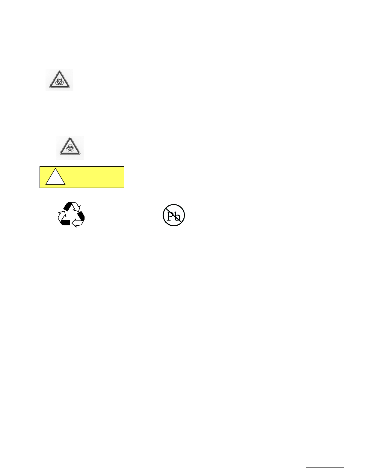
BIOHAZARD
RECYCLE
LEAD FREE
CAUTION
!
Before disposing the equipment, it must be decontaminated and cleaned to protect people, the environment and equipment.
Legal regulations must be observed when disposing of the unit.
Electrical appliances are governed by national regulations based on the 2002/96/EC European Directive
on electrical and electronic equipment waste WEEE.
According to this directive, no equipment supplied after August 13, 2005 in the Business-to-Business
sector - which includes this centrifuge - must be disposed of with household waste.
For easy identification, the appliances are marked with the symbol displaying a crossed out dustbin.
Centrifuges that are no longer in use and are ready for disposal contain reusable materials.
ALL components may be disposed and/or recycled after they are known to be properly disinfected.
Prior to any disassembly for disposal, the centrifuge must be decontaminated.
Note: Material type can be verified with use of a magnet with stainless and aluminum being non-magnetic.
Page 43
OM0252 | Rev 4 May/2020
Page 43 of 59
NuAire, Inc. | 2100 Fernbrook Lane | Plymouth, MN 55447 | U.S.A | ph: 763.553.1270 | fx: 763.553.0459 | tf: 800.328.3352 | www.nuaire.com
Annexes
1
.
60
2
1
−
= sradrpm
π
g
rN
RCF
5
2
2
10.
9
π
=
2
1000
118.
1
×
×=
N
r
F
r
F
N
×
×=
118.1
1000
RCF
Duration
1.0 Theoretical Basics of Centrifugation
1.1 Basics
Relative Centrifugal Force
In customary practices and usages of centrifugation, the quantization unit of angular velocity (denoted N), is the revolution
per minute (abbreviated rpm, RPM, r / min, or r • min-1). This is a measure of frequency of rotation. It corresponds to the
number of full rotations completed in one minute around a fixed axis.
The derived frequency unit for SI units is Hertz, with the symbol Hz. Its expression in terms of SI is s-1.
Laboratory centrifuges are used to separate solids of different densities in suspension, applying the relative centrifugal
force (RCF for short) on samples. The effective force increases with the square of the rotational speed and distance from
the axis of rotation. This force, known as "g-force" is quantified as the number of "g" applied to the sample. No SI units are
provided.
The following formula is used to convert the angular speed to "g-force"
RCF Relative Centrifugal Force, "g"
N: angular velocity, revolutions per minute
r: radius of the circular path of the sample, mm
g: acceleration of standard gravity, 9806 65 meters per second per second (ms-²)
The relative centrifugal force depends on the speed and the rotation radius.
An approximation, denoted F, is used in practice to calculate the value of the relative centrifugal force:
Speed, based on the relative centrifugal force is calculated by the following formula:
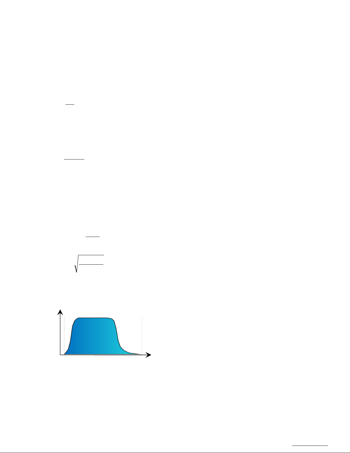
Integral spin
It is the accumulated relative centrifugal force acting on the centrifuged object at the corresponding time.
It is outlined by the colored surface of the chart below.
Page 44
OM0252 | Rev 4 May/2020
Page 44 of 59
NuAire, Inc. | 2100 Fernbrook Lane | Plymouth, MN 55447 | U.S.A | ph: 763.553.1270 | fx: 763.553.0459 | tf: 800.328.3352 | www.nuaire.com
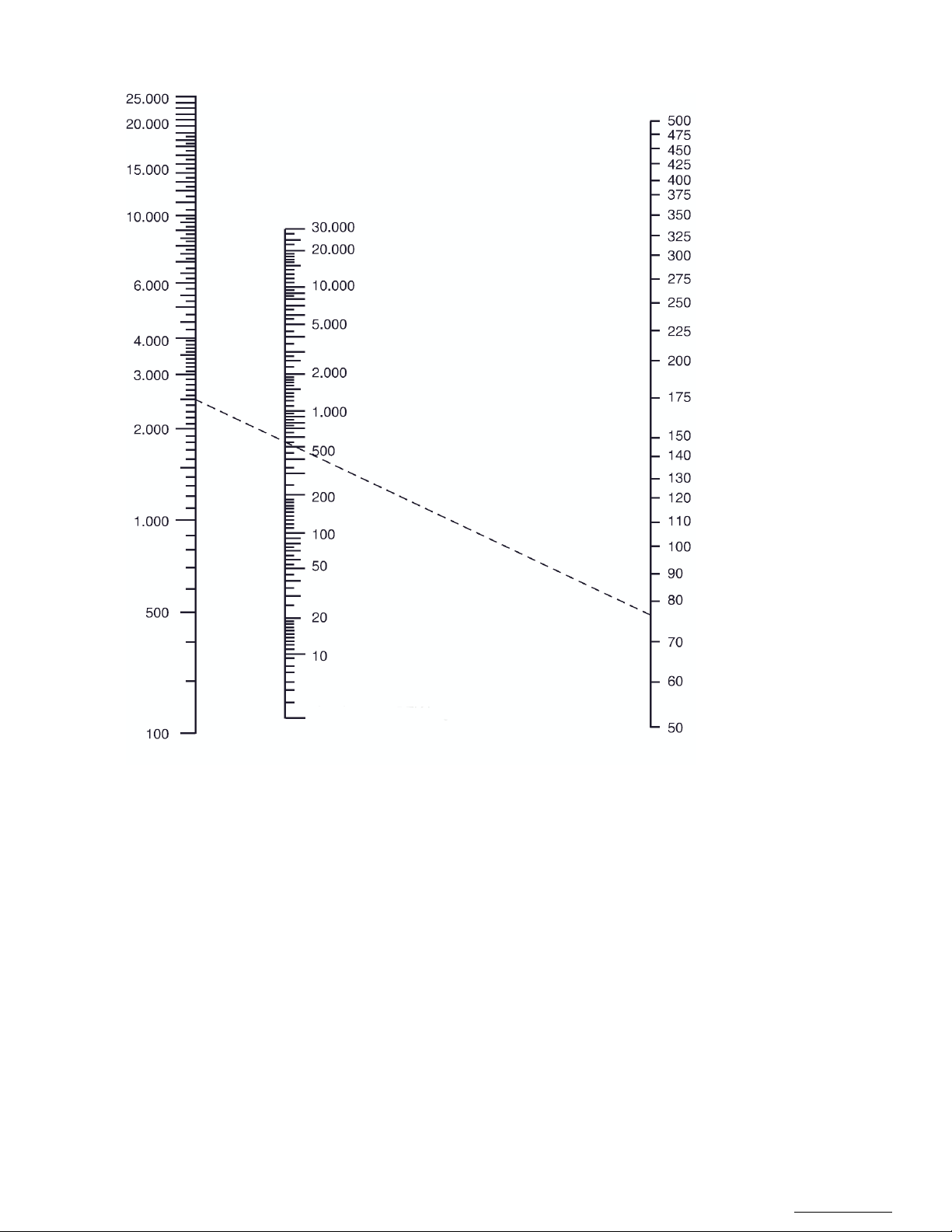
1.2 Nomogram
Radius (mm)
RCF (Number of grams)
RPM (r/min)
The nomogram graphically connects by a line segment a speed to the relative centrifugal force (RCF) as a function of the
radius of rotation selected.
In the example above, the speed of 2500 rpm corresponds to a relative centrifugal force of 550 g for a radius of rotation
of 79 mm
Page 45

OM0252 | Rev 4 May/2020
Page 45 of 59
NuAire, Inc. | 2100 Fernbrook Lane | Plymouth, MN 55447 | U.S.A | ph: 763.553.1270 | fx: 763.553.0459 | tf: 800.328.3352 | www.nuaire.com
1.3 Logbook
Date
Operator
RPM
RCF
Duration
T°
Rotor
Incidents
Example of table to monitor the use of the centrifuge and accessories.
Page 46
OM0252 | Rev 4 May/2020
Page 46 of 59
NuAire, Inc. | 2100 Fernbrook Lane | Plymouth, MN 55447 | U.S.A | ph: 763.553.1270 | fx: 763.553.0459 | tf: 800.328.3352 | www.nuaire.com
2.0 Accessory Specifications
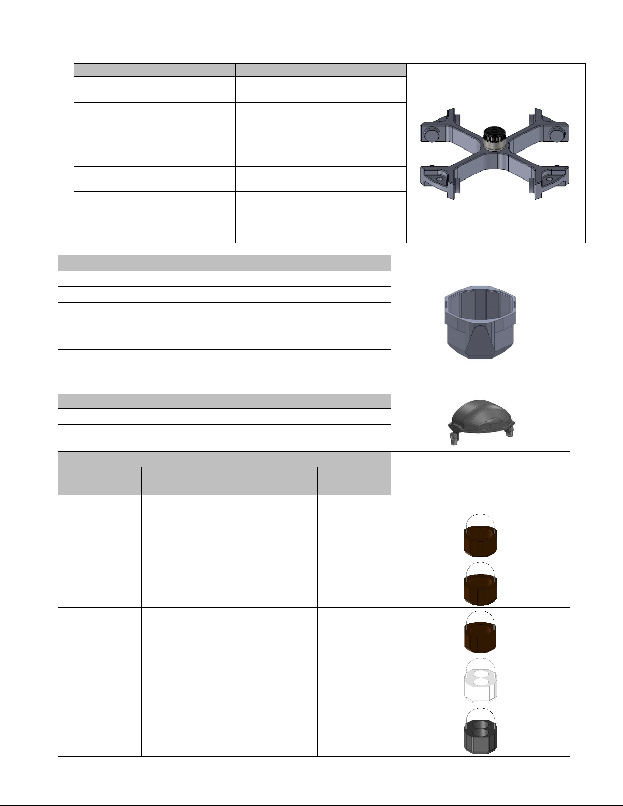
Rotor
Part number:
NU-RX1000
Description:
4 liters swing-out rotor
Maximum capacity:
4x1000 ml
Fastening:
ClickSpin system
Maximum rotor speed
3500 rpm
Maximum centrifugal force of the
rotor
2750 xg (with NU-B1000 buckets)
Lifetime
(Indicative duration)
50,000 cycles
8 years
Maximum
centrifugal force
NU-C300 Ventilated
3500 rpm
2750 xg
NU-C300 Refrigerating
3500 rpm
2750 xg
Buckets
Part number:
NU-B1000
Description :
1 000 ml bucket (Set of 4)
Maximum speed
3500 rpm
Maximum RCF
2750 xg
Maximum capacity
1750 grams
Lifetime
(Indicative duration)
50,000 cycles
8 years
Maximum Radius(***) :
201 mm
Lid
Part number:
NU-L1000
Description:
Sealed lid for 1000 ml bucket
(Set of 4)
Inserts (Set of 2 OR 4)
Total capacity
(Rotor)
NU-4T750F
196 mm
1x 750 ml Bottle
4
NU-4T625F
196 mm
1x 625 ml Bottle
4
NU-4T500C
196 mm
1x 500 ml Bottle
4
NU-290F
183 mm
2x 290 ml Bottle
8
NU-4T250C
198 mm
2x 250 ml Bottle
8
Centrifuge performance Maximum speed
Part number Radius(*) Capacity per insert
Flat bottom
Flat bottom
Flat bottom
Flat bottom
Conical bottom
(Without Lid Bucket)
Page 47
OM0252 | Rev 4 May/2020
Page 47 of 59
NuAire, Inc. | 2100 Fernbrook Lane | Plymouth, MN 55447 | U.S.A | ph: 763.553.1270 | fx: 763.553.0459 | tf: 800.328.3352 | www.nuaire.com
NU-4T200
198 mm
2x 225 ml Bottle
2x 175 ml Bottle
8
NU-4T50C
198 mm
10x 50 ml Bottle
40
NU-4T30S
185 mm
10x 30 ml Bottle
40
NU-4T15C
196 mm
24x 15 ml Bottle
96
NU-4T10
188 mm
39x 10 ml Blood
156
NU-4T5
188 mm
50x 5-7 ml Blood
Tube
200
NU-4T2
182 mm
50x Microtube
200
(*) The radius is the distance between the rotor shaft and the bottom of the insert holes when the bucket is spinning in a
horizontal position (during centrifugation)
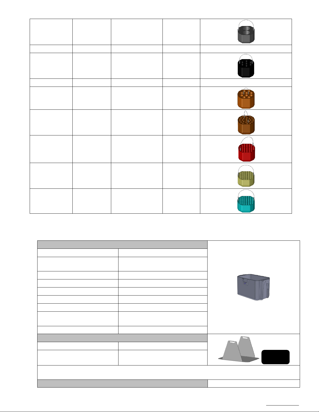
Microplate carrier
Part number :
NU-BXDW4
Description:
Microplate carrier for NU-RX1000 rotor
(Set of 2 OR 4)
Maximum speed
3500 rpm
Maximum RCF
2655 xg
Microplate capacity
6 x 96 wells
Deepwell block capacity
1 x 96 wells
Maximum capacity :
800 grams
Lifetime
(Indicative duration)
50,000 cycles
8 years
Maximum Radius :
194 mm
Included :
Part number :
NU-TXDW4
Description:
Stainless Steel Extractor & Neoprene
(***)The radius is the distance between the rotor shaft and the bottom of the microplate carrier when the carrier is
spinning in a horizontal position (during centrifugation)
Microplate carrier lid
Picture not available
Conical bottom
Conical bottom
Skirted Conical Tube
Conical bottom
Collection Tube
39x Tube 14 ml urine
Collection Tube
23x 14 ml Urine
1,5 - 2 ml
pad (1 per bucket)
Page 48
OM0252 | Rev 4 May/2020
Page 48 of 59
NuAire, Inc. | 2100 Fernbrook Lane | Plymouth, MN 55447 | U.S.A | ph: 763.553.1270 | fx: 763.553.0459 | tf: 800.328.3352 | www.nuaire.com
Part number :
NU-LXDW4
Description:
Lid for microplate carrier (Set of 2)
Extractor & Pad
Part number :
NU-TXDW4
Description:
Stainless Steel Extractor & Neoprene
Configurations:
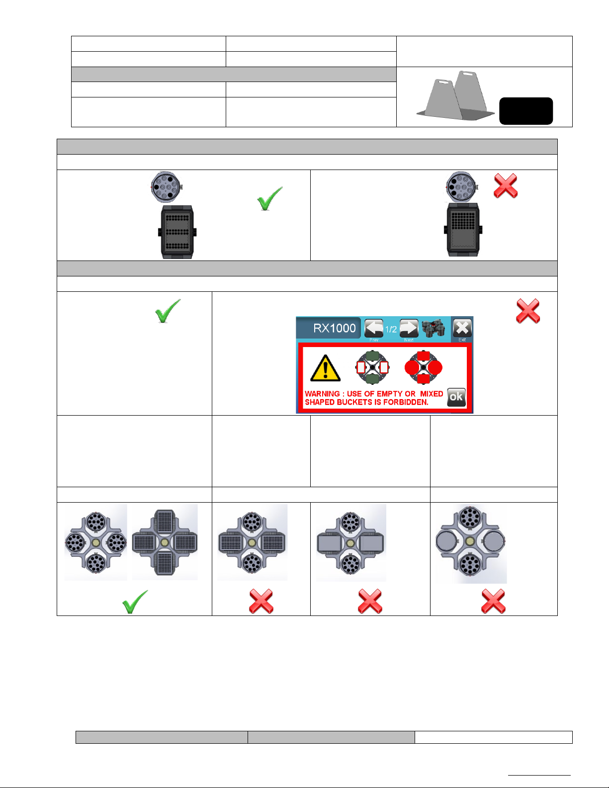
Loadings
Each bucket must be loaded evenly.
Loading the rotor
The rotor must be loaded evenly.
Allowed:
Forbidden:
2x NU-B1000 loaded buckets
2xNU-B1000
BXDW4 chargés
2 nacelles NU-B1000
insert)
2xNU-B1000 loaded buckets
Symmetrical loading
Asymmetrical loading
Incomplete loading
Rotor
pad (Set of 4)
Allowed:
(inserts & loaded tubes)
2 NU-B1000 buckets
With empty inserts.
Forbidden:
Note : A message appears when choosRX1000 rotor.
chargées
(portoirs & tubes
pleins)
2 nacelles NU-
loaded buckets
(inserts & loaded tubes)
2xNU-B1000 empty
buckets (ex: without
(inserts & loaded tubes)
2xNU-BXDW4 empty
buckets (ex: without insert)
Page 49
OM0252 | Rev 4 May/2020
Page 49 of 59
NuAire, Inc. | 2100 Fernbrook Lane | Plymouth, MN 55447 | U.S.A | ph: 763.553.1270 | fx: 763.553.0459 | tf: 800.328.3352 | www.nuaire.com
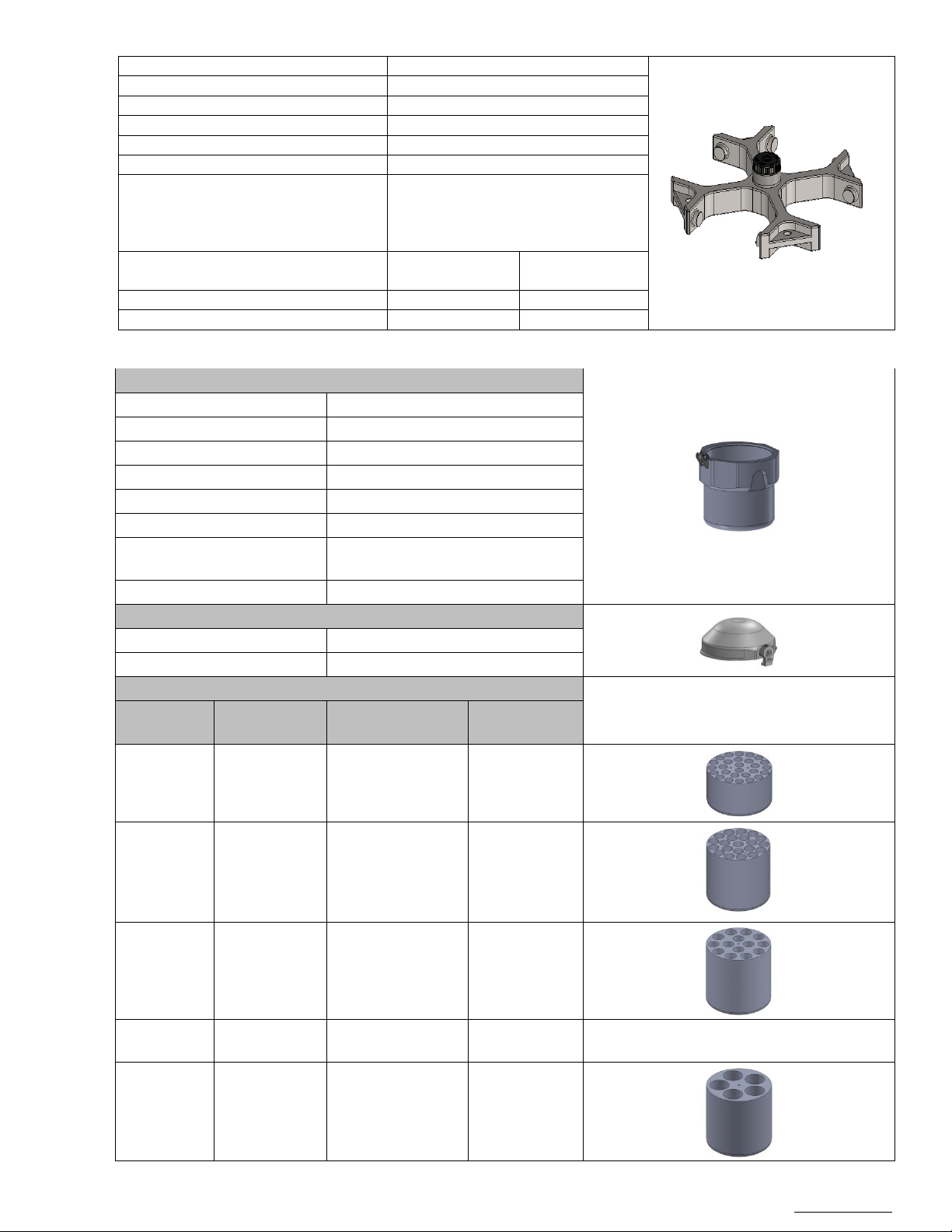
Part number:
NU-RX750
Description:
3 liter swing-out rotor
Maximum capacity:
4x750 ml
Fastening:
ClickSpin system
Maximum rotor speed
4600 rpm
Maximum centrifugal force of the rotor
4730 xg (with NU-B750 buckets)
Lifetime
100,000 cycles @ 3000 RPM
8 years
Maximum
centrifugal force
NU-C300 Ventilated
4500 rpm
4527 xg
NU-C300 Refrigerated
4600 rpm
4731 xg
Part number :
NU-B750
Description:
Round Bucket 750 ml (Set of 4)
Volume
750 ml
Maximum speed
4600 rpm
Maximum RCF
4730 xg
Maximum capacity :
1000 g
50 000 cycles
(8 years)
Maximum Radius :
200 mm
Lids
Part number :
NU-L750
Description :
Airtight lid 750 ml (Set of 4)
Inserts (Set of 2 OR 4)
Capacity per
insert
Capacity per
insert
Capacity per
insert
NU-3T5
198 mm
27x Tubes 5/7 ml
108
NU-3T10
198 mm
21x Tubes 10 ml (*)
(*)
84
NU-3T15C
200 mm
14x Tubes 15 ml
56
NU-3T50C
200 mm
6x Tubes 50 ml
Conical bottom
24
NU-3T50S
198 mm
5x Tubes 50 ml
20
Maximum
50,000 cycles @ more than 3000 RPM
Centrifuge performance Maximum speed
Accessories
Lifetime
Capacity per insert
(**)
(**)
Round bottom
Round bottom
8x Tubes 15 ml type
32
CPT Round bottom
Conical bottom
Skirted bottom
Page 50
OM0252 | Rev 4 May/2020
Page 50 of 59
NuAire, Inc. | 2100 Fernbrook Lane | Plymouth, MN 55447 | U.S.A | ph: 763.553.1270 | fx: 763.553.0459 | tf: 800.328.3352 | www.nuaire.com
(*) The radius is the distance between the rotor shaft and the bottom of the inserts when the bucket is spinning in a
horizontal position (during centrifugation)
(**) Same insert for many types of tubes.
(***) Can only be used without a lid
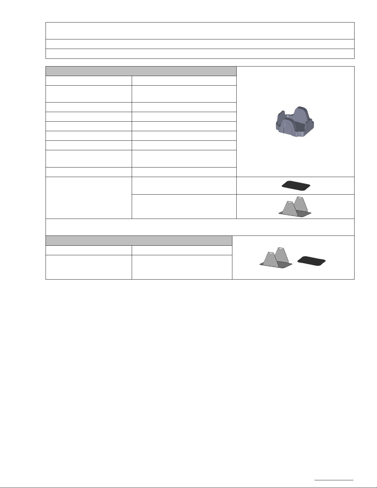
Support micro plaque
Part number:
NU-BXDW3
Microplate bucket for rotor NU-RX750
(Set of 2 OR 4)
Maximum speed
4600 rpm
Maximum RCF
4564 xg
Capacity standard Microplates
4 plates per bucket (total of 16)
Capacity Deep well blocks
1 block per bucket (total of 4)
Maximum capacity
800 grams
50,000 cycles
8 years
Maximum Radius(***) :
193 mm
(***) The radius is the distance between the rotor shaft and the bottom of the microplate bucket (without pad and
extractor) when the bucket is spinning in a horizontal position (during centrifugation)
Extractor & Pad
Reference:
NU-TXDW3
Description:
Stainless steel extractor and
(Set of 4)
Description :
Lifetime
Neoprene pad (1 per bucket)
Included :
Stainless Steel extractor (1 per bucket)
neoprene pad for rotor NU-RX750
Page 51
OM0252 | Rev 4 May/2020
Page 51 of 59
NuAire, Inc. | 2100 Fernbrook Lane | Plymouth, MN 55447 | U.S.A | ph: 763.553.1270 | fx: 763.553.0459 | tf: 800.328.3352 | www.nuaire.com
Possible Configurations:
Loading the buckets
Each bucket must be loaded evenly.
Loading the rotor
The rotor must be loaded evenly.
Allowed:
Forbidden:
Symmetrical loading
Incomplete loading
Asymmetrical loading
Allowed:
Forbidden:
Page 52
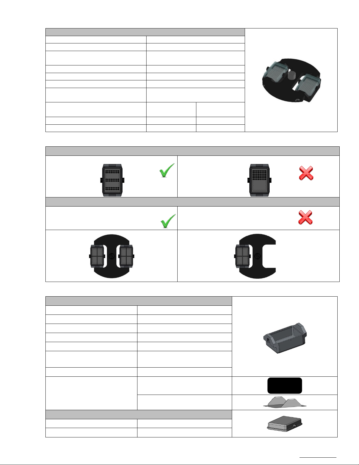
OM0252 | Rev 4 May/2020
Page 52 of 59
NuAire, Inc. | 2100 Fernbrook Lane | Plymouth, MN 55447 | U.S.A | ph: 763.553.1270 | fx: 763.553.0459 | tf: 800.328.3352 | www.nuaire.com
Swing-Out Rotor NU-RHDW
Rotor
Part number:
NU-RHDW
Description:
Microplate swing-out rotor
Maximum capacity:
2x 4 96-well microplates
2x 1 96-well "Deep Well" plate
Fastening:
ClickSpin system
Maximum rotor speed
5900 rpm (With NU-BHDW buckets)
Maximum centrifugal force of the rotor
6072 xg (With NU-BHDW0 buckets)
30,000 cycles at maximum speed
6 years
Maximum
centrifugal force
NU-C300 Ventilated
4500 rpm
3531 xg
NU-C300 Refrigerated
5100 rpm
4537 xg
Loading the buckets
Allowed:
Not allowed:
Loading the rotor:
Forbidden :
Asymmetrical loading
Buckets
Part number:
NU-BH
Description:
Micro titration buckets (Set of 2)
Capacity standard Microplates
4 plates per bucket (total of 8)
Capacity Deep well blocks
1 block per bucket (total of 2)
Maximum capacity :
720 grams
30,000 cycles at maximum speed
6 years
Maximum radius :
156 mm
Neoprene pad (Set of 2)
Stainless Steel Extractor (set of 2)
Lid Part number:
NU-LH
Description :
Airtight lid for Microplate (Set of 2)
Lifetime
Centrifuge performance Maximum speed
Possible Configurations:
(Buckets and lids not included)
Allowed:
Symmetrical loading
Accessories for NU-RHDW
Lifetime
Incomplete loading
Included :
Page 53

OM0252 | Rev 4 May/2020
Page 53 of 59
NuAire, Inc. | 2100 Fernbrook Lane | Plymouth, MN 55447 | U.S.A | ph: 763.553.1270 | fx: 763.553.0459 | tf: 800.328.3352 | www.nuaire.com
Angle Rotor NU-RA8-50
Rotor
Part number:
NU- RA8-50
Description:
8x 50 ml Angle rotor
Maximum capacity:
8x 50 ml Conical tubes
Maximum load
8 x 67 gr
Micro tube tilt:
25°
Fastening:
ClickSpin system
Maximum rotor speed
12100 rpm
Maximum centrifugal force of the rotor
16660 xg
Maximum
centrifugal force
NU-C300 Ventilated
10700 rpm
13000 xg
NU-C300 Refrigerated
12100 rpm
16660 xg
Maximum radius
102 mm
Rotor
Part number:
NU-RA16-5
Description:
16 x 5 ml Angle rotor
Maximum capacity:
16x 5 ml micro tubes
Maximum load
16 x 36 gr
Micro tube tilt:
45°
Fastening:
ClickSpin system
Maximum rotor speed
13200 rpm
Maximum centrifugal force of the rotor
21000 xg
Maximum
centrifugal force
NU-C300 Ventilated
13200 rpm
21035 xg
NU-C300 Refrigerated
13200 rpm
21000 xg
Maximum radius
107.8 mm
Loading the rotor
Allowed
Forbidden:
Lid Part number:
NU-LM2
Description:
Micro tube rotor airtight lid for rotors NU-RA30-2, NU-RA48-2 and
NU-RA16-5
Centrifuge performance Maximum speed
Angle Rotor NU-RA16-5
Centrifuge performance Maximum speed
Items included: Micro tube rotor airtight lid
(Lid included)
Possible Configurations:
An Even number of tubes spaced
evenly in the rotor.
Accessories for NU-RA16-5
Page 54
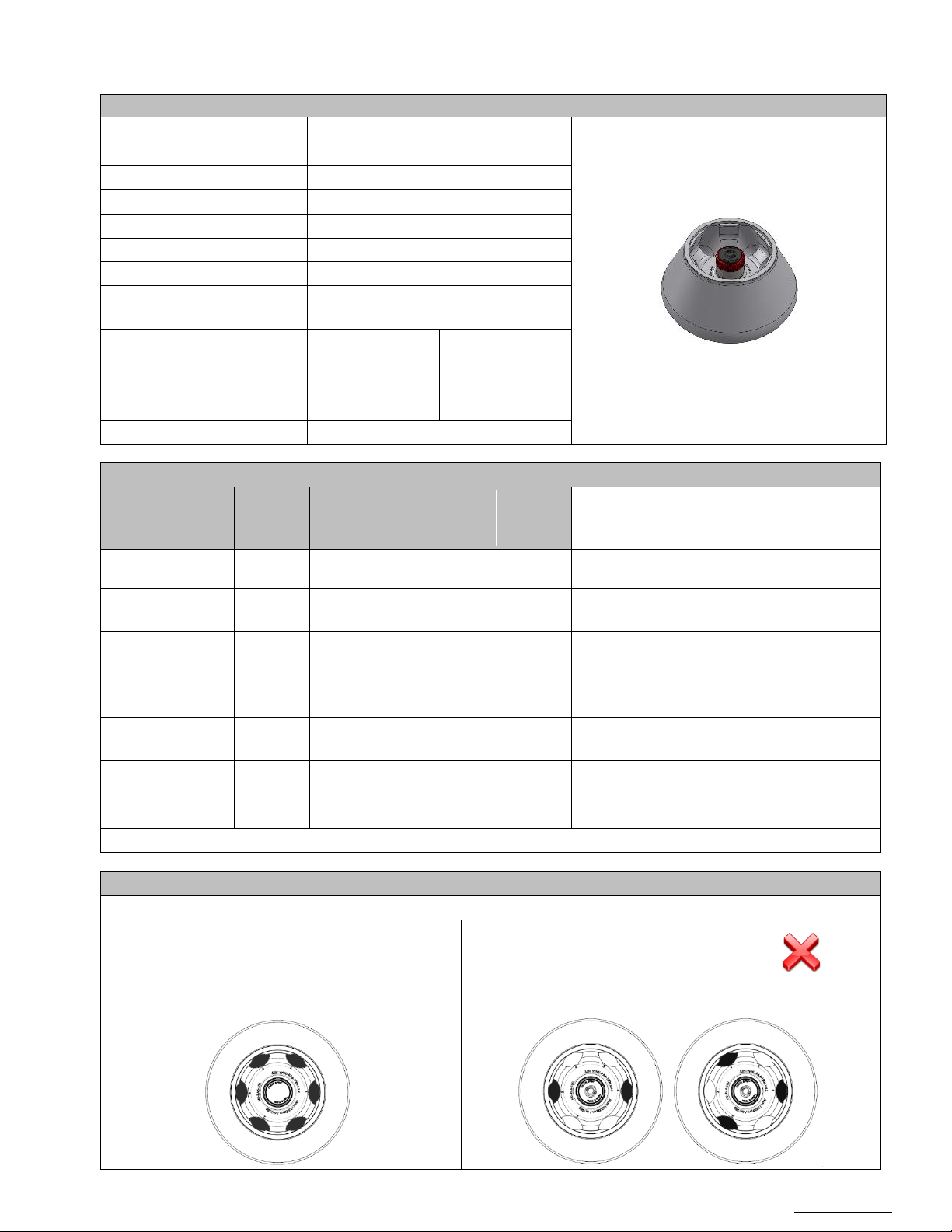
OM0252 | Rev 4 May/2020
Page 54 of 59
NuAire, Inc. | 2100 Fernbrook Lane | Plymouth, MN 55447 | U.S.A | ph: 763.553.1270 | fx: 763.553.0459 | tf: 800.328.3352 | www.nuaire.com
Angle Rotor NU-RA6-100
Rotor
Part number:
NU- RA6-100
Description:
Angular Rotor 6x 100 ml
Maximum capacity:
6x 100 ml Tube
Maximum load
6x 135 grams
Tube tilt:
28°
Fastening:
ClickSpin system
Maximum rotor speed
12100 rpm
Maximum centrifugal force of
the rotor
17351 xg
Maximum
centrifugal force
AFI-C300 Ventilated
10700 rpm
13568 xg
AFI-C300 Refrigerated
12100 rpm
17351 xg
Maximum radius
106 mm
Tubes adapters (Set of 6)
Total
(Rotor)
AFI-100R80-OAK
… mm
1x 80 ml Tube
AOR Advanced Oak Ridge
6
/
AFI-100R50C
… mm
1x 50 ml Tube
Conical bottom
6 / AFI-100R50-OAK
… mm
1x 50 ml Tube
AOR Advanced Oak Ridge
6 / AFI-100R30-OAK
… mm
1x 30 ml Tube
AOR Advanced Oak Ridge
6 / AFI-100R15C
… mm
1x 15 ml Tube
Conical bottom
6
/
AFI-100R510-OAK
… mm
1x 10 ml Tube
AOR Advanced Oak Ridge
6
AFI-100R10
… mm
1x 10 ml Tube 6 /
(*)The radius is the distance between the rotor shaft and the bottom of the tube cell.
Loadings
A rotor must be uniformly loaded.
Allowed:
Forbidden :
Centrifuge performance Maximum speed
Accessoriess
Part number
Radius
(*)
Capacity per insert
capacity
/
/
Configurations:
This rotor is not equipped with a lid.
To maintain performance, all cells without
exception must be equipped with a tube.
Page 55
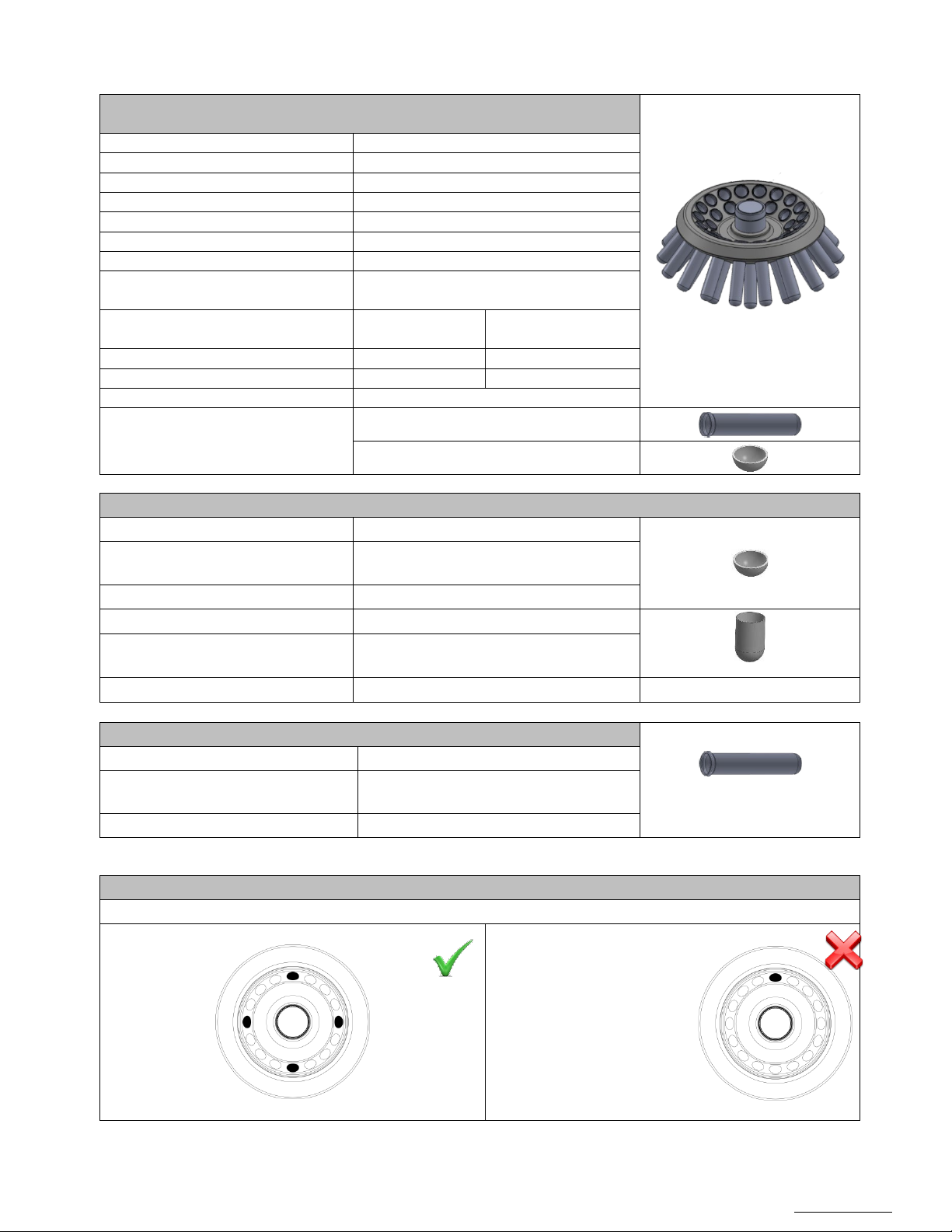
OM0252 | Rev 4 May/2020
Page 55 of 59
NuAire, Inc. | 2100 Fernbrook Lane | Plymouth, MN 55447 | U.S.A | ph: 763.553.1270 | fx: 763.553.0459 | tf: 800.328.3352 | www.nuaire.com
Angle Rotor NU-RA30-15
Rotor
Part number:
NU-RA30-15
Description:
30 x 15 ml Angle rotor
Maximum capacity:
30x 15 ml micro tubes
Maximum load
30 x 26 gr
Micro tube tilt:
53°
Fastening:
ClickSpin system
Maximum rotor speed
4800 rpm
Maximum centrifugal force of the
rotor
3606 xg
Maximum centrifugal
force
AFI-C200 Ventilated
4500 rpm
3169 xg
AFI-C200 Refrigerating
4800 rpm
3606 xg
Maximum radius
140 mm
Cups
Part Number:
NU-3015R
15 ml round-bottomed tube cups (Set of
30)
Maximum radius :
138 mm (with NU-3015S)
Part Number:
NU-3015C
Tubes for 15 ml tubes with conical bottom
(Set of 30)
Maximum radius :
137 mm (with NU-3015S)
Tubes
Part Number:
NU-3015S
Description:
Tube holder for 15 ml round bottom
tubes (Set of 30)
Maximum radius :
140 mm (without cups)
Loading the rotor
The rotor must be loaded evenly.
Allowed
Forbidden:
Centrifuge performance Maximum speed
Items included:
Accessories for NU-RA30-15
Description:
Description:
30 Tube holders
30 Wells for round bottom tubes
Configurations :
A load with number of odd tubes
is prohibited for this rotor.
Page 56
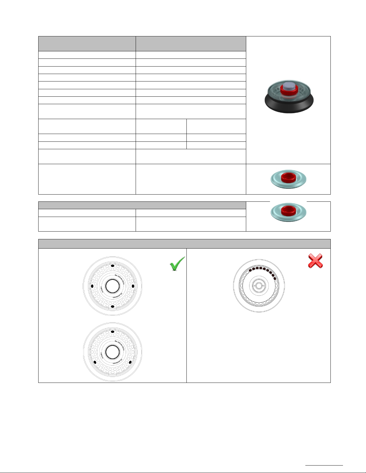
OM0252 | Rev 4 May/2020
Page 56 of 59
NuAire, Inc. | 2100 Fernbrook Lane | Plymouth, MN 55447 | U.S.A | ph: 763.553.1270 | fx: 763.553.0459 | tf: 800.328.3352 | www.nuaire.com
Angle Rotor NU-RA48-2
Rotor
Part number:
NU-RA48-2
Description:
48 x 2 ml Angle rotor
Maximum capacity:
48x 2 ml micro tubes
Maximum load
48 x 10 gr
Micro tube tilt:
45°
Fastening:
ClickSpin system
Maximum rotor speed
15500 rpm
Maximum centrifugal force of the
rotor
26620 xg
Maximum centrifugal
force
AFI-C300 Ventilated
14000 rpm
22132 xg
AFI-C300 Refrigerating
15500 rpm
27129 xg
Maximum radius
99 mm (outer row)
89 mm (inner row)
Lid Part number:
NU-LM2
Description:
Micro tube rotor airtight lid for rotors NURA30-2, NU-RA48-2 and NU-RA16-5
Loading the rotor
Allowed :
Forbidden:
Centrifuge performance Maximum speed
Items included:
Micro tube rotor airtight lid for rotors NURA30-2 and NU-RA48-2
Accessories
Configurations:
(Lid included)
Page 57
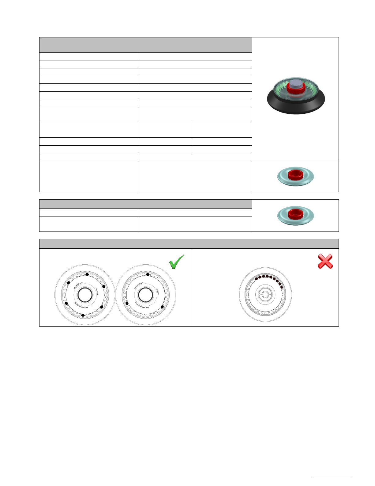
OM0252 | Rev 4 May/2020
Page 57 of 59
NuAire, Inc. | 2100 Fernbrook Lane | Plymouth, MN 55447 | U.S.A | ph: 763.553.1270 | fx: 763.553.0459 | tf: 800.328.3352 | www.nuaire.com
Angle Rotor NU-RA30-2
Rotor
Part number:
NU-RA30-2
Description:
30 x 2 ml Angle rotor
Maximum capacity:
30x 2 ml micro tubes
Maximum load
30 x 10 gr
Micro tube tilt:
45°
Fastening:
ClickSpin system
Maximum rotor speed
16000 rpm
Maximum centrifugal force of the
rotor
27720 xg
Maximum centrifugal
force
AFI-C200 Ventilated
15300 rpm
25350 xg
AFI-C200 Refrigerating
16000 rpm
27720 xg
Maximum radius
97 mm
Part number:
NU-LM2
Description:
Micro tube rotor airtight lid for rotors NURA30-2, NU-RA48-2 and NU-RA16-5
Loading the rotor
Allowed
Forbidden:
Centrifuge performance Maximum speed
Items included:
Airtight lid for rotors NU-RA30-2 and NURA48-2
Accessories
Lid
Configurations:
(Lid included)
Page 58
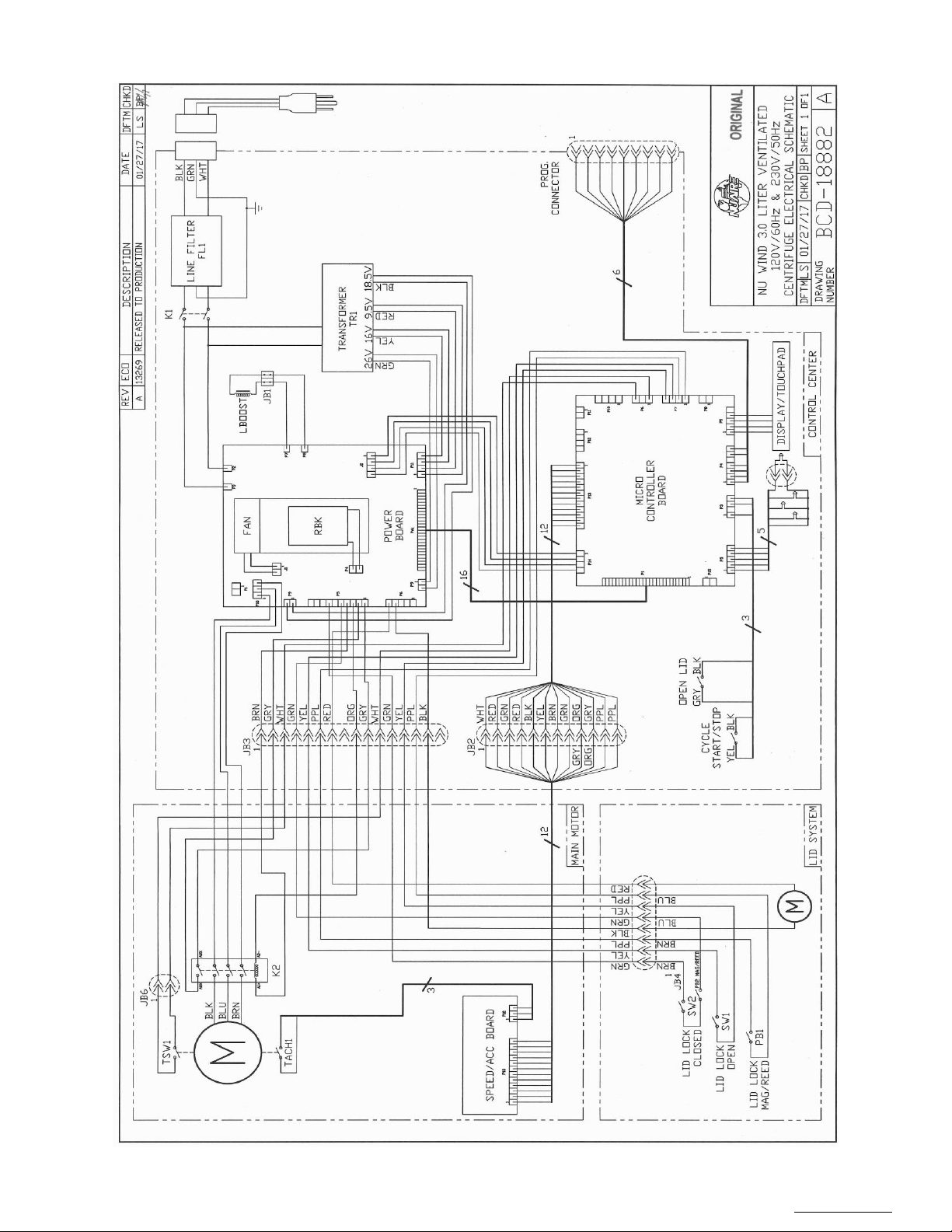
OM0252 | Rev 4 May/2020
Page 58 of 59
NuAire, Inc. | 2100 Fernbrook Lane | Plymouth, MN 55447 | U.S.A | ph: 763.553.1270 | fx: 763.553.0459 | tf: 800.328.3352 | www.nuaire.com
Page 59
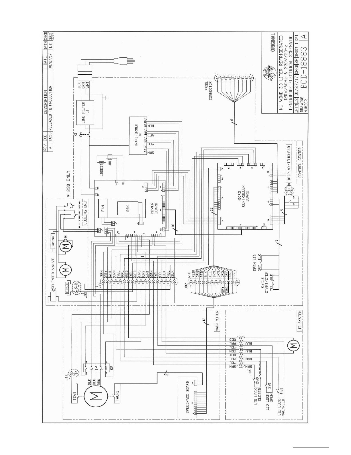
OM0252 | Rev 4 May/2020
Page 59 of 59
NuAire, Inc. | 2100 Fernbrook Lane | Plymouth, MN 55447 | U.S.A | ph: 763.553.1270 | fx: 763.553.0459 | tf: 800.328.3352 | www.nuaire.com
 Loading...