

Page 1
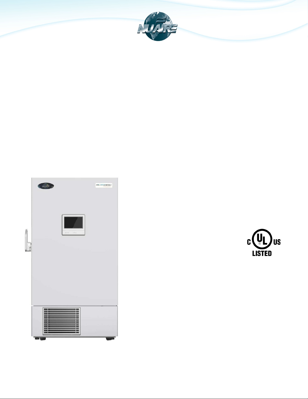
NUAIRE BLIZZARD ULTRA LOW TEMPERATURE
VARIABLE FREQUENCY TOUCHSCREEN FREEZER
NU-99729VFT
PERATION & MAINTENANCE MANUAL
O
OM0299
Series A
Revision 1
December 2020
NuAire, Inc.
2100 Fernbrook Lane
Plymouth, MN 55447
Toll-Free: 1-800-328-3352
Minnesota: (763) 553-1270
Fax: (763) 553-0459
Page 2

Table of Contents
1.0 Packing List .................................................................................................................................. 3
2.0 Precautions for Safe Operation..................................................................................................... 3
2.1 Safety Labels and Precautions............................................................................................................ 3
2.2 Precautions for Safe Operation .......................................................................................................... 4
3.0 Product Features.......................................................................................................................... 7
4.0 Usage Precautions ....................................................................................................................... 8
5.0 Product Installation..................................................................................................................... 10
5.1 Installation Environment .................................................................................................................. 10
5.2 Installation Site ................................................................................................................................ 10
5.3 Preparation Before Use .................................................................................................................... 11
5.4 Initial Startup ................................................................................................................................... 12
5.5 Operation after a Power Outage ...................................................................................................... 13
6.0 Refrigerator Components ............................................................................................................ 14
6.1 Control Panel ................................................................................................................................... 14
7.0 Operation ................................................................................................................................... 15
7.1 Homepage ........................................................................................................................................ 15
7.2 Settings ............................................................................................................................................ 16
7.3 Graph
7.4 Inquiry .............................................................................................................................................. 24
7.5 Message ........................................................................................................................................... 29
7.6 Alarm ............................................................................................................................................... 31
8.0 Cleaning Maintenance................................................................................................................. 31
8.1 Cleaning the Freezer ........................................................................................................................ 32
8.2 Cleaning the Condenser Filter .......................................................................................................... 32
8.3 Defrosting ........................................................................................................................................ 32
8.4 Battery Maintenance ....................................................................................................................... 33
8.5 Disposal of Freezer ........................................................................................................................... 33
8.6 Disposal of Battery ........................................................................................................................... 33
9.0 Optional Accessories ................................................................................................................... 34
9.1 Temperature Recorder..................................................................................................................... 34
9.2 LCO2 Backup Cooling System ........................................................................................................... 34
9.4 Electromagnetic Lock ....................................................................................................................... 35
9.5 Frozen Storage Racks and Storage Boxes ......................................................................................... 36
10.0 Troubleshooting.......................................................................................................................... 37
11.0 Refrigeration and Wiring Diagram ............................................................................................... 38
11.1 Refrigeration Diagram ...................................................................................................................... 38
11.2 Wiring Diagram ................................................................................................................................ 39
12.0 Specifications and Technical Data ................................................................................................ 40
12.1 Specification Table ........................................................................................................................... 40
12.2 Technical Data .................................................................................................................................. 41
12.3 Global Warming Potential ................................................................................................................ 41
............................................................................................................................................... 23
OM0299 PAGE 2 OF 41 REV 1 DECEMBER/2020
Page 3
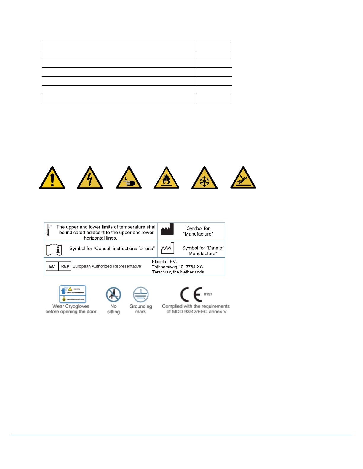
1.0 Packing List
Item
Quantity
Installation and Commissioning Manual
1
User manual/Spacer Installation Methods
1/1
Plastic bag
1
Ice scraper
1
Key 4 Spacer
2
Warning
Electric
Shock
Combustible
Materials
Low
Temperatur
Slippery
Surface
Watch Your
Hands
2.0 Precautions for Safe Operation
Thank you for choosing a Nuaire Ultra Low Temperature (ULT) Freezer. Please read this manual for safe operation
of this product.
2.1 Safety Labels and Precautions
Fingers and
OM0299 PAGE 3 OF 41 REV 1 DECEMBER/2020
Page 4
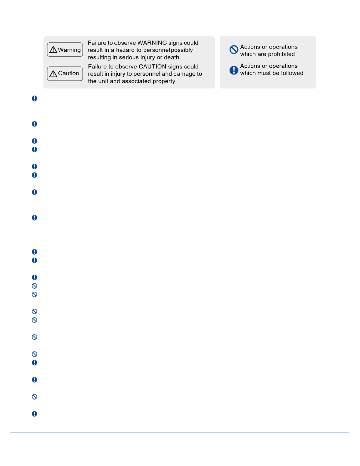
2.2 Precautions for Safe Operation
When the CO2/LN2 backup system is activated, the installation place must be well ventilated. Increased CO2 in
the air may be harmful and even fatal. If the ventilation is poor, other methods should be considered to ensure
safe working environments.
If there is a leakage of petroleum gas or other flammable gas, close the gas supply valve and open doors and
windows to ventilate the air. Do not plug or unplug your freezer unit to avoid potential explosion or fire.
Only professional technicians can install the unit. Failure to do so may cause electricity or fire.
The freezer must be securely installed on a firm floor. Tilted installation may result in the product tipping over,
causing injury and damage.
Only use a dedicated power supply matching the requirement specified on the label to avoid fire and shock.
If the voltage being used is 10% higher than the rated voltage, a regulator with a capacity of 4000 W or higher
must be installed.
If the power cord needs to be extended, the cross-section of the extended cable must be no less than 2 mm² and
no longer than 3 m for products of 208V~230V/50Hz or 208V~230V/60Hz and no less than 3 mm² and no longer
than 3 m for products of 115V~/60Hz to avoid fire or electric shock.
Your ULT unit is equipped with a standard three-prong power plug (grounded) complying with the standard three-
prong socket (grounded) rated 16 A (208V~230V/50Hz or 208V~230V/60Hz) or rated 20A (115V~/60Hz). Removal
of the ground prong is strictly prohibited for safety reasons under any circumstances. The electrical power plug
should be securely plugged into the socket. A loose plug in the socket may cause fire.
The power socket intended for your ULT usage must be grounded to avoid electric shock.
If the socket does not meet this requirement, the condition must be corrected by a qualified technician before
using the ULT unit.
Replacement of any spare parts should be performed by qualified technicians.
Never install your ULT in an unprotected area. If the unit gets wet, there is a danger of electric shock.
Your Blizzard ULT must not be installed in a damp area or an area subjected to water spray. Otherwise this may
reduce the degree of insulation which may cause electrical leakage or electrical shock.
Never directly pour water into the unit. The water may cause electric shock or short circuit.
Do not place any water container or heavy object on top of the unit. A falling object may injure an operator. If the
water spills into the unit, it may damage the insulation thereby causing electric shock.
Never use gas lines, water mains, telephone lines or lightning rods as the grounding device for your ULT unit. This
type of improper grounding may cause electric shock or other danger.
Do not touch any electrical components, switches, or power cord with wet hands. This may lead to electric shock.
When unplugging the power cord from the socket, please grip the plug itself and pull it out. Do not pull the power
cord as this may strip the wires out of the plug thereby causing electric shock and fire.
Should there be any malfunction in the equipment, power off the unit and unplug the power cord from the power
supply. Continuous operation in an abnormal condition may result in electric shock and fire.
Never disassemble, repair, or modify the unit yourself. Any such work carried out by an unauthorized person may
result in fire, or electric shock or injury due to a malfunction.
Before any repair and maintenance of the freezer, please disconnect the power to avoid electric shock or injury
to personnel.
OM0299 PAGE 4 OF 41 REV 1 DECEMBER/2020
Page 5

When repairing and maintaining your freezer, take precautions not to inhale any chemicals or aerosols floating
inside and outside the unit. This may be harmful to your health.
If poisonous, radioactive, or other harmful materials need to be stored in the unit, the equipment should be
located in a safe zone. Improper usage of the equipment with such materials may harm the environment or
operator's health.
If the unit is not in use for a long period of time, make sure the power cord is unplugged. Deteriorated insulation
of the power cord may lead to electric shock or fire.
If the unit is to be stored unused in an unsupervised area for an extended period, ensure that doors are locked
completely with a key to prohibit unauthorized access.
The disposal of the unit should be accomplished by appropriate personnel. The doors should be removed prior to
disposal.
Do not use any non-manufacturer approved electrical components in the freezer.
Never store flammable, explosive or volatile materials in the unit and do not use any flammable spray near the
unit, as this may cause an explosion or fire.
Never store corrosive chemicals with acid or alkaline properties in the unit as this can cause damage to internal
components of the unit.
Do not place any glass container or enclosed container into the freezer. These containers may crack at low
temperatures causing injury to operators
Do not put the packing plastic bag within reach of children as suffocation may result.
Do not climb on top of the unit or place any object on it. Falling equipment may cause injury or property damage.
Do not use any hard objects such as nails and wires to explore any openings or gaps such as air ventilation ports.
Accidental contact between a hard object and a moving part may result in electric shock or injury.
Do not use electrical appliances inside the chamber of the appliance unless they are recommended by the
manufacturer.
The appliance must be positioned so that the plug is accessible.
The power plug is used as the disconnecting device.
The appliance must be placed on a solid and flat surface, or excessive vibration and noise may be produced when
the appliance in operation.
If the power cord is damaged, it must be replaced by a qualified technician to avoid an electrical hazard.
To avoid the risk of electric shock, this equipment must only be connected to a supply main with protective
ground.
There should be at least 1 ft (30 cm) space between the surrounding walls and the freezer for ventilation.
Equipment cannot run in the condition of rich O2 and flammable gas or liquid.
After restarting your unit from a power outage or shutdown, ensure that all settings are correct. Accidental
changes in settings may damage the stored products.
In the event of a power outage and recovery, be sure to wait for at least 5 minutes before turning the unit on
again to avoid damage to the compressors and refrigeration system.
The air filter for the condenser should be cleaned regularly. A dirty filter could cause a malfunction or the freezer
temperature to rise.
During any repair operations, gloves should be worn to prevent getting injured by sharp edges or corners.
Do not use bare hands to directly handle any stored products. The cold temperature of the products and the
interior walls may cause frostbite.
Hold firmly onto the handle to close the door to avoid pinching your hands.
Do not tilt the unit more than 45 degrees when moving the unit.
When moving the unit, make a clear path to avoid injury to personnel and damage to the unit.
Do not attempt to use the handle to lift or move the unit to avoid damaging the freezer or injuring personnel.
Maximum loading on each shelf should be no more than 100 Lbs. (50 kg) and total loading for whole unit should
be no more than 400 Lbs. (200 kg). Heavier loads may cause damage to the shelving system.
OM0299 PAGE 5 OF 41 REV 1 DECEMBER/2020
Page 6

Keep ventilation openings, in the appliance enclosure or in the built-in structure, clear of obstructions.
Do not use mechanical devices or other means to accelerate the defrosting process.
Do not damage the refrigerant circuit.
Unauthorized opening of the top cover of the control cabinet is prohibited to prevent damage to the inside
components or injury to the operator.
Turn the battery switch on before starting the unit, do not arbitrarily turn it off.
When the ULT unit has been placed in a storage or not in use for a long time, the battery should be tested for low
capacity because the battery may have already fully discharged. Should this occur, turn on the battery switch and
run the unit for about a week to fully charge up the battery.
OM0299 PAGE 6 OF 41 REV 1 DECEMBER/2020
Page 7

3.0 Product Features
This product is suitable for the ultra-low temperature storage of products in applications such as clinical,
pharmaceutical, scientific research, and epidemic institutions. It also can be used in blood stations, hospitals,
centers for disease prevention and control, science and research institutions, electronic and chemical laboratories,
biomedical engineering institutions, and open sea fishery companies to store red blood cells, viruses, germs, skin,
bones, bacteria, sperm, biological products, electronic components, and low temperature testing samples of
special products, etc.
• Temperature control
o Temperature is controlled by computer and numerically displayed and regulated in units of 0.1°C;
temperature range: -40°C to -86°C.
• Safety system
o Various malfunction alarms (high/low temperature alarm, power failure alarm, probe failure
alarm, hot condenser alarm, high ambient temperature alarm, door ajar alarm, low battery
alarm).
o Two types of alarms: Audible (buzzer sound) and Visual (flashing light).
o Multiple levels of protection are standard including passcode and time-delayed start.
o All components are electrically grounded.
• Refrigeration system
o Optimized multiple refrigeration technology with top brand frequency compressors offering
better refrigeration capability.
o Excellent temperature preservation layer providing optimal temperature preservation effect.
o Exclusive sealing structure of multiple doors and hot tubing for condensation prevention can
reduce the frost effectively.
• Ergonomic design
o Touchscreen display to indicate freezer temperature, ambient temperature, and input voltage.
Control panel to set the high/low temperature alarm and inner temperature. All malfunction
alarms are also shown on the display.
o Designed with adjustable shelves, suitable for product storage.
o Safety lock design prevents accidental opening of doors.
o Installation in broad range of ambient temperature range of 10 ℃ to 32 ℃ environment.
o Unique all-in-one latch design and compact caster features allow ease of operation and
maneuvering.
o Condensing fan motors are automatically controlled to turn on and off for energy saving.
o Network and remote alarm contacts are available for convenient connection and communication.
NOTE: Not all models have all features mentioned above. For specific features, please refer to the specification
table of each specific model. Due to the product improvement, the Nuaire ULT Freezer you get may not
be completely consistent with the illustration in the manual. The contents of this manual are subject to
changes without notice.
OM0299 PAGE 7 OF 41 REV 1 DECEMBER/2020
Page 8

4.0 Usage Precautions
• While the unit is operating, the door frame will become slightly warm. The embedded hot gas halo tube
provides latent heat to prevent condensation to from on the door frame.
• Before samples are loaded into a freezer, make sure the unit has reached the set temperature. Samples should
be loaded into the freezer in batches. Each batch should be no more than 1/3 of the freezer capacity. This
process allows the freezer to pulldown the temperature in a reasonable time without damaging the
compressor.
• The temperature display indicates the temperature where the temperature sensor is mounted inside the unit
chamber, which may vary from the temperature at the center of the freezer, but it will gradually reach the
actual temperature of the freezer over time.
• Two access ports are available for testing in the back of the freezer. Thermocouple wires can go through the
port holes to reach the interior of the freezer for temperature mapping. The gap of the holes should be sealed
with insulation materials so that the interior temperature is not influenced by the ambient temperature.
• When cleaning the unit, mild and neutral detergent solution should be used. Never use a hard wire brush,
acid, gasoline, detergent powder, polished powder or hot water for cleaning. These tools and materials can
damage the paint and coating of the unit. Particularly, never use gasoline or a solution with volatile chemicals
to clean plastic or rubber parts.
• After the freezer runs for some time, a layer of frost usually forms on the interior wall and inner doors. When
the frost gets too thick, the refrigeration effect can be impaired. Energy consumption will increase. If the
thickness reaches 3/16” (5 mm), please use the supplied scrapper to remove the frost.
• Before removing the frost, temporarily transfer the stored samples to another freezer. This is so that the
temperature does not rise in the unit and damage the samples.
• Behind the interior walls, there are many refrigeration tubes. Do not use a knife, an ice pick, or a screwdriver
to cut ice and frost. This may damage not only the liner but also the refrigeration tubes.
• If the freezer is not in use for a long time, please turn off the power and switch off the backup battery. The
power cord should be unplugged.
• Federal Communications Commission (FCC) Interference Statement
o This equipment has been tested and found to comply with the limits for a Class B digital device,
pursuant to Part 15 of the FCC Rules.
o These limits are designed to provide reasonable protection against harmful interference in a
residential installation. This equipment generates, uses and can radiate radio frequency energy and,
if not installed and used in accordance with the instructions, may cause harmful interference to radio
communications.
o However, there is no guarantee that interference will not occur in a particular installation. If this
equipment does cause harmful interference to radio or television reception, which can be determined
by turning the equipment off and on, the user is encouraged to try to correct the interference by one
of the following measures:
- Reorient or relocate the receiving antenna.
- Increase the separation between the equipment and receiver.
- Connect the equipment into an outlet on a circuit different from that to which the receiver
is connected.
- Consult the dealer or an experienced radio/TV technician for help.
• This device complies with Part 15 of the FCC Rules. Operation is subject to the following two condition:
1. This device may not cause harmful interference
2. This device must accept any interference received, including interference that may cause undesired
operation.
OM0299 PAGE 8 OF 41 REV 1 DECEMBER/2020
Page 9
FCC Caution: Any changes or modifications not expressly approved by the party responsible for
compliance could void the user’s authority to operate this equipment.
• RF exposure warning
This equipment complies with FCC radiation exposure limits set forth for an uncontrolled environment. This
equipment must be installed and operated in accordance with provided instructions and the antenna(s) used
for this transmitter must be installed to provide a separation distance of at least 20 cm from all persons and
must not be collocated or operating in conjunction with any other antenna or transmitter.
This equipment complies with ISED RSS-102 radiation exposure limits set forth for an uncontrolled
environment. This equipment should be installed and operated with a minimum distance of 20cm between
the radiator and any part of your body.
Pour se conformer aux exigences de conformité CNR 102 RF exposition, une distance de séparation d'au moins
20 cm doit être maintenue entre l'antenne de cet appareil ettoutes les personnes.
Contains FCC ID: 2ASR8NFCV3, 2ASR8SC3832.
This device contains licence-exempt transmitter(s)/receiver(s) that comply with Innovation,
Science and Economic Development Canada’s licence-exempt RSS(s). Operation is subject to the following two
conditions:
1. This device may not cause interference.
2. This device must accept any interference, including interference that may cause undesired operation
of the device.
L’émetteur/récepteur exempt de licence contenu dans le présent appareil est conforme aux CNR
d’Innovation, Sciences et Développement économique Canada applicables aux appareils radio exempts de
licence. L’exploitation est autorisée aux deux conditions suivantes :
1. L’appareil ne doit pas produire de brouillage;
2. L’appareil doit accepter tout brouillage radioélectrique subi, même si le brouillage est susceptible d’en
compromettre le fonctionnement.
Do not dispose of electrical appliances as unsorted municipal waste, use separate collection facilities.
Contact your local government for information regarding the collection systems available.
OM0299 PAGE 9 OF 41 REV 1 DECEMBER/2020
Page 10
5.0 Product Installation
5.1 Installation Environment
• Ambient temperature: 10°C to 32°C. The ideal temperature is 18°C to 25°C. If necessary, use an air-
conditioning system to achieve the requires ambient condition.
• Environment humidity: less than 57% RH.
• Installation area should be clean and free from large amounts of dust.
• Installation area should be free from vibration and shocks.
• Highest recommended elevation for safe usage: 2,000 m above sea level.
• Input voltage: rated voltage ± 10%.
o
5.2 Installation Site
For the equipment to achieve optimal operating conditions, an intended installation location should satisfy the
following requirements.
• Do not install the unit in a confined space. The doorway should be large enough for the unit to freely be
transferred in or out of the room if necessary. This is to allow the unit to be repaired easily and timely to avoid
damage to property.
• The location for installation should be flat and firm.
• There should be good ventilation and no direct sunlight.
• The freezer unit cannot share the same power socket with other equipment. The power plug should be
securely connected to the power socket.
• The power cord for the freezer should not be twisted or pinched.
• If the power cord needs to be extended, the cross-section of the extended cable must not be no shorter than
2 mm (14 gauge wire) and no longer than 10 ft [3 m].
• Before using the freezer, check the voltage supply. A voltage stabilizer to deliver rated voltage ± 10% is
recommended for areas in which the voltage is known to be unstable. The voltage stabilizer should be rated
at least 4000W.
• The freezer must be grounded.
• If the power socket is connected with a ground terminal, make sure to inspect it for proper connection before
using the equipment.
An ULT is sensitive to its operating environment. If the unit is not installed in the conditions
mentioned above, it may not operate reliably.
o
The unit is intended for indoor use only. Improper use may result in damage to the unit or injury.
Do not ground the freezer through gas lines, water mains, telephone lines and lightning rods,
o
as this may lead to electric shock.
o
After installation, the power plug must be easily accessible to unplug in case of an emergency.
Nothing should block ventilation port of the freezer.
OM0299 PAGE 10 OF 41 REV 1 DECEMBER/2020
Page 11
5.3 Preparation Before Use
1. Remove packing material and straps.
2. Check the supplied accessories
• Check the items in the packing box according to the packing list. If anything does not match, contact
Nuaire support immediately.
3. Placement
• This freezer is for indoor and dry conditions only.
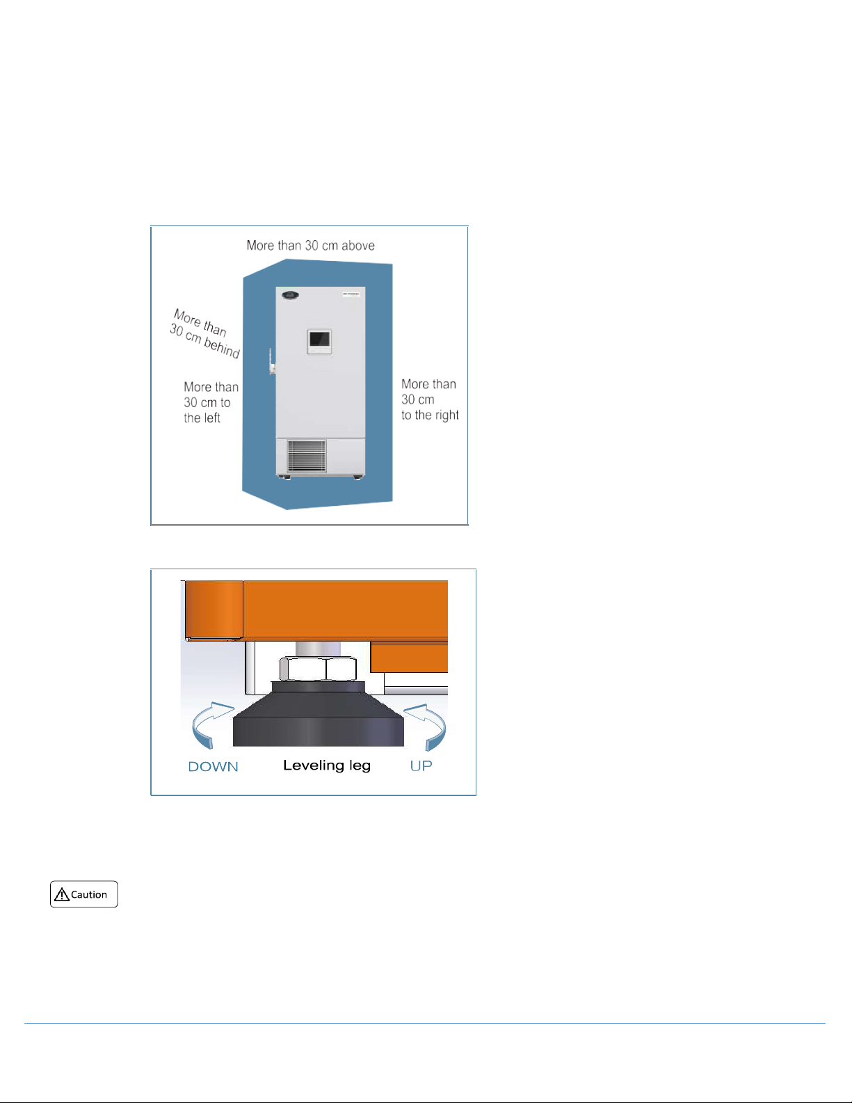
• Reserve at least 1 ft [30cm] of clearance on each side of the freezer for proper ventilation.
4. Adjust Levelling Legs
• Rotate the levelling legs clockwise to extend them to level the unit.
5. Acclimation Period
• After adjusting and cleaning the unit, do not turn on the power. The freezer needs to acclimate to its
surroundings for at least 24 hours to ensure proper operation.
o To handle the freezer before unpacking, forklift or package carrier may be used. If the forklift is used,
o After unpacking, you may push wheels for maneuvering.
o During handling, do not tip the freezer at more than 45° to avoid tipping.
it shall be inserted at the bottom of blocking from the front or back of the freezer to move the
freezer. If the package carrier is used, it shall pick up at the bottom of blocking and can only pick up
the side of the freezer.
OM0299 PAGE 11 OF 41 REV 1 DECEMBER/2020
Page 12
5.4 Initial Startup
While keeping the unit empty, plug in the power cord
Connect the freezer to the power supply, turn on the
battery switch.
If the unit has a backup cooling system (optional) turn
Once the unit is confirmed to be operating properly, it is ready to be loaded with samples. In
1
2
3
4
5
6
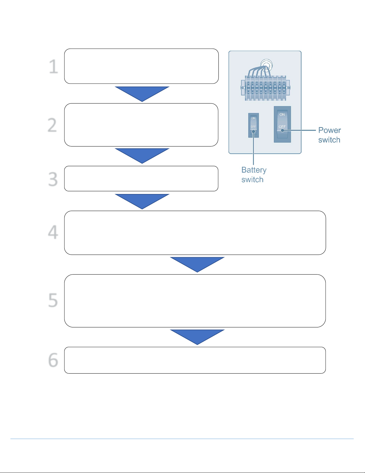
When powering on the unit for the first time, follow the procedures below:
to dedicated power socket that meets all electrical
requirements.
power switch located on the side of the freezer (as in
the illustration on the right), and then turn on the
off the backup system.
Set the unit to desire temperature: Do not load the unit with any samples. Power up the unit
to let it run down to -60°C. Let it run at -60°C for 8 hours then lower it to -80°C. Observe the
unit performance for 24 hours for normal cycling to ensure that it is working properly.
principle, the freezer unit should be set at about 3°C above the desired temperature. For
example, if the storage temperature is -60°C, set the unit at -57°C. Load the unit with samples
in batches of less than 1/3 of the unit’s capacity. Make sure that the unit is capable of cycling
for more than 8 hours.
If the unit has a backup cooling system (optional), turn it on.
OM0299 PAGE 12 OF 41 REV 1 DECEMBER/2020
Page 13
• If the freezer temperature warms up, and the issue can’t be resolved within a short time, please transfer the
stored products to another freezer to avoid potential damage.
• Before placing samples in the freezer for storage, check the freezer temperature to make sure the
temperature meets the storage requirement for the samples. This is to prevent any potential damage to the
samples due to incorrect storage temperature.
• Since it takes time to remove lower the temperature of the stored product, there can be a difference between
the set temperature and the displayed temperature. This difference will get smaller as the set point is lowered.
Samples must be loaded in batches, while gradually decreasing temperature setting. The process should be
repeated until the final temperature is reached.
• Do not use any unauthorized mechanical tools or other means to accelerate the defrosting process.
• Do not damage the refrigeration circuit.
• Do not use any unapproved electrical components in the freezer.
It is not recommended to load excessive amounts of samples into the unit at one time. Overloading may result
in inadequate performance. The freezer and the compressors can become overheated and malfunction.
5.5 Operation after a Power Outage
Your ULT freezer control settings are stored in its memory system. Should there be power outage and
recovery, the unit can resume its operation based on the previous settings.
o In the event of a power outage and recovery, be sure to wait for at least 5 minutes before turning the unit
on again to avoid damaging the compressors and refrigeration system.
o If the unit is not in use for a long period of time, make sure the power cord is unplugged. Deteriorated
insulation of the power cord may lead to electric shock or fire.
OM0299 PAGE 13 OF 41 REV 1 DECEMBER/2020
Page 14
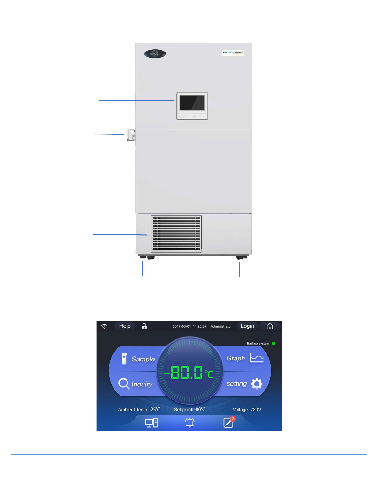
6.0 Freezer Components
LCD Touchscreen
Door Handle
Component
Access Panel
Caster
(With Lock)
6.1 Control Panel
Leveling Leg
OM0299 PAGE 14 OF 41 REV 1 DECEMBER/2020
Page 15
7.0 Operation
7.1 Homepage
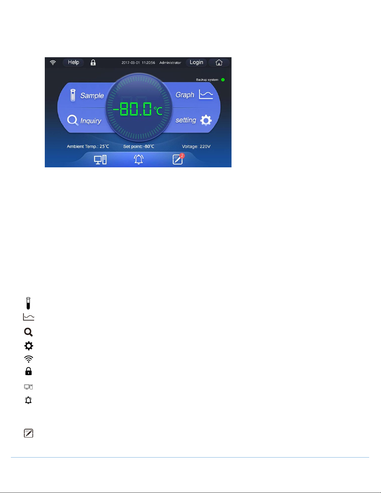
The Homepage can display the real-time internal temperature, ambient temperature, set point, input voltage,
network state, user login status, freezer health status, temperature graph, and message/ note book, backup
system state (optional), electromagnetic lock state (optional), etc.
Icon of real-time internal temperature:
The icon reflects the health status of the freezer by changing colors:
Green: System is operating normally.
Yellow: System occurs a general alarm that does not affect the internal temperature. Example, ambient
temperature alarm.
Red: System has a serious alarm affecting the internal temperature. Example, power failure alarm.
Homepage Symbols:
Tap to enter the sample management interface
Tap to enter the graph viewing interface, where temperature records can be downloaded
Tap to enter the information search interface
Tap to enter the freezer setting interface
Indicates that the network is enabled
Indicates that the electromagnetic lock has been installed and is in the locked state. (Optional)
Tap to enter the configuring the sample bank server address and port interface.
Tap this button to enter the Alarm Record interface where the alarm record can be downloaded. When occurring
a serious alarm that affects the temperature inside the freezer, this icon turns Red, and when occurring a general
alarm not affecting the internal temperature, the icon turns Yellow. The buzzer can be cancelled after tapping.
Click to enter the message and notebook interface.
OM0299 PAGE 15 OF 41 REV 1 DECEMBER/2020
Page 16
Backup system Indicates that the Backup System status:
Green: Backup System is running.
Grey: Backup System is off.
7.2 Settings
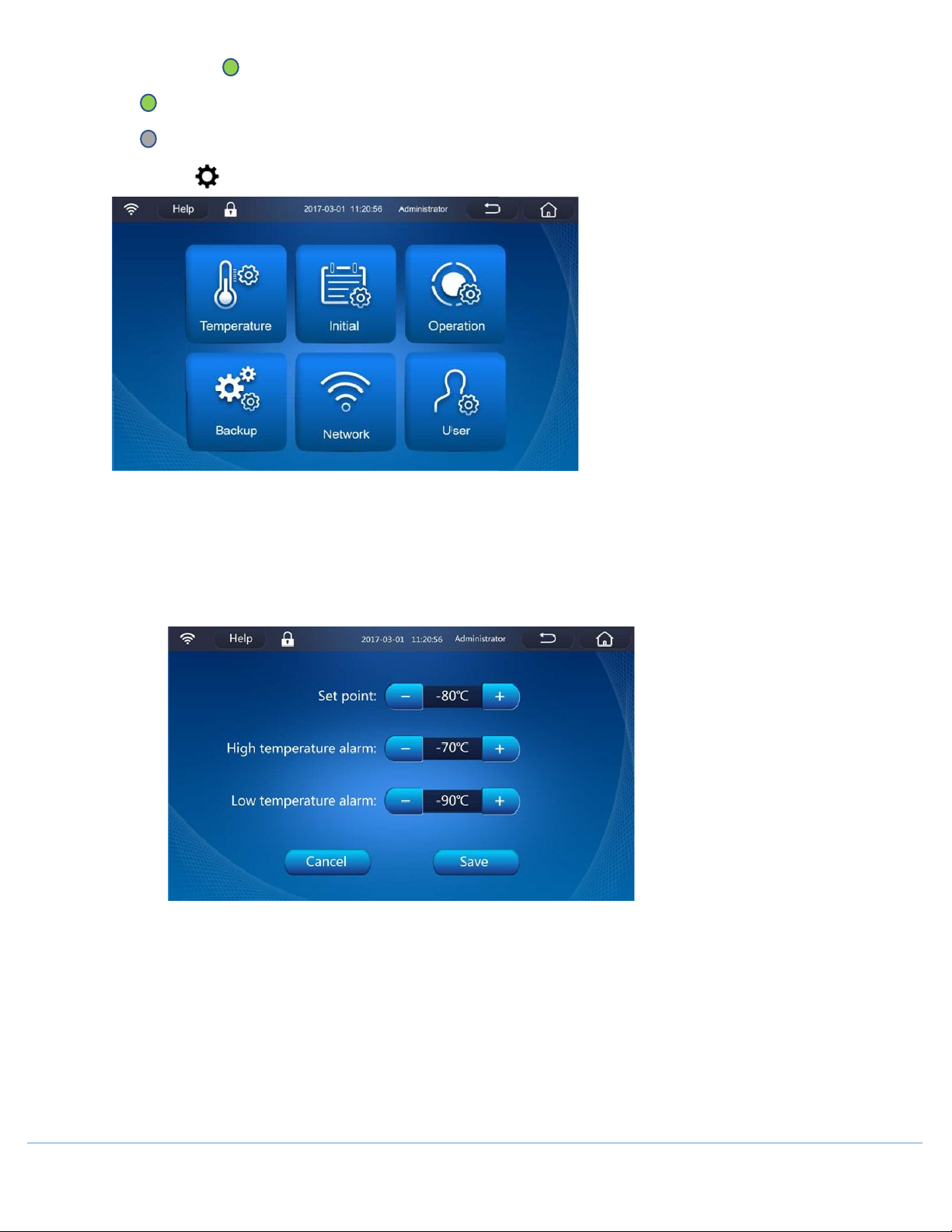
• [Temperature]
Set the internal temperature and high- / low- temperature alarm value. Select the internal temperature
value or high-/ low- temperature alarm value to be set, and then use the button of “+”/ “-” for adjustment
(You can also pop up a value selection box by clicking the value and selecting the value by scrolling the
selection box up and down). Click Save to finish settings.
[Set Point]:
Use to set the required temperature inside the freezer, with the adjustable range of -10℃ ~ -86℃.
[Low temperature alarm]:
Use to set the alarm value of low temperature alarm inside the freezer, with the adjustable range of 15℃~-99℃, which needs to be lower than or equal to the internal temperature value minus 5℃. When
the set value of internal temperature is changed, if the low temperature alarm value is not lower than or
equal to the temperature value inside the freezer for more than 5℃, the low temperature alarm value
will be automatically adjusted to the set value of internal temperature - 5℃.
OM0299 PAGE 16 OF 41 REV 1 DECEMBER/2020
Page 17
If the low temperature alarm value is lower than or equal to the temperature value inside the freezer for
more than 5℃, the low temperature alarm value will not change.
[High temperature alarm]:
Use to set the alarm value of high temperature alarm inside the freezer, with the adjustable range of 0℃
~-81℃, which needs to be more than or equal to the internal temperature value plus 5℃. When the set
value of internal temperature is changed, if the high temperature alarm value is not more than or equal
to the temperature value inside the freezer for more than 5℃, the high temperature alarm value will be
automatically adjusted to "the set value of internal temperature +5℃.
If the low temperature alarm value is lower than or equal to the temperature value inside the freezer for
more than 5℃, the low temperature alarm value will not change.
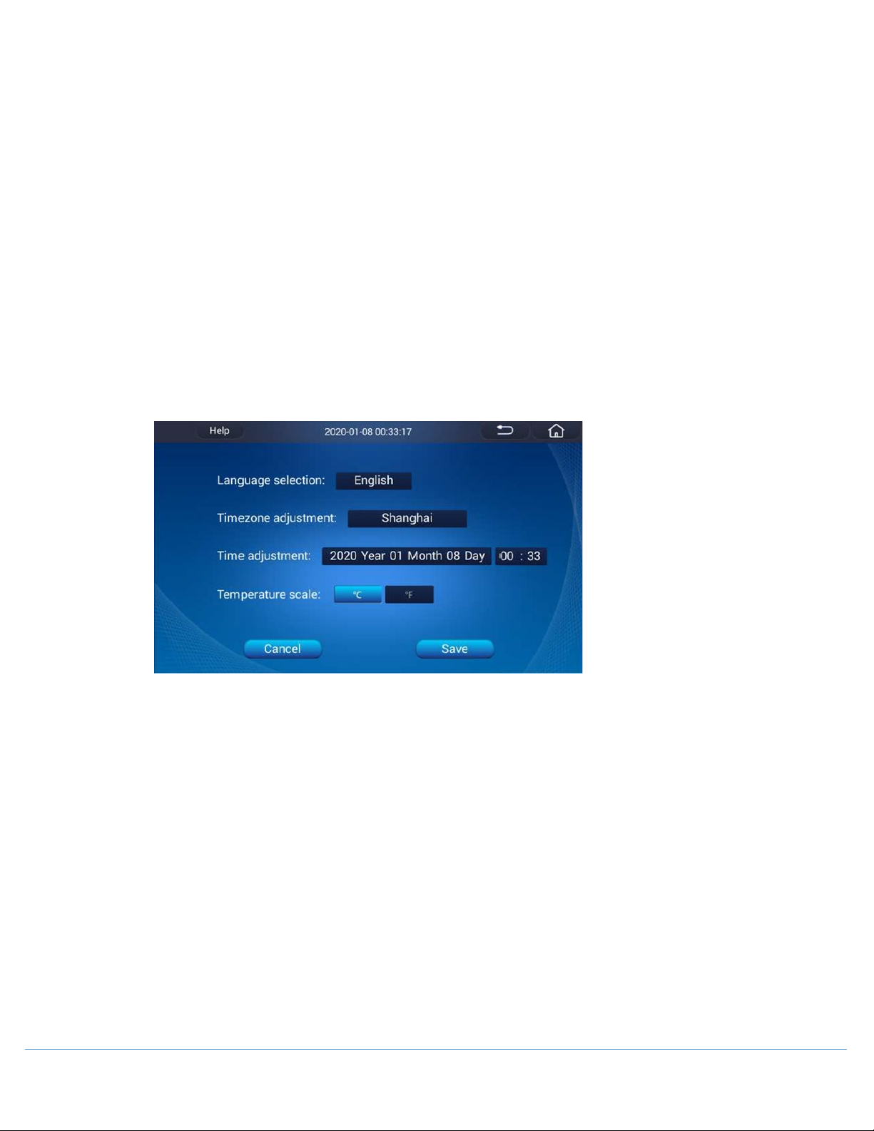
• [Initial]
Tap to set the language, date, time. Click any one value to pop up a selection box, and then you can select
more values by sliding the values in the selection box up and down. When the setting is complete, click
"Save", and then you can see that the time in the upper middle of the screen will be synchronized to the
set value
[Language Selection]:
Select the language.
[Timezone Adjustment]:
Select the current location’s timezone.
[Time Adjustment]:
Set the time value to the local actual time. The default value is read from the main control board. If there
is no communication with the main control board, the last displayed time shall be the default value. NOTE:
If the time value does not match the local time, it will affect the time display of the curve.
[Temperature Scale]:
Set the temperature standard, Celsius (℃) or Fahrenheit (℉).
OM0299 PAGE 17 OF 41 REV 1 DECEMBER/2020
Page 18

• [Operation]
Tap to set the alarm volume, screen brightness, screen auto-lock, auto-logout time, operational mode,
account login mode, time delay to alarm, default display range of graph, time delay to start, ambient
temperature alarm, time to door opening alarm, update and reboot.
[Alarm Volume]:
Adjust the slider to decrease (to the left) or increase (to the right) the volume of the alarm.
Tap to "Mute".
[Screen Brightness]:
Adjust the slider to decrease (to the left) or increase (to the right) the brightness of the LCD screen.
[Screen Auto-Lock]:
Tap to set how long before the screen will enter the sleep state for protection after having not clicked it
to extend the service life of the screen, with the default value of 5min. Selectable options include: 5min,
10min, 15min, 20min, and Never. if you choose “Never” the screen will enter the screen saver 5 minutes
later. After the screen sleep, click anywhere on the LCD screen, it will automatically wake up and enter
the homepage.
Choose "never" after no operation within 5 mins the display will enter screensaver mode.
[Auto-Logout Time]:
Tap to set how long the logged-in account will automatically log out after having not carried out any
operation to protect the account security, with the default values of 5min. Selectable options include:
5min, 10min, 15 min and 20min.
[Operational Mode]:
High performance: Provides high temperature uniformity and stability of the temperature inside the
freezer to store the sample with a very strict temperature control requirements of the internal
temperature.
Energy saving: Compared with high-performance mode, it can save up to 10% of electricity. This mode
has less strict temperature control requirements of the internal temperature.
• [Backup]
Tap to turn the backup system ON/OFF, type of backup system, and injection temperature, and projected
injection time. It can set when connecting with backup system but cannot set when there is no backup
system, and the display will show in gray.
OM0299 PAGE 18 OF 41 REV 1 DECEMBER/2020
Page 19
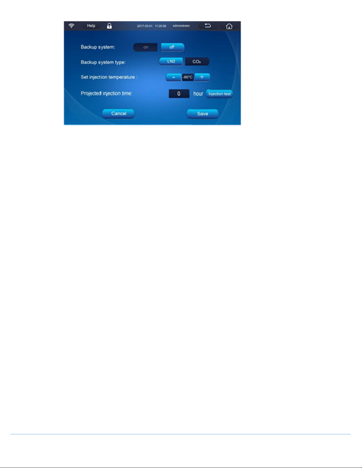
[Backup System]:
Tap to turn the backup system ON/OFF (optional), click "On"; and then click "Off" after the completion of
use.
[Backup System Type]:
Liquid Nitrogen (LN2) or Liquid Carbon Dioxide (LCO2)
[Set Injection Temperature]:
Set the temperature when the backup system starting spraying:
Liquid nitrogen (LN2), the default temperature is -70℃, with the adjustable range of 0 ~-100 ℃.
Carbon dioxide (LCO2), the default temperature is -70 ℃, with the adjustable range of 0 ~-70℃.
NOTE: The set spraying temperature cannot to be lower than the high-temperature alarm value. If the
set spraying temperature is lower than the high-temperature alarm value, it cannot be saved.
[Project Injection Time]:
When installing a backup system, the user can fill enter the estimated usable time of the backup system.
When needed to confirm the remaining conditions after the backup system has been used, the user can
query its cumulative spraying time, and then judge the usage conditions of the backup system through
the difference between these two.
[Injection Test]:
When the temperature inside the freezer does not reach the set spraying temperature, you can tap
[Injection test] to simulate the spraying conditions to confirm whether the spraying system can be
normally used. If the displayed temperature inside the freezer is greater than the set temperature, after
pressing the button of “Injection test", the displayed temperature is unchanged, and the indicator light of
backup system on the homepage is ON; at this time, control to open the solenoid valve for spraying, and
stop the spraying 10 seconds later. If he displayed temperature inside the freezer is less than the set
temperature, after pressing the button of “Injection test", the displayed temperature changes rapidly to
the set temperature; at this point, control to open the solenoid valve for spraying, and stop the spraying
10 seconds later; after that, the displayed temperature will return back to the actual temperature inside
the freezer.
OM0299 PAGE 19 OF 41 REV 1 DECEMBER/2020
Page 20
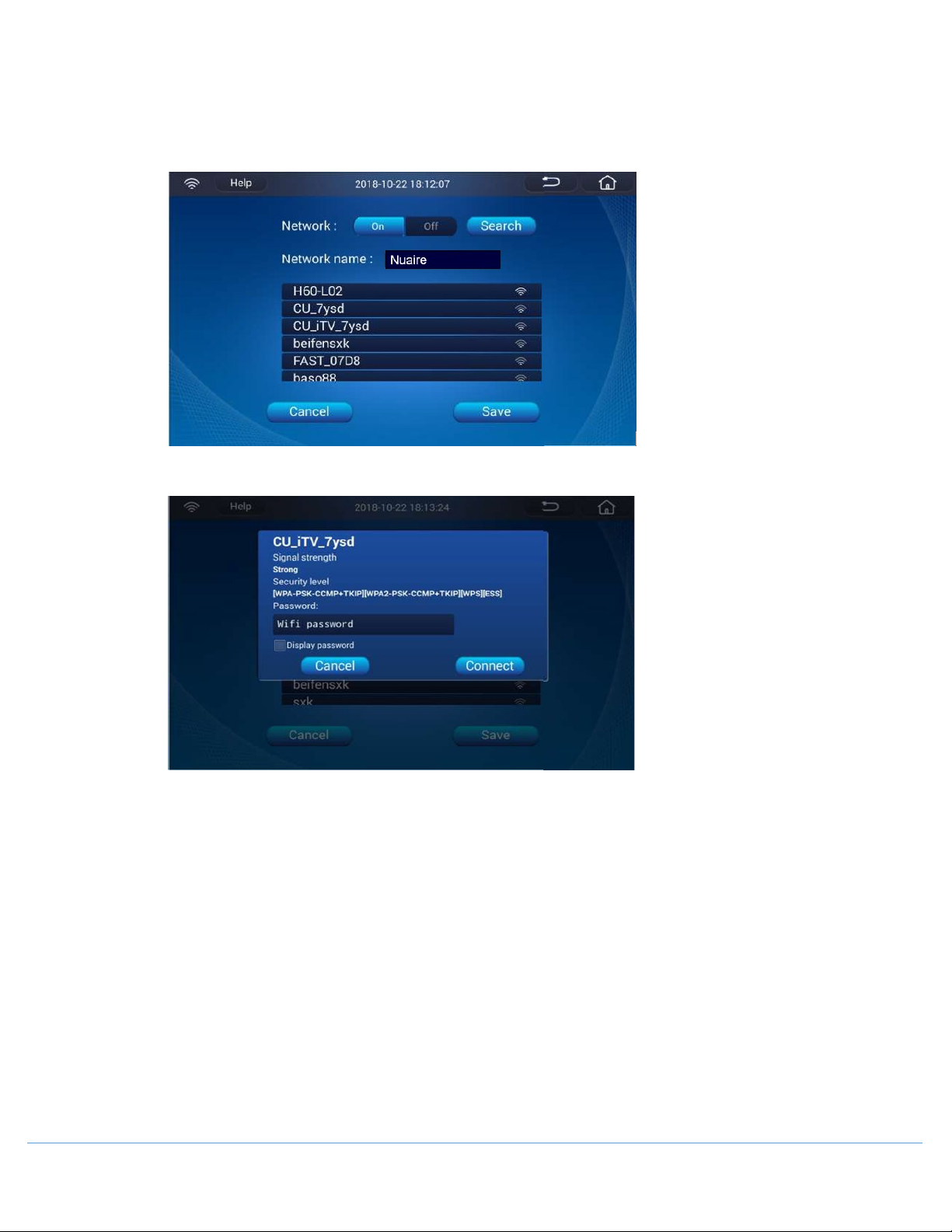
• [Network]
Tap to set the network ON/OFF : After the network search is completed, click the corresponding network,
and enter a password for login, then connect to the network successfully. A Wi-Fi connections is
recommended so that the touch screen can be remotely updated.
[Network Name]: Connected Wi-Fi name
OM0299 PAGE 20 OF 41 REV 1 DECEMBER/2020
Page 21
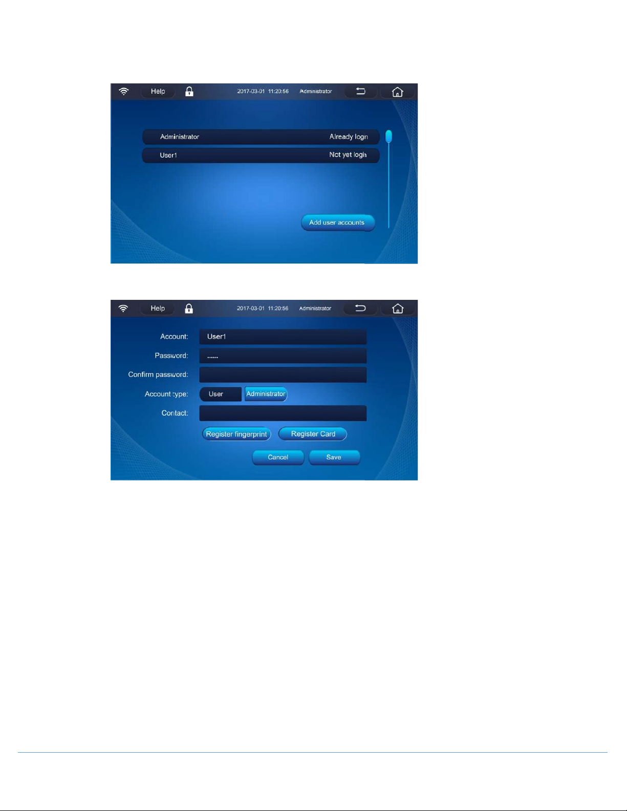
• [User]
Tap to add, edit, delete user accounts, and set user account permissions.
[Add User Accounts]:
.
[Account]: Create an account name.
[Password]: Create a password for the account.
[Confirm Password]: Enter password again to confirm.
[Account Type]:
User: Normal users can only view, query and save the freezer's information, as well as use message and
notebook functions, but cannot change the freezer settings.
Administrator: Administrators have all the functions of a normal user and can change the settings.
[Contact]: Enter contact information (not required).
[Register Fingerprint] (Optional):
When using a fingerprint lock, click [Register fingerprint] to pop up the prompt fingerprint registration,
and then complete the registration of fingerprint on the freezer. After that, the user can open the door
by using the fingerprint or log in the account in the authorization mode. When unlocking the lock, press
the fingerprint directly; when logging in an account, select [Register fingerprint] on the login screen.
OM0299 PAGE 21 OF 41 REV 1 DECEMBER/2020
Page 22
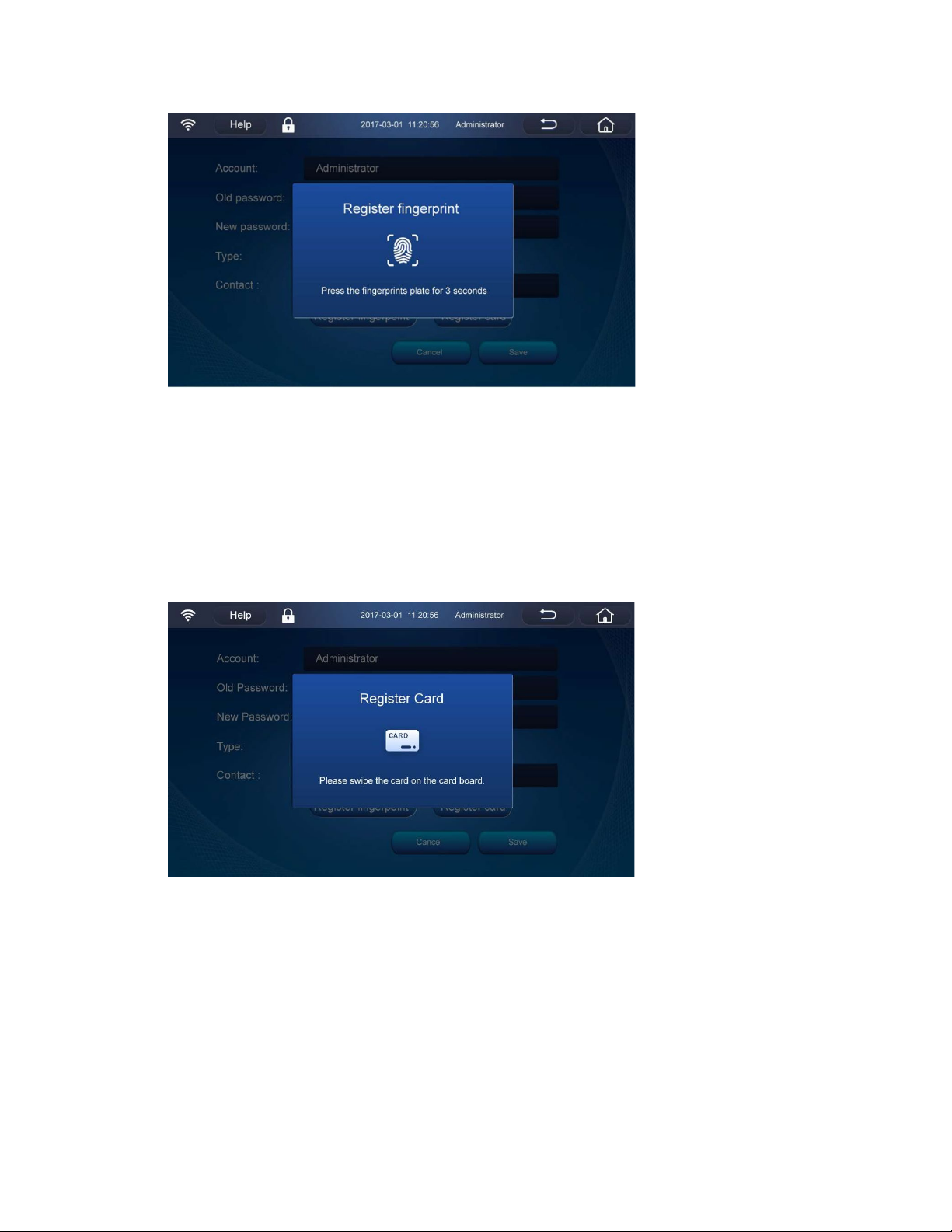
When the electromagnetic lock is not used, the registered fingerprint can be used for account login on
the login interface under the authorization mode.
[Register Card] (Optional):
When using a card-punching lock, click [Register Card] to prompt the card registration, and then
complete the registration of IC card on the freezer. After that, the user can open the door by
punching the card or log in the account in the authorization mode. When unlocking the lock, punch
the card directly in the unlocking zone; when logging in an account, select [Register Card] on the
login screen.
When the electromagnetic lock is not used, the registered card can be used for account login on the
login interface.
[Delete]:
Select an existing account, and then tap it for login to delete the existing account.
OM0299 PAGE 22 OF 41 REV 1 DECEMBER/2020
Page 23
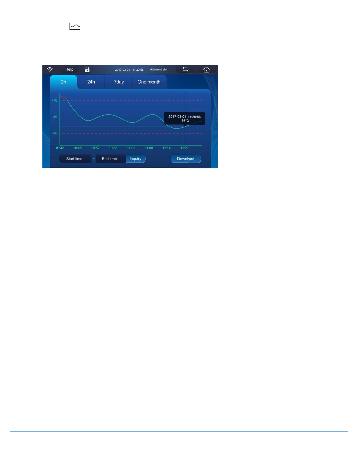
7.3 Graph
View the graph of temperature inside the freezer, and it can be used to select the graph within the selected time
period and then download the temperature record. In addition, the graph that exceeds the alarm value of highand low- temperature will be shown in red.
[2h]: View the temperature graph of the last 2 hours (Default. The default display range of graph can be
modified in the operation settings).
[24h]: View the temperature graph of the last 24 hours.
[7day]: View the temperature graph of the last 7 days.
[One month]: View the temperature graph of the last 1 month
Graph Elements: The middle line is the line of the set temperature inside the freezer
the upper & lower lines are high-/low- temperature alarm value, respectively.
NOTE: The graph can be scaled by sliding the screen.
Tap anywhere on the graph to view the temperature value at a fixed point.
[Inquiry]: Input both the starting time and the ending time, and then tap [Inquiry] to view the temperature
graph in the desired interval.
NOTE: If the interval is more than one month, the graph cannot be viewed.
[Download]: Input both the starting time and the ending time, and then [Download] to download the
temperature data within this interval through USB.
NOTE: If no interval is entered, all temperature data will be downloaded by default.
Data can be exported in CSV or PDF.
NOTE: When you choose PDF format at the interval between the start time and end time cannot exceed 7 days.
OM0299 PAGE 23 OF 41 REV 1 DECEMBER/2020
Page 24
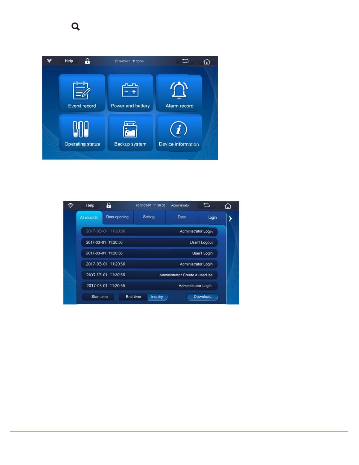
7.4 Inquiry
This page has six query buttons: Event Record, Power and Battery, Alarm Record, Operating Status, Backup System
and Device Information.
• [Event Record]:
Tap to query the records of Door Opening/Closing, Setting & Modification, Data Upload/Download and
Account Login/Logout.
[Inquiry]: Input both the starting time and the ending time, and then tap [Inquiry] to view the
corresponding records in the desired interval.
[Download]: Input both the starting time and the ending time, and then [Download] to download the
corresponding records within this interval through USB.
• [Power and Battery]:
Tap to view both the main battery and the backup system battery's input voltage, output voltage and
remaining battery level
OM0299 PAGE 24 OF 41 REV 1 DECEMBER/2020
Page 25
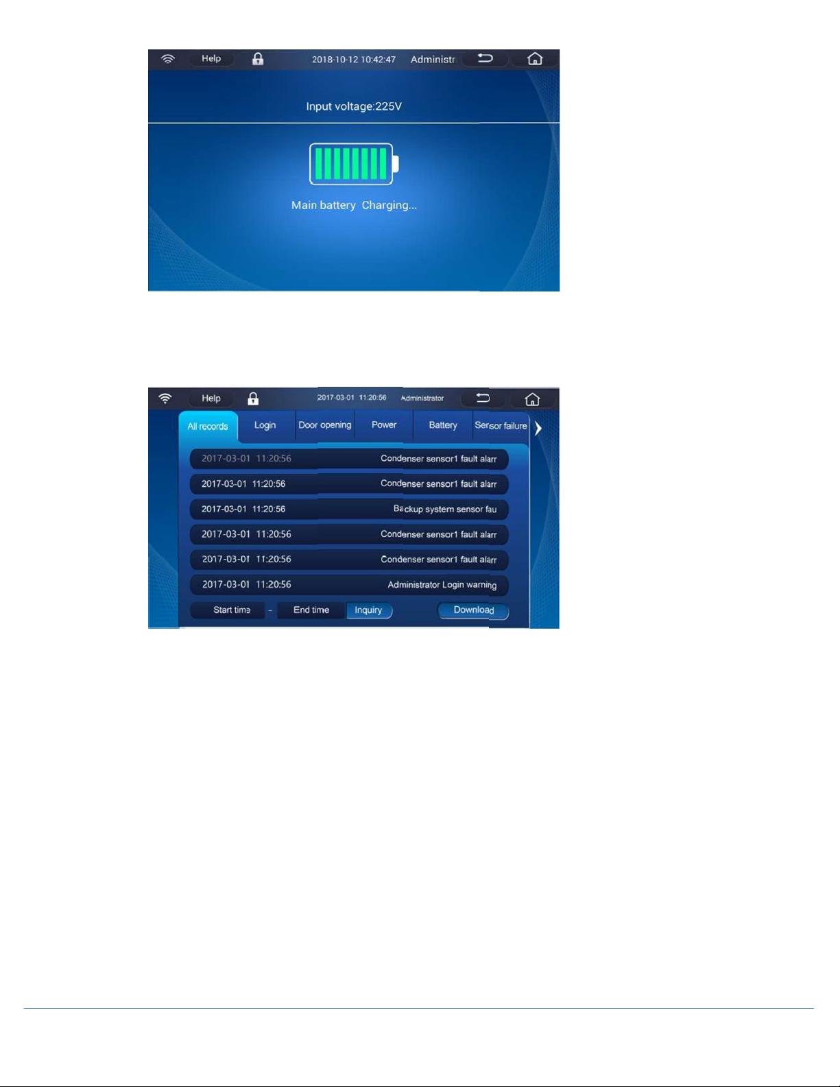
• [Alarm Record]:
Tap to query the All alarms, or check individual alarms: Logins, Door Alarm, Power Alarm, Battery Alarm,
Sensor Alarm, Temperature Alarm, Condenser Alarm, and Backup Alarm.
[Inquiry]: Input both the starting time and the ending time, and then tap [Inquiry] to view the
corresponding records in the desired interval.
[Download]: Input both the starting time and the ending time, and then [Download] to download the
corresponding records within this interval through USB.
• [Operating Status]:
Tap to query the freezer's real-time Internal Temperature, Set Temperature, High-/ Low- Temperature
Alarm Value, Ambient Temperature, Input Voltage, Cumulative Operation Time. The status of the
Compressor, Fan; as well as the data recorded by the electronic temperature recorder.
OM0299 PAGE 25 OF 41 REV 1 DECEMBER/2020
Page 26
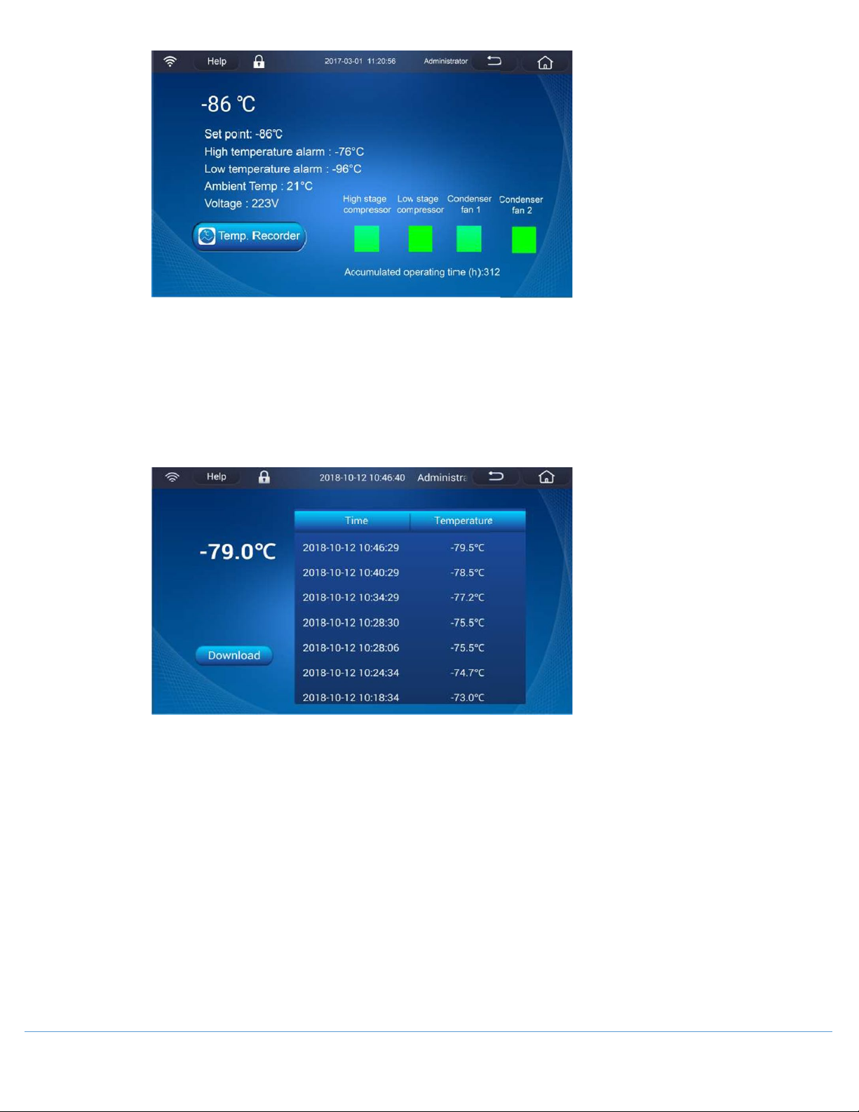
For the operation state of compressors and condenser fans; “Green” indicates that it is running and “Grey”
indicates that it is not running.
[Temp. Recorder]:
The electronic temperature recorder is used to collect the temperature inside the freezer. Tap [Temp.
Recorder] to view the recorded internal temperature. Tap [Download] to download the temperature data
via USB.
• [Backup System]:
Tap to view the Operating Status, Injection Status, Accumulated Injection Time, and Injection History. It
can set when connecting with backup system. If no backup system is present, the display will show in gray.
OM0299 PAGE 26 OF 41 REV 1 DECEMBER/2020
Page 27
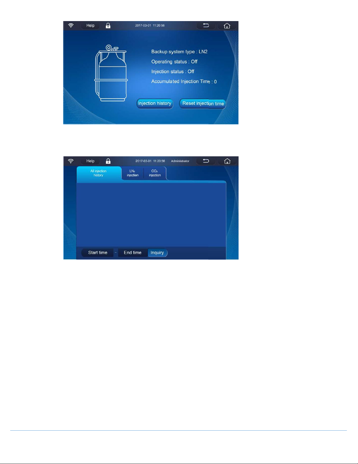
[Injection History]:
Displays the accumulated injection time since the last start-up.
[Inquiry]: Input both the starting time and the ending time, and then tap [Inquiry] to view the
corresponding records in the desired interval.
[Reset Injection Time]:
Clear some or all injection history.
• [Device Information]:
Tap to query and save the related information, electronic manual of the freezer, as well as upload/
download its configuration file and database information.
OM0299 PAGE 27 OF 41 REV 1 DECEMBER/2020
Page 28
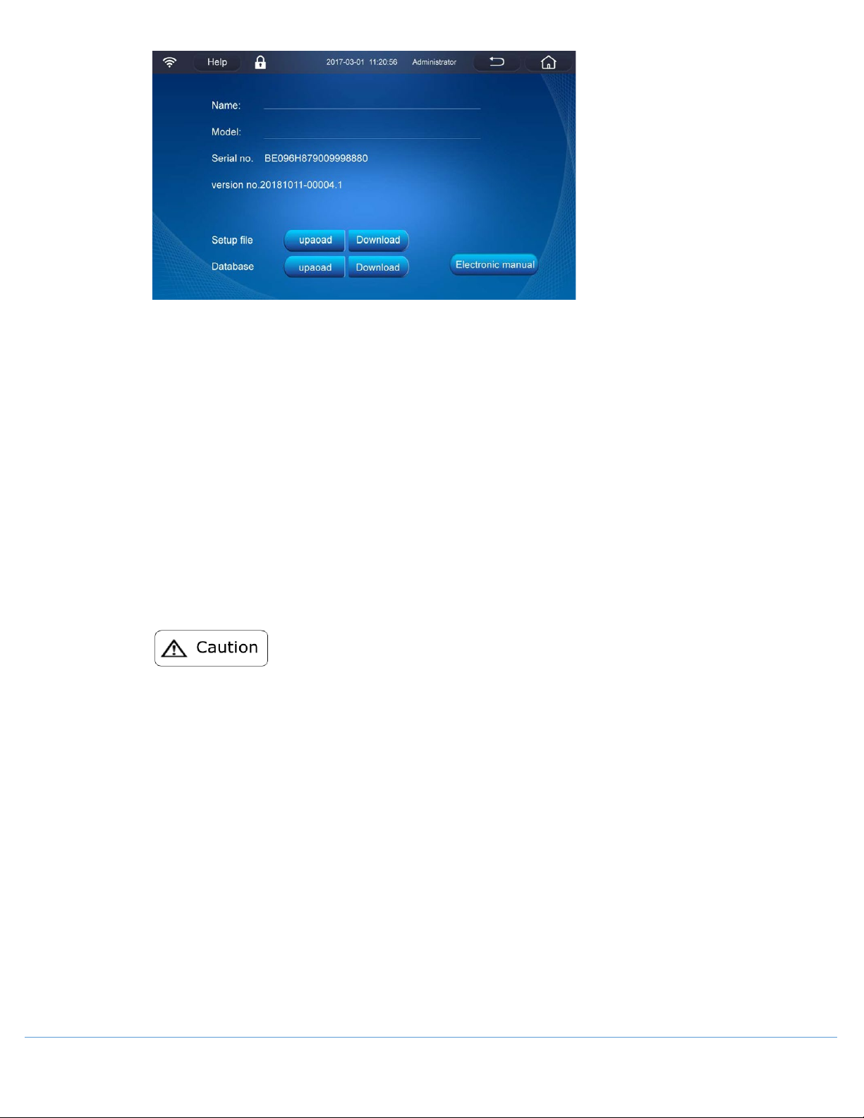
[Setup File]:
Tap [Download] to download the set parameters of this freezer to a USB disk in the established format via
USB, and then plug the USB disk that has saved the downloaded file to the USB interface of other freezers.
Tap [Upload] to upload a configuration file.
[Database]:
Tap [Download] to download the temperature data, alarm records, event records of this freezer to a USB
disk in the established format via USB, and then plug the USB disk that has saved the downloaded file to
the USB interface of other freezers.
Tap [Upload]” to upload this database to other freezers if desired.
[Electronic Manual]:
View the manual on the display screen.
o When exporting data to a USB, ensure USB disk is type FAT32.
o If the FAT32 USB disk cannot export data, please backup the file of the USB disk first and then
format the USB disk or try another brand FAT32 USB disk.
OM0299 PAGE 28 OF 41 REV 1 DECEMBER/2020
Page 29
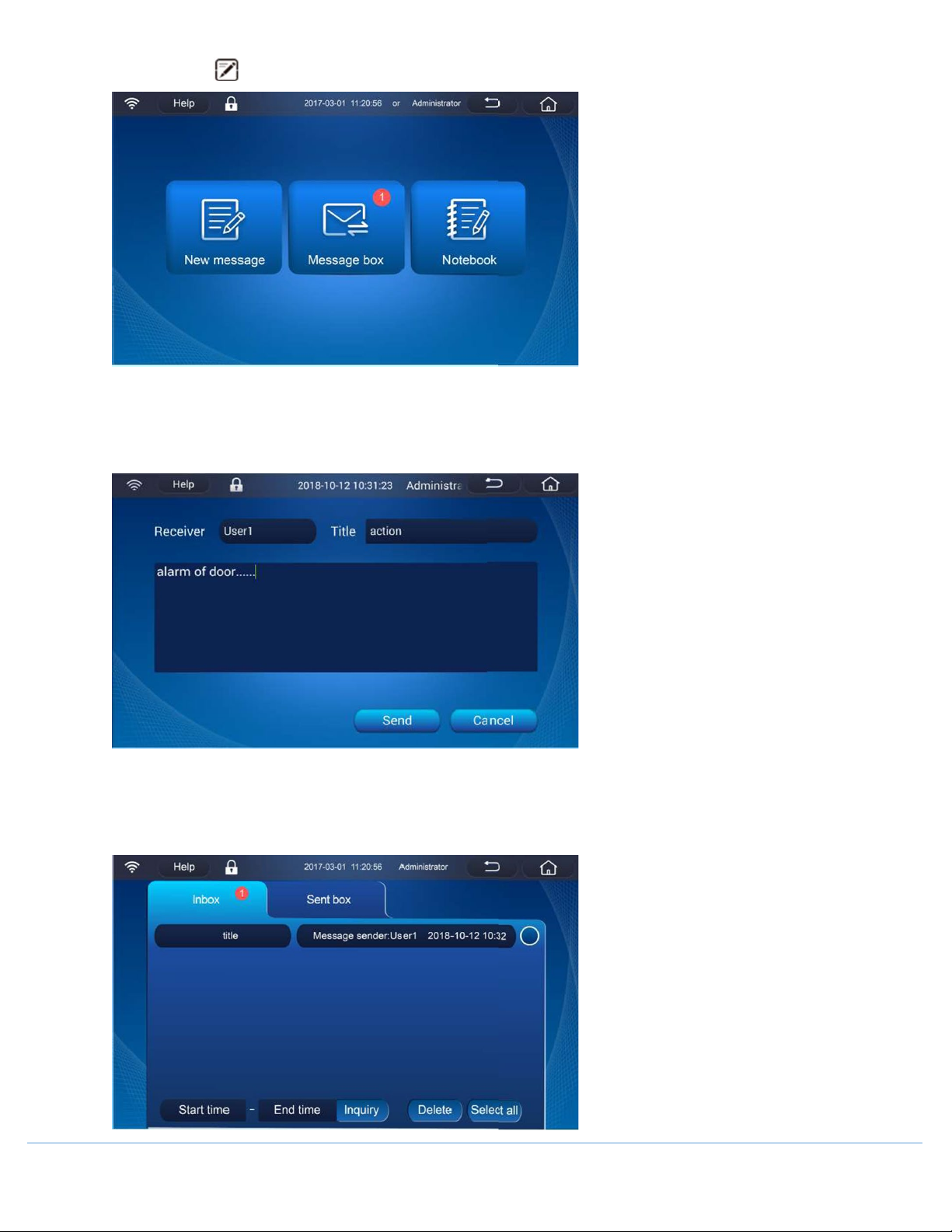
7.5 Message
[New Message]:
Create a message by tapping [New message]. Select the users the message will be sent to, enter a title in the title
bar, and enter the message content in the text box, then tap [Send].
[Message Box]:
Tap [Inbox] to view the messages that have been received. When a message has been read, the font will become
gray.
OM0299 PAGE 29 OF 41 REV 1 DECEMBER/2020
Page 30
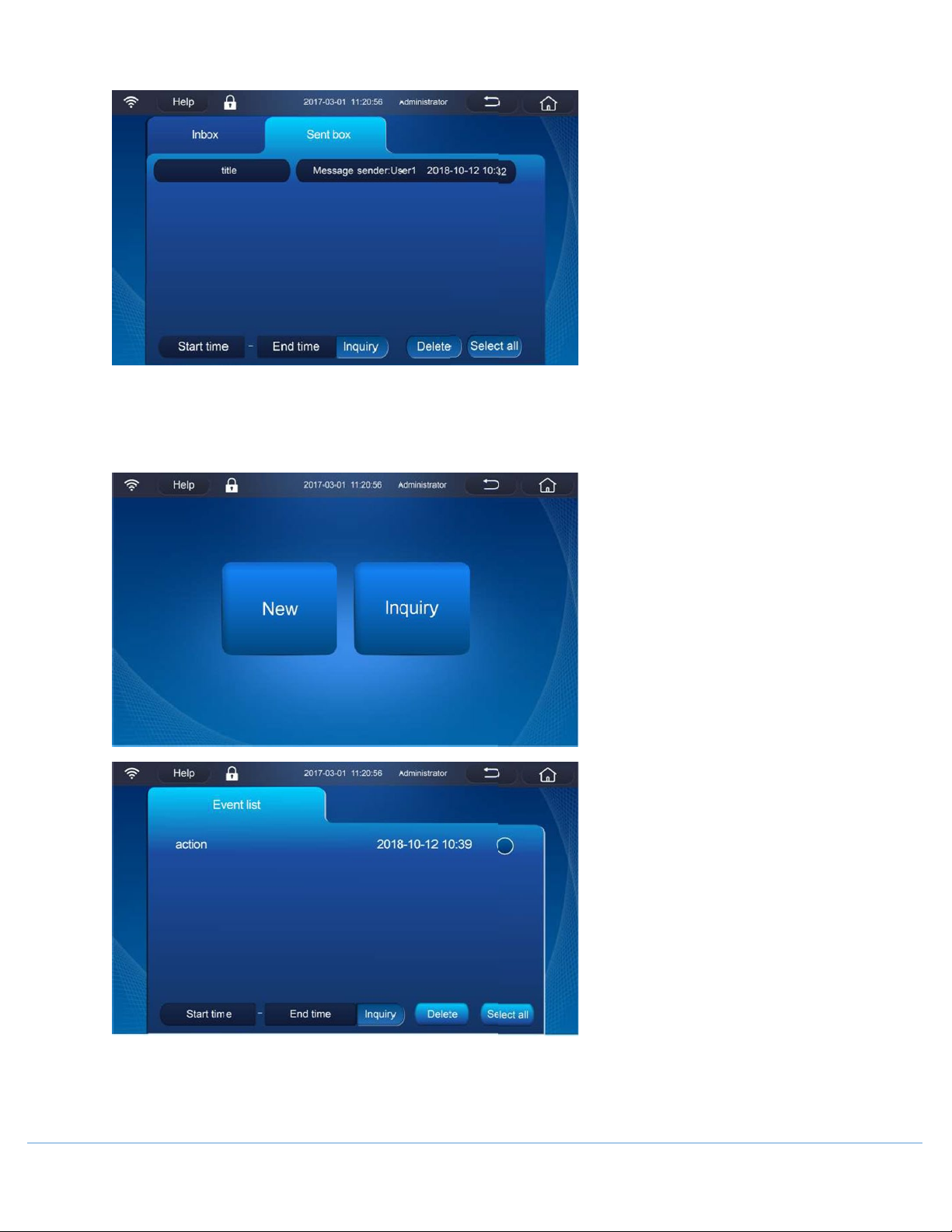
Tap [Sent Box] to view messages that have been sent.
[Notebook]:
Create new messages and view the records. For previous records, you can directly click them for modification and
saving in the pop-up interface; when clicking [Delete], you can delete one or all messages.
OM0299 PAGE 30 OF 41 REV 1 DECEMBER/2020
Page 31
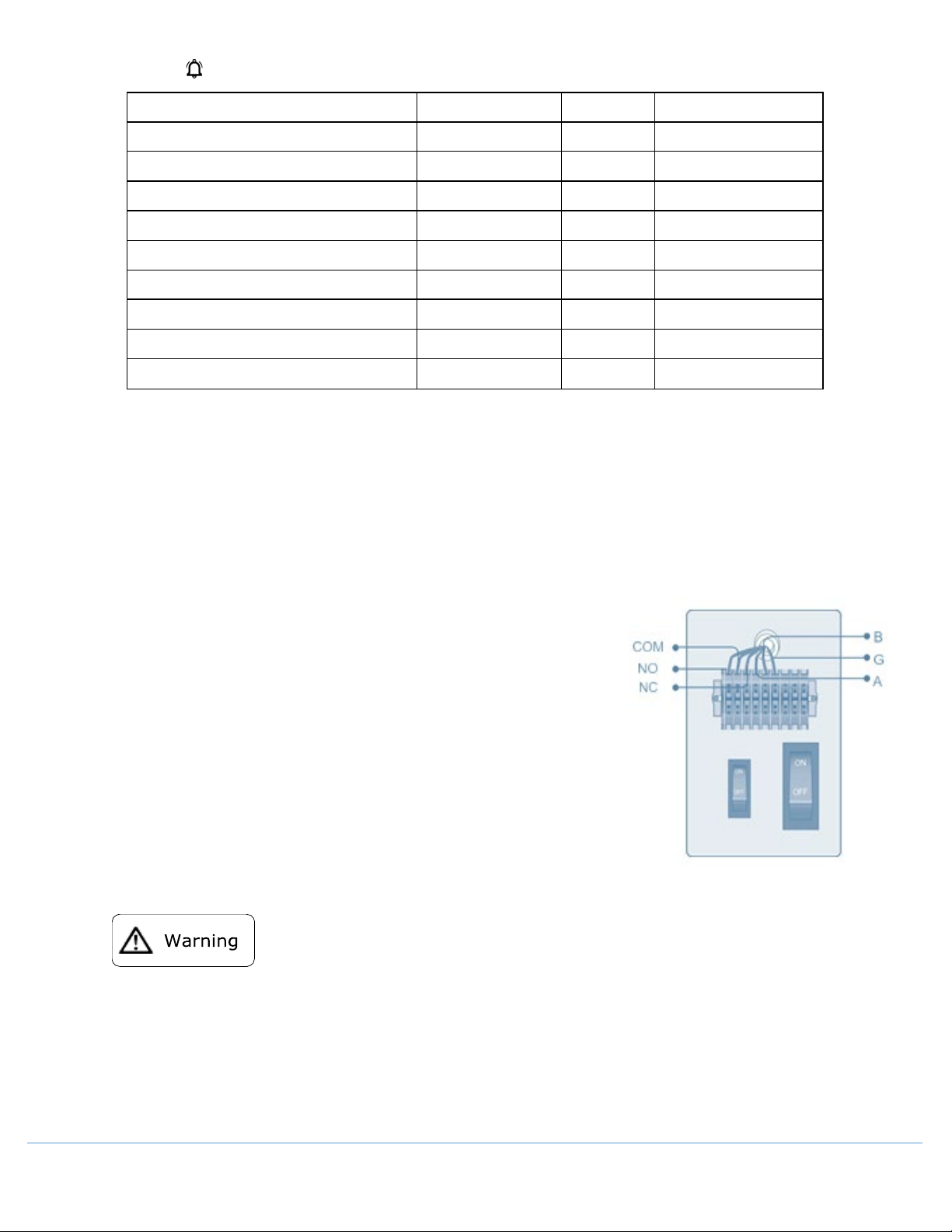
7.6 Alarm
Alarm Type
High-low temperature alarm
Power-off alarm
Door opening alarm
Main temperature sensor fault alarm Yellow
Heat exchanger fault alarm
Condenser dirty alarm
High ambient temperature alarm
Battery fault alarm
Backup system fault alarm
• Automatic Recovery of Alarm
o
Tap [×] on the upper right-hand corner in the prompt box to stop the buzzer alarm. If there
is no prompt box, click the alarm on the bottom of the homepage to view the alarm, and
then stop the buzzer alarm.
o
If the alarm condition is still active, the buzzer alarm will be recovered automatically 30
minutes after ceasing.
Tricolor lamp panel Buzzer
Red
Y Y
Red
Y Y
Red
Y Y
Yellow
Yellow
Yellow
Yellow
Yellow
Y N
Y N
Y N
Y N
Y N
Y N
Prompt box pops up?
•
Remote Alarm Terminal
o The remote alarm terminal is installed on the right side
of the freezer's engine cabin, and the alarm signal will be
output by this terminal. The load capacity of the terminal
is DC 30V, 2A.
o Contact output:
The remote alarm terminal is divided into: Normally
open, normally closed, common terminal.
Users may select normal open or normal close according
to their own requirements.
o Standard R485 port can be used to transmit freezer
temperature data to customer’s software for monitoring
8.0 Cleaning Maintenance
• T
o prevent electric shock or injury to operators, the AC power supply to the freezer must be
disconnected completely before any repair and maintenance work is to be performed.
During any repair maintenance work, do not inhale medical particles or aerosols near the equipment as
•
they might be harmful to your health.
OM0299 PAGE 31 OF 41 REV 1 DECEMBER/2020
Page 32
8.1 Cleaning the Freezer
• Clean the unit at least once a month.
• Use a dry cloth to wipe away loose dust inside and outside of the freezer. If the unit is dirty, use a clean cloth
soaked with a neutral detergent to clean the unit. Then use a dry cloth to wipe away any residual detergent
solution.
• Never pour water onto or into the unit. Doing so can damage the electric insulation and cause failure.
• Compressors and other mechanical parts are hermetically sealed, and they do not need lubrication. Users
should remove the frost on the chamber and clean the condenser filter as often as possible.
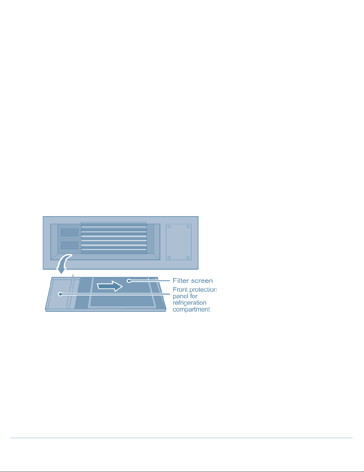
8.2 Cleaning the Condenser Filter
Clean the condenser filter when the control panel shows a signal for "Hot Condenser" and the alarm flashes. Even
if the light is not on, the condenser filter should be checked regularly according to the suggestion from the
distributor.
To clean the filter, follow the procedure below.
1. Pull off the front grill cover.
2. Pull out the filter screen.
3. Use water to wash the filter screen.
4. After the filter screen is dry, reinstall it back in its original position and close the cover.
5. If the “Hot Condenser” light is on before cleaning, check the light to make sure that it shuts off after cleaning.
If it does not shut off, please contact after-sales service personnel.
8.3 Defrosting
Frost and ice can form in between the door gasket and frame to form an air gap, which can decrease the
refrigeration effect of the unit. Please use the provided plastic scraper to defrost the interior doors.
1. To defrost, please refer to the instruction as follows:
2. Turn off any backup refrigeration system if there is one.
3. Remove the samples from the unit that needs to be defrosted. Move them to another unit or a container for
temporary storage.
4. Turn off the power supply.
5. Open the outer door and inner doors to let the unit thaw.
6. Use a dry doth to soak up and remove any water on the floor of the unit. Load the samples back into the unit
after it reaches the set temperature.
7. Turn on the backup refrigeration system if there is one.
OM0299 PAGE 32 OF 41 REV 1 DECEMBER/2020
Page 33
Do not use any sharp tools such as knives or screwdrivers to defrost.
8.4 Battery Maintenance
• When the control panel shows an alarm signal for “Low Battery”, check that the battery switch is turned on,
and the battery is charged. After one week of charging, recheck the battery capacity. If normal, the battery
should be in full capacity. If the capacity is still low, continue changing the battery. If the battery is not
charging, contact Nuaire.
• The battery that supports the power outage alarm is a consumable item. The life expectancy for the lithium
battery is 5 years (Lead-acid battery is 2-3 years). If the battery is more than 5 years old (Lead-acid battery 23 years), the battery should be replaced because the alarm function may not work properly. Contact Nuaire
for assistance.
8.5 Disposal of Freezer
• If the unit is to be stored unused in an unsupervised area for an extended period, ensure that the doors are
locked completely with a key.
• The disposal of the unit should be accomplished by appropriate personnel. Remove doors to prevent
accidental injury.
8.6 Disposal of Battery
This freezer is equipped with a rechargeable battery. This battery is recyclable. When the battery reaches the end
of its life, please contact a local recycling organization for inspection or properly discard the battery.
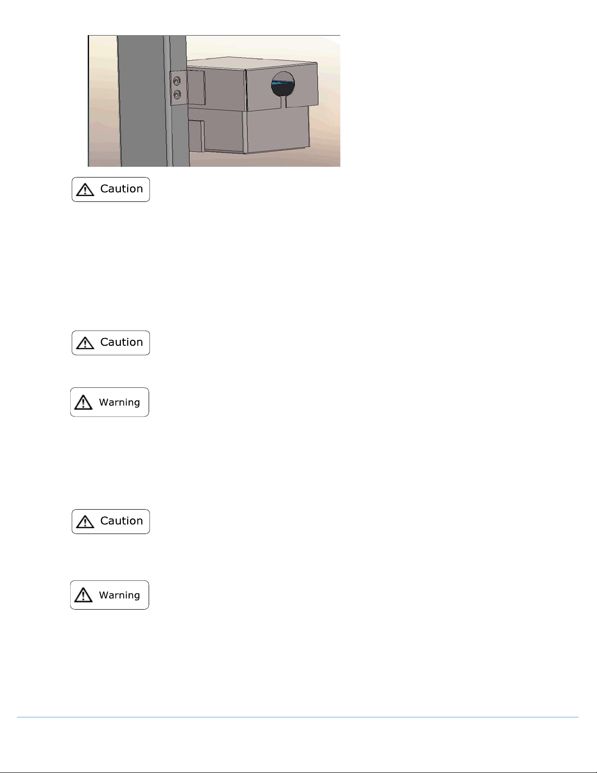
1. Location of the battery.
The battery in the electric cabinet is for the power outage alarm. It is located inside the control box of the
right side of the unit.
To prevent electrical shock, only a qualified technician should replace the battery.
Removal of the battery
2.
Turn off the power of the unit and unplug the power cord from the socket.
•
Use a screwdriver to remove the screws on the side panel and take down the side panel.
•
Unplug the connecting terminals from the battery.
•
Remove the bracket that holds the battery in place. Remove the battery.
•
Follow regulations to recycle the battery or discard it properly.
•
When changing the battery, you must make sure that the brown wire connects to the positive pole of the
battery, and the blue wire connects to the negative pole of the battery. The polarity must not be reversed.
Incorrect polarity can damage the main control board and it will not charge the battery.
OM0299 PAGE 33 OF 41 REV 1 DECEMBER/2020
Page 34
After interruption of power supply, the battery can maintain the standby time of the touch screen for ~22 hours.
9.0 Optional Accessories
9.1 Temperature Recorder
When using the temperature recorder, please refer to the “User manual for Temperature Recorder” provided
with the recorder.
The temperature recorder should only be installed by professionals or Nuaire approved Service Provider.
Before installing the temperature recorder, please cut off the power supply to avoid electric shock or fire.
9.2 LCO2 Backup Cooling System
For installation and operation of the backup cooling system, please refer to the user's manual provided with the
system.
For LCO2 back up system, please make sure the LCO2 supply bottle has an internal liquid dip tube to make sure
the liquid is fed to the backup system. For LN2 backup system, please use a LN2 Dewar of 35 to 50 psig.
• Whenever a CO2 or LN2 backup system is installed, the location of the freezer must be well ventilated.
Increased concentration of CO2 in the air is harmful and even fatal. If the ventilation is poor, alternative
methods should be considered to reduce the nitrogen or CO2 concentration to the normal level.
• If a LCO2 or a LN2 cylinder fell to the ground, its valves may get damaged, resulting in a risky condition.
Fastening the bottles with a chain are to secure them to ensure the bottles are positioned vertically and
securely.
OM0299 PAGE 34 OF 41 REV 1 DECEMBER/2020
Page 35
• The temperature of liquid CO2 /LN2 is extremely low, which could cause frostbite. When replacing the
cylinder, please always wear a pair of protective glasses and protective clothes.
• This kind of backup cooling system should be used with the LCD panel.
9.4 Electromagnetic Lock
The electromagnetic lock can effectively enhance the safety of specimen access inside the freezer, which is
convenient for use. When using it, make sure to swipe the card or use the fingerprint to unlock the lock before
opening the door. If not swipe the card or use the fingerprint, or pull the handle forcibly, it may destroy the
electromagnetic lock.
Usage method:
• Before using the electromagnetic lock for the first time after unpacking, firstly open the door, and then remove
the small clip for fixing the spring of electromagnetic lock.
• When the electromagnetic lock is unlocked, it may continuously maintain the open state for about 10 seconds.
If more than 10 seconds later, you need to open the door once again, please swipe the card or punch the
fingerprint. The unlocked/ locked state of electromagnetic lock is displayed on the touch screen.
• If the freezer operates in normal mode, any attached magnetic card can be used to open the door by swiping
it in the card reading area of the display panel cover, but the fingerprint does not have the function.
• If the freezer operates in authorized mode, first ensure that the magnetic card or fingerprint is registered on
it. When you can create a new account, the registration will be completed by swiping the card or punching
the fingerprint, meanwhile a magnetic card shall be assigned to the new account. Only when the magnetic
card corresponds to the login account, can the electromagnetic lock be unlocked.
• If the user does not use the electromagnetic lock temporarily, it can be fixed with a clip, to ensure that the
door can be opened / closed without swiping the card or using the fingerprint.
• When there is a loss of power or the backup battery power is out of power, please contact technical support
personnel should there be a need to open the freezer door.
• If the card is not swiped or fingerprint information is not entered, the door should not be opened forcibly as
it can damage the electromagnetic lock.
OM0299 PAGE 35 OF 41 REV 1 DECEMBER/2020
Page 36
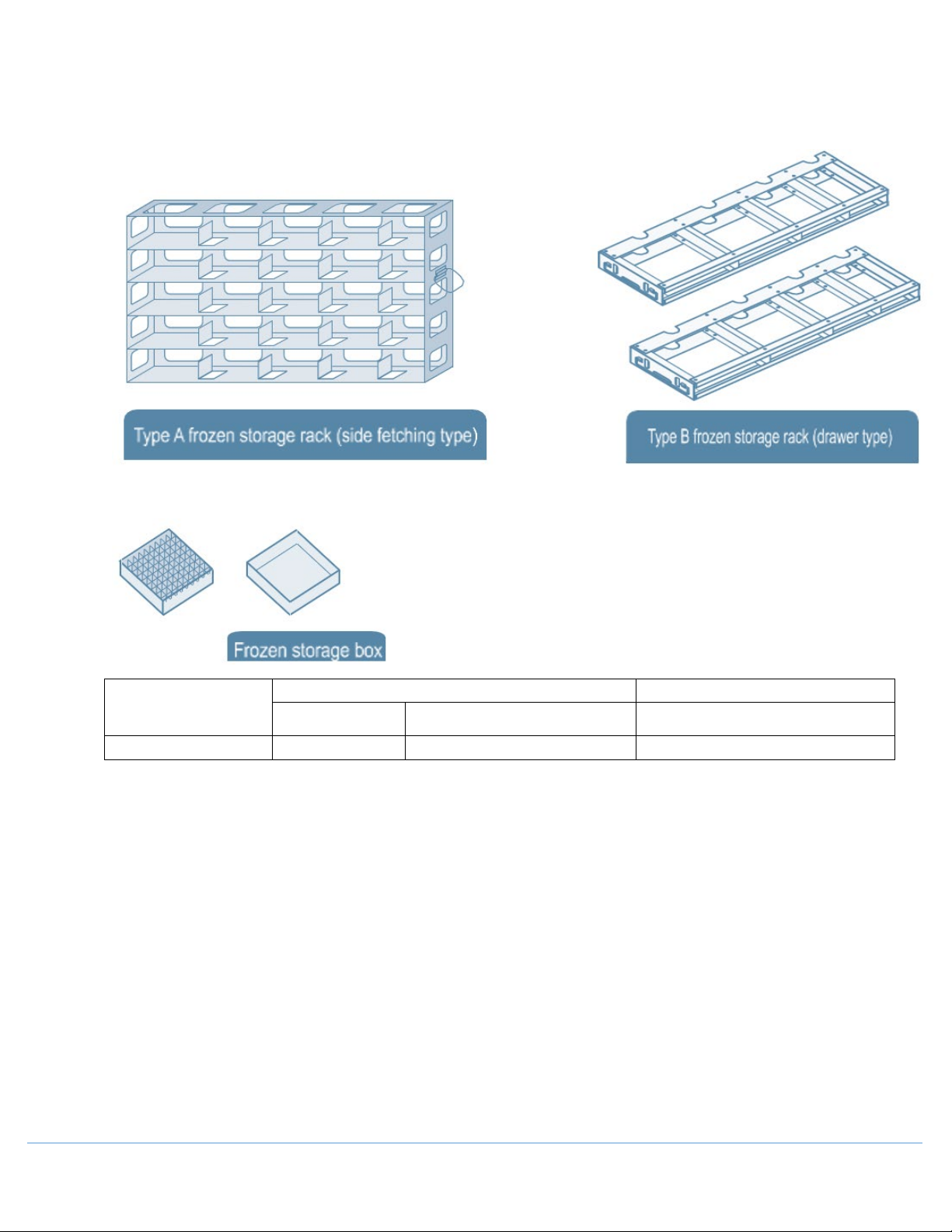
9.5 Frozen Storage Racks and Storage Boxes
Storage Rack (Type A/B are available)
Storage Box
NU-99729VFT
5×5
20
500
When the freezer stores small sizes of materials, the frozen storage rack and the frozen storage box can be used
to utilize the space more effectively.
Model
Variety Amount Amount
OM0299 PAGE 36 OF 41 REV 1 DECEMBER/2020
Page 37
10.0 Troubleshooting
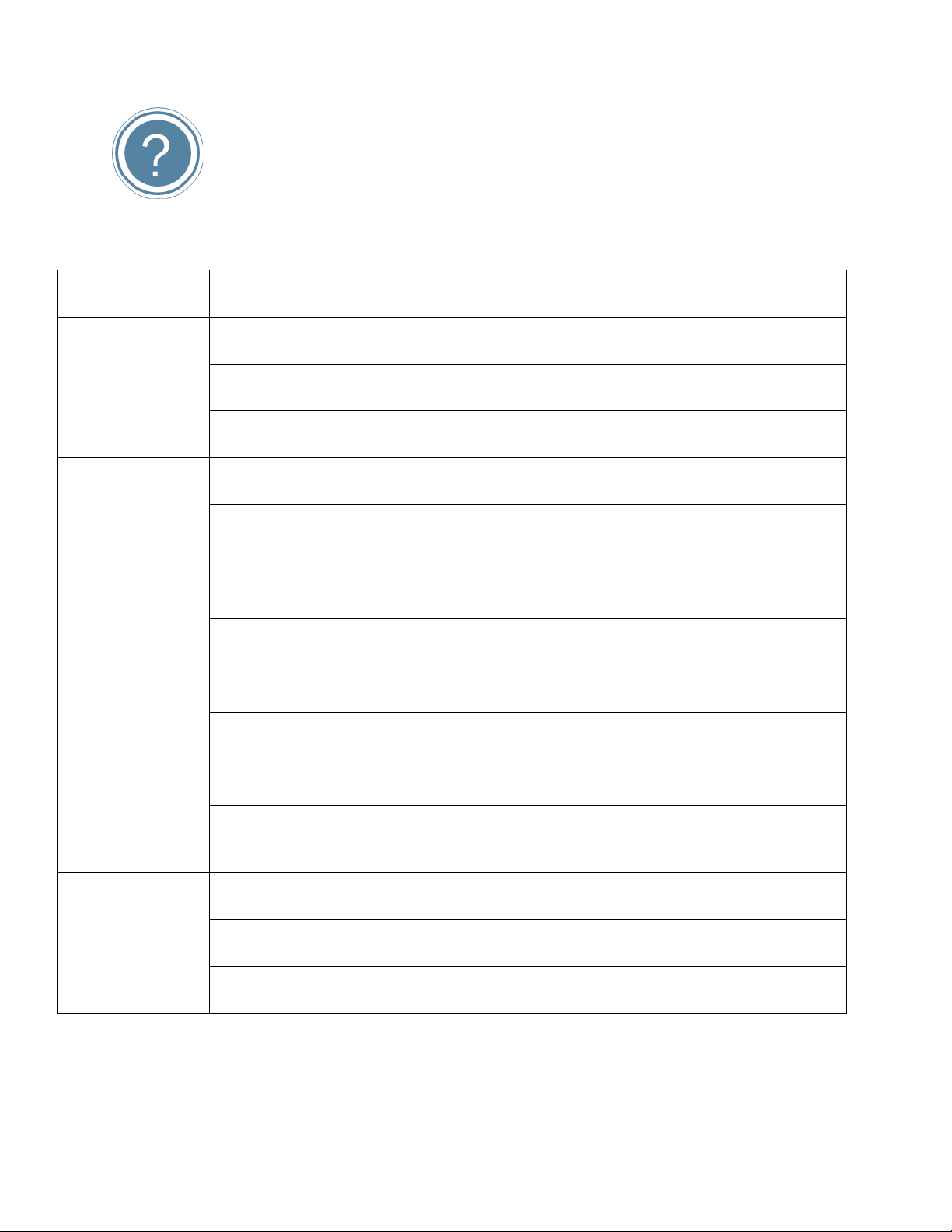
Should there be any malfunctions in the system, please attempt to answer the following questions before
notifying maintenance or calling Nuaire. Please do not dismantle the freezer yourself.
Fault
Freezer does not
start up
refrigeration
Poor
effect
Troubleshooting
Is the power supply normal? Has the main protector been turned on yet?
Is the voltage supply too low?
Is there any voltage input from the outside?
Is the ambient temperature too high?
Are the inner doors and outer doors closed properly? (Has any ice or frost damaged the
seals between the door and the frame?)
Is the condenser filter clogged?
Is the temperature setting correct?
Is the freezer being kept away from direct exposure to sunlight?
Is the freezer near any heat source?
The unit is noisy
Is the porthole plug installed in the porthole with proper insulation materials?
Has the freezer been loaded with too many non-frozen samples within the last few
hours?
Is the unit set on a firm and level floor?
Is the exterior of the unit touching any objects?
Is the freezer unit leveled with the leveling legs?
OM0299 PAGE 37 OF 41 REV 1 DECEMBER/2020
Page 38
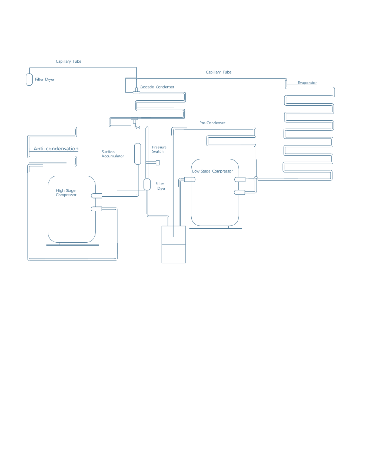
11.0 Refrigeration and Wiring Diagram
11.1 Refrigeration Diagram
OM0299 PAGE 38 OF 41 REV 1 DECEMBER/2020
Page 39
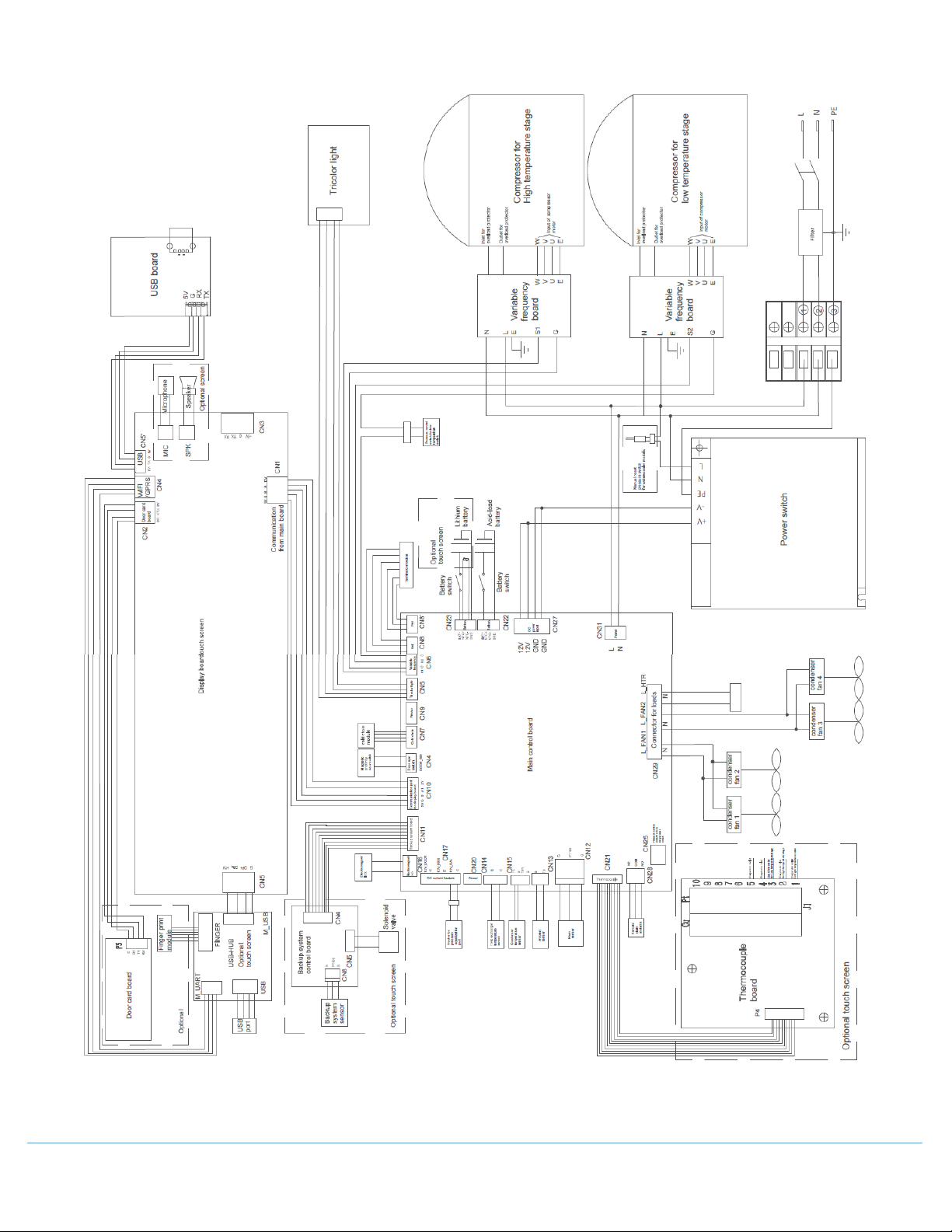
11.2 Wiring Diagram
OM0299 PAGE 39 OF 41 REV 1 DECEMBER/2020
Page 40
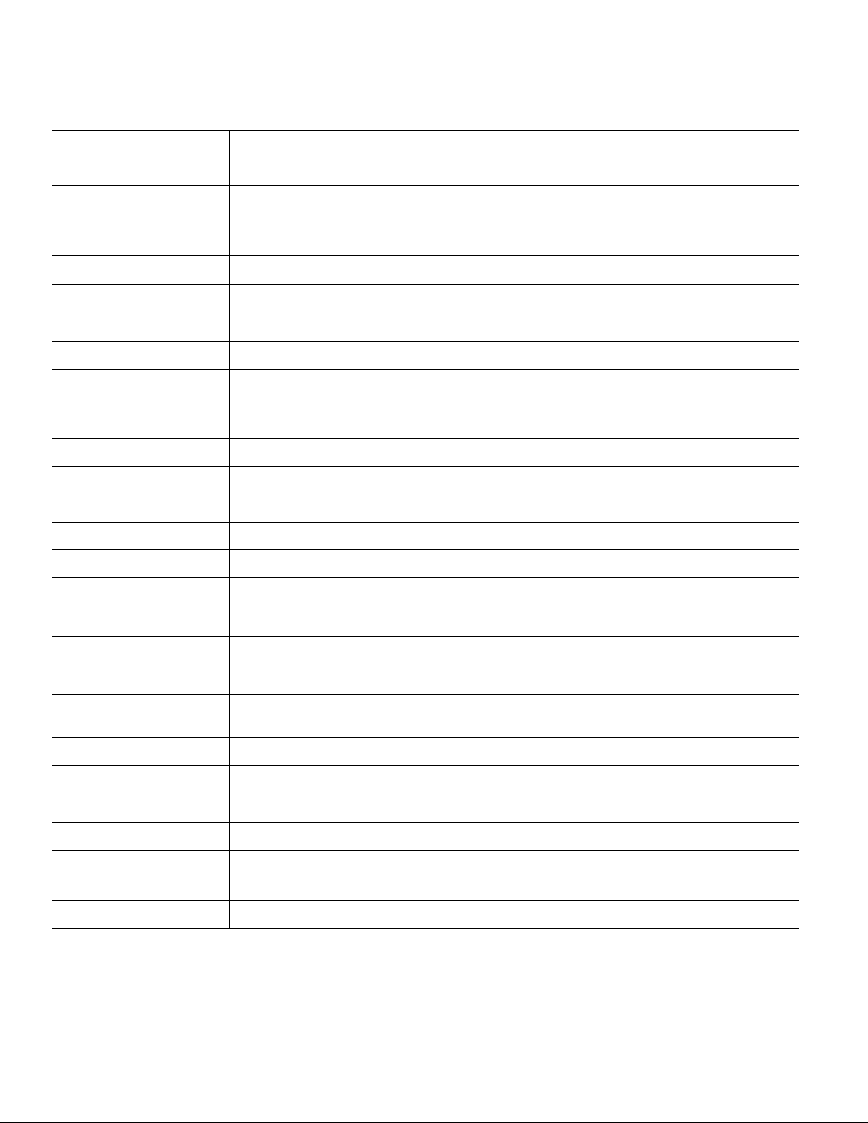
12.0 Specifications and Technical Data
Exterior/Interior Wall
Electric Shock Protection
Type
Pollution Degree
2
12.1 Specification Table
Name Ultra-Low Temperature Freezer
Model NU-99729VFT
Material
Outer Doors Coated cold rolled steel
Inner Doors Plastic framed PS board
Shelves Stainless shelves (height adjustable)
Porthole for Testing 2
Insulation Vacuum insulated with polyurethane foam (non-CFC)
Compressors High stage: hermetically sealed Low stage: hermetically sealed
Evaporator Copper tube
Condenser Finned coil
Refrigerant R170 R290
Temperature Controller Microprocessor controller
Temperature Display LCD display
Temperature Sensor RTD (Pt100)
Alarm Device
High/Low temperature alarm, probe failure alarm, Hot condenser alarm, Ambient
temperature alarm, Low battery alarm, Door ajar alarm, Power failure alarm
Coated cold rolled steel
Battery of Remote Alarm
Terminals
Ambient Temperature 10 to 32 °C
Freezer Temperature -40 to -86 °C
Foaming Cabinet HFO-1233zde
USB Standard
Rs485 Standard
Overvoltage Category II
Rechargeable battery: 12 VDC, charges automatically Lithium battery
Maximum load:3 0VDC, 2A
I
OM0299 PAGE 40 OF 41 REV 1 DECEMBER/2020
Page 41
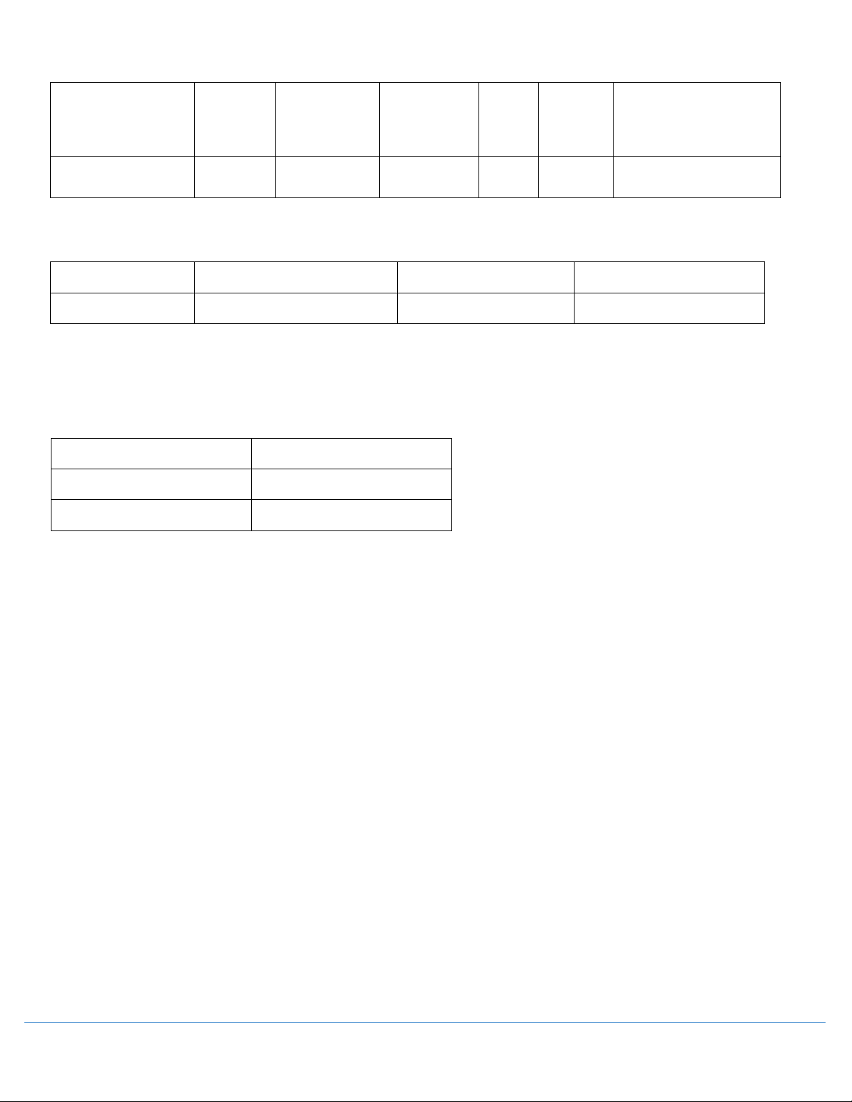
12.2 Technical Data
Net Volume
41.2” x 38.9” x 78.0”
Model
NU-99729VFT 729 100-230~ 50/60 1100 350
(L)
Rated Voltage
(VAC)
Rated
Frequency (Hz)
Rated
Power
(W)
Weight (kg)
12.3 Global Warming Potential
Model Rated voltage (VAC) Rated frequency (Hz) CO2 equivalent (Tonnes)
NU-99729VFT 100-230~ 50/60 0.005
This product contains fluorinated greenhouse gases covered by the Kyoto Protocol. Do not vent into the
atmosphere.
GWP=global warming potential
Refrigerant type GWP
R170 20
Dimensions (W×D×H)
Inches [mm]
[1046 × 998 × 1980]
R290 20
OM0299 PAGE 41 OF 41 REV 1 DECEMBER/2020
 Loading...