

Page 1

OM0088 Page 1 of 38
FumeGard Polypropylene Fume hoods
Models NU-162/164/E
Bench Top
Operation & Maintenance Manual
April, 2021
Revision 13
230VAC Only
Manufactured By:
NuAire, Inc.
2100 Fernbrook Lane
Plymouth, MN 55447
Toll-Free: 1-800-328-3352
In Minnesota: (763)-553-1270
Fax: (763)-553-0459
Page 2

OM0088 Page 2 of 38
April/2021
About This Operation and Maintenance Manual
The information contained in this manual is intended to reflect our current production, standard configuration
models, along with the more frequently purchased options. Because this product is designed to conform to a
wide variety of unique customer requirements/options/equipment, any modifications, additions and/or shop
drawings are appended in the back flap of this manual, as well as any product test procedures/performance test
procedures that may impact the performance of this product according to established test procedures (i.e.
SEFA-5th Edition Desk Reference, ASHRAE 110-2016, etc.) for fume hoods. All fume hoods are factory tested to
SEFA-5th Edition Desk Reference under controlled (ideal) laboratory environmental conditions, and a copy of the
original factory test report is also appended to this manual. In case this manual and/or test report is lost or
misplaced, NuAire, Inc. retains a copy in our files. A replacement copy can be obtained by calling or writing to
NuAire, Inc. stating the model number, job location or serial number and a brief description of the information
desired. NuAire, Inc. reserves the right to alter/modify our standard configuration production model in order to
provide you, our valued customer, and the best possible fume hood.
Page 3

OM0088 Page 3 of 38
April/2021
FumeGard Polypropylene Fume hoods
Models NU-162/164/E
Bench Top
Operation and Maintenance Manual
Table of Contents
Section No. 1.0 ................................................... General Information
Section No. 2.0 ................................................... Models & Types
Section No. 3.0 ................................................... Construction Features
Section No. 4.0…………………………………………………Warranty
Section No. 5.0 ................................................... Shipments
Section No. 6.0 ................................................... Installation Instructions
Section no. 7.0………………………………………………...General Maintenance
Section No. 8.0 ................................................... Electrical/Environmental Requirements
Section No. 9.0 ................................................... Selection of Hood Face Velocity
Section No. 10.0 ................................................. Perchloric Acid Hoods
Section No. 11.0………………………………………………Disposal & Recycle
Section No. 12.0………………………………………………Polypropylene
Drawings
BCD-05783 ......................................... NU-162 Bench Top Fume hood
BCD-05970 ......................................... NU-162 Bench Top (28” Window Access)
BCD-05784 ......................................... NU-164 Bench Top Fume hood
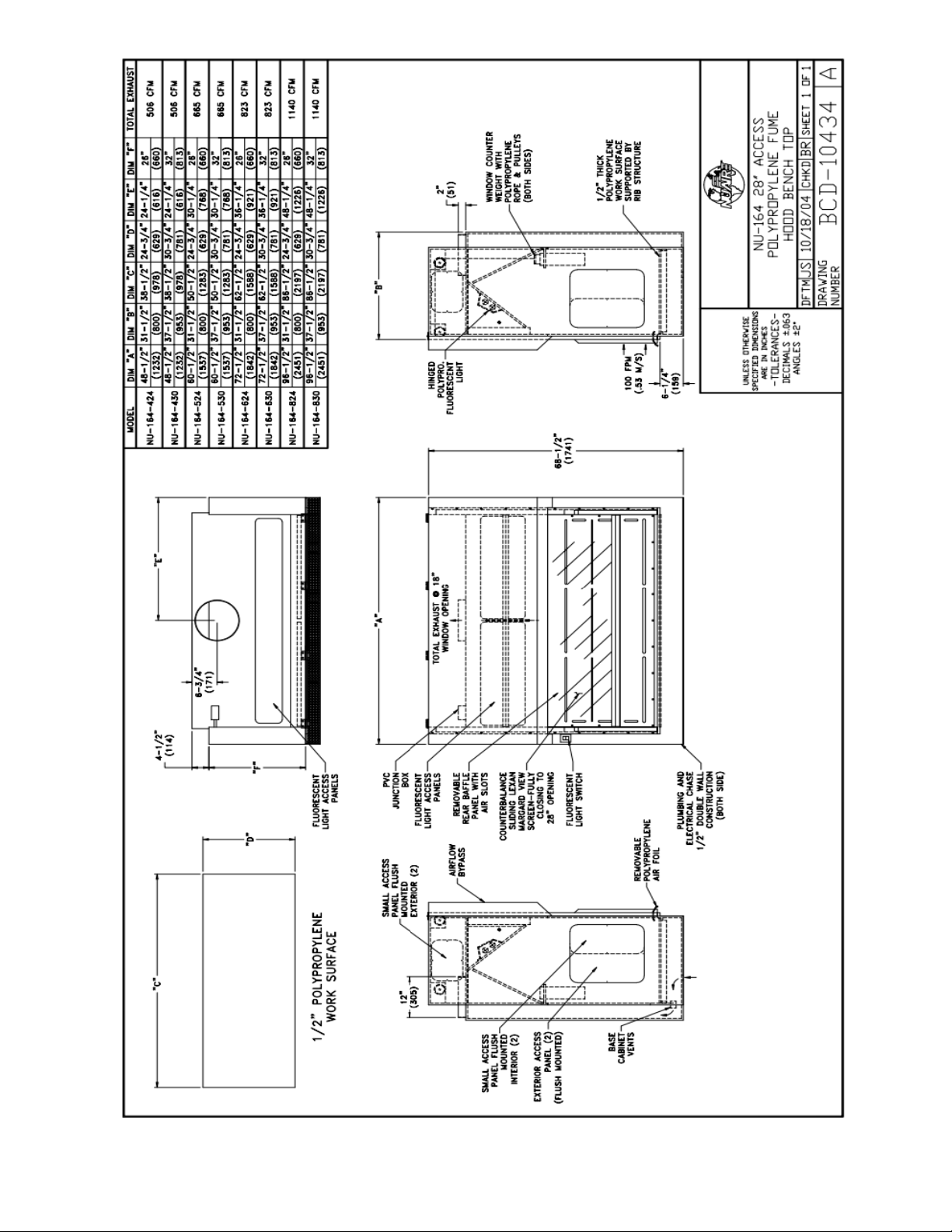
BCD-10434 ......................................... NU-164 Bench Top (28” Window Access)
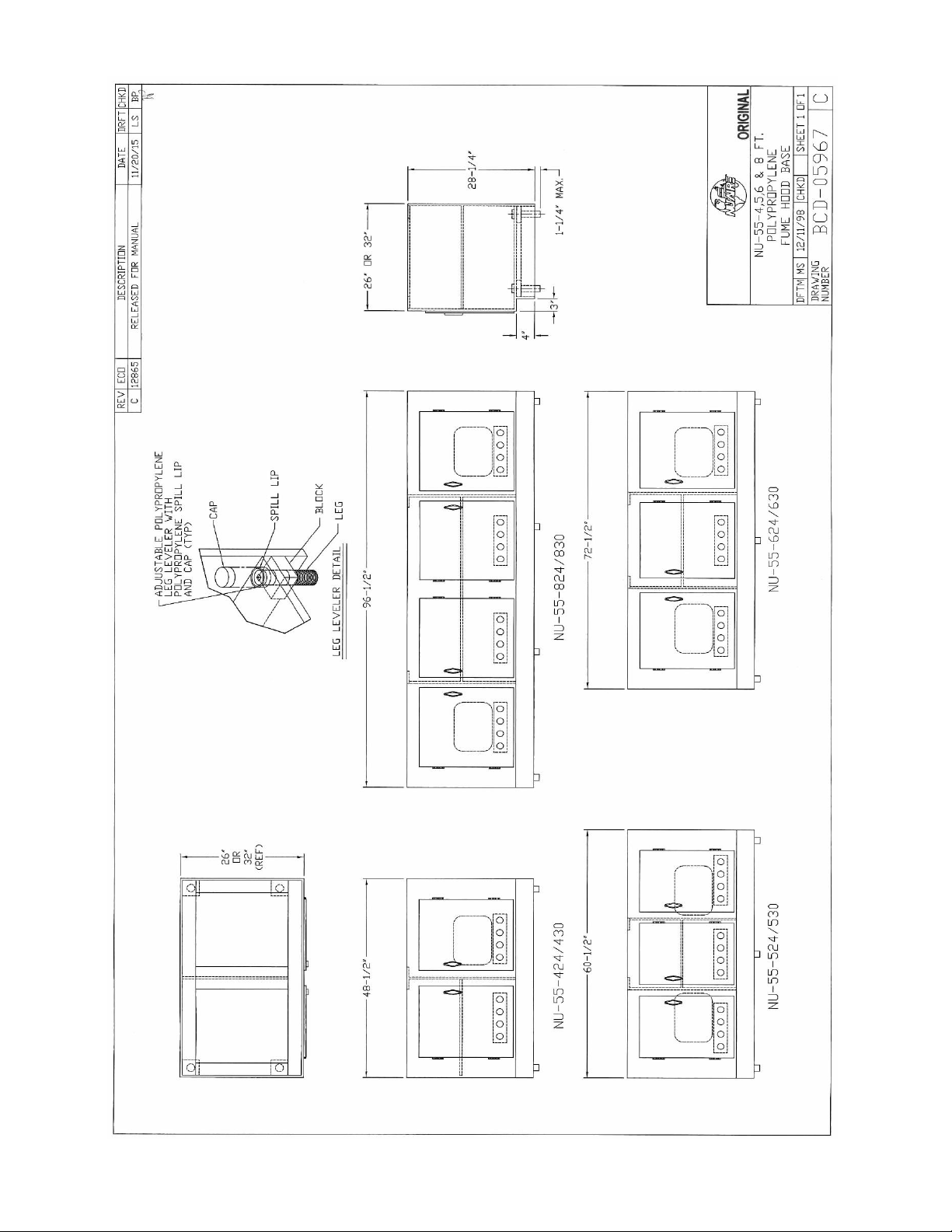
BCD-05967 ......................................... NU-55 Polypropylene Bases
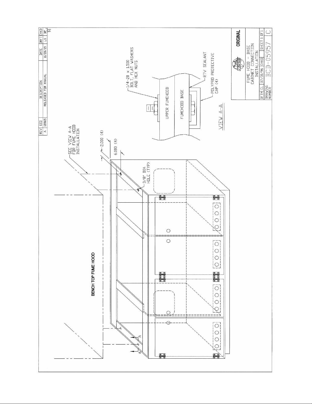
BCD-05957 ......................................... Fume hood/Base Cabinet Installation
BCD-05780 ......................................... Closure Panel/Seismic Installation
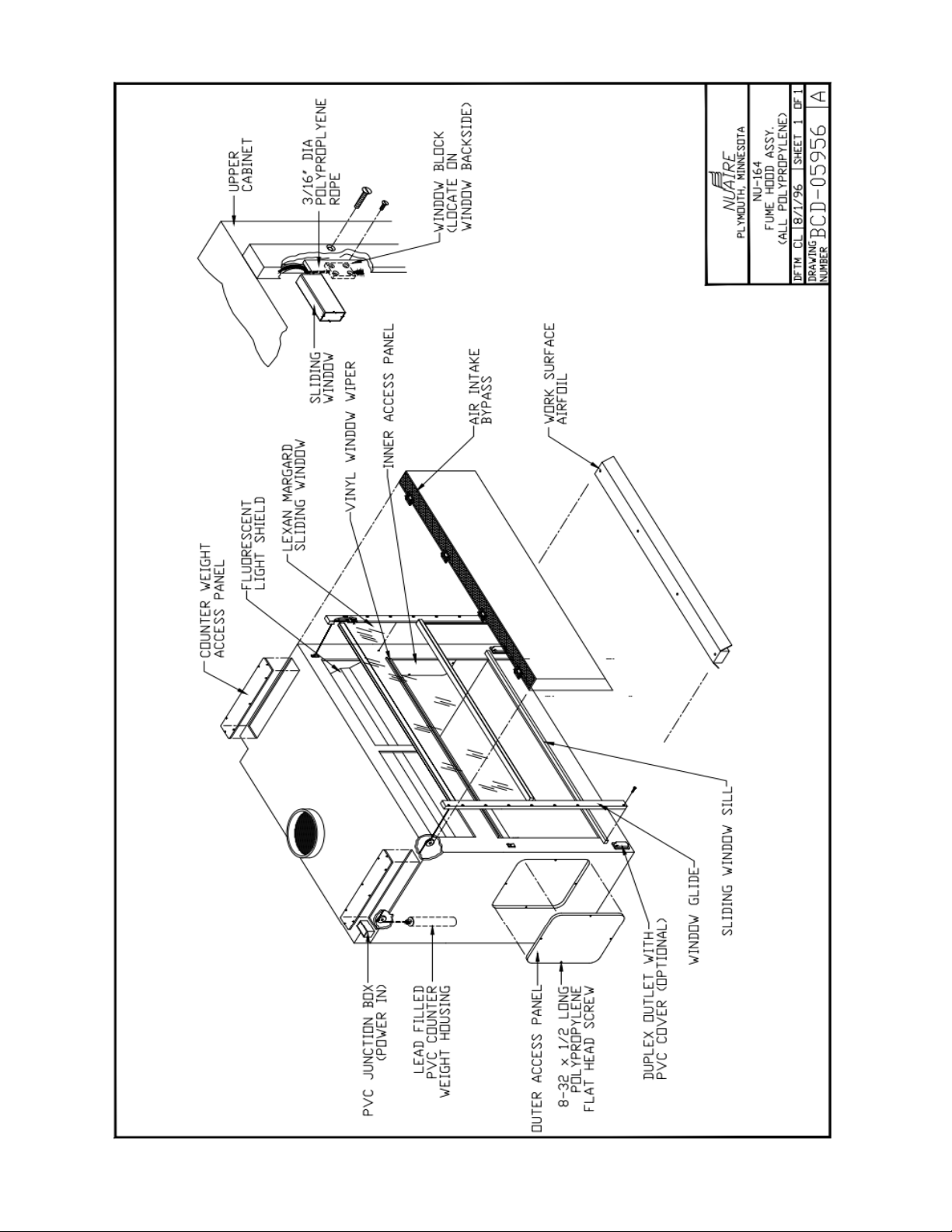
BCD-05956 ......................................... NU-164 Exploded Drawing
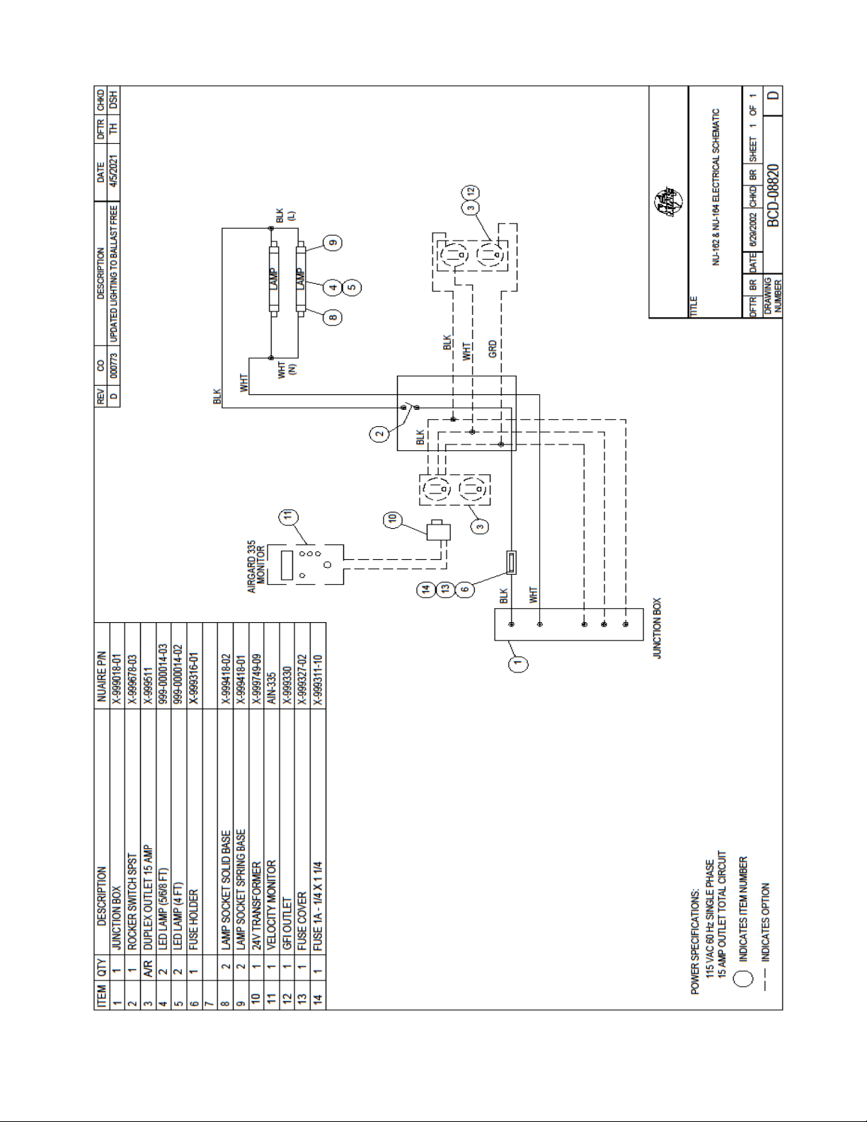
BCD-08820 ......................................... NU-162/164 Electrical Schematic
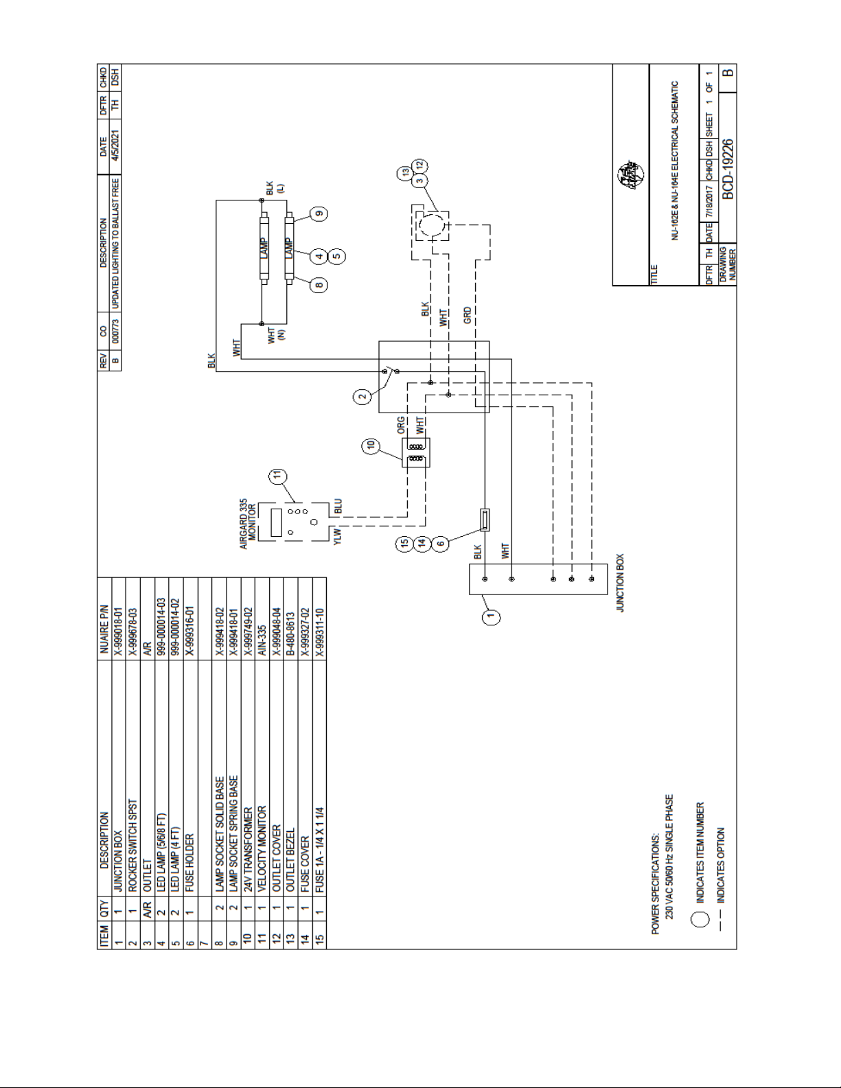
BCD-19226 ......................................... NU-162E/164E Electrical Schematic
Page 4

OM0088 Page 4 of 38
April/2021
FumeGard Polypropylene Fume hoods
Models NU-162/164/E
Manufactured By:
NuAire, Inc. - Plymouth, Minnesota
1.0 General Information
1.1 Description
A laboratory fume hood is defined to be a ventilated enclosure designed to capture, contain, and exhaust
fumes, gases, vapors, mists, aerosols, and to a lesser extent, particulate matter generated within the
hood interior. The enclosure generally consists of rear, side, and top panels with an open face, typically
provided with a means to adjust the face opening via a vertical or horizontal sliding sash.
The capture effectiveness of a laboratory fume hood not only depends on a properly designed and
balanced hood, but also on the laboratory environment in which the hood is expected to perform. This
includes the exhaust system (ducting and blower); make up (supply) air distribution within the
laboratory, and the intended application or procedure to be used in the hoods. Careful selection and
coordination of the above components will provide a safe and functional fume removal system.
Fume hoods can be constructed from a wide variety of materials; painted cold-rolled steel, fiberglass,
specially coated cold-rolled steel, stainless steel, acrylic, PVC and/or thermoplastics. The selection of
hood construction material is totally dependent on the intended application. All NuAire fume hoods are
constructed from stress relieved white polypropylene, 100 percent metal free, and intended for use in
high acid environments, in the fields of trace metal analysis, materials analysis, toxicology,
semi-conductor development, prototype/production and/or etching/plating operations. Polypropylene’s
excellent overall solvent/acid resistance makes this fume hood an excellent choice for long lasting, highly
corrosive resistant, metal free applications.
1.2 Fume hood Types
1.2.1 Conventional Hoods
An enclosure without an airfoil directional vane across the bottom of the access opening and
without a bypass, as the sash is lowered; the face velocity increases rapidly and may become
objectionably high as the sash is closed. With the sash completely closed, airflow through the
hood is insufficient to carry vapors away. Conventional hoods are potentially subject to interior
rolling or turbulence caused by, for the most part, the increased face velocities as the sash is
lowered. This may bring fumes from the hood interior out to the hood face, where room air
currents and/or laboratory personnel may cause fumes to escape the hood face.
Page 5

OM0088 Page 5 of 38
April/2021
1.2.2 Bypass Air Hood
A conventional hood that has a bypass, protected by a grill, which maintains a relatively constant
volume of airflow through the hood and as the sash is closed, air is bypassed at the top of the
hood, causing the hood face velocity to increase much less rapidly than a conventional hood.
A deflector vane or airfoil across the bottom of the hood face opening that directs airflow across
the work surface is usually provided. The deflector vane provides a permanent opening even
when the sash is closed, exhausting the majority of air through the bypass.
1.2.3 Auxiliary Air Hood
An Auxiliary Air Hood is the same as a bypass air hood with the addition of an auxiliary air bonnet
on top of the hood that provides a direct source of make-up air (i.e. an “air-wash” directed down
toward hood face opening), in addition to the make-up air provided to the laboratory. Auxiliary
air hoods purport to improve capture effectiveness of laboratory hoods as well as save
conditioned air. Present experience, however, has shown that these claims may have dubious
value in that: (1) the auxiliary air must be tempered for operator/laboratory comfort, (2) the
cost of providing a separate auxiliary air supply may have negligible payback, and (3) the
improved capture effectiveness of the hood has not been demonstrated with existing test
procedures.
1.2.4 Special Purpose Hoods
1.2.4.1 Radioisotope Hoods
Radioisotope Hoods are designed primarily for use with radioactive chemicals and
require special treatment. These hoods must be designed for cleanability, typically
requiring all-welded stainless steel interiors as well as exhaust air treatment such as
HEPA/charcoal filtration. Polypropylene is unsuitable as a construction material.
1.2.4.2 Perchloric Acid Hoods
Hoods for use with perchloric acid require very special treatment. Perchloric acid will
form explosive salts particularly if in contact with organic chemicals. These hoods
require treatment of exhaust air with scrubbers, wash-down hood plenums, and duct
water spray treatment in order to minimize the build-up of explosive salts. Depending
upon the concentration of perchloric acid, polypropylene may be suitable construction
material.
1.2.4.3 Walk-In Hoods
Walk in hoods are primarily designed with extra interior height to accommodate tall
equipment.
Page 6

OM0088 Page 6 of 38
April/2021
1.3 Safety Instructions
These safety instructions describe the safety features of the Model NU-162/164/E.
The fume hood has been manufactured using the latest technological developments and has been
thoroughly tested before delivery. However, the fume hood may present potential hazards if it is not
installed and used as instructed for its intended purpose or outside of operating parameters.
Therefore, the following procedures must always be observed:
• The fume hood must be operated only by trained and authorized personnel.
• For any operation of this fume hood, the operator must prepare clear and concise written
instructions for operating and cleaning, utilizing applicable safety data sheets, plant hygiene
guidelines, and technical regulations, in particular.
o Which decontamination or deactivate measures are to be applied for the fume hood and
accessories?
o Which protective measures apply while specific materials are used?
o Which measures are to be taken in the case of an accident?
• Repairs to the device must be carried out only by trained and authorized expert personnel.
• Keep these operating instructions close to the fume hood so that safety instructions and
important information are always accessible.
• Should you encounter problems that are not detailed adequately in the operating instructions,
please contact your NuAire Representative of NuAire technical Services.
Page 7
OM0088 Page 7 of 38
April/2021
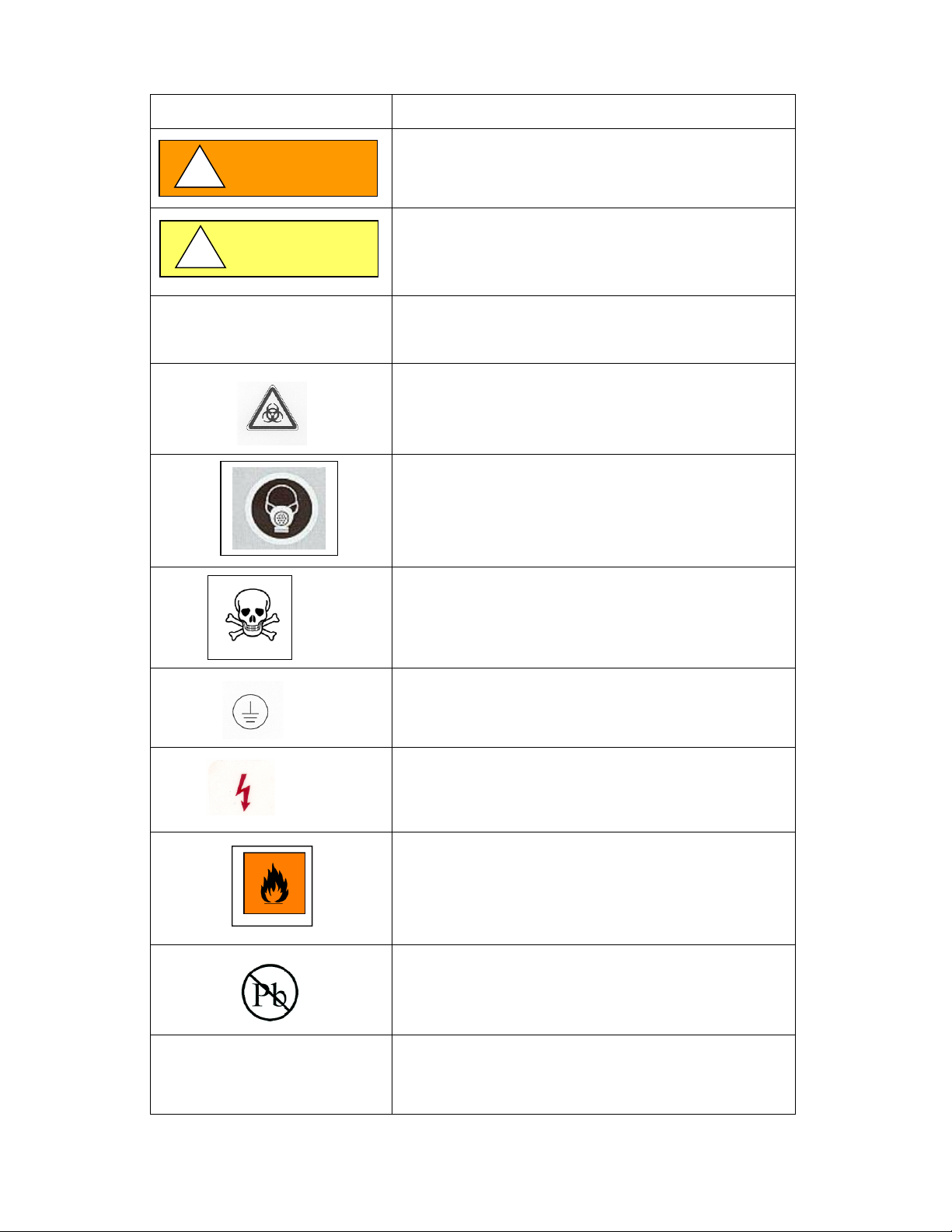
1.4 Explanation of Symbols
Symbol
Description
CAUTION
Safety alert symbol indicates a potentially hazardous
situation which, if not avoided, could result in death of
serious injury.
CAUTION
!
WARNING
!
Note: Used for important information
Biohazard
Hazardous Gases!
Personal Protection Equipment Required.
Chemical Hazard
Ground, Earth
Flammable Hazard
Potential electrical hazard,
only qualified person to access.
Lead Free
CAUTION used without the safety alert symbol
indicates a potentially hazardous situation which, if not
avoided, may result in property damage.
Safety alert symbol indicates a potentially hazardous
situation which, if not avoided, may result in minor or
moderate injury.
Page 8

OM0088 Page 8 of 38
April/2021
2.0 Models & Types
All NuAire FumeGard fume hoods are designed and built to be 100 percent free of all metals, including
nylon, using primarily stress relieved white polypropylene as well as other thermoplastics as required
(PVC,TFE, PVDF). Within this framework NuAire offers both the conventional fume hood and the by-pass
fume hood as a bench top style as standard. The fume hoods are manufactured in 4, 5, 6, or 8 foot
widths and offer a choice of either 25-1/2 or 31 1/2 inch work surface depths: A total of 16 different
configurations to choose from. The following are the dimensional characteristics for each model series:
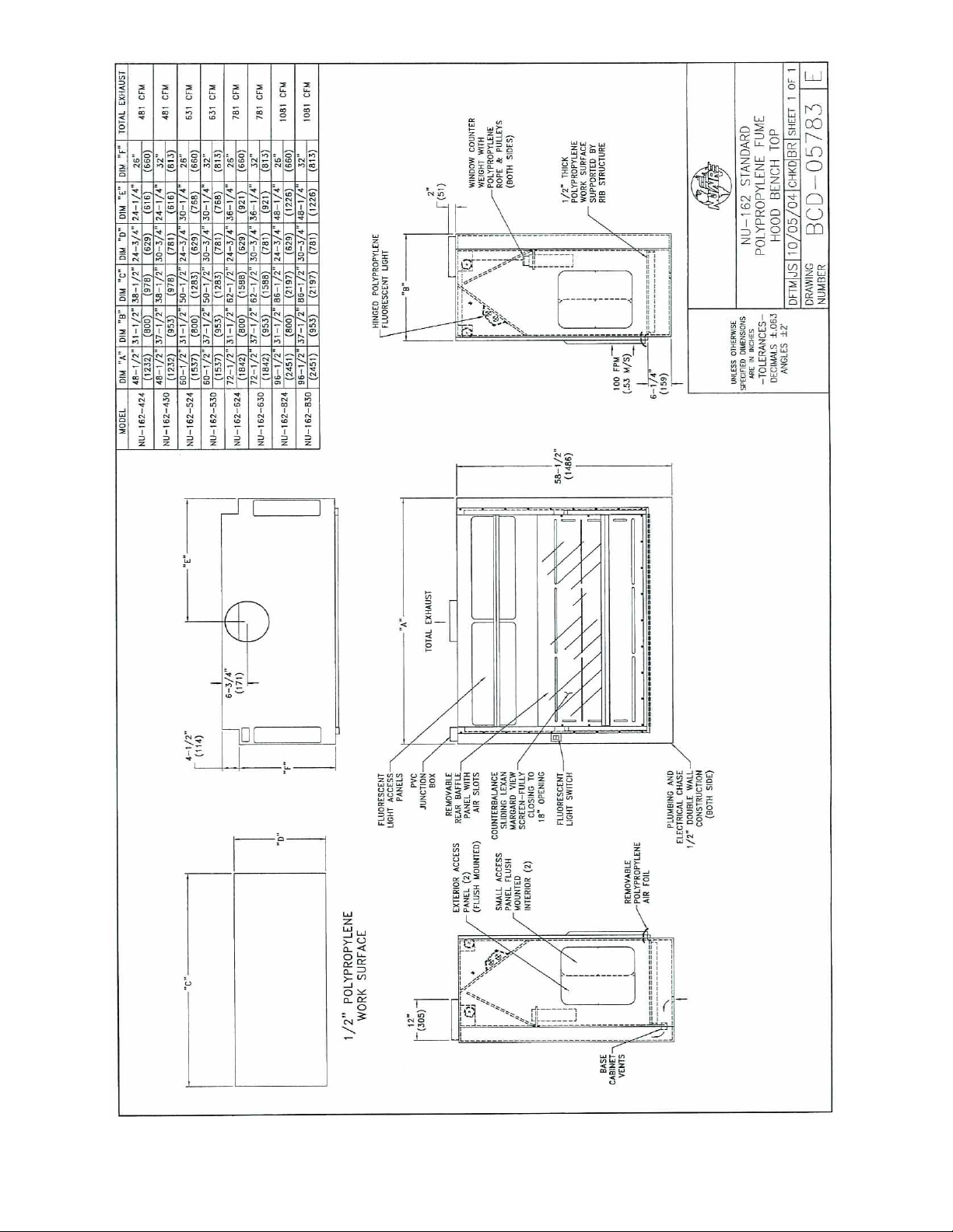
2.1 Model NU-162, 24" Bench Conventional Fume hood (Drawing BCD-05783)
2.2 Model NU-162, 30" Bench Conventional Fume hood (Drawing BCD-05783)
Overall Dimension
430
530
630
830
Inches (mm):
Width
48-½” (1232)
60- ½” (1537)
72- ½” (1842)
96- ½” (2451)
Depth
37- ½" (953)
37- ½" (953)
37- ½" (953)
37- ½" (953)
Height
(includes exhaust collar)
60-½” (1537)
60-½” (1537)
60-½” (1537)
60-½” (1537)
Work Area Dimensions
Width
38-½” (978)
50-½” (1283)
62-½” (1588)
86-½” (2197)
Depth
31-½" (800)
31-½" (800)
31-½" (800)
31-½" (800)
Height (average)
34” (864)
34” (864)
34” (864)
34” (864)
Height (peak)
48” (1219)
48” (1219)
48” (1219)
48” (1219)
Duct Opening
12” (305)
12” (305)
12” (305)
12” (305)
Exhaust CFM @ 100 FPM &
18" Window Access
481 CFM
631 CFM
781 CFM
1081 CFM
Overall Dimension
424
524
624
824
Inches (mm):
Width
48-½” (1232)
60- ½” (1537)
72- ½” (1842)
96- ½” (2451)
Depth
31- ½" (800)
31- ½" (800)
31- ½" (800)
31- ½" (800)
Height
(includes exhaust collar)
60-½” (1537)
60-½” (1537)
60-½” (1537)
60-½” (1537)
Work Area Dimensions
Width
38-½” (978)
50-½” (1283)
62-½” (1588)
86-½” (2197)
Depth
25-½" (648)
25-½" (648)
25-½" (648)
25-½" (648)
Height (average)
34” (864)
34” (864)
34” (864)
34” (864)
Height (peak)
48” (1219)
48” (1219)
48” (1219)
48” (1219)
Duct Opening
12” (305)
12” (305)
12” (305)
12” (305)
Exhaust CFM @ 100 FPM &
18" Window Access
481 CFM
631 CFM
781 CFM
1081 CFM
Page 9

OM0088 Page 9 of 38
April/2021
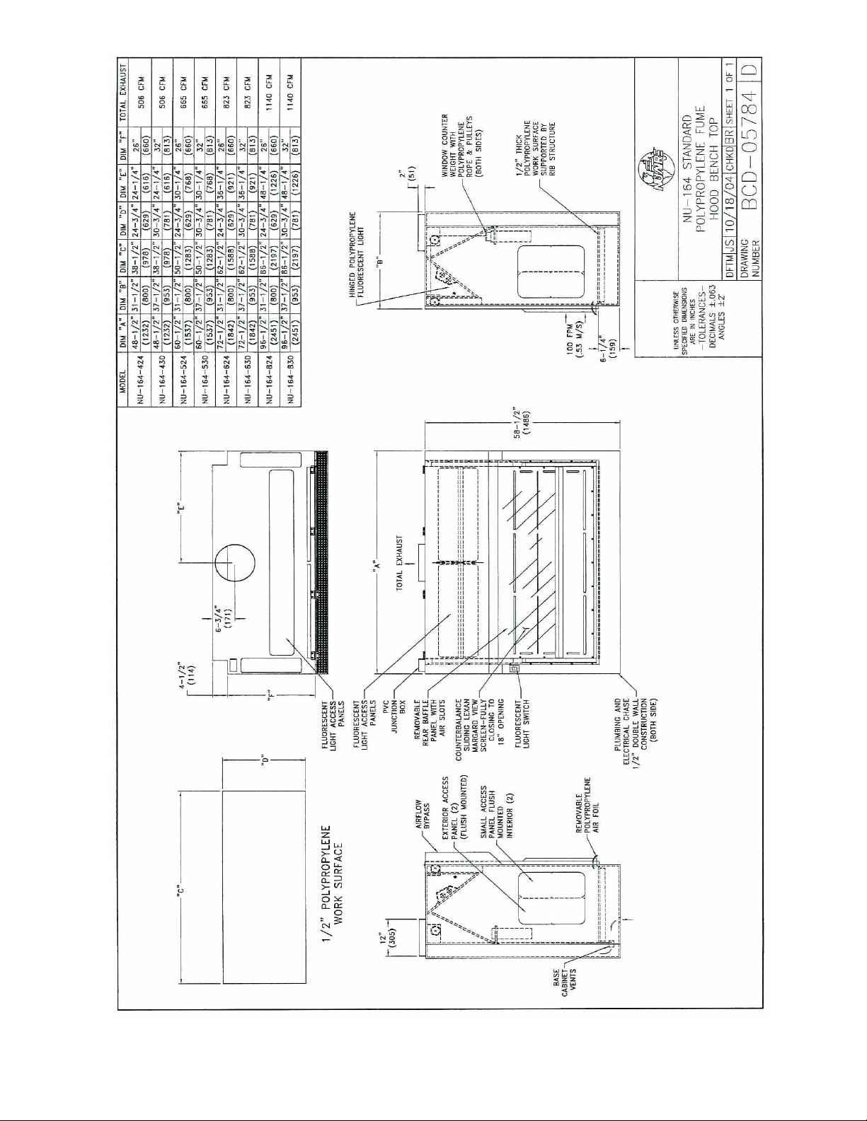
2.3 Model NU-164, 24" Bench By-Pass Fume hood (Drawing BCD-05784)
Overall Dimension
424
524
624
824
Inches (mm):
Width
48-½” (1232)
60- ½” (1537)
72- ½” (1842)
96- ½” (2451)
Depth
34- ½" (876)
34- ½" (876)
34- ½" (876)
34- ½" (876)
Height
(includes exhaust collar)
60-½” (1537)
60-½” (1537)
60-½” (1537)
60-½” (1537)
Work Area Dimensions
Width
38-½” (978)
50-½” (1283)
62-½” (1588)
86-½” (2197)
Depth
25-½" (648)
25-½" (648)
25-½" (648)
25-½" (648)
Height (average)
34” (864)
34” (864)
34” (864)
34” (864)
Height (peak)
48” (1219)
48” (1219)
48” (1219)
48” (1219)
Duct Opening
12” (305)
12” (305)
12” (305)
12” (305)
Exhaust CFM @ 100 FPM &
18" Window Access
506 CFM
665 CFM
823 CFM
1140 CFM
2.4 Model NU-164, 30" Bench By-Pass Fume hood (Drawing BCD-05784)
Overall Dimension
430
530
630
830
Inches (mm):
Width
48-½” (1232)
60- ½” (1537)
72- ½” (1842)
96- ½” (2451)
Depth
40- ½" (1029)
40- ½" (1029)
40- ½" (1029)
40- ½" (1029)
Height
(includes exhaust collar)
60-½” (1537)
60-½” (1537)
60-½” (1537)
60-½” (1537)
Work Area Dimensions
Width
38-½” (978)
50-½” (1283)
62-½” (1588)
86-½” (2197)
Depth
31-½" (800)
31-½" (800)
31-½" (800)
31-½" (800)
Height (average)
34” (864)
34” (864)
34” (864)
34” (864)
Height (peak)
48” (1219)
48” (1219)
48” (1219)
48” (1219)
Duct Opening
12” (305)
12” (305)
12” (305)
12” (305)
Exhaust CFM @ 100 FPM &
18" Window Access
506 CFM
665 CFM
823 CFM
1140 CFM
Page 10
OM0088 Page 10 of 38
April/2021
Page 11
OM0088 Page 11 of 38
April/2021
Page 12
OM0088 Page 12 of 38
April/2021
Page 13
OM0088 Page 13 of 38
April/2021
Page 14

OM0088 Page 14 of 38
April/2021
3.0 Construction Features
The following construction features apply to bench style fume hoods. Bench fume hoods consist of single
piece construction and can be placed on a customer bench or on an optional polypropylene base
provided for the fume hood (see BCD-05783 and BCD-05784.)
3.1 The fume hoods are constructed from all stress relieved, fully seam welded, and refrigerator white
polypropylene. The outer fume hood shell, inner workspace walls, spill trough plenum under work
surface (optional), and base cabinet floor are constructed with one half-inch polypropylene. The exhaust
duct, access panels, rear baffle, and front hood by-pass cover (as required) are constructed with
one-quarter inch polypropylene. All polypropylene walls/floors are reinforced where required to
maintain structural integrity.
3.2 The fume hoods are constructed to be 100% metal free and using absolutely no nylon components. The
basic construction is polypropylene, but depending upon customer requirements the following
thermoplastics may be used: (1) PVC, (2) polypropylene, (3) flame retardant polypropylene, (4) flame
retardant polyethylene, (5) PVDF Kynar or (6) TFE Teflon. Any customer requirement that dictates metal
to be used (i.e. such as black pipe for gas (may be epoxy coated or Teflon coated per customer direction).
3.3 Sliding vertical, fully counterbalanced sashes are provided as standard on all fume hoods. The sashes
provide for a work access opening from fully closed to 18 inches fully open. The sliding sash is
constructed of 1/4 inch (6mm) polycarbonate as standard, inset into polypropylene glide channels. A
“hard coat” is applied to Lexan to increase abrasive and chemical resistance. A counter weight balance,
encased in sealed PVC pipe is located in the plumbing chase. The counter weight is connected to the top
of the sash via polypropylene cable that rides over two machined polypropylene pulleys. Access panels
are provided on top of the hood for maintenance of the counterweight balance system. Alternative sash
materials are: (1) PVC, or (2) tempered glass.
3.4 The fume hoods are “double wall” construction, consisting of an outer wall separated by a 4-inch space
and the interior workspace wall of the fume hood. This area forms the plumbing chase for the routing
and connection of all services required in the fume hood, including electrical outlets. The plumbing
chase is a completely enclosed compartment. It is consistently under negative pressure, to minimize any
fume build-up that may occur.
3.5 Base storage cabinets are provided as an option with a compartmentalized shelf area and a large storage
area. The large storage area houses the plumbing for any sinks with a “P” trap installed per customer
requirements. A single fixed shelf is also provided. All base cabinet compartmentalized areas are vented
internally by vent tubes (one per compartment) via the exhaust plenum. The floor of the base cabinet
has a one half inch high lip to contain spills. Various size base cabinets are available and are shown per
illustration BCD-05967. The base can be attached to the fume hood with hardware per BCD-05957.
3.6 Leg levelers are provided on base units (quantity varies) and are constructed from 1-1/2 inch (38mm)
polypropylene rod stock. The leg levelers are adjustable from within the base storage cabinet and are
protected by a one-half-inch (13mm) raised lip and cap for spill containment. The leg levelers provide
adjustment for leveling the fume hood and can be adjusted with a 3/8 square ratchet extension.
3.7 Interior lighting is provided by two LED bulbs, built into a polypropylene hinged cover to provide access
for maintenance. The hinged cover is uses a gasket to prevent the migration of fumes into the light area.
A PVC light diffuser is provided in the interior. The LED light ballast is U.L. listed, electronic, and
thermally protected. It is housed in a polypropylene enclosure with all electrical wiring protected by U.L.
listed PVC flexible conduit. All electrical connections use PVC liquid-tight connectors to minimize direct
exposure to fume laden interior air (see Electrical Schematic BCD-08820 & BCD-19226).
Page 15

OM0088 Page 15 of 38
April/2021
3.8 Bench fume hoods can consist of any options illustrated by the customer drawing. Any of these options
are dictated by customer needs & requirements (i.e. sink sizes can vary in size or material.)
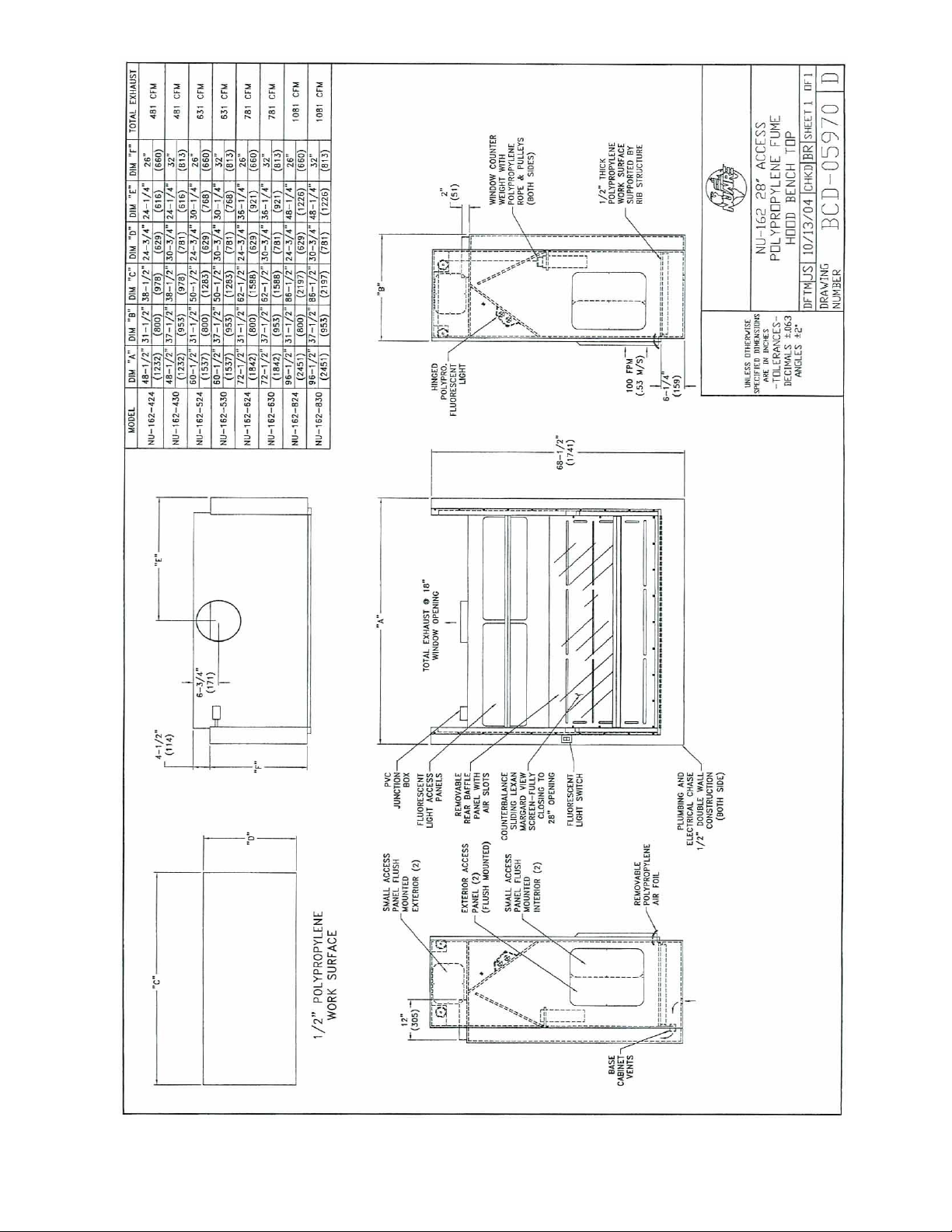
3.9 A special fume hood with a 28-inch (711mm) window access opening is available for customers who
require more front window clearance for special equipment. The maximum 18-inch (457mm) work
access should still be maintained to correlate with exhaust flow specifications. This special fume hood is
illustrated per BCD-05970, BCD-10434 drawing.
3.10 Some locations have required codes necessary in securing their fume hood to their building structures.
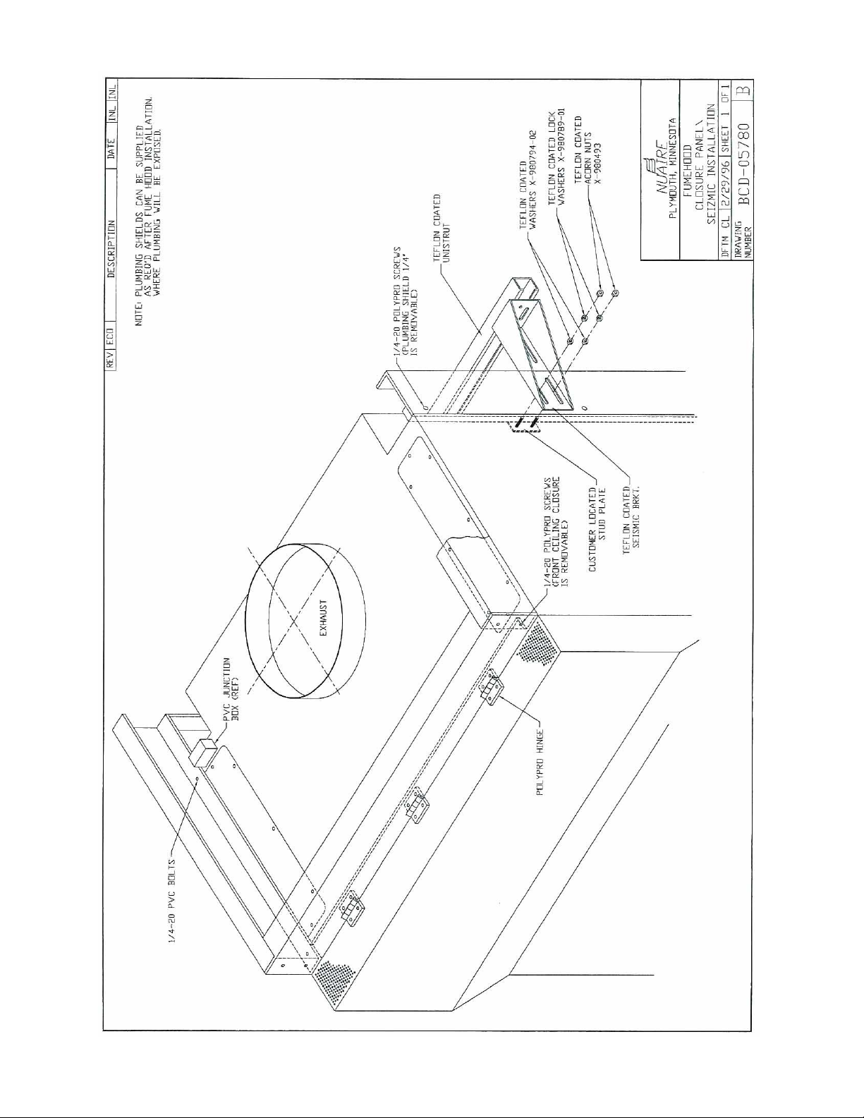
BCD-05780 represents seismic securing of the fume hood to the wall. This drawing also portrays optional
polypropylene ceiling closure panels and rear plumbing polypropylene closures that hide any obvious
plumbing at the fume hood rear.
Page 16

OM0088 Page 16 of 38
April/2021
4.0 Warranty
Details regarding product warranties can be found in the published warranty data separate from this
manual and included within the data packet sent with the unit.
5.0 Shipments
NuAire takes every reasonable precaution to assure that your Fume hood arrives without damage.
Motor carriers are carefully selected and shipping cartons have been specially designed to insure your
purchase. However, damage can occur in any shipment and the following outlines the steps you should
take on receipt of a NuAire Fume hood to be sure that if damage has occurred, the proper claims and
actions are taken immediately.
5.1 Damaged Shipments
5.1.1 Terms are factory, unless stated otherwise. Therefore, it is important to check each shipment
before acceptance.
5.1.2 If there is visible damage, the material can be accepted after the driver makes a notation on the
consignee’s copy of the freight bill. Then an inspection must be made to verify the claim against
the carrier. This inspection is the basis of your filing the claim against the carrier.
5.1.3 If concealed damage is found, it is absolutely necessary to NOTIFY THE FREIGHT AGENT AT ONCE
and request an inspection. Without this inspection, the transportation company may not accept
a claim for loss or damage. If the carrier will not perform the inspection, an affidavit must be
prepared stating that he was contacted on a certain date and that he failed to comply with the
request. This along with other papers in the customer’s possession will support the claim.
Page 17
OM0088 Page 17 of 38
April/2021
6.0 Installation Instructions
6.1 Location
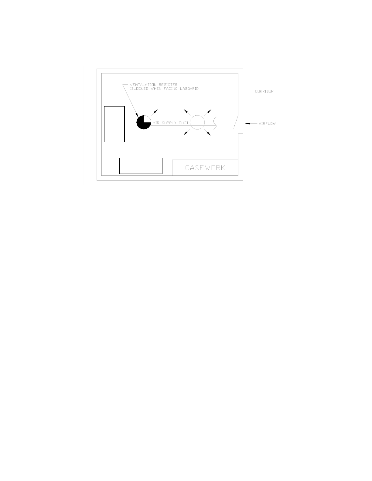
Within the laboratory, production process, etc., the ideal location for the FumeGard fume hood is away
from personnel traffic lanes, air vents (in or out), doors and/or any other source of disruptive air
currents.
If drafts or other disruptive air currents exceed the intake velocity of the fume hood through the access
opening, the potential exists for contaminated air to exit or enter the work surface area of the fume
hood. It depends on the severity of the air current. Remember, the FumeGard fume hood is no
substitute for good laboratory technique. Supply makeup air should be evenly diffused into the room at
a rate not to exceed 75 LFPM (.38 m/s), and never “blasted” directly at the floor.
Where space permits, it is recommended to provide a clear 6-inch (152mm) area on each side of the
fume hood for maintenance purposes.
The electrical outlet into which the fume hood is connected should be readily accessible for maintenance
purposes. Do not position the fume hood to prevent access to the power cord. The power cord plug
serves as the disconnect and should remain readily accessible. If the outlet is inaccessible, such as a
conduit (hardwired) connection, then an appropriate warning label should be applied near the fume
hoods on/off switch, to indicate the circuit breaker on the power distribution panel to be used.
FUMEGARD
LOCATION
FUMEGARD
LOCATION
Page 18

OM0088 Page 18 of 38
April/2021
As with all types of fume hoods, the FumeGard NU-162 and NU-164 requires careful site planning and
preparation, due to the total exhaust nature of the fume hood. Proper sizing of the exhaust and supply
systems are critical to the successful installation of the fume hood. In addition, the fume hood provides
for the choice of makeup air for the supply (downflow air). The following are airflow requirements:
Supply Air
Exhaust Air **
NU-162-424/430
481 CFM (818 CMH)
481 CFM (818 CMH)
NU-162-524/530
631 CFM (1073 CMH)
631 CFM (1073 CMH)
NU-162-624/630
781 CFM (1328 CMH)
781 CFM (1328 CMH)
NU-162-824/830
1081 CFM (1838 CMH)
1081 CFM (1838 CMH)
NU-164-424/430
506 CFM (860 CMH)
506 CFM (860 CMH)
NU-164-524/530
665 CFM (1130 CMH)
665 CFM (1130 CMH)
NU-164-624/630
823 CFM (1399 CMH)
823 CFM (1399 CMH)
NU-164-824/830
1140 CFM (1938 CMH)
1140 CFM (1938 CMH)
*CFM exhaust at 0.8 inches (8mm) w.g. negative for 4 ft. models.
CFM exhaust at 0.8 inches (10mm) w.g. negative for 5 ft. models.
CFM exhaust at 0.8 inches (13mm) w.g. negative for 6 ft. models.
CFM exhaust at 1.5 inches (20mm) w.g. negative for 8 ft. models.
6.2 Set-Up Instructions
Remove outer shipping protection (carton or crating). The fume hood is fastened to the base skid and it
is usually the best procedure to leave the skid in place until the fume hood is located in its approximate
position to facilitate ease in handling. It can then be removed from the skid by removing the banding
holding the fume hood to the skid.
6.2.1 Base Cabinet Assembly (BCD-05957/67)
The base cabinet is shipped on a separate skid if accompanied with the fume hood. Remove the
banding holding the base cabinet to the base skid. Lift the base cabinet from the skid and place
on the floor. Now lift the fume hood on top of the base cabinet and bolt the base cabinet to the
fume hood using (4) 1/4-20 x 1-1/2” bolts and washers provided for the attachment process.
6.2.2 Leveling
Using a level placed on the work tray, adjust the leg levelers, first, end-to-end then front to back.
The leg levelers located on the floor of the base cabinet are adjusted using a 3/8” drive socket
and rotating to raise or lower as necessary.
6.2.3 Bench Installation
Place the fume hood on the bench. Using RTV caulk, seal all around the base of the fume hood
and the bench. This provides a tight seal to prevent bench spills from migrating under the fume
hood.
6.2.4 Electrical Service
The NU-162/164/E all Polypropylene Fume hoods may be "hardwired" (optional) or plugged into
an outlet with protective earthing connection with the standard power cord. The fume hood
requires 115 or 230VAC, 50 or 60Hz single phase (correct rating varies per fume hood size,
reference Electrical/Environmental Requirements).
It is recommended that power to the fume hood, whether hardwired or plug connected, be on
its own branch circuit, protected with a circuit breaker at the distribution panel near the fume
hood.
Page 19

OM0088 Page 19 of 38
April/2021
6.2.5 Plumbing Services
Remote controlled polypropylene needle-valve plumbing fixtures are provided within the side
walls of the fume hood with control handles located external on the face of the fume hood. The
type of service is specified by the colored-wall petcock (i.e. air, gas, vacuum, nitrogen, etc.)
Service outlets within the interior are designed for hose connections with ten serrations.
All plumbing services are plumbed within the right or left chase with 1/2 inch flexible
polypropylene tubing and compression fittings. Water service plumbing lines are rated at a
maximum of 60 PSI (4.5 Bars) as tested at NuAire before shipment. Air and gas lines are tested at
a 90 PSI (6.75 Bars) maximum.
All plumbing terminates at the rear of the fume hood (for customer hook-up) with 1/2 inch
female NPT polypropylene couplings.
All sinks are plumbed with 1-1/2 inch polypropylene “P” trap and piping that exits out the rear of
fume hood in the storage area. A rear access panel is provided for drain connection.
Connection to plant utilities should be made with proper materials for the individual service and
according to national and/or local codes. It is not recommended that flammable gases be used in
the fume hood unless flame retardant polypropylene is purchased; however, if flammable gas is
used, emergency shutoff valves should be located in an accessible area external to the fume
hood. Observe all labels pertaining to the type of services and operating pressure.
6.2.6 Exhaust/Supply Duct Installation Guidelines
The exhaust/supply systems must provide conditions similar to that under which the fume hood
was certified to meet its stated performance. The following guidelines should be observed when
installing exhaust/supply air duct work of either existing plant exhaust systems, or a new exhaust
system.
1) Adequate room air inflow to replace exhausted air. Air diffusion rate should not to
exceed velocity of 105 LFPM (.53 m/s).
MAKEUP AIR REQUIREMENTS
Supply Air
NU-162-424/430
481 CFM (818 CMH)
NU-162-524/530
631 CFM (1073 CMH)
NU-162-624/630
781 CFM (1328 CMH)
NU-162-824/830
1081 CFM (1838 CMH)
NU-164-424/430
506 CFM (860 CMH)
NU-164-524/530
665 CFM (1130 CMH)
NU-164-624/630
823 CFM (1399 CMH)
NU-164-824/830
1140 CFM (1938 CMH)
2) Adequate plant exhaust system capability. The exhaust system is usually adequate if it
can provide the rated exhaust flow at 1.0 inches water gauge negative.
3) Adequate supply air capability (if used). The supply air system is usually adequate if it
can provide the rated supply air at 0.0 inches water gauge positive.
4) All duct losses must be considered in selecting the exhaust blower, for a new exhaust
system (i.e. duct diameter, length and number of elbows.)
Page 20

OM0088 Page 20 of 38
April/2021
5) All duct work should be securely anchored to the building construction in a manner to be
free from vibration and swaying under all conditions of operation.
6) Sheet metal gauges and seams should be in accordance with the current edition of the
ASHRAE guide. A minimum of 24 gauge is required to prevent duct collapse due to high
static pressure conditions, required.
7) All duct work should be maintained at a negative pressure within the building (i.e.
externally located exhaust blower).
8) The exhaust blower and duct work should be a sealed system, properly vented to the
atmosphere to disperse exhausted air.
9) The exhaust duct should be dampered. Dampers should be installed with a locking
quadrant with markings to indicate damper position. A polypropylene damper system is
available and is located in the upper duct extension.
6.2.7 Final Assembly and Inspection
Remove any remaining packaging materials, tape. etc. along with the window sash and counter
balance blocking with in the right and left side service chase. Inspect all fume hood surfaces,
service connections and sash assembly operation, rope and counter balance. Lastly, the exterior
surfaces and viewing window are easily cleaned with any mild household detergent using a soft
cloth. Harsh chemicals, solvent-type cleansers and abrasive cleaners should not be used. Fume
Hood interior walls or work surfaces are easily cleaned with any household detergent using a soft
cloth. The work surface is removable for access to the sloped drain plenum area for cleaning. The
interior should be thoroughly cleaned prior to use. A solution of 70% isopropyl alcohol is suitable
for a final cleaning process.
6.3 Testing Methods and Equipment
After installation and prior to use, NuAire recommends that the fume hood be annually recertified to
factory standards. At a minimum the following tests should be performed.
1. Airflow velocities 2. Airflow smoke patterns
Of these tests, in order to ensure that no disruptive air currents are penetrating the air inflow barrier
smoke flow tests must be performed at a minimum (only tracer gas can confirm containment). These
tests must result in the containment of smoke passed around the perimeter of the work access opening,
as well as no refluxing or drift of smoke within the interior of the fume hood.
NOTE: IT IS RECOMMENDED THAT THESE TESTS BE PERFORMED BY A QUALIFIED TECHNICIAN WHO IS
FAMILIAR WITH THE METHODS AND PROCEDURES FOR TESTING FUME HOODS (SEE
INSERT).
NOTE: AFTER THE INITIAL CERTIFICATION, NUAIRE RECOMMENDS THAT THE CABINET BE RECERTIFIED AT
A MINIMUM OF AN ANNUAL BASIS AND AFTER EVERY FILTER CHANGE, MAINTENANCE ACTION,
OR ANY TIME THE OPERATOR FEELS IT IS NECESSARY.
The FlowGard fume hoods provide premium performance. Quality control in both design and
manufacturing ensure superior reliability; however, protection to both product and operator is
so vital that certification to the performance requirements should be accomplished as stated to
ensure personnel safety as established by the factory standards.
Page 21
OM0088 Page 21 of 38
April/2021
Page 22
OM0088 Page 22 of 38
April/2021
Page 23

OM0088 Page 23 of 38
April/2021
7.0 General Maintenance
All maintenance actions on this equipment must be performed by a qualified
technician who is familiar with the proper maintenance procedures required
for this equipment. This includes certification, inspection as well as repair.
7.1 LED Lamp Replacement
Two LED lamps are in a sealed enclosure external to the Fume Hood work zone to aid maintenance
and minimize heat buildup within the Fume Hood. The life rating of the lamp is 9000 hours based on
three-hour burning cycles.
To replace the lamp it is necessary to remove the lamp fixture assembly.
1) Switch Fume Hood light switch off and access through either top service panel or through
bypass open area under the front decorative hinged panel.
2) Lamp cover is hinged and held in place with fasteners. Remove fasteners and hinge up to
access lamps for replacement.
3) Lamps are removed by pressing to one side for release. Reverse the procedure for new lamp
installation.
7.2 Preventative Maintenance
The Fume Hood preventative maintenance inspection procedures should be performed annually during
The certification and consist of a physical examination of the work zone interior condition and
cleanliness. Sash operation and condition, rope, counter balance, light operation and service fixture
ware and function. Inspection results should be recorded with the certification results.
7.3 Test Performance and Procedures
All equipment is thoroughly inspected at the NuAire factory at the time of shipment. Quality control is
maintained by constant surveillance over the product beginning at the receipt of purchased material and
concluding with a final inspection. In all instances where product quality cannot be easily assessed on
the end item, the product is inspected during sub-assembly fabrication.
Inflow velocity is determined to certify fume hood performance to SEFA – 5th Edition Desk Reference as
described below.
7.3.1 SEFA – 5th Edition Desk Reference
7.3.1 Face Velocity
Using a TSI Thermoanemometer Model 8355 or equivalent, determine hood face velocity by
averaging velocity readings taken in the vertical plane defined by the bottom of the sash. Face
velocity readings shall be taken on a 6-inch (152mm) vertical and horizontal grid. No individual
point reading may vary more than 20 percent.
CAUTION
!
Page 24
OM0088 Page 24 of 38
April/2021
7.3.2 Smoke Flow Patterns
With a smoke stick or cotton swab dipped in titanium tetrachloride and the hood sash in the
open position verify all smoke is contained by fume hood. A complete transverse, 1-1/2 inches
(38mm) outside hood face and a complete transverse 6-inches (152mm) inside the fume hood.
Also verify that all airflow is flowing into the work zone and no refluxing (reverse flow) occurs,
particularly against hood sidewalls.
CAUTION: Titanium tetrachloride fumes are toxic and corrosive, use sparingly,
avoid inhalation and exposure to body, clothing, and equipment that
might be affected by corrosive fumes
7.3.3 Smoke Bomb
A. Place a 60 second smoke bomb on the work surface and ignite. Move the sash up and
down and verify that no smoke escapes the face. As the window is closed you may note
a rolling or turbulence within the hoods interior for a conventional hood.
B. With a tong or other suitable tool, pick up the smoke bomb with the sash fully open and
direct smoke across the work surface, against the sidewalls and rear baffle. All smoke
should be contained within the fume hood and be rapidly exhausted.
Page 25

OM0088 Page 25 of 38
April/2021
7.4 ASHRAE Standard 110-2016
NuAire has conducted this test on representative production models in order to validate the design and
containment properties of the design under ideal laboratory conditions, as manufactures. NuAire will
periodically conduct these tests as a Quality Assurance measure to validate current production models as
well as after any significant design change (i.e. baffle configuration, interior height changes, etc.) Fume
hoods so tested are labeled prior to shipment. These tests may also be conducted at customer request
and expense or by contract obligation.
7.4.1 Procedure
A vapor ejector is placed 6 inches (152mm) behind the view screen and allowed to release a
tracer gas (sulfur hexafluoride) at a rate of 4 liters per minute. The ejector releases the tracer gas
mixed with fume hood air approximately 11 inches (279mm) above the work surface. A
mannequin is placed in front of the view screen with the tip of its nose placed within 3 inches
(76mm) of the view screen. A continuous sample of air from the mannequin breathing zone is
monitored by an infrared gas analyzer which reads absorbency at the analytical wavelength of
the tracer gas. The mannequin and ejector challenge the fume hood at the center and both right
and left sides.
The Hood Performance Rating is specified to be the concentration of the tracer gas measured in
the breathing zone at the challenged flow rate.
7.4.1 Results
The Hood Performance Rating is reported in the following format XX/AU/M YYY:
Where:
XX= Tracer release rate in hood using the specified diffuser apparatus.
Rates are as follows:
1 liters/minute approximates pouring volatile solvents back and forth from one
beaker to another.
4 liters/minute is an intermediate rate between 11 pm and 81 pm.
8 liters/minute approximates violently boiling water on a 500-watt hotplate.
(Other release rates can be specified for special cases.)
YYY= Control level, ppm, at the breathing zone of the worker.
AU/M= “as used” in the laboratory. “AM” would indicate “as manufactured in the
manufacturer’s test room.
Page 26

OM0088 Page 26 of 38
April/2021
8.0 Electrical/Environmental Requirements
8.1 Electrical (Supply Voltage Fluctuations not to Exceed +/- 10%)
8.2 Operational Performance (for indoor use only)
Environment Temperature Range: 60°F-85°F (15°C – 30°C)
Environment Humidity: Maximum relative humidity 80% for temperatures up to 31°C
decreasing linearly to 50% relative humidity at 40°C
Environment Altitude: 6562 Feet (2000M) maximum
8.3 Light Exposure
Standard LED Lighting @ 150 ft. candles (1614 LUX) maximum intensity.
8.4 Installation Category: 2.0
Installation category (overvoltage category) defines the level of transient overvoltage, which the
instrument is designed to withstand safely. It depends on the nature of the electricity supply and its
overvoltage protection means. For example, in CAT II, which is the category used for instruments in
installations supplied from a supply comparable to public mains such as hospital and research
laboratories and most industrial laboratories, the expected transient overvoltage is 2500 V for a 230 V
supply and 1500 V for a 120 V supply.
8.5 Pollution Degree: 2.0
Pollution degree describes the amount of conductive pollution present in the operating environment.
Pollution degree 2 assumes that normally only non-conductive pollution such as dust occurs with the
exception of occasional conductivity caused by condensation.
8.6 EMC Performance (classified for light industrial)
Emissions: EN61326
Immunity: EN61326
Class A equipment is intended for use in an industrial environment.
In the documentation for the user, a statement shall be included
drawing attention to the fact that there may be potential difficulties in
ensuring electromagnetic compatibility in other environments, due to
conducted as well as radiated disturbances.
NU-162/164-424/430/E
115/230 VAC,
50/60 Hz,
1 Amp
NU-162/164-524/530/E
115/230 VAC,
50/60 Hz,
1 Amp
NU-162/164-624/630/E
115/230 VAC,
50/60 Hz,
1 Amp
NU-162/164-824/830/E
115/230 VAC,
50/60 Hz,
1 Amp
WARNING
!
Page 27

OM0088 Page 27 of 38
April/2021
9.0 Selection of Hood Face Velocity
The interaction of (1) room air supply distribution, (2) operations/manipulations within the fume hood
and (3) fume hood face velocity makes any specific (target) fume hood face velocity inappropriate. These
interactions occur as a result of the following:
A) For typical operations within fume hoods the laboratory technician stands at the face of the hood and
manipulates apparatus in the hood. As air is drawn into the hood face around the workers body, eddy
currents form downstream (i.e. between the hood face and the worker’s body). Depending on body
width and inflow velocity, the eddy currents may project into the hood face dragging out contaminates
to the body and up to the breathing zone. In general; the higher the face velocity the greater the eddy
currents will be. For this reason, higher face velocities do not necessarily result in improved protection.
B) The distribution of supply air into the laboratory as well as room air currents has a large effect on hood
performance. Personnel walking within three feet of the hood face can generate cross draft velocities
exceeding 175 feet per minute (0.89 m/s). In addition, improper diffusion of supply air and/or
insufficient supply air may cause cross drafts that exceed the hood face velocity. All disruptions that
exceed hood face velocity may force contaminated interior fume hood air to escape into the laboratory
and into the worker’s breathing zone.
C) ASHRAE research project RP-70, conducted by Caplan and Knutson reached the following conclusions:
1. Lower breathing zone concentrations can be attained at 50 cfm/sq. ft. face velocities with good
air supply distribution than at 150 cfm/sq. ft. with poor air distribution. With a good air supply
system, and tracer gas released at 8 liters per minute inside the hood, breathing zone
concentrations can be kept below 0.1 ppm and usually below 0.01 ppm.
2. The terminal throw velocity of supply air jets should be no more than 1/2 to 2/3 the hood face
velocity; such terminal throw velocities are far less than conventional practice.
3. Perforated ceiling panels provide a better supply system than grills or ceiling diffusers in that the
system design criteria are simpler and easier to apply and precise adjustment of the fixtures is
not required.
For the reasons described above, increased hood face velocities may be self-defeating because the
increased air volume handled through the room makes the low velocity distribution of supply air more
difficult.
NuAire specifies the exhaust requirements at maximum sash opening and with an average inflow velocity
of 100 LFPM (0.51 m/s). This should be adjusted based on the above considerations for each application.
Page 28
OM0088 Page 28 of 38
April/2021
10.0 Perchloric Acid Hoods
The properties of perchloric acid heated above ambient temperatures require that a specially designed
fume hood be set aside for exclusive use with the material. This hood should be labeled “For Perchloric
Acid Operations Only” per NFPA 45, paragraph 6.12.1.
Perchloric acid hoods are equipped with cold water spray devices for the washdown of all surfaces
exposed to perchloric acid fumes. NuAire provides for the washdown of the internal exhaust plenum
behind the removable rear baffle via three 3/4-inch polypropylene spray head pipes equally spaced in the
plenum. A 1-1/2-inch (38mm) drain is provided in the bottom of the plenum for the disposal of waste
water. Interior work zone surfaces must be manually cleaned with water. A separate drain trough is
provided in the rear of the work surface for waste water collection, draining back into the exhaust
plenum.
As much as possible the duct work for perchloric acid hoods and exhaust systems should take the
shortest and straightest path to the outside of the building and should not be manifolded with other
exhaust systems. Horizontal runs should be as short as possible, with no sharp turns or bends. The duct
run from the exhaust blower to the hood should provide a positive drainage slope back to the hood,
however, a separate drain should be provided for the collection of duct waste water. All ductwork
should consist of completely sealed sections, use no flexible connectors, and be acid resistant and
non-reactive with perchloric acid. The exhaust fan must be acid resistant and non-reactive with
perchloric acid. The exhaust fan must be acid resistant, non-sparking and the fan motor must not be
located within the ductwork or exposed to acid fumes.
Frequency of washdown, both hood and exhaust system, is determined by the usage and concentration
of reagents. This can range from a weekly procedure to one that occurs during or after every use.
Washdown should always be followed by an inspection to verify that all areas are clean and that wash
system is functioning properly.
Some of the hazards of perchloric acid which justify the use of a special hood are:
1. Perchloric acid is a very strong acid, capable of producing severe burns when in contact with skin,
eyes, or respiratory tract.
2. As an aqueous solution it can cause violent explosions if improperly handled.
3. It reacts with other substances to form unstable materials which are susceptible to exploding
either by impact, friction, or spontaneous combustion.
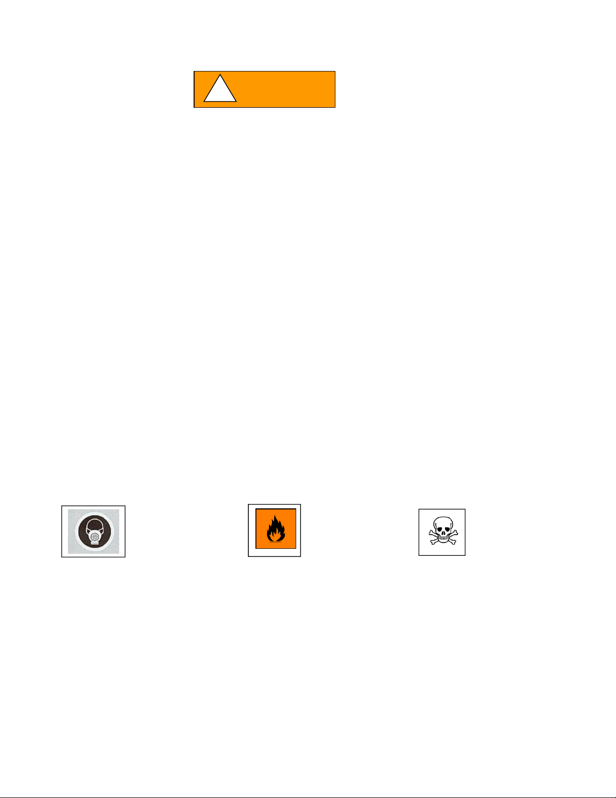
Hazardous Gases!
Personal Protection
Equipment
Required.
WARNING indicates a potentially hazardous
situation which, if not avoided, could result
in death of serious injury.
Chemical Hazard
Flammable Hazard
WARNING
!
Page 29

OM0088 Page 29 of 38
April/2021
Persons using perchloric acid should be thoroughly familiar with its hazards. Many reported laboratory
accidents have involved less than one gram of reactant. Listed below are some common safety practices
that should be followed.
1. Spilled perchloric acid should be thoroughly washed away with large amounts of water.
2. The use of organic chemicals or materials in the hood should be avoided.
3. Goggles or other effective eye protection should be used whenever possible, as well as utilization
of the fume hood sash for additional safety.
4. Gas flames or oil baths should not be used within the hood.
5. Organic chemicals should not be kept in storage areas set aside for perchloric acid storage.
6. A schedule should be made for regular washdown and inspection of hood interior, ductwork, and
blower to guard against a build-up of dangerous perchloric materials.
7. Only fluorocarbon grease should be used as a blower lubricant, since any other type is to be
considered potentially hazardous.
8. Washdown procedure should be performed after completion of usage with all apparatus
removed from hood.
Page 30
OM0088 Page 30 of 38
April/2021
!
CAUTION
NOTE:
11.0 Disposal and Recycle
Cabinets that are no longer in use and are ready for disposal contain reusable materials. ALL
components with the exception of the HEPA filters may be disposed and/or recycled after they are
known to be properly disinfected.
Follow all local, state and federal guidelines for disposal of HEPA filter solid waste.
Prior to any disassembly for disposal,
the cabinet must be decontaminated.
Component
Material
Base Cabinet
Polypropylene
Window
Polycarbonate
Printed Wiring Assembly
Lead Free Electronic
Wire
PVC Coated Copper
Controls
LED Lamp
Various Steel, electronic
Various plastic, electronic
Armrest
Polypropylene
Connectors
Nylon
Hardware
Teflon Coated Stainless Steel and Steel
Material type can be verified with use of a magnet with stainless and aluminum being
non-magnetic.
NOTE:
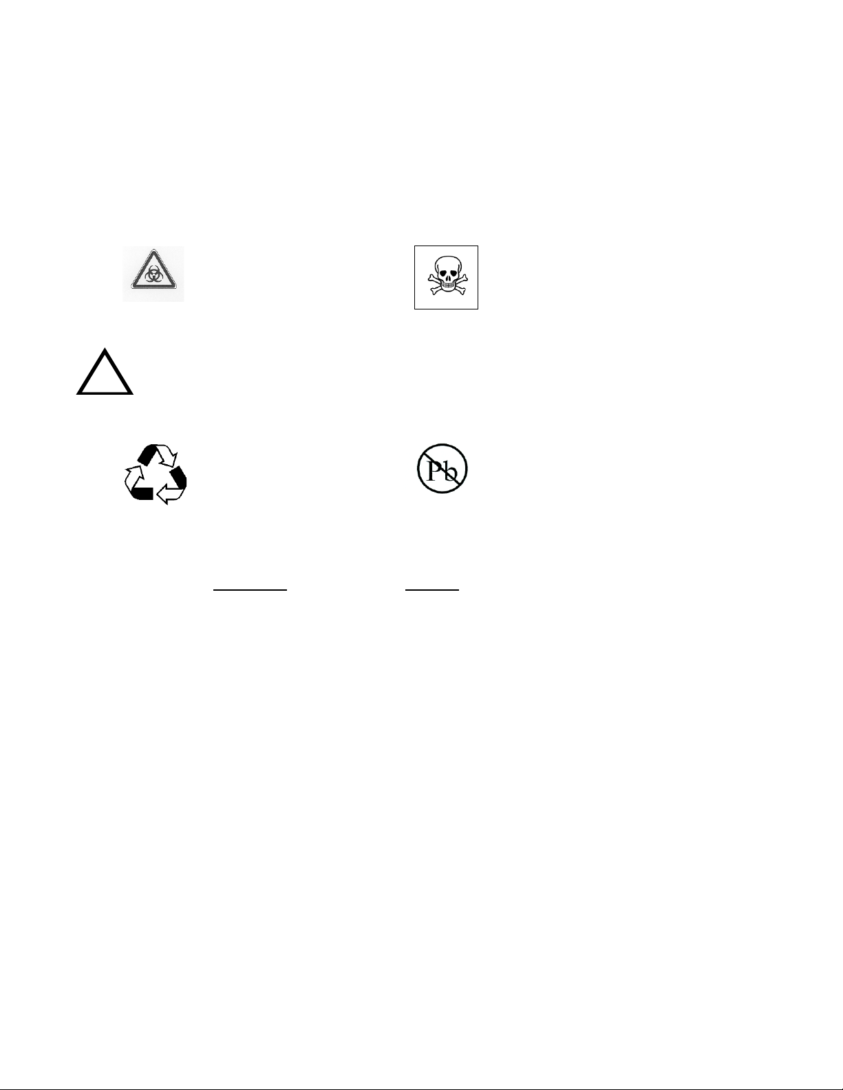
BIOHAZARD
RECYCLE
LEAD FREE
Chemical Hazard
Page 31

OM0088 Page 31 of 38
April/2021
12.0 Polypropylene
NuAire products manufactured from Polypropylene materials require special consideration for the care
and use to assure maximum customer satisfaction. Polypropylene materials have many favorable
characteristics, such as being resistant to many chemicals, rigid, durable, and available in many
thicknesses. NuAire fabricates the Polypropylene materials in many different ways to produce a variety
of products for the laboratory. Understanding about the care and use of the Polypropylene material is
important.
12.1 Cleaning
Cleaning laboratory equipment is important in terms of both functionality and general good
housekeeping. The information provided below is intended to aid the development of facility
Standard Operating Procedures (SOPs) for cleaning equipment. It is strongly recommended that
all cleaning materials used be tested and verified in terms of both effectiveness and material
compatibility before they are written into the cleaning SOP documentation.
Note: NuAire does not offer any product warranty with respect to cleaning material
compatibility. USE AT YOUR OWN RISK! The information provided above is from raw material
suppliers and known general source documents for use to develop application cleaning SOPs.
12.2 Material Compatibility
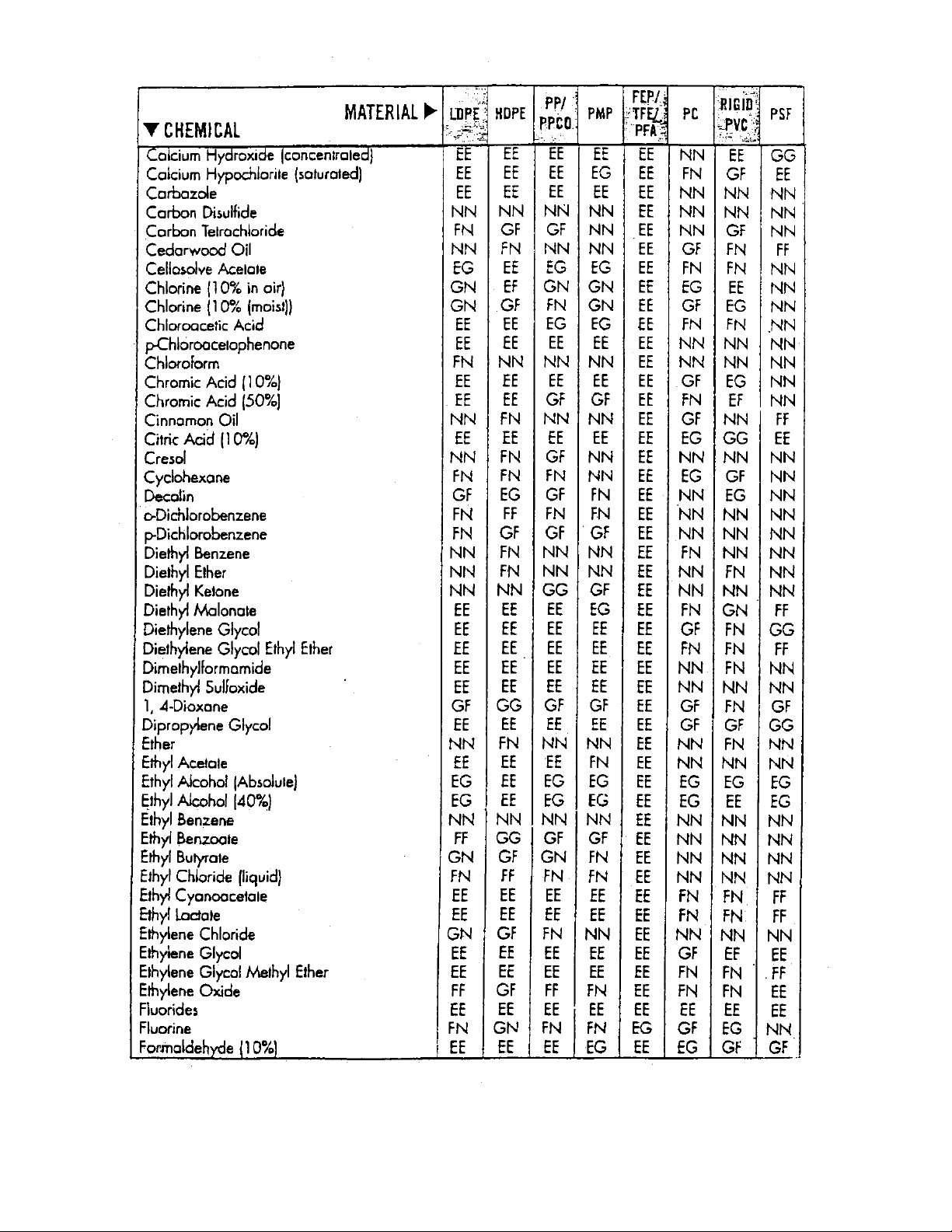
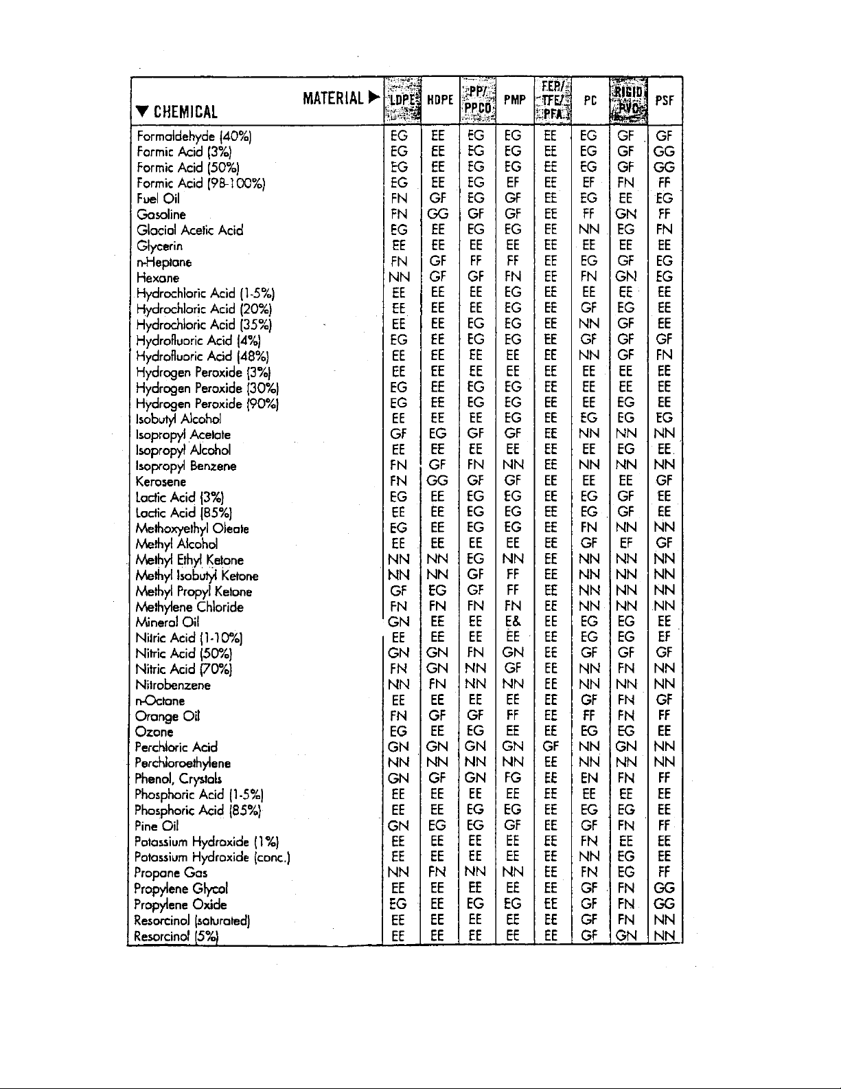
High concentrations of some acids may cause staining if in the constant contact with
polypropylene. Once it has penetrated the surface of the material, only option would be to
replace the surface, if at all possible.
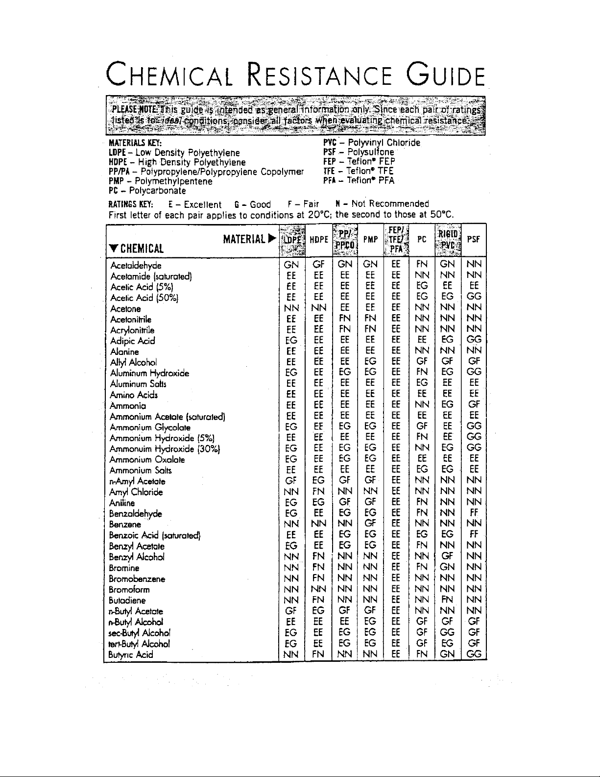
See chemical resistance guide on following page for Polypropylene and other various types of
plastics.
Page 32
OM0088 Page 32 of 38
April/2021
Page 33
OM0088 Page 33 of 38
April/2021
Page 34
OM0088 Page 34 of 38
April/2021
Page 35
OM0088 Page 35 of 38
April/2021
Page 36
OM0088 Page 36 of 38
April/2021
Page 37
OM0088 Page 37 of 38
April/2021
Page 38
OM0088 Page 38 of 38
April/2021
 Loading...