

Page 1
A
50mm
B
F
C
E
Rectangular spigots
(size NALTF 18-24)
Circular
spigots
(NALTF 9-17)
D dia
Removable top
panel
A
B
Removable
top panel
Opposed
outlet
grilles
F
E
Control module
located internally
Bottom inlet
C
Louvred
end outlet
Bottom rectangular
inlet spigot
F
E
B
A
C
NALTF & NALTRF
Belt Drive Roof and Plantroom Twinfans
Installation and Maintenance
The EMC Directive
2014/30/EU
The Low Voltage
directive
2014/35/EU
Introduction
The Nuaire NALTF and NALTRF Belt Drive Twinfan range
consists of the following units:
NALTF/NALTRF Plantroom/Roof in line mounted unit.
NALTRF Plantroom/Roof bottom inlet unit.
NALTRF Plantroom/Roof bottom/end inlet unit .
(Larger sizes).
Units are rectangular in section and the casing is
manufactured from heavy gauge ‘Aluzinc’ aluminium-zinc
coated mild steel.
A full size internally lined access panel is fitted to the top
face and is fully detachable for inspection purposes.
The motor plate and frames are supported on the base by
resilient mountings allowing the fan unit to be operated
without the need for separate anti vibration fan case
mountings.
The units incorporate two independent motors with high
efficiency, forward curved centrifugal impellers running in
metal scrolls. Taperlocked pulleys and wedge drive belts are
employed. The fans discharge into a common outlet chamber
through a shutter system that prevents ‘blowback through
the standby fan. The motors are manufactured to BS5000
and are suitable for three phase supply.
Airflow and failure monitors are standard for sizes 9 to 15.
All motors have Class F insulation and are suitable for
operation in ambient temperatures up to 40
o
C.
2.0 Dimensions
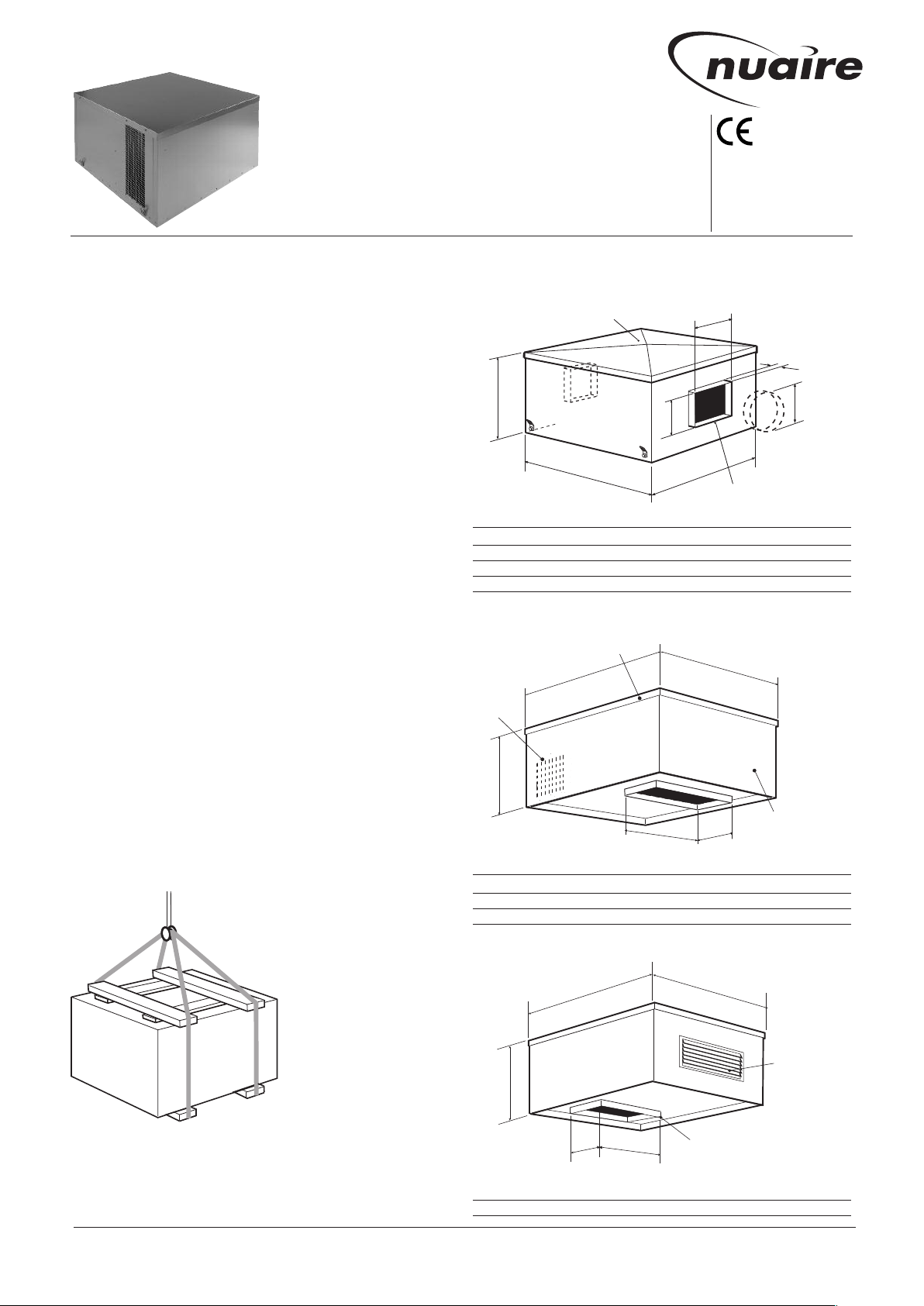
Figure 2. NALTF and NALTRF-1 Units Dimensions
Unit ABCD dia E F
NALTF9-10, NALTRF9-10 974 974 622 400 -NALTF11-12, NALTRF11-12 1233 1233 701 500 -NALTF13-17, NALTRF13-17 1430 1635 796 630 -NALTF18-24, NALTRF18-24 2030 2313 1183 - 1200 700
Figure 3. NALTRF Bottom Inlet Units Dimensions
1.0 Handling
Always handle the units carefully to avoid damage and
distortion. Eyebolts are provided on some units for lifting.
If mechanical aids are used to lift the unit, spreaders should
be employed and positioned so as
to prevent the slings, webbing etc.
making contact with the
casing.
Correctly position slings
to avoid twisting of the
unit case and observe
the centre of gravity
before the final lift is
made. Note: the weight
Figure 1. Lifting unit with slings
via spreaders.
Nuaire: A Trading Division of Polypipe Limited Western Industrial Estate Caerphilly United Kingdom CF83 1NA
T: 029 2088 5911 F: 029 2088 7033 E: [email protected] W: www.nuaire.co.uk
of the unit from the
rating plate.
Spigot
Unit ABC E F
NALTRF9 to NALTRF10 974 974 622 457 229
NALTRF11 to NALTRF12 1233 1233 701 762 304
NALTRF13 to NALTRF17 1430 1635 796 889 381
Figure 4. NALTRF Larger Bottom/End Inlet Units Dimensions
Rect Spigot
Unit ABCE F
NALTRF18 to NALTRF24 2030 2313 1183 1200 700
1
15. 05. 17. Leaflet Number 671269
Page 2
NALTF/TRF Roof and Plantroom Twinfans
680 700 Spigot 640
50mm Spigot
1
2030
1183
1550 min
Curb
1850 max
165 louvre
1200 Spigot
2313
700 Spigot
210
1200 Spigot
2140 max
150
Curb
3.0 Installation
The installation must be carried out by competent
personnel in accordance with the appropriate authority and
conforming to all statutory and governing regulations.
Units must not be installed at an angle over 5ofrom the
horizontal (to ensure the backdraught shutters operate
satisfactorily). Units must be installed with the access panel
on top, never up-side-down.
Units should always be positioned with sufficient space
to allow removal of the access covers and subsequent
removal of fan and motor assemblies etc.
Ductwork connections must be airtight to prevent loss of
performance.
The method of mounting used is the total responsibility of
the installer. The lower edge of the casing has an internal
skirt allowing the unit to be located on an upstand or
prefabricated curb if desired. The units must be securely
screw fixed to the upstand/curb to prevent vibration and/or
wind damage.
It is the installers responsibility to drill the case to provide
access for the electrical cables. Care should be taken not to
damage internal components and the cable entry must be
properly sealed. NOTE: on bottom inlet units the electrical
cabling may be routed up through the bottom inlet spigot.
Testing after Installation
Ensure that the Fan unit and any specified controls are
fitted securely according to the instructions.
Switch on the mains supply. Push the test button to run
each fan and check that they run satisfactorily.
If a switched live signal is used, activate this signal and
check that the fan runs. De-activate the switched live signal
and check the run-on-time; adjust if necessary.
Adjust the maximum and minimum airflow (if required) by
following the commissioning procedures.
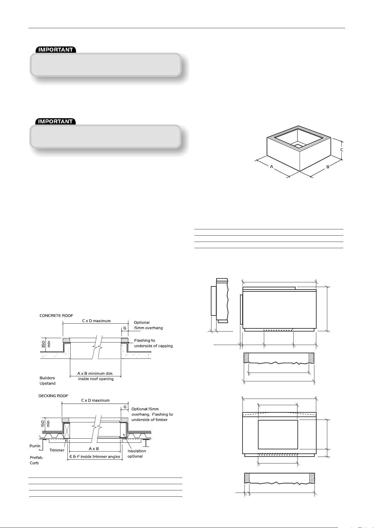
Prefabricated Curb
CODES: NALPFC (typical)
Manufactured in
aluminium alloy these
curbs will reduce design
work and guarantee correct
unit mounting when on site.
Note: Upper faces of curb are fitted with robust sealing
strip.
Prefabricated curb dimensions
Unit Prefab
Code Curb Code AB C
NALTF 9-10 NALPFC 4B 917 917 250
NALTF 11-12 NALPFC 5B 1173 1173 250
NALTF 13-17 NALPFC 6B 1374 1580 250
Figure 6.
Upstand Details
Details of roof opening dimensions etc required and basic
construction of a builders upstand etc are shown below for
typical concrete and decking roof installations.
Roof Opening Dimensions
Figure 5.
Typical Roof Upstand for NALTF 18-24
Figure 7.
Unit Code Prefab Code ABCDEFG
NALTF 9-10 NALPFC 4B 767 767 947 947 837 837 75
NALTF 11-12 NALPFC 5B 973 973 1203 1203 1064 1064 100
NALTF 13-17 NALPFC 6B 1169 1375 1399 1605 1268 1471 100
Note: Prefabricated curbs can be used to support internal or external units.
2
15. 05. 17. Leaflet Number 671269
Page 3
NALTF/TRF Roof and Plantroom Twinfans
400V 3 ph 50Hz Supply
L
L
N
L3
L2
L1
N
FAN UNIT
Fan live applies to
Direct Drive fans only
(Link to be left in)
Fault indicating
voltage free
contacts
Note: relay is
energised if no
fault is present
i.e. COM - N O
is connected if
there is no fault
N O
N C
COM
SL
230V Switched live signal.
Remove L/SL link when using
Switched live overrun
adjustment
NAL-RFI Remote fan
indicator (supplied)
4.0 Electrical Details
Isolation - Before commencing work make sure
that the unit, and any control are
electrically isolated from the mains supply.
Run currents etc.
400V 3 Phase 50Hz
Unit Code Speed Power f lc sc Weight
NALTF/TRF 9 1225 0.75 2.1 9.5 84.4
NALTF/TRF 10 1400 1.1 2.9 13.0 90.4
NALTF/TRF 11 1085 1.5 3.7 8.5 125
NALTF/TRF 12 1225 2.2 5.4 27.0 134
NALTF/TRF 13 1040 2.2 5.4 27.0 168.7
NALTF/TRF 14 1040 4.0 10.0 60.0 193.6
NALTF/TRF 15 1260 3.0 6.9 38.0 174.6
NALTF/TRF 16 1260 5.5 12.0 75.0 231.6
NALTF/TRF 17 1440 5.5 12.0 75.0 231.6
NALTF/TRF 18 700 5.5 12.0 75.0 730
NALTF/TRF 19 800 4.0 10.0 60.0 716
NALTF/TRF 20 800 11.0 23.0 154.0 794
NALTF/TRF 21 1000 5.5 12.0 75.0 730
NALTF/TRF 22 1000 11.0 23.0 154.0 794
NALTF/TRF 23 1100 11.0 23.0 154.0 794
NALTF/TRF 24 1200 11.0 23.0 154.0 794
NOTES:
Because the run and start currents depend upon the duty
and associated ductwork of an individual unit, the values
quoted in the table are nominal.
Run currents will be exceeded if the unit is operated with
its cover removed. The unit must NOT run for more than
2 minutes in this condition.
rpm
(kW)
(amps) (amps) kg
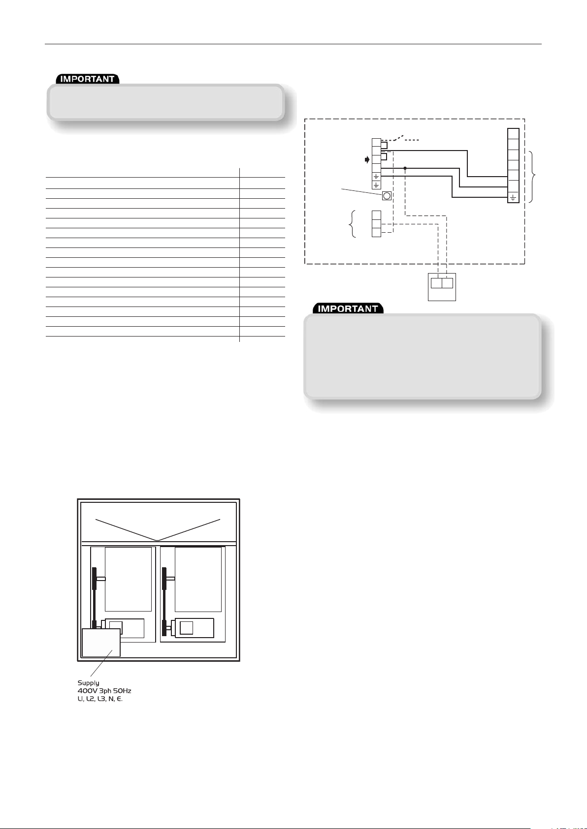
Electrical Installation Basic Layout
Figure 8. Basic internal layout.
Electrical Wiring
Figure 9.
Basic fan wiring diagram for
NALTRF 9-15 and NALTF 9-15 only
The fan will only operate when a 230V mains signal is
present at the SL terminal.
When the SL signal is switched off the fan will continuue to
run for a preset period (1-60 minutes). Adjust the overrun
time at the pot marked ‘-SL RUNON’.
Ensure the local isolator (by others) also isolates
the switched live.
Controls for NALTF/NALTRF 9-15
The NALTF/NALTRF 9-15 fan units incorporate an integral
auto-changeover controller which provides 12 hour duty
share operation and automatic selection of the standby fan
should the duty fan fail.
Fault indication to an external device is provided via volt free
contacts of a relay.
Note: the relay is energised when no fault is present.
Note: It is the responsibility of the installer to provide a
suitable switchable local isolator for maintenance purposes
etc.
NALTF/NALTRF 16-24 Inclusive
These fan units are supplied without any controls fitted.
The electrical power is connected directly to the motor.
Note that the motors are 5.5kW or higher and STAR-DELTA
starting or a Soft Starter should be used in the motor control
panel (by others).
3
15. 05. 17. Leaflet Number 671269
Page 4
NALTF/TRF Roof and Plantroom Twinfans
Changing a Drive Belt
Isolation - Before commencing work make sure
that the unit, and any control are
electrically isolated from the mains supply.
5.0 Maintenance - Fan unit
Maintenance Intervals
The first maintenance should be carried out three months
after commissioning and thereafter at twelve monthly
intervals. These intervals may need to be shortened if the
unit is operating in adverse environmental conditions, or in
heavily polluted air. Access to the unit internals is gained by
removing the top cover(s).
Motors
Brush away any dust or dirt from the motor housings and
ensure that the motor vents are unblocked.
Bearings
Lubrication is unnecessary as the motors are fitted with
sealed for life bearings.
Impellers
Remove any dust and check that the impellers are securely
fixed to the motor shafts. Take care not to disturb any
balance weights fitted. Check sealed for life bearings for
excessive wear.
To replace a belt, remove the two bolts from the motor
mounting furthest from the fan and slacken the remaining
two bolts. Lift the motor plate and remove the belt. Replacing
the belt is the reverse of this procedure.
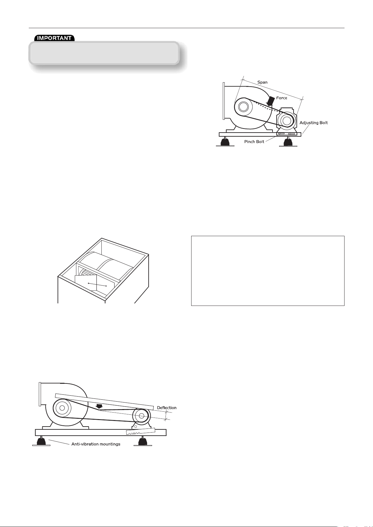
Figure 12. Adjusting the Drive Belts (larger units).
Adjusting Drive Belt Tension (larger units)
All belt drive units incorporate belt tensioning devices.
To adjust the belt tension, slacken the pinch bolt on the sides
of the motor plate. Turn the adjusting bolt clockwise to
tighten the belt and counter clockwise to loosen it.
The drive should be tensioned until a slight bow appears in
the slack side of the ‘V’ belt when running under load.
To check for correct tension, proceed as follows.
1. Measure the span length (See figure 12).
2. At the centre of the span, apply a force at right
angles to the belt sufficient to deflect one belt
16mm for every metre of span length
(see figure 12). The force required to deflect
the ‘V’ belt should be from 0.5kg to 0.8kg.
3. Tighten the pinch bolts.
Figure 10. Shutter detail.
Shutter Assembly
Remove any dust and check that the shutters operate freely
and that they seal the appropriate fan outlet effectively.
Anti Vibration Motor Plate Mountings
Each motor plate is supported on ten individual resilient
mountings. Check that all the mountings are secure and in
good condition. (See figure 11).
Figure 11. Adjusting the Drive Belts (smaller units).
Adjusting Drive Belt Tension (smaller units).
To check the correct tension of a drive belt, apply a force at
right angles to the centre of the belt span sufficient to deflect
the belt 16mm for every metre of span length (see figure 11).
The force required to deflect the ‘V’ belt should be from
0.5kg to 0.8kg.
General Cleaning and Inspection
Clean and inspect the exterior of the fan unit and associated
controls etc. Remove the access panel from the fan unit.
Inspect and, if necessary, clean the fan and motor assemblies
and the interior of the case. If the unit is heavily soiled it
may be more convenient to remove the fan/motor
assemblies. If NuAire controls and or remote indicators are
fitted, remove the covers and carefully clean out the
interiors as necessary. Check for damage. Check security of
components. Refit the access covers.
General
1. Check that all fixings are tight.
2. Check sealing strips around the fan outlets are
tight up against the bulkhead.
3. Check that duct connections are not leaking.
4
15. 05. 17. Leaflet Number 671269
Page 5

NALTF/TRF Roof and Plantroom Twinfans
6.0 Replacement of Parts
Drive belts are the only servicable items on these fan units.
With time and fair wear and tear it may be necessary to
replace fan assemblies or motors - consult the fan rating
plate detail when ordering.
Note: Isolate the Electrical Supply
Remove the top access panel. Disconnect the wiring to the
motor assembly. Remove the old unit. Replace the fan/
motor assembly. Re-connect the supply to the motor. Check
for correct rotation and operation and replace the top
access panel.
Spare Parts
When ordering spares please quote the serial number of the
unit. This number will be found on the identification plate
attached to the unit mounting frame. Please give a full
description of the part required.
7.0 Warranty
The unit has a one year warranty. The warranty starts
from the date of delivery and covers faulty materials or
workmanship and includes parts and labour. The labour
element is subject to full, free and safe access to the
equipment as recommended by the CDM regulations.
This warranty is void if the equipment is modified without
authorisation, is incorrectly applied, misused,
disassembled, or not installed, commissioned and
maintained in accordance with the details contained in this
manual and general good practice.
The product warranty applies to the UK mainland and in
accordance with Clause 14 of our Conditions of Sale.
Customers purchasing from outside of the UK should
contact Nuaire International Sales office for further details.
8.0 After Sales Enquiries
For technical assistance or further product
information, including spare parts and replacement
components, please contact the After Sales Department.
Telephone 02920 858 400
5
15. 05. 17. Leaflet Number 671269
Page 6
DECLARATION OF INCORPORATION AND INFORMATION FOR SAFE INSTALLATION,
OPERATION AND MAINTENANCE
We decla re that t he machinery nam ed below i s in te nd ed to be
ass em bl ed w ith ot he r co mp on en ts t o c on st itut e a sy ste m of
Signature of manufacture representatives:
Name: Position: Date:
machin ery . The m ach ine ry shal l not be put into ser vic e unt il the
system has been declared to be in conformity with the provisions of the
1) C. Biggs Technical Director 20. 07. 07
EC Machinery Directive.
Designation of machinery: BELT DRIVE TWINFAN
2) A. Jones Manufacturing Director 20. 07. 07
Machinery Types: NALTF, NALTRF
Relevant EC Council Directives: 2006/42/EC (Machinery Directive)
Applied Harmonised Standards: BS EN ISO 12100-1, BS EN ISO 12100-2,
EN294, EN60204-1, BS EN ISO 9001
Applied National Standards: BS848 Parts One, Two and Five
Note: All standards used were current and valid at the date of signature.
INFORMATION FOR SAFE INSTALLATION, OPERATION AND MAINTENANCE
OF NUAIRE VENTILATION EQUIPMENT
To comply with EC Council Directives 2006/42/EC Machinery Directive and
2014/30/EU (EMC).
T
o
be
r
ea
d in
con
jun
ction
with
th
e releva
nt
Pro
d
u
ct
D
o
cu
m
en
t
at
io
n
(s
ee
1.0
1.1
2
2.1
2.2
2.3
3
3.1
3.2
3.3
4.0
4.1
4.2
4.3
G
ENERA
L
T
he equip
me
nt ref
erred
to
in
this
Decla
rat
io
n
of
In
c
or
p
or
Nua
ire
to
b
e a
ssem
b
led
in
to
a
v
en
tila
tio
n
s
ys
a
dd
itio
na
l co
mp
o
n
en
ility o
f
th
tio
n
T
IO
N SU
f
equip
tio
n re
t. T
his m
n
ce in
str
s a
ra
tia
ta
t
ire.
rn
in
g la
d
hered
t
R
T
A
TIO
e ta
ken
it m
dl
ing the equip
is
p
es mu
t s
to
red
n
d
step
N
A
L
L
nt tha
e.g. o
pe
n
.
lla
tio
n
tin
g b
ra
m
n
d
co
n
n
ts.
must b
e co
e in
sta
ller to
e ma
n
uf
a
a
nd
co
des o
PPL
IE
D WIT
men
t is
sup
quired
f
or the
ay b
e in
the f
uctio
n
.
tin
g p
la
te a
l
d
ata
rela
l d
ata
. An
io
n. If
a
ny item
bels o
r
no
o.
N,
HA
NDL
a
t a
ll
times to
a
y result in
m
en
trib
utio
n
st b
e a
rra
o
n site
p
rio
s
ta
ken
to
IM
IT
S
t the sp
ecif
ra
tio
na
l a
a
ccess
o
ries a
ckets. T
hey a
po
n
en
ts mus
ectio
n
s
p
igo
s. They must
n
s
ctu
f
p
lied
orm o
tta
tin
g
y f
u
tices a
ING
t, ca
wit
n
g
ed
r to
p
re
ied
ir t
ts a
id
ered
en
rers reco
p
ra
H T
sa
ched
to
rther d
is un
A
p
the b
re sho
hin
so
in
ven
o
emp
re sup
re to
t ha
re p
n
ot b
T
he en
t
ire system
resp
o
n
sib
co
mp
lia
n
ce with th
curren
t
legisla
.0
I
NFO
RM
A
E
a
ch item o
the in
fo
rma
equip
m
en
M
a
in
te
na
E
a
ch un
it ha
p
ro
vid
e
s essen
co
d
e a
n
d
electrica
in
the d
o
cumen
co
n
ta
c
t Nua
W
here wa
must b
e a
.0
T
RA
NSPO
C
a
re must b
sho
ck t
o
the un
W
hen
ha
n
tha
t th
e weight d
slin
gs o
r ro
E
quip
men
wea
the
r a
O
PERA
T
IO
I
t is imp
o
rta
a
dhere
d to
o
rien
ta
tio
W
here in
sta
wa
ll mo
un
Other s
ystem co
F
la
n
ges a
d
uct w
ork system
f
sure tha
c
tice.
HE
wit
h a
fe in
f a
t
the equ
clea
re a
t
ND
rev
a
la
the un
a
s n
sta
t in
gres
p
era
tio
era
ture
p
b
e us
ve sep
ro
e use
or s
EQ
sta
Da
o
ata
ta
ST
en
n
uld
lla
its
lie
mm
ce
vid
te
af
et
t
al
l o
e
n
da
U
IP
M
s
e
t
of
lla
ti
on
ta
s
h
o
u
te
ipm
e
n
th
a
t m
r
o
r
m
ch
e
d
to
OR
A
t
d
am
a
o
f t
h
b
e
ta
it
is
c
on
o
t t
o
b
ti
o
n
sh
s
of
c
n
a
l li
m
, a
ir
b
d
w
ith
ed
t
o
a
ra
te
p
e
d
fo
d
t
o
s
a
m
w
h
ich
m
a
y
pu
rp
o
se
s
a
f
th
e
eq
ui
pm
ti
on
s
a
nd
w
E
NT
d
oc
u
m
en
ta
a
n
d
ma
in
t
ee
t a
n
d
/o
r
r
ca
s
ing
.
T
t s
u
ch
a
s
s
a
y
b
e
re
qu
or
e
in
fo
rm
a
t
he
u
n
it
th
G
E
g
e t
o
th
e
e
qu
e i
m
pe
lle
r
be
ke
n
w
it
h
co
s
id
er
ed
.
Li
ea
r
on
t
he
c
o
ul
d b
e
p
ro
on
ta
m
in
a
nt
its
f
or
t
he
e
or
n
e c
o
nt
am
t
he
s
p
ec
ifi
su
p
po
rt
t
he
ro
v
is
io
n
fo
r
th
e
pu
r
po
up
po
r
t t
h
e d
2
tio
n
i
s s
u
pp
y
o
r m
a
y
n
ot
nd
i
t i
s t
h
e
e
n
t i
s
in
st
al
it
h
d
ue
r
eg
ti
on
w
h
ic
h
en
In
he
er
e
rn
te
qu
ed
s
pr
an
c
e
of
th
st
al
la
tio
n
a
r
at
in
g
pl
at
ia
l n
um
b
e
r,
ir
ed
w
il
l b
e
fo
ti
on
is
r
eq
u
ir
in
st
ru
ct
io
n
ip
m
en
t.
N
o
in
g
a
ff
ec
te
d.
e
rs
a
nd
e
d
ft
in
g
ge
a
r s
as
in
g
.
ct
ed
f
ro
m
t
s.
ip
m
e
nt
a
re
i
na
n
ts
a
nd
e
q
uip
m
e
nt
e
qu
ip
m
e
nt
o
r
su
p
po
rt
.
e o
f
jo
in
in
g
u
ct
w
or
k
.
.1
)
li
ed
in
c
led
ar
d
ov
e
nd
e
un
u
nd
ed
s g
te
t
ge
s
u
ch
he
u
n
e
g.
nl
y.
to
5.0 INSTALLATION REQUIREMENTS
In addition to the particular requirements given for the individual product, the
following general requirements should be noted.
5.1 Where access to any part of equipment which moves, or can become electrically
b
y
lu
de
i
n
to
id
e
s
it
,
iv
e
n
ha
t
an
d
a
s
it
live are not prevented by the equipment panels or by fixed installation detail
(eg ducting), then guarding to the appropriate standard must be fitted.
5.2 The electrical installation of the equipment must comply with the requirements
of the relevant local electrical safety regulations.
5.3 For EMC all control and sensor cables should not be placed within 50mm or on
the same metal cable tray as 230V switched live, lighting or power cables and
any cables not intended for use with this product.
6.0 COMMISSIONING REQUIREMENTS
6.1 General pre-commissioning checks relevant to safe operation consist of the
following:
Ensure that no foreign bodies are present within the fan or casing.
Check electrical safety. e.g. Insulation and earthing.
Check guarding of system.
Check operation of Isolators/Controls.
Check fastenings for security.
6.2 Other commissioning requirements are given in the relevant product documentation.
7.0 OPERATIONAL REQUIREMENTS
7.1 Equipment access panels must be in place at all times during operation of the
unit, and must be secured with the original fastenings.
7.2 If failure of the equipment occurs or is suspected then it should be taken out of
service until a competent person can effect repair or examination. (Note that
certain ranges of equipment are designed to detect and compensate for fan failure).
8.0 MAINTENANCE REQUIREMENTS
8.1 Specific maintenance requirements are given in the relevant product documentation.
8.2 It is important that the correct tools are used for the various tasks required.
8.3 If the access panels are to be removed for any reason the electrical supply to the
unit must be isolated.
8.4 A minium period of two minutes should be allowed after electrical disconnection
before access panels are removed. This will allow the impeller to come to rest.
NB: Care should still be taken however since airflow generated at some
other point in the system can cause the impeller to “windmill” even when
power is not present.
8.5 Care should be taken when removing and storing access panels in windy
conditions.
Technical or commercial considerations may, from time to time, make it necessary to alter the design,
performance and dimensions of equipment and the right is reserved to make such changes without prior notice.
6
15. 05. 17. Leaflet Number 671269
 Loading...