

Page 1

Yellow Box User Manual
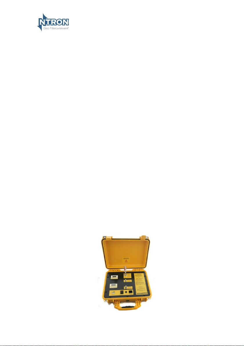
Yellow Box
z
Issue Number:
1.14
Issue Date:
29/01/2018
V.1.1
The
General Short Form User Manual
Portable Oxygen Analyser
Part Number.: 05-674
Page 2
Yellow Box User Manual
Contents
1. Introduction .................................................................................... 3
1.1 SPECIFICATIONS .................................................................. 3
2. Warnings ! ....................................................................................... 4
3. Start up ............................................................................................ 4
4. Operation ......................................................................................... 5
5. Calibration ....................................................................................... 6
MENU 1 – CALIBRATE SENSOR .......................................................... 7
MENU 8 - DIAGNOSTICS .................................................................... 8
The Yellow Box Analyser ................................................................... 9
Frontplate Description ....................................................................... 9
6. Maintenance .................................................................................. 10
Page 3
Yellow Box User Manual
V.1.1
Issue:
1.14
Page 3
1. INTRODUCTION
The Yellow Box Portable Oxygen Analyser is based on the Microx range of
Oxygen Analysers and incorporates two selectable Microx Analysers which
are application dependant to the end users requirements.
Typical measurement ranges are 0-25% and 0-1000ppm, and these will be
taken as a basis for the instructions that follow in this manual. For Yellow Box
models with different measurement ranges, the same operational principles
apply but calibration gases will differ. (Details available from Ntron when
required)
The Instrument is powered by connection to a main AC power supply as given
in the specification table below but is also available with an optional internal
Battery offering remote operation where no mains power outlet is available
and power back-up in case of a mains power failure. This option, if required,
must be specified at time of order.
The Yellow Box contains a flow indicator and flow adjustment to enable the
correct amount of sample gas to be presented to the internal Zirconia Oxygen
Sensors.
The Yellow Box is presented in a robust carry-case with Lid which provides
protection during transportation and use.
1.1 Specifications
Supply
Mains Input
Voltage
85-264VAC ; 47-63Hz; 0.1-0.15A
Battery Option:
Backup battery @ 12VDC , 2.3AH
Sensor
Type:
ppm and % Zirconia Oxide
Life:
5 years (Depending on Air exposure and other
gases)
Typical Range
%
0.1-25 Oxygen; Accuracy 2% of FSD
ppm
1-1000 Oxygen; Accuracy 2% of FSD
Sample Gas Input/Output
Pressure:
</= 2 Barg
Flow:
300-500 cc/minute (Typically 250cc/minute)
Fuses
Main Fuse
500mA anti-surge front panel fuse for input
protection.
Additional Features (microx analysers)
Page 4

Yellow Box User Manual
V.1.1
Issue:
1.14
Page 4
Display:
4 Digit, 7 Segment Display.
Keypad:
4-Button Keypad
Weight:
Typically 8Kg but dependant on model type.
Operating Temp.
+5 to +45 Degrees Centigrade
2. WARNINGS !
Over pressure at the sample gas input to the Yellow Box can damage the
internal Sensors.
Moisture or other liquid with the sample gas stream can damage the
internal Sensors particularly if applied when the internal Sensors are in
their un-powered/un-heated state.
3. START UP
.
Switch-on the Yellow Box by operating the %-On/Off-ppm 3 –position switch
on the front plate of the Yellow Box.
(Select % or ppm )
(For units with optional internal Battery, ensure that the battery is charged
sufficiently for operation or that the yellow Box is connected to the mains
electrical supply)
Choose the Microx module for the correct range of sample gas to be
measured.
When power is then first applied to the Microx module (% or ppm) an
initialisation procedure is performed as follows:
• All the display segments are displayed
• The software version number is displayed
• The company name is displayed
• The sensor type is displayed
• The display then shows the gas level.
The module is now operational
Page 5

Yellow Box User Manual
V.1.1
Issue:
1.14
Page 5
4. OPERATION
Note: A series of instruction labels are affixed to the front plate of the
Yellow Box and these can be followed for quick reference. Please see
the photograph of the front plate following the written instructions
below.
1. When the Yellow Box is first switched-on, do not use it for at least 15
minutes to allow the internal Zirconia Sensors to reach correct
operating temperature.
2. Connect a Rotameter (flowmeter) to the sample gas exhaust outlet of
the Yellow Box.
3. Ensure that at this time, the gas flow regulator valve on the Yellow
Box front plate is closed.
4. Measure or otherwise confirm the pressure of the sample gas to be
supplied to the Yellow Box before connection to the Yellow Box. If it
is in excess of 2 Barg, then the pressure must be reduced using
external components. (e.g. Pressure relief valve to line. Relief to
ambient air may result in sample contamination)
5. Connect the sample gas source to the Yellow Box Sample gas input
connection. This should be less than or equal to 2Barg.
6. Open the gas flow regulator valve and set the flow rate to between
300 and 500 cc per minute.(Visible on the Rotameter connected to
the sample gas outlet) At the same time the gas flow should be
indicated to be within the green section of the in-built flow indicator
on the Yellow Box frontplate.
7. Wait until all air is purged from the sample line and a stable reading
is obtained. For ppm measurement, this will take much longer
especially if the sample pipework within the yellow Box has been
exposed to ambient air.
8. Measurements can now be observed.
Page 6

Yellow Box User Manual
V.1.1
Issue:
1.14
Page 6
5. CALIBRATION
This is done by using the Menu functions on the Microx modules.
A Zero point calibration is not normally required after the initial setting when
manufactured, so calibration consists of a Span calibration for both the ppm
and % Microx modules.
Normal calibration gas used:
Certified gas 100ppm for the ppm Microx module.
Certified gas 20.9% for the % Microx module.
These gases should be applied individually after selecting the appropriate
Microx module to be calibrated. (It may be better to first calibrate the ppm
Microx module )
For a calibration to be performed, it is necessary to use the Menu system of
the Microx module. here are a range of Menus visible to the user but only
small number are required or should be entered by the user of the yellow Box.
Menu
option
Function
E:1
Calibrate Sensor
E:2
Analogue output FSD Not used/Do Not Use
E:3
Set 4 mA Not used/Do Not Use
E:4
Set 20 mA Not used/Do Not Use
E:5
Sensor simulation Not used/Do Not Use
E:6
Set sensor type Not used/Do Not Use
E:7
Not used/Do Not Use
E:8
Diagnostics Observation only.
E:9
Set Sensor type Not used/Do Not Use
Page 7

Yellow Box User Manual
V.1.1
Issue:
1.14
Page 7
1. Follow the start up procedures as detailed previously.
2. If required, fit the Rotameter to the sample outlet of the Yellow Box.
3. Ensure the gas pressure from the calibration gas source is within the
2 Barg pressure rating.
4. The required sample gas should be connected to the Yellow Box
sample input and allowed to flow sufficiently to purge the system.
5. When the reading on the Microx module is steady, compare it to the
value of the calibration gas. If correction is required, follow the
calibration procedure which follows.
Menu 1 – Calibrate sensor
• Press the MENU button to open the menu system.
• Using the NEXT and PREVIOUS buttons select menu option:
E:1
• Press ENTER.
• Apply a known concentration of gas (applicable to sensor type)
at a flow rate of between 100 to 500 ml/m. Allow time for the
sensor to respond. (see diagram on page 8)
• Using the INC and DEC buttons set the reading to that of the
calibration gas level.
• Press ENTER to span the sensor, ‘– – – –‘will be displayed to
confirm the sensor span has been performed.
Note: Pressing the MENU button rather than the ENTER
button exits the span feature without performing the
calibration.
Wait until the reading is stable, if not press the ENTER
button to span the sensor.
• Press the MENU button to close the menu system.
Note: The sensor span setting will be displayed ( as a
percentage value) on exit while the MENU key is pressed.
Note that this value is a percentage of the initial calibration
value .
• Turn off and disconnect the calibration gas.
Repeat the procedure for the second Microx module.
Page 8

Yellow Box User Manual
V.1.1
Issue:
1.14
Page 8
Microx module
The keypad has the following functionality:
Button
Function
Alternate Function
A
Menu Open/Close
B
Enter
C
Next (Increment)
D
Previous (Decrement)
Menu 8 - Diagnostics
This feature is a view-only feature. No configuration changes are possible
from within this menu.
• Press the MENU button to open the menu system.
• Using the NEXT and PREVIOUS buttons select menu option:
E:8
• Press ENTER.
• The display will alternate between the current value and
diagnostic code E:8x: where x is:
0 Sensor signal, A to D counts low ppm range.
1 Sensor signal, A to D counts high ppm range.
2 Sensor signal, A to D counts %vol range.
3 Firmware version.
• The diagnostic code can be selected by pressing the UP button.
• Press MENU to return the instrument to its standard mode of
operation.
20.9
Page 9

Yellow Box User Manual
V.1.1
Issue:
1.14
Page 9
The Yellow Box Analyser
Frontplate Description
*Battery Charge
Indicator
On/Off %/ppm
Selector Switch
Flow control/adjust
Mains power connection
Fuse
Sample gas
exhaust
Sample gas
input
Sample Gas Flowmeter
Brief Instructions:
1. Power up the unit by selecting % or PPM with the 3 position switch.
2. Close the flow adjust valve by turning it fully clockwise
3. Turn the flow indicator to its vertical position.
4. Connect a gas sample via the sample inlet port
5. Gradually open the flow adjust valve to achieve a flow in the green sector of
the flow indicator.
6. Allow the oxygen reading to stabilise and thereafter a reading can be taken.
*Models with optional internal Battery only.
✓
Page 10

Yellow Box User Manual
V.1.1
Issue:
1.14
Page 10
6. MAINTENANCE
Ensure that the Yellow Box faceplate is kept clean at all times.
Do not use chemical or abrasive cleaners on the Yellow Box case or
frontplate.
Perform annual calibration or as required.
When not in use, cover or plug the sample gas inlet and outlet ports of the
yellow box to minimise air intake and contaminants/ particulates.
Keep the cover of the Yellow Box closed when not in use.
The internal Sensors should provide a long life of operation but will require
replacement as some point. Contact the manufacturer when this is required.
Sensor replacement required may be indicated by a difficulty to calibrate the
Microx modules.
Note: some gases may be damaging to the Zirconia Sensor such as
Halogens or organic vapours. When the yellow Box is not under power,
water, condensed humidity and gases such as H2S and SOx should not be
allowed to flow into the yellow Box.
Optional Battery Unit.
The optional internal battery should provide a long life of operation but will
require replacement at some point. Contact the manufacturer when this is
required.
This will be indicated when the operating period of the Battery reduces
dramatically.
Page 11

Yellow Box User Manual
V.1.1
Issue:
1.14
Page 11
Mullaghboy Industrial Park
Navan, Co. Meath, Ireland
Phone: 00-353-46-9071333 • FAX: 00-353-46-9071331
E-Mail: info@ntron.com
Web: www.ntron.com
 Loading...