

Page 1

7014 Series
Industrial
Gigabit Ethernet Switch
User Manual &
Installation
Guide
6/28/2007 page 1 of 145
Page 2

7014TX, 7014FX2, and 7014FXE2 Industrial Gigabit Ethernet Switch Installation Guide........................................ 7
Safety Warnings........................................................................................................................................................... 8
Installation.................................................................................................................................................................. 10
Connecting the Unit ................................................................................................................................................... 14
Overview of Advanced Features................................................................................................................................ 17
Mode of Operation..................................................................................................................................................................17
Port Security............................................................................................................................................................................17
Port Mirroring .........................................................................................................................................................................17
Port Trunking..........................................................................................................................................................................17
Priority Tagging (QoS)............................................................................................................................................................18
Virtual LAN............................................................................................................................................................................18
Rapid Spanning Tree Protocol ................................................................................................................................................18
SNMP Traps............................................................................................................................................................................19
IGMP Snooping ......................................................................................................................................................................19
N-Ring.....................................................................................................................................................................................19
Web Software Configuration ..................................................................................................................................... 21
Web Management ...................................................................................................................................................................21
Web Management - Home ......................................................................................................................................................22
Administration – System.........................................................................................................................................................24
Administration – SNMP..........................................................................................................................................................25
Administration – Gigabit Ports................................................................................................................................................26
Ports – Configuration..............................................................................................................................................................27
Ports – Security.......................................................................................................................................................................29
Ports – Intrusion Log...............................................................................................................................................................31
Ports – Mirroring.....................................................................................................................................................................32
Ports – Trunking......................................................................................................................................................................33
Statistics – Port Statistics ........................................................................................................................................................35
Statistics – Port Utilization......................................................................................................................................................36
VLAN – Ingress Filter.............................................................................................................................................................37
VLAN – Port Based ................................................................................................................................................................39
Bridging – Aging Time...........................................................................................................................................................42
Bridging – Unicast Addresses.................................................................................................................................................43
Bridging – Multicast Addresses..............................................................................................................................................45
RSTP – RSTP Configuration ..................................................................................................................................................47
IGMP – Configuration ............................................................................................................................................................50
IGMP – Show Group and Show Router..................................................................................................................................53
IGMP – RFilter .......................................................................................................................................................................54
N-View – Configuration..........................................................................................................................................................56
N-View – Ports........................................................................................................................................................................57
N-Ring - Configuration...........................................................................................................................................................59
N-Ring – Status.......................................................................................................................................................................63
Event Log – Log Statistics......................................................................................................................................................67
Event Log – Show Events.......................................................................................................................................................68
Firmware/Config - TFTP ........................................................................................................................................................69
Firmware/Config - FTP...........................................................................................................................................................70
Support – Web Site and E-mail...............................................................................................................................................71
BPCL – Broadcast Packet Count Limit Configuration ...........................................................................................................72
User Mgmt – Adding Users ....................................................................................................................................................74
User Mgmt – Removing Users................................................................................................................................................75
LogicalView............................................................................................................................................................................76
Configuration – Save or Reset.................................................................................................................................................77
Help – Administration.............................................................................................................................................................79
Help – Ports.............................................................................................................................................................................80
Help – Statistics.......................................................................................................................................................................81
Help – VLAN..........................................................................................................................................................................82
Help – BPCL...........................................................................................................................................................................83
Help – IGMP...........................................................................................................................................................................84
Help – Bridging.......................................................................................................................................................................85
Help – RSTP ...........................................................................................................................................................................86
6/28/2007 page 2 of 145
Page 3

Help – Event Log....................................................................................................................................................................87
Help – Firmware/Config .........................................................................................................................................................88
Help – Logical View...............................................................................................................................................................89
Help – User Mgmt...................................................................................................................................................................90
Help – N-View........................................................................................................................................................................91
Help – N-Ring.........................................................................................................................................................................92
Help – Others ..........................................................................................................................................................................93
CLI Commands..........................................................................................................................................................94
Clear........................................................................................................................................................................................94
“?” (HELP)..............................................................................................................................................................................94
Top..........................................................................................................................................................................................95
Up............................................................................................................................................................................................95
Logout.....................................................................................................................................................................................95
History.....................................................................................................................................................................................95
“!”............................................................................................................................................................................................96
“$”...........................................................................................................................................................................................97
Whoami...................................................................................................................................................................................97
Ping .........................................................................................................................................................................................97
System Configuration Commands ............................................................................................................................. 98
Set Mode IP config..................................................................................................................................................................98
Set IP/Subnet/Gateway Addresses of the system....................................................................................................................98
Get IP Address of the system..................................................................................................................................................98
Set System Name ....................................................................................................................................................................98
Get System Name....................................................................................................................................................................98
Get Gateway Address of the System.......................................................................................................................................99
Get Mac Address of the System..............................................................................................................................................99
Get Netmask of the System.....................................................................................................................................................99
Get System Contact.................................................................................................................................................................99
Set System Contact .................................................................................................................................................................99
Get System Location...............................................................................................................................................................99
Set System Location..............................................................................................................................................................100
Get System Uptime ...............................................................................................................................................................100
Get Number of Ports present in the System ..........................................................................................................................100
Set IP Address of the SNMP Manager..................................................................................................................................100
Set SNMP Get Community name .........................................................................................................................................100
Set SNMP Set Community name..........................................................................................................................................101
Set SNMP Trap Community name........................................................................................................................................101
Show all configuration parameters........................................................................................................................................101
Show all configuration parameters related to SNMP manager .............................................................................................102
System Restart.......................................................................................................................................................................102
User Management Commands ................................................................................................................................. 103
Show System Users...............................................................................................................................................................103
Add a System User................................................................................................................................................................103
Modify a User’s Access Permissions....................................................................................................................................103
Modify a User’s Password ....................................................................................................................................................103
Remove a System User .........................................................................................................................................................104
Image Loader Commands ........................................................................................................................................104
Download Image through COM port ....................................................................................................................................104
TFTP Commands ..................................................................................................................................................... 104
Set the TFTP configuration parameter..................................................................................................................................104
Show TFTP configuration parameters...................................................................................................................................104
Download file from TFTP server..........................................................................................................................................105
FTP Commands........................................................................................................................................................ 105
Set Username ........................................................................................................................................................................105
Set Password .........................................................................................................................................................................105
Set IP Address of FTP server................................................................................................................................................105
Set Name of the Remote File ................................................................................................................................................106
Display FTP related configuration parameters......................................................................................................................106
Perform the configuration file transfer action .......................................................................................................................106
Perform the image file transfer action...................................................................................................................................106
6/28/2007 page 3 of 145
Page 4

Port Manager Commands......................................................................................................................................... 107
Get the link state of a given port ...........................................................................................................................................107
Get admin status of the port ..................................................................................................................................................107
Set admin status of a port......................................................................................................................................................107
Show port statistics ...............................................................................................................................................................108
Get total number of good frames received............................................................................................................................108
Get port speed .......................................................................................................................................................................108
Set Port Speed.......................................................................................................................................................................109
Get the port duplex mode......................................................................................................................................................109
Set the port duplex mode.......................................................................................................................................................109
Set the Lockstate of a given port...........................................................................................................................................109
Get Lock State.......................................................................................................................................................................110
Get Auto-negotiation State....................................................................................................................................................110
Set Auto-negotiation State ....................................................................................................................................................110
Set Priority State ...................................................................................................................................................................110
Set Flow Control...................................................................................................................................................................111
Set Name...............................................................................................................................................................................111
Set PVID ...............................................................................................................................................................................111
Set Backpressure...................................................................................................................................................................111
Set Intruderstate ....................................................................................................................................................................111
Set Priority Level ..................................................................................................................................................................112
Show Configuration ..............................................................................................................................................................112
Show Intruders......................................................................................................................................................................112
Show Link Utilization...........................................................................................................................................................112
Get Flow Control...................................................................................................................................................................112
Get Name ..............................................................................................................................................................................112
Get State Of Priority.............................................................................................................................................................113
Get Intruder State..................................................................................................................................................................113
Get Priority Level..................................................................................................................................................................113
Get STP Status ......................................................................................................................................................................113
Get Back Pressure .................................................................................................................................................................113
Get PVID...............................................................................................................................................................................113
Clear Counters.......................................................................................................................................................................114
Clear Intruder Log.................................................................................................................................................................114
Trunk related commands.......................................................................................................................................... 114
Enable or disableTrunking....................................................................................................................................................114
Modify Trunk........................................................................................................................................................................114
Create Trunk..........................................................................................................................................................................115
Delete Trunk..........................................................................................................................................................................115
Show Trunk Information.......................................................................................................................................................115
Mirroring related commands.................................................................................................................................... 116
Set Mirror config...................................................................................................................................................................116
Enable or Disable Port Mirroring..........................................................................................................................................116
Show Mirror config...............................................................................................................................................................116
VLAN Related Commands ......................................................................................................................................117
Add VLAN Entry..................................................................................................................................................................117
Show List of Configured VLANs .........................................................................................................................................117
Display Information of a particular VLAN...........................................................................................................................117
Modify an existing VLAN ....................................................................................................................................................118
Delete VLAN........................................................................................................................................................................118
Set VLAN as management VLAN........................................................................................................................................119
Set VLAN to defaults............................................................................................................................................................119
Set VLAN Ingress Filter .......................................................................................................................................................119
Get VLAN Ingress Filter.......................................................................................................................................................119
Get VLAN info .....................................................................................................................................................................119
Eventlog Related Commands...................................................................................................................................120
Get Eventlog count................................................................................................................................................................120
Get Eventlog level.................................................................................................................................................................120
Get Eventlog size ..................................................................................................................................................................120
Set Eventlog level .................................................................................................................................................................120
6/28/2007 page 4 of 145
Page 5

Set Eventlog size...................................................................................................................................................................120
Show Eventlog events...........................................................................................................................................................121
Bridging Related Commands ................................................................................................................................... 122
Add Multicast MAC Address................................................................................................................................................122
Delete Multicast MAC Address............................................................................................................................................122
Add a Unicast MAC Address................................................................................................................................................122
Delete Unicast MAC Address...............................................................................................................................................122
Display List of Configured Static MAC Addresses ..............................................................................................................123
Set Aging Time.....................................................................................................................................................................123
Display Current Aging Time.................................................................................................................................................123
Display Mac Address by port................................................................................................................................................123
Display port by Mac Address................................................................................................................................................123
Display Mac count ................................................................................................................................................................123
IGMP Related Commands ....................................................................................................................................... 125
Enable IGMP.........................................................................................................................................................................125
Disable IGMP........................................................................................................................................................................125
Show IGMP config ...............................................................................................................................................................125
Show IGMP group ................................................................................................................................................................125
Show IGMP router................................................................................................................................................................126
Set IGMP query mode...........................................................................................................................................................126
Set IGMP router port.............................................................................................................................................................126
Set IGMP router mode ..........................................................................................................................................................126
Show IGMP rfilter mode.......................................................................................................................................................127
Set IGMP rfilter mode...........................................................................................................................................................127
N-Ring Related Commands ..................................................................................................................................... 128
N-Ring get agingtime............................................................................................................................................................128
N-Ring set agingtime ............................................................................................................................................................128
N-Ring get webfault..............................................................................................................................................................128
N-Ring set webfault ..............................................................................................................................................................128
N-Ring get interval................................................................................................................................................................128
N-Ring set interval................................................................................................................................................................129
N-Ring get mode...................................................................................................................................................................129
N-Ring set mode ...................................................................................................................................................................129
N-Ring show status ...............................................................................................................................................................130
N-Ring show switch..............................................................................................................................................................130
N-Ring set keepalive.............................................................................................................................................................131
N-Ring get keepalive.............................................................................................................................................................131
Configuration Related Commands...........................................................................................................................132
Save Configuration................................................................................................................................................................132
Load Default Configuration ..................................................................................................................................................132
Configuration Upload............................................................................................................................................................132
Server-IpAddress .................................................................................................................. 132
File-Name ............................................................................................................................. 132
Configuration Download.......................................................................................................................................................132
Server-IpAddress .................................................................................................................. 132
File-Name ............................................................................................................................. 132
Rapid Spanning Tree Protocol Related Commands................................................................................................. 133
Set RSTP Admin Edge..........................................................................................................................................................133
Get RSTP Admin Edge.........................................................................................................................................................133
Set RSTP Auto Edge.............................................................................................................................................................133
Get RSTP Auto Edge ............................................................................................................................................................133
Set RSTP Bridge Admin Status.............................................................................................................................................134
Get RSTP Bridge Admin Status............................................................................................................................................134
Set RSTP Bridge Forward Delay ..........................................................................................................................................134
Get RSTP Bridge Forward Delay..........................................................................................................................................134
Set RSTP Bridge Hello Time................................................................................................................................................135
Get RSTP Bridge Hello Time ...............................................................................................................................................135
Set RSTP Bridge Max Age ...................................................................................................................................................135
Get RSTP Bridge Max Age...................................................................................................................................................135
Set RSTP Bridge Priority......................................................................................................................................................136
6/28/2007 page 5 of 145
Page 6

Get RSTP Bridge Priority .....................................................................................................................................................136
Set RSTP Port Path Cost.......................................................................................................................................................136
Get RSTP Port Path Cost ......................................................................................................................................................136
Set RSTP Port Priority ..........................................................................................................................................................137
Get RSTP Port Priority..........................................................................................................................................................137
Broadcast Packet Count Limit Commands ..............................................................................................................138
Get the Broadcast Packet Count Limit for one port ..............................................................................................................138
Get the Broadcast Packet Count Limit for all ports...............................................................................................................138
Set the Broadcast Packet Count Limit...................................................................................................................................138
VLAN Configuration Examples .............................................................................................................................. 139
Example 1 – Basic understanding of port based VLANs......................................................................................................139
Example 2 – Basic understanding of tagged VLANs (Admit – Tagged Only).....................................................................139
Example 3 – Basic understanding of tagged VLANs (Admit – All).....................................................................................140
Example 4 – Basic understanding of Hybrid VLANs...........................................................................................................140
Example 5 – Basic understanding of Overlapping VLANs...................................................................................................141
Example 6 – Basic understanding of VLANs with Multicast Filtering.................................................................................142
N-TRON Limited Warranty..................................................................................................................................... 145
6/28/2007 page 6 of 145
Page 7
7014TX, 7014FX2, and 7014FXE2 Industrial Gigabit Ethernet Switch Installation Guide
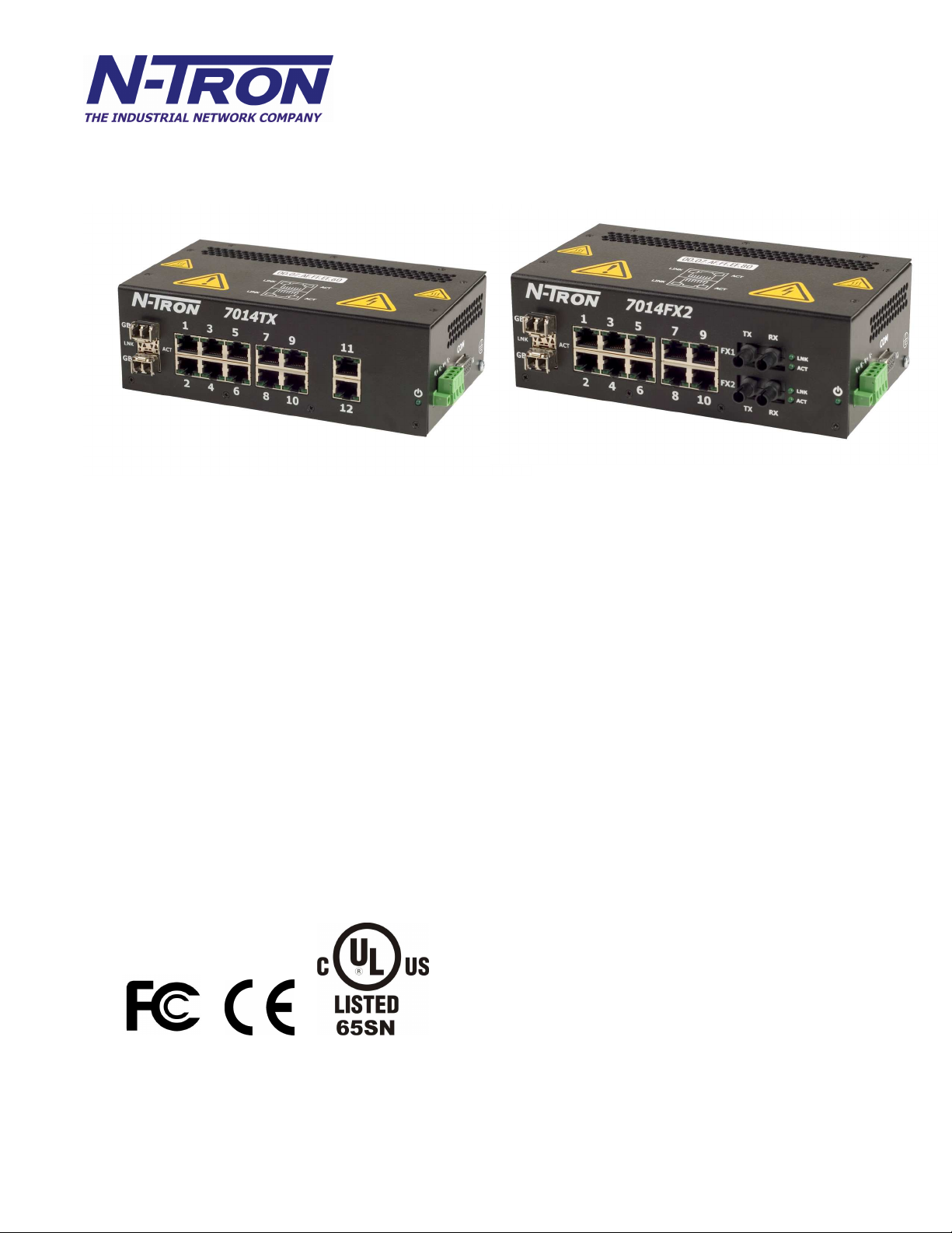
The N-TRON 7014 Series Gigabit compatible Industrial Ethernet Switch offers outstanding performance and ease of use. It is
ideally suited for connecting Ethernet enabled industrial and or security equipment and is a fully managed switch.
PRODUCT FEATURES
• Full IEEE 802.3 Compliance
• Ten 10/100 BaseTX RJ-45 Ports
• Twelve 10/100 BaseTX RJ-45 Ports
(714TX model only)
• Two Optional 1000BaseSX Ports, LC style
• Two Optional 100BaseFX(E) Ports
(7014FX2 and 7014 FXE2 models only)
• Extended Environmental Specifications
• Autosensing 10/100BaseTX, Duplex, and MDIX
• Offers Rapid Spanning Tree Protocol
• Trunk with a 500 Series Switch over two or more ports
• Store & Forward Technology
• Plug and Play IGMP Support
• Rugged Din-Rail Enclosure
• Redundant Power Inputs (10-30 VDC)
• Full SNMP
• Web Browsing and N-View Switch Monitoring
PRODUCT CONFIGURATIONS
• 7014TX – Twelve 10/100 Base-TX RJ45 Copper Ports,
and two optional SFP transceivers
• 7014FX2 – Ten 10/100 Base-TX RJ45 Copper Ports, two
multimode 100BaseFX Ports (SC or ST), and
two optional SFP transceivers
• 7014FXE2 –Ten 10/100 Base-TX RJ45 Copper Ports, two
singlemode 100BaseFX Ports (ST or SC)
(15, 40, or 80 km) and two optional SFP transceivers
MANAGEMENT FEATURES
• IGMP Snooping
• VLAN
• QoS
• Trunking
• Mirroring
• 802.1D-2004 Rapid Spanning Tree
• N-RING™ (N-Tron proprietary Ring Management)
6/28/2007 page 7 of 145
Page 8

Copyright, © N-Tron Corp., 2007
820 S. University Blvd., Suite 4E
Mobile, AL 36609 USA
All rights reserved. Reproduction, adaptation, or translation without prior written permission from N-Tron Corp. is prohibited, except as allowed
under copyright laws.
Ethernet is a registered trademark of Xerox Corporation. All other product names, company names, logos or other designations mentioned
herein are trademarks of their respective owners.
The information contained in this document is subject to change without notice. N-Tron Corp. makes no warranty of any kind with regard to
this material, including, but not limited to, the implied warranties of merchantability or fitness for a particular purpose. In no event shall N-Tron
Corp. be liable for any incidental, special, indirect, or consequential damages whatsoever included but not limited to lost profits arising out of
errors or omissions in this manual or the information contained herein.
Warning
Do not perform any services on the unit unless qualified to do so. Do not substitute unauthorized parts or make unauthorized modifications to
the unit.
Do not operate the unit with the top cover removed, as this could create a shock or fire hazard.
Do not block the air vents on the sides or the top of the unit.
Do not operate the equipment in the presence of flammable gasses or fumes. Operating electrical equipment in such an environment constitutes
a definite safety hazard.
Do not operate the equipment in a manner not specified by this manual.
Safety Warnings
GENERAL SAFETY
WARNING: If the equipment is used in the manner not specified by N-Tron Corp., the protection provided by the equipment may be
impaired.
LASER SAFETY (FXE Models -40, -80 and optional SFP-LX -40, -70 and -80)
WARNING: CLASS 1 LASER PRODUCT. DO NOT STARE INTO THE LASER..
Contact Information
N-Tron Corp.
820 South University Blvd.
Suite 4E
Mobile, AL 36609
TEL: (251) 342-2164
FAX: (251) 342-6353
WEBSITE: www.n-tron.com
E-MAIL: support@n-tron.com
6/28/2007 page 8 of 145
Page 9

ENVIRONMENTAL SAFETY
WARNING: Disconnect the power and allow to cool 5 minutes before touching.
ELECTRICAL SAFETY
WARNING: Disconnect the power cable before removing any modules, or any enclosure panel.
WARNING: Do not operate the unit with the any cover removed.
WARNING: Do not work on equipment or cables during periods of lightning activity.
WARNING: Do not perform any services on the unit unless qualified to do so.
WARNING: Do not block the air vents.
WARNING: Observe proper DC Voltage polarity when installing power input cables. Reversing voltage polarity can cause permanent damage
to the unit and void the warranty.
7014 Series Hazardous Location Installation Requirements
1. WARNING: Explosion Hazard, do not disconnect while circuit is live, unless area is known to be non-hazardous.
2. WARNING: Explosion Hazard - do not replace the device unless power has been switched off or the area is know to be
non-hazardous.
3. WARNING: Input and output wiring must be in accordance with Class I, Div 2, and in accordance with Local &
National Codes of Authorities Having Jurisdiction.
4. WARNING: Explosion Hazard – Substitution of Components May Impair Suitability For Class I, Div. 2.
5. This equipment is suitable for use in Class I, Div. 2, Groups A, B, C, D or non-hazardous locations only.
6. Power must be supplied by an isolating source, and a 3.0 A max rated UL recognized fuse must be installed immediately
before the unit.
7. Class I, Div 2 installations require that all devices connected to this product must be UL listed for the area in which it is
installed.
8. Use 60/175°C rated Copper wire, (0.22Nm) 2 inch-lbs Tightening torque for field installed conductors.
6/28/2007 page 9 of 145
Page 10

PACKAGE CONTENTS
Please make sure the 7014 Series Gigabit Ethernet Switch package contains the following items:
1. 7014 Series Switch
2. Product CD
Contact your carrier if any items are damaged.
Installation
Read the following warning before beginning the installation:
WARNING
Never install or work on electrical equipment or cabling during periods of lightning activity. Never connect or disconnect power
when hazardous gasses are present.
Disconnect the power cable before removing any enclosure panel.
UNPACKING
Remove all the equipment from the packaging, and store the packaging in a safe place. File any damage claims with the carrier.
CLEANING
Clean only with a damp cloth.
6/28/2007 page 10 of 145
Page 11
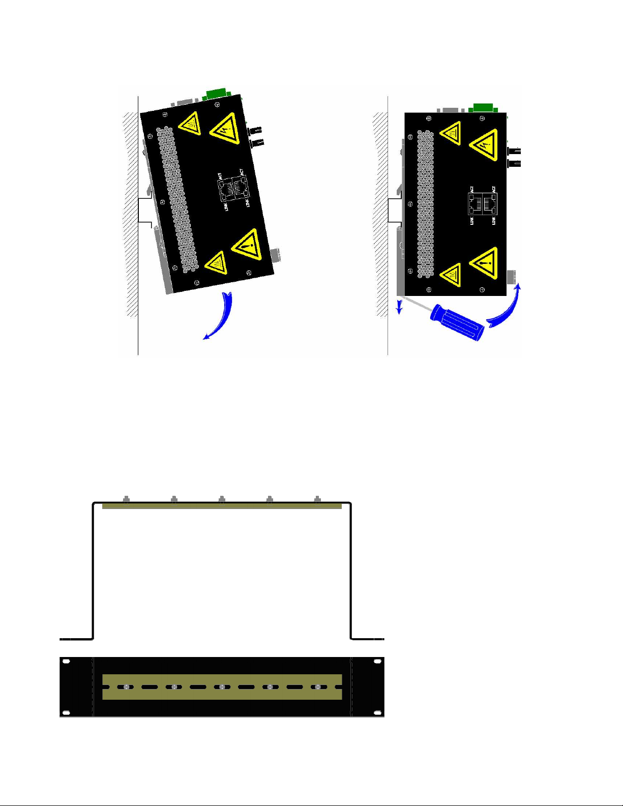
DIN RAIL MOUNTING
Install the unit on a standard 35mm Din-Rail. Recess the 7014TX unit to allow at least 3” of horizontal clearance for fiber cable
bend radius. Recess the 7014FX2 unit to allow at least 5” of horizontal clearance for fiber cable bend radius.
To mount the unit to the 35mm din-rail, place top edge of the bracket
on the back of the unit against the din-rail at an upward angle. Lower
the bottom of the unit until it snaps into place.
To remove the unit from the 35mm din-rail, place a flat
head screwdriver into the release clip at the bottom of the
unit, and push down on the clip until it disengages from
the bottom of the unit from the din-rail. Lift the bottom of
the unit up at an approximate 45° upward angle to
completely remove the unit.
Most N-Tron™ products are designed to be
mounted on industry standard 35mm DINRail. However, DIN-Rail mounting may not
be suitable for all applications. Our Rack
Mount Assembly (P/N: 900-RM) may be
used to mount the 7014 Series to standard
19" racks as an option.
6/28/2007 page 11 of 145
Page 12
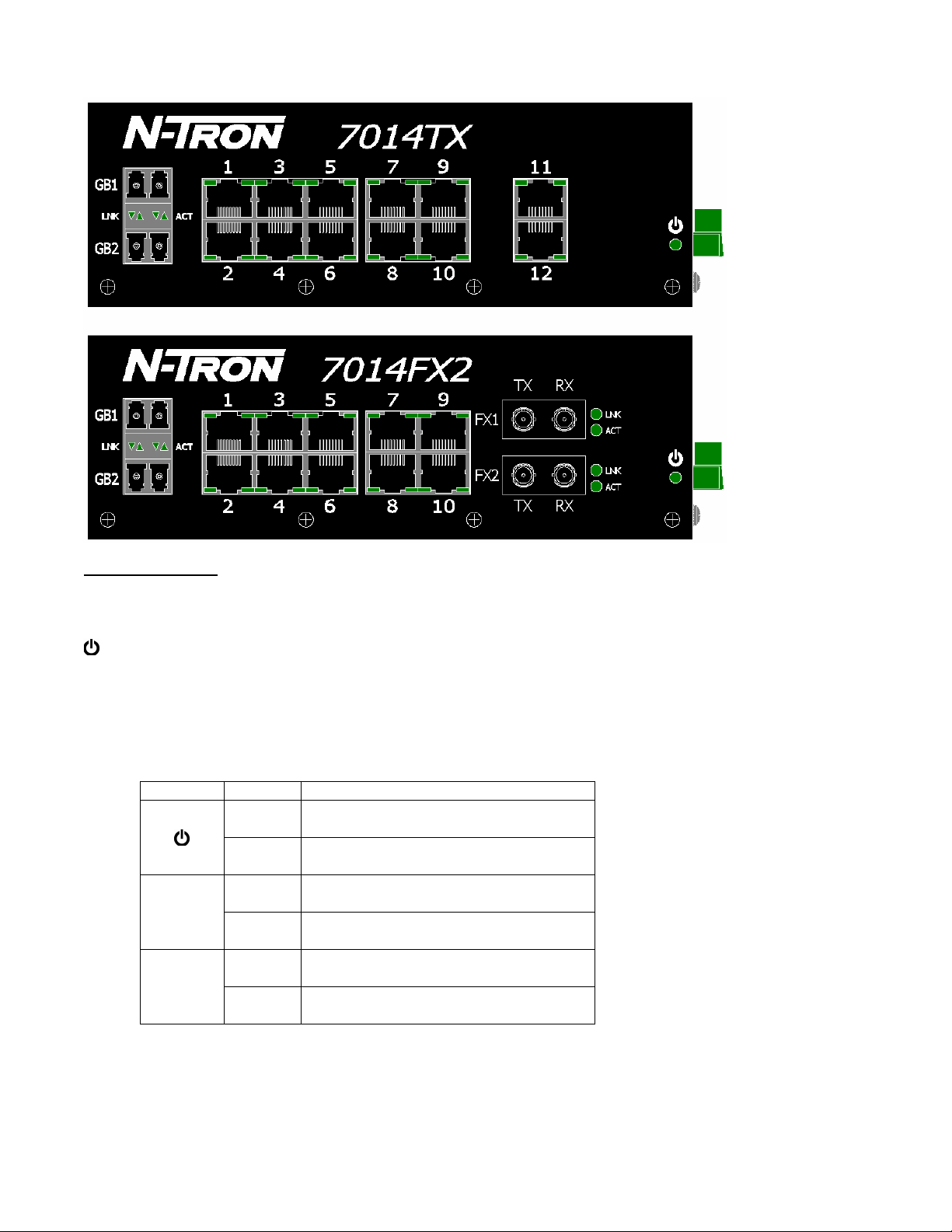
FRONT PANEL
From Top to Left:
Gigabit Ports 1000 Base SFP Fiber Transceivers (Optional)
RJ45 Ports Auto Sensing 10/100 Base-TX Connections
Fiber Ports 100 Base-FX Connections (only on 7014FX2 model)
Green LED lights when Power is supplied to the unit
NOTE: The RJ45 data port has two LED’s located on each connector. The left LED indicates LINK status,
and the right LED indicates ACTIVITY.
LED’s: The table below describes the operating modes:
LED Color Description
GREEN Power is Applied
LNK
ACT
OFF Power is OFF
GREEN 10/100/1000Mb Link between ports
OFF No Link between ports
GREEN Data is active between ports
OFF Data is inactive between ports
6/28/2007 page 12 of 145
Page 13

APPLYING POWER (Side View)
• Unscrew & Remove the DC Voltage Input
Plug from the Power Input Header
• Install the DC Power Cables into the Plug
(observing polarity).
• For best results keep the power cable length
to a maximum of one (1) meter.
• Plug the Voltage Input Plug back into the
Power Input Header.
• Tightening torque for the terminal block
power plug is 0.5 Nm/0.368 Pound Foot.
• Verify the Power LED stays ON (GREEN).
Note: Only 1 power supply must be connected to power for minimal operation. For redundant power
operation, V1 and V2 inputs must be connected to separate DC Voltage sources. This device will draw
current from both sources simultaneously. Use 16-28 gauge wire when connecting to the power supply.
Recommended 24V DC Power Supplies, similar to: N-Tron’s P/N NTPS-24-3:
• Input AC 115/230V
• Output DC 24-28V
• Output Current 3A @ 24V
2.6A @ 28V
• Power 72W
• 35 mm DIN-Rail Mountable
• Dimensions: 45X75X91 mm
6/28/2007 page 13 of 145
Page 14
Connecting the Unit
For FX/FXE units, remove the dust cap from the fiber optic connectors and connect the fiber optic cables.
The TX port on the FX/FXE models should be connected to the RX port of the far end station. The RX port
on the FX/FXE versions should be connected to the TX port of the far end station.
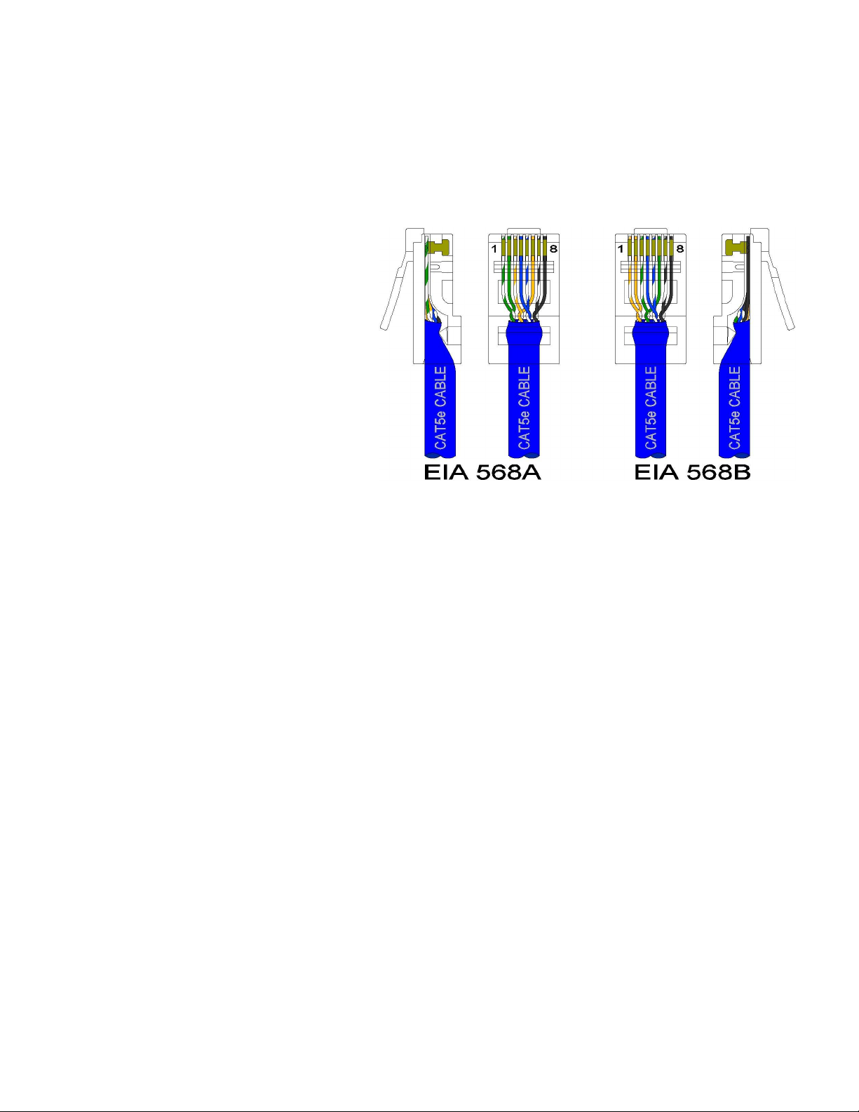
For 10/100 Base-TX ports, plug a Category 5E twisted pair cable into the RJ45 connector. Connect the
other end to the far end station. Verify that the LNK LED’s are ON once the connection has been
completed. To connect any port to another device (end node, Switch or Repeater), use a standard Category
5E straight through or crossover cable
with a minimum length of one meter and a
maximum length of 100 meters..
N-Tron recommends the use of premanufactured Cat5E cables to ensure the
best performance. If this is not an option
and users must terminate their own ends
on the Cat5E cables; one of the two color
coded standards shown to the right should
be utilized. If a user does not follow one
of these two color code standards then the
performance and maximum cable distance
will be reduced significantly, and may
prevent the switch from establishing a
link.
6/28/2007 page 14 of 145
Page 15
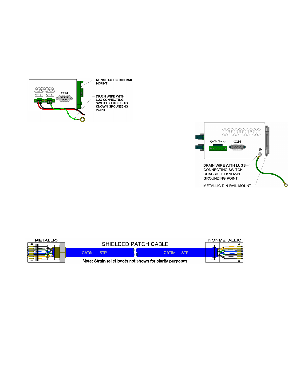
N-TRON SWITCH GROUNDING TECHNIQUES
The grounding philosophy of any control system is an integral part of the design. N-Tron switches are
designed to be grounded, but the user has been given the flexibility to float the switch when required. The
best noise immunity and emissions (i.e. CE) are obtained when the N-Tron switch chassis is connected to
earth ground via a drain wire. Some N-Tron switches have metal din-rail brackets that can ground the
switch if the din-rail is grounded. In some cases, N-Tron switches with metal brackets can be supplied with
optional plastic brackets if isolation is required.
Both V- legs of the power input connector are connected
to chassis internally on the PCB. Connecting a drain wire
to earth ground from one of the V- terminal plugs as
shown here will ground the switch and the chassis. The
power leads from the power source should be limited to 3
meters or less in length.
As an alternate, users can run a drain wire & lug from any of the DinRail screws or empty PEM nuts on the enclosure. When using an
unused PEM nut to connect a ground lug via a machine screw, care
should be taken to limit the penetration of the outer skin by less than 1/4
in. Failure to do so may cause irreversible damage to the internal
components of the switch.
Note: Before applying power to the grounded switch, you must use a
volt meter to verify there is no voltage difference between the power
supply’s negative output terminal and the switch chassis grounding
point.
The use of shielded cables between devices is not required for most N-Tron devices (please consult the user
manuals for specific details). If the use of shielded cables is required, it is generally recommended to only
connect the shield at one end to prevent ground loops and interfere with low level signals (i.e.
thermocouples, RTD, etc.). Cat5e cables manufactured to EIA-568A or 568B specifications are required for
use with N-Tron Switches.
In the event all Cat5e patch cable distances are small (i.e. All Ethernet devices are located the same local
cabinet and/or referenced to the same earth ground), it is permissible to use fully shielded cables terminated
to chassis ground at both ends in systems void of low level analog signals.
6/28/2007 page 15 of 145
Page 16
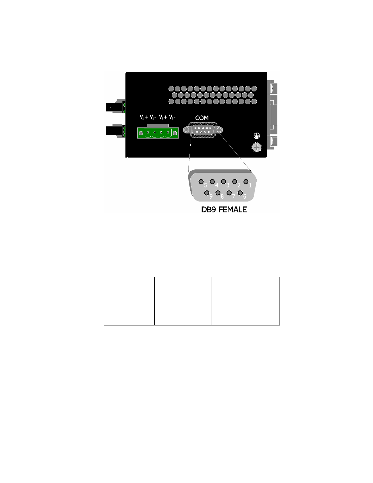
SERIAL INTERFACE
The 7014 Series switches provide an EIA-232 interface accessed via a 9 pin female connector (labeled
‘COM’ on the unit). This is used to access the Command Line Interpreter (CLI). The pin-outs are shown
below:
Serial Cable
Connect the serial COM port of your PC and the 7014 Series Switch using a standard straight through cable.
You will require a cable with a 9-pin or 25-pin sub-D female connector for the PC end, and a 9-pin male
sub-D connector for the 7014 Series end.
The following table shows the pin-out and the connections for both types of cable:
PC Port 25-Pin 9-Pin 7014 series
Female Female
Signal Name Pin # Pin # Pin # Signal Name
TXD 2 3 3 RXD
RXD 3 2 2 TXD
GND 7 5 5 GND
9-Pin Male
Shielded cables and null modems are readily available from Radio Shack or a variety of computer stores.
HyperTerminal
The following configuration should be used in HyperTerminal:
Port Settings: 115200
Data Bits: 8
Parity: None
Stop bits: 1
Flow Control: None
6/28/2007 page 16 of 145
Page 17

Overview of Advanced Features
Mode of Operation
Each port on the switch can be configured into different modes of operation as shown below:
Copper Ports: 100Base Fiber Ports: 1000Base Fiber Ports:
- Half Duplex - Full Duplex - Full Duplex
- Full Duplex
- Auto Negotiation
Half Duplex
In half duplex mode, the CSMA/CD media access method is the means by which two or more stations share
a common transmission medium. To transmit, a station waits (defers) for a quiet period on the medium (that
is, no other station is transmitting) and then sends the intended message in bit-serial form. If, after initiating
a transmission, the message collides with that of another station, then each transmitting station intentionally
transmits for an additional predefined period to ensure propagation of the collision throughout the system.
The station remains silent for a random amount of time (backoff) before attempting to transmit again.
Full Duplex
Full duplex operation allows simultaneous communication between a pair of stations using point-to-point
media (dedicated channel). Full duplex operation does not require that transmitters defer, nor do they
monitor or react to receive activity, as there is no contention for a shared medium in this mode.
Auto Negotiation
In Auto Negotiation mode the port / hardware detects the mode of operation of the station that is connected
to this port and sets its mode to match the mode that of the station.
Port Security
Port Security provides a mechanism to detect any intruder in the network. When security is enabled on the
port, the port stops learning new MAC addresses on that port and if it receives any packet with a source
MAC address that is not in the address table, the packet will be discarded.
Port Mirroring
A Mirroring Port is a dedicated port that is configured to receive the copies of Ethernet frames that are being
transmitted out and also being received in from any other port that is being monitored.
Port Trunking
Port Trunking is the ability to group two or more network ports to increase the bandwidth between two
machines (switch or any work station). This feature allows grouping of high-speed connectivity and
provides redundant connection between switches, so that trunk can act as a single link between the switches.
6/28/2007 page 17 of 145
Page 18

Priority Tagging (QoS)
IEEE 802.1p priority tagging is supported for two classes of services along with bandwidth support per
priority level. Transparent mode is supported through configuration wherein if the field is set, the tag bits
are ignored. The User can configure up to 8 different priority levels per port. Also priority overriding
(overriding the tagged field) can be enabled or disabled by the user.
Virtual LAN
The switch provides support for setting up both tagged Virtual LANs and port based Virtual LANs. A port
may belong to any number of Virtual LANs. The VLAN membership of a station is determined by the
VLAN(s) that have been defined for the port to which the station is connected. If a station should move
from one port to another, it loses its current VLAN membership and inherits that of the new port it is
connected to.
A Default Virtual LAN exists to which a port, which is not a member of any other Virtual LAN, will
belong. This allows the switch to operate as a ‘normal’ Bridge when it is used in a network. A port is
automatically removed from the Default VLAN when it is reconfigured to belong to another Virtual LAN.
Using Tagged VLANs the switch has the ability to take non-tagged packets in some ports, add a VLAN tag
to the packet and send it out tagged ports on the switch. The VLANs can also be configured to accept
tagged packets in tagged ports, strip the tags off the packets, and send the packets back out other untagged
ports. This allows a network administrator to set up the switch so he can support devices on the network
that do not support VLAN Tagged packets. The administrator can also set up the ports to discard any
packets that are tagged or to discard any packets that are untagged based on a hybrid VLAN of both tagged
and untagged ports, and using the VLAN Ingress Filter on the switch.
The 7014 Series switch also has the ability to allow overlapping VLANs. Overlapping VLANs gives the
user the ability to have one or more ports share two or more VLAN groups. For more information and
examples on how this could be implemented please see our website’s technical documents.
Rapid Spanning Tree Protocol
The rapid spanning tree protocol as specified in IEEE 802.1D-2004 is supported. One Spanning Tree per a
unit is supported. Besides a Spanning Tree per VLAN is also supported.
The Rapid Spanning Tree Protocol (RSTP) supersedes the Spanning Tree Protocol (STP) which was
described in IEEE 802.1D-1998. The RSTP is used to configure a simply connected active network
topology from the arbitrarily connected bridges of a bridged network. Bridges effectively connect just the
LANs to which their forwarding ports are attached. Ports that are in a blocking state do not forward frames.
The bridges in the network exchange sufficient information to automatically derive a spanning tree.
RSTP allows for much quicker learning of network topology changes than the older STP. RSTP supports
new and improved features such as rapid transition to forwarding state. RSTP also sends out new BPDUs
every hello time instead of just relaying them. RSTP interoperates with older STP switches by falling back
to the older STP when the older BPDUs are detected on bridge ports. The user can also manually configure
bridge ports to use the older STP when desired.
6/28/2007 page 18 of 145
Page 19

SNMP Traps
The 7014 Series switch supports up to 5 SNMP Trap Stations to which SNMP Traps will be sent. The
switch supports three standard traps; Link Up, Link Down, and Cold Start. SNMP Traps will be sent to all
the stations configured on the switch if a port Link goes up or down, and when the switch first powers up.
IGMP Snooping
IGMP Snooping is enabled by default, and the switch is Plug and Play for IGMP. IGMP snooping provides
intelligent network support for multicast applications. In particular, unneeded traffic is reduced. IGMP
Snooping is configured via the console and if enabled, then operates dynamically upon each power up.
Also, there can be manual only or manual and dynamic operation. Note that “static multicast group
address” can be used whether IGMP Snooping is enabled or not.
IGMP Snooping will function dynamically without user intervention. If some of the devices in the LAN do
not understand IGMP, then manual settings are provided to accommodate them. The Internet Group
Management Protocol (IGMP) is a protocol that provides a way for a computer to report its multicast group
membership to adjacent ‘routers’. In this case N-Tron 7014 series switches provide router-like
functionality. Multicasting allows one computer to send content to multiple other computers that have
identified themselves as interested in receiving the originating computer's content. Multicasting can be used
to transmit only to an audience that has joined (and not left) a multicast group membership. IGMP version 2
is formally described in the Internet Engineering Task Force (IETF) Request for Comments (RFC) 2236.
IGMP version 1 is formally described in the Internet Engineering Task Force (IETF) Request for Comments
(RFC) 1112. The 7014 series supports v1 and v2.
N-Ring
N-Ring is enabled by default, and the switch is Plug and Play for N-Ring except that initially one must
enable an N-Ring enabled device to be the N-Ring Manager for a given N-Ring. Subsequently,
N-Ring operates dynamically upon each power up. Using N-Tron's proprietary N-Ring technology offers
expanded ring size capacity, detailed fault diagnostics, and a standard healing time of 30ms. The N-Ring
Manager periodically checks the health of the N-Ring via health check packets. If the N-Ring Manager
stops receiving the health check packets, it times out and converts the N-Ring to a backbone within 30ms.
When using all N-Ring enabled switches in the ring, a detailed ring map and fault location chart is also
provided on the N-Ring Manager’s web browser. N-Ring status is also sent from the N-Ring Manager to
the N-View OPC Server to identify the health status of the ring. Up to 250 N-Ring enabled switches can
participate in one N-Ring topology. Switches that do not have N-Ring capability may be used in an N-Ring,
however the ring map and fault location chart cannot be as detailed at these locations.
6/28/2007 page 19 of 145
Page 20

TROUBLESHOOTING
1. Make sure the (Power LED) is ON.
2. Make sure you are supplying sufficient current for the version chosen. Note: The Inrush
current will exceed the steady state current by ~ 2X.
3. Verify that Link LED’s are ON for connected ports.
4. Verify cabling used between stations.
5. Verify that cabling is Category 5E or greater for 100Mbit Operation.
SUPPORT
Contact N-Tron Corp. at:
TEL: 251-342-2164
FAX: 251-342-6353
E-MAIL: support@n-tron.com
WEB: www.n-tron.com
FCC STATEMENT
This product complies with Part 15 of the FCC-A Rules.
Operation is subject to the following conditions:
(1) This device may not cause harmful Interference
(2) This device must accept any interference received, including interference that may cause
undesired operation.
NOTE: This equipment has been tested and found to comply with the limits for a Class A digital device,
pursuant to Part 15 of the FCC Rules. These limits are designed to provide reasonable protection against
harmful interference in a residential installation. This equipment generates, uses, and can radiate radio
frequency energy and, if not installed and used in accordance with the instructions, may cause harmful
interference to radio communications. Operation of this device in a residential area is likely to cause
harmful interference in which case the user will be required to correct the interference at his own
expense.
INDUSTRY CANADA
This Class A digital apparatus meets all requirements of the Canadian Interference Causing Equipment
Regulations. Operation is subject to the following two conditions; (1) this device digital apparatus meets
all requirements of the Canadian Interference Causing Equipment Regulations. Operation is subject to
the following two conditions; (1) this device may not cause harmful interference, and (2) this device
must accept any interference received, including interference that may cause undesired operation.
Cet appareillage numérique de la classe A répond à toutes les exigences de l'interférence canadienne
causant des règlements d'équipement. L'opération est sujette aux deux conditions suivantes: (1) ce
dispositif peut ne pas causer l'interférence nocive, et (2) ce dispositif doit accepter n'importe quelle
interférence reçue, y compris l'interférence qui peut causer l'opération peu désirée.
6/28/2007 page 20 of 145
Page 21
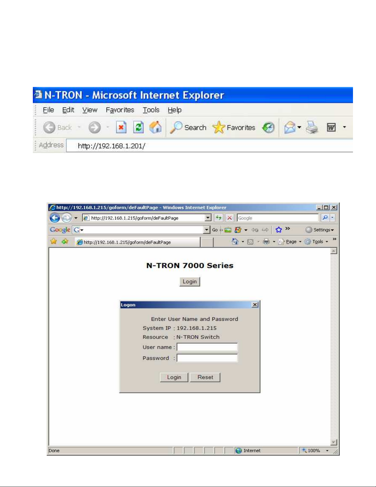
Web Software Configuration
Web Management
Enter the switch’s IP address in any web browser and login to the web management feature of the 7014
Series.
Default:
User Name: admin
Password: admin
6/28/2007 page 21 of 145
Page 22
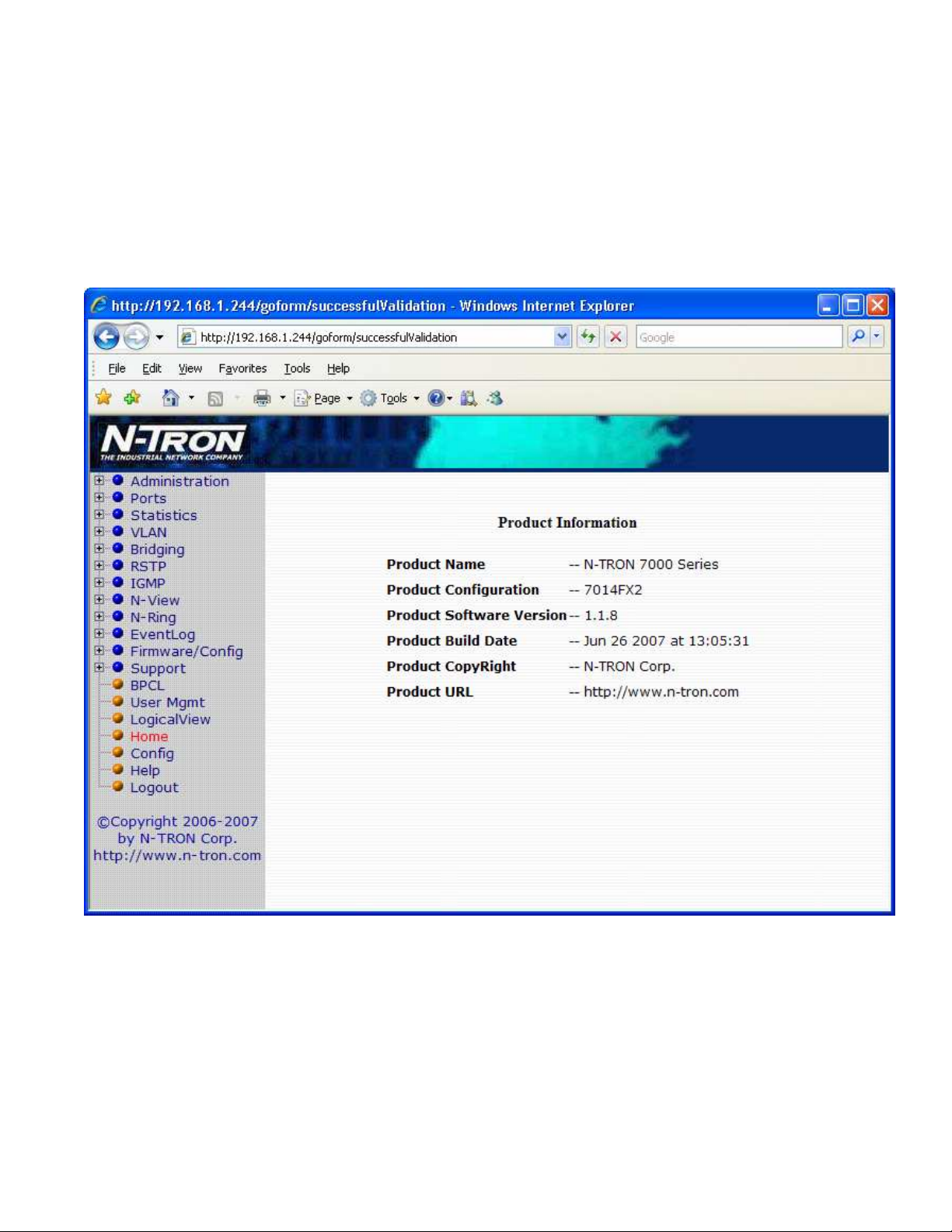
Web Management - Home
When the administrator first logs onto a 7014 Series switch the default home page will be displayed. On the
left hand side of the screen there is a list of configurable settings that the 7014 Series switch will support.
This section of the manual will go through each and every choice listed on the left hand side of the screen
and explain how to configure those settings. In the center of the main home page the administrator can see
some basic information like what firmware revision the switch is running. The firmware can be upgraded at
a later time in the field using TFTP or FTP.
6/28/2007 page 22 of 145
Page 23
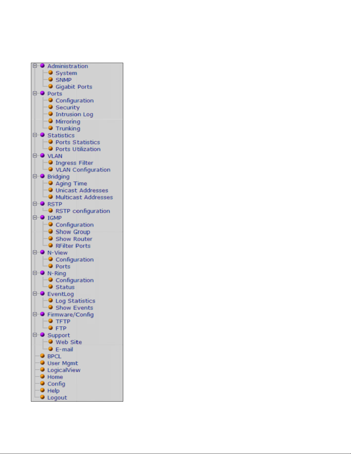
Web Management – Menu Structure
To the left, there is a menu which is shown fully opened below. The pages opened by each of the individual
selections are described in the rest of this section. The use of each of these pages is also described in this
section. In most of the descriptions, only the right side of the page is shown.
6/28/2007 page 23 of 145
Page 24
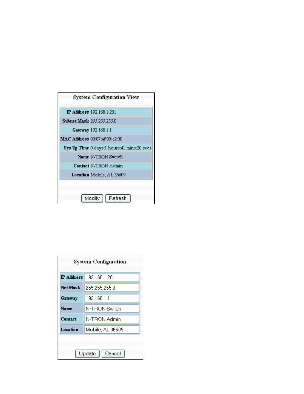
Administration – System
The System tab under the Administration category lists the following information about the switch:
IP Address
Subnet Mask
Default Gateway
MAC Address
System Up Time
Name
Contact Information
Location
By selecting the modify button you will be able to change the switch’s IP Address, Subnet Mask, Default
Gateway, Name, Contact information, and the Location of the switch through the web management features.
It is recommended to change the TCP/IP information through the Command Line Interface (CLI) initially,
but it defaults to the following:
IP Address – 192.168.1.201
Subnet Mask – 255.255.255.0
Default Gateway – 192.168.1.1
6/28/2007 page 24 of 145
Page 25
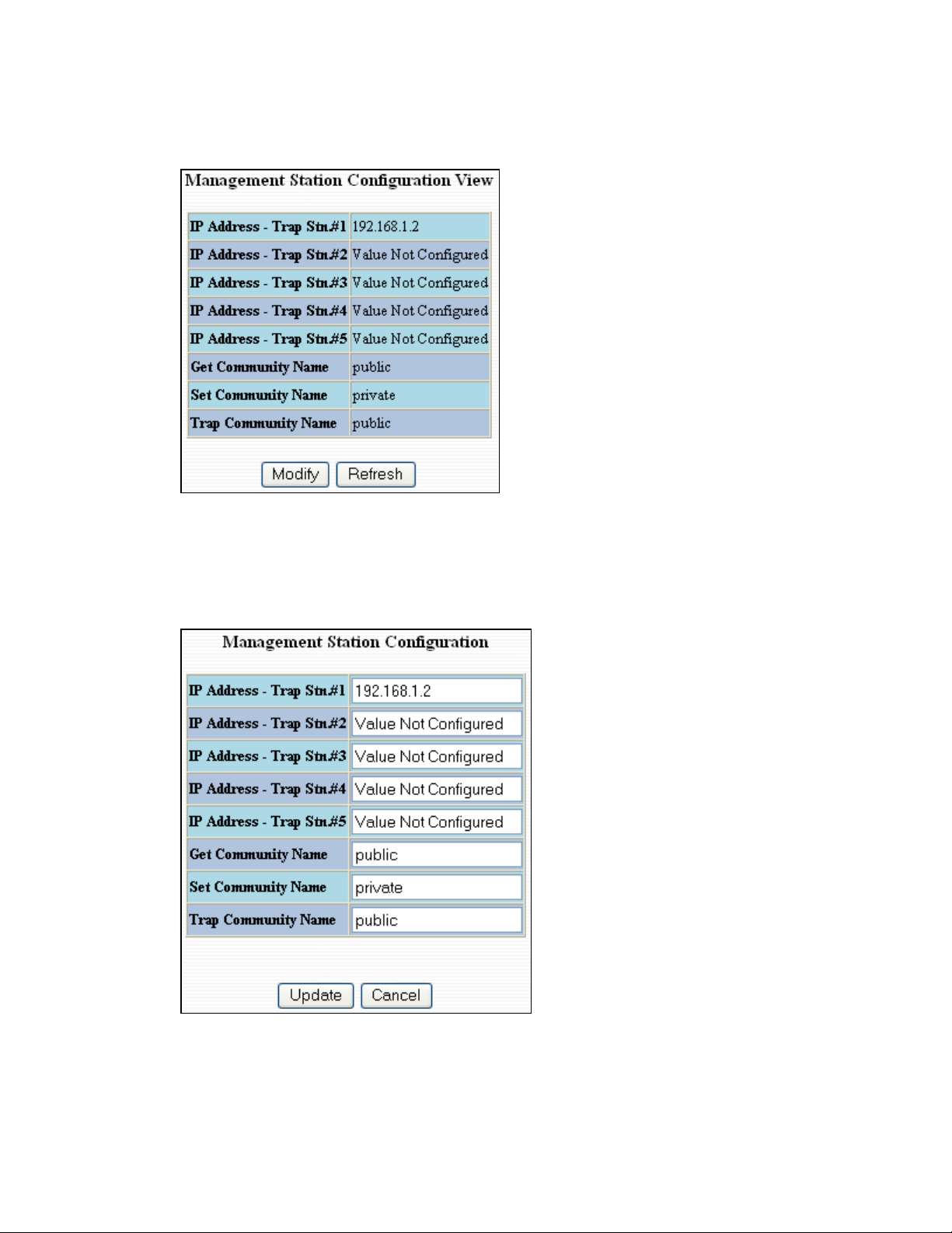
Administration – SNMP
The SNMP tab under the administration category shows a list of IP Addresses that act as SNMP Traps. The
Get, Set, and Trap Community Names are also shown here.
By selecting the modify button you will be able to change any of the fields listed. This allows the user to set
an IP address for an SNMP Trap or change the Community Names. Systems that are listed as an SNMP
Trap will be sent basic networking changes made to the switch such as ports going down or being linked.
To restore a Trap to “Value Not Configured”, enter ‘0.0.0.0’.
6/28/2007 page 25 of 145
Page 26
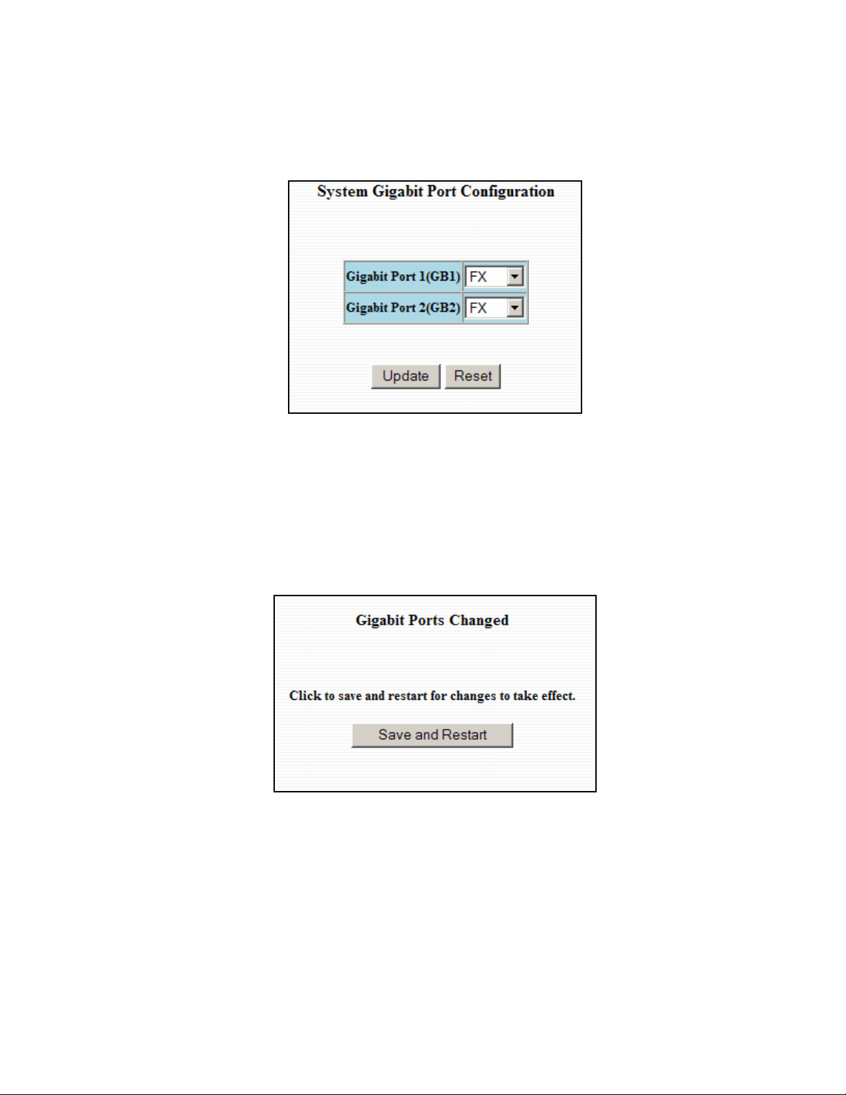
Administration – Gigabit Ports
The ‘Gigabits Ports’ tab under the administration category allows users to change the configuration of the
gigabit ports. The switch may not operate correctly if the slots are not configured properly. You must click
“Update” if you wish to keep the changes.
Following the Update button, the user may be prompted to Save and Restart the switch in order for changes
to take effect. The switch will save the running configuration into the NVRAM and then cycle power
automatically. Once the switch comes back online the settings will be updated.
6/28/2007 page 26 of 145
Page 27
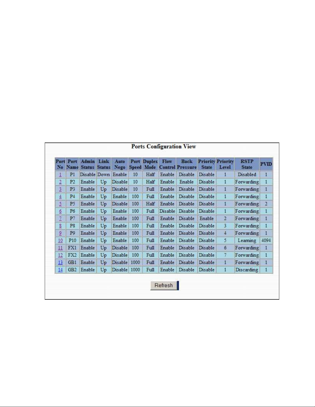
Ports – Configuration
The Configuration tab under the Ports category will show a detailed overview of all the active ports on the
switch. The overview will display the following information:
Port Number
Port Name
Admin Status
Link Status
Auto Negotiation State
Port Speed
Duplex Mode
Flow Control State
Back Pressure State
Priority State
Priority Level
RSTP State
PVID
6/28/2007 page 27 of 145
Page 28
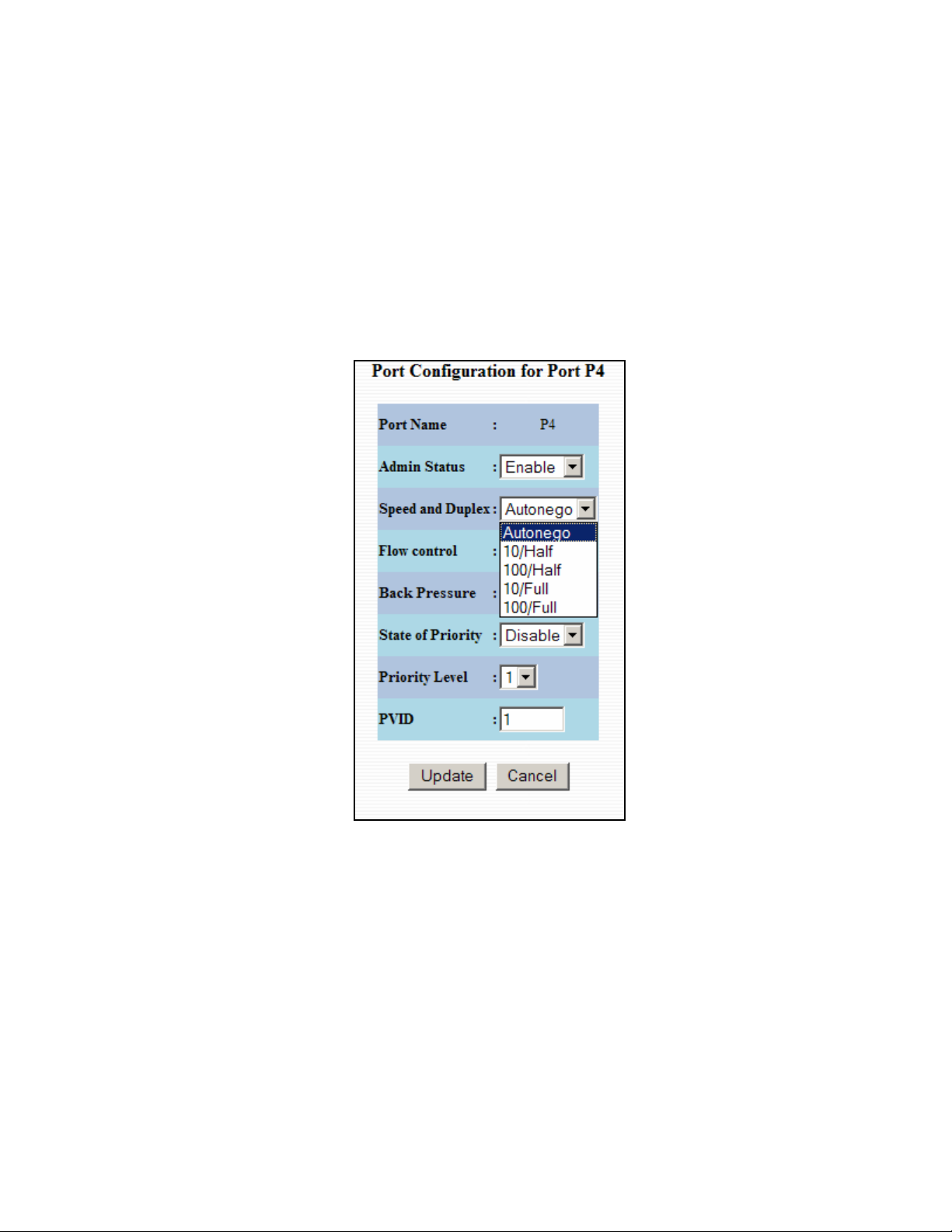
Ports – Configuration, Continued…
The User can click on the Port Number to configure each port individually. This will allow the user to
change the port’s settings for the following fields:
Admin Status
Speed and Duplex
Flow Control
Back Pressure
State of Priority
Priority Level
PVID
6/28/2007 page 28 of 145
Page 29
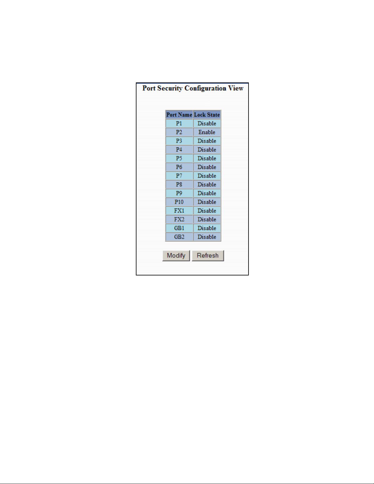
Ports – Security
The Security tab under the Ports category will show a list of all the active ports and the security Lock State
for each port.
6/28/2007 page 29 of 145
Page 30
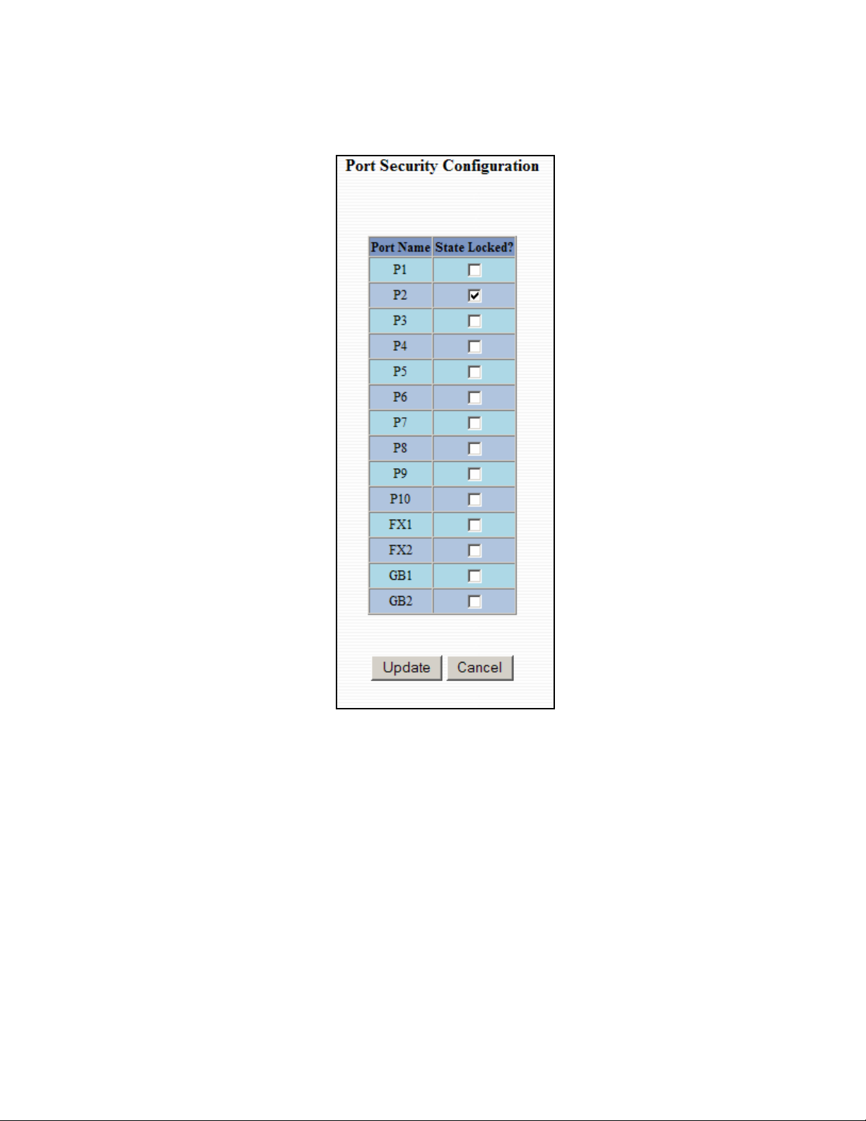
Ports – Security (Continued)
Administrators can change the Port Security by a per port basis. If the Port is enabled through this the port
will be locked and will only allow known MAC addresses to communicate through the port. Unknown
MAC addresses will be logged in the Intrusion Log.
6/28/2007 page 30 of 145
Page 31

Ports – Intrusion Log
The Intrusion Log tab under the Ports category will show a list of intruders along with their MAC addresses.
The log will show what Port the intruder attempted to access your network on and log the system time when
it occurred. The log can be easily cleared.
NOTE: This feature must first be enabled through the CLI before it will function in the web interface.
6/28/2007 page 31 of 145
Page 32

Ports – Mirroring
A mirroring port is a dedicated port that is configured to receive the copies of Ethernet frames that are being
transmitted out and also being received in from any other port that is being monitored.
The Mirroring tab under the Ports category displays the status including the list of Source Ports and the
Destination Port that the Sources are being mirrored to.
Following the Configure button, you can enable the status of port mirroring and select source ports and the
destination port that the source ports will be mirrored to.
NOTE: Since the Gigabit ports cannot be destination ports, they are not available on the pull-down
menu.
6/28/2007 page 32 of 145
Page 33

Ports – Trunking
The Trunking tab under the Ports category displays a list of trunks configured on the switch and the
following details regarding each trunk:
Trunk Name
Trunk Ports
Trunk State
By selecting the “Create” button, you can add a trunk group.
NOTE: RSTP must be disabled in order to use the Trunking Feature.
A maximum of 4 ports of the same speed can constitute a valid trunk.
Only 1 Trunk per switch can be created.
All trunk ports must be at the same speed and duplex mode. If a port is not linked, there could be
difficulty as to similar speed and duplex mode. It is best to hard code speed and duplex mode for
each trunking link, at both ends.
When trunking the gigabit ports it’s best to route switchA GB1 to switchB GB1 and switchA GB2 to
switchB GB2.
Do not use Trunking on a switch that is directly in an active N-Ring.
6/28/2007 page 33 of 145
Page 34

Ports – Trunking, Continued…
Once the Trunk Group is created you will see detailed information for that trunk group, but it should have a
disabled state by default.
In order to enable the Trunk Group you need to click on the State Button above. The following page should
load asking for the Trunk ID and what the Trunk State is.
NOTE: RSTP must be disabled in order to use the Trunking Feature.
A maximum of 4 ports of the same speed can constitute a valid trunk.
Only 1 Trunk per switch can be created.
All trunk ports must be at the same speed and duplex mode. If a port is not linked, there could be
difficulty as to similar speed and duplex mode. It is best to hard code speed and duplex mode for
each trunking link, at both ends.
Do not use Trunking on a switch that is directly in an active N-Ring.
6/28/2007 page 34 of 145
Page 35

Statistics – Port Statistics
The Ports Statistics tab under the Statistics category displays a list of MIB Parameters. Each port has a
separate counter for each parameter. This gives users the ability to see what kind of packets are going over
which ports. At the bottom of each page for each port there are two buttons. Refresh will update the
statistics for that port number and Clear will reset all the counters for that port number.
6/28/2007 page 35 of 145
Page 36

Statistics – Port Utilization
The Ports Utilization tab under the Statistics category shows all the ports on the switch and will display a
bar graph showing the percentage of bandwidth being used. These figures and bars are for a general feeling
of what the bandwidth usage is. N-Tron recommends the use of N-View in order to get a precise bandwidth
usage figure.
6/28/2007 page 36 of 145
Page 37

VLAN – Ingress Filter
The Ingress Filter tab under the VLAN category shows all the Ingress Filter Rule enabled or disabled state
for each port. Ingress Filtering can be Enabled or Disabled for each port. If enabled, received frames will be
discarded if the frame's VID does not match any VLAN IDs associated with the port. This implements IEEE
802.1Q clause 8.6.
6/28/2007 page 37 of 145
Page 38

To change the Ingress Filter Rule simply click on the Modify button on the page above, select the port
number from the pull down menu that you wish to modify and then choose to either enable or disable the
Ingress Filter Rule.
NOTE: The Ingress Filter will automatically be turned on for respective ports when tagged VLANs are
created, but may not automatically turn off if you change a tagged VLAN to a port based VLAN.
6/28/2007 page 38 of 145
Page 39

VLAN – Port Based
The Port Based tab under the VLAN category shows all the VLANs that are configured on the switch and
details about the VLANs such as port numbers and tagged VLAN settings.
To add a VLAN simply click on the Add button on the page above and fill in the desired fields. The
example below would set up a basic port based VLAN for ports P1-P6.
(See VLAN Configuration Examples section)
Note:
1. When implementing overlapping VLANs, RSTP can only be enabled on one of the VLANs that is
overlapping others. RSTP can not be implemented on a VLAN that contains other VLANs within
that one. Changing anything on a VLAN will turn on RSTP on all VLANS as a precautionary
measure.
2. VLANs on N-Ring ports are limited to VID=1 (default) or VID=2. All N-Ring ports must be on
the same tagged VLAN.
3. VID=1 has to be Admit=ALL, and cannot be tagged only.
6/28/2007 page 39 of 145
Page 40

VLAN – Port Based, Continued…
Now the page will display the new VLAN and moved ports P1-P6 from the default VLAN down to vlan2
that was just created.
To delete or remove VLANs that are no longer wanted simply click on the Delete button on the main Port
Based VLAN page. That button will load the page where the user can enter the VLAN ID that he or she
wishes to delete.
(See VLAN Configuration Examples section)
Note:
1. When implementing overlapping VLANs, RSTP can only be enabled on one of the VLANs that is
overlapping others. RSTP can not be implemented on a VLAN that contains other VLANs within
that one. Changing anything on a VLAN will turn on RSTP on all VLANS as a precautionary
measure.
2. VLANs on N-Ring ports are limited to VID=1 (default) or VID=2. All N-Ring ports must be on
the same tagged VLAN.
3. VID=1 has to be Admit=ALL, and cannot be tagged only.
6/28/2007 page 40 of 145
Page 41

VLAN – Port Based, Continued…
Once the VLAN is deleted it will no longer appear on the main page and all the ports are now back under
the default VLAN. When a port based VLAN is created the PVID (Port VLAN ID) will change
automatically to be members of the new VLAN they are a part of. If you delete this VLAN the PVIDs will
not automatically return to the default VLAN. Users should keep this in mind when removing VLANs, and
may need to manually change the PVIDs for any affected ports.
(See VLAN Configuration Examples section)
Note:
1. When implementing overlapping VLANs, RSTP can only be enabled on one of the VLANs that is
overlapping others. RSTP can not be implemented on a VLAN that contains other VLANs within
that one. Changing anything on a VLAN will turn on RSTP on all VLANS as a precautionary
measure.
2. VLANs on N-Ring ports are limited to VID=1 (default) or VID=2. All N-Ring ports must be on
the same tagged VLAN.
3. VID=1 has to be Admit=ALL, and cannot be tagged only.
6/28/2007 page 41 of 145
Page 42

Bridging – Aging Time
The Aging Time tab under the Bridging category will display the currently configured Aging Time. This
page allows users to modify this variable to meet their needs.
After selecting the Modify button the user will be presented with a page that allows the number to be
entered into and updated. The default aging time is 20 seconds.
6/28/2007 page 42 of 145
Page 43

Bridging – Unicast Addresses
The Unicast Addresses tab under the Bridging category will display a list of MAC addresses that are
associated with each respective port number. This can be used to statically assign a MAC address access to
a single port on the switch.
Following the Add button on the page above, the administrator must enter a valid MAC address and
associate it with a port number on the switch. Once the administrator hits the Update button the changes
will take effect instantly.
Once a static MAC address has been added, it will be displayed in a list on the main page under Unicast
MACs tab.
6/28/2007 page 43 of 145
Page 44

Bridging – Unicast Addresses, Continued…
Following the Delete button on the page above, an administrator can select a static MAC address from the
list using a pull down menu. After selecting the MAC address the administrator needs to press the Delete
button on this page to remove the entry
.
6/28/2007 page 44 of 145
Page 45

Bridging – Multicast Addresses
The Multicast Addresses tab under the Bridging category will display a list of Multicast Group Addresses
that are associated with respective port numbers. This may be used to statically assign a Multicast Group
Address access to a group of ports on the switch.
Following the Add button on the page above, the administrator must enter a valid Multicast Group Address
and associate it with a port number or list on the switch. Once the administrator clicks on the Update
button, the changes will take effect instantly.
Note: If there are multiple ports on different VLANs, the 7014 will apply the static multicast address to the
lowest VLAN-ID that is associated with one of the ports assigned to the static multicast address. So if
the lowest VLAN-ID contains all the ports assigned to the static multicast address (an umbrella
VLAN), it will function for all those ports with no problems. This can be achieved with overlapping
VLANs.
6/28/2007 page 45 of 145
Page 46

Bridging – Multicast Addresses, Continued…
After adding a Multicast Group Address it will appear on the main list and will show the associated ports
that go along with that address.
Following the Delete button on the page above, the administrator will be presented with a list of Multicast
Group Addresses that are configured on the switch. Using the pull down menu the administrator should
select the desired port to be removed. Then click on the Delete button at the bottom of the page.
Note: If there are multiple ports on different VLANs, the 7014 will apply the static multicast address to the
lowest VLAN-ID that is associated with one of the ports assigned to the static multicast address. So if
the lowest VLAN-ID contains all the ports assigned to the static multicast address (an umbrella
VLAN), it will function for all those ports with no problems. This can be achieved with overlapping
VLANs.
6/28/2007 page 46 of 145
Page 47

RSTP – RSTP Configuration
The RSTP Configuration tab under the RSTP category will display the RSTP information for the first
VLAN. Using the pull down menu at the top of the page an administrator can choose which VLAN to
configure RSTP on. Once the VLAN is selected the administrator may configure the bridge by clicking on
the Configuration button in the middle of the page.
The configuration screen for the VLAN that was previously selected will look like the example below. Here
the administrator can make changes such as the Hello Time, the Forward Delay, the Max Age, the priority,
and the Status of RSTP on that VLAN. Following the link for the view RSTP Port Configuration at VLAN#
the administrator or user can see the current RSTP status of the ports on that VLAN.
NOTE: Trunking must be disabled in order to use RSTP.
6/28/2007 page 47 of 145
Page 48

RSTP Configuration, Continued…
Following the link for the view RSTP Port Configuration at VLAN# the administrator or user can see the
current RSTP status of the ports on that VLAN. This will show information such as the Path Cost and the
Port State. If the switch sees a redundant path it will put the port with the highest Path Cost into Blocking
mode where it will discard packets coming in on that port. In the below example, P12 is a redundant port
with port P2, therefore P2 is forwarding and P12 is discarding.
6/28/2007 page 48 of 145
Page 49

RSTP – RSTP Configuration, Continued…
If the administrator selects one of the ports on the previous screen he or she can change the Port’s Path Cost,
Port’s Priority and the status of Admin Edge and Auto Edge.
6/28/2007 page 49 of 145
Page 50

IGMP – Configuration
The Configuration tab under the IGMP category will display the IGMP basic configuration settings. By
default IGMP is enabled.
Following the Modify button on the previous page, the administrator will see a list of configurable fields for
the IGMP configuration. Once these fields are filled in to meet the needs of the administrator’s network the
changes may be saved by clicking the Update button at the bottom of the page.
6/28/2007 page 50 of 145
Page 51

IGMP – Configuration (continued)
The IGMP Status pulldown allows the user to enable or disable IGMP completely.
The Query Mode pulldown allows the user to set query mode for automatic (the default), On (always), or off
(never):
6/28/2007 page 51 of 145
Page 52

IGMP – Configuration (continued)
The Router Mode pulldown allows the user to choose router mode. ‘Auto’ allows for dynamically detected
and manually set router ports. ‘Manual’ allows only for manually set router ports. ‘None’ allows no router
ports.
The user can add or delete manual router ports:
6/28/2007 page 52 of 145
Page 53

IGMP – Show Group and Show Router
The Show Group tab under the IGMP category will display a list of IGMP groups based on the Group IP
and the port number that it is associated with.
The Show Router tab under the IGMP category will display a list of Auto-detected Router IPs and the port
numbers that they are associated with.
6/28/2007 page 53 of 145
Page 54

IGMP – RFilter
The ‘rfilter’ (Router Multicast Data Filter) function allows you to choose whether or not DATA frames
with KNOWN group multicast addresses are sent to the ‘router’ ports (links to other switches). Control
packets (Join, Leave) will be sent to the router(s) regardless of this setting. “KNOWN” is known from
dynamic IGMP Snooping operations.
The factory default is that the Router Multicast Data Filter is enabled for all ports, so any router ports do
NOT get DATA frames with KNOWN multicast destination addresses unless a join to a specific multicast
address has been received on that port. Joins over-ride an rfilter.
If rfilter is disabled router ports do get DATA frames with KNOWN multicast destination addresses
Rfilter can be set for individual ports: any, all, or none. For each port, rfilter will have an impact only if that
port is manually or dynamically chosen as a router port.
Default configuration:
6/28/2007 page 54 of 145
Page 55

IGMP – Rfilter (Continued)
Modifying rfilter port settings:
6/28/2007 page 55 of 145
Page 56

N-View – Configuration
The Configuration tab under the N-View category will display two basic variables for N-View, the status
and the interval between packets.
Following the Modify button on the above example, the administrator can modify the variable to change the
frequency with which N-View reports information. Increasing the interval will slow the update rate.
Decreasing the interval will allow N-View to report more frequently. Additionally, you may Disable or
Enable N-View altogether.
6/28/2007 page 56 of 145
Page 57

N-View – Ports
The Ports tab under the N-View category will display a list of all the configured ports on the 7014 unit along
with the ports transmitting multicast packets and MIB stats respectively.
6/28/2007 page 57 of 145
Page 58

N-View – Ports, Continued…
Following the Modify button on the previous example, the administrator can modify these two variables to
enable or disable multicast out of the port and if MIB stats are sent out for those ports.
6/28/2007 page 58 of 145
Page 59

N-Ring - Configuration
The Configuration tab under the N-Ring category will display the N-Ring basic configuration settings. By
default N-Ring is in AutoMember mode and the N-Ring agingtime is 20 seconds.
Following the Modify button on the previous page, the administrator will see a list of configurable fields for
the N-Ring configuration, as below.
The N-Ring Agingtime has a default of 20 seconds and is separate from the Bridging Aging Time. N-Ring
Aging time is used for the whole switch if the switch is an N-Ring Manager or becomes an active N-Ring
Member, and in either case N-Ring status includes for example:
“Switch is currently using N-Ring Aging Time = 20 Seconds”
Once these fields are filled in to meet the needs of the administrator’s network the changes may be saved by
clicking the Update button at the bottom of the page.
NOTES:
1. N-Ring Manager cannot have RSTP or Trunking enabled.
2. RSTP & N-Ring are different modes and cannot share links or segments along those lines.
See the examples in the RSTP configuration section.
3. Do not use Trunking on a switch that is directly in an active N-Ring.
4. Any one 7014 can only participate in one N-Ring.
6/28/2007 page 59 of 145
Page 60

5. N-Ring copper ports must be run at 100Mb full duplex, including the default ‘autonegotiate’ as
long as all switches in the ring support 100Mb full duplex.
The “N-Ring Mode” is one of three, as below:
If N-Ring Mode is “Manager”, then a pulldown allows selection as available of ports P11 and P12, or GB1
and GB2 as N-Ring ports.
6/28/2007 page 60 of 145
Page 61

N-Ring Configuration (continued)
If N-Ring Mode is “Manager”, then a pulldown allows selection of displaying N-Ring Summary Status on
all web pages or on N-Ring pages only:
6/28/2007 page 61 of 145
Page 62

N-Ring Configuration (continued)
If N-Ring Mode is “Manager”, then VLAN ID can be set to a unique vlan id (1 ~ 4094). Default is 1.
If N-Ring Mode is “Manager”, then a pulldown allows selection as to whether the N-Ring ports are
members of the VLANs Tagged or Untagged ports. Default is Untagged.
Once these fields are filled in to meet the needs of the administrator’s network the changes may be saved by
clicking the Update button at the bottom of the page.
NOTES:
1. Since VLANs are implemented for security reasons as well as traffic flow, N-Ring only makes
minimal changes. It is up to the administrator to ensure that VLANs are configured correctly on the
N-Ring manager and all N-Ring members.
2. When the N-Ring manager and all N-Ring Members are in defaults, changing the N-Ring manager
to use a Tagged VLAN requires no user interaction to allow non-ring traffic to pass through the ring.
This works because changing to a Tagged VLAN does not remove the ring ports from the default
VLAN.
3. When the N-Ring manager and all N-Ring Members are in defaults, changing the N-Ring manager
to use an Untagged VLAN other than VID 1, requires the administrator to add non-ring ports to the
N-Ring VLAN to allow non-ring traffic to pass through the ring. This occurs because the N-Ring
ports must be removed from VID 1 because an untagged port may only be a member of one VLAN.
6/28/2007 page 62 of 145
Page 63

N-Ring – Status
The Status tab under the N-Ring category will display the N-Ring status.
Below is an example of N-Ring Status from a switch in defaults (N-Ring Auto Member) that is not
an N-Ring Manager and has not become an “Active” N-Ring Member:
Below is an example of N-Ring Status from an “Active” N-Ring Member:
6/28/2007 page 63 of 145
Page 64

Below is an example of N-Ring Status from an N-Ring Manager with a healthy N-Ring:
N-Ring OK
Switch is an N-Ring Manager, using N-Ring Aging Time = 20 Seconds
N-Ring Status View
Refresh every 6 secs.
Update
Pause
Print...
12 Active Members Detected In Current N-Ring (12 reporting)
Switch No MAC Address IP Address Subnet Mask Name Ports
RM 00:07:af:ff:e4:a0 192.168.1.227 255.255.255.0 N-TRON Switch
1 00:07:af:ff:ef:60 192.168.1.224 255.255.255.0 N-TRON Switch
2 00:07:af:ff:e6:a0 192.168.1.217 255.255.255.0 N-TRON Switch
3 00:07:af:ff:ef:80 192.168.1.221 255.255.255.0 N-TRON Switch
4 00:07:af:ff:e4:c0 192.168.1.241 255.255.255.0 N-TRON Switch
5 00:07:af:ff:d5:e0 192.168.1.229 255.255.255.0 N-TRON Switch
6 00:07:af:ff:d7:00 192.168.1.228 255.255.255.0 N-TRON Switch
7 00:07:af:ff:e6:c0 192.168.1.223 255.255.255.0 N-TRON Switch
8 00:07:af:ff:d5:20 192.168.1.231 255.255.255.0 N-TRON Switch
9 00:07:af:ff:e5:e0 192.168.1.238 255.255.255.0 N-TRON Switch
10 00:07:af:ff:e3:c0 192.168.1.239 255.255.255.0 N-TRON Switch
11 00:07:af:ff:d5:40 192.168.1.230 255.255.255.0 N-TRON Switch
12 00:07:af:ff:e3:e0 192.168.1.215 255.255.255.0 N-TRON Switch
GB2
GB1
GB2
GB1
GB2
GB1
GB2
GB1
GB2
GB1
GB2
GB1
GB2
GB1
GB2
GB1
GB2
GB1
GB2
GB1
GB2
GB1
GB2
GB1
GB2
GB1
6/28/2007 page 64 of 145
Page 65

Below is an example of N-Ring Status from an N-Ring Manager with a faulted N-Ring. The red fields on
the N-Ring Map show problems. Ports that are red indicate that the port is not linked. MAC addresses that
are red indicate that there is no communication to that switch. The red “Ring Broken” line shows where the
N-Ring is broken.
N-Ring Fault
N-Ring Status View
Switch is an N-Ring Manager, using N-Ring Aging Time = 20 Seconds
Refresh every 6 secs.
Update
Pause
Print...
The total number of Active N-Ring Members is unknown. (11 reporting)
Switch order may be incorrect and all switches may not be shown.
Switch No MAC Address IP Address Subnet Mask Name Ports
RM 00:07:af:ff:e4:a0 192.168.1.227 255.255.255.0 N-TRON Switch
1 00:07:af:ff:ef:60 192.168.1.224 255.255.255.0 N-TRON Switch
2 00:07:af:ff:e6:a0 192.168.1.217 255.255.255.0 N-TRON Switch
3 00:07:af:ff:ef:80 192.168.1.221 255.255.255.0 N-TRON Switch
4 00:07:af:ff:e4:c0 192.168.1.241 255.255.255.0 N-TRON Switch
5 00:07:af:ff:d5:e0 192.168.1.229 255.255.255.0 N-TRON Switch
6 00:07:af:ff:d7:00 192.168.1.228 255.255.255.0 N-TRON Switch
7 00:07:af:ff:e6:c0 192.168.1.223 255.255.255.0 N-TRON Switch
8 00:07:af:ff:d5:20 192.168.1.231 255.255.255.0 N-TRON Switch
9 00:07:af:ff:e5:e0 192.168.1.238 255.255.255.0 N-TRON Switch
10 00:07:af:ff:e3:c0 192.168.1.239 255.255.255.0 N-TRON Switch
11 00:07:af:ff:d5:40 192.168.1.230 255.255.255.0 N-TRON Switch
~~~~~ Ring Broken ~~~~~
12 00:07:af:ff:e3:e0 192.168.1.215 255.255.255.0 N-TRON Switch
GB2
GB1
GB2
GB1
GB2
GB1
GB2
GB1
GB2
GB1
GB2
GB1
GB2
GB1
GB2
GB1
GB2
GB1
GB2
GB1
GB2
GB1
GB2
GB1
GB2
GB1
6/28/2007 page 65 of 145
Page 66

In rare cases an N-Ring can have a “Partial Fault”. An example of this is to have a break in just one fiber in
a duplex channel fiber pair. The screenshot below shows N-Ring Manager Status when a ‘Higher’ N-Ring
Port (GB2 or FX2) is not receiving self health frames all the way around the N-Ring, though the other (low
GB1/FX1) N-Ring port is:
N-Ring Partial Fault (GB2 is not receiving self health from GB1)
N-Ring Status View
Switch is an N-Ring Manager, using N-Ring Aging Time = 20 seconds
Refresh every 6 secs.
Update
Pause
Print...
0 Active Members Detected In Current N-Ring (0 reporting)
Switch No MAC Address IP Address Subnet Mask Name Ports
RM 00:07:af:00:b1:40 192.168.1.135 255.255.255.0 N-TRON Switch
GB2
GB1
The screenshot below shows N-Ring Manager Status when a ‘Lower’ N-Ring Port (GB1 or FX1) is not
receiving self health frames all the way around the N-Ring, though the other (high GB2/FX2) N-Ring port
is:
N-Ring Partial Fault (GB1 is not receiving self health from GB2)
N-Ring Status View
Switch is an N-Ring Manager, using N-Ring Aging Time = 20 seconds
Refresh every 6 secs.
Update
Pause
Print...
0 Active Members Detected In Current N-Ring (0 reporting)
Switch No MAC Address IP Address Subnet Mask Name Ports
RM 00:07:af:00:b1:40 192.168.1.135 255.255.255.0 N-TRON Switch
GB2
GB1
6/28/2007 page 66 of 145
Page 67

Event Log – Log Statistics
The Log Statistics tab under the EventLog category will show a list of how many times a type of event took
place. On the bottom of the page it also lists the maximum log size which can be modified. There are 5
types of events that the 7014 will categorize messages in. If the log level is set to 1, the 7014 will log all 5
types of events. If the log level is set to 5 it will only record the Critical types (the 5th level).
Following the Modify button on the previous example, the administrator can modify these two variables to
adjust for how large he or she wants the log file to be and the log level.
6/28/2007 page 67 of 145
Page 68

Event Log – Show Events
The Show Events tab under the Event Log category will show a list of events that have occurred in the order
in which they occurred. There is a time stamp for each event and they are categorized by the severity of the
event.
6/28/2007 page 68 of 145
Page 69

Firmware/Config - TFTP
The TFTP tab under the Firmware/Config category gives the administrator the ability to upload or download
a config file for a 7014 Series switch. This gives administrators the ability to backup their configurations to
a server offsite in case they need to reload their custom configurations at a later time. Administrators are
also given the ability to flash the switch in the field allowing them to update the firmware in the field
without losing their current configurations and without having to send the unit back in to N-Tron for updates
in the future. It is important not to cycle power on the switch or interrupt the data connection between the
TFTP server and the switch while you are flashing or uploading or downloading a config file. The switch
will not stop working if this does occur, but the administrator will have to retransfer the file.
6/28/2007 page 69 of 145
Page 70

Firmware/Config - FTP
The FTP tab under the Firmware/Config category gives the administrator the ability to upload or download
a config file for a 7014 Series switch. This gives administrators the ability to backup their configurations to
a server offsite in case they need to reload their custom configurations at a later time. Administrators are
also given the ability to flash the switch in the field allowing them to update the firmware in the field
without losing their current configurations and without having to send the unit back in to N-Tron for updates
in the future. It is important not to cycle power on the switch or interrupt the data connection between the
FTP server and the switch while you are flashing or uploading or downloading a config file. The switch
will not stop working if this does occur, but the administrator will have to retransfer the file.
6/28/2007 page 70 of 145
Page 71

Support – Web Site and E-mail
If at any point in time you get confused or would like additional support directly from N-Tron, you may
visit N-Tron’s web site, or e-mail N-Tron directory with the links provided for more information.
6/28/2007 page 71 of 145
Page 72

BPCL – Broadcast Packet Count Limit Configuration
The BPCL link will display all the ports that are installed in the 7014 Series unit and will list the BPCL
Percentage for each port. BPCL defaults to 80%. A modify button is provided to change these fields.
6/28/2007 page 72 of 145
Page 73

BPCL – Broadcast Packet Count Limit Configuration (Continued)
Following the Modify button on the previous example, the administrator can modify the BPCL Percentage
for each port.
6/28/2007 page 73 of 145
Page 74

User Mgmt – Adding Users
The User Management link will display a list of all the users who have access to the management features of
the switch and their access permissions.
Following the Add button on the previous example, the administrator can add another user and assign the
user a username, a password, and the user’s permissions (user/administrator).
A page should display after the administrator clicks the Add button stating that the user was successfully
added.
NOTE: There are a maximum number of 5 users per switch. User permissions have the right to view
switch configurations and to view current port settings, but cannot make any changes to these
settings. Admin permissions have the right to change and view any switch configuration and to
change and view any current port settings.
6/28/2007 page 74 of 145
Page 75

User Mgmt – Removing Users
In order to remove a user, simply click on the Remove button at the bottom of the page.
Following the Remove button on the last page, the administrator can remove a user by entering in the user’s
name and clicking the Remove button.
A page should follow stating that the user was successfully removed from the list.
6/28/2007 page 75 of 145
Page 76

LogicalView
The 7014 Web Management offers a logical view of the switch. Here a user or administrator can see a
graphical depiction of the 7014 switch. Ports that are linked will turn green, while ports that are not linked
will show up as black. The example below shows ports 1,3,5,6,7,8,9,10, and 12 linked. The other ports are
currently in the down state (not being used).
6/28/2007 page 76 of 145
Page 77

Configuration – Save or Reset
The Configuration section of the web management gives an administrator the ability to save a running
configuration into the NVRAM. This step is needed in order for the switch to remember any changes after a
power cycle.
The Reset Configuration button will reload N-Tron’s factory default configuration settings. Doing so will
re-configure the 9000 Series switch to factory defaults.
In many cases it is desirable to restore factory defaults but retain the IP, Slot Configuration, Subnet Mask,
and Gateway Address settings. A choice is provided to this end.
6/28/2007 page 77 of 145
Page 78

Help – Overview
When the Help link is clicked on, you will see the Overview page that will have some basic definitions and
more specific choices at the top of the screen. Although this page is not as detailed as the manual is, it gives
you a basic feel for different features the 7014 offers.
6/28/2007 page 78 of 145
Page 79

Help – Administration
Selecting the Administration link on the help page, the administrator or user can see some information
regarding the configuration options in the Administration category on the left side of the web management.
6/28/2007 page 79 of 145
Page 80

Help – Ports
Following the Ports link on the help page, the administrator or user can see some information regarding the
configuration options in the Ports category on the left side of the web management.
6/28/2007 page 80 of 145
Page 81

Help – Statistics
Following the Statistics link on the help page, the administrator or user can see some information regarding
the configuration options in the Statistics category on the left side of the web management.
6/28/2007 page 81 of 145
Page 82

Help – VLAN
Using the VLAN link on the help page, the administrator or user can see some information regarding the
configuration options in the VLAN category on the left side of the web management.
6/28/2007 page 82 of 145
Page 83

Help – BPCL
Using the BPCL the link on the help page, the administrator or user can see some information regarding the
configuration options in the BPCL category on the left side of the web management.
6/28/2007 page 83 of 145
Page 84

Help – IGMP
Following the IGMP link on the help page, the administrator or user can see some information regarding the
configuration options in the IGMP category on the left side of the web management.
6/28/2007 page 84 of 145
Page 85

Help – Bridging
Using the Bridging link on the help page, the administrator or user can see some information regarding the
configuration options in the Bridging category on the left side of the web management.
6/28/2007 page 85 of 145
Page 86

Help – RSTP
Using the RSTP link on the help page, the administrator or user can see some information regarding the
configuration options in the RSTP category on the left side of the web management.
6/28/2007 page 86 of 145
Page 87

Help – Event Log
Using the Event Log link on the help page, the administrator or user can see some information regarding the
configuration options in the Event Log category on the left side of the web management.
6/28/2007 page 87 of 145
Page 88

Help – Firmware/Config
Using the Firmware/Config link on the help page, the administrator or user can see some information
regarding the configuration options in the Firmware/Config category on the left side of the web
management.
6/28/2007 page 88 of 145
Page 89

Help – Logical View
Using the Logical View link on the help page, the administrator or user can see some information regarding
the configuration options in the Logical View category on the left side of the web management.
6/28/2007 page 89 of 145
Page 90

Help – User Mgmt
Using the User Mgmt link on the help page, the administrator or user can see some information regarding
the configuration options in the User Mgmt category on the left side of the web management.
6/28/2007 page 90 of 145
Page 91

Help – N-View
Using the N-View link on the help page, the administrator or user can see some information regarding the
configuration options in the N-View category on the left side of the web management.
6/28/2007 page 91 of 145
Page 92

Help – N-Ring
Using the N-Ring link on the help page, the administrator or user can see some information regarding the
configuration options in the N-Ring category on the left side of the web management.
6/28/2007 page 92 of 145
Page 93

Help – Others
Following the “Others” link on the help page, the administrator or user can see some information regarding
other links or categories on the left hand side of the web manager, as above.
6/28/2007 page 93 of 145
Page 94

CLI Commands
Clear
Command Name
Description Clears the screen. The cleared screen shows only the command-line
Syntax
Parameters
Examples
NOTES
“?” (HELP)
Command Name
Description Without <keywords>, this command will list all the available
Syntax
Parameters
Examples
NOTES
clear
prompt and the cursor.
clear
None
N-TRON/Admin#[1]> clear
The entire screen will be cleared…
…
…
…
…
N-TRON/Admin#[2]>
“?”
commands. This is the same as the default behavior of the help
command.
If <keywords> is specified and if they match a specific command, the
usage of the command will be displayed; otherwise, if <keywords>
matches the prefix of a command(s), the name of the command(s) will
be listed.
If ? is preceded by another ?, the usage and description of this command
will be displayed.
?
<matched keywords> ?
<command> ?
matched keywords
Prefixes of the command.
Command
Name of the any command supported by CLI
N-TRON/Admin#[1]> ?
The above command displays all the available commands.
N-TRON/Admin#[2]> abcd ?
Unknown command supplied as parameter.
N-TRON/Admin#[3]> clear ?
Usage: clear
N-TRON/Admin#[4]> system ?
System/
N-TRON/Admin#[5]> ? ?
This displays the usage of “?” as shown below
[<keywords>] ?
6/28/2007 page 94 of 145
Page 95

Top
Command Name
top
Description Changes the context to the topmost (global) level. If already at the topmost
context, the command is simply ignored
Syntax
Parameters
Examples
top
None
N-TRON/Admin#[1]system> show
N-TRON/Admin#[2]system/show> top
N-TRON/Admin#[3]> top
N-TRON/Admin#[4]>
NOTES
Up
Command Name
up
Description Changes the context to the next higher level. If already at the topmost
context, the command is simply ignored
Syntax
Parameters
Examples
up
None
N-TRON/Admin#[1]> system show
N-TRON/Admin#[2]system/show> up
N-TRON/Admin#[3]system> up
N-TRON/Admin#[4]> up
N-TRON/Admin#[5]>
NOTES
Logout
Command Name
logout
Description Logs out the user from a CLI session. In case of a remote session, the
session will be terminated after the user is logged out.
Syntax
Parameters
Examples
logout
None
N-TRON/Admin#[1] logout
Hit <ENTER> to login:
local
NOTES
History
Command Name
history
Description Lists all the commands in the history list for the current session, identifying
each command with a reference number.
Syntax
Parameters
history
–reverse
reverse the order of display to be the most recent entry first.
–maxsize
set the maximum no. of entries that will be maintained in the list to
the given value.
–clear
remove all entries in the command history list.
Examples
N-TRON/Admin#[1]> history
The above command displays previously entered commands.
NOTES
6/28/2007 page 95 of 145
Page 96

“!”
Command Name
!
Description Repeats the command in the history list identified by <command-
reference>.
!! – repeats the last command executed.
!<n> – repeats the command in the history list associated
with reference number <n>.
!<str> – repeats the most recent command that begins with
the string <str>.
Any non-whitespace characters that follow are appended to the
referenced command prior to its execution.
Syntax !<n>
!<str>
Parameters
N
It is the reference number of the command from history list
that has to be repeated.
Str
The most recent command from the history list that begins with
keyword str.
Examples
N-TRON/Admin#[1]> !!
Referenced command is not in the history list.
N-TRON/Admin#[2]> !1
Referenced command is not in the history list.
N-TRON/Admin#[3]> !s
Referenced command is not in the history list.
N-TRON/Admin#[4]> whoami
admin with privilege of Administrator
here comes the usage of “!” command
N-TRON/Admin#[5]> !w
whoami
admin with privilege of Administrator
N-TRON/Admin#[6]> !2
The above command will execute the second command, which is
available in history list.
N-TRON/Admin#[7]> !system
The above command will execute the latest command in the history list
that starts with system.
NOTES
6/28/2007 page 96 of 145
Page 97

“$”
Command Name
$
Description This command copies the command identified by reference number
<command no> from the history list into the next command line
allowing the user to edit the command for corrections or changes.
Syntax $<n>
Parameters
n
The reference number of the command in the history list
that has to be edited.
Examples
N-TRON/Admin#[1]> whoaim
As shown above the command whoaim was entered instead of whoami.
To edit the already entered command do as follows.
N-TRON/Admin#[2]> $1
N-TRON/Admin#[2]> whoaim
Now we can edit the command at the command prompt.
NOTES After entering ‘$1’ at the prompt, it displays the previously entered
command.
Whoami
Command Name
whoami
Description This command displays the current operating mode of the user.
Syntax
Parameters
whoami
None
Examples eg.1
N-TRON/Admin#[5]>whoami
admin with privilege of Administrator
eg.2
N-TRON/User#[5]> whoami
user with privilege of User
NOTES
Ping
Command Name
ping
Description To issue the ping request to a specified host.
Syntax ping <hostip-address> [count]
Parameters
hostip-address
IP Address of the host to give the ping request.
count
Count the number of times to give the ping request (range 5-50).
Example
ping 10.1.6.15
ping 10.1.6.15 10
Notes
6/28/2007 page 97 of 145
Page 98

System Configuration Commands
Set Mode IP config
Command Name
system set modeipconfig
Description To set the IP address mode of the system
Syntax system set modeipconfig <manual|dhcp|bootp>
Parameters
manual
Uses a static IP address scheme (default mode)
dhcp
Pulls an IP address from a DHCP server on the LAN
bootp
Pulls an IP address from a Bootp server on boot up
Example
N-TRON/Admin#[1]> system set modeipconfig dhcp
NOTES Bootp is an older version of DHCP, DHCP is recommended for a
dynamic address scheme.
Set IP/Subnet/Gateway Addresses of the system
Command Name
system set ip
Description To set the IP address of the system
Syntax system set ip <IP-address> <subnet>[ <gateway>]
Parameters
IP Address
The IP address of the system in dotted decimal notation
Subnet
The subnet of the above specified IP Address
Gateway
The gateway address of the system.
Example
N-TRON/Admin#[1]> system set ip 10.1.1.158 255.0.0.0
N-TRON/Admin#[2]> system set ip 10.1.6.150
255.255.255.0 10.1.6.150
NOTES The IP address should be a valid IP address (excluding Class D & Class
E type)
Get IP Address of the system
Command Name
system get ip
Description To display the IP/Subnet/Gateway addresses of the device
Syntax
Parameters
Example
system get ip
None
N-TRON/Admin#[1]> system get ip
NOTES
Set System Name
Command Name
system set sysname
Description To set the system name
Syntax system set sysname <Name-of-the-system>
Parameters
Name-of-the-system
The system name to be used
Example
N-TRON/Admin#[1]> system set sysname N-Tron
N-TRON/Admin#[2]> system set sysname “N-Tron Switch”
Notes Please ensure to use “ “ for supplying arguments with spaces
Get System Name
Command Name
system get sysname
Description To display the name of the system
Syntax
Parameters
Example
system get sysname
None
N-TRON/Admin#[1]> system get sysname
System Name : N-TRON Switch
Notes
6/28/2007 page 98 of 145
Page 99

Get Gateway Address of the System
Command Name
system get gateway
Description To display the gateway address of the system
Syntax
Parameters
Example
system get gateway
None
N-TRON/Admin#[4]> system get gateway
System Gateway Address : 192.168.1.1
Notes
Get Mac Address of the System
Command Name
system get sysmac
Description To display the mac address of the device
Syntax
Parameters
Example
system get sysmac
None
N-TRON/Admin#[1]> system get sysmac
System MAC Address : 00:07:af:00:00:00
Notes
Get Netmask of the System
Command Name
system get netmask
Description To display the netmask/subnet of the device
Syntax
Parameters
Example
system get netmask
None
N-TRON/Admin#[8]> system get netmask
System Subnet : 255.255.255.0
Notes
Get System Contact
Command Name
system get syscontact
Description To get the contact person name of the device.
Syntax
Parameters
Example
system get syscontact
None
N-TRON/Admin#[10]> system get syscontact
System Contact : N-TRON Admin
Notes
Set System Contact
Command Name
system set syscontact
Description To set the contact details for the system
Syntax system set syscontact <Contact-for-the-system>
Parameters
Contact-for-the-system
The details of the person to be contacted for this system in case of
any queries or problems
Example
N-TRON/Admin#[1]> system set syscontact admin@N-Tron.com
N-TRON/Admin#[2]> system set syscontact “Support Team”
Notes Please ensure to use “ “ for supplying arguments with spaces
Get System Location
Command Name
system get syslocation
Description To display the system location details.
Syntax
Parameters
Example
system get syslocation
None
N-Tron/Admin#[1]> system get syslocation
Notes
6/28/2007 page 99 of 145
Page 100

Set System Location
Command Name
system set syslocation
Description To set the location details of the system
Syntax system set syslocation <Location-of-the-system>
Parameters
Location-of-the-system
The details of where the system is located
Example
N-TRON/Admin#[1]> system set syslocation “San Jose”
N-TRON/Admin#[2]> system set syslocation Hyderabad
Notes Please ensure to use “ “ for supplying arguments with spaces
Get System Uptime
Command Name
system get sysuptime
Description To get the uptime of the device.
Syntax
Parameters
Example
system get sysuptime
None
N-TRON/Admin#[1]> system get sysuptime
System Up Time : 9 days:17 hours:8 mins:40 secs
Notes
Get Number of Ports present in the System
Command Name
system get portcount
Description To get the number of ports present in the device.
Syntax
Parameters
Example
system get portcount
None
N-TRON/Admin#[1]> system get portcount
Notes
Set IP Address of the SNMP Manager
Command Name
system set snmpmgmtip
Description To set the IP address of the SNMP manager
Syntax
Parameters
Usage: system set snmpmgmtip <station_num> <snmpmgmt_ip>
Station Number
1->5.
IP Address
The IP address of the SNMP manager in dotted decimal notation
Example
N-TRON/Admin#[1]> system set snmpmgmtip 10.1.5.100
N-TRON/Admin#[2]> system set snmpmgmtip 10.1.6.150
NOTES The IP address should be a valid IP address (excluding Class D & Class
E type). To restore a Trap to “Value Not Configured”, enter ‘0.0.0.0’.
Set SNMP Get Community name
Command Name
system set snmpgetcommunity
Description To set the community name for performing snmpget operation
Syntax system set snmpgetcommunity <Community-Name>
Parameters
Community-Name
The name of the community to be used for performing snmpget
operation
Example
N-TRON/Admin#[1]> system set snmpgetcommunity public
N-TRON/Admin#[1]> system set snmpgetcommunity “N-Tron
Systems”
Notes Please ensure to use “ “ for supplying arguments with spaces
6/28/2007 page 100 of 145
 Loading...