

Page 1
NTI
NETWORK
R
TECHNOLOGIES
INCORPORATED
1275 Danner Dr
Aurora, OH 44202
www.networktechinc.com
Tel:330-562-7070
Fax:330-562-1999
VEEMUX®Series
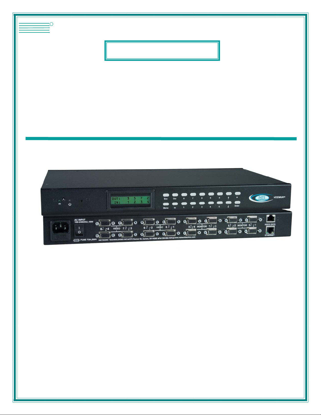
SM-nXm-15V-LC
Video Matrix Switch
Installation and Operation Manual
MAN156 Rev Date 4/26/2017
Page 2

TRADEMARK
VEEMUX is a registered trademark of Network Technologies Inc in the U.S. and other countries.
COPYRIGHT
Copyright © 1999-2017 by Network Technologies Inc. All rights reserved. No part of this publication may be reproduced, stored
in a retrieval system, or transmitted, in any form or by any means, electronic, mechanical, photocopying, recording, or otherwise,
without the prior written consent of Network Technologies Inc, 1275 Danner Drive, Aurora, Ohio 44202.
CHANGES
The material in this guide is for information only and is subject to change without notice. Network Technologies Inc reserves the
right to make changes in the product design without reservation and without notification to its users.
FIRMWARE VERSIONS
Firmware Version 1.0
i
Page 3

TABLE OF CONTENTS
Introduction....................................................................................................................................................................1
Basic Operation ...........................................................................................................................................................1
Supported Web Browsers............................................................................................................................................1
Ordering Information....................................................................................................................................................1
SM-nXm-15V-LC.......................................................................................................................................................1
Materials ......................................................................................................................................................................2
Cables..........................................................................................................................................................................2
Default User Name and Passwords ............................................................................................................................2
Features and Functions................................................................................................................................................3
Installation......................................................................................................................................................................4
To Mount to a Rack .....................................................................................................................................................4
Connect the Sources and Monitors.............................................................................................................................5
Connect RS232 ...........................................................................................................................................................6
Connect to the Ethernet...............................................................................................................................................6
Power Up.....................................................................................................................................................................7
Control Options.............................................................................................................................................................8
Front Panel LCD with Keypad Control.........................................................................................................................8
LCD Menus............................................................................................................................................................9
Save and Load (Recall) Config..............................................................................................................................9
RS232 Control...........................................................................................................................................................10
Remote Connection...................................................................................................................................................10
Baud Rate............................................................................................................................................................10
Unit Address and Loop Back...............................................................................................................................10
Command Protocol.................................................................................................................................................12
Autostatus............................................................................................................................................................13
NTI Switch Control Program For Windows 9X, NT, 2000, XP, Vista and 7 ..............................................................13
SerTest- RS232 Interface Test Program...................................................................................................................14
Main Options...........................................................................................................................................................14
Matrix Operations....................................................................................................................................................14
Ethernet Operations................................................................................................................................................14
Setup Options.........................................................................................................................................................15
Ethernet Control..........................................................................................................................................................16
Telnet Interface-Port 2000.........................................................................................................................................16
Telnet Interface-Port 2005.........................................................................................................................................17
Command Summary...............................................................................................................................................17
Command Detail.....................................................................................................................................................18
RU-Read Unit Size..............................................................................................................................................18
RO-Read Connection for Output Port .................................................................................................................18
CS- Connect Output Port to Input Port................................................................................................................18
CA- Connect All Output Ports to Input Port.........................................................................................................18
SS_01- Enable Auto Status Mode.......................................................................................................................19
SS_00- Disable Auto Status Mode......................................................................................................................19
SX- Examine connections ...................................................................................................................................19
Terminate telnet session .....................................................................................................................................20
Web Interface ............................................................................................................................................................21
Enter the Password ................................................................................................................................................21
Video Switch Page..................................................................................................................................................22
Administration.........................................................................................................................................................24
System Configuration..........................................................................................................................................24
Network Configuration.........................................................................................................................................25
Video Input Names..............................................................................................................................................26
Video Output Names...........................................................................................................................................27
Scanning Sequences...........................................................................................................................................28
Change Password...............................................................................................................................................30
Update Firmware.................................................................................................................................................31
Standby Mode .....................................................................................................................................................32
Logout..................................................................................................................................................................32
ii
Page 4

Support................................................................................................................................................................33
Reboot.................................................................................................................................................................33
Device Discovery Tool................................................................................................................................................34
Infrared Remote Control.............................................................................................................................................35
Materials ....................................................................................................................................................................35
Buttons.......................................................................................................................................................................36
Operation...................................................................................................................................................................37
Changing Ports.......................................................................................................................................................37
Channel Surfing...................................................................................................................................................37
Jump To Input......................................................................................................................................................38
Jump To Output...................................................................................................................................................38
Connect All ..........................................................................................................................................................38
Save and Recall......................................................................................................................................................38
Multiple Switch Control...........................................................................................................................................39
Canceling a Command...........................................................................................................................................39
Technical Specifications For IRT-UNV......................................................................................................................39
Troubleshooting the IRT-UNV ...................................................................................................................................39
RS232 Connection Cable............................................................................................................................................40
Pinout for Matrix Y-1 Cable........................................................................................................................................40
Specifications..............................................................................................................................................................40
Troubleshooting..........................................................................................................................................................41
Safety Statements .......................................................................................................................................................41
Index.............................................................................................................................................................................41
Warranty Information..................................................................................................................................................42
TABLE OF FIGURES
Figure 1- Secure rack mount ears to switch.......................................................................................................................................4
Figure 2- Secure switch to a rack ......................................................................................................................................................4
Figure 3- Install Video Source Cables................................................................................................................................................ 5
Figure 4- Connect a monitor to the VEEMUX....................................................................................................................................5
Figure 5- Connect user terminal for RS232 control............................................................................................................................6
Figure 6- Connect the LAN to the VEEMUX......................................................................................................................................6
Figure 7- Connect Power to VEEMUX...............................................................................................................................................7
Figure 8- RS232 connection with Matrix-Y-1 cable..........................................................................................................................11
Figure 9- Pinout of Matrix-Y-1 cable................................................................................................................................................11
Figure 10- Web interface Login page..............................................................................................................................................21
Figure 11- Main menu and Video Switch page................................................................................................................................22
Figure 12- System Configuration page ............................................................................................................................................24
Figure 13- Network Configuration page...........................................................................................................................................25
Figure 14- Video Input Names page................................................................................................................................................26
Figure 15- Video Output Names page.............................................................................................................................................27
Figure 16- Scanning Sequence page ..............................................................................................................................................28
Figure 17- Change Password page .................................................................................................................................................30
Figure 18- Update Firmware page...................................................................................................................................................31
Figure 19- VEEMUX in Standby Mode.............................................................................................................................................32
Figure 20- Logout of the VEEMUX web interface............................................................................................................................32
Figure 21- Support Tab....................................................................................................................................................................33
Figure 22- System Reboot...............................................................................................................................................................33
Figure 23- Device Discovery Tool page...........................................................................................................................................34
iii
Page 5

NTI VEEMUX VIDEO MATRIX SWITCH
INTRODUCTION
The SM-nXm-15V-LC (n = number of inputs (video sources), m = number of outputs (monitors)) video matrix switch (VEEMUX)
allows any of up to 8 video sources to output to any or all of up 8 (8) monitors. The configuration of the VEEMUX is determined
at time of order. The bandwidth of the SM-nXm-15V-LC is 160MHz and video resolutions through 1920 x1200 are supported with
no degradation. The switch can be controlled with the Front Panel Keypad, RS232 interface, Ethernet, or an Infrared Remote.
The VEEMUX can be ordered in many sizes and with several control options. The base unit includes a user keypad, an RS232
port, and an Ethernet port to make up a complete system. Built-in infrared control allows for maximum user satisfaction in each
unique configuration.
Basic Operation
The VEEMUX allows any source to be connected to any destination at any time with no restrictions or limitations.
Video inputs accept any RGBHV, RGBS, or RGsB signal.
Video outputs are compatible with any RGBHV or RGBS monitor, regardless of input. (RGsB monitor requires
RGsB input)
Supported Web Browsers
Most modern web browsers should be supported. The following browsers have been te sted:
Microsoft Internet Explorer 6.0 or higher
Netscape 7.0 or higher
Mozilla FireFox 0.9.2 or higher
Set your browser to always check if there is a newer version of the page than the version stored in cache. This action will ensure
that it will display the most up-to-date information.
Ordering Information
The SM-nXm-15V-LC is built to a specific size ranging from 2, 4 or 8 monitors and 4 to 8 video sources. The “n” in the part
number represents the number of video sources. Select a switch built for 4 or 8 video sources. The “m” in the part number
represents the number of outputs (monitors). A switch built for 2, 4 or 8 monitors may be ordered. It is not necessary to fully
populate all of the connectors on the unit (ex. an SM-8x8 switch has the capability of supporting 8 video sources and 8 monitors,
but it will operate with only 4 video sources with 2 monitors connected.
SM-nXm-15V-LC
Replace the “n” with 4 or 8
Replace the “m” with either 2, 4 or 8
The following list represents the available sizes that can be ordered:
SM-4x2-15V-LC SM-8x2-15V-LC
SM-4x4-15V-LC SM-8x4-15V-LC
SM-8x8-15V-LC
1
Page 6
NTI VEEMUX VIDEO MATRIX SWITCH
Materials
Materials Supplied with this kit:
NTI SM-nXm-15V-LC Video Matrix switch
IEC Line cord, country specific
Infrared Remote Control with 2-AAA batteries
CT6182 DB9 Female-to-RJ45 Female adapter
CB5021- 5 foot CAT5e-SF-5-Gray patch cable
4-#10-32 x 3/4" pan head screws and 10-32 cagenuts (server cabinet mounting hardware)
Rack Ear Kit including 2 Rack Ears and 6-#6-32 X 3/16” screws
Cables
All cables are sold separately. The following tables list the available stocked cables with thei r length in feet. All VGA input and
output connectors on Matrix Switches are FEMALE. When using multi-coax high resolution VGA to BNC cables, the BNC
connectors are also FEMALE for input and output. Custom cables are available – contact NTI for pricing and distance / resolution
limitations.
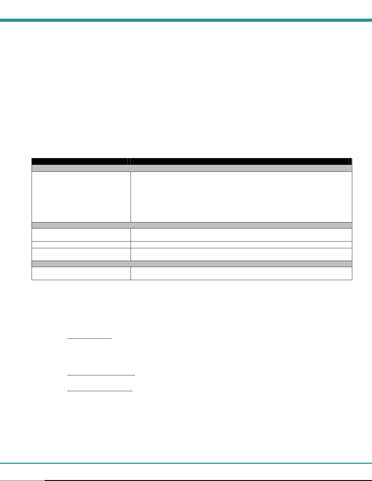
NTI NAME DESCRIPTION
VGA
VEXT-3/6/10/15/25/35/50/75/100-MM
VEXT-3/6/10/15/25/35/50/75/100
VINT-5B-6
Matrix-Y-1 or see page 31 for
alternative cables
CT6182 RJ45F-DB9M Adapter
Contact NTI for various lengths and
colors
Contact NTI for various lengths and
colors
Multi-coax high resolution VGA or SVGA video cable. Connectors are 15HD male-male
(used for INPUTS)- 3 thru 100 feet
Multi-coax high resolution VGA or SVGA video cable. Connectors are 15HD malefemale (used for OUTPUTS)-3 thru 100 feet
Multi-coax high resolution VGA to BNC cable. Connectors are 15HD male to 5 BNC’s-6
feet long
RS232
RS232 Interface Cable- Connectors are 9D male- female-female 12" long
Cat5 UTP Cable- Connectors are RJ45 male-Stocked cables are 2 thru 100 feet
Custom cables must have RJ45 connectors wired straight thru- pin 1 to pin 1, etc.
ETHERNET
Cat5 UTP Cable- Connectors are RJ45 male-Stocked cables are 2 thru 100 feet
Custom cables must have RJ45 connectors wired straight thru- pin 1 to pin 1, etc.
Default User Name and Passwords
The default Telnet password is nti (lower case letters only) . For instruction on using Telnet, see page 16.
(No username is required in order to use Telnet. You will only be prompted for a password.)
The default Web Interface user name
The default Web Interface password
see page 21.
is root (lower case letters only).
is nti (lower case letters only). For instruction on using the Web Interface,
2
Page 7
NTI VEEMUX VIDEO MATRIX SWITCH
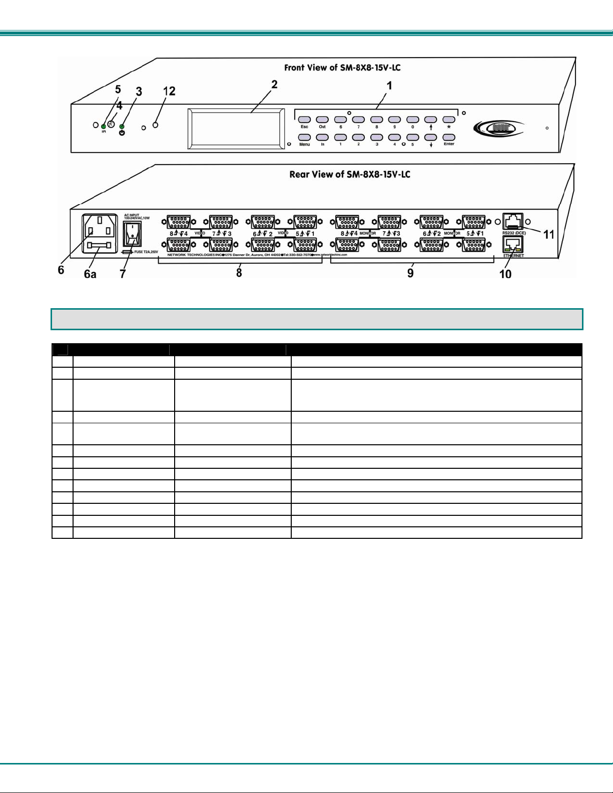
FEATURES AND FUNCTIONS
#
LABEL CONNECTOR/LED DESCRIPTION
Menu Buttons Buttons for navigating LCD menu
1
None LCD Display Displays port connections and menu for control of the VEEMUX
2
PWR Green/Red LED Illuminates green to indicate proper power to the unit and normal
3
operation
Illuminates red during system boot-up or while in standby
IR In Sensor Receives communication from hand-held remote control
4
IR Activity Green LED Illuminates to indicate communication between the hand-held remote
5
control and the VEEMUX
AC INPUT IEC Connector For attachment of the IEC power cord to power the VEEMUX
6
Fuse Fuseholder For replaceable 2A 240VAC Fast-blo Fuse
6a
None Power Switch For powering ON and OFF the VEEMUX
7
VIDEO HD15 Female For direct connection of VGA video cable from video source
8
MONITOR HD15 Female For direct connection of VGA video cable from display device
9
ETHERNET RJ45 Female For connection to an Ethernet for remote multi-user control
10
RS232 RJ45 Female For connection of a PC for serial control
11
System Reset Button Press to reset VEEMUX to default settings
12
3
Page 8
NTI VEEMUX VIDEO MATRIX SWITCH
INSTALLATION
To Mount to a Rack
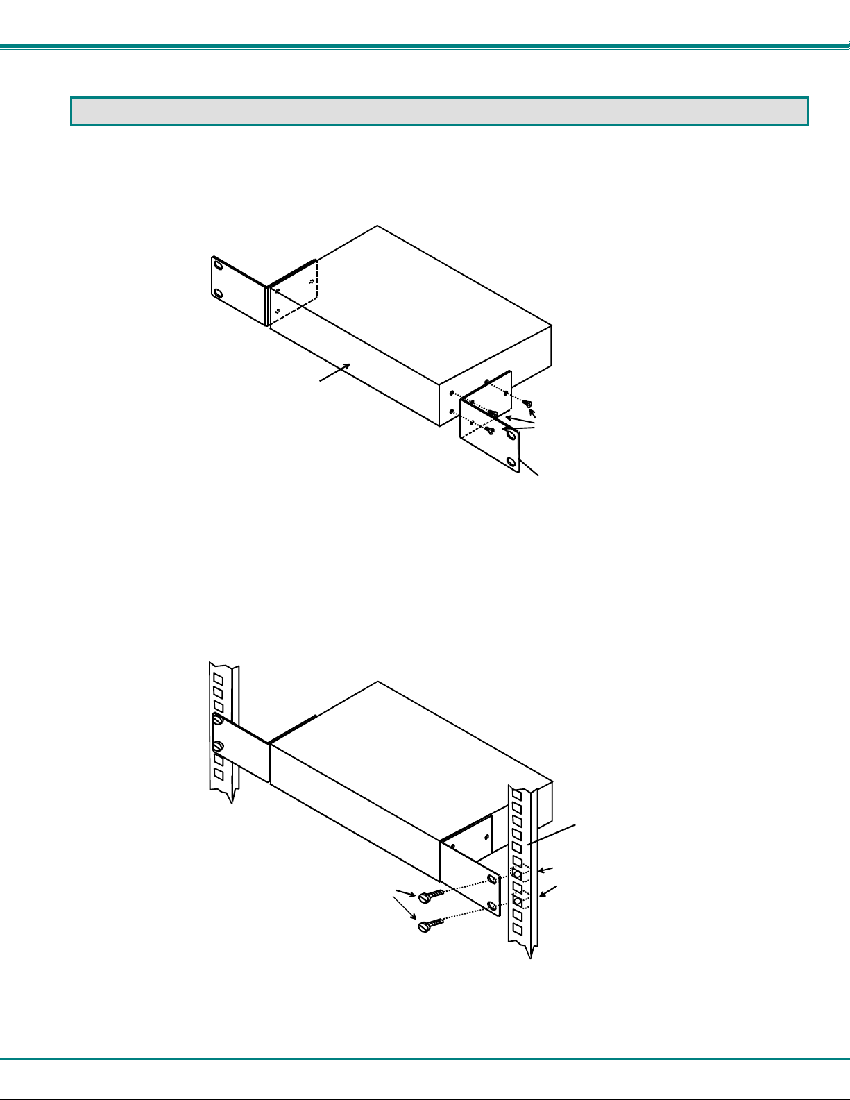
1. Attach the ears to the switch using the #6-32x3/16" flat Phillips-head screws (6) provided as shown in the illustration b elow.
The holes in the ears should line up with pre-threaded holes in the sides of the NTI switch. Tighten the screws securely.
Front of Switch
Figure 1- Secure rack mount ears to switch
2. Install 4 cage nuts (supplied) to the rack in locations that line up with the holes in the mounting ear on the NTI switch.
3. Secure the NTI switch to the rack using four #10-32X3/4” screws (supplied). Each screw should be of sufficient length
to go completely through the NTI mounting ear, rack frame and fully engage all threads in the cage nut. Be sure to
tighten all mounting screws securely.
4. Attach all cables securely to the switch and where necessary supply adequate means of strain relief for cables.
#10-32x3/4"
Rack Screws
(supplied)
NTI Switch
6-32x3/16"
Flat Head
Screws
(supplied)
Rack mount ear
NTI Switc h
Rack
Cage Nuts
(supplied)
Figure 2- Secure switch to a rack
4
Page 9
NTI VEEMUX VIDEO MATRIX SWITCH
Connect the Sources and Monitors
1. Turn OFF power to all video sources (inputs) that will be connected to the VEEMUX before connecting or
disconnecting any cables.
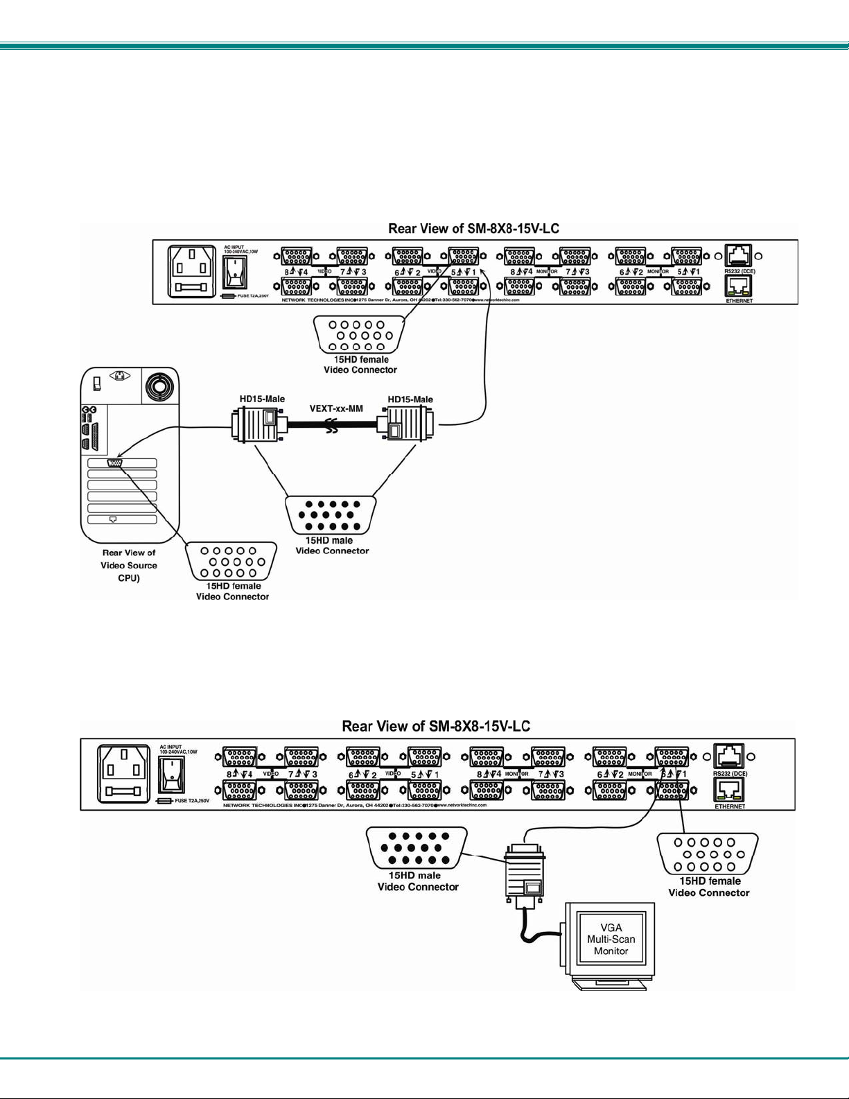
2. Connect a VEXT-xx-MM cable from the video port of a video source to a 15HD female video connector
labeled VIDEO 1 on the VEEMUX. (See Fig. 1)
3. Connect additional video sources to remaining 15HD female VIDEO x connectors as desired.
Figure 3- Install Video Source Cables
4. Connect a monitor to the 15HD female connector labeled MONITOR 1 on the rear of the VEEMUX (See Fig. 2).
5. Connect additional monitors to remaining 15HD female MONITOR x connectors as desired.
Figure 4- Connect a monitor to the VEEMUX
5
Page 10
NTI VEEMUX VIDEO MATRIX SWITCH
Connect RS232
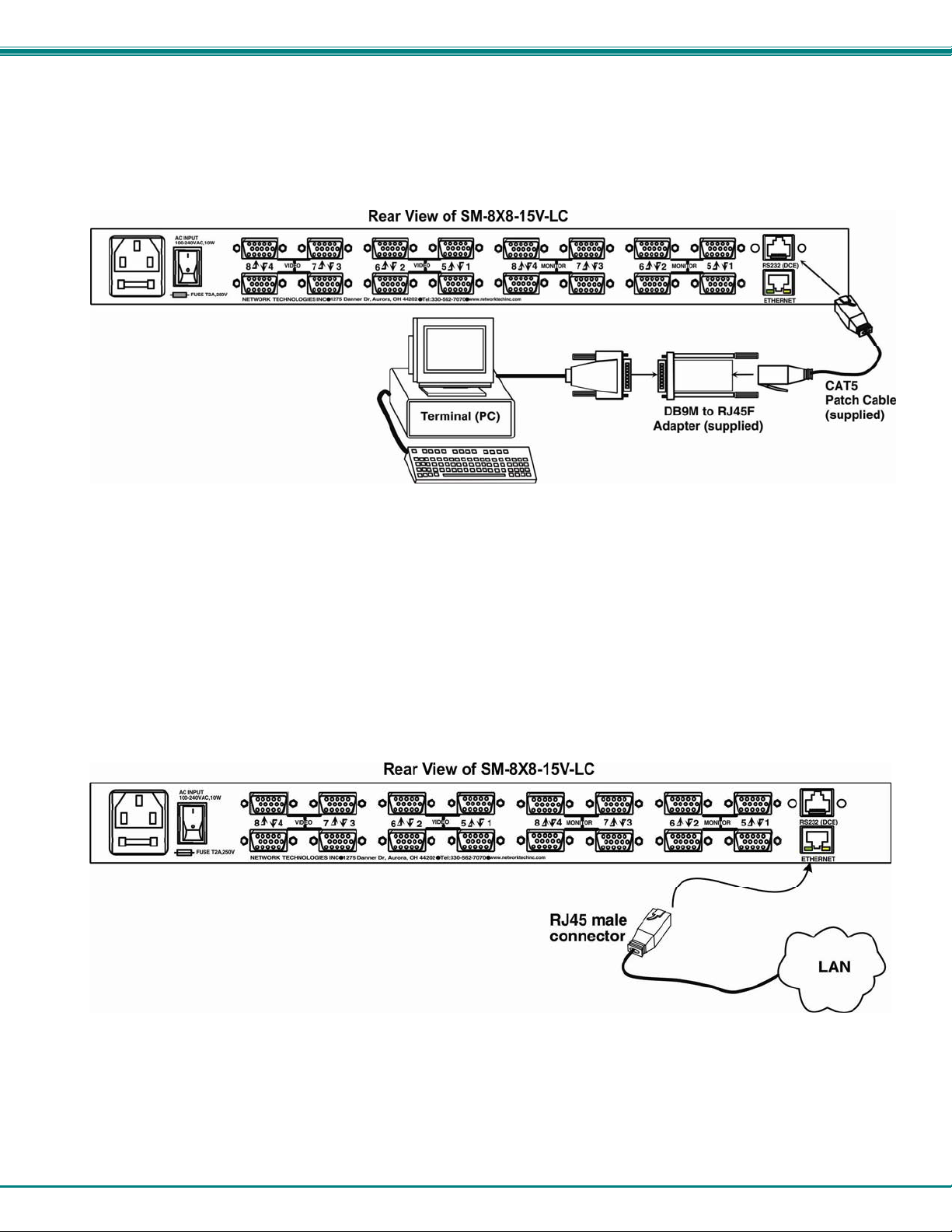
RS232 control can be achieved using a separate user terminal or CPU with a termina l program. To make a terminal connection, a
DB9M-to-RJ45F adapter and 5 foot CAT5 patch cable have been supplied if needed.
Figure 5- Connect user terminal for RS232 control
Connect to the Ethernet
If the Telnet Interface (page 16) or Web Interface (page 21) will be used, an Ethernet connection to the Local Area Network (LAN)
must be made using CAT 5 cable with RJ45 connectors. Wiring between the connectors should be straight through (pin 1 to pin
1, pin 2 to pin 2, etc.) Connect a CAT 5 cable between the connector label "ETHERNET" and the LAN (see Fig. 4).
Figure 6- Connect the LAN to the VEEMUX
6
Page 11
NTI VEEMUX VIDEO MATRIX SWITCH
Power Up
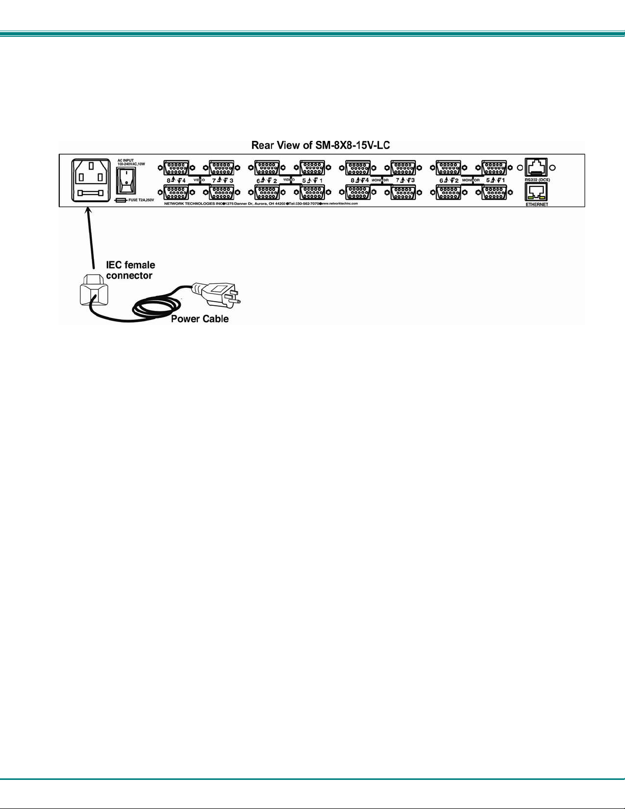
1. Plug the VEEMUX into an AC power outlet.
2. Turn ON power to the VEEMUX.
3. Turn ON power to the video sources and monitors connected to the VEEMUX.
Figure 7- Connect Power to VEEMUX
7
Page 12
NTI VEEMUX VIDEO MATRIX SWITCH
CONTROL OPTIONS
The VEEMUX video matrix switch has four methods of control:
Front Panel LCD with Keypad
Directly via an RS232 Interface
Remotely via Ethernet
Infrared Remote.
Every unit comes standard with the Front Panel LCD with Keypad, RS232, and Infrared Receiver built in. With the RS232 option,
there are no external devices to be purchased. NTI provides software commands as well as a test program to ensure the RS232
functions properly (see page 10 – RS232 Control).
Front Panel LCD with Keypad Control
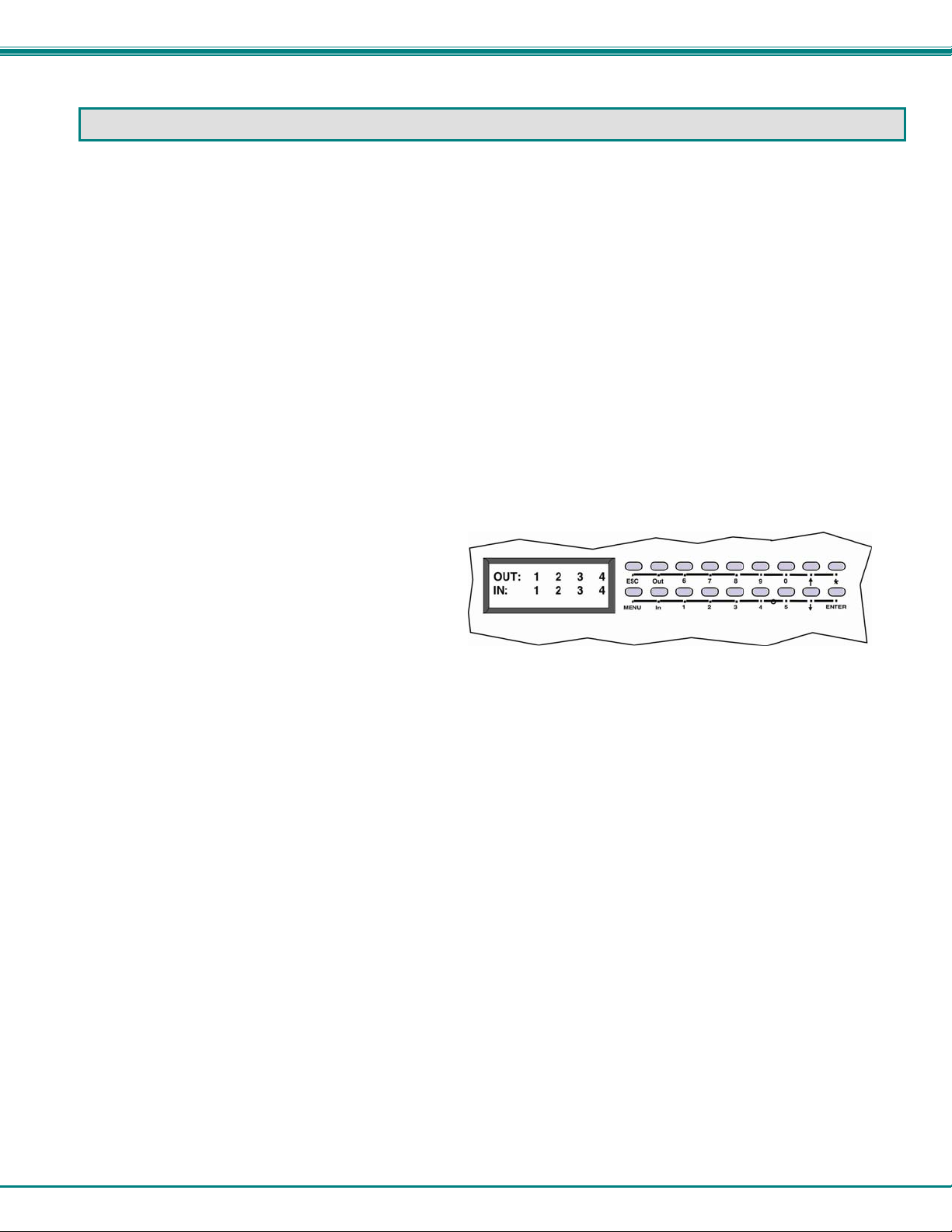
The front panel LCD and keypad allow the user to monitor switch status and route any user to any video source on the switch.
When the unit is powered up, each monitor is automatically connected to the video sourc e of its equa l number (i.e. monitor 1 to
source 1, monitor 2 to source 2, monitor 3 to source 3, etc.). Along with the routing of the inputs (video sources) to the outputs
(monitors) the keypad and LCD allow the users to configure the RS-232 control interface. The keypad buttons perform the
following functions.
ESC Escape back to the main display.
0 – 9 Used to enter numbers. ( # )
OUT Precedes the output number
IN Used following single digit output entries
ENTER Used following single digit entries and
to select menu options
Display next 4 outputs and their inputs
Display previous 4 outputs and their inputs
MENU See below for description of the Menu.
* Connects all outputs to one input (i.e. To set all outputs to one input ( * ) + (Input # ) + (ENTER) )
To configure the VEEMUX, use the Menu keys.
Press the List button to list your main menu options:
1- Serial
2- Ethernet
3- Standby
4- Save Config
5- Load Config
Use the Up and Down Arrow keys to scroll through this list.
Use the Enter Key to select a menu item.
Press the Menu button again to exit the menu.
If, while in a menu, you pause for more than 5 seconds, you will automatically exit the menu.
8
Page 13

NTI VEEMUX VIDEO MATRIX SWITCH
LCD Menus
1. Under the “Serial” menu are two parameters:
1- Baud rate
2- Address
These parameters are used when the VEEMUX is controlled through an RS232 connection (page 1 0). If you select Baud rate,
use the arrow keys to toggle through the available baud rates. The baud rate can be set to 115200, 57600, 38400, 19 200, 9600,
4800, 2400, or 1200.
If you select Address, use the arrow keys to toggle through the address options (01-15). This is also the switch address used in
conjunction with the IR Remote operation (page 39).
2. Under “Ethernet” menu are several parameters:
1- Mode
2- IP
3- Mask
4- Gateway
5- Primary DNS
6- Alt. DNS
The Mode parameter will let you select between a manual IP setting (“Static”) and a “DHCP” assigned dynamic IP address setting.
An asterisk indicates which mode is configured, an arrow shows which mode is being selected. To cha nge the configured setting
and move the asterisk, select the desired mode and press the Enter button.
If you choose a manual IP setting, the IP parameter provides the fields for entering a valid IP address. Use the up and down
arrows to advance the numbers, and the Enter button to move from field to field. Press Menu to exit this screen.
Selections 3, 4 are necessary to apply valid values for your Subnet Mask and Gateway. Navigate these settings as described for
setting the IP address.
Selections 5 and 6 are not used at this time and are therefore unnecessary.
3. The third option in the main menu is ”Standby”. If you select Standby, the VEEMUX switch will immediately go into a power
saver mode and the LCD display will go blank. It will remain in this state until
1) any button is pressed on the front panel,
2) the Standby button is pressed on the IR Remote Control (page 36), or
3) the “Disable Standby” button is pressed in the web interface (page 32)
Save and Load (Recall) Config
The VEEMUX provides the ability to save and recall up to 100 switch configurations using the LCD menu. The switch
configurations define the current port connections and video blank status.
Note: The Remote Control can also be used to access these configurations by using the “SAVE” and “RECALL”
buttons.
To save a configuration, select “Save Config” from the main menu followed by a numeric button(s) (0-99) corresponding to
the memory slot the configuration is to be saved in. Press Enter after your selection to force the current configuration to
immediately be saved to the selected memory slot.
Configurations can be loaded (recalled) in much the same manner. To recall, select “Load Config” fro m the main menu
followed by the numeric button(s) (0-99) corresponding to the memory slot from which the configuration is to be recalled. Press
Enter after your selection to immediately force the switch to change the current switch configuration to match that of the
configuration recalled.
Configurations that are saved into memory locations via
the keypad can be recalled via the web interface (page 22)
and vice versa.
9
Page 14
NTI VEEMUX VIDEO MATRIX SWITCH
RS232 Control
RS232 enables the VEEMUX to be remotely controlled via RS232. To control the VEEMUX via RS232 the user has three
options:
write a program that runs on a PC using the Command Protocol (page 12)
use the NTI Switch Control Program (page 13) downloaded from http://www.networktechinc.com/download/d-
vmtx.html
use the SerTest program (page 14) provided with the NTI Switch Control Program download
Remote Connection
The RS232 Interface is designed to meet the RS232C standard and can be controlled from any CPU or other contro ller with an
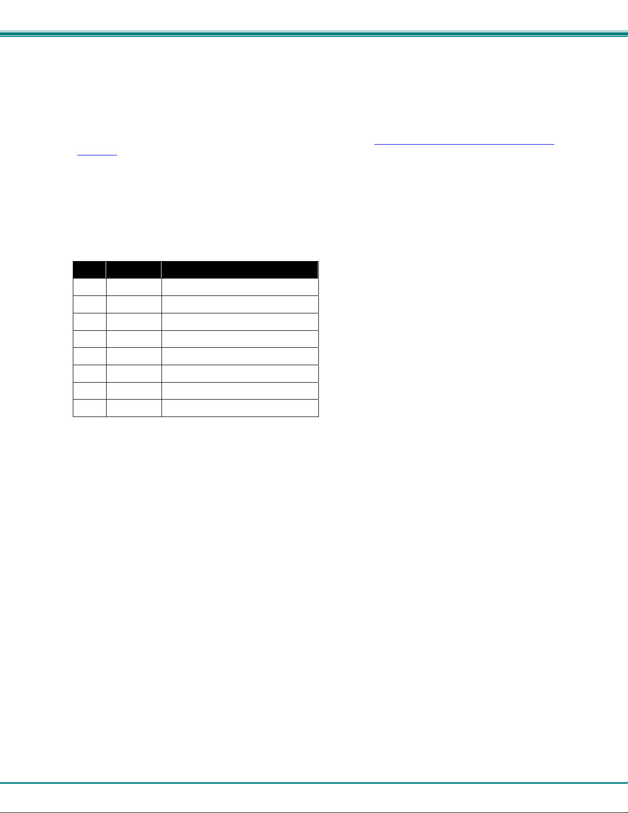
RS232 communications port. The pin-out for the RJ45 connector on the unit is as follows:
RS232 (RJ45) CONNECTOR
PIN SIGNAL FUNCTION
1 - No connection
2 - No connection
3 RX+ Receive data (TXD at host)
4 GND Ground
5 - No connection
6 TX+ Transmit data (RXD at host)
7 - No connection
8 - No connection
A 5 foot patch cable and adapter, RJ45-to-DB9, have been provided for connection to most CPUs (see page 6). To daisy chain
multiple units, connect a Matrix-Y-1 cable (sold separately) between the CPU and the first switch, and between each switch (as
shown in Figure 8).
Baud Rate
The baud rate can be changed by selecting MENU on the front panel ke ypad, using Telnet commands (page 16) or from the
RS232 commands (page 12). The baud rate can be set to 115200, 57600, 38400, 19200, 9600, 4800, 24 00, or 1200. A data
protocol of 8 data bits, no parity, and 1 stop bit is used for communications. The default baud rate setting is 9600.
Unit Address and Loop Back
To allow multiple units to be controlled from a single host port, the RS232 control interface is designed to allow "daisy chaining" up
to 15 units using an NTI Matrix-Y-1 cable. Connect the Matrix-Y-1 cable between the RJ45-to-DB9 serial adapter (pro vided with
the RS232 option) and the CPU as shown in Figure 8. By
unique address (1-15). Then the unit will only respond to commands on the bus if its address is embedded in the command.
setting the appropriate unit address (page 9), each unit can be given a
10
 Loading...