

NTE NTE5610, NTE5609, NTE5608 Datasheet
NTE5608 thru NTE5610
TRIAC
8 Amp
Description:
The NTE5608 through NTE5610 series of TRIACs are high performance glass passivated PNPN
devices i n a TO220 t ype package designed for g ener al purpose a ppl icati ons where moderate gate
sensitivity is required.
Absolute Maximum Ratings: (TA = +25°C unless otherwise specified)
Repetitive Peak Off–State Voltage (TJ = –40° to +125°C, RGK = 1kΩ), V
NTE5608 400V. . . . . . . . . . . . . . . . . . . . . . . . . . . . . . . . . . . . . . . . . . . . . . . . . . . . . . . . . . . . . . . . . . .
NTE5609 600V. . . . . . . . . . . . . . . . . . . . . . . . . . . . . . . . . . . . . . . . . . . . . . . . . . . . . . . . . . . . . . . . . . .
NTE5610 800V. . . . . . . . . . . . . . . . . . . . . . . . . . . . . . . . . . . . . . . . . . . . . . . . . . . . . . . . . . . . . . . . . . .
On–State Current (All Conduction Angles, TC = +85°C), I
Non–Repetitive On–State Current (Half Cycle), I
TSM
T(RMS)
60Hz 77A. . . . . . . . . . . . . . . . . . . . . . . . . . . . . . . . . . . . . . . . . . . . . . . . . . . . . . . . . . . . . . . . . . . . . . .
50Hz 70A. . . . . . . . . . . . . . . . . . . . . . . . . . . . . . . . . . . . . . . . . . . . . . . . . . . . . . . . . . . . . . . . . . . . . . .
Fusing Current (t = 10ms), I2t 24A2s. . . . . . . . . . . . . . . . . . . . . . . . . . . . . . . . . . . . . . . . . . . . . . . . . . . . . .
Peak Gate Current (t = 10µs Max), I
Peak Gate Dissipation (t = 10µs Max), P
Gate Dissipation (t = 20ms Max), P
Operating Junction Temperature Range, T
Storage Temperature Range, T
Thermal Resistance, Junction–to–Case, R
Thermal Resistance, Junction–to–Ambient, R
GM
GM
G(AV)
J
stg
thJC
thJA
Lead Temperature (During Soldering, 1.6mm from case, 10sec max), T
DRM
L
8A. . . . . . . . . . . . . . . . . . . . . . . . . . .
4A. . . . . . . . . . . . . . . . . . . . . . . . . . . . . . . . . . . . . . . . . . . . . . . . .
10W. . . . . . . . . . . . . . . . . . . . . . . . . . . . . . . . . . . . . . . . . . .
1W. . . . . . . . . . . . . . . . . . . . . . . . . . . . . . . . . . . . . . . . . . . . . . .
–40° to +125°C. . . . . . . . . . . . . . . . . . . . . . . . . . . . . . . . . .
–40° to +125°C. . . . . . . . . . . . . . . . . . . . . . . . . . . . . . . . . . . . . . . . . .
3K/W. . . . . . . . . . . . . . . . . . . . . . . . . . . . . . . . . . . . . . . .
60K/W. . . . . . . . . . . . . . . . . . . . . . . . . . . . . . . . . . . .
+250°C. . . . . . . . . . . . . . .
Electrical Characteristics: (TA = +25°C unless otherwise specified)
Parameter Symbol Test Conditions Min Typ Max Unit
Off–State Leakage Current I
On–State Voltage V
On–State Threshold Voltage V
On–State Slope Resistance r
DRM
T(TO)
VD = V
VD = V
IT = 12A, TJ = +25°C – – 1.85 V
T
TJ = +125°C – – 1 V
TJ = +125°C – – 80 mΩ
T
, RGK = 1kΩ, TJ = +25°C – – 5 µA
DRM
, RGK = 1kΩ, TJ = +125°C – – 2 mA
DRM
Electrical Characteristics (Cont’d): (TA = +25°C unless otherwise specified)
Parameter Symbol Test Conditions Min Typ Max Unit
Gate Trigger Current I
Gate Trigger Voltage V
GT
GT
Holding Current I
Critical Rate–of–Rise dv/dt VD = 0.67 x V
VD = 12V, Note 1 – – 10 mA
VD = 12V, All Quadrants – – 2.5 V
RGK = 1kΩ – – 10 mA
H
, RGK = 1kΩ, TJ = +1 25°C 50 – – V/µs
DRM
Critical Rate–of–Rise, Off–State dv/dtcIT = 8A, di/dt = 3.55A/ms, TC = +85°C 2 – – V/µs
Note 1. For either polarity of gate voltage with reference to electrode MT1.
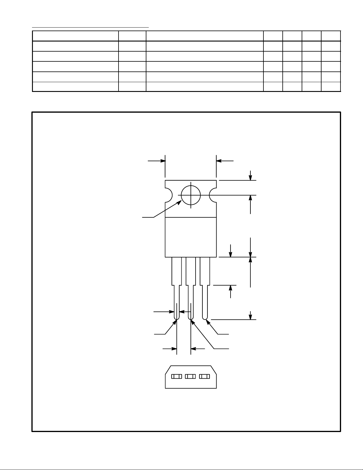
.420 (10.67)
Max
.110 (2.79)
MT
2
.147 (3.75)
Dia Max
.500
(12.7)
Max
.070 (1.78) Max
MT
.100 (2.54)
.250 (6.35)
Max
.500
(12.7)
Min
1
Gate
MT
2
 Loading...