

NTE NTE5586 Datasheet

NTE5586 & NTE5588
Silicon Controlled Rectifier
for Phase Control Applications
Electrical Characteristics: (Maximum values @ TJ = +125°C unless otherwise specified)
Repetitive Peak Voltages, V
NTE5586 600V. . . . . . . . . . . . . . . . . . . . . . . . . . . . . . . . . . . . . . . . . . . . . . . . . . . . . . . . . . . . . . . . . . .
NTE5588 1600V. . . . . . . . . . . . . . . . . . . . . . . . . . . . . . . . . . . . . . . . . . . . . . . . . . . . . . . . . . . . . . . . . .
Non–Repetitive Peak Off–State Voltage, V
NTE5586 600V. . . . . . . . . . . . . . . . . . . . . . . . . . . . . . . . . . . . . . . . . . . . . . . . . . . . . . . . . . . . . . . . . . .
NTE5588 1600V. . . . . . . . . . . . . . . . . . . . . . . . . . . . . . . . . . . . . . . . . . . . . . . . . . . . . . . . . . . . . . . . . .
Non–Repetitive Peak Reverse Blocking Voltage, V
NTE5586 700V. . . . . . . . . . . . . . . . . . . . . . . . . . . . . . . . . . . . . . . . . . . . . . . . . . . . . . . . . . . . . . . . . . .
NTE5588 1700V. . . . . . . . . . . . . . . . . . . . . . . . . . . . . . . . . . . . . . . . . . . . . . . . . . . . . . . . . . . . . . . . . .
Average On–State Current (Half Sine Wave, T
RMS On–State Current, I
(RMS)
Continuous On–State Current, I
Peak One–Cycle, Non–Repetitive Surge Current (10ms Duration), I
60% V
reapplied 4650A. . . . . . . . . . . . . . . . . . . . . . . . . . . . . . . . . . . . . . . . . . . . . . . . . . . . . . . .
RRM
VR ≤ 10V 5120A. . . . . . . . . . . . . . . . . . . . . . . . . . . . . . . . . . . . . . . . . . . . . . . . . . . . . . . . . . . . . . . . . .
Maximum I
2
t for Fusing (VR ≤ 10V), I2t
10ms Duration 131,000A
10ms Duration 97350A
Peak Forward Gate Current (Anode Positive with Respect to Cathode), I
Peak Forward Gate Voltage (Anode Positive with Respect to Cathode), V
Peak Reverse Gate Voltage, V
Average Gate Power, P
G
Peak Gate Power (100µs Pulse Width), P
Rate of Rise of Off–State Voltage (To 80% V
Rate of Rise of ON–State Current, di/dt
(Gate Drive 20V, 20Ω, with t
Repetitive 500A/µs. . . . . . . . . . . . . . . . . . . . . . . . . . . . . . . . . . . . . . . . . . . . . . . . . . . . . . . . . . . .
Non–Repetitive 1000A/µs. . . . . . . . . . . . . . . . . . . . . . . . . . . . . . . . . . . . . . . . . . . . . . . . . . . . . .
Peak On–State Voltage (I
TM
Forward Conduction Threshold Voltage, V
Forward Conduction Slope Resistance, r 0.99mΩ. . . . . . . . . . . . . . . . . . . . . . . . . . . . . . . . . . . . . . . . . .
Repetitive Peak Off–State Current (At V
Repetitive Peak Reverse Current (At V
Maximum Gate Current Required to Fire All Devices (V
Maximum Gate Voltage Required to Fire All Devices (V
Maximum Holding (V
= 6V, IA = 2A, TJ = +25°C), I
A
Maximum Gate Voltage which will not Trigger any Device, V
& V
DRM
RRM
T
RGM
≤ 1µs, Anode Voltage ≤ 80% V
r
= 710A), V
TM
DRM
RRM
DSM
GM
O
), I
RSM
= +85°C), I
C
, Gate Open), dv/dt 200V/µs. . . . . . . . . . . . . . . . . .
DRM
), I
DRM
RRM
H
T(AV)
TSM
FGM
FGM
)
DRM
= 6V, IA = 2A, TJ = +25°C), I
A
= 6V, IA = 2A, TJ = +25°C), V
A
GD
GT
GT
226A. . . . . . . . . . . . . . . . . . . . . . . . .
355A. . . . . . . . . . . . . . . . . . . . . . . . . . . . . . . . . . . . . . . . . . . . . . . . . . . . . .
355A. . . . . . . . . . . . . . . . . . . . . . . . . . . . . . . . . . . . . . . . . . . . . . . . . . . .
2
sec. . . . . . . . . . . . . . . . . . . . . . . . . . . . . . . . . . . . . . . . . . . . . . . . . . . . . .
2
sec. . . . . . . . . . . . . . . . . . . . . . . . . . . . . . . . . . . . . . . . . . . . . . . . . . . . . . .
20A. . . . . . . . . . . . . . .
18V. . . . . . . . . . . . . .
5V. . . . . . . . . . . . . . . . . . . . . . . . . . . . . . . . . . . . . . . . . . . . . . . . . . . .
2W. . . . . . . . . . . . . . . . . . . . . . . . . . . . . . . . . . . . . . . . . . . . . . . . . . . . . . . . . . . .
100W. . . . . . . . . . . . . . . . . . . . . . . . . . . . . . . . . . . . . . . . .
1.62V. . . . . . . . . . . . . . . . . . . . . . . . . . . . . . . . . . . . . . . . . . .
0.92V. . . . . . . . . . . . . . . . . . . . . . . . . . . . . . . . . . . . . . . . . .
20mA. . . . . . . . . . . . . . . . . . . . . . . . . . . . . . . . . . .
20mA. . . . . . . . . . . . . . . . . . . . . . . . . . . . . . . . . . . .
150mA. .
3V. . . . .
600mA. . . . . . . . . . . . . . . . . . . . . . . . . . . . . . . . .
0.25V. . . . . . . . . . . . . . . . . . . . . . . . .
Electrical Characteristics (Cont’d): (Maximum values @ TJ = +125°C unless otherwise specified)
Operating Temperature Range, T
Storage Temperature Range, T
C
stg
Thermal Resistance, Junction–to–Case (VF = Max Rating), R
tnJC
–40° to +125°C. . . . . . . . . . . . . . . . . . . . . . . . . . . . . . . . . . . . . . . . .
–40° to +150°C. . . . . . . . . . . . . . . . . . . . . . . . . . . . . . . . . . . . . . . . . .
DC and 180° Sine wave 0.12°C/W. . . . . . . . . . . . . . . . . . . . . . . . . . . . . . . . . . . . . . . . . . . . . . . . . .
120° Rectangular wave 0.14°C/W. . . . . . . . . . . . . . . . . . . . . . . . . . . . . . . . . . . . . . . . . . . . . . . . . .
Thermal Resistance, Case–to–Heat Sink, R
thC–HS
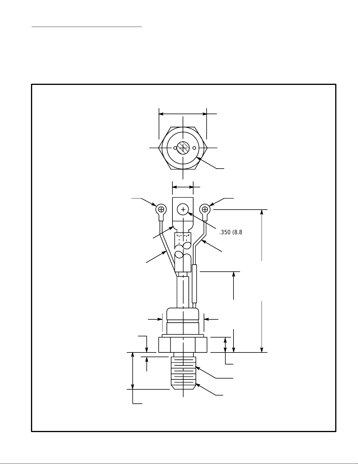
1.443 (36.68) Max
(Across Corners)
1.031 (26.18) Dia
(Ceramic)
.643 (16.35)
0.04°C/W. . . . . . . . . . . . . . . . . . . . . . . . . . . . . . . . .
Cathode
Cath-
ode
(Red)
1.212 (30.8)
Dia Max
.156 (3.96) Max
For No. 6 ScrewFor No. 6 Screw
.350 (8.89)
Dia Max
Gate
(White)
8.100
(205.74)
Max
(Terminals
1, 2, & 3)
3.625
(92.07)
Max
.630 (16.0)
1.077 (27.35) Max
3/4–16 UNF–2A
(Terminal 4)
Anode
 Loading...