

Page 1

Page 2

nStor Corporation, Inc.
© 1996-1998 nStor Corporation, Inc., All Rights Reserved.
3rd Edition
nStor Corporation, Inc. shall not be liable for any damages or for the loss of any information resulting from the
performance or use of the information contained herein. Your rights to the software are governed by the license
agreement included with any accompanying software. nStor Corporation reserves the right to periodically revise this
manual without notice.
Product features and specifications described are subject to change without notice.
This manual may not be reproduced in whole or part, without prior written permission from nStor Corporation, Inc.
nStor Corporation, Inc.
450 Technology Park
Lake Mary, Florida 32746
nStor, A dminiStor, Smart Cabinet, and the nStor logo are trademarks or r egister ed tr ademarks of nStor Corpor ation, Inc.
Other company and product names herein may be trademarks or registered trademarks of their respective
companies.
CAUTION:
ATTENTION:
NOTE:
Drives and controller/adapter cards described in this manual should only be installed in UL-listed
and CSA certified computers that give specific instructions on the installation and removal of
accessory cards (refer to your computer installation manual for proper instructions).
Les lecteurs et cartes contrôleurs décrits ici ne doivent être montés que sur des ordinateurs
homologués (UL et CSA) et livrés avec des manuels contenant les instructions d’installation et de
retrait des accessoires. Reportez-vous au manuel d’installation de votre ordinateur.
Only drives supplied by nStor Corporation are approved for use in this pr oduct. Use of other driv es
could affect the safety and/or radio frequency interference characteristics of the product.
Page 3

Regulatory Information
FCC Radio Frequency Interference Statement
This equipment has been tested and found to comply with the limits for a Class B digital device, pursuant to Part 15 of the
FCC rules. These limits are designed to provide reasonable protection against harmful interference in a residential
installation. This equipment generates, uses and can radiate radio frequency energy, and if not installed and used in
accordance with the instructions, may cause harmful interference to radio or tele vision communications. However , there is
no guarantee that the interference will not occur in a particular installation. If this equipment does cause harmful
interference to radio or television reception, which can be determined by turning the equipment off and on, the user is
encouraged to try to correct the interference by one or more of the following measures:
■
Reorient or relocate the receiving antenna.
Increase the separation between the equipment and receiver.
■
Connect the equipment to an outlet on a circuit other than that to which the receiver is connected.
■
■
Consult the dealer or an experienced radio/TV technician for help.
nStor Corporation, Inc. is not r esponsible for any interfer ence caused b y unauthorized modifications to this equipment. It is
the user’s responsibility to correct such interference. You are also warned, that any changes to this certified device will void
your legal right to operate it.
CAUTION:
ATTENTION:
Drives and controller/adapter cards described in this manual should only be installed in UL-listed and CSA
certified computers that give specific instructions on the installation and removal of accessory cards (refer
to your computer installation manual for proper instructions).
Les lecteurs et cartes contrôleurs décrits ici ne doivent être montés que sur des ordinateurs homologués (UL
et CSA) et livrés avec des manuels contenant les instructions d’installation et de retrait des accessoires.
Reportez-vous au manuel d’installation de votre ordinateur.
Compliance Information Statement
We
,
nStor Corporation, Inc.
450 Technology Park
Lake Mary, Florida 32746
(407) 829-3500
declare under our sole responsibility that the product,
Type of Equipment: Disk Array Enclosure
Model Number: CR8e
to which this declaration relates is in conformity with the Title 47 o f the US Code o f Federal Regulations, P art 15 co v ering Class B
personal computers and peripherals.
Operation is subject to the following two conditions:
1
This device may not cause harmful interference, and
2
This device must accept any interference received, including interference that may cause undesired operation.
Page 4

Power Cord Selection
■
This subsystem is intended for indoor use only.
This subsystem is intended to be plugged into a 6A branch circuit in Europe.
■
To select the proper power cord:
■
For 110 Volt Operation
– Use a UL Listed/CSA Labeled cord set consisting of a minimum 18 AWG, type SVT or
SJT three conductor cord, terminating in a molded connector body having an IEC CEE-22 female configuration on
one end and a molded-on parallel blade grounding type attachment plug rated 15A, 125V configuration (5 - 15P) at
the other end.
For 230 Volt Operation (North America)
– Use a UL Listed/CSA Labeled cord set consisting of a minimum 18
AWG, type SVT or SJT three conductor cord, terminating in a molded connector body having an IEC CEE-22
female configuration on one end and a molded-on tandem blade grounding type attachment plug rated 15A, 250V
configuration (6 - 15P) at the other end.
For 230 Volt Operation (Europe)
– Use a cord set marked “HAR”, consisting of a H05VV-F cord that has a
minimum 0.75 square mm diameter conductors provided with an IEC 320 receptacle and a male plug for the
country of installation rated 6A, 250V.
NOTE:
The subsystem automatically selects the proper settings for the input voltage. Therefore, no additional adjustments
are necessary to connect the unit to any input voltage within the range marked on the drive.
Das Laufwerk sollte nicht im Freien verwendet werden.
■
■
In Europa, sollte das Laufwerk an einen 6A-Stromkreis angeschlossen werden.
Zur Wahl des korrekten Netzkabels beachten Sie bitte folgendes:
■
230V-Betrieb (Europa)
– Verwenden Sie Netzkabel der Bezeichnung “HAR” die H05VV-F-Kabel und einen
Leitungsdurchmesser von mindestens 0,75 mm2 aufweisen. Ver Wenden Sie eine IEC 320-Buchse und einen für das
Installationsland passenden Stecker, der auf 6A und 250V gesichert ist.
Page 5

Contents
Preface
Welcome v
Features vi
Where to Find Answers vii
Registering Your Product vii
1 Getting Started
CR8e Subsystem at a Glance 2
Components 4
Hot Swap Disk Drives 4
Hot Swap Cooling Fans 4
Hot Swap Power Supplies 5
Power Switch 5
Door Lock 5
I/O Interface Card 6
Power Cord Connector and Fuse 6
Configuration Modules 7
Controlling and Monitoring 8
Operator Control Panel 8
LEDs 9
Alarm Speaker 11
Fault LEDs 11
SAF-TE Card 11
v
1
i
Page 6

2 Installation
Setup 13
System Requirements 14
Guidelines 14
Rack-Mount Subsystem Assembly 15
Component Installation 17
Cabling Configuration 20
General 20
Ultra Wide SCSI Mode 22
Fast Wide SCSI Mode 26
Other Configurations 36
13
3 Using the CR8e
Notifications and Error Conditions 37
Power-On Self Test 37
Firmware Error Conditions 38
LED Descriptions 39
Operator Control Panel 40
Startup Screens 40
Power Supply Error Conditions 41
Subsystem Status Icon 41
Main Menu 42
Options Menu 46
Heat Threshold 49
SAFTE CHAIN ID 50
Change Passcode 51
Unlock Options 52
4 Troubleshooting
Common Enclosure Problems 53
Common SCSI Bus Problems 54
Common Problems and Interpreting the LED Indications 56
37
53
5 Maintenance
Replacing a Disk Drive 57
Replacing a Power Supply 58
Replacing the Cooling Fans 60
Replacing an I/O Interface Card 61
ii
Contents
57
Page 7

Replacing a Fuse 62
Replacing the CR8e Cabinet 63
A Glossary
B Technical Information
Specifications 69
Connectors and Jumpers 70
Connectors 70
Jumpers 72
Index
65
69
77
Contents
iii
Page 8

iv
Contents
Page 9

Preface
Welcome
Congratulations on the purchase of your new CR8e from nStor Corporation.
The nStor CR8e provides a superior fault-tolerant network storage solution in a
subsystem-based SAF-TE compliant RAID enclosure.
The CR8e is an eight drive enclosure designed to support Ultra Wide SCSI
(Fast-20) and Fast Wide SCSI protocols. The Ultra Wide SCSI (Fast-20) support
maintains SCSI bus data transfer rates up to 40 Mbytes/sec. The subsystem
supports both host system based RAID controllers, as well as an option for an
onboard Ultra SCSI-to-SCSI RAID controller.
The CR8e also provides an upgrade path to Ultra2 Low Voltage Differential
(LVD) SCSI technology and easily connects to the network attach storage module
to maintain its total cost of ownership.
The intelligent enclosure is compliant with SAF-TE version 1.0, an industry
standard, non-proprietary means to automatically integrate with peripheral
packaging that supports status signals, hot swapping drives and enclosure
monitoring. Combined with the enterprise-wide storage management software
from nStor, additional levels of fault tolerance can be maintained.
v
Page 10

Preface
Features
The following are major features of the nStor CR8e disk array subsystem:
RAID Level Support
Configuration
Drive Support
Interface
Scalable Capacities
Hot Swap Power Supplies
Cooling
Notifications
Front Panel
RAID levels 0, 1, 3, 5, 10
Deskside tower-based subsystem or rack-mount
subsystem.
Up to eight 3.5-inch, half-height form factor, hot
swappable high performance 7,200 and 10,000 RPM
Ultra SCSI disk drives using SC A-II technology (4.2, 9.1,
or 18.2 gigabyte capacities).
Ultra SCSI (Fast 20)/SCSI.
Drive capacities are expandable to 145 GB using 18 GB
disk drives and further expansion through
daisy-chaining of multiple cabinets.
Dual hot swap power supplies expandable to three, all
with current sharing circuitry.
Dual high capacity hot swap cooling fans.
LEDs and audible alarms provide failure notifications.
A password protected Oper ator Control Panel (OCP) for
administration control and monitoring functions.
(1 + 0)
, 30, and 50.
SCSI-to-SCSI Support
Termination
Locking Door
SAF-TE
Cluster-Ready
Storage Management Solution
vi
Features
Provides on-board Ultra SCSI-to-Ultra SCSI RAID
processing via the Ultra S2S RAID Controller.
Automatic SCSI-bus termination.
A key-locking front door.
SAF-TE v1.0 compliant enclosure.
Cluster-ready subsystem.
Enterprise-wide managing and monitoring using
AdminiStor Manager and AdminiStor Agent software.
Page 11

Preface
Where to Find Answers
When you have questions about your nStor products there are several places you
can look to find answers. Refer to the following:
In this guide
Resource Guide
AdminiStor Manager User’s Guide
AdminiStor Agent User’s Guide
On the software diskettes
Via email
This user’s guide provides detailed information for
installing and using the CR8e
manual assumes that the reader is already familiar with the
operating system environments where the CR8e will be
installed.
Use this manual to locate telephone numbers for customer
service and technical support, technical support email
address, instructions to obtain an RMA number, and
conditions of the limited warranty.
Use this manual to install and use the nStor Java-based
management and monitoring software.
Use one of these manuals to install and use the nStor
SNMP-based network RAID subsystem management
software.
Review the README files for last minute information
about the release of the software products.
You may email questions and comments to
[email protected].
disk array subsystem. The
Registering Your Product
Registering your product allows nStor to continue providing the highest quality
technical support while keeping you informed about product developments.
To register your product, complete and fax the Plan Registration/Upgrade Form
found in the Product Registration kit.
Where to Find Answers
vii
Page 12

Preface
viii
Registering Your Product
Page 13

1
Getting Started
In this chapter we will provide a description of the components, and the control
and onboard monitoring systems found in the CR8e enclosure.
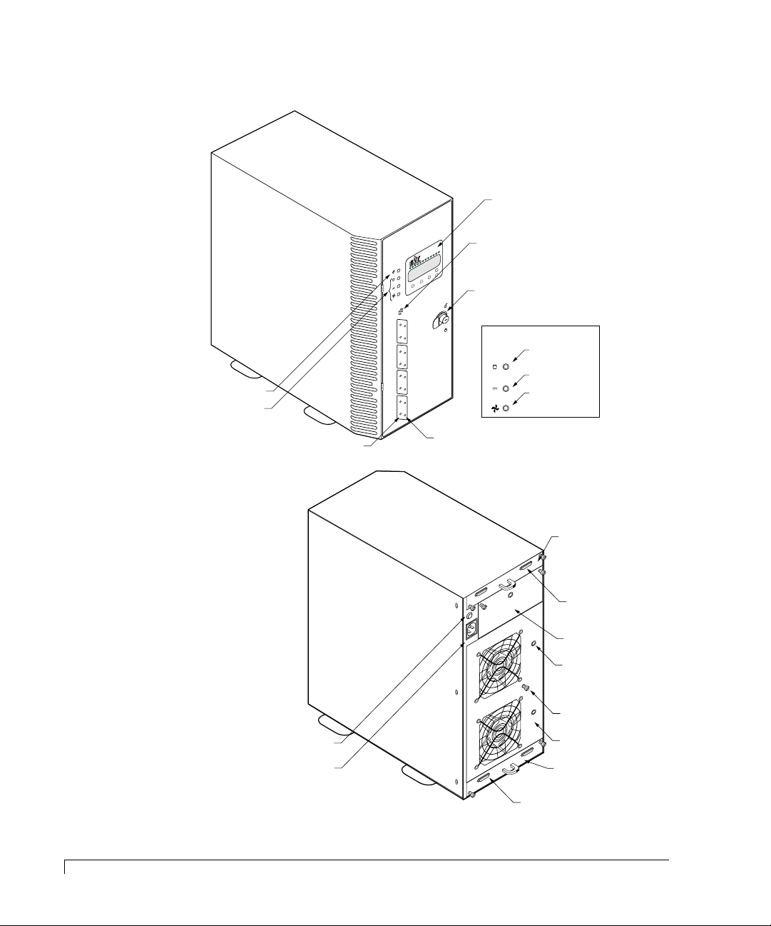
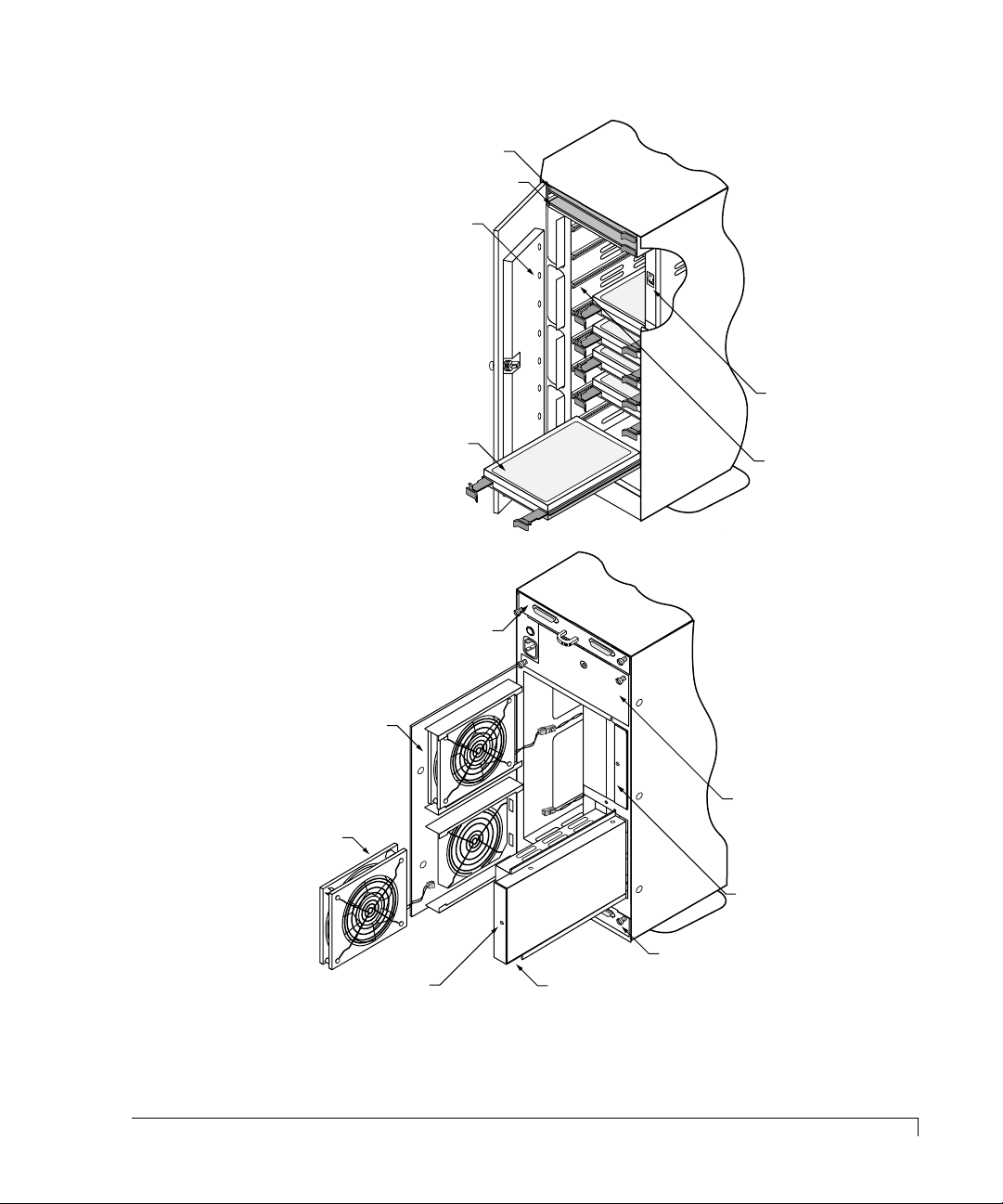
On the next two pages are illustrations that depicts the location of featured
components of the CR8e. Familiarize yourself with the subsystem’s components
and their descriptions prior to beginning the installation and using the CR8e.
Following the Components section, a Control and Monitoring section describes
the subsystem’s LEDs provides an explanation of the manner in which the CR8e
presents normal and abnormal conditions. The Operator Control Panel (OCP)
section describes in the general the features of the LCD panel and an illustration
pictorially describes items found on the display. In chapter 3 a more detailed
functional description of each OCP menu option is provided.
1
Page 14
Getting Started
Channel Mode LED
Power Supply LED
Fan Status LED
Status Indicator LEDs
Note: LEDs normally visible
only when illuminated,
shown here for identification.
Activity LEDs
Operator Control
Panel (OCP)
Speaker
Door Lock
Power-On LED
Status Indicator LEDs
Status LEDs
Rear Door Fastener
Rear Door Panel
AC Power Cord
Connector Module
I/O Interface Card
I/O Interface Card
VHD SCSI Connectors
VHD SCSI Connectors
Power Supply #3
with PSU Cover Plate
PSU “DC Good” LED
Fuse
CR8e Subsystem at a Glance
2
CR8e Subsystem at a Glance
Page 15
Bay for optional
Ultra S2S RAID Controller
SAF-TE Card
Fault LEDs
Getting Started
Power On/Off
Switch
Cooling Fan #2
Cooling Fan #1
Hard Disk Drive
I/O Interface Card
*
*
“DC Good” LED
Power Supply #1
Drive Rails
Note: Cover shown cut-away
to illustrate recessed power switch.
Power Supply #3
with PSU Cover Plate
Power Supply #2
I/O Interface Card
*
*
*
* Power supplies and cooling fans must be replaced by qualified service personnel only.
CR8e Subsystem at a Glance
3
Page 16

Getting Started
Components
This section provides a descriptive overview of each of the major components
that comprise the CR8e subsystem.
Hot Swap Disk Drives
The CR8e uses either 4.2 gigabyte , 9.1 gigab yte , or 18.2 gigab yte high performance,
3.5-inch form factor hot swap disk drives. The drives are designed to operate on
the Small Computer System Interface (SCSI) and are Ultra SCSI as well as SCSI-2
command compatible.
Each drive has an 80-pin Wide Single Connector Attachment (SCA-II) interface,
designed to allow the drive to be inserted directly into the backplane thus making
it possible to “hot swap” the drive without shutting down the subsystem.
The drive mounting design uses a rail system with built-in connectors which
allows for easy installation with minimal force. Latching clips ensure that the
drive is secured once it is installed.
4
Components
Hot Swap Cooling Fans
CAUTION:
The cooling system consists of two high-performance fans fitted to the rear panel.
These fans draw air from a high pressure plenum, across the drives and
electronics of the system and exhaust out through the rear door panel.
The fan speed is thermally controlled to provide r educed operating noise le vels. In
the event of a fan failure or the cabinet temperature approaches the threshold
limit, the remaining fan will switch to maximum operating speed.
Cabinet temperature is measured within the drive bay area between drive slots 2
and 3, and slots 7 and 8. The fan’s speed and alarm are key ed to the higher of the
two temperatures. The SAF-TE processor monitors the performance of each of
the fans via tach pulses which track the speed (RPM) of each fan impeller.
The fans can be replaced during normal operation without having to po wer do wn
the CR8e. In the event of a fan failure, the Fan Status LED will illuminate amber
and an alarm will sound.
Cooling fans must be replaced by qualified service personnel only.
Page 17

Getting Started
If an error occurs, access the Operator Control Panel to determine the cause and
locate the failed component. For more information, see
page 40. The fans are identified on the rear door panel using a placard for “FAN 1”
and “FAN 2.” For more information on changing a cooling fan, see
Cooling Fans
on page 60.
Operator Control Panel
Replacing the
on
Hot Swap Power Supplies
CAUTION:
Up to three 150 watt hot swap power supplies are incorporated as part of a
fault-tolerant design (N+1 power system). Each power supply unit (PSU) has
current share circuitry which balances the load between the installed power
supplies. In the event of a power supply failure, the load is transferred to the
remaining power supplies without interruption to the CR8e’s normal operation.
If a failure occurs, the Power Supply Status LED will illuminate amber and an
alarm will sound. The user can identify the failed component by accessing the OCP
and viewing the “Hardware Status.” The PSU “DC Good” LED will not be
illuminated on the failed power supply. For more information, see
Power Supply
Power supplies must be replaced by qualified service personnel only.
Replacing a
on page 58.
Power Switch
The power switch is located inside the locking fr ont door and controls AC po w er to
all of the power supplies. This positioning of the switch deters unauthorized users
from powering down the CR8e provided the door is locked. The switch is recessed
to prevent inadvertent activation during service activities.
The switch is labeled with a “I” for the ON condition and “O” for the OFF condition
and is illuminated when the power is on for easy identification. Depending on the
orientation of the subsystem (i.e., in the rack configuration) the “I” label will appear
as a “—” and should be interpreted as the ON condition.
Door Lock
The front door has an integral lock that also serves as a door handle. In addition,
the door lock provides security to deter unauthorized access to the disk drives and
SAF-TE card. Two keys are provided with the system.
To unlock the door, insert the key and turn it in a counterclockwise dir ection. To
lock the door, turn the key in a clockwise direction.
Hot Swap Power Supplies
5
Page 18
Getting Started
Channel 0
Channel 1
JP3 and JP4
Fault Bus Protocol
Jumpers (Add to
disable termination)
JP1 and JP2
Channel 0 and 1
Term Power Jumpers
I/O Interface Card
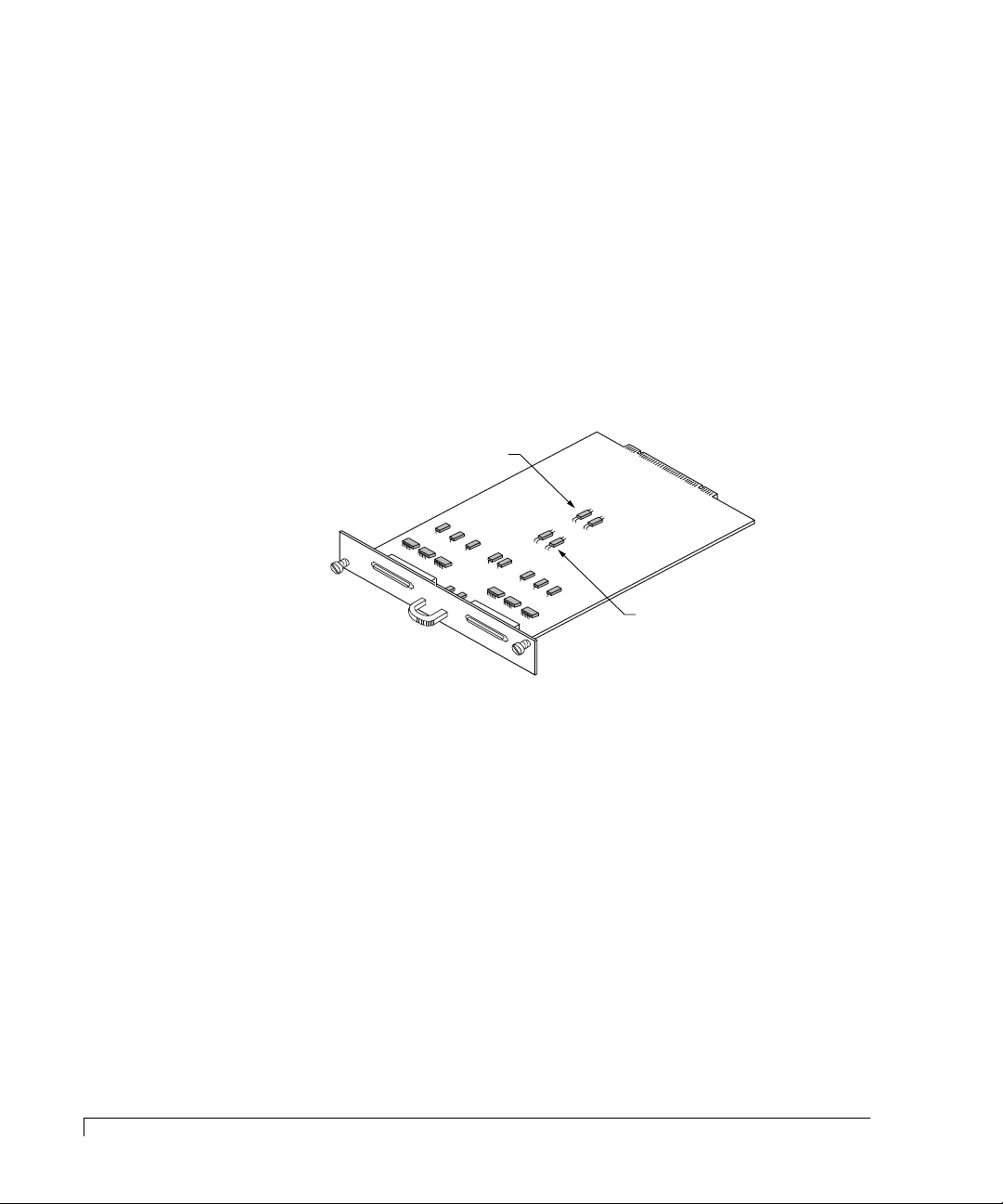
The I/O Interface card provides the connection from the subsystem’s bus to the
host adapter. Located on the I/O Interface card are two 68-pin very high density
(VHD) SCSI connectors. The connectors are labeled Channel 0 and Channel 1.
The I/O Interface card incorporates built-in automatic SCSI termination. When a
data cable is plugged in, the system automatically senses the connection and
provides the required SCSI termination.
Two sets of jumpers are provided on the card. One set of jumpers (JP1 and JP2)
routes Term Power in the event that the host controller does not provide it. The
default setting is the unjumpered condition (jumper offset on one pin only).
6
I/O Interface Card
The next set of jumpers, JP3 and JP4, addresses termination protocol for a specific
set of controllers that use the DEC Fault Bus. If you are using a DEC system
where the controller uses this protocol, y ou will need to jumper locations (jumper
on both pins) JP3 and JP4 for each channel that has an external SCSI cable
connected. This will disable termination at that point.
If you are using a standard host adapter that provides Term Power, no change is
required and SCSI bus termination will occur automatically.
Power Cord Connector and Fuse
The power cord connector supplies the AC power to the CR8e through a power
cord connected to a conventional three-hole grounded outlet or power strip. A
250V 10 amp fuse is provided to protect the system from any electrical fault.
Page 19
Configuration Modules
Getting Started
CAUTION:
Configuration modules must be installed or replaced by qualified
service personnel only.
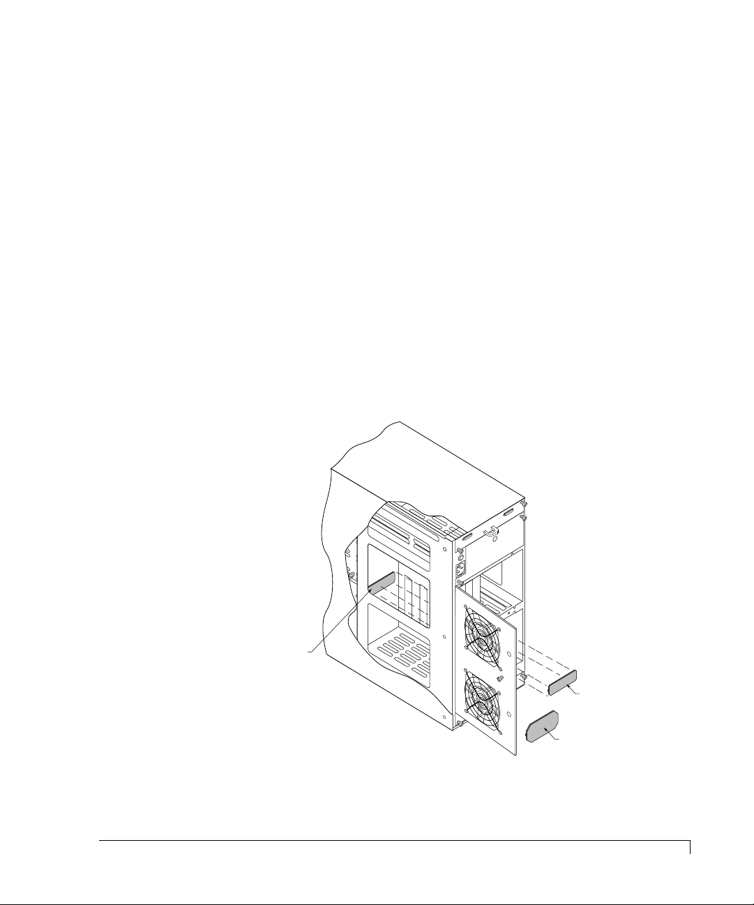
The CR8e’s SCSI bus design provides either of two bus configurations which is
determined by the configuration module installed. The Dual-Bus module pro vides
a split bus configuration where the enclosure’s top four drive slots and the lower
four drive slots are on two independent SCSI buses. The Single-Bus module
connects both SCSI buses together tying all drive slots to one SCSI bus.
The Single-Bus module is larger in physical size than the Dual-Bus module and is
easily identified by its description silkscreened on the module card. It is installed
on the backplane printed circuit board, at location JP1, and is accessed from the
rear door panel.
The connector is keyed and the module will only install in one direction. For
illustration purposes, the tower system is used to depict the location of the
modules.
Backplane PCB
(JP1)
NOTE: The cover is cut
away to demonstrate
the location of the installed
configuration module.
Dual-Bus Module
Single-Bus Module
Configuration Modules
7
Page 20
Getting Started
MENU ENTER ESCAPE
HARDWARE MENU
OPTIONS MENU
TURN OFF ALARM
Moves Menu
Selector Up
Appears When
More Options are
Available Above
Appears When
More Options are
Available Below
Moves Menu
Selector Down
Menu
Selector
firmware by lyle
Animated
Icon
Selects Menus Option or
Returns to Main Menu
Selects the Option
Indicated by Selector
Backs Up One Level
or Cancels Action
nStor
Controlling and Monitoring
An integral part of the CR8e is its control and monitor capabilities. The subsystem
enclosure contains a series of redundant alert notifications in the form of LEDs,
alarms, and an LCD Operator Control Panel. Each of these components are discuss
in the following topics.
Operator Control Panel
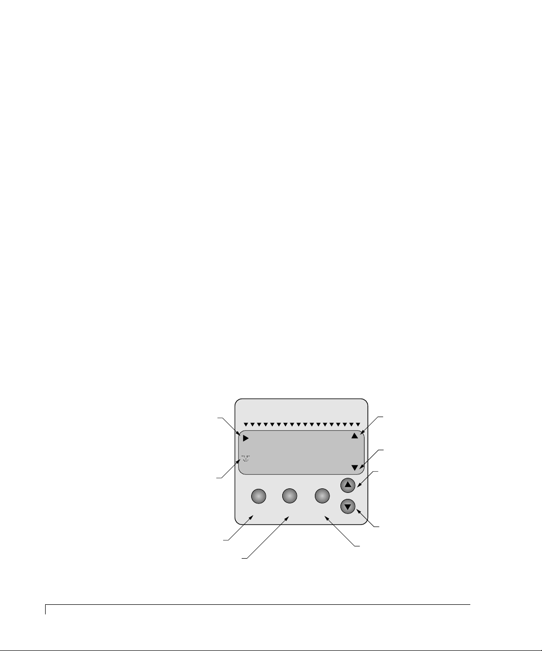
The Operator Control Panel (OCP) provides control and monitoring capabilities
through an LCD panel located on the front door of the CR8e. The disk drives,
power supplies, fans, and processor can be monitor ed for their status by using the
menu drive OCP interface. Also the user can maintain control of the subsystem
components by providing the capability to change to the disk drive SCSI IDs and
SAF-TE processor ID, and making changes to the temperature threshold for the
thermal monitoring system.
Other menu functions provide for viewing subsystem component status, silencing
the audible alarm, establishing a password to protect the subsystem OCP access,
establishing intra-cabinet communications (master/slave), and reading firmware
information.
8
Controlling and Monitoring
The OCP uses a four line by twenty character LCD display. There are five
function keys that define the menu driven interface.
Page 21

Getting Started
An animated icon will appear on the display after 30 seconds of no OCP input
activity and provides an “at-a-glance” look at system status. When a “happy”
animated face appears, all systems are indicating a nominal state. When the
animated face changes to a “sad” face, the system indicates that a problem has
been detected and requires attention.
The “power system” status will display the total power available per drive slot in
redundant and non-redundant mode. A maximum supported value of 30 watts
per drive bay is av ailable in either mode. Also the user can view individual power
supply status and configurations.
The OCP displays information on each cooling fan’s speed. Each fan’s speed
(RPM) is controlled via the internal cabinet thermal monitoring system,
referenced from a user-established temper atur e thr eshold. Cabinet temper ature is
measured within the drive bay ar ea between driv e slots 2 and 3, and between slots
7 and 8. By sensing cabinet temperature in these locations, the system provides
the most sensitive measurement for maximum protection. The temperature is
displayed in both Celsius and Fahrenheit. The SAF-TE processor monitors the
performance of each fan via tach pulses which track the speed (RPM) of each fan
impeller.
LEDs
Power-On LED
The Power-On LED signifies that the CR8e system has power applied.
Status Indicator LEDs
There are three Status Indicator LEDs to assist the user in determining the current
state of the CR8e subsystem. The following subsections describe each LED.
Channel Mode
The Channel Mode LED indicates the status of the subsystem array by changes in
its color and state. Steady green indicates normal array activities.
When the LED changes to amber (flashing or steady) it indicates abnormal
activities. For more information see LED Descriptions on page 39.
LEDs
9
Page 22

Getting Started
Power Supply Status
The Po wer Supply Status LED indicates the condition of the power supplies. The
LED will illuminate steady green when all the power supplies are functioning
normally and will change to amber if one of the power supplies should fail. The
LED will also switch to amber if the power system is in a non-redundant state. A
failed component can be identified via the Operator Control Panel and the lack of
an illuminated “DC Good” LED located on each power supply unit.
Fan Status
The Fan Status LED indicates the condition of the cooling fans by changes in its
color. The LED will illuminate green when all of the fans are functioning normally
and will change to amber if any of the fans fail.
When a failed component is present, use the Operator Control Panel to identify
the failed fan. The fans are identified on the rear door panel via placarded
markings. For more information see Hardware Menu on page 42.
Status LEDs
10
There are eight Status LEDs located in windows on the front panel (for the
rack-mount system they are the lo wer set of LEDs and for the to w er-based system
they will be the set on the left hand side).
These LEDs, in conjunction with an approved RAID controller, will indicate the
status of a specific disk drive by their state (flashing or steady) and/or color
(amber or green).
For more information on interpreting these indications, see LED Descriptions on
page 39.
Activity LEDs
There are eight Activity LEDs located in windows on the front panel (for the
rack-mount system they are the upper set of LEDs and for the to wer-based system
they will be the set on the right hand side). These LEDs will flash indicating a
specific drive is being accessed, either as reads or writes.
LEDs
Page 23

Getting Started
Alarm Speaker
An audible alarm will sound when any component’s condition changes to an
abnormal state. The Status Indicator LEDs conditions (color and/or state) will
provide a general area of failure, and the failed component can then be identified
using the Operator Control Panel.
To silence the alarm, access the control panel and select “Turn Off Alarm.” For
more information see Main Menu on page 42.
Fault LEDs
When a disk drive is installed in a drive slot, it has a corresponding Drive Fault
LED that will illuminate to aide in identifying a failed or problem disk drive.
These LEDs are located on the inside front door panel and are aligned with their
respective drive slot. If the LED is illuminated (amber), the condition indicates a
failed or problem drive found in that drive slot.
SAF-TE Card
The SAF-TE card contains the control and monitoring electronics for the
subsystem cabinet. It provides the central data link betw een the enclosure and the
host system.
Located in the tower-based systems’ top bay (the r ack-mount systems’ far left bay)
are two card slots. The SAF-TE card is installed in the lower (furthest right) of
the two slots. The upper slot (furthest left slot) is not used.
SAF-TE
The CR8e is designed to be compliant with version 1.0 of the SAF-TE (SCSI
Accessed Fault-Tolerant Enclosure) specification. Under this specification, the
enclosure is implemented as an assignable SCSI target ID. This allows
standardized alert detection and status reporting using the SCSI bus as the
underlying transport mechanism.
Alarm Speaker
11
Page 24

Getting Started
Disk drives, power supplies, cooling fans and temperature are continually
monitored and these conditions are then reported over the SCSI bus to the host
system.
When used in conjunction with the A dminiStor Stor age Management software , the
CR8e can alert the user or LAN administrator of conditions requiring their
attention. These alert notifications can be made via network br oadcast or electr onic
pages, in addition to the LEDs and Operator Control Panel alerts found on the
CR8e subsystem. This allows the administrator to receive remote notification of
conditions that require corrective action to prevent data loss.
12
SAF-TE Card
Page 25

2
Installation
Setup
The installation of your nStor CR8e disk array subsystem is essentially a
three-step process: the subsystem is setup and its components installed, the
cabling is completed based on the supported configurations, and the array is then
configured.
This chapter is divided into two sections: Setup and Cabling Configuration. The
Setup section provides the instructions for assembling the rack-mount subsystem,
and installing the hardware components (contr ollers, disk driv es, pow er supplies,
etc.,) for both rack-mount and deskside tower-based subsystems.
The Cabling Configuration section contains samples of cabling schemes and
configurations. If your desired configur ation is not shown in the samples, refer to
the example most similar and follow the cabling topology scheme expanding the
configuration example to fit your needs while conforming to the specific SCSI
specification.
The CR8e is designed with an open architecture that allows for many possible
combinations of cabling schemes. Because of these possible combinations, we will
provide a sampling of configurations in this chapter.
Additional configurations are available through the use of nStor’s Ultra Extender
or Differential Converter Feature cards. Refer to the nStor Feature Card User’s
Guide for information specific to each card and configuration. When configuring
the array, refer to the user’s guide provided with your RAID controller.
13
Page 26

Installation
System Requirements
The nStor CR8e disk subsystem is based on an open architecture design and can
be connected to any host-based SCSI system. R efer to your adapter/contr oller and
host system user’s manuals for information about the system requirements for
the host system where the controller will be installed.
Guidelines
Before installation, you will need to consider the following:
■ When referencing a component on the rear panel it is assumed the user is
facing the rear panel and when referencing the fr ont panel components the
assumption is that the user is facing the front panel.
■ Interior temperature of the rack cabinet should be maintained at ambient
temperatures but must not exceed 117°F (47°C) during normal operation.
■ Remove each piece from the shipping carton, leaving the disk drives in
their anti-static protective packaging until you are ready to install them.
■ Save the packing materials in case you need to ship the CR8e.
■ Secure all cable connectors using the thumb screws (finger tight only).
■ When connecting the data cable VHD connectors, be sure to exercise
caution that the connector is inserted carefully and correctly. Otherwise it
is very likely to bend the pins inside the connector.
14
System Requirements
Page 27
Installation
A
8-32 Pan Head
Screws
8-32 Caged
Nuts
Washers
Front Rack Vertical
Rear Rack Vertical
Rack-Mount Subsystem Assembly
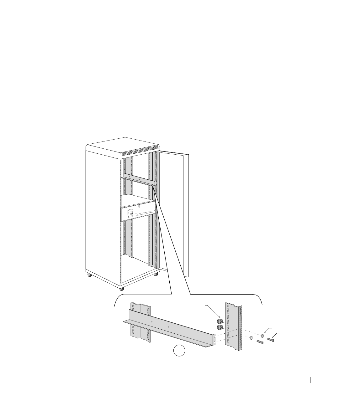
You can install the CR8e into any standard IAE 19" rack cabinet.
CAUTION: Ensure that the location of the CR8e does not create an unstable
condition when installed in the rack cabinet enclosure.
NOTE: Mount the subsystem into the rack enclosure before installing the disk
drives. This will reduce the weight r equired to support during installation.
1 Select an appropriate location in your rack cabinet for the CR8e. If you are
installing multiple systems, review the cabling configuration section later in
this chapter for your cable scheme to determine the optimum locations.
Rack-Mount Subsystem Assembly
15
Page 28
Installation
Rail is installed to
the front and rear
rack cabinet verticals.
8-32 Pan
Head Screws
2 To aide in support bracket installation, remove the rack cabinet side panels.
3 Locate the two support brackets. Mount the two brackets to the rack cabinet
verticals using the four screws, four washers, and four caged nuts provided
for each bracket. Refer to detail “A” in the illustration on the previous page.
NOTE: The caged nuts are secured into the r ack cabinet v ertical slots by inserting
one side of the nut into the slot and squeezing while pressing the opposite
side in until it snaps into place.
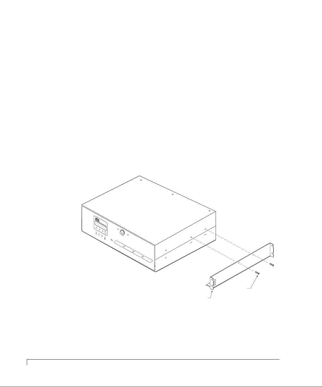
4 Remove the two (2) upper enclosure case screws as depicted below on the
right side of the subsystem cabinet.
NOTE: The enclosure is attached to the support bracket only on the right side.
5 Slide the subsystem cabinet into the cabinet with the subsystem riding on top
of the support brackets.
6 Align the two upper case screw holes with those provided in the support
bracket on the right side.
16
Rack-Mount Subsystem Assembly
7 Secure the subsystem cabinet to the right hand rail using the two (2) screws
previously removed.
8 Continue with the component installation on the next page.
Page 29

Installation
Component Installation
CAUTION: Disk drives and printed circuit board components are sensitive to
electrostatic discharge. To prevent operating failure or damage,
observe the following: Establish a ground for yourself by using the
wrist grounding strap, or by touching the metal chassis prior to
handling or installing the drives or printed circuit board components.
1 Down your server or power off your computer system in preparation for
installing the host adapter (if applicable).
2 Install the adapter into your host computer. For specific instructions, refer to
your host system’s manual and the host adapter’s user guide.
CAUTION: Exercise care when handling any hard disk drive. Do not drop, jar , or
bump the disk drives.
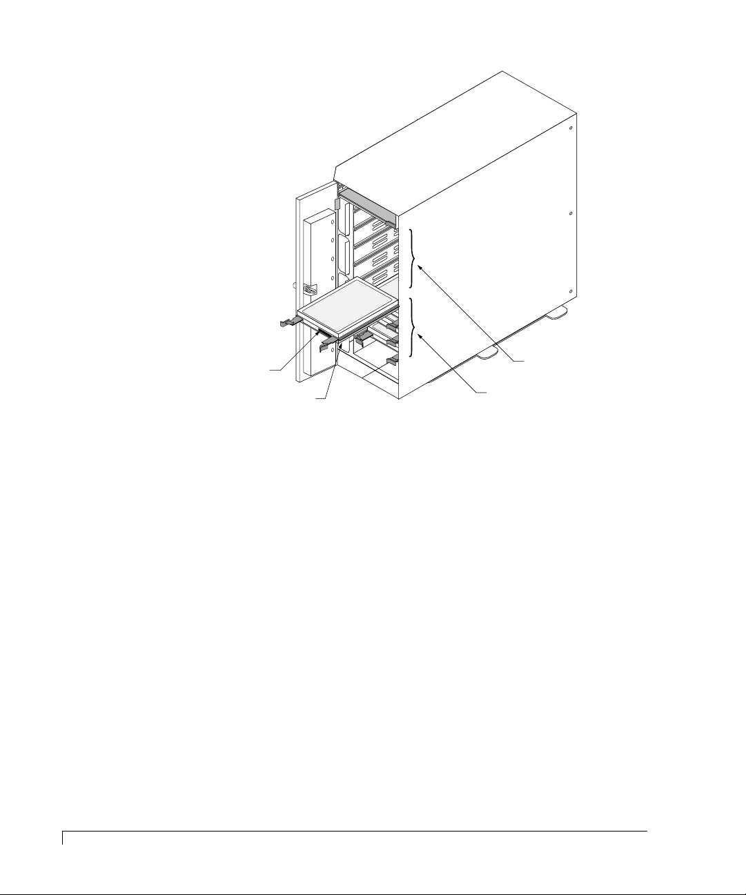
3 Install the disk drives. Remove one of the disk drives from its anti-static
protective packaging.
4 Holding the drive by its edges, locate the Drive Latching Clips and pull out on
the latches to unlock them.
The Drive Latching Clips are placed in the locked position for shipping
purposes.
5 Insert the disk drive into the drive bay by aligning its rails into the drive bay
slots, component side toward the right on rack-mount systems or component
side down on tower-based systems.
Dual-Bus module - The drive slots are split into two buses: one bus
connects the left or upper four drive slots and the other
bus connects the right or lower four drive slots.
Depending on to which bus the drives will be configured,
begin populating the drives starting with the far right
slot or lowest slot for that bus.
Single-Bus module -
The Single-Bus module connects all eight drive slots to
one bus. B
lowest drive slot and work to your left or up.
egin populating the drive with the far right or
Component Installation
17
Page 30
Installation
Populate drive bays from
the lower (right) slot first.
Drive Label
Component side
Upper (left) bay,
four drive slots
Lower (right) bay,
four drive slots
6 Fully seat the drive by applying pressure with your thumb to the front of the
drive.
7 Press the Drive Latching Clips until they “snap” into place. The drive is now
locked into position.
8 Install the remaining drives repeating steps 3 through 7, until all the drives
have been installed, as desired.
NOTE: Verify that the power switch on the CR8e is in the OFF position (O).
9 Connect one end of the power cord to the power connector on the rear panel
and the other end to a three-hole grounded outlet or power strip. A UPS is
recommended.
10 Refer to the “Cabling Configuration” on page 20 to complete the data cable
connections if you are using the AM RAID Controller card. If you are using
the Ultra S2S RAID Controller, refer to the nStor Ultra S2S RAID Controller
and PC Utilities User’s Guide for information about cabling configurations.
18
Component Installation
Page 31
Installation
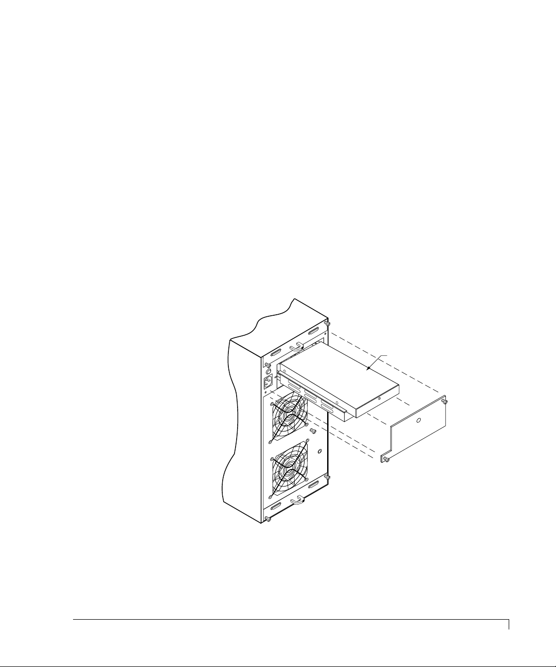
Installing the Third Power Supply
If you will be installing five (5) or more disk drives you will be required to install
the third power supply.
CAUTION: Power supply installation is to be performed by qualified service
personnel only. There is no need to power off the CR8e or the
computer system. The power supplies are hot swappable.
1 Loosen the two screws on the Power Supply #3 cover plate using a flat-blade
screwdriver and remove the cover plate.
2 Remove the power supply from its shipping package.
3 Install the third power supply by sliding the PSU into the cabinet until it
reaches its locked position. Orient the supply as indicated in the illustration.
NOTE: Use care when inserting the power supply into its fully seated position.
Do not use a strong force to seat the PSU into its mating connector.
Power Supply #3
4 Remove the blanking plug for the LED on the cover plate.
5 Re-install the cover plate. Secure the cover plate with the two screws using a
flat-blade screwdriver securing the power supply.
Component Installation
19
Page 32

Installation
Cabling Configuration
The Ultra Wide SCSI mode provides enhanced performances with data transfers
up to 40 MBs per second (20 MHz), while the Fast Wide SCSI mode will provide
transfers up to 20 MBs per second (10 MHz).
The cabling configuration section is divided into two subsections, Ultra Wide
SCSI and Fast Wide SCSI. These two sections provide the recommended cable
configurations when operating the CR8e in a specific mode.
The CR8e supports the American National Standard Ultra SCSI (F ast-20) par allel
interface standards, referred to as Ultra Wide SCSI. This standard is backward
compatible with Fast SCSI (SCSI-2 with the Wide option), also r eferred to as Fast
Wide SCSI. This standard defines the mechanical, electrical, and timing
requirements. In compliance with these interface standards, certain limitations
apply when considering the configuration, lengths of cabling, and termination.
The configuration samples and cables provided with the subsystem meet the
requirements of the specifications. Modifications to any of these variables can
have less than desirable results when operating any SCSI device.
20
Cabling Configuration
General
Cables
Cable length is a critical consideration when configuring the subsystems. There
are different limitations for Ultra Wide SCSI and Fast Wide SCSI.
When calculating the total length of your cabling, the internal subsystem length
of cables and printed circuit board traces (known as the internal cable length)
must be subtracted from your total cable length. The CR8e internal cable length is
36 inches.
For Ultr a Wide SCSI, the total SCSI cable length is 3 meters (118 inches) with
four drives and 1.5 meters (59 inches) with eight drives. After subtracting the
internal length of 36 inches the remaining cable length is 82 inches or
approximately 6.83 feet (2.08 meters) for four drives and 23 inches or
approximately 1.9 feet (.58 meters) for eight drives.
For Fast Wide SCSI, the total SCSI cable length is 6 meters (236 inches) with
four drives and 3 meters (118 inches) with eight drives. After subtracting the
internal length of 36 inches the remaining cable length is 200 inches or
approximately 16.66 feet (5.08 meters) for four drives or approximately 6.83
feet (2.08 meters) for eight drives.
Page 33
Installation
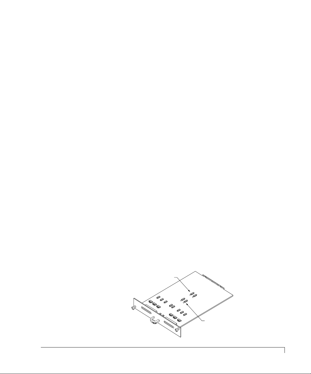
Channel 0
Channel 1
JP3 and JP4
Fault Bus Protocol
Jumpers (Add to
disable termination)
JP1 and JP2
Channel 0 and 1
Term Power Jumpers
Because of the enhancements in the CR8e, its possible to e xtend bey ond the limits
set forth in the specification. However, a symptom from exceeding this cable limit
is a SCSI bus lockup or “freeze.” If you experience a similar problem and are
aware of a cabling limit issue, reducing the length of cabling and returning the
total length to within the specified limit should resolve any problems.
If you have a cabling issue and r equire mor e information, contact nStor Technical
Support for further assistance. Data loss is possible under conditions of SCSI bus
lockup.
NOTE: Shielded data cables, such as those provided with the subsystem, must be
used to prevent r adio fr equenc y interfer ence. It is recommended that you
use the cables provided by nStor. These cables have been tested and meet
stringent guidelines set forth by SCSI-3 ANSI specifications.
Termination
Termination is required at both ends of the SCSI bus. There are two sets of
jumpers on the I/O Interface card. One set of jumpers (JP1 and JP2) routes “T erm
Po wer” in the e vent that the host contr oller is not pro viding it. The default setting
is the unjumpered condition (jumper offset on one pin only). The second set of
jumpers addresses a specific set of controllers that use the DEC Fault Bus
protocol. If your controller uses this pr otocol, you will need to jumper (jumper on
both pins) at location JP3 and JP4 on the backplane for the indicated channel that
will be used. A jumper at either of these locations will disable termination at that
point on the SCSI bus.
If you are using a controller that pr ovides Term Power, no change is required and
SCSI bus termination will occur automatically.
Most RAID controllers provide termination for one end of the SCSI bus, while
the I/O Interface card provide final termination at the other end of the bus.
General
21
Page 34

Installation
Ultra Wide SCSI Mode
Several possible configurations exist for the CR8e in Ultra Wide SCSI mode.
However this manual will discuss the two possible configurations using the I/O
Interface card in Ultra Wide SCSI mode: dual-bus module in a single enclosure and
single-bus module in a single enclosure. Refer to the nStor Feature Card User’s
Guide for additional configurations when using the Ultra Extender or Differential
Converter card.
When configuring a dual-bus enclosure subsystem with an AM RAID Controller,
one channel on the controller connects to Channel #0 on the I/O Interface card
and the other channel on the controller connects to Channel #1 on the I/O
Interface card – each channel addresses either the upper (right) or lower (left)
bank of drives. When configuring the single-bus enclosure with an AM RAID
Controller, one channel on the controller connects to the right or upper channel
(Channel #1) connector on the I/O Interface card and addresses both banks of
drives.
From the front, the drives slots ar e divided into tw o banks. The left or upper four
front drive slots, which are connected to “Channel 1” on the I/O Interface card,
and the right or lower four front drive slots are connected to “Channel 0” on the
I/O Interface card.
22
Ultra Wide SCSI Mode
Dual-Bus Enclosure
With this configuration you will have a total storage capacity of up to 145 GB
(using 18 GB disk drives) per subsystem enclosure.
The SCSI IDs of the drives are set by the S AF-TE card defaults to IDs 0, 1, 2, and
4, from the front beginning with the drive located on the right or lower slot of
each bank. The SCSI IDs can be manually changed from the OCP, if required.
Both banks of drives will normally use the same sequence of SCSI ID numbers
when the Dual-Bus module is installed.
NOTE: SCSI ID 3 is reserved for the SAF-TE card processor.
CAUTION: Ensure that the power switch is in the OFF (O) position for both the
host system and the CR8e subsystem before connecting any cables.
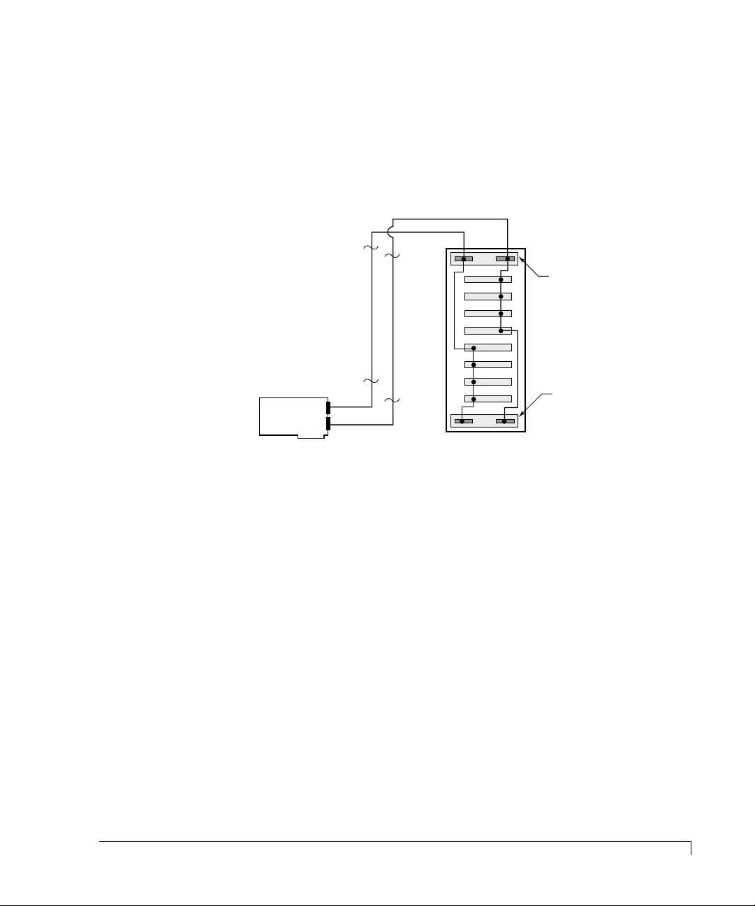
1 Connect one end of a one meter data cable to the Channel #1 connector on
the AM RAID Controller.
Page 35
Installation
Rear View CR8e
with Dual-Bus Module installed.
TOP
I/O Interface
Card
1 meter data cable
1 meter data cable
I/O Interface
Card
Ultra SCSI
RAID Controller
Ch 0
Ch 1
Ch 0
Ch 1
Ch 1
Ch 2
2 Connect the other end of the data cable to the Channel #0 SCSI connector on
the right side or upper I/O Interface card.
3 If required, connect one end of the second one meter data cable to the
Channel #2 connector on the AM RAID Controller.
4 Connect the other end of the second data cable to the Channel #1 SCSI
connector on the right side or upper I/O Interface card.
NOTE: SCSI termination is automatic and requires no user configuration. Refer
to “Termination” on page 21 for information on systems using DEC
Fault bus protocol.
5 Turn on the power to the CR8e. After the power-on self-test has completed,
Status and Channel Mode LEDs will be solid green.
6 Access the Options menu on the Operator Control Panel and choose the
SAFTE CHAIN ID selection. Choose the “None” selection, refer to “SAFTE
CHAIN ID” on page 50.
7 After setting the cabinet identifications you must power cycle the subsystem.
Observe normal power cycling precautions by waiting a minimum of five (5)
seconds before adding power again.
This will reset the SCSI IDs to a default setting that prevents a SCSI ID
conflict under normal conditions.
8 Power up your computer system and run the configuration program.
This completes the hardware installation.
Ultra Wide SCSI Mode
23
Page 36
Installation
Rear View CR8e
with Single-Bus Module installed.
TOP
I/O Interface
Card
1 meter data cable
I/O Interface
Card
Ultra SCSI
RAID Controller
Ch 0
Ch 1
Ch 0
Ch 1
Ch 1
Single-Bus Enclosure
With the Single-Bus module is installed, all of the disk drives in the CR8e
enclosure are on the same SCSI bus. With this configuration you will have a total
storage capacity of up to 145 GB (using 18 GB disk drives) per subsystem
enclosure and have access to the drives independently or as a single large array.
The SCSI IDs of the drives are set by SAF-TE card defaults to IDs 0 through 9,
and are assigned sequentially beginning with the lowest or far right drive.
NOTE: SCSI ID 3 is reserved for the SAF-TE card processor and ID 7 reserved
for the RAID controller.
CAUTION: Ensure that the power switch is in the OFF (O) position for both the
host system and the CR8e subsystem before connecting any cables.
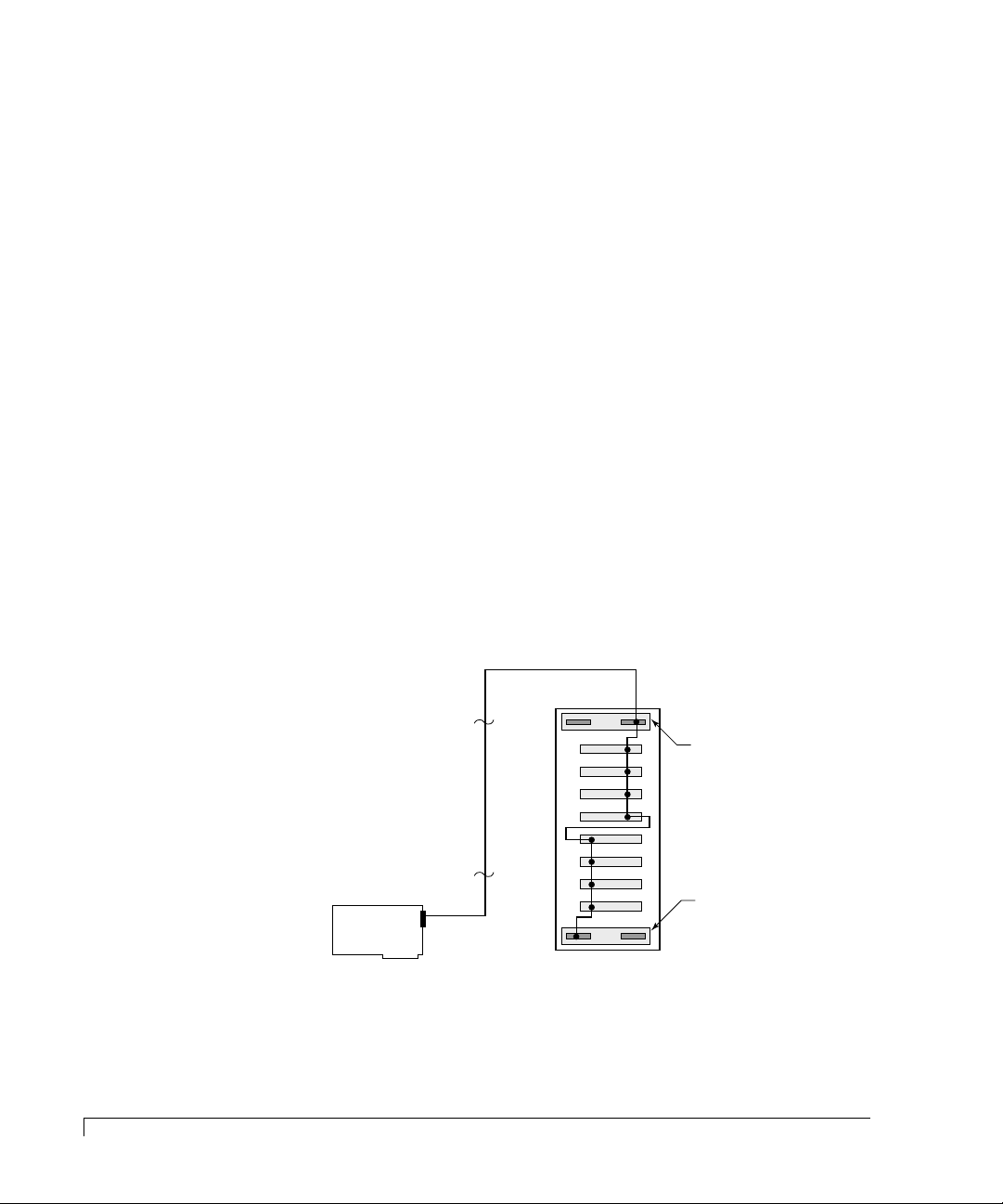
1 Connect one end of a one meter data cable to the Channel #1 connector on
the AM RAID Controller.
2 Connect the other end of the data cable to the Channel #1 SCSI connector on
the upper or right side I/O Interface card.
24
Ultra Wide SCSI Mode
NOTE: The Channel #1 connector located on the upper or right side I/O Interface
card is the active connector when the Single-Bus module is installed.
NOTE: SCSI termination is automatic and requires no user configuration. Refer
to “Termination” on page 21 for information on systems using DEC
Fault bus protocol.
Page 37

Installation
3 Turn on the power to the CR8e. After the power-on self-test has completed,
Status and Channel Mode LEDs will be solid green.
4 Access the Options menu on the Operator Control Panel and choose the
SAFTE CHAIN ID selection. Choose the “None” selection, refer to “SAFTE
CHAIN ID” on page 50.
5 After setting the cabinet identifications you must power cycle the subsystem.
Observe normal power cycling precautions by waiting a minimum of five (5)
seconds before adding power again.
This will reset the SCSI IDs to a default setting that prevents a SCSI ID
conflict under normal conditions.
6 Power up your computer system and run the configuration program.
This completes the hardware installation.
NOTE: For additional configuration options using Ultra Wide SCSI, refer to the
nStor Feature Card User’s Guide.
Ultra Wide SCSI Mode
25
Page 38

Installation
Fast Wide SCSI Mode
Several possible configurations exist for the CR8e in the Fast Wide SCSI mode:
dual-bus with one or two enclosures, single-bus with one or two enclosures, and
one dual-bus enclosure with two single-bus enclosures connected.
When configuring a dual-bus enclosure subsystem with an AM RAID Controller,
one channel on the controller connects to Channel #0 on the I/O Interface card
and the other channel on the controller connects to Channel #1 on the I/O
Interface card – each channel addresses either the upper (right) or lower (left)
bank of drives. When configuring the single-bus enclosure with an AM RAID
Controller, one channel on the controller connects to the right or upper channel
(Channel #1) connector on the I/O Interface card and addresses both banks of
drives.
From the front, the drives slots ar e divided into tw o banks. The left or upper four
front drive slots, which are connected to “Channel 1” on the I/O Interface card,
and the right or lower four front drive slots are connected to “Channel 0” on the
I/O Interface card.
26
Fast Wide SCSI Mode
Single Dual-Bus Enclosure
With the Single-Bus module is installed, all of the disk drives in the CR8e
enclosure are on the same SCSI bus. With this configuration you will have a total
storage capacity of up to 145 GB (using 18 GB disk drives) per subsystem
enclosure and have access to the drives independently or as a single large array.
The SCSI IDs of the drives are set by the S AF-TE card defaults to IDs 0, 1, 2, and
4, from the front beginning with the drive located on the right or lower slot of
each bank. The SCSI IDs can be manually changed from the OCP, if required.
Both banks of drives will normally use the same sequence of SCSI ID numbers
when the Dual-Bus module is installed.
NOTE: SCSI ID 3 is reserved for the SAF-TE card processor.
CAUTION: Ensure that the power switch is in the OFF (O) position for both the
host system and the CR8e subsystem before connecting any cables.
1 Connect one end of a one meter data cable to the Channel #1 connector on
the AM RAID Controller.
Page 39
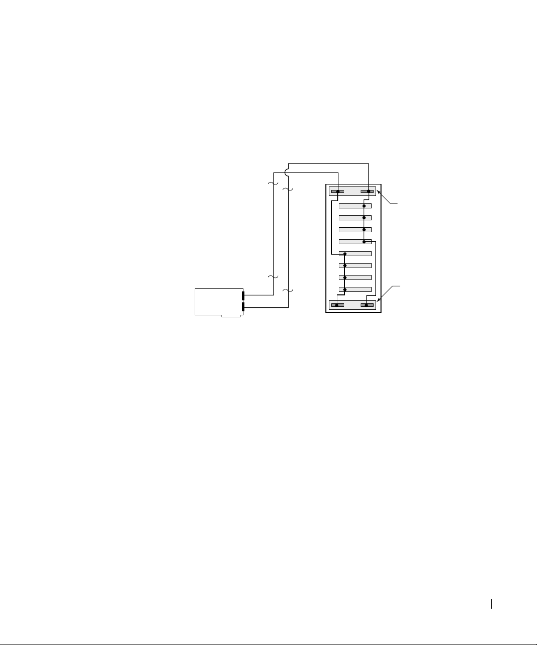
Installation
Rear View CR8e
with Dual-Bus Module installed.
TOP
I/O Interface
Card
1 meter data cable
1 meter data cable
I/O Interface
Card
Ultra SCSI
RAID Controller
Ch 0
Ch 1
Ch 0
Ch 1
Ch 1
Ch 2
2 Connect the other end of the first data cable to the Channel #0 SCSI
connector on the right side or upper I/O Interface card.
3 If required, connect one end of the second one meter data cable to the
Channel #2 connector on the AM RAID Controller.
4 Connect the other end of the second data cable to the Channel #1 SCSI
connector on the right side or upper I/O Interface card.
NOTE: SCSI termination is automatic and requires no user configuration. Refer
to “Termination” on page 21 for information on systems using DEC
Fault bus protocol.
5 Turn on the power to the CR8e. After the power-on self-test has completed,
Status and Channel Mode LEDs will be solid green.
6 Access the Options menu on the Operator Control Panel and choose the
SAFTE CHAIN ID selection. Choose the “None” selection, refer to “SAFTE
CHAIN ID” on page 50.
7 After setting the cabinet identifications you must power cycle the subsystem.
Observe normal power cycling precautions by waiting a minimum of five (5)
seconds before adding power again.
This will reset the SCSI IDs to a default setting that prevents a SCSI ID
conflict under normal conditions.
8 Power up your computer system and run the configuration program.
This completes the hardware installation.
Fast Wide SCSI Mode
27
Page 40
Installation
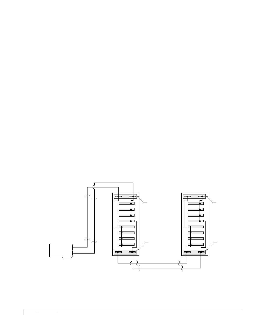
Two Dual-Bus Enclosures
With this configuration you will have a total storage capacity of up to 290 GB
(using 18 GB disk drives) which provides 145 GB per channel per subsystem
enclosure.
This configuration is similar to the “Single Dual-Bus Enclosure” except that the
capacity is expanded with a second cabinet providing a total of eight drives per
SCSI channel.
CAUTION: Ensure that the power switch is in the OFF (O) position for both the
host system and the CR8e subsystem before connecting any cables.
1 Connect one end of a one meter data cable to the Channel #1 connector on
the AM RAID Controller.
2 Connect the other end of the first data cable to the Channel #0 SCSI connector on
the right side or upper I/O Interface card.
3 Connect one end of the second one meter data cable to the Channel #2 connector
on the AM RAID Controller.
4 Connect the other end of the second data cable to the Channel #1 SCSI connector
on the right side or upper I/O Interface card.
Ultra SCSI
RAID Controller
Ch 1
Ch 2
Ch 0
1 meter data cable
1 meter data cable
TOP
Ch 1
Rear View CR8e
with Dual-Bus Module installed.
Ch 0
Ch 1
14-inch jumper cable
14-inch jumper cable
I/O Interface
Card
I/O Interface
Card
Ch 0
TOP
Ch 1
Rear View CR8e
with Dual-Bus Module installed.
Ch 0
Ch 1
I/O Interface
Card
I/O Interface
Card
5 Locate the jumper cables. Connect one end of a jumper cable to the Channel #0
SCSI connector on the left side or lower I/O Interface car d in the first cabinet.
28
Fast Wide SCSI Mode
Page 41

Installation
6 Connect the other end of the jumper cable to the Channel #0 SCSI connector
on the left side or lower I/O Interface card in the second cabinet.
7 Connect one end of a second jumper cable to the Channel #1 SCSI connector
on the left side or lower I/O Interface card in the first cabinet.
8 Connect the other end of the second jumper cable to the Channel 1 SCSI
connector on the left side or lower I/O Interface card in the second cabinet.
NOTE: SCSI termination is automatic and requires no user configuration. Refer
to “Termination” on page 21 for information on systems using DEC
Fault bus protocol.
9 Turn on the power to the CR8e. After the power-on self-test has completed,
Status and Channel Mode LEDs will be solid green.
10 Access the Options menu on the Operator Control Panel and choose the
SAFTE CHAIN ID selection. For each subsystem, identify which subsystem
will be the master cabinet and which will be the slave cabinet. (Generally, the
master cabinet will the subsystem connected to the controller.) Refer to
“SAFTE CHAIN ID” on page 50.
11 After setting the cabinet identifications you must power cycle the subsystem.
Observe normal power cycling precautions by waiting a minimum of five (5)
seconds before adding power again.
This will reset the SCSI IDs to a default setting that prevents a SCSI ID
conflict under normal conditions.
12 Power up your computer system and run your configuration program.
This completes the hardware installation.
Fast Wide SCSI Mode
29
Page 42
Installation
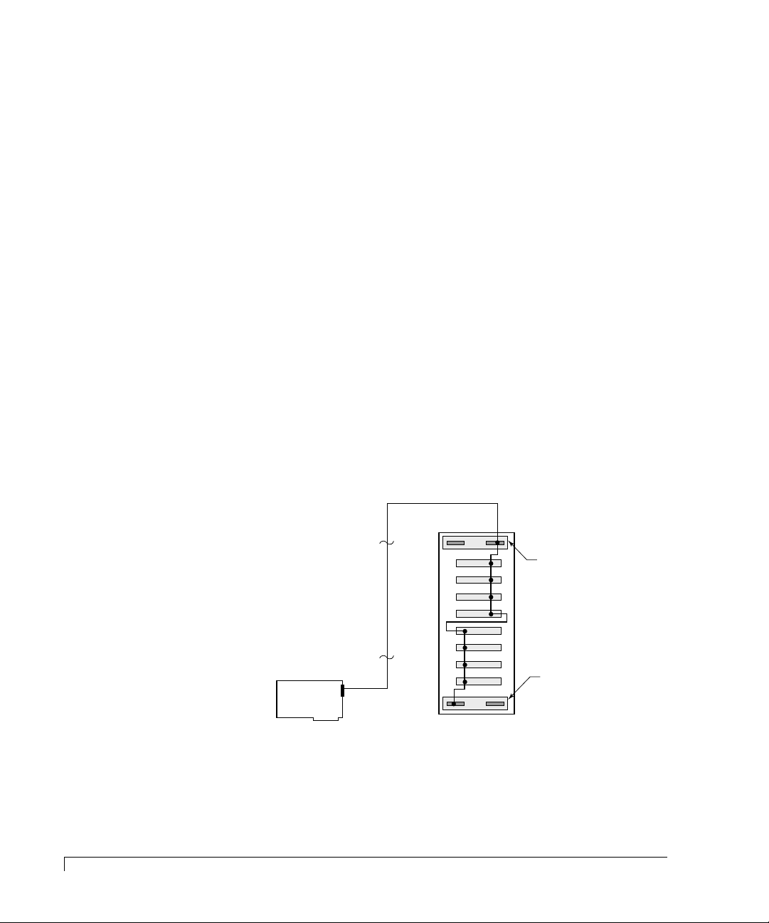
Single-Bus Enclosure
With the Single-Bus module is installed, all of the disk drives in the CR8e
enclosure are on the same SCSI bus. With this configur ation you will have a
total storage capacity of up to 145 GB (using 18 GB disk drives) per subsystem
enclosure and have access to the drives independently or as a single large array.
The SCSI IDs of the drives are set by SAF-TE card defaults to IDs 0 through
9, and are assigned sequentially beginning with the lowest or far right drive.
NOTE: SCSI ID 3 is reserved for the SAF-TE card processor and ID 7 reserved
for the RAID controller.
CAUTION: Ensure that the power switch is in the OFF (O) position for both the
host system and the CR8e subsystem before connecting any cables.
1 Connect one end of a one meter data cable to the Channel #1 connector on
the AM RAID Controller.
2 Connect the other end of the data cable to the Channel #1 SCSI connector on
the upper or right side I/O Interface card.
NOTE: The Channel #1 connector located on the upper or right side I/O Interface
card is the active connector when the Single-Bus module is installed.
30
Fast Wide SCSI Mode
TOP
Ch 1
Ch 1
I/O Interface
Card
I/O Interface
Card
Ultra SCSI
RAID Controller
Ch 1
Ch 0
1 meter data cable
Rear View CR8e
with Single-Bus Module installed.
Ch 0
NOTE: SCSI termination is automatic and requires no user configuration. Refer
to “Termination” on page 21 for information on systems using DEC
Fault bus protocol.
Page 43

Installation
3 Turn on the power to the CR8e. After the power-on self-test has completed,
Status and Channel Mode LEDs will be solid green.
4 Access the Options menu on the Operator Control Panel and choose the
SAFTE CHAIN ID selection. Choose the “None” selection, refer to “SAFTE
CHAIN ID” on page 50.
5 After setting the cabinet identifications you must power cycle the subsystem.
Observe normal power cycling precautions by waiting a minimum of five (5)
seconds before adding power again.
This will reset the SCSI IDs to a default setting that prevents a SCSI ID
conflict under normal conditions.
6 Power up your computer system and run the configuration program.
This completes the hardware installation.
Fast Wide SCSI Mode
31
Page 44
Installation
Unavailable Drive
Available Drive
Rear View CR8e
with Single-Bus Module installed.
TOP
I/O Interface
Card
1 meter data cable
14-inch jumper cable
I/O Interface
Card
Ultra SCSI
RAID Controller
Ch 0
Ch 1
Ch 0
Ch 1
Ch 1
Rear View CR8e
with Single-Bus Module installed.
TOP
I/O Interface
Card
I/O Interface
Card
Ch 0
Ch 1
Ch 0
Ch 1
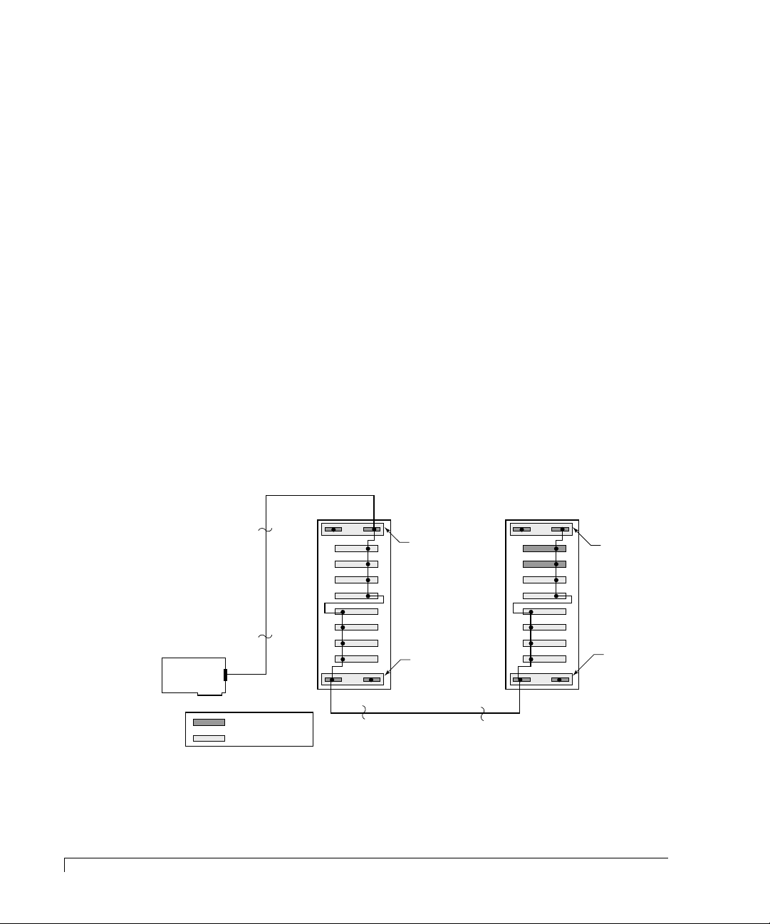
Two Single-Bus Enclosures
This configuration is similar to the “Single-Bus Enclosure” except that the
capacity is expanded with a second cabinet providing a total of fourteen driv es per
SCSI channel.
In this configuration a total of 16 SCSI IDs are available, one ID is consumed by
the AM RAID Controller , and ID 3 is tak en by the SAF-TE processor , lea ving the
fourteen remaining SCSI IDs available for the disk drives. Since the two CR8e
enclosures provide for sixteen drives, with only 14 IDs available two drive slots
will remain empty under this configuration.
CAUTION: Ensure that the power switch is in the OFF (O) position for both the
host system and the CR8e subsystem before connecting any cables.
1 Connect one end of a one meter data cable to the Channel #1 connector on
the AM RAID Controller.
2 Connect the other end of the data cable to the Channel #1 SCSI connector on
the upper or right side I/O Interface card.
NOTE: The Channel #1 connector located on the upper or right side I/O Interface
card is the active connector when the Single-Bus module is installed.
32
Fast Wide SCSI Mode
3 Locate the jumper cables. Connect one end of a jumper cable to the Channel #0
SCSI connector on the left side or lower I/O Interface car d in the first cabinet.
Page 45

Installation
4 Connect the other end of the jumper cable to the Channel #0 SCSI connector
on the left side or lower I/O Interface card in the second cabinet.
NOTE: SCSI termination is automatic and requires no user configuration. Refer
to “Termination” on page 21 for information on systems using DEC
Fault bus protocol.
5 Turn on the power to the CR8e. After the power-on self-test has completed,
Status and Channel Mode LEDs will be solid green.
6 Access the Options menu on the Operator Control Panel and choose the
SAFTE CHAIN ID selection. For each subsystem, identify which subsystem
will be the master cabinet and which will be the slave cabinet. (Generally, the
master cabinet will the subsystem connected to the controller.) Refer to
“SAFTE CHAIN ID” on page 50.
7 After setting the cabinet identifications you must power cycle the subsystem.
Observe normal power cycling precautions by waiting a minimum of five (5)
seconds before adding power again.
This will reset the SCSI IDs to a default setting that prevents a SCSI ID
conflict under normal conditions.
8 Power up your computer system and run your configuration program.
This completes the hardware installation.
Fast Wide SCSI Mode
33
Page 46
Installation
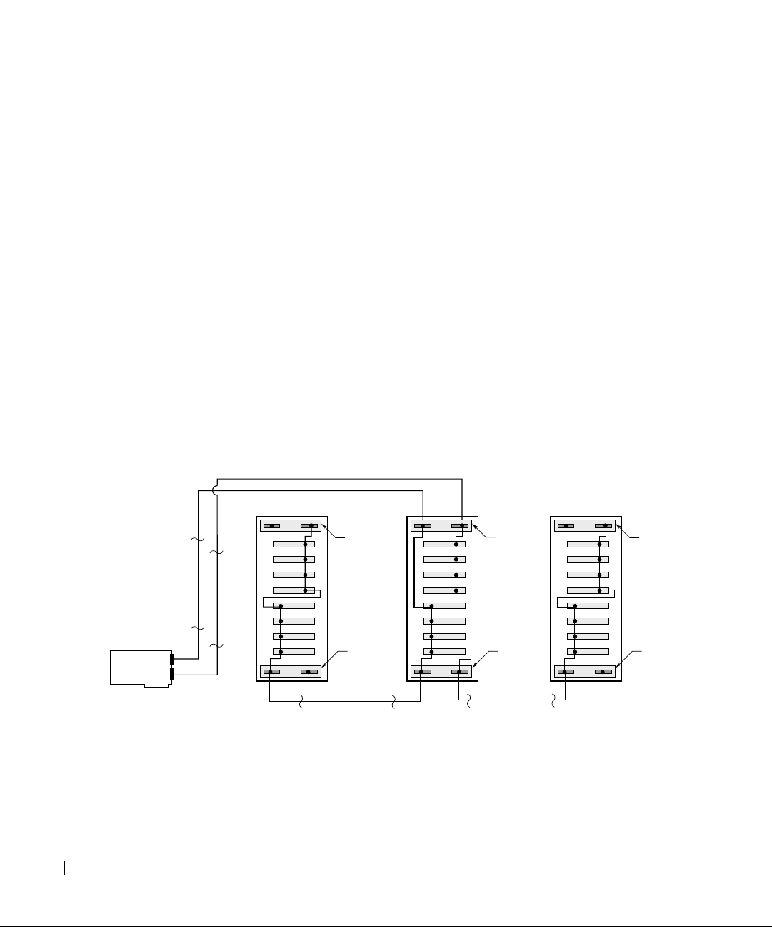
A Dual-Bus Enclosure with Two Single-Bus Enclosures
With this configuration you will be able to expand the capacity of each SCSI
channel of a Dual-Bus enclosure by adding a Single-Bus enclosure to each
channel. This provides up to twelv e drives per SCSI channel for a total capacity of
218 GB (using 18 GB disk drives) on each channel.
CAUTION: Ensure that the power switch is in the OFF (O) position for both the
host system and the CR8e subsystem before connecting any cables.
1 Connect one end of a one meter data cable to the Channel #1 connector on
the AM RAID Controller.
2 Connect the other end of the first data cable to the Channel #0 SCSI connector
on the right side or upper I/O Interface card.
3 Connect one end of the second data cable to the Channel #2 connector on the
AM RAID Controller.
4 Connect the other end of the second data cable to the Channel #1 SCSI
connector on the right side or upper I/O Interface card.
34
Fast Wide SCSI Mode
Ultra SCSI
RAID Controller
Ch 1
Ch 2
Ch 0
1 meter data cable
1 meter data cable
Rear View CR8e
Ch 0
TOP
Ch 1
I/O Interface
Card
I/O Interface
Card
with Single-Bus Module installed.
Ch 1
14-inch jumper cable
TOP
Ch 0
Rear View CR8e
with Dual-Bus Module installed.
Ch 0
Ch 1
Ch 1
14-inch jumper cable
TOP
Ch 0
I/O Interface
Card
I/O Interface
Card
Rear View CR8e
with Single-Bus Module installed.
Ch 0
Ch 1
5 Locate the jumper cables. Connect one end of one jumper cable to the
Channel #0 SCSI connector on the left side or lower I/O Interface card
installed in the Dual-Bus enclosure (master).
Ch 1
I/O Interface
Card
I/O Interface
Card
Page 47

Installation
6 Connect the other end of the first jumper cable to the Channel #0 SCSI
connector on the left side or lower I/O Interface card installed in the
Single-Bus enclosure (Slave #1).
7 Connect one end of a second jumper cable to the Channel #1 SCSI connector
on the left side or lower I/O Interface card installed in the Dual-Bus enclosur e
(master).
8 Connect the other end of the second jumper cable to the Channel #0 SCSI
connector on the left side or lower I/O Interface card installed in the
Single-Bus enclosure (Slave #2).
NOTE: SCSI termination is automatic and requires no user configuration. Refer
to “Termination” on page 21 for information on systems using DEC
Fault bus protocol.
9 Turn on the power to the CR8e. After the power-on self-test has completed,
Status and Channel Mode LEDs will be solid green.
10 Access the Options menu on the Operator Control Panel and choose the
SAFTE CHAIN ID selection. For each subsystem, identify which subsystem
will be the master cabinet and which will be the slave cabinets. (Generally,
the master cabinet will the subsystem connected to the controller.) Refer to
“SAFTE CHAIN ID” on page 50.
11 After setting the cabinet identifications you must power cycle the subsystem.
Observe normal power cycling precautions by waiting a minimum of five (5)
seconds before adding power again.
This will reset the SCSI IDs to a default setting that prevents a SCSI ID
conflict under normal conditions.
12 Power up your computer system and run your configuration program.
This completes the hardware installation.
Fast Wide SCSI Mode
35
Page 48

Installation
Other Configurations
There are many possible combinations of controllers and cabling schemes when
configuring the CR8e subsystem enclosures. The sample configurations in the
previous sections pro vide the basic configurations. However , the CR8e is based on
an open-architecture expandable subsystem and allows for customization to fit
your current or future needs.
Some other possible schemes within SCSI bus length limitations for both Ultra
Wide SCSI and Fast Wide SCSI are:
■ A 3-channel AM RAID Controller where two channels connect to a
dual-bus cabinet with two single-bus cabinets (Fast Wide). The third
channel of the controller can be connected to another Single-Bus enclosure
(Ultra Wide or Fast Wide).
■ A 3-channel AM RAID Controller with a Single-Bus enclosure connected
to each channel (Ultra Wide or Fast Wide).
■ A 3-channel AM RAID Controller with two Single-Bus enclosures
connected to each channel (Fast Wide).
■ A 3-channel AM RAID Controller with two Single-Bus enclosures
connected to two channels and a dual-bus cabinet connected to the third
channel (Fast Wide).
■ A 3-channel AM RAID Controller with four Single-Bus enclosures
connected to two channels and a dual-bus cabinet connected to the third
channel (Fast Wide).
■ A 2-channel AM RAID Controller with two Single-Bus enclosures
connected to each channel (Ultra Wide or Fast Wide).
■ A 2-channel AM RAID Controller with one Single-Bus enclosure
connected to each channel (Ultra Wide or Fast Wide).
36
Other Configurations
NOTE: For additional configuration options while operating under the Ultra
Wide SCSI mode, refer to the nStor Feature Card User’s Guide.
Page 49

3
Using the CR8e
In this chapter you will find information on the subsystem’s enclosur e notifications
systems, and the proper use and operation of the Operator Control Panel.
Notifications and Error Conditions
When the CR8e subsystem has powered applied, it will perform a power on selftest (POST) procedure. During the POST operation, in addition to the LED
notifications, you can also monitor the operation of the subsystem tests and the
subsystem component conditions all from the Operator Control Panel.
Power-On Self Test
During the diagnostic POST, a continuous tone will sound and the following will
be observed:
The Operator Control Panel will display “Testing ROM”, “NVRAM”, and
“SCSI Access” follo w ed by the startup mode scr een and the Status OK (default)
screen, provided no errors are detected. The Status Indicator LEDs will be as
follows:
• Fan Status LED will be solid amber and change to solid green
• Power Supply LED will be solid green
• Channel Mode LED will be solid amber and change to solid green
If no errors are detected, all of the Status Indicator LEDs will be illuminating
solid green.
37
Page 50

Using the CR8e
Firmware Error Conditions
NOTE:
Any of these failures listed below will gener ate the following: Channel Mode LED
blinks amber eight times and the alarm will sound eight tones. After the tones
have sounded the Channel Mode LED will change to green and normal oper ations
will be attempted. These error conditions indicate that the LEDs and alarm
functions may not be reliable.
If the errors occur constantly, the CR8e needs to be serviced. Contact nStor
Technical Support.
None of the following error conditions will compromise the data
integrity on the CR8e drives.
RAM Read/Write Failure - This error condition indicates that one or more
bytes of the microprocessor RAM failed a write/read test.
ROM Checksum Failure - This error condition indicates that the
microprocessor ROM failed to generate the proper checksum.
Register Read/Write Failure - This error condition indicates that one or mor e
of the microprocessor’s registers have become defective.
RAM Checksum Failure
If this error condition occurs, the Channel Mode LED will alternately blink green
and amber indefinitely . This indicates that the firmw ar e stored in the non-v olatile
RAM has become corrupted and new firmware data will need to be downloaded
from the SCSI bus to correct this problem. Contact nStor Technical Support.
38
Firmware Error Conditions
SCSI Bus Access Failure
If this error condition occurs, the Channel Mode LED will blink amber four times
and the speaker will sound four tones. This indicates that either the SCSI
controller failed to respond to a reset command or another device has control of
the SCSI bus.
Note that this may be caused by other devices having control of the bus at the
time the CR8e is powered ON. After the tones have sounded, there will be a two
second delay, and the microprocessor will again attempt to initialize the SCSI
controller. Turning the system OFF then ON again may help resolve this
condition. Normal operations will be impossible while the SCSI controller
remains unresponsive.
Page 51
Using the CR8e
All drive LEDs will illuminate solid green regardless of the error conditions. The
CR8e needs to be serviced if this error occurs consistently and is not cleared by
cycling the power on the CR8e. Contact nStor Technical Support.
NOTE:
The CR8e subsystem will not respond to the firmware if this error occurs.
LED Descriptions
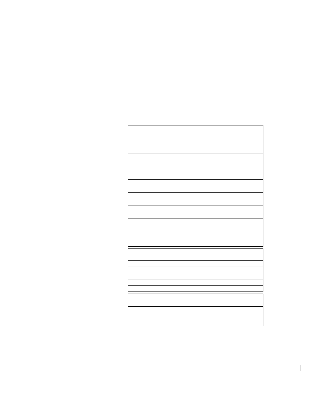
Use the following LED matrix to interpret the CR8e LEDs when the S AF-TE card
is installed and an accompanied SAF-TE compliant RAID controller is installed.
SAF-TE LED Matrix
STATUS LEDs
AT POWER UP Steady Green Steady Green
DRIVE READY
NOT ASSIGNED
DRIVE READY
ASSIGNED
HOT SPARE READY
ASSIGNED
DRIVE ERROR
NOT ASSIGNED
DRIVE ERROR
ASSIGNED
ARRAY CRITICAL
REMAINING GOOD DRIVES
HOT SPARE
REBUILD MODE
DRIVE MANUALLY
DISABLED
Blinking Green Steady Green
Steady Green Steady Green
Blinking Green Steady Green
Blinking Green Steady Amber
Blinking Amber Steady Amber
Steady Amber Steady Amber
Steady Amber Steady Amber
Blinking Amber Steady Amber
CHANNEL MODE LEDs
STATUS LEDs
HOT SPARE
ALL EMPTY BAYS
FAILED DRIVE
REBUILD MODE
CHANNEL MODE LEDs
ARRAY IS FAULT-TOLERANT
ARRAY IS IN REBUILD MODE
ARRAY HAS A FAILED DRIVE
FIRMWARE CHECKSUM ERROR Alternating Amber and Green
Steady GreenASSIGNED TO ARRAY
Blinking GreenUNASSIGNED DRIVE
Blinking Green
Off
Blinking Amber
Steady Amber (all drives)
Steady Green
Steady Amber
Steady Amber
LED Descriptions
39
Page 52
Using the CR8e
STATUS : OK
nStor CR8e
MENU ENTER ESCAPE
nStor
STARTING DUAL-BUS
CONFIGURATION
MENU ENTER ESCAPE
nStor
Startup Screen
(You will see either Dual-Bus or
Single-Bus, depending on the
configuration module installed.
Status OK Screen
Normal Screens
nStor CR8e
STATUS : HARDWARE
ERROR
MENU ENTER ESCAPE
nStor
MENU ENTER ESCAPE
STATUS : HEAT
THRESHOLD EXCEEDED
nStor CR8e
nStor
Hardware Error Screen
Temperature Exceeded Screen
Abnormal Screens
Operator Control Panel
In this section you will find an explanation of the Operator Control Panel screen
displays, as well as a description and subsequent procedur es for using each of the
OCP menu functions.
Startup Screens
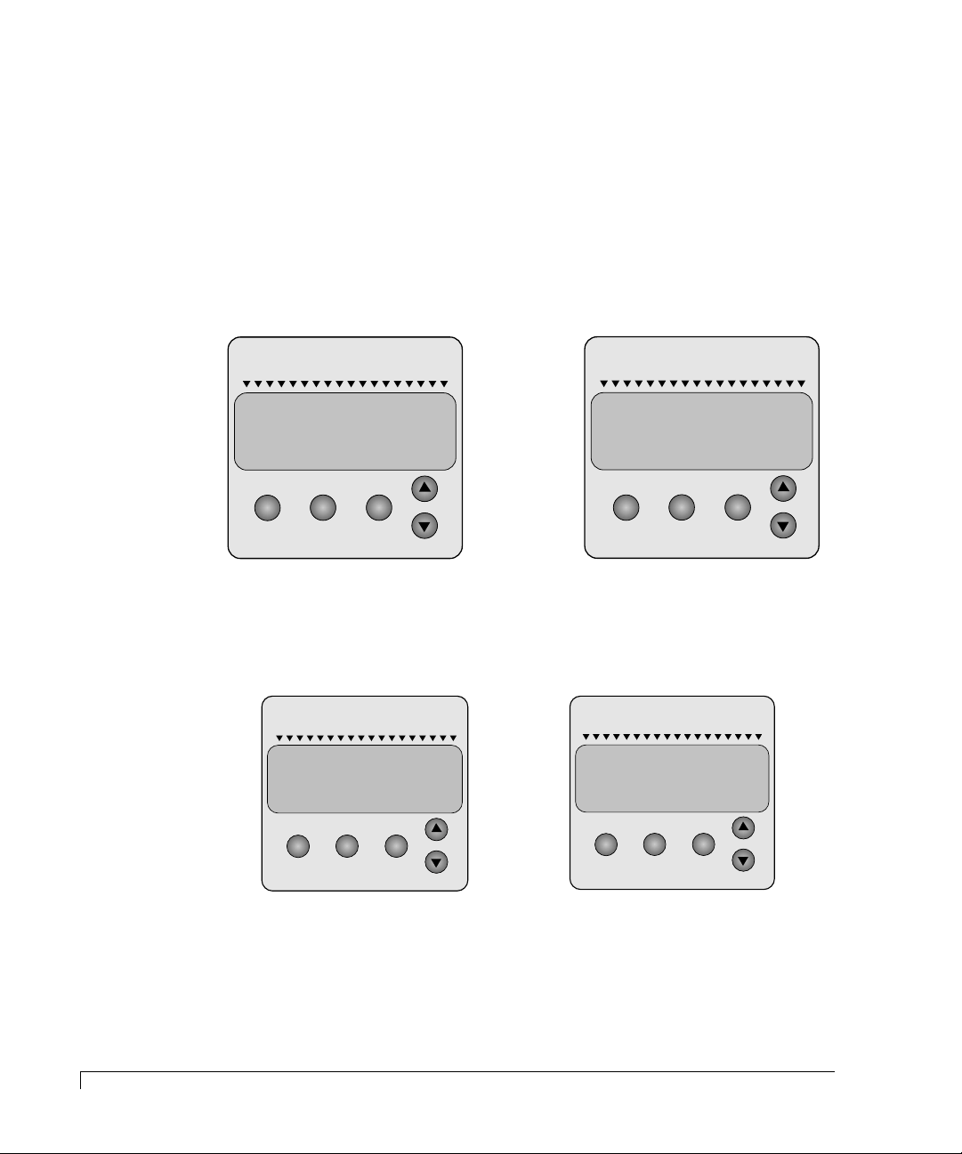
The following are sample screens that could occur during the startup POST
operation for normal conditions and abnormal conditions:
40
Operator Control Panel
If a subsystem error occur during the startup, you will hear a continuous tone
from the alarm. Access the Component Status Menu to identify the suspected
failed component.
Page 53
Using the CR8e
Power Supply Error Conditions
During normal operation, anytime one of the required number of power supplies
becomes inoperative, you will hear a continuous alarm and a warning message
will appear on the display. This message is simply a notification that the state of
the power system is no longer redundant. Use the Component Status menu to
determine which power supply has failed and identify the failed unit by the
absence of its “DC Good” LED on the PSU. Replace the failed component to
return the subsystem to a redundant state.
If you install five (5) or more disk drives and only have two (2) power supplies
installed, an alarm will sound. The Power Supply LED will illuminate steady
amber and the OCP display will indicate “Non-Redundant Power.” Install a third
power supply and the error message will clear follo w ed b y the Power Supply LED
returning to a steady green. For more information see Installing the Third Power
Supply on page 19.
Subsystem Status Icon
A feature of the CR8e OCP is the “at-a-glance” animated icon that appears to
indicate subsystem status. The icon will appear at the Main menu screen after 30
seconds of no OCP input activity and provides an “at-a-glance” look at system
status. The icon will be located where the cursor normally appears.
The animated icon will have a “happy” face and looks “left and right”, if all the
systems are operating normally. If an abnormality occurs within the subsystem,
the icon will change to a “sad” face requesting your attention.
Happy Icon
(systems nominal)
Sad Icon
(systems abnormal)
Power Supply Error Conditions
41
Page 54
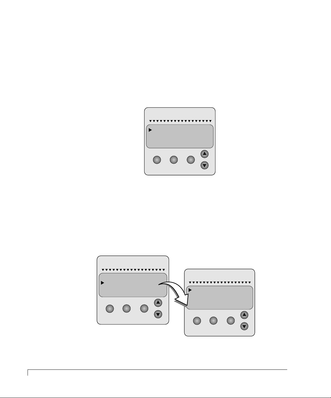
Using the CR8e
MENU ENTER ESCAPE
HARDWARE MENU
OPTIONS MENU
TURN OFF ALARM
nStor
MENU ENTER ESCAPE
OPTIONS MENU
TURN OFF ALARM
HARDWARE MENU
nStor
MENU ENTER ESCAPE
CONFIGURATION INFO
POST RESULTS
COMPONENT STATUS
nStor
INTERNAL TEMP
Main Menu
From the Main Menu selection the following options are available:
■ Turn off the audible alarm
■ Select the hardware menu
■ Select the options menu
To access the Main menu, press the Menu button. Use the up and down arrow
buttons to make your selection and press the Enter button.
Hardware Menu
42
Main Menu
From the Hardware Menu selection the following options are available:
■ Component Status
■ Configuration Info
■ POST Results (Power-On Self Test)
■ Internal Temp
Page 55
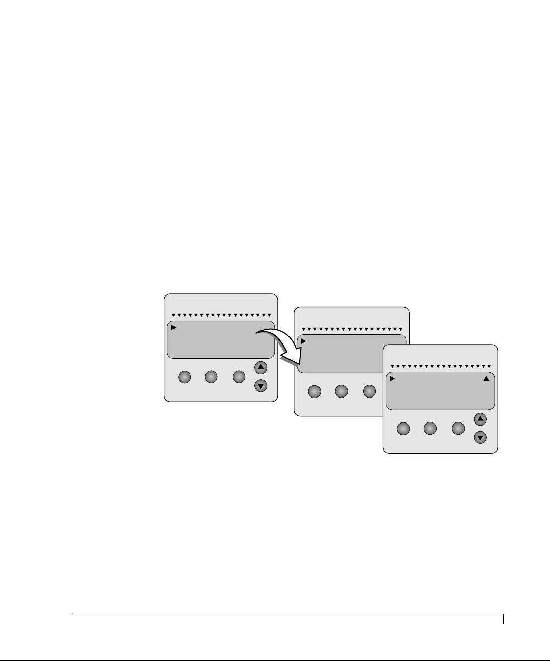
Using the CR8e
Component Status
The Component Status menu provides a view of the power supplies and fans
installed in the CR8e and their current status. Component status can be either
OK, Missing, or Failed.
1 If you receive a Hardware Error, access the Main menu and choose the
Hardware Menu.
2 Use the up/down arrow buttons to select Component Status and press the
Enter button.
3 Use the up/down arrow buttons scrolling to view the complete list of the
components.
Fan speeds are expressed in % of RPM. The bus configuration will be
displayed for the type of Configuration Module you have installed.
4 Press the Escape button to return to the pre vious menu or the Menu button to
return to the Main “Status OK” screen.
nStor
COMPONENT STATUS
CONFIGURATION INFO
POST RESULTS
INTERNAL TEMP
MENU ENTER ESCAPE
nStor
PWR SPLY 1...OK
PWR SPLY 2...OK
PWR SPLY 3...MISSING
FAN 1...........FAILED
MENU ENTER ESCAPE
nStor
FAN 2...........OK
FAN 1 SPEED..79%
FAN 2 SPEED..79%
BUS CONFIG...SINGLE
MENU ENTER ESCAPE
Configuration Info
This selection provides information about the subsystem’s configuration
including such items as the installed feature cards and firmware information.
NOTE:
Slot “x” Cards are the feature cards located on the subsystem rear panel.
Slot 1 is the lower/left feature card slot and slot 2 is the upper/right
feature card slot.
Main Menu
43
Page 56
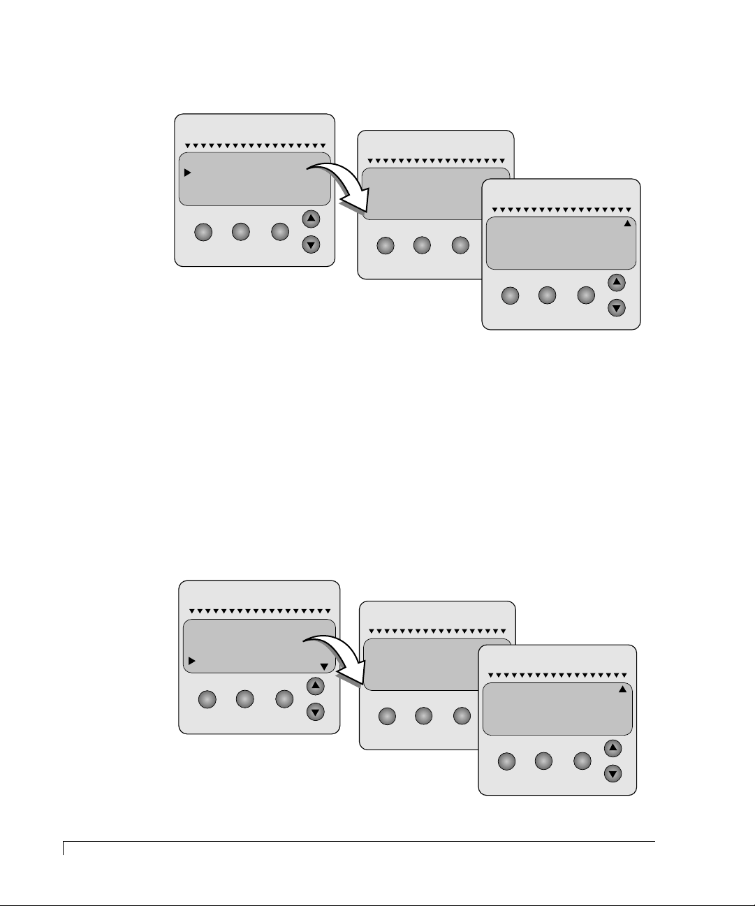
Using the CR8e
MENU ENTER ESCAPE
INTERNAL TEMP
COMPONENT STATUS
CONFIGURATION INFO
POST RESULTS
nStor
MENU ENTER ESCAPE
SLOT 2 CARD:
SLOT 1 CARD:
I/O INTERFACE
nStor
PROD: CR8L SAF-TE
MENU ENTER ESCAPE
RAM REVISION: 0.23
ROM REVISION: 1.05
ID: FFFFFFFFh
I/O INTERFACE
nStor
1 To view the current enclosure configuration, access the Main menu and
choose Hardware Menu.
2 Use the up/down arrow buttons to select Configuration Info and press the
Enter button.
3 Use the up/down arrow buttons scrolling to view the current configuration.
4 Press the Escape button to return to the pre vious menu or the Menu button to
return to the Main “Status OK” screen.
44
Main Menu
POST Results
This screen provides a list of the diagnostics performed during the POST pr ocedure .
If an error has occurred it will be display ed here in addition to the notification
provided by the LEDs and alarms, see Power-On Self Test on page 37.
nStor
COMPONENT STATUS
POWER STATUS
FW REVISION
POST RESULTS
MENU ENTER ESCAPE
nStor
ROM CHKSUM ..OK
RAM CHKSUM ..FAILED
RAM R/W. ......OK
SCSI BUS 0 ...OK
MENU ENTER ESCAPE
nStor
RAM R/W. ......OK
SCSI BUS 0 ....OK
SCSI BUS 1 ....OK
PROCESSOR.....OK
MENU ENTER ESCAPE
Page 57
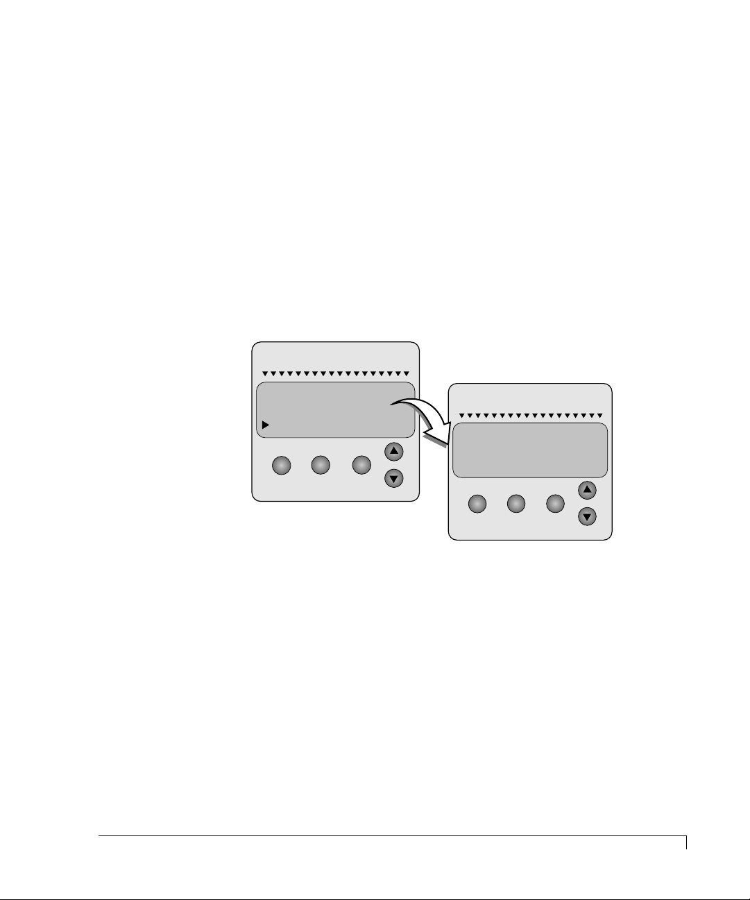
Using the CR8e
1 To view the POST results, access the Main menu and choose Hardware Menu.
2 Use the up/down arrow buttons to select Post Results and press the Enter
button.
3 Use the up/down arrow buttons scrolling to view the complete POST results
lists.
4 Press the Escape button to return to the pre vious menu or the Menu button to
return to the Main “Status OK” screen.
Internal Temp
This screen displays the current internal enclosure temperature (highest of the
two sensors). To change the temperature threshold of the monitoring system, see
Heat Threshold on page 49.
nStor
COMPONENT STATUS
CONFIGURATION INFO
POST RESULTS
INTERNAL TEMP
nStor
CABINET INTERNAL
TEMPERATURE
75°F / 24°C
MENU ENTER ESCAPE
MENU ENTER ESCAPE
1 To view the cabinet internal temperature, access the Main menu and choose
Hardware Menu.
2 Use the up/down arrow buttons to select Internal Temp and press the Enter
button.
3 Press the Escape button to return to the pre vious menu or the Menu button to
return to the Main “Status OK” screen.
Main Menu
45
Page 58
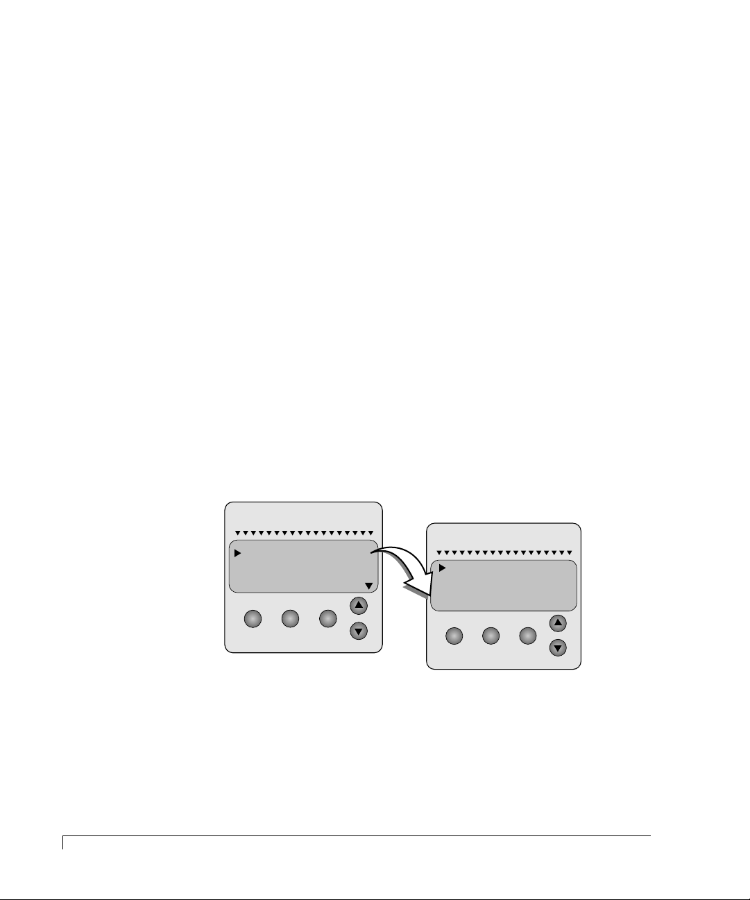
Using the CR8e
MENU ENTER ESCAPE
SCSI ID MENU
HEAT THRESHOLD
SAFTE CHAIN ID
CHANGE PASSCODE
nStor
MENU ENTER ESCAPE
nStor
RESET DEFAULT IDS
SET UPPER SLOT IDS
SET LOWER SLOT IDS
SET SAFTE ID
Options Menu
From the Options Menu the following are available:
■ SCSI ID Menu
■ Heat Threshold
■ SAFTE Chain ID
■ Change Passcode
■ Unlock Options
SCSI ID Menu
From the SCSI ID Menu you can set SCSI IDs for drives attached to each of the
SCSI channels (lower slot and upper slot), and set the CR8e SAF-TE processor ID
(upper or lower bus if a Dual-bus module is installed).
You can manually set SCSI IDs for each group of drives from a pre-defined table of
IDs, see JP4 (SCSI ID Settings) on page 74 for a list of the possible ID combinations.
The SCSI IDs which are currently set will be flashing. The IDs will be assigned
sequentially beginning with the lowest device in the group.
NOTE:
Drive SCSI IDs cannot be set individually.
1 To manually set the SCSI IDs for the drive sets found in the upper or lower
slots, access the Main menu and choose Options Menu.
2 Use the up/down arrow buttons to select SCSI ID Menu and press the Enter
button.
3 Use the up/down arrow buttons to select either the Lower or Upper drive slot
IDs, or the SAFTE ID, and press the Enter button.
46
Options Menu
Page 59
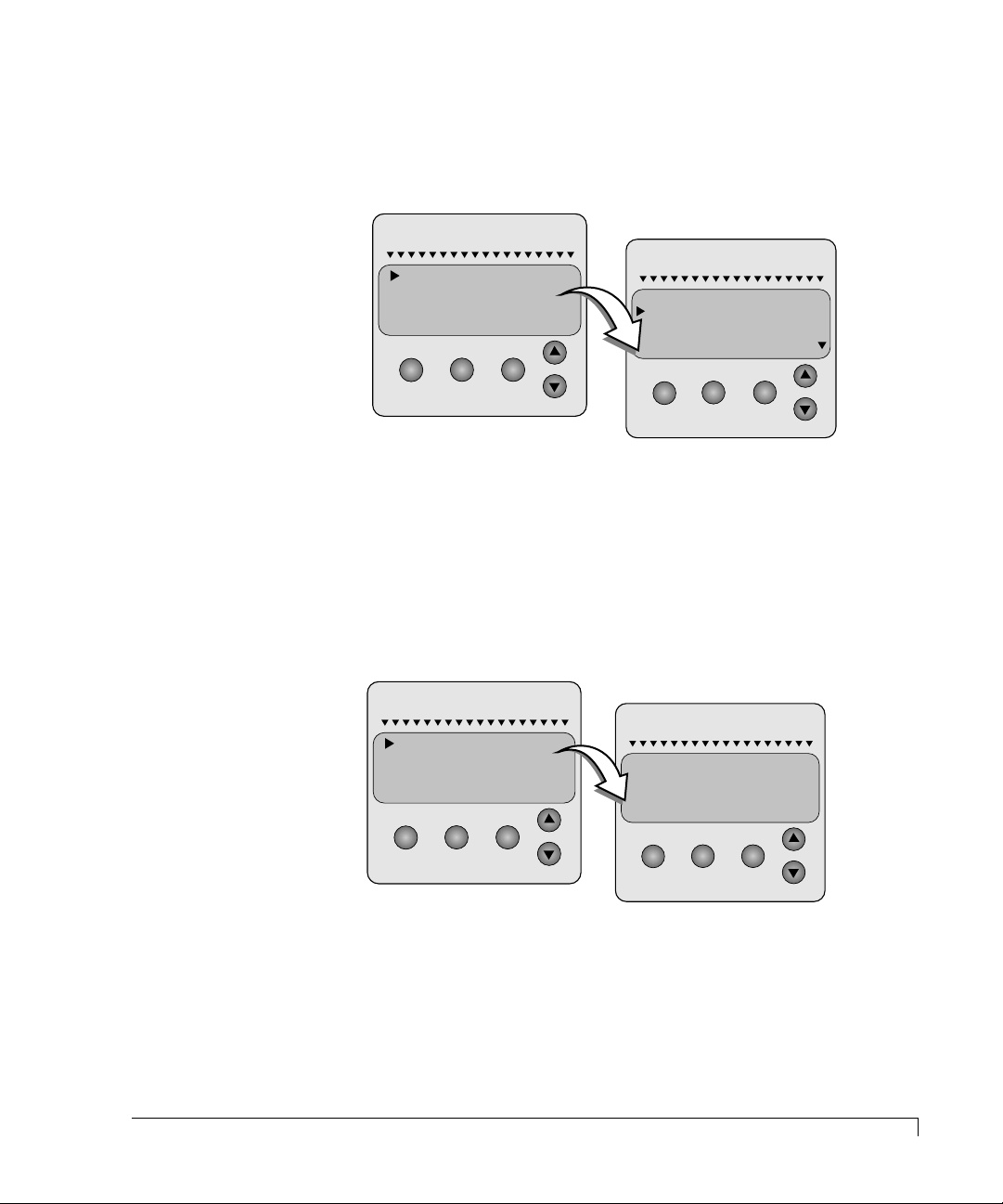
Using the CR8e
MENU ENTER ESCAPE
nStor
RESET DEFAULT IDS
SET UPPER SLOT IDS
SET LOWER SLOT IDS
SET SAFTE ID
MENU ENTER ESCAPE
0 1 2 3
0 1 2 4LOWER 4
4 5 6 7
4 5 6 8
5 6 7 8
nStor
MENU ENTER ESCAPE
SET ID ON UPPER BUS
SET ID ON LOWER BUS
nStor
MENU ENTER ESCAPE
ENTER TO SET NEW ID
ESC TO EXIT
PROCESSOR ID: 3
ARROWS CHANGE ID
nStor
4 Use the up/down arrow buttons to make your SCSI ID group selection and
press the Enter button.
Note the flashing set of IDs, if present. These will be the group currently
configured.
5 Press the Escape button twice or the Menu button to return to the Main “Status
OK” screen, then power cycle the host computer and CR8e subsystem.
NOTE:
You must power cycle the subsystem for the SCSI IDs changes to take
effect.
To change the SAF-TE card SCSI ID, follow the five steps above, except select “Set
SAFTE ID” in step 3 and choose from “Set ID on Lower Bus” or “Set ID on
Upper Bus” in step 4. Use the up/down arrow buttons to change the ID value.
Since the subsystem is available in either a split SCSI bus design or as a single
SCSI bus, you can set the SAF-TE card SCSI ID for each bus if a conflict is
occurring. The default setting is SCSI ID 3 for each bus. The setting for SCSI
ID “OB” indicates Off Bus and is generally used when the subsystem is
installed in a “Slave” subsystem in a Master/Slave environment.
Options Menu
47
Page 60
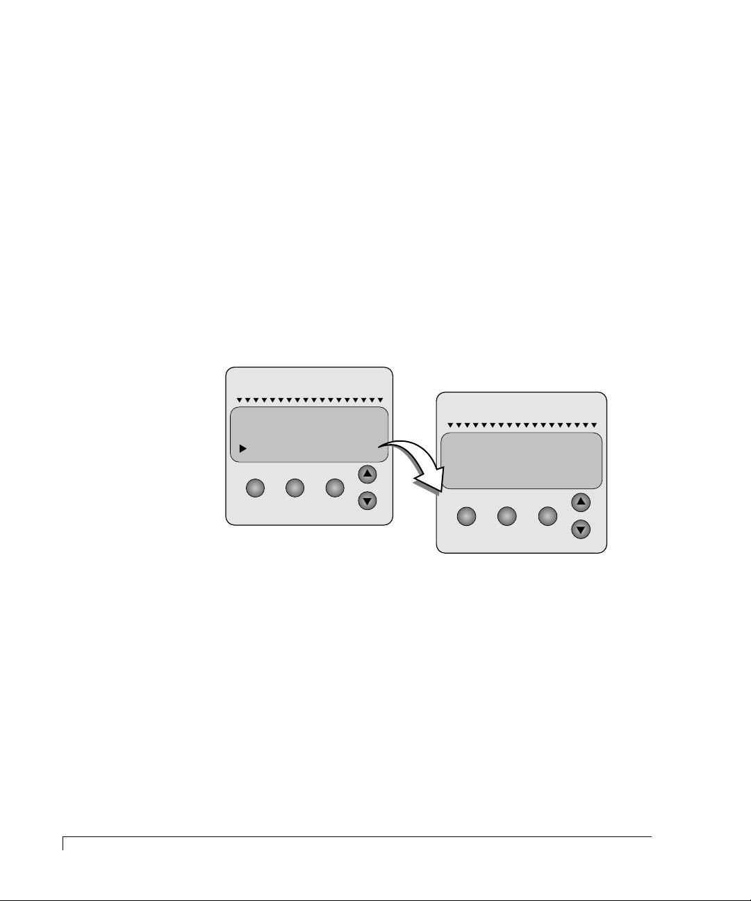
Using the CR8e
MENU ENTER ESCAPE
RESET DEFAULT IDS
nStor
SET UPPER SLOT IDS
SET LOWER SLOT IDS
SET SAFTE ID
MENU ENTER ESCAPE
DUAL BUS MODE
ALL SCSI IDS SET TO
EFFECT CHANGES)
(CYCLE POWER TO
nStor
NOTE:
When the SAF-TE card is set to off bus, LEDs and other error reporting
are not driven by the subsystem’s off bus SAF-TE card, but are reported
and controlled from the “Master” subsystem’s SAF-TE card.
Reset Default IDs Selection
Choosing the “Reset Default IDs” option will r eset all subsystem SCSI IDs to their
factory default settings.
The default drive ID settings when a dual-bus module is installed are 0, 1, 2, and
4 for both the upper and lower drive groups.
The default drive ID settings when a single-bus module is installed are 0, 1, 2, 4,
5, 6, 8, and 9.
The default SCSI ID for the SAF-TE card is ID 3. SCSI ID 7 is reserved for the
host bus adapter.
48
Options Menu
NOTE:
You must power cycle the subsystem for the SCSI IDs changes to take
effect. Also be sure to power cycle the host computer. If a PCI-based
RAID Controller is being used and the host is not power cycled, it will
“kill” all drives in the array.
1 To reset the SCSI IDs, access the Main menu and choose Options Menu.
2 Use the up/down arrow buttons to select SCSI ID Menu and press the Enter
button.
3 Use the up/down arrow buttons to select RESET DEFAULT IDS.
4 Press the Escape button twice to return to the Main “Status OK” screen, then
power cycle the host computer and CR8e subsystem.
Page 61
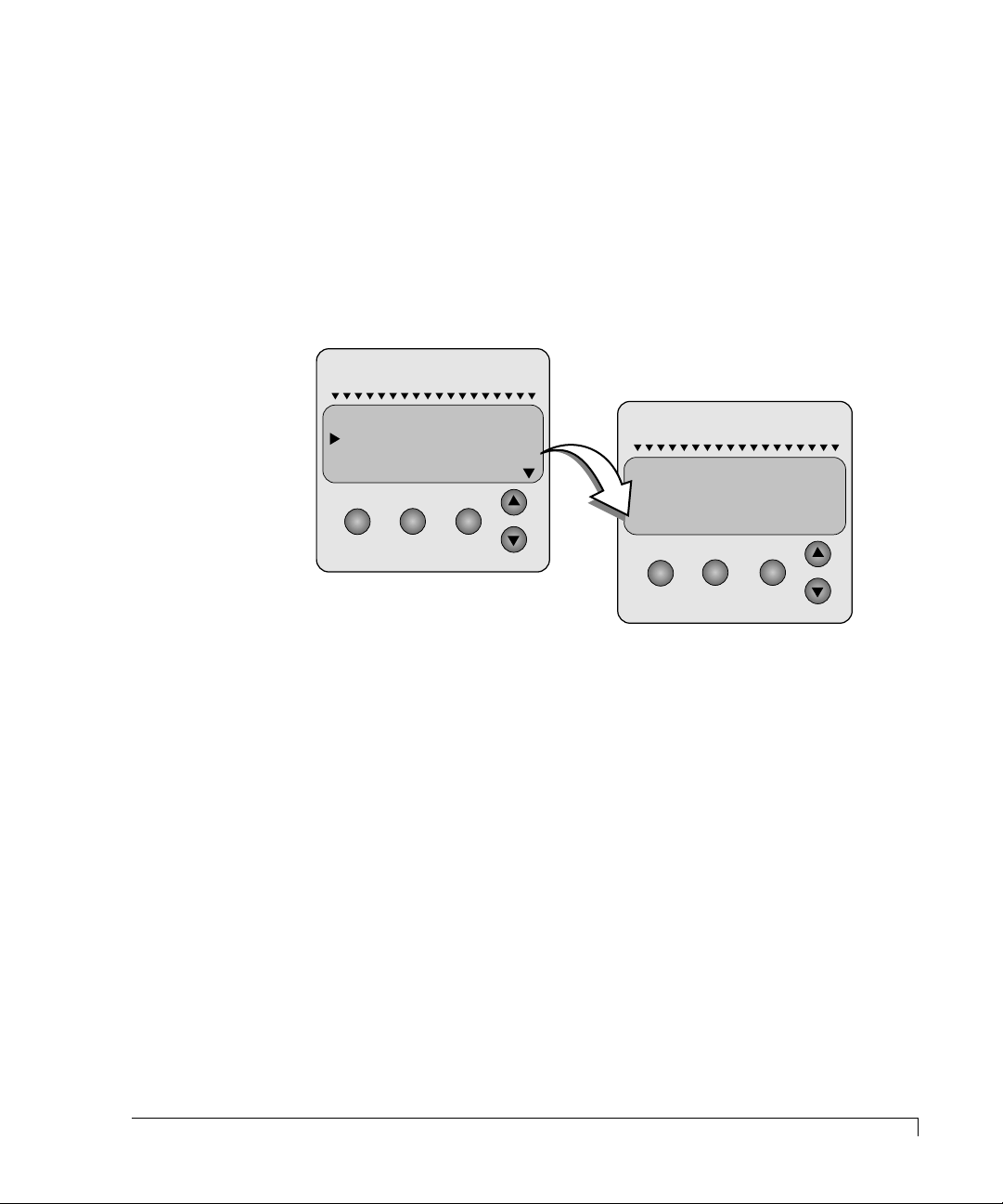
Heat Threshold
Using the CR8e
NOTE:
The Heat Threshold value is pre-set at the factory and should not be
changed unless directed by nStor Technical Support. The default setting
is 116°F/47.°C.
Choose the Heat Threshold Menu to change the temperature value for the
thermal monitoring system. If the temperature exceeds the value set here, a
“Temperature Threshold Exceeded” screen will appear, see Internal Temp on
page 45.
nStor
SCSI ID MENU
HEAT THRESHOLD
SAFTE CHAIN ID
CHANGE PASSCODE
MENU ENTER ESCAPE
nStor
ARROWS TO CHANGE
ENTER TO SET
ESC TO EXIT
116°F / 47°C
MENU ENTER ESCAPE
1 Use the up/down arrow buttons to select Heat Threshold and press the Enter
button.
2 Using the up/down arrow buttons, change the temper atur e threshold setting.
The up arrow button will increase the temperature and the down arrow
button will lower the temperature threshold. The temperature value will
change by 2°C increments.
3 Press the Enter button the set the new temperature value.
4 Press the Escape button twice or press the Menu button to return to the Main
“Status OK” screen, then power cycle the host computer and CR8e
subsystem.
Heat Threshold
49
Page 62
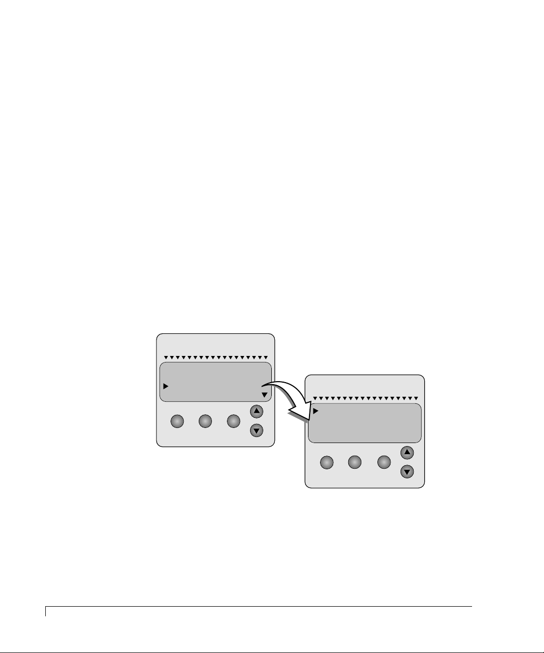
Using the CR8e
SAFTE CHAIN ID
This option allows the administrator to establish the intercabinet SAF-TE
communication to support a master and slave cabinets. The master cabinet can
report component failure for both the master cabinet and up to two slave cabinets
to the AdminiStor Storage Management software. Each cabinet’s individual OCP
will function normally for that cabinet’s components.
Once the slave cabinets hav e been established, the administrator must use the slav e
cabinet’s OCP to manually take that slave cabinet SAF-TE card off bus, refer to
“SCSI ID Menu” on page 46.
1 Choose the SAFTE CHAIN ID selection and press the Enter button.
2 Use the up/down arrow buttons and choose between the options: None,
Master, Slave 1, and Slave 2, then press the Enter button.
NOTE:
Choose “NONE” when the cabinet is used in a stand-alone configuration
or the master/slave option is not desired.
3 You will be prompted to cycle the power on the CR8e for the changes to take
effect.
nStor
SCSI ID MENU
HEAT THRESHOLD
SAFTE CHAIN ID
CHANGE PASSCODE
MENU ENTER ESCAPE
nStor
NONE
MASTER
SLAVE 1
SLAVE 2
MENU ENTER ESCAPE
50
SAFTE CHAIN ID
Page 63
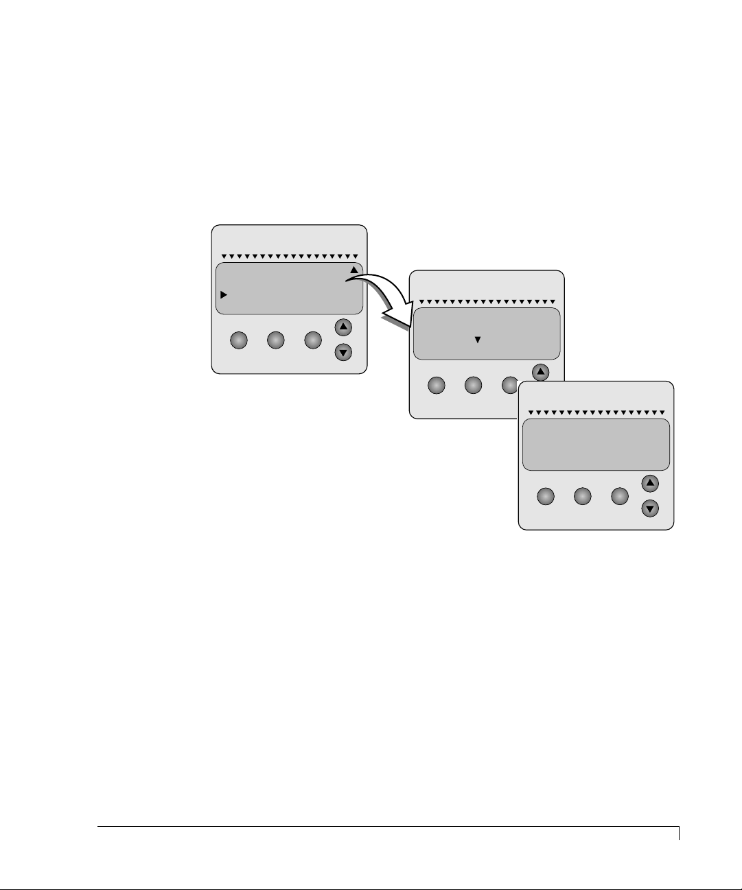
Using the CR8e
Change Passcode
This option allows the administrator to create or change a passcode that will
protect access to all the items under the selections SCSI ID Menu, Heat
Threshold, and Change Passcode.
1 Use the up/down arrow buttons to select Change P asscode and pr ess the Enter
button.
nStor
HEAT THRESHOLD
SAFTE CHAIN ID
CHANGE PASSCODE
UNLOCK OPTIONS
nStor
ENTER NEW PASSCODE
MENU ENTER ESCAPE
MENU ENTER ESCAPE
0 0 0 0
nStor
PASSCODE CHANGED
(ESCAPE TO CONTINUE)
MENU ENTER ESCAPE
2 Use the up/down arrow buttons to change the code v alue (0-9) and the Enter
button to move from one field to the next.
3 Press the Enter button after you have made your selections.
4 You will be prompted to press the Escape button after the passcode has been
modified to enable the change to take affect. The default code is “0000.”
NOTE:
The passcode lock will not take effect until you have returned to the
Main screen displaying “Status OK.”
Change Passcode
51
Page 64
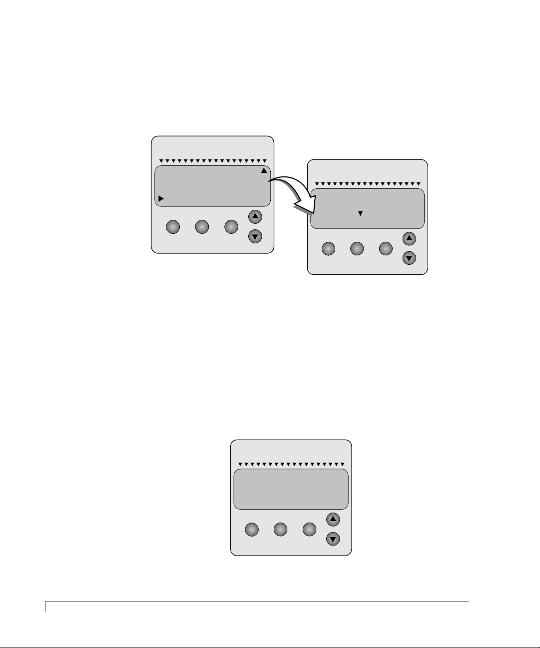
Using the CR8e
Unlock Options
This option allows the administrator to unlock the items found under the SCSI ID
Menu, Heat Threshold, and Change Passcode selections. This enables the user to
change these values and protects these values from being changed by those not
authorized to do so.
nStor
HEAT THRESHOLD
SAFTE CHAIN ID
CHANGE PASSCODE
UNLOCK OPTIONS
MENU ENTER ESCAPE
nStor
ENTER 4 DIGIT
PASSCODE
0 0 0 0
MENU ENTER ESCAPE
1 To change the Unlock Options, access the Main menu and choose Options
Menu.
2 Use the up/down arrow buttons to change the code v alue (0-9) and the Enter
button to move from one field to the next.
3 Press the Enter button after you have made your selections.
You will be prompted that the SCSI ID Menu options are unlock ed until you have
cycled the menus back to the default “Status OK” screen. An “unlock” icon will
appear in place of the cursor while the options remain unlocked.
nStor
52
Unlock Options
OPTIONS WILL REMAIN
UNLOCKED UNTIL YOU
RETURN TO THE
DEFAULT SCREEN
MENU ENTER ESCAPE
Page 65
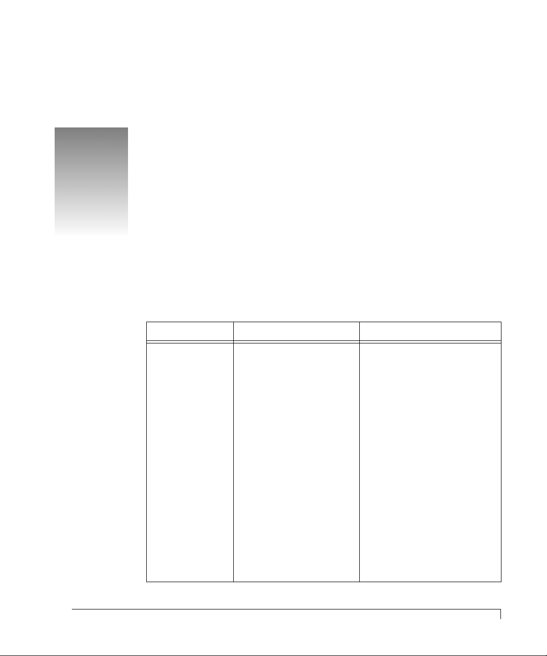
4
Troubleshooting
This chapter provides solutions for some of the problems you may encounter
while using the CR8e subsystem.
Common Enclosure Problems
Symptom Reason Solution
Fails to power on. Power cord not connected
properly.
Power not available at the
outlet.
Power switch not in the
proper position.
Faulty fuse.
Faulty power cord.
Verify that the power cord is
properly connected to the power
module.
If the CR8e is plugged into a
three-hole grounded outlet,
verify if power to the outlet has
been interrupted. This can be
accomplished by testing the
outlet with a known working
appliance, like a lamp.
Be sure that the power switch is
in the “ON” position, labeled “I”.
Replace fuse, see Replacing a
Fuse on page 62.
Replace power cord.
If the CR8e is not responding,
contact nStor Technical
Support.
53
Page 66
Troubleshooting
Symptom Reason Solution
Operator Control
Panel display
indicates
“Hardware Error.”
LED and audible
alarms indicate
the system failed
the diagnostic test.
Operator Control
Panel display
indicates cabinet
temperature
threshold has been
exceeded.
Possible component failure. From the Operator Control
Panel, “Hardware Menu” from
the Main Menu and select
“Component Status.” Scroll
down through the list to locate
the failed component. Follow the
procedures in the Maintenance
chapter to replace the failed
component.
Power-on self-test failed. From the Operator Control
Panel, “Hardware Menu” from
the Main Menu and select
“POST Results.” Scroll down
through the list to locate the
failed component, see Power-On
Self Test on page 37.
Cooling fan failure.
From the Operator Control
Panel, “Hardware Menu” from
the Main Menu and select
“Component Status.” Scroll
down through the list to locate
the failed component. Follow the
procedures in the Maintenance
chapter to replace the failed
component.
54
Common SCSI Bus Problems
Temperature threshold too
low.
Cooling fan vent blocked.
Inadequate ventilation
around the CR8e.
Change the temperature
threshold value, see Heat
Threshold on page 49.
Examine the cooling fan vents
for blockage and clear.
The location chosen for the
CR8e probably has poor air
circulation. Choose a better
location.
Common SCSI Bus Problems
SCSI Bus problems can usually be attributed to cabling issues or faulty I/O
Interface cards. Refer to the chart on the following page to review troublshooting
and fault isolation procedures to assist you in identifying the suspect component.
Page 67
Troubleshooting
SCSI Bus Symptom Probable Cause Solution
SCSI Bus hangs, SCSI
Bus excessive retries,
and/or drives drop
offline.
Faulty connectivity.
Faulty I/O Interface card.
Re-check the cables to the I/O
Interface card and host adapter.
Depending on how many
subsystem are connected on the
SCSI bus, you will need to
perform some fault isolation.
If all the drives on one bus are
offline, start with the subsystem
furthermost out on the chain.
Disconnect the data cable. If the
remaining drives return to a
normal state it indicates that
the isolated subsystem has the
faulty component.
If this does not return the
remaining drives to a normal
state, continue removing each
data cable on that bus until the
first subsystem is the remaining
subsystem.
If you had to remove all the data
cables up to the first subsystem
and the problem is still not
resolved, this could indicate
that the I/O Interface card in
the first subsystem is the
suspect faulty card. Use one of
the cards from the previous
subsystems or a “new” known
good card. This should return
the subsystem bus to a normal
condition.
Note: A return to a normal
condition is indicated by the
drives coming back online.
After the faulty card is
replaced, begin re-connecting
the data cables on the
remaining I/O Interface cards
noting the bus remains in a
normal state.
Common SCSI Bus Problems
55
Page 68
Troubleshooting
Common Problems and Interpreting the LED Indications
LED Status Reason Solution
Status Indicator
LEDs not
functioning
properly.
A specific drive’s
Status LED is
blinking amber
and the Channel
Mode LED is
steady amber.
A specific drive’s
Status LED is
blinking amber,
the remainder of
the drive’s Status
LEDs in that array
are steady amber,
and the Channel
Mode LED is
steady amber.
A specific drive’s
Status LED is OFF
and the Channel
Mode LED is
steady amber.
A specific drive’s
Status LED is
blinking green and
the Channel Mode
LED is steady
green.
SCSI data cable not properly
connected.
An assigned drive has failed.
The CR8e is in a non-fault
tolerant mode.
An assigned drive has failed.
The CR8e is in a non-fault
tolerant mode and a rebuild
operation is in progress.
The disk drive is missing.
The CR8e is in a non-fault
tolerant mode.
A drive has not been
assigned into an array or the
drive is a hot spare, however
it is in a ready state.
Verify that the SCSI data cable is
properly connected to the CR8e
SCSI-2 connector and to the
controller card.
Replace the disk drive and begin
rebuilding the array, see
Replacing a Disk Drive on
page 57.
Replace the failed disk drive
(Drive’s Status LED blinking
amber).
Insert a disk drive and begin an
array rebuild, see Replacing a
Disk Drive on page 57.
Assign the drive to an array,
refer to the nStor AM RAID
Utilities User’s Guide.
56
Common Problems and Interpreting the LED Indications
Page 69

5
Maintenance
In this chapter you will find the maintenance procedures to replace individual
components, as well as the entire subsystem enclosure.
Replacing a Disk Drive
CAUTION: Drives and printed circuit board components are sensitive to
electrostatic discharge. To prevent operating failure or damage,
observe the following: Establish a ground for yourself by using the
wrist grounding strap, or by touching the metal chassis prior to
handling or installing the drives or printed circuit board components.
NOTE: There is no need to power OFF the CR8e or the computer system. The
drives are hot swappable.
1 Unlock and open the door on the CR8e cabinet.
1 Identify the failed drive using the Status LEDs and the Fault LED.
2 Using your thumbs, apply a slight pressure outward to release the drive latch
clips, unlocking the failed drive and remove the drive.
3 Remove your new disk drive from the shipping carton and inspect the
shipment. Remove the anti-static protective packaging.
4 Holding the drive by its edges, locate the Drive Latching Clips and pull out on
the latches to unlock them. The Drive Latching Clips are placed in the locked
position for shipping purposes.
57
Page 70
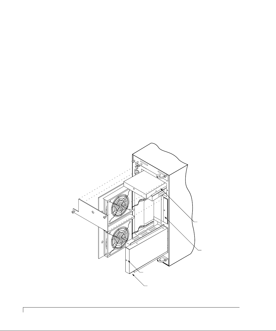
Maintenance
Power Supply #1
“DC Good” LED
Power Supply #2
Power Supply #3
5 Insert the drive into the drive bay b y aligning its r ails into the drive bay slots,
component side toward the right (rack) or down (tower). Seat the drive by
applying pressure with your thumb to the front of the drive.
6 Press the Drive Latching Clips until they “snap” into place.
7 Using the packaging materials from the replacement disk drive, repackage the
failed drive and return it to nStor Corporation, refer to the nStor Resource
Guide for information on “Obtaining a Return Material Authorization.”
Replacing a Power Supply
CAUTION: Power supplies must be replaced by qualified service personnel only.
1 Using the Operator Control Panel, identify the failed power supply.
Select “Hardware Menu” from the Main Menu and choose “Component
Status.” For more information, refer to “Component Status” on page 43.
58
Replacing a Power Supply
Page 71

Maintenance
NOTE: When locating the failed power supply, the “DC Good” LED will be OFF.
2 Using a flat-blade screwdriver, loosen the rear door access screw. Open the
door to gain access to power supplies #1 and #2.
If you are replacing the #3 power supply, loosen the two PSU Cover Plate
screws. Remove the cover plate and skip to step 3.
3 Grasp the handle of the subject power supply and pull the supply out of the
CR8e enclosure.
NOTE: The orientation of the power supply being removed. This will facilitate
the installation of the replacement supply.
4 Remove the new power supply from the shipping carton and inspect the
shipment. Save the packaging material.
5 Slide the new power supply into the cabinet until it reaches its locked
position.
NOTE: Orient the power supply in the same manner as the removed power
supply. (Air slots in the PSU case face toward the center of the cabinet.)
The new power supply’s LED should illuminate.
6 Close the rear door panel. The door has a latch mechanism that holds the
door in the open position. Squeeze the latch to release the door allowing it to
be closed.
If you are replacing the #3 power supply, re-install the PSU Cover Plate and
then re-secure the power cord retainer.
7 Using the packaging materials from the replacement po w er supply, repackage
and return it to nStor Corporation, refer to the nStor Resource Guide for
information on “Obtaining a Return Material Authorization.”
Replacing a Power Supply
59
Page 72
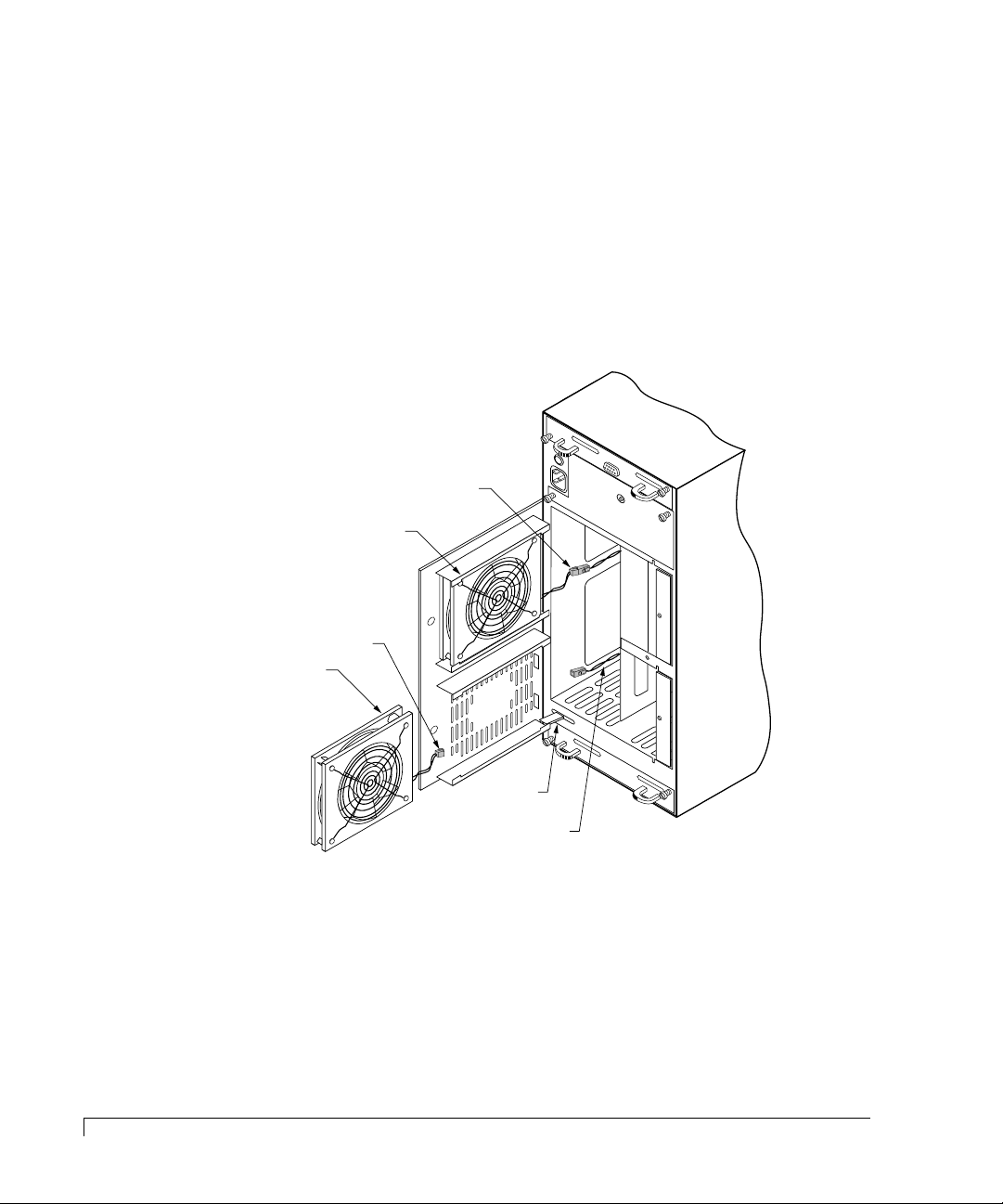
Maintenance
Replacing the Cooling Fans
CAUTION: Cooling fans must be replaced by qualified service personnel only.
NOTE: There is no need to power off the CR8e or the computer system. The
cooling fans are hot swappable.
1 Use the Operator Control Panel to identify the failed fan, refer to the
illustration below to locate the components.
Select “Hardware Menu” from the Main Menu and choose “Component
Status.” For more information, refer to “Component Status” on page 43.
Fan #2
Power Cable
Fan #2
60
Replacing the Cooling Fans
Fan #1
Power Cable
Fan #1
Door Latch
Fan #1
Power Cable
You may need to scroll through the list with the arrows buttons to locate the
failed component.
2 Using a flat-blade screwdriver, loosen the rear door access screw. Open the
door to gain access to the fans.
3 Disconnect the failed fan’s power cable connector.
4 Remove the failed fan by sliding it out from the door assembly.
Page 73
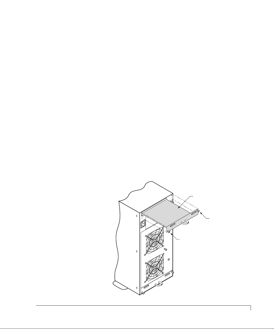
Maintenance
5 Remove the new cooling fan from the shipping carton and inspect the
shipment. Save the packaging material.
6 With the fan guard facing toward the inside of the cabinet, slide the new fan
into its housing.
7 Reconnect the fan’s power cable connector. The connector is keyed and will
install only one direction.
8 Close the rear door panel. The door has a latch mechanism that holds the
door in the open position. Squeeze the latch to release the door allowing it to
be closed.
9 Secure the door with the access panel screw.
10 Using the packaging materials from the replacement po w er supply, repackage
and return it to nStor Corporation, refer to the nStor Resource Guide for
information on “Obtaining a Return Material Authorization.”
Replacing an I/O Interface Card
1 Identify the failed I/O Interface card. Refer to the Troubleshooting chapter
for information on identifying failed cards, “Troubleshooting” on page 53.
2 Turn the power OFF to the CR8e subsystem. The cards are not hot swappable.
I/O Interface Card
Thumb Screw
Thumb Screw
Replacing an I/O Interface Card
61
Page 74
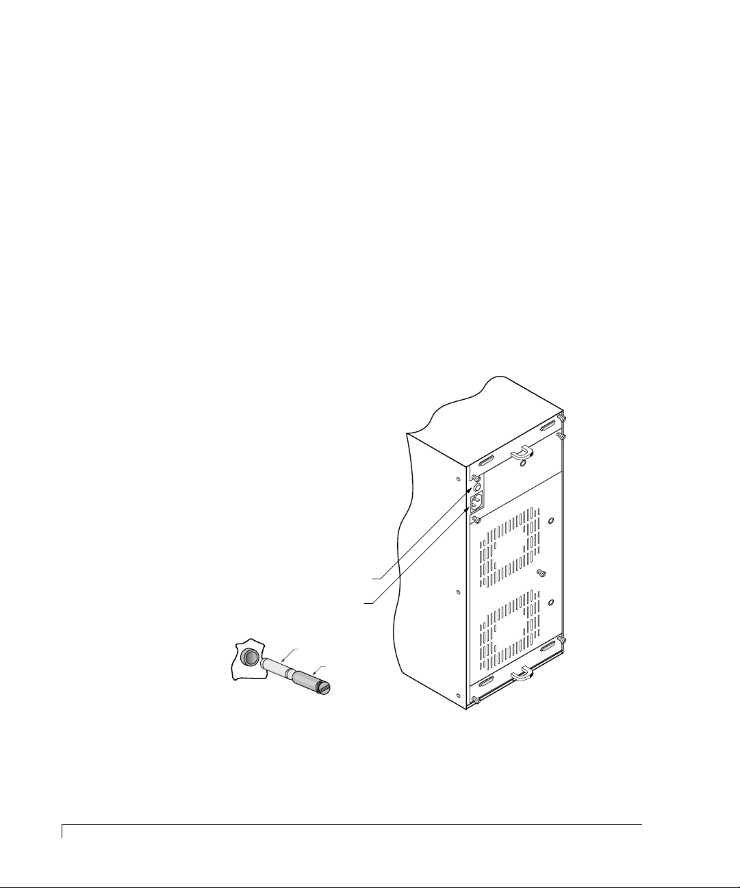
Maintenance
3 Loosen the two thumb screws that secures the card.
4 Insert the new I/O Interface card and tighten the thumb screws. Do not
overtighten the fasteners.
5 Using the packaging materials from the replacement card, repackage the
failed card and return it to nStor Corporation. Refer to the nStor Resource
Guide for information on “Obtaining a Return Material Authorization.”
Replacing a Fuse
CAUTION: Power off the subsystem and disconnect the power cord before
changing the fuse.
1 Locate the fuse holder on the rear panel of the CR8e.
62
Replacing a Fuse
Fuse Assembly
Power Connector Module
Fuse (250V 10A)
250V
Fuse Holder
2 Using a small coin, turn the fuse holder counter-clockwise one quarter turn,
releasing the holder from its locked position.
Page 75

Maintenance
3 Using the tip of your finger nail, ease the holder away from the unit.
4 Once removed, separate the fuse from the holder.
5 Replace the fuse with one of identical type and rating (250V 10A).
6 Insert the fuse into the holder.
7 Insert the fuse holder into the unit and secure it. Push in while turning
clockwise one quarter turn, locking it into place. Do not overtighten.
Replacing the CR8e Cabinet
CAUTION: Drives and printed circuit board components are sensitive to
electrostatic discharge. To prevent operating failure or damage,
observe the following: Establish a ground for yourself by using the
wrist grounding strap, or by touching the metal chassis prior to
handling or installing the drives or printed circuit board components.
1 Remove your new enclosure cabinet from the shipping carton and inspect the
shipment. Save the packaging material.
2 Turn the power OFF to the computer system and the old CR8e enclosure.
NOTE: Note the position of the data cables, disk drives, and the jumpers on I/O
Interface cards prior to disconnecting or removing the items. To facilitate
correct installation, you may want to tag the cables appropriately. The
drives should have a drive label located on the front of each drive unit.
3 Remove each drive noting its position and store them in a safe location.
4 Disconnect the data and power cables from the old subsystem enclosure.
5 (Rack Mount Systems Only) Remove the CR8e subsystem from the rack
cabinet assembly.
6 (Single-Bus Modules Only) Remo ve the Single-Bus configur ation module from
the old enclosure and install it into the new subsystem enclosure.
7 (Rack Mount Systems Only) Install the new CR8e subsystem enclosure into the
rack assembly.
Replacing the CR8e Cabinet
63
Page 76

Maintenance
8 If you have a third power supply installed in the old subsystem, remove it and
install the PSU into the new enclosure.
9 Reconnect and secure the power cord and data cables.
10 Install the drives into the new cabinet enclosure in exactly the same order as
they were in the old subsystem.
11 Power ON the new CR8e subsystem and the host computer system.
12 Verify that all systems are operating normally.
13 Using the packaging materials from the new cabinet, repackage the old cabinet
enclosure and return it to nStor Corpor ation, r efer to the nStor Resource Guide
for information on “Obtaining a Return Material Authorization.”
64
Replacing the CR8e Cabinet
Page 77

A
Glossary
The following terms are used throughout this manual and may be helpful
background information on the technology.
Asynchronous
Operations
Cache Flush Refers to an operation where all un-written blocks in a
Channel Refers to one of the SCSI bus connectors on the
Consistency Check Refers to a process where the integrity of redundant data
Disconnect/Reconnect Disconnect is a function that allows a target SCSI device
Operations that bear no relationship to each other in time
and can overlap. The concept of asynchronous I/O
operations is central to independent access arrays in
throughput-intensive applications.
Write-Back Cache are written to the target disk. This
operation is necessary before powering down the system.
controllers or termination interface cards.
is verified. For example, a consistency check of a mirr ored
drive will make sure that the data on both drives of the
mirrored pair are ex actly the same . F or RAID le vel 3 and 5
redundancy, a consistency check will involve reading all
associated data blocks, computing parity, reading parity,
and verifying that the computed parity matches the read
parity.
(typically a disk drive that received a request to perform a
relatively long I/O operation) to release the SCSI bus so
that the controller can send commands to other devices.
When the operation is complete and the SCSI bus is
needed by the disconnected target again, it is reconnected.
65
Page 78

Glossary
Disk Mirroring Data written to one disk drive is simultaneously written
to another disk drive. If one disk fails, the other disk can
be used to run the system and reconstruct the failed disk.
Disk Spanning Several disks appear as one large disk using this
technology. This virtual disk can then store data across
disks with ease without the user being concerned about
which disk contains what data. The subsystem handles
this for the user.
Disk Striping Data is written across disks rather than on the same drive .
Segment 1 is written to drive 0, segment 2 is written to
drive 1, and so forth until a segment has been written to
the last drive in the chain. The next logical segment is
then written to drive 0, then to drive 1, and so forth until
the write operation is complete.
Duplexing This refers to the use of two controllers to drive a disk
subsystem. Should one of the controllers fail, the other is
still available to provide disk I/O. In addition, depending
how the controller software is written, both controllers
may work together to read and write data simultaneously
to different drives.
Fault-Tolerant When something is fault-tolerant it is resistent to failure.
A RAID 1 mirrored subsystem, for example, is
fault-tolerant because it can still provide disk I/O if one of
the disk drives in a mirrored system fails.
Hot Spare The “Hot Spare” is one of the most important features the
controller provides to achieve automatic, non-stop service
with a high degree of fault tolerance. This rebuild
operation will be carried out by the controller
automatically when a SCSI disk drive fails.
Logical Drive A set of contiguous chunks of a physical disk. Logical
disks are used in array implementations as constituents of
logical volumes or partitions. Logical disks are normally
transparent to the host environment, except when the
array containing them is being configured.
Mapping The conversion between multiple data addressing
schemes, especially conversions between member disk
block addresses of the virtual disks presented to the
operating environment by the array management
software.
Mirroring Refers to the 100% duplication of data on one disk drive
to another disk drive. Each disk will be the mirror image
of the other.
66
Page 79

Glossary
Partition An array virtual disk made up of logical disks rather than
physical ones. Also called logical volume.
Physical Drive A ph ysical arr a y (or driv e) is a collection of ph ysical disks
governed by the RAID management software. A physical
drive appears to the host computer as one or more logical
drives.
RAID (Redundant Array of Independent Disks) An approach to
using multiple low cost drives as a group to improve
performance, yet also pr o vide a degr ee of r edundanc y that
makes data loss remote.
RAID 0 Block “striping” is provided, yielding higher performance
than is possible with individual drives. This level does not
provide any redundancy.
RAID 1 Drives are paired and mirrored. All data is 100%
duplicated on an equivalent drive.
RAID 10 RAID 10 is a combination of RAID levels 0 and 1. The
data is striped across disks as in RAID 0. Each disk has a
mirror disk, as in RAID 1.
RAID 3 Data is striped across several physical drives. For data
redundancy one drive is encoded with rotated XOR
redundancy.
RAID 30 Data striping of two or more RAID 3 arrays. RAID level
30 is a combination of 0 and 3.
RAID 5 Data is striped across several physical drives. For data
redundancy drives are encoded with rotated XOR
redundancy.
RAID 50 RAID level 50 is a combination of RAID level 0 and 5.
AM RAID Controller This refers to the controller card that routes data to
and/or from the CPU. Disk array controllers perform all
RAID algorithms onboard the controller.
Rebuild The regeneration of all data from a failed disk in a RAID
level 1, 3, 5, or 6 array to a replacement disk. A disk
rebuild normally occurs without interruption of
application access to data stored on the array virtual disk.
Rotated XOR
Redundancy
This term (also known as “parity”) refers to a method of
providing complete data redundancy while requiring only
a fraction of the storage capacity for redundancy. In a
system configured under RAID 3 and 5, all data and
parity blocks are divided between the drives in such a wa y
that if any single drive is removed (or fails), the data on it
can be reconstructed using the data on the remaining
drives. (XOR refers to the Boolean “Exclusive-OR”
operator.)
67
Page 80

Glossary
SAF-TE Is the acronym for SCSI Accessed Fault-Tolerant
Enclosures. It is a monitoring and communication
specification developed by Conner (nStor) and Intel for
sending and receiving server and storage system status
information via the SCSI bus.
Session Refers to the period of time between any two consecutive
system shutdowns. System shutdown may be either a
power off/on, or a hardware reset.
SCSI Drive A disk drive equipped with a small computer system
interface (SCSI). Each disk drive will be assigned a SCSI
address (or SCSI ID), which is a number from 0 to 15. The
SCSI address uniquely identifies the drive on the SCSI bus
or channel.
Spanning Disk spanning allows multiple disk drives to function like
one big drive. Spanning overcomes lack of disk space and
simplifies storage management by combining existing
resources or adding relatively inexpensive resources.
Striping Disk striping writes data across multiple disks rather than
on one disk. disk striping involves partitioning each drive
storage space into stripes that can vary in size from one
sector (1 KB) to several megabytes.
Stripe Order The order in which SCSI Drives appear within a Physical
Pack. This order must be maintained, and is critical to the
controller’s ability to “Rebuild” failed drives.
Stripe Width Refers to the number of kilobytes per stripe block.
Target ID A target ID is the SCSI ID of a device attached to the disk
array controller. Each SCSI channel can have up to
sixteen SCSI devices (target ID from 0 to 15) attached to
it.
Write-Through Cache Refers to a cache writing strategy whereby data is written
to the SCSI Drive before a completion status is returned to
the host operating system. This caching strategy is
considered more “secure,” since a power failure will be
less likely to cause loss of data. However, a Write-Through
cache results in a slightly lower performance, in most
environments.
Write-Back Cache Refers to a caching strategy whereby write operations
result in a completion signal being sent to the host
operating system as soon as the cache (not the disk drive)
receives the data to be written. The target SCSI Drive will
receive that data at a more appropriate time, in order to
increase controller performance.
68
Page 81

B
Technical Information
SPECIFICATIONS
CR8e
Operating Environment 40°F to 94°F (+5°C to +34°C)
Relative Humidity
Operating/Non-Operating 5% - 95% (non-condensing)
Power Requirements 100 - 240 VAC (auto-sensing)
50-60 Hz
6.0 Amperes
3 x 150 watts
Rack Mount System
Dimensions (HxWxD) w/o Handles
Tower-Based System
Dimensions (HxWxL)
Weight (basic configuration of cabinet includes
two cooling fans)
Altitude -200 to 10,000 feet
Number of Drives Supported 8
Total Capacity 72.8 gigabytes (9.1 GB Drives)
Interface Transfer Rate Up to 40 MB/sec
Host Interface Fast/Wide SCSI-3
Drive Interface Fast/Wide SCSI-3
HDD Termination Automatic Termination
Electromagnetic Emissions Requirements
(EMI)
6.83" x 17.40" x 19.00"
17.40" x 6.83" x 19.00"
48.0 lbs without drives installed
56.6 lbs with three drives installed
FCC, Part 15, Class B
EN55022-B
69
Page 82
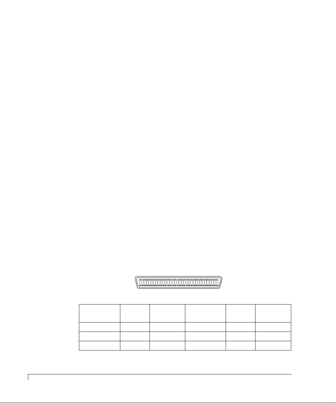
Technical Information
134
35 68
VHD/HD 68-pin SCSI
P-Cable Connector
Pin-out
CONNECTORS AND JUMPERS
This section provides information about the connector pinouts on the
termination interface card and jumper settings on the backplane printed circuit
board for your nStor CR8e subsystem.
Connectors
CR8e (continued)
Safety Requirements UL1950
CSA C22.2 #950
TUV/EN60950
CE Compliance (EMC) 89/336/EEC EMC Directive
Shock
Operating
Non-Operating
Vibration
Operating
Non-Operating
1.0 G, 2 - 50 ms
20.0 G, 2 - 20 ms
5 - 500 Hz, 0.25 G (pk to pk)
5 - 500 Hz, 1.0 G (pk to pk)
70
Connectors and Jumpers
Located on each termination interface card are two VDH SCSI connectors. They
provide the input/output interface from the subsystem bus to the RAID contr oller
or host adapter card.
Signal Name Pin
Number
+DB(12) 1 1 – DB(12) 35 2
+DB(13) 2 3 – DB(13) 36 4
+DB(14) 3 5 – DB(14) 37 6
Conductor
Number
Signal Name Pin
Number
Conductor
Number
Page 83
Technical Information
Signal Name Pin
Number
+DB(15) 4 7 – DB(15) 38 8
+DB(P1) 5 9 – DB(P1) 39 10
+DB(0) 6 11 – DB(0) 40 12
+DB(1) 7 13 – DB(1) 41 14
+DB(2) 8 15 – DB(2) 42 16
+DB(3) 9 17 – DB(3) 43 18
+DB(4) 10 19 – DB(4) 44 20
+DB(5) 11 21 – DB(5) 45 22
+DB(6) 12 23 – DB(6) 46 24
+DB(7) 13 25 – DB(7) 47 26
+DB(P) 14 27 – DB(P) 48 28
GROUND 15 29 GROUND 49 30
DIFFSENS 16 31 GROUND 50 32
TERMPWR 17 33 TERMPWR 51 34
TERMPWR 18 35 TERMPWR 52 36
RESERVED 19 37 RESERVED 53 38
GROUND 20 39 GROUND 54 40
+ATT 21 41 – ATN 55 42
GROUND 22 43 GROUND 56 44
+BSY 23 45 – BSY 57 46
+ACK 24 47 – ACK 58 48
+RST 25 49 – RST 59 50
+MSG 26 51 – MSG 60 52
+SEL 27 53 – SEL 61 54
+C/D 28 55 – C/D 62 56
+REQ 29 57 – REQ 63 58
+I/O 30 59 – I/O 64 60
+DB(8) 31 61 – DB(8) 65 62
+DB(9) 32 63 – DB(9) 66 64
+DB(10) 33 65 – DB(10) 67 66
+DB(11) 34 67 – DB(11) 68 68
Conductor
Number
Signal Name Pin
Number
Conductor
Number
Connectors
71
Page 84
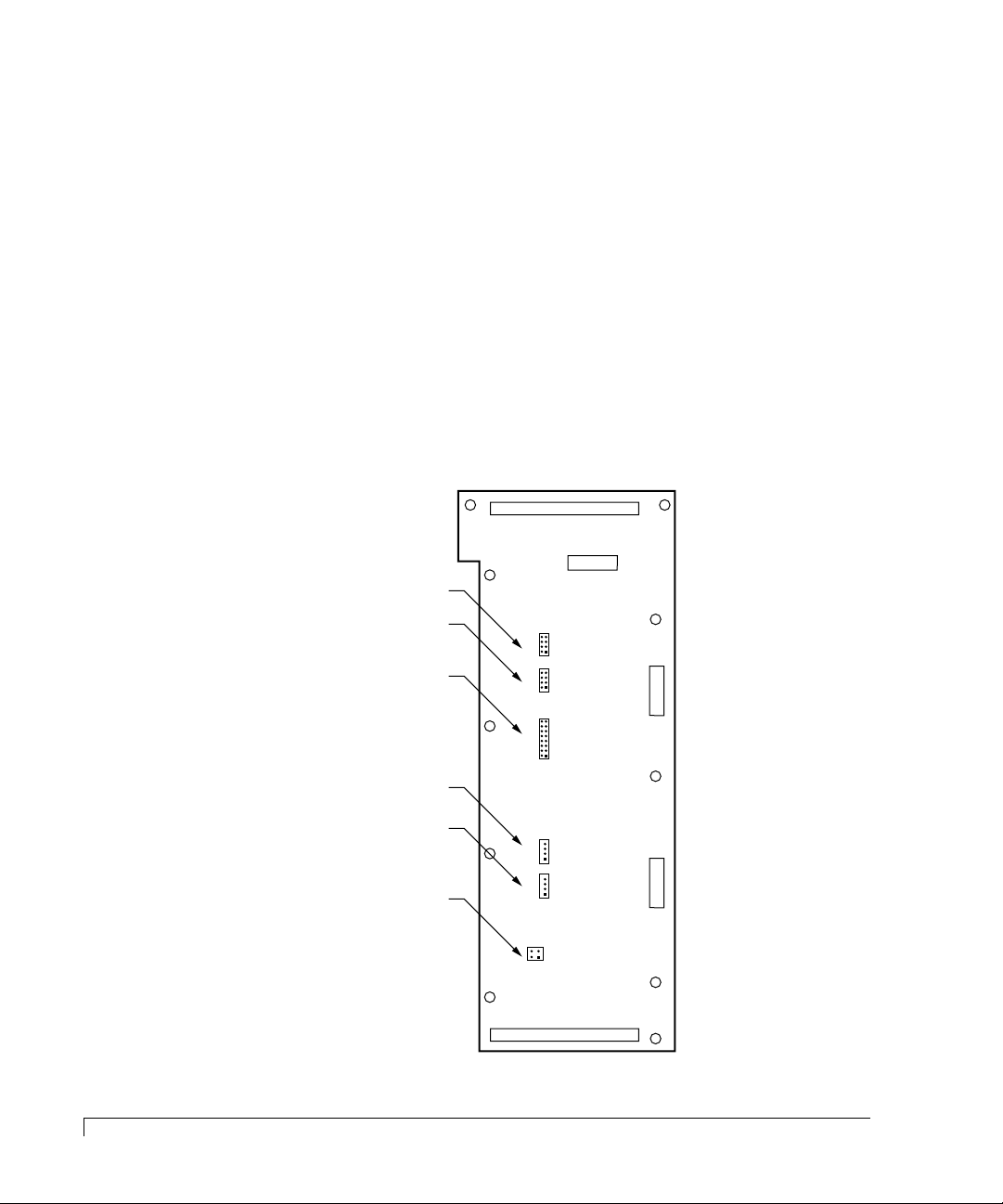
Technical Information
JP3
JP3
JP2
JP2
JP4
JP4
J15
J15
J17
J17
JP5
JP5
1
S2S
SCSI
IDs
S2S
CONFIG
SCSI
IDs
FAN
OEM FAN
REMOTE
DELAY
8
1
1
1
12
1
8
4
4
43
16
Rear View of Backplane PCB
Jumpers
CAUTION: Jumper configuration to be performed by qualified service personnel
Disconnect the AC power cord prior to accessing any component inside the rear
cabinet.
Located on the backplane printed circuit board are six jumper blocks. Fr om these
jumpers system integrators can manually configure the CR8e subsystem. To
change the jumper setting, pull the jumper plug off its pin(s) and carefully fit in
down onto the pin(s) as indicated. This allows the user to make reversible
changes to the circuitry on the printed circuit board.
The jumper settings are knows as “open” or “unjumpered” and “jumpered.”
When unjumpering the setting remove the jumper plug fr om both pins and seat it
over just one of the pins. This allows the jumper plug to be stored for later use.
only.
72
Jumpers
Page 85
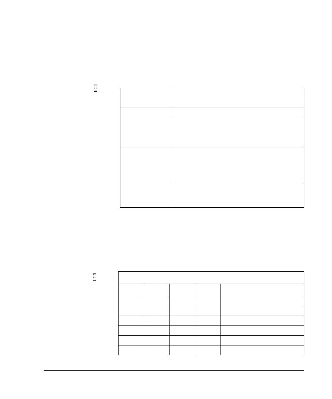
Technical Information
JP2 (SCSI-to-SCSI Configuration)
CAUTION: Jumper configuration to be performed by qualified service personnel only.
This jumper (JP2) is used to place the SCSI-to-SCSI RAID controller in a
configuration that is known to the CR8e subsystem. This process is accomplished
by adding jumpers to JP2. The jumper block is a four position dual-row header.
8
S2S
CONFIG
JP2
1
Jumper
SCSI-to-SCSI Settings
Positions
1 & 2 Reserved.
3 &4 Add this jumper to place the SCSI-to-SCSI controller
into VT100 mode for the serial channel. R emov e the
jumper to place the SCSI-to-SCSI controller into the
SLIP port mode.
5 & 6 Add this jumper to place the SCSI-to-SCSI controller
into the Fixed Baud Rate mode for the serial
channel. Remove the jumper to place the SCSI-toSCSI controller into the Variable Baud Rate mode
for the serial channel.
7 & 8 Add this jumper to place the SCSI-to-SCSI controller
in a Master configuration. Remove the jumper to
place the SCSI-to-SCSI controller in a Slave mode.
JP3 (SCSI-to-SCSI IDs)
CAUTION: Jumper configuration to be performed by qualified service personnel only.
These jumpers (JP3) are used to manually set the SCSI-TO-SCSI IDs for the
SCSI-to-SCSI RAID controller. JP3 is an four position dual-row header.
JP3
S2S
8
SCSI
IDs
1
Jumper Positions
1 & 2 3 & 4 5 & 6 7 & 8 SCSI-to-SCSI ID Settings
ON ON ON ON 15
OFF ON ON ON 14
ON OFF ON ON 13
OFF OFF ON ON 12
ON ON OFF ON 11
OFF ON OFF ON 10
JP2 (SCSI-to-SCSI Configuration)
73
Page 86
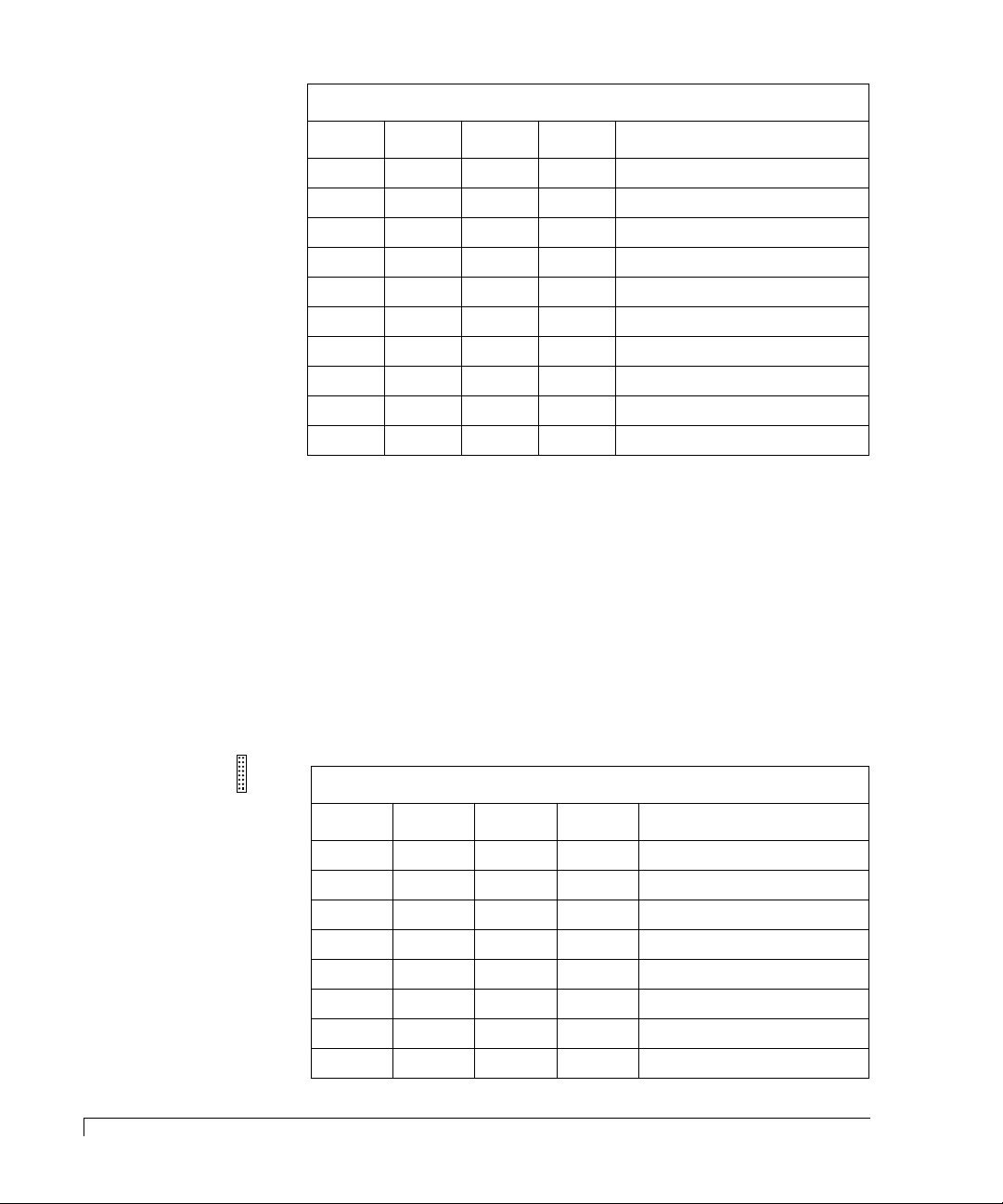
Technical Information
JP4 (SCSI ID Settings)
CAUTION: Jumper configuration must be performed by qualified service personnel
Jumper Positions
1 & 2 3 & 4 5 & 6 7 & 8 SCSI-to-SCSI ID Settings
ON OFF OFF ON 9
OFF OFF OFF ON 8
ON ON ON OFF 7
OFF ON ON OFF 6
ON OFF ON OFF 5
OFF OFF ON OFF 4
ON ON OFF OFF 3
OFF ON OFF OFF 2
ON OFF OFF OFF 1
OFF OFF OFF OFF 0
only .
74
JP4 (SCSI ID Settings)
These jumpers (JP4) are used to manually set the SCSI IDs for all of the disk drive
slots. JP4 is an eight position dual-row header.
The tables for Drives 1, 2, 3, 4, and Drives 5, 6, 7, 8 found on this page and the
following page also provides a list of the possible combinations of SCSI IDs that can
be set when using the Operator Control Panel preset feature for each drive group.
16
SCSI
JP4
IDs
1
Jumper Positions for Drives 1, 2, 3, and 4 ID Settings
1 & 2 3 & 4 5 & 6 7 & 8 SCSI ID (1, 2, 3, and 4)
ON ON ON ON 0, 1, 2, 3
OFF ON ON ON 0, 1, 2, 4
ON OFF ON ON 4, 5, 6, 7
OFF OFF ON ON 4, 5, 6, 8
ON ON OFF ON 5, 6, 7, 8
OFF ON OFF ON 5, 6, 8, 9
ON OFF OFF ON 8, 9, 10, 11
OFF OFF OFF ON 9, 10, 11, 12
Page 87
Technical Information
Jumper Positions for Drives 1, 2, 3, and 4 ID Settings
1 & 2 3 & 4 5 & 6 7 & 8 SCSI ID (1, 2, 3, and 4)
ON ON ON OFF 10, 11, 12, 13
OFF ON ON OFF 10, 11, X, X
Jumper Positions for Drives 5, 6, 7, and 8 ID Settings
9 & 10 11 & 12 13 & 14 15 & 16 SCSI ID (5, 6, 7, and 8)
ON ON ON ON 0, 1, 2, 3
OFF ON ON ON 0, 1, 2, 4
ON OFF ON ON 4, 5, 6, 7
OFF OFF ON ON 4, 5, 6, 8
ON ON OFF ON 5, 6, 7, 8
OFF ON OFF ON 5, 6, 8, 9
ON OFF OFF ON 8, 9, 10, 11
OFF OFF OFF ON 9, 10, 11, 12
ON ON ON OFF 10, 11, 12, 13
OFF ON ON OFF 10, 11, X, X
JP5 (SCA Remote/Delay start)
CAUTION: Jumper configuration to be performed by qualified service personnel only.
The spin-up of the drive slots is determined by adding jumpers to JP5. JP5 is a two
position dual-row header. Position 1 & 2 control the “Delayed_Start” signal and
position 3 & 4 control the “Remote_Start” signal.
43
REMOTE
DELAY
JP5
12
Pins 1 and 2 Pins 3 and 4 Drive Spinup Mode
ON ON Motor spins up only on SCSI
“start” commands.
ON OFF Motor spins up after a delay of 12
(may vary depending on drive
type) seconds times the numeric
SCSI ID setting of the associated
drive.
JP5 (SCA Remote/Delay start)
75
Page 88
Technical Information
J15
J17
FAN
OEM FAN
1
1
4
4
J15 (FAN) and J17 (OEM FAN)
CAUTION: Jumper configuration to be performed by qualified service personnel only.
There are two separate fan connectors that are located at J15 and J17. Fan
connector J15 is used when a SAF-TE card is present in the CR8e. When the fans
are plugged into J15, the SAF-TE card controls and monitors fan speed.
Fan connector J17 is used in OEM applications when there is no SAF-TE card
installed. Fan connector J17 supplies each fan with +12 volts for full speed
operation.
Pins 1 and 2 Pins 3 and 4 Drive Spinup Mode
OFF ON Motor spins up only on SCSI
“start” commands.
OFF OFF Motor spins up at DC power on.
76
J15 (FAN) and J17 (OEM FAN)
Page 89

Index
A
Activity LEDs 10
Animated icon 41
Audible Alarm 3
B
Backplane 72
C
Cables 20
Cabling Configuration 20
Change Passcode 51
Channel Mode LED 9
Component Installation 17
Component Status 43
Components
Activity LEDs 10
Audible Alarm 3
Channel Mode LED 9
Configuration Modules 7
Cooling Fans 4
Door Lock 5
Fan Status LED 10
Fault LEDs 11
Hot Swappable Disk Drives 4
I/O Interface Card 6
Operator Control Panel 8
Power Cord Connector 6
Power Supply Status LED 10
Power Switch 5
Power-On LED 9
SAF-TE 11
SAF-TE Card 11
Configuration Info 43
Connectors and Jumpers 70
Cooling Fan
Replacement 60
Cooling Fans 4
CR8e Cabinet
Replacement 63
D
DC Good LED 59
Dimensions 69
Door Lock 5
Drive Latching Clips 17
Drive Replacement 57
Dual-Bus Module (Single Cabinet) 22, 26
Dual-Bus Module (Two Cabinets) 28
Dual-Bus Module Cabinet with Two Single-Bus
Module Cabinets 34
E
EMC 70
EMI 69
F
Failed Diagnostic Test 54
77
Page 90

Fan Status LED 10
Fast SCSI 20
Dual-Bus Module (Single Cabinet) 26
Dual-Bus Module (Two Cabinets) 28
Dual-Bus Module Cabinet w/Two Single-Bus
Module Cabinets 34
Single-Bus Module (Single Cabinet) 30
Fast Wide SCSI 20
Fast Wide SCSI Mode 26
Fast Wide SCSI mode 20
Fast-20 20
Firmware Error Conditions 38
Firmware information 43
Fuse 6
Replacement 62
Fuse type 63
G
Glossary
Disk Mirroring 66
Disk Spanning 66
Disk Striping 66
Duplexing 66
Fault-Tolerant 66
RAID 67
H
Hardware Error 54
Hardware Menu 42
Heat Threshold 49
Hot Spare 66
Hot Swappable Disk Drives 4
I
I/O Interface Card 6
Installing
Third Power Supply 19
Interface Transfer Rate 69
Internal Temp 45
J
J15 76
JP2 73
JP3 73
JP4 74
JP5 75
Jumpers 72
L
LED
Channel Mode 9
Descriptions 39
Fan Status 10
Power Supply Status 10
LED Descriptions 39
Logical Drive 66
M
Mapping 66
Mirroring 66
N
NVRAM 37
O
OB (Off Bus) 47
Operating Environment 69
Operator Control Panel 8
Options Menu 46
Other Configurations 36
P
Passcode 51
Physical Drive 67
POST 37
POST Results 44
Power Cord Connector 6
Power Requirements 69
Power Supplies 5
Power Supply
Replacement 58
Power Supply Status LED 10
Power Switch 5
Power-On LED 9
Product Registration vii
R
Rack-Mount Subsystem Assembly 15
RAM Checksum Failure 38
RAM Read/Write 38
README vii
Rebuild 67
Register Read/Write Failure 38
78
Index
Page 91

Registration vii
Replacing a Drive 57
Replacing a Fuse 62
Replacing a Power Supply 58
Replacing the Cooling Fans 60
Replacing the CR8e Cabinet 63
Reset Default IDs Selection 48
Resource Guide vii
ROM Checksum 38
S
SAF-TE 68
SAFTE CHAIN ID 50
SCSI Access 37
SCSI Accessed Fault-Tolerant Enclosure 11
SCSI Bus Access Failure 38
SCSI Bus Hangs 55
SCSI cable length
limits 20
SCSI ID Menu 46
Self Test 37
Setup 13
Shielded data cables 21
Shock 70
Single-Bus module 17
Single-Bus Module (Single Cabinet) 30
Single-Bus Module (Two Cabinets) 32
Specifications 69
Startup Screens 40
Status LEDs 10
Stripe Order 68
Stripe Width 68
Striping 68
System Requirements 14
System Status Icon 41
U
Ultra SCSI
Dual-Bus Module (Single Cabinet) 22
Fast 20 20
Single-Bus Module (Single Cabinet) 24
Ultra Wide SCSI Mode 22
Ultra Wide SCSI mode 20
Unlock Options 52
V
VDH SCSI connectors 70
Vibration 70
W
Weight 69
Where to Find Answers vii
T
Technical Information 69
Temperature Threshold Exceeded 54
Termination 21
Testing ROM 37
Third Power Supply 19
Troubleshooting
Fails to Turn On 53
LEDs Not Functioning 56
Index
79
Page 92

80
Index
 Loading...