

Page 1
Micromotor for Laboratory Work
IMPORTANT INSTRUCTIONS AND WARNING - Electric Devices
WARNING !
When using electric tools, basic safety precautions should always be followed to reduce the risk of fire, electrical shock
and personal injury, including the following.
Read all these instructions before operating this product and save these instructions.
A. GROUNDING INSTRUCTIONS
1. In the event of a malfunction or breakdown, grounding provides a path of least resistance for electric current to
reduce the risk of electric shock. This tool is equipped with an electric cord having an equipment-grounding
conductor and a grounding plug. The plug must be plugged into a matching outlet that is properly installed and
grounded in accordance with all local codes and ordinances.
2. Do not modify the plug provided - if it will not fit the outlet, have the proper outlet installed by a qualified electrician.
3. Improper connection of the equipment-grounding conductor can result in a risk of electric shock. The conductor with
insulation having an outer surface that is green with or without yellow stripes is the equipment-grounding conductor.
If repair or replacement of the electric cord or plug is necessary, do not connect the equipment-grounding conductor
to a live terminal.
4. Check with a qualified electrician or service personnel if the grounding instructions are not completely understood,
or if in doubt as to whether the tool is properly grounded.
5. Use only 3-wire extension cords that have 3-prong grounding plugs and 3-pole receptacles that accept the tool's
plug.
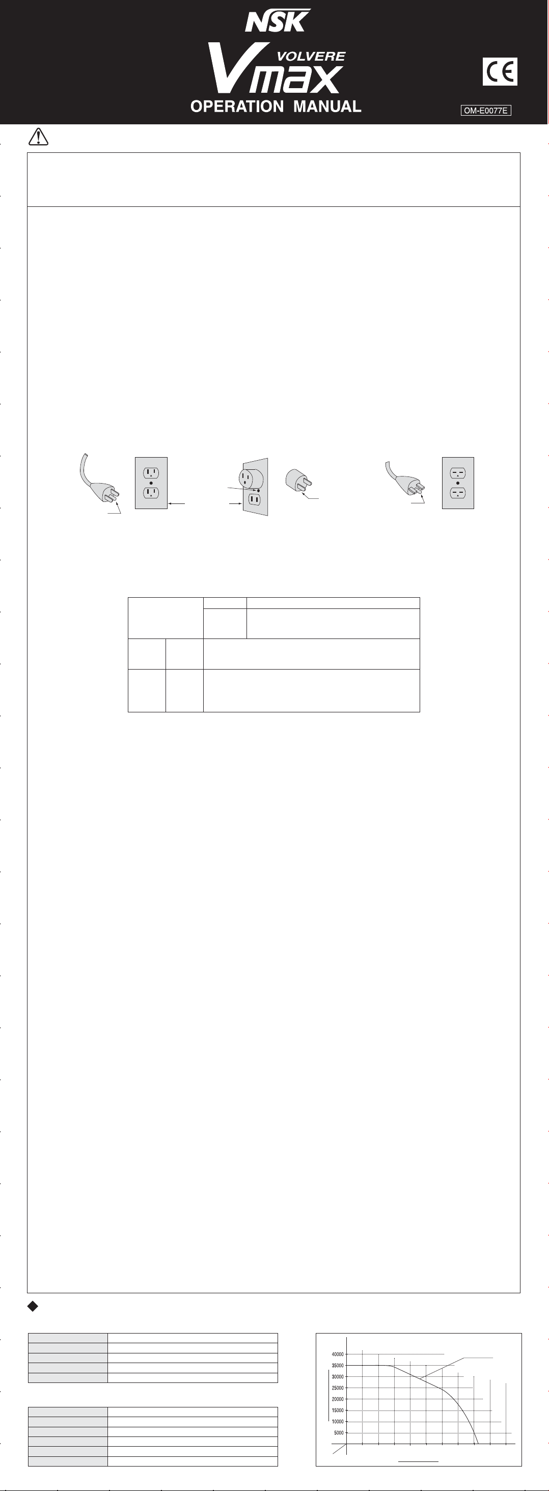
6. This tool is intended for use on a circuit that has an outlet that looks like the one illustrated in Sketch A in Figure
(below)(120V). The tool has a grounding plug that looks like the plug illustrated in Sketch A in Figure (below). A
temporary adapter, which looks like the adapter illustrated in Sketches B and C, may be used to connect this plug to
a 2-pole receptacle as shown in Sketch B if a properly grounded outlet is not available. The temporary adapter
should be used only until a properly grounded outlet can be installed by a qualified electrician. The green-colored
rigid ear, lug, and the like, extending from the adapter must be connected to a permanent ground such as a properly
grounded outlet box.
Grounding Method
002
ADAPTER
GROUNDING
PIN
(A)
METAL SCREW
COVER OF GROUND
OUTLET BOX
(B)
(C)
GROUNDING
MEANS
GROUNDING
PIN
(D)
7. USE PROPER EXTENSION CORD. Make sure your extension cord is in good condition. When using an extension
cord, be sure to use one heavy enough to carry the current your product will draw. An undersized cord will cause a
drop in line voltage resulting in loss of power and overheating. Table (below) shows the correct size to use
depending on cord length and nameplate ampere rating. If in doubt, use the next heavier gauge. The smaller the
gauge number, the heavier the cord.
Minimum gauge for cord
Volts
Ampere Rating
More
Than
0
6
10
12
Not
More
Than
6
10
12
16
120V
240V
7.5m(25ft.)
15m(50ft.)
#18
#18
#16
#14
B. OTHER WARNING INSTRUCTIONS
1. For your own safety read instruction manual before operating tool.
2. Wear eye protection.
3. Replace cracked wheel immediately.
4. Always use guards and eye shields.
5. Do not overtighten wheel nut.
6. Use only flanges furnished with the grinder.
7. REMOVE ADJUSTING KEYS AND WRENCHES. From habit of checking to see that keys and adjusting wrenches
are removed from tool before turning it on.
8. KEEP WORK AREA CLEAN. Cluttered areas and benches invite accidents.
9. DON’T USE IN DANGEROUS ENVIRONMENT. Don’t use power tools in damp or wet locations, or expose them to
rain. Keep work area well lighted.
10. Risk of injury due accidental starting. Do not use in an area where children may be present.
11. DON’T FORCE TOOL. It will do the job better and safer at the rate for which it was designed.
12. USE RIGHT TOOL. Don't force tool or attachment to do a job for which it was not designed.
13.
WEAR PROPER APPAREL. Do not wear loose clothing, gloves, neckties, rings, bracelets, or other jewelry that might
get caught in moving parts. Nonslip footwear is recommended. Wear protective hair covering to contain long hair.
14. ALWAYS USE SAFETY GLASSES. Everyday eyeglasses only have impact resistant lenses, they are NOT safety
glasses. Also use face or dust mask if cutting operation is dusty.
15. SECURE WORK. Use clamps or a vise to hold work when practical. It’s safer than using your hand and it frees both
hands to operate tool.
16. MAINTAIN TOOLS WITH CARE. Keep tools sharp and clean for best performance and to reduce the risk of injury to
persons. Follow instructions for lubricating and changing accessories.
17. DISCONNECT TOOLS before servicing; when changing accessories, such as blades, bits, cutters, and like.
18. REDUCE THE RISK OF UNINTENTIONAL STARTING. Make sure switch is in off position before plugging in.
19. USE RECOMMENDED ACCESSORIES. Consult the owner’s manual for recommended accessories. The use of
improper accessories may cause risk of injury to persons.
20.
NEVER LEAVE TOOL RUNNING UNATTENDED. TURN POWER OFF. Don’t leave tool until it comes to a complete stop.
21. For recommended operating speed for various applications, please follow the instructions of bur manufacturers.
22. Use Accessories suitable for Max. 40,000
min-1(rpm).
23. The system functions normally in the environment where the temperature is at 0-40°C, humidity at 10-85% RH, and
no moisture condensation in the Unit. Use at outside of these limits may cause malfunction.
24. Store the system in the place where the temperature is at -10-60°C, humidity at 10-85% RH, atmospheric pressure
at 500-1060hPa, and the system is not subject to air with dust, sulfur, or salinity.
25. Do not disassemble or alter the product by yourself.
26. Be careful not to be injured by the grinder or bur.
27. Be sure to replace fuse with the correct type and rating.
28. Do not place equipment so that it is difficult to pull cut power supply cord from rear side receptacle.
29. Be sure to turn the power off before cleaning and maintenance of the handpiece.
C. Important Instructions and Warning on VOLVERE Vmax.
1. No lubrication is required to either motor or handpiece because ball bearing filled with grease are used in both
motor and handpiece.
2.
Activation of Circuit Breaker means too much load is applied to the motor beyond the capacity the motor takes. This circuit
breaker is designed to protect the motor, but it is desired to perform the grinding work without activating the circuit breaker.
3. Never move Chuck Control Ring of Lever to the direction of LOOSEN while motor is running.
4. Care should be taken not to drop micromotor handpiece on floor or hard work surface in order to avoid damage
caused by impact shock.
5. While motor is running, care should be taken to prevent foreign particles from entering the motor through the
cooling vent openings.
6. Only use with original power supply cord. In case of damage, contact NSK / Nakanishi service center.
7. Equipment to be sent back to manufacturer for servicing / repair.
Total length of cord
15m(50ft.)
30m(100ft.)
30m(100ft.)
60m(200ft.)
Cord Number
#16
#16
#16
#12
#16
#14
#14
Not Recommended
45m(150ft.)
90m(300ft.)
#14
#12
#12
Specifications
CONTROL UNIT
Model
Power Source
Weight
Dimensions
Output
MOTOR
&
HANDPIECE(STANDARD TYPE
Model
Speed
Maximum Output
Maximum Torque
Weight
Dimensions
NE-120
AC120V/230V 50/60Hz 30W
2kg (4.44Lb)
W95 (3.74") x D190 (7.48") x H180 (7.09")mm
DC35V 0.6A
)
GX35RMS
1,000 - 35,000min
71W (892oz)
4.1cN-m
251g (9.35oz) (include motor cord)
φ24.5 (0.96") x L143.5 (5.65") mm
-1
(rpm)
Torque Characterstics of VOLVERE-Vmax
GX35RMS
(rpm))
-1
Speed (min
0.5 1.0 1.5 2.0 2.5 3.0 3.5 4.0 4.5 5.0
Torque (cN-m)
Page 2
Description
1
2
3
4
5
6
7
8
14
15
9
10
11
12
13
16
20
21
1
Speed Display
2
Motor ON/OFF LED
3
Motor ON/OFF Switch
4
Speed Control Knob
5
HAND LED
6
HAND/FOOT Selector Switch
7
FOOT LED
8
Output Connector
9
Auto Cruise LED
10
Auto Cruise Switch
11
FWD LED
12
FWD/REV Selector Switch
13
REV LED
14
Power Switch
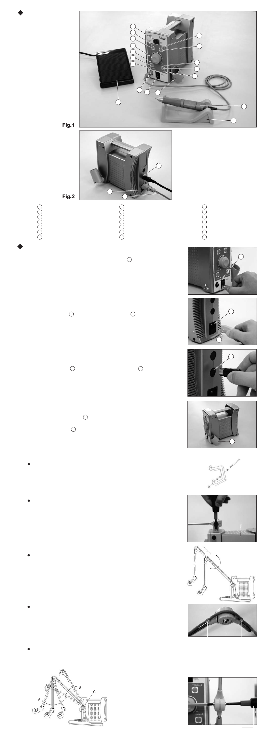
Installation
1. Connecting Motor Cord Plug
Insert the motor cord plug in Output Connector .(Fig.3)
8
19
18
15
Handpiece Holder
16
Foot Control (FC-40)
17
Motor Handpiece
18
Handpiece Stand
19
Foot Control Connector
20
AC Power Fuse Box
21
Power Cord
17
8
2. Connecting Power Cord
Insert Power Cord plug in AC Power Fuse Box
21
20
at the back of the control unit, aligning the fuse box and plug. (Fig. 4)
3. Connecting Foot Control
Insert Foot Control plug in Foot Control Connector
16
19
at the back of the control unit. (Fig. 5)
4. Mounting Handpiece Holder
Mount Handpiece Holder at either side of the control unit.
15
Adjust the angle and tighten the screw. (Fig. 6)
*Handpiece Holder can be mounted at either side of the control unit.
15
Fig. 3
Fig. 4
Fig. 5
20
21
19
Fig. 6
5.
Assembling and Mounting Suspension Handpiece Cradle (Option)
Mount Handpiece Cradle
Mount the handpiece cradle and other parts at the end of the suspension
arm as shown in Fig. 7 and secure with the nut.
Fig. 7
Mounting on Control Unit
Mount the suspension arm on either side of the Control Unit, on which
the handpiece holder is not attached, and secure with the screw. (Fig. 8)
Fig. 8
Adjusting Length of Suspension Arm
Loosen the fastening ring of the suspension arm to extend the arm
and secure with screw. (Fig. 9)
15
Assembling of Hpc. Cradle
Control
Unit
Fastening Ring
Loosen
Tighten
Fig. 9
Setting Motor Cord
Place the motor handpiece on the handpiece cradle on the work bench.
Take enough cord length for work, and lock the motor cord in the cord
clamps on the suspension arm. (Fig. 10)
Fig.10
Adjusting Angles of Suspension Arm
Cord Clamp
Angles of A and B are freely adjustable. (Fig. 11) If adjusting the angles repeatedly,
the joint parts might become loose. Tighten the screws with Phillips screwdriver on both sides. (Fig. 12)
Tighten Joint Section
of Arrow C on Fig.11
Fig.12Fig.11
Philips screwdriver
Page 3

Operation Procedures
(1) Insert Power Cord plug into an outlet.
(2) Make sure that Speed Control Knob is set to the lowest position.
(3) Turn on Power Switch , and check if Speed display shows.
(4) Select either forward or reverse direction by FWD/REV Selector Switch . Every pressing alternates FWD and REV.
(5) Select either hand or foot operation by HAND/FOOT Selector Switch . Every pressing alternates HAND and FOOT.
21
4
14
1
12
6
Operation-1
Manual Operation
After (1)-(4) operations above, go to the following procedures.
(5) Select hand operation by HAND/FOOT Selector Switch . (HAND LED lights.)
(6) To operate Motor Handpiece , press Motor ON/OFF Switch .
(Motor ON/OFF LED lights.)
17
2
(7) Adjust the rotation speed by turning Speed Control Knob .
(8) To stop Motor Handpiece , press Motor ON/OFF Switch .
(Motor ON/OFF LED stops lighting.)
17
2
6
3
4
3
5
Operation-2
Foot Control Operation
After (1)-(4) operations above, go to the following procedures.
(5) Select foot operation by HAND/FOOT Selector Switch . (FOOT LED lights.)
(6) To operate Motor Handpiece , apply pressure to Foot Control .
17
(7) Adjust the maximum speed by turning Speed Control Knob . The rotation speed can be adjusted by foot up to
the maximum speed, that is preset by Speed Control Knob . (Variable operation)
(8) To stop Motor Handpiece , stop applying pressure to Foot Control .
17
*Auto Cruise Mechanism
To operate Motor Handpiece at a constant speed below the maximum speed preset by Speed Control Knob ,
press Auto Cruise Switch when the motor handpiece rotates at the required speed. Auto Cruise LED lights
17
10
and the rotation speed would not change even if the foot Control is released. To cancel auto cruise operation,
press Auto Cruise Switch or Foot Control once again.
10
16
6
16
4
4
7
16
1
2
3
4
5
6
12
14
Fig.13
9
4
Caution
Make sure that the chuck control lever or the bur lock ring is at lock position when starting the motor handpiece.
Protective Circuit
When the control unit is overloaded or the motor is to operate in spite of the chuck control lever or the bur lock ring is
in open position, the protective circuit functions to stop the motor and Speed Display shows error codes.
1
To reset the protective circuit,
・ At manual operation, press Motor ON/OFF Switch .
・ At foot control operation, release Foot Control .
3
16
Error Code
When the motor stops operation, Speed Display shows error codes, which instruct what is problem.
Detection of overcurrent
Detection of overvoltage
Detection of discontinuity in
Speed Control Knob
Detection of discontinuity in
Foot Control
Overheating inside the control unit
Breaking circuit error
EEPROM abnormal
Rotor lock error Faulty PC Board.
16
4
Refer to Troubleshooting for action taken when the error code shows.
1
・ Long-time use at excessive load (Overcurrent).
・ Short-circuited power cord.
・ Handpiece trouble.
・ Short-circuited motor winding.
・ Open collet chuck.
Faulty PC Board.
No signal from Speed Control Knob .
No signal from Foot Control .
Long-time use at excessive load built up heat inside the control unit.
・ Abnormal voltage in the starting or the shut-down circuit.
・ The starting or the shut-down circuit trouble.
Internal memory faulty.
4
16
Replacing AC Power Fuse
There is a fuse in AC Power Fuse Box . Push links at the either side of
the fuse case and remove to check.
If the fuse is blown, replace with a new fuse of same rating.
(AC120V: 3.15AH 125V) (AC230V: T800mAH 250V) (Fig. 14)
Caution
Fuse is burned out when a short circuit occurs or when over-voltage
flows into the primary current source. If the cause is uncertain,
return the product to an authorized NSK's service shop for inspection.
20
Handling Motor and Handpiece
1. Replacing Tool
a.) Ring type handpiece
To unlock the collet chuck and remove the tool, turn the bur lock ring to OPEN
with a click. To tighten the collet chuck and mount the tool, turn the bur lock
ring to LOCK with a click. (Fig. 15)
b.) Lever type handpiece
To unlock the collet chuck and remove the tool, make a quarter turn of
the chuck control lever to OPEN. To tighten the collet chuck and mount
the tool, turn the chuck control lever back to LOCK. (Fig. 16)
Fig.14
LOCK
OPEN
Fig.15
OPEN
LOCK
Fig.16
2. Cleaning and Replacing Collet Chuck
(1) Removal of Chuck
To remove the chuck, open the bur lock ring or the chuck control lever and
turn the chuck counterclockwise with the provided spanner wrench. (Fig. 17)
(2) Cleaning of Chuck
Remove and clean the chuck as frequently as possible in the ultrasonic
cleaner. Clean at least once a week.
Caution
Neglecting to clean the chuck for a long time is very dangerous
because wax, gypsum, etc., accumulate in the chuck and the bur is
caught insecurely, causing runout.
(3) Insertion of Chuck
Thinly apply oil before insertion.
Open the bur lock ring or the chuck control lever, insert the dummy bur or
the bur in use into the chuck, and turn the chuck clockwise by hand until it
stops. Then, lock the bur lock ring or the chuck control lever, and the chuck
could hold the bur securely. (Fig. 18)
3. Connecting and Disconnecting Motor Cord and Motor
To remove the motor cord, loosen the joint nut at the back of the motor.
To connect, align the + marks of the motor and the joint nut. Insert the pins
completely and tighten the joint nut. (Fig. 19)
*If connecting inversely, the motor will run in the reverse direction.
Loosen
Fig.17
Turn until snug
Fig.18
molded + markings molded + markings
Joint Nut
Fig.19
Page 4

4. Replacing Carbon Brush
To replace carbon brushes, refer to “Replacing Carbon Brush” of the
operation manual in the package of new carbon brush.
*Carbon Brush for GX35RM/GX35EM (Pack of 2) : Order No. E023-011S
Transmission Clutch
Cautions in connecting the handpiece and the motor
If the drive shaft of the motor does not engage the drive dog on
the handpiece,do not force them to turn. It would break the motor.
Turn the handpiece back a few threads, rotate the collet chuck or
the tool by hand to engage the drive shaft and the drive dog.
Screw them together firmly.
Handpiece Stand
The service tool and the collet chuck can be mounted on the bottom of
the handpiece stand.(Fig. 21)
Troubleshooting
Check followings before requesting repair.
Power Cord is disconnected.
LED Speed Display does not show.
Foot Control does not turn on motor.
Error code E0 shows.
Error code E1 shows.
Error code E2 shows.
Error code E3 shows.
Blown fuse.
Faulty Power Switch.
Foot Control is loose or disconnected.
HAND/FOOT Selector Switch is set to HAND.
The chuck control lever or the bur lock ring is in open position.
Check if the tool can be rotated with fingers.
If you have another motor and motor cord, use them and
check the operation.
Motor rotates at high speed.
Motor does not rotate.
Set HAND/FOOT Selector Switch to HAND
and check the operation.
Handpiece Motor
Fig.20
Fig.21
Insert Power Cord Securely.
Replace a fuse of same rating. If the cause of blown fuse
is unknown, ask for inspection.
Ask for repair.
Connect Foot Control cord securely.
Set to FOOT.
Lock the chuck control lever or the bur lock ring.
If any abnormalities are found during rotation, ask for motor
& handpiece repair.
If replaced motor operates normally, original motor and
motor cord are faulty. Ask for repair.
Ask for control unit repair.
Ask for control unit repair.
Speed Control Knob or PC Board might be faulty.
Ask for control unit repair.
Speed Control Knob or PC Board might be faulty.
Ask for control unit repair.
Action TakenTrouble Probable Cause
Error code E6 shows.
Error code E7 shows.
Error code E8 shows.
Error code E9 shows.
The speed cannot be increased.
Stop operation for approximately 10 minutes in a cool place
and check the operation again.
Repeat starting and stop by Power Switch.
Repeat starting and stop by Power Switch.
Check if the tool can be rotated with fingers.
The max speed can be set with Speed Control Knob
in Foot Control operation mode.
There is no problem if it operates normally. Make sure that
it is not hot in the surroundings and storage location.
If the error code frequently shows, ask for control unit repair.
There is no problem if it operates normally. If the error code
still shows, ask for control unit repair.
If the error code still shows, ask for control unit repair.
If the tool does not rotate normally, ask for motor
and handpiece repair.
Set Speed Control Knob to the max speed.
Problem Cause Action Taken
No rotation when the chuck control lever
or the bur lock ring is locked.
Overheating during rotation.
Vibration and/or noise during rotation.
Heavy tool run-out.
Tool walks out.
Foreign objects inside the ball bearings, or bearings frozen. Ask for repair.
Foreign objects inside the ball bearings
could have worn ball bearings.
Worn ball bearings caused by the foreign objects.
Bent tools. Replace tool.
Debris inside the collet chuck or inside the spindle. Clean inside the collet chuck or the spindle.
Worn collet chuck.
Worn ball bearings. Ask for repair.
Loose collet chuck.
Ask for repair.
Ask for repair.
Replace collet chuck.
Tighten collet chuck securely. (See Handling Motor and Handpiece.)
Optional Micromotor Handpieces series and spare parts
E205
E053
E054
H214
H063
H068
H178
H156
GX35RM & SCD
For Ring Type Handpiece Standard Motor with Straight Motor Cord
GX35M & SCD
For Lever Type Handpiece Standard Motor with Straight Motor Cord
GX35EM & SCD
E-Type Motor with Straight Motor Cord
UHR-35
Ring Type Handpiece for GX35RM
VH
Lever Type Handpiece for GX35M
VH-E
E-Type Lever Type Handpiece for GX35EM
VR-E
E-Type Ring Type Handpiece for GX35EM
VC45
Angle Type Handpiece for GX35M
Model / DescriptionCat.#Product
E257-012
E257-013
Z246
Carbon BrushE023-011S
CHH2.35 φ2.35 chuck H203-180
GX35SCD
Straight Motor Cord
GX35CCD
Coiled Motor Cord
Vmax Handpiece Cradle
Specifications are subject to change without notice. 2014.10.20 005
M
 Loading...