

Page 1
Multi Function Ultrasonic Scaler
OPERATION MANUAL
Please read this Operation Manual carefully before use,
and file for future reference.
Varios 970
OM-E0847E 000
Page 2
Classifications of equipment
• Type of protection against electric shock:
– Class I equipment
• Degree of protection against electric shock:
– Type BF applied part:
• Method of sterilization or disinfection recommended by the manufacture:
– See 12. Sterilization
• Degree of protection against ingress of water as detailed in the current edition of IEC 60529:
– Foot Control: IPX1 (Protected against vertically falling water drops)
• Degree of safety of application in the presence of a flammable anesthetic mixture with air or with oxygen or nitrous oxide:
– EQUIPMENT not suitable for use in the presence of a flammable anesthetic mixture with air or with oxygen or nitrous
oxide.
• Mode of operation:
– Continuous operation
English
Intended to Use
This product is designed only for dental clinic /dental office use. This device generates ultrasonic waves intended for use in
dental applications such as scaling, root canal treatment, periodontal and cavity preparation.
1. Cautions for handling and operation
Read these cautions carefully and use only as intended or instructed.
Safety instructions are intended to avoid potential hazards that could result in personal injury or damage to the device.
Safety instructions are classified as follows in accordance with the seriousness of the risk.
Class Degree of Risk
WARNING
CAUTION
NOTICE
A hazard that could result in bodily injury or damage to the device if the safety instructions are not
followed.
A hazard that could result in light or moderate bodily injury or damage to the device if the safety
instructions are not followed.
General information needed to operate the device safely.
WARNING
• TO PREVENT ELECTRIC SHOCK Do not unplug the power cord with wet hands.
• TO PREVENT ELECTRIC SHOCK Be sure to prevent water on the Control Unit.
• TO PREVENT ELECTRIC SHOCK Do not touch the handpiece backend electrical connections.
• TO PREVENT ELECTRIC SHOCK Use an electrical outlet that is grounded.
• If you feel any abnormality such as vibration, heat generation, abnormal noise, etc., prior or during the use of the unit, stop
using it immediately.
• Do not turn the Power Switch without reason; it might blow out a fuse.
• This product is Medical Electrical equipment Electromagetic compatable (EMC).As described in the accompanying
documentation.
• Portable and mobile RF communications equipment can affect Electrical Medical equipment. Do not use RF equipment in
close proximity to the product.
• When installing the product, provide space of approximately 10cm around the Control Unit for easy access to the inlet and
the Power Cord.
• When operating the product always consider the safety of the patient.
• Use by medical professional, such as doctor or dental hygienist, is intended.
• Check the vibration outside the patient’s oral cavity before use. If any abnormalities are found, stop using immediately and
contact your dealer.
• Do not drop, hit, or subject to excessive shock to the Control Unit/Handpiece.
1
Page 3
• USE ONLY NSK genuine tips when using NSK Varios Ultrasonic Scaler (Varios 970 or Varios 970 LUX) problems such as
damage, failure and accident of Handpieces resulting from use of Non-NSK Tips are not included in the warranty. The
following are the possible failure that could happen when using the Non-NSK Tips;
· Vibration failure caused by using non conforming screws.
· Patients accidental ingestion of broken tips.
· Damage of thread ridge of handpiece.
· You must use the tip within the power range described on the Tip-Power Guide. If you use it out of the power
range, the tip might break or damage an operative site.
• To prevent possible tooth plane damage and handpiece overheating, Always use with sufficient water.
• Do not sterilize by ultraviolet light. Handpiece could discolor.
• Sterilize the Tip, Handpiece, and Tip Wrench by autoclaving. Wipe the Control Unit, AC Power Cord, Foot Control, and
Handpiece Cord including the cover.
• If chemical, solvent or antiseptic solution is deposited on this product, immediately wipe it away. Discoloration or
deformation may occur if left.
• Do not disassemble or alter the handpiece/Control Unit.
• Keep away from patients with cardiac pacemakers.
• Keep away from explosive substances and flammable materials. Do not use for patients anesthetized under laughter gas.
(Nitrous Oxide)
• Use the Fuse of specified rating. (120V: T630mAL 250V, 230V: T315mAL 250V)
• This product needs special precautions regarding EMC and needs to be installed and put into service according to the
EMC information.
• The use of ACCESSORIES, transducers and cables other than those specified, with the exception of transducers and
cables sold by the manufacturer of this product as replacement parts for internal components, may result in increased
EMISSIONS or decreased IMMUNITY of this product.
• This product should not be used adjacent to or stacked with other equipment and that if adjacent or stacked use is
necessary, this product should be observed to verify normal operation in the configuration in which it will be used.
• If any water drops remain on the handpiece after autoclaving, wipe them
off., Staining may result if left.
• There is the judgment that applies this product to a patient in the user side.
• Grounding reliability can only be achieved when the equipment is
connected to an equipment receptacle marked "Hospital Only" or "Hospital
Grade".
• Do not apply excessive power to the Tip. It may damage the teeth because
of the ultrasonic vibration.
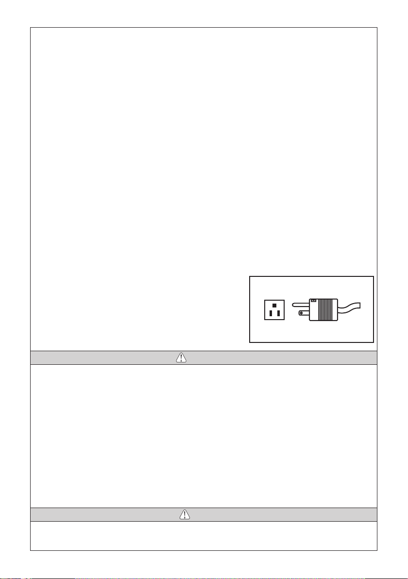
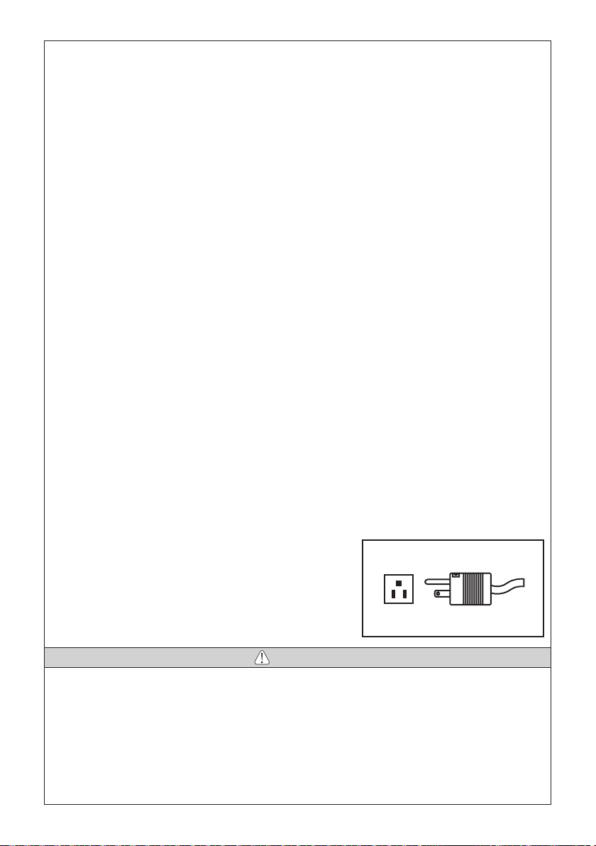
Power plug below is used in N orth America area.
Plug Type NEMA 5-15P (Hospital Grade Type)
CAUTION
• During operation, high frequency oscillations in the handpiece and handpiece cord may affect computer and LAN Noise
may be heard during operation near a radio receiver.
• Be sure to turn off the Power Switch after use. Remove the power plug and water inside of the Control Unit before storage.
• Users are responsible for operational control, maintenance and inspection.
• Clean/sterilize the product immediately after using it. Then store it. Leaving it non-sterile might lead to failure.
• When cleaning, use MinutenWipes (ALPRO) to wipe the surface of the handpiece. Use of chemicals other than those may
cause the handpiece to discolor, crack, etc.
• When you have not used the product for long time and use it again, check the operation before use.
• Eye damage may result if the LED is stared directly into, Do not look into or turn it to the eyes of the patient.
• This product does not consider patient’s age (except infants), gender, weight or nationality.
• No special training is required for this device.
• Applied parts for patient and/or operator are/is tip and Handpiece.
• Surface temperature of tip shall be more than 50 degree without using a tap water or bottle. To avoid this event, be sure
to use a tap water or bottle.
NOTICE
• Repeated autoclaving may cause the handpiece to become discolored due to heat. However, this is due to properties of
the product and is not a problem in terms of quality.
2
Page 4
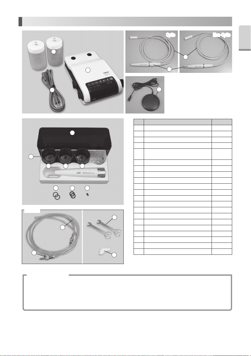
2. Component Names
2
Optic Non-OpticNon-OpticOptic
English
English
5
8
Option
15
3
7
12 13 14
16
1
4
6
No. Parts Name Quantity
1 Control Unit 1
2 VA Bottle 2
3 AC Power Cord 1
4 Varios2 Handpiece (Optic or Non-Optic) 1
Handpiece Cord (Unshielded 2M)
5
119 10
17
18
6 Foot Control 1
7 Sterilization Case 1
8 Tip Wrench 3
9 Tip G4 1
10 Tip G8 1
11 Tip G16 1
12 O-Ring (Thin section) (For VA Bottle) 2
13 O-Ring (Thick section) (For VA Bottle) 2
14 O-Ring (For Handpiece Cord) 2
15 Water Connector (Option) 1
16 Water Tube (Option) 1
17 Spanner Wrench (5x8) (Option) 2
18 Tip Cover S (Option) 1
19 Tip-Power Guide 1*
20 Tip Card 1*
21 Operation Manual 1*
* These are not on photo above.
(Optic or Non-Optic)
1
* Operation Principle
A sinusoidal electrical signal, at ultrasonic frequency ( f > 20Khz ), is delivered by the generator. This signal is applied
to the ‘piezoelectric ceramic’ located inside the transducer. Piezoelectric ceramic converts this signal into mechanical
vibrations. These vibrations are at the same ultrasonic frequency as the electrical signal. The mechanical vibrations
are propagated towards the distal end of the transducer. The “TIP” insert, which is attached at the distal end of the
transducer, vibrates at ultrasonic frequencies and makes it possible to achieve the aimed purpose.
3
Page 5
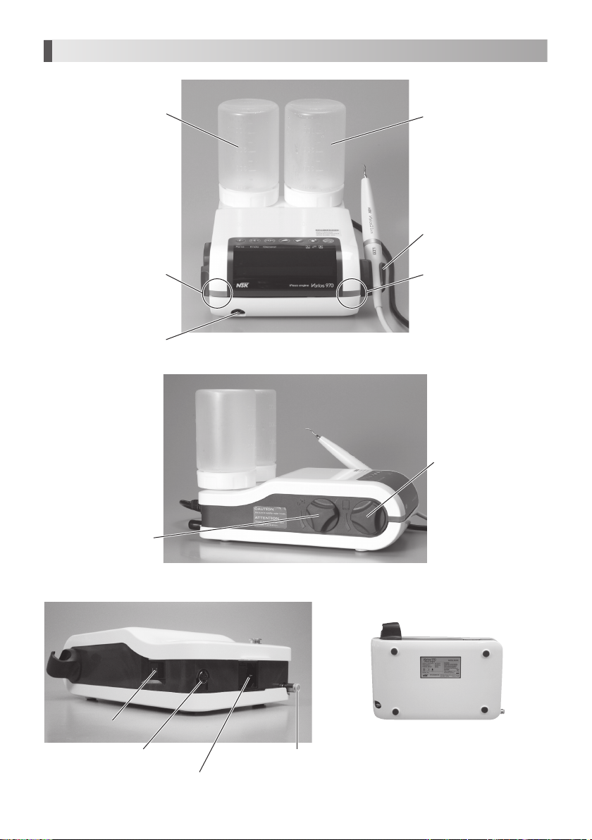
3. Name and Function of each part
Left Bottle (L Bottle) Right Bottle (R Bottle)
* L and R bottle is common
Handpiece Holder
Bottle Selection Indicator L
Handpiece Cord Connector
Tap Water Adjustment Knob
(Left)
Bottle Selection Indicator R
(Right)
Bottle Water Adjustment Knob
Power Switch
Foot Control Connector Tap Water Connector
AC Power Cord Connection Jack
<Bottom>
4
Page 6
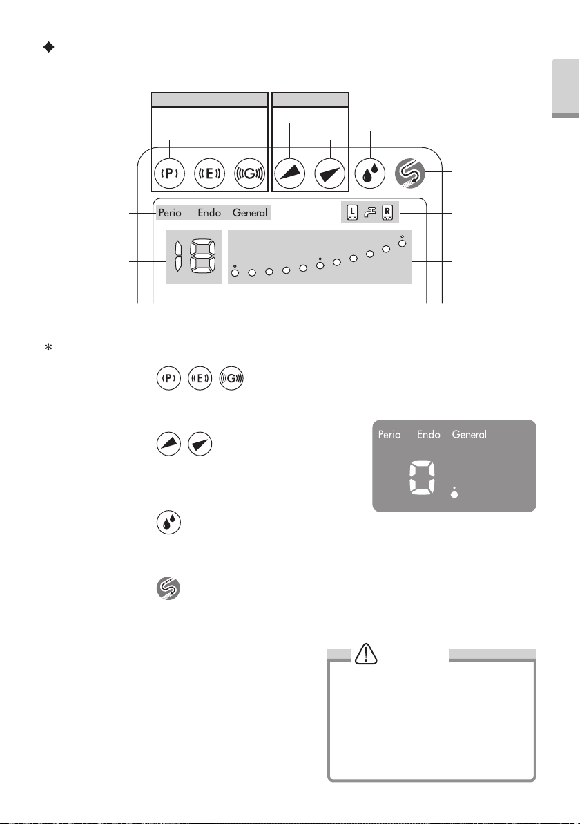
Operation Panel and Display
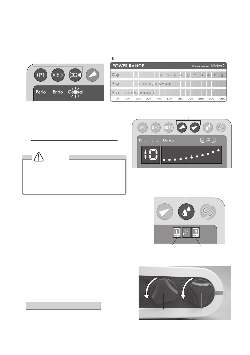
Mode Select Keys Power Level Keys
Endo Key
Perio Key General Key
Down Key
Up Key
Irrigation Select Key
Auto-cleaning Key
English
English
Operation Mode
Display
Numerical Display Bar Graph Indicator
If you purchase the Optional products such as Water Tube and Water Connector you can use Tap Water.
Irrigation Mode
Display
Mode Select Keys
You can select Operation Mode to pressing this key. (Perio, Endo and General) The Control Unit can resume power level,
water volume and irrigation mode for each Operation Mode.
Power Level Keys
Press key to select Power o/p Level . There are 11 levels (0 to 10). There
is no output vibration at level 0 (zero). (Fig.1). The Bar Graph Indicator and
Numerical Display will change simultaneously.
Irrigation Select Key
Press key to select ‘R’ or ‘L’ Bottle. Front panel display and Bottle Selection Indicator simultaneously change in position.
Pressing the Irrigation Select Key for more than one second will select Tap Water Mode.
Auto-Cleaning Key
Press key to select Auto Cleaning Mode, For detail refer to 11. (5).
Fig.1
Bottle Water Adjustment Knob
Water Volume Adjustment can be made prior to the tip vibrating
you can adjust the Water Volume during Bottle Irrigation or
during a wait before Tip vibration start. If the setting is not
applicable (too low or too high) for the Control Unit, it may beep.
During the operation, Front Panel displays the current Power
Level. However, keep turning the knob more than a second; it
may change the Water Volume.
CAUTION
• Do not turn the knob fast. It may not sense
the movement if it turn fast.
• Water Volume can set during 5ml/min to
45ml/min.
• Operation sound may different between
Right and Left Bottle.
• During adjustment of water volume,
Numerical Display indicate “–”.
5
Page 7
Tap Water Adjustment Knob
You can adjust tap water volume by this Knob. (Even the tip vibration).
4. Prior to Operating System
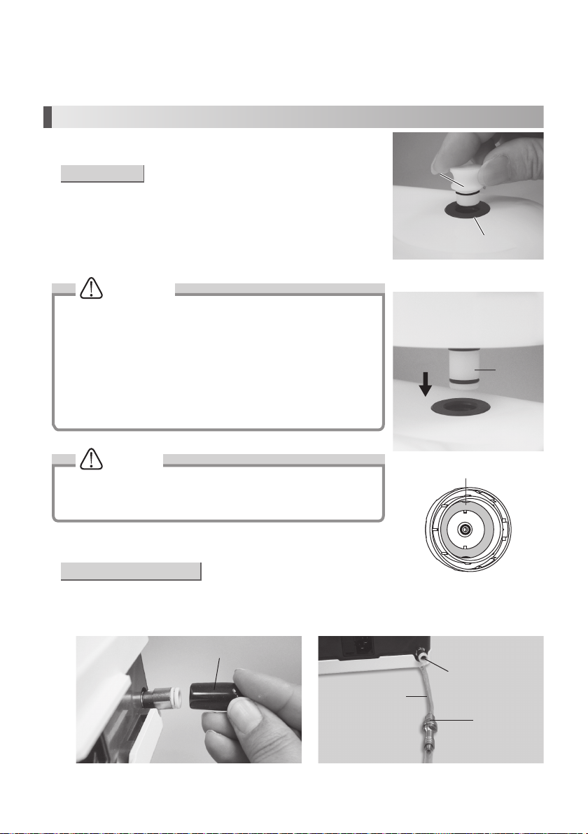
(1) Water System Setup
• Use of Bottle
1) Remove the Dust Cover from the Bottle Base Connector. (Fig. 2)
2) Remove the cap of the VA Bottle and fill solution to the desired level.
3) Close the cap of VA Bottle and insert the Bottle Joint into the Bottle Base
Connector until it clicks. (Fig. 3)
To remove the Bottle, pull it up.
CAUTION
• Use the VA Bottle Set 400 only for Varios 970.
• Before filling solution to the VA Bottle, check the Gasket inside the bottle
cap is clean. (Fig. 4)
• Do not use a sharp tool to clean the Gasket or do not allow any impact
on to the product. It may cause malfunction.
• Insert the Bottle straight. (Damage to seals may result).
• Keep the Gasket clean. When it becomes dirty by water or antiseptic
solution, wash by clean water it immediately.
• The Gasket is consumable. *Optional Gasket: Order Code Z1047350
Dust Cover
Bottle Base Connector
Fig.2
Bottle Joint
NOTICE
• The Bottle calibrations are printed on both sides of the Bottle and can be
read accurately from the fill position or mounted on the Control Unit.
• Mount the Dust Cover when not in use.
• Use of Tap Water (Option)
1) Remove the Cover from the Tap Water Connector. (Fig. 5)
2) Connect the filter side of the Water Tube deep into the Control Unit Tap Water Connector (Fig. 6).
3) Connect the water tube to the water outlet on the Dental Unit.
Cover
Water Tube
Fig.5
6
Gasket
Fig.3
Fig.4
Tap Water Connector
Water Filter Case
Fig.6
Page 8
CAUTION
Ensure the water from the dental unit runs clear before connecting to the scalar.
English
NOTICE
• Insert the Water Tube firmly into Control Unit.
•
Pushing the White Ring, (the Quick Connector Release Ring) on
the Tap Water Connector, gently pull the tube to remove. (Fig. 7)
• When the water tube is not connected, mount the cover on the
Tap Water Connector.
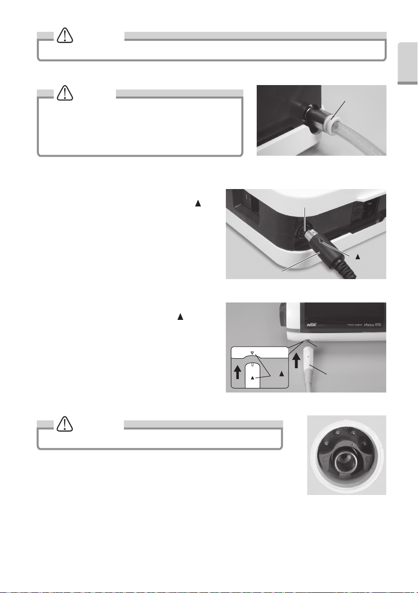
(2) Foot Control Connection
Connect Foot Control Plug and the Control Unit with [ ]
mark on the upper surface of the plug. (Fig.8)
(3) Handpiece Cord Connection
Insert Handpiece Cord Plug into Control Unit. [ ] Mark side
is upper surface. Do not insert it up-side-down. (Fig.9)
Foot Control Plug
Foot Control Connector
Handpiece Cord Connector
[ ]
Mark
White Ring
Fig.7
[ ] Mark
Fig.8
Handpiece Cord Plug
CAUTION
Check that the Handpiece Cord Plug is clean & dry before connecting. (Fig.10)
7
Fig.9
Fig.10
Page 9
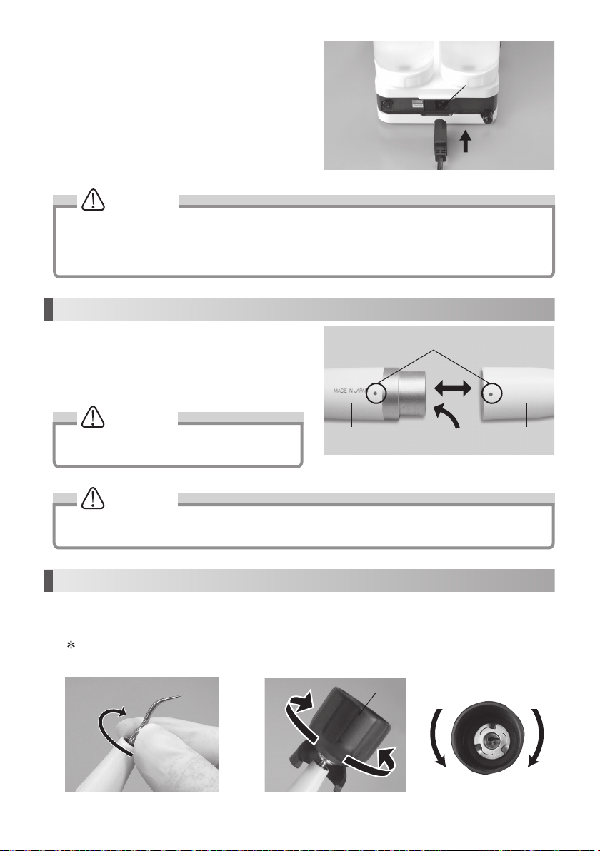
(4) Mounting Power Cord
Insert the Power Cord into the AC Power Cord Connection
Jack at the back of the Control Unit. (Fig. 11)
Power Cord
AC Power Cord Connection Jack
CAUTION
• Ensure Power is OFF on the Control Unit during the Power Cord Connection. It may cause Fuse to blow.
• Do not connect the cord in wall outlet before connecting AC Power Cord.
• Do not pull the AC Power Cord forcibly.
• Do not unplug the Power Cord or handpiece cord while pressing on the Foot Control.
5. Mounting and Removing the Handpiece
Align the Dots on the Handpiece and the Handpiece Cord. Push
handpiece into connector.
To remove the handpiece, grip the Handpiece and Handpiece
Cord and pull to part handpiece and cord. (Fig. 12)
Dots
WARNING
To avoid Electrical Shock Do not touch the handpiece
backend electrical contacts.
Handpiece backendHandpiece Handpiece Cord
Fig.11
Fig.12
CAUTION
• Always confirm that the handpiece is correctly seated and locked into place.
• Do not connect or use Handpiece other than included one (Varios2 handpiece).
6. Mounting and Removing Tip
1) Turn Tip lightly by hand, and install it. (Fig. 13)
2) Tip will insert from the bottom hole of Tip Wrench. Align the four corner of the Tip base area into the four corner of Tip
Wrench. And turn it clockwise until it clicks. (Fig. 14)
Do not touch the top part of Tip to avoid an injury. (There is the case that is longer than height of TIP WRENCH)
To remove the Tip, turn it counterclockwise with the Tip Wrench.
Fig.13
Tip Wrench
Loosen
Tighten
Loosen
8
Tighten
Fig.14
Page 10
Caution for Tip Usage
• Check the Tip before use. (Flush, Damage, Bending or Rust)
• Do not exceed Maximum Power Level for Tip. Damage to tooth structure and Tip may result.
• Do not hit ceramic prosthesis with Tip during scaling. Tip Damage may result.
• Do not hit metal or prosthetic crown except for removing them. Tip could break and fall into mouth.
• Do not hit gingival, mucosa and/or skin. It could cause damage and/or burn injury.
• Do not sharpen and/or bend the Tip. Tip may damage and not generate enough vibration during scaling.
• During cutting, Tip will gradually wear away, as the Tip wears the stroke will get smaller and decrease cutting
efficiancy When level drops too far, change the Tip.(tip card check)
• DO ENSURE When securing tip to use the tip wrench as supplied, inefficient cutting will result.
• DO ENSURE before attaching Tip, Cleanliness of the tip screw, inefficient cutting will result.
• To avid personal injury DO ENSURE tip is removed prior to disconnecting the handpiece or the handpiece cord.
• If you feel the Tip is not vibrating, remove it from an operative site, and press the Foot Control again. If this does
not improve the condition, Ensure the tip is secure, turn the power off and restart it.
• When mounting the Tip, always use groves and Tip Wrench as supplied.
• Ensure that water volume must be “0”, when you use Tip which does not appear of water.
• Tip Wrench is consumable For reliable operation replace annually.
7. Operating Procedures
(1) Water System Setup
• Use of Bottle
1) Check that the VA Bottle is filled to the proper level.
2) Make sure that the cap of the Bottle is secure and not leaking.
CAUTION
• DO ENSURE liquid temperature is below 35°C.
• Do not put liquid such as high acid water in the Bottle.
English
• Use of Tap Water
1) Ensure water tube is firmly connected.
2) Open the dental unit's water valve. (Set water pressure between 0.1-0.5MPa (1-5 kgf/cm
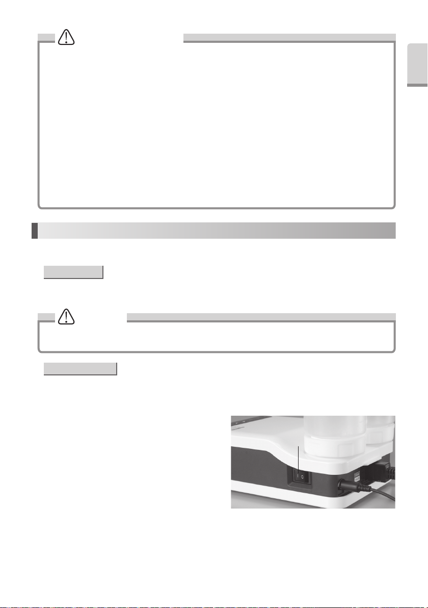
(2) Power On
Connect the AC Power Cord to the wall outlet. Turn the Power
Switch on the Control Unit. Front Display will illuminate.
9
Power Switch
2
)).
Fig.15
Page 11
(3) Power Level Setting
DO ENSURE Power setting does not exceed the recommended Power Level (Tip-Power Guide included in the package.)
1) Select the Operating Mode with the Mode Select Keys on the Front Panel. The Indicator light over the selected mode
will illuminate. (Fig. 16)
Mode Select Keys
Power Level for each mode
Operating Mode Display
2) Set the power level with the Power Level Key on the
Front Panel. The Bar Graph Indicator and Numerical
Display will indicate the selected power level. (Fig. 17)
Make sure the power level is set in the appropriate
range for the attached Tip.
Fig.16
NOTICE
• Press & Hold the Power Level Key will increase or
decrease the Power Level.
• If the Power Level is 0 (zero) and set the water
volume, Tip will not oscillate but water comes out
from the handpiece.
(4) Irrigation setting
Select the Irrigation Mode (L Bottle, R Bottle or Tap Water) with
the Irrigation Select Key on the Front Panel. (Fig. 18)
The Indicator light over the selected mode will illuminate.
Press & Hold the Irrigation Select Key to select Tap Water Mode.
(5) Operate Varios 970 / 970 LUX
By stepping on the Foot Control, the tip vibrates and spraying
starts (except for tips that do not spray) and the handpiece
LED lamp lights up (Varios 970 LUX).
When you remove your foot from the foot control, tip vibration
and water spraying stop and the handpiece LED lamp turns
off. (Varios 970 LUX).
Power Level Key
Bar Graph IndicatorNumerical Display
Irrigation Select Key
L Bottle Tap Water R Bottle
Increase
Fig.17
Fig.18
Increase
• Water Supply Volume Adjustment
Turn the Water Adjustment Knob counterclockwise gradually
to increase the supply volume. (Fig. 19) For detail, refer to P5
Bottle Water Adjustment Knob or P6 Tap Water Adjustment
Knob.
10
Tap Water Adjustment Knob Bottle Water Adjustment Knob
Fig.19
Page 12
CAUTION
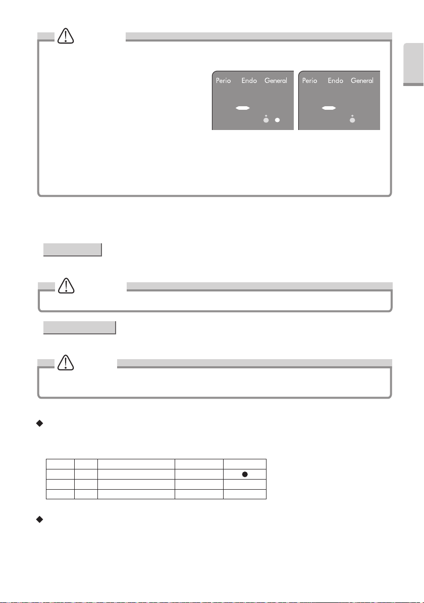
• While pressing the Foot Control and switching the power ‘ON’. The Control Unit will display "F" and sound a beep,
for your safety the Control Unit will not operate. Remove your foot from Foot Control to cancel and reset.
• Bar Graph Display (Fig.20)
Minimum Irrigation -> One white and blue LED.
No Irrigation -> Blue LED only
• Always use the water supply. If water supply is
insufficient, handpiece will overheat and patient’s
tooth surface can be injured.
• Verify that the water spray is clean and of
adequate volume before use.
• If irrigation volume set low, sometimes irrigation water is difficult to come out from the Tip.
When it happened, set volume again after setting up high volume.
• During Water Adjustment Knob operation;
Numerical Display: Display "-"
Bar Graph: Display current volume of water
Minimum irrigation No Irrigation
(6) After the treatment
Release the Foot Control and Power off the Control Unit.
• Use of Bottle
Thoroughly wash the Bottle (s) Water Supply system. Refer to 11. (5) Auto Cleaning (Cleaning of Irrigation Tube).
CAUTION
When using medicated solutions, clean the entire Irrigation System thoroughly.
• Use of Tap Water
Close the dental unit's water valve.
English
Fig.20
NOTICE
• LED of the handpiece will remain ‘On’ for approx 5 seconds after Foot Control is released. (Varios 970 LUX)
• When the Control Unit is Power off, the last mode settings in use are automatically retained in memory.
Initialized Program (Factory Setting)
Press both Auto-Cleaning and Power Key on the Control Unit to initialize the Factory memory Setting. Do not release
Auto-Cleaning Key until the beeping sound from the Control Unit. (Initial Mode is Perio)
Power Flow amount (L, R each) Irrigation Mode Initial Mode
Perio 1 10 L Bottle
Endo 1 10 L Bottle
General 1 10 L Bottle
During the Handpiece operation :
Possible: Power Level and Water Volume adjustment.
Impossible: Operation Mode and Irrigation Mode setting, Auto Cleaning.
11
Page 13
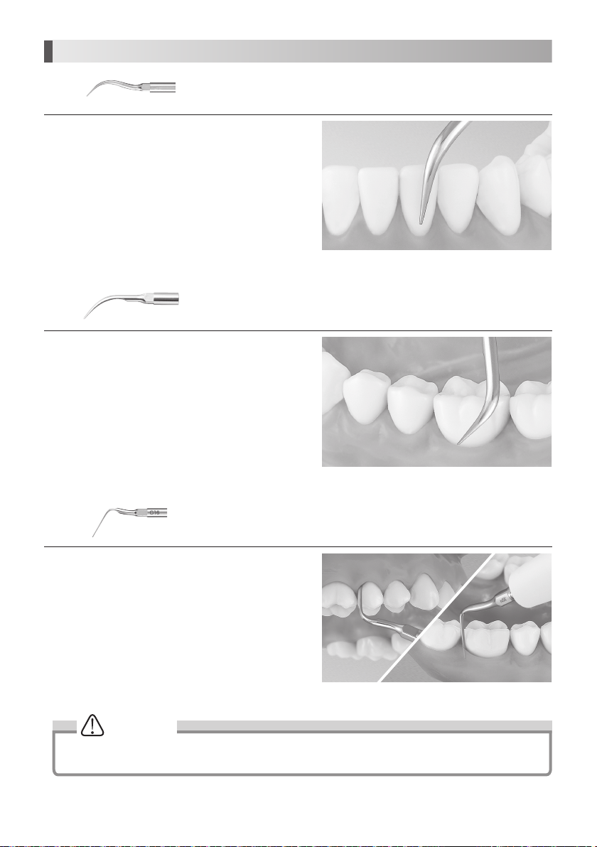
8. Provided Scaler Tips
G4
Apply the top of the Tip on the tooth plane and move it sideways
finely in the same way as G8 Tip. (Fig. 21)
The end of the Tip is thin and for supragingival fine scaling and interdental scaling. The
round cross-section allows tooth surfaces to be finished without causing damage.
Fig.21
G8
Apply the top of the Tip on the tooth plane and move it sideways
finely along the neck of tooth. (Fig. 22)
G16
Insert the top of the Tip into the periodontal pocket and move it
slowly. The top of the Tip is sharp so that it could remove tartar
on long coroner and retracted gingival. (Fig. 23)
Clean periodontal pocket at low power.
Removal of supragingival and interdental calculus. This Tip can be used in all
quadrants and is very useful for the removal of hard calculus.
Removal of supra and subgingival calculus. It provides easy access to interdental
spaces and narrow pockets.
Fig.22
Fig.23
CAUTION
Tip is article of consumption. We recommend periodical replacement. About time of replacement, check the Tip
Card.
12
Page 14
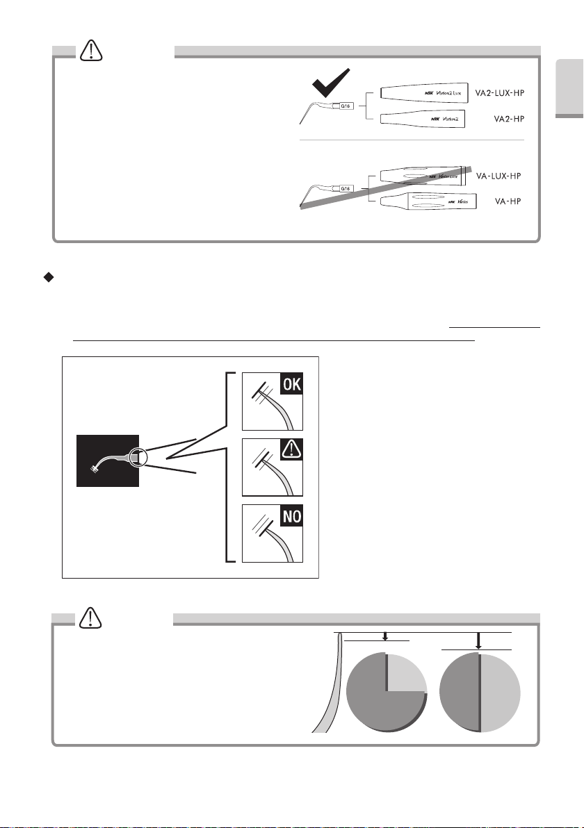
WARNING
Do not connect the supplied G16 Tip to a handpiece
other than a Varios2 handpiece (VA2-LUX-HP /
VA2-HP). Doing so may cause fracturing of the Tip or
scratches on the surface of the dentition, prosthesis,
etc. due to an increase in vibration amplitude (Fig. 24).
Fig.24
How to use the Tip Card
1) Place the neck of the Tip in the cut out.
2) Check wear of the Tip.
3) See the green, yellow and red line to check wear of the Tip. *See below what each color means. At NSK we recommend
to replace a Tip when the Tip meets the yellow line (wear of 1mm) to guarantee safe and effective use.
Tip Card
Green: No wear - Tip is OK
Tip replacement is not necessary.
English
CAUTION
Tips are consumables. The efficiency of dental scaling
decreases approximately 25% when the top of the Tip
wears 1 mm and approximately 50% when it wears 2 mm.
In addition, the vibration condition changes owing to the
wear, which may damage a patient’s tooth surface. Check
the Tip wear condition with the Tip Card periodically, and
replace the Tip with a new one in good time.
13
Yellow: Wear of 1mm - Tip is showing some wear
Tip replacement is recommended.
Red: Wear of 2mm - Tip is badly worn
Tip replacement is necessary.
Fig.25
1mm
25%
Decrease
Efficiency
2mm
50%
Decrease
Fig.26
Page 15
9. How to Use Tip Cover S (Option)
Grip the Tip Cover S and insert it to the Tip.
To remove, grip the Tip Cover S and the handpiece & pull. (Fig. 27)
The Tip Cover S is not designed for use as a Tip changing tool.
CAUTION
Carefully insert the Tip
into the Tip Cover S. Avoid
injuring the fingers.
Slit
10. Handpiece Holder
While the Handpiece is not in use, put the Handpiece in the
Handpiece Holder.
The Handpiece Holder is adjustable. (Fig. 28)
CAUTION
Do not put excessive load to the Handpiece Holder
to prevent from breaking down and deformation.
NOTICE
To prevent injury, always mount Scaler Tip Cover (S).
Slit
Tip
Tip Cover
Tip-Handpiece Joint
Fig.27
Handpiece Holder
Fig.28
11. Care and Maintenance
(1) Cleaning of Optic Fiber (Varios 970 LUX)
Wipe the debris off the end of the Optic Fibers at the
handpiece with alcohol soaked cotton swab. (Fig. 29)
CAUTION
Do not use any sharp pointed tools to clean the
Optic Fiber End Face. In case the light degridation,
contact your dealer.
Optic Fiber End Face
Fig.29
14
Page 16
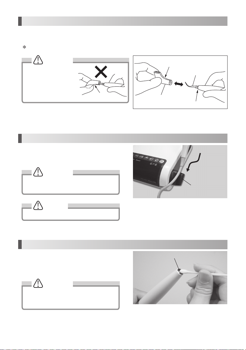
(2) Cleaning the Handpiece cord
Remove the handpiece after use on each patient and clean it
as described below.
1) Wipe the surface of the handpiece cord with a cloth soaked
in alcohol.
2) Carefully wipe the handpiece cord plug with an
alcohol-immersed cotton swab. If it is difficult to use a
cotton swab, carefully wipe with a towelette wound around
a thin stick-shaped object.
CAUTION
Do not use a sharp pointed stick or push the terminal part when cleaning the handpiece cord plug. Doing so may
cause damage, resulting in contact failure (Fig. 30).
Terminal part
English
Fig.30
(3) Changing O-Ring
• Handpiece Cord
An O-Ring is located in the Handpiece Cord Connector. Use a pointed tool to remove,
and mount new O-Ring into the groove. (Fig. 31)
* Optional O-Ring: Order Code D0310020080
• VA Bottle
Remove two O-Rings at the Bottle Joint with a pointed tool, and
mount new O-Rings into the grooves. (Fig. 32)
* O-Ring (Thick section) : Order code D0310075150
O-Ring (Thin section) : Order code D0312090100
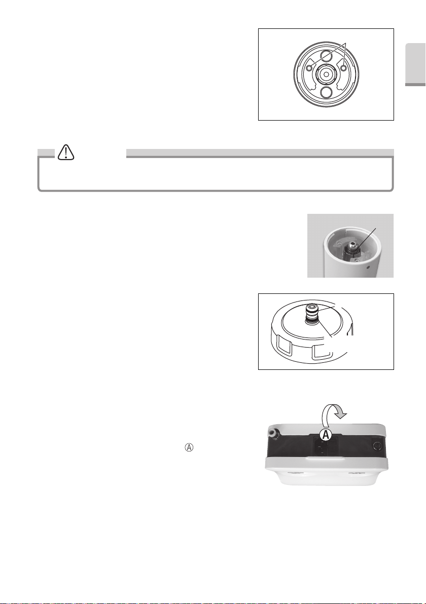
(4) Changing the Irrigation Pump
1) Remove the Bottle, the Power Cord, the Handpiece Cord and the
Foot Control from the Control Unit.
2) Turn back the Control Unit. Hang a finger on “
up the bottom cover to remove.
” point and pull
O-Ring
Fig.31
O-Ring (Thick section)
O-Ring (Thin section)
Fig.32
Fig.33
15
Page 17
Picture below is shows inside of the Control Unit.
Front Panel Side
R Pump Tube Joint
L Pump Tube Joint
R Bottle Bottle Joint
R PumpL Pump
Bottom Cover Hook
Bottom Cover (Back Side)
L Bottle Bottle Joint
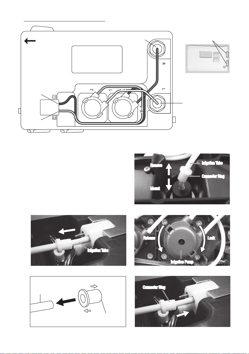
3) Remove the Irrigation Tube from the Control Unit. (Bottle side and Front Panel side.) (Fig. 35, 36)
4) Remove the Connector Ring from the Irrigation Tube. Do not dispose it. You can use the Rings to the replacement
Irrigation Pump.
5) Turn the Irrigation Pump counterclockwise until it clicks
Irrigation Tube
and pull it out. (Fig. 37)
6) Mount the Connector Ring to the new Irrigation Pump.
Observing Ring direction. (Fig. 38)
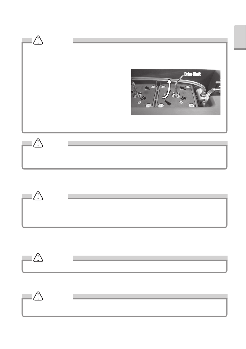
7) Align the replacement Irrigation Pump with the Drive Shaft.
Turn clockwise until it clicks. (Fig. 37)
8) Mount the Irrigation Tube opposite procedure of removing
Remove
Remove
Mount
Mount
Irrigation Tube
Connector Ring
Connector Ring
(Fig.35). Connector Ring should firmly into the Control Unit
until it stops. (Fig.39)
* Bottle side
Fig.34
Fig.35
* Front Panel side
Irrigation Tube
L/R Pump side
Irrigation Tube
Irrigation Tube
Control Unit side
Connector Ring
Fig.36
Fig.38
16
Release LockRelease Lock
Irrigation Pump
Irrigation Pump
Connector RingConnector Ring
* Front Panel side
Fig.37
Fig.39
Page 18
9) Align the Bottom Cover Hook and hole on the Control Unit. Mount the Bottom Cover.
* Optional Irrigation Pump: Order Code 10000643 (Not included the Connecter Ring.)
CAUTION
• If water is spilled out the irrigation pump, wipe it off and allow drying completely prior to use. If water gets inside
the irrigation pump the roller may slip and fail to pump.
• Before replacing the Irrigation Pump, wipe off excess water on pump and Drive Shaft. The wet drive shaft and
rollers can be slippery and cause improper operation.
• Wipe dirt and water off the Drive Shaft from bottom up.
(Fig.40)
• Insert the replacement Irrigation Pump into the Drive
Shaft straight (slow and soft) to prevent damaging rollers
in pump.
• Run the replaced Irrigation Pump about 10 seconds
on largest setting of Water Volume before operation to
adopt Irrigation Tube to new pump.
• Ensure Irrigation tube has no kink or twists If tube is set
incorrectly, Irrigation Water may not come out.
• Do not pull the tube when the bottom cover is closed.
Drive ShaftDrive Shaft
NOTICE
• Perform periodical cleaning for the Drive Shaft with socked alcohol cloth. Dirt on Drive Shaft may cause an
incorrect pump operation.
• The pump is consumable. If the irrigation volume decreases markedly, replace pump.
(5) Auto Cleaning (Cleaning of Irrigation Tube (Use of Bottle))
NOTICE
• After each use, remove all the disinfectant solution and perform "Auto Cleaning" procedure. If you have not
cleaned the system, it may become dirt disinfectant. And it is stuck in the tubing or some of the metal parts may
be rusted.
• During Auto Cleaning, water comes out from the handpiece. Perform cleaning after turning handpiece into a cup.
English
Fig.40
1) Remove the 2 Bottles from the Control Unit.
2) Clean inside of the Bottle.
3) Half fill the bottle with purified water (DO NOT USE SALINE)
CAUTION
Use only distilled water for cleaning.
4) Install the cap on the Bottle. Install the Bottle Joint into the Bottle Base Connector. Install it until clicks into place.
Improper connection may cause water leakage. Make sure the connection is tight.
CAUTION
• Perform Auto-Cleaning without tip.
• Make sure the handpiece and handpiece cord are firmly attached.
17
Page 19
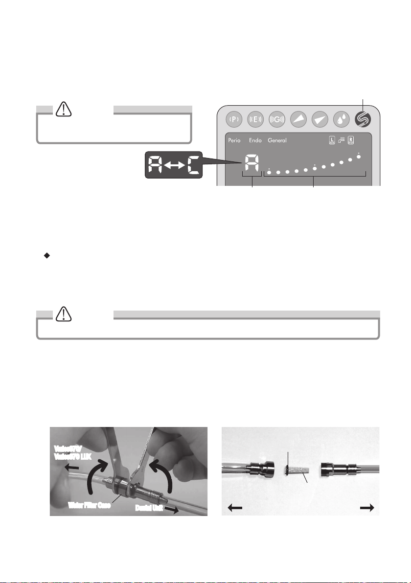
5) To perform the Auto-Cleaning, keep pressing the Auto-Cleaning Key (more than 1 second).It takes 30 seconds per
bottle to clean The Numerical Display will alternately displays “A” and “C”, the Bar Graph displays time remaining.
Single display (Bar Graph Display) is 6 second. When five displays of Bar Graph disappeared, Bottle will be changing
the other side.
To cancel the Auto-Cleaning, press Auto-Cleaning Key again.
Auto-Cleaning Key
NOTICE
During Auto-Cleaning, LED of the handpiece
does not illuminate. (Varios 970 LUX)
Numerical Display Bar Graph
6) When the Auto-Cleaning is finished, the Control Unit returns to the settings prior to cleaning. Remove the both bottles
from the Control Unit by pulling straight up. Clean thoroughly rinse and dry.
Following method is also available for cleaning. (Manual Cleaning)
1) Remove the Bottle from the Control Unit.
2) Open the cap of the cleaned Bottle and fill it with distilled water.
3) Close the cap firmly and insert the Bottle Joint into the Bottle Base Connector on the Control Unit until it clicks.
4) Operate the Control Unit about 30 seconds with water supply at maximum setting.
NOTICE
The Control Unit does not perform in Auto-Cleaning in Tap Water.
(6) Changing Water Filter (Option)
If you use Tap Water, change the Water Filter as it may necessary.
1) Close the water valve of the dental unit.
2) Mount two Spanner Wrenches (5x8) and turn those as shown in Fig.42.
3) When the Water Filter case is separated, the Water Filter can be removed as shown in Fig.43.
4) Replace with new ( Order Code U387042 ) and reassemble the filter in the reverse order.
Varios970/
Varios970 LUX
O-Ring
Fig.41
Water Filter Case
Dental Unit
Fig.42
Water Filter
Varios970/Varios970 LUX Dental Unit
Fig.43
18
Page 20
12. Sterilization
Only handpiece can be washed via Thermo Disinfector.
• Autoclave sterilization is recommended.
• Autoclave sterilization required first time you use and after each patient as noted below. Take handpiece out of the
packing bag before sterilization.
• ONLY the Tip, Handpiece and Tip Wrench can be autoclaved.
Autoclave Procedure
1) Remove the Tip after use. (Refer to 6. Mounting and Removing Tip)
2)
Wipe dirt and debris from the products, and wipe clean with alcohol-immersed cotton swab or cloth. For handpiece, use
MinutenWipes (ALPRO) to wipe. Do not use a wire brush.
3) Insert those into the Sterilization Case or an autoclave pouch. Seal the pouch.
4) Autoclavable up to max. 135˚C.
Ex.) Autoclave for 20 min. at 121˚C, or 15 min. at 132˚C.
5) Keep the products in the Sterilization Case or autoclave pouch to keep it clean until you use it.
* Sterilization at 121°C for more than 15 minutes is recommended by ISO17664 and EN ISO17665-1.
CAUTION
• Do not sterilize by ultraviolet ray. The handpiece could discolor.
• If autoclaved with other instruments stained with chemical solution, it could strip the plating and make the surface
black.
• Do not autoclave any parts (the Control Unit, Power Cord, Bottle, Foot Control, Handpiece Cord, O-Ring). Other
than those that can be subjected to autoclave sterilization. Perform alcohol disinfection to the Control Unit, Power
Cord, Foot Control, Handpiece Cord including after every patient.
• Do not wipe with, or clean or immerse in, high acid water or sterilizing solutions.
English
NOTICE
Repeated autoclaving may cause the handpiece to become discolored due to heat. However, this is due to
properties of the product and is not a problem in terms of quality.
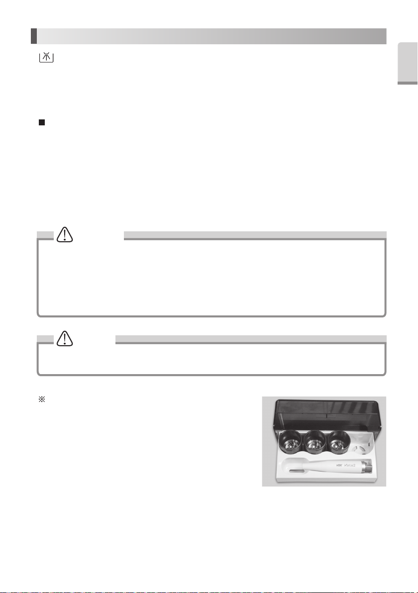
Sterilization Case
The Handpiece, Tip and Tip Wrench can be sterilized together using
Sterilization Case.
1) Remove the Tip after use. (Refer to 6. Mounting and Removing Tip)
2) Set the Tip Wrench with Tip into the Sterilization Case. (You can set four
Tip Wrenches and Tips at once).
3) Remove handpiece from the Handpiece Cord, and clean.
4) Set the handpiece into the Sterilization Case.
5) Autoclavable up to max. 135˚C.
ex.) Autoclave for 20 min. at 121˚C, or 15 min. at 132˚C.
6) Keep the products in the Sterilization Case or autoclave pouch to keep it clean until you use it.
19
Fig.44
Page 21
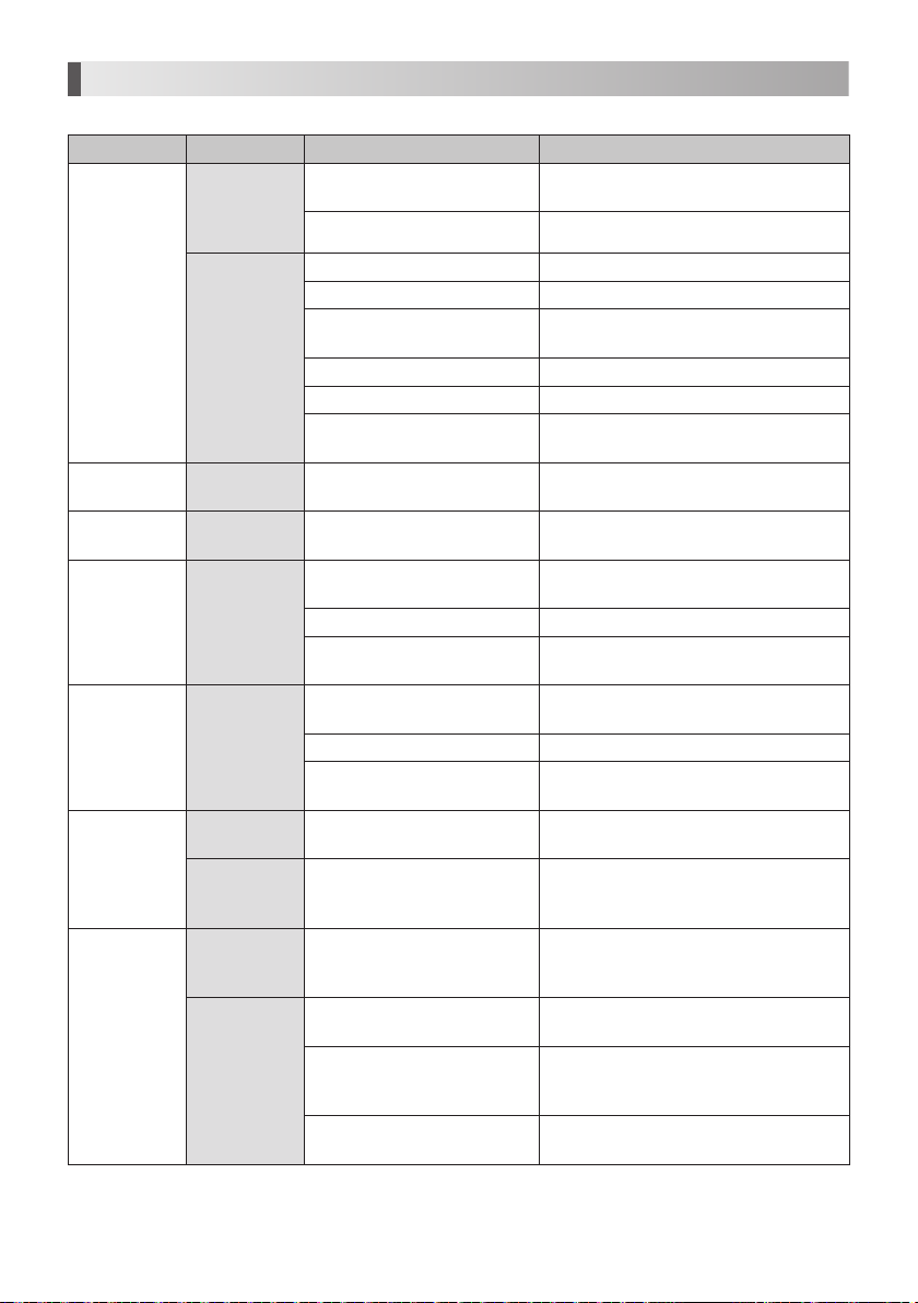
13. Troubleshooting
When trouble is found, please check the followings prior to consulting your dealer.
Problem Probable Cause Cause Solution
The Power Cord or the Jack is
disconnected.
The Fuse is burned out. Contact dealer.*
The Tip is not tightened firmly. Tighten the Tip until the Tip Wrench clicks.
Worn Tip. Replace the Tip.
Power has not been correctly
adjusted for the Tip.
The Foot Control is disconnected. Connect the Foot Control correctly.
Failure of vibrator in the handpiece. Contact dealer.*
Failure of internal components of
the Foot Control.
Power has not been properly
adjusted for the Tip.
Power has not been properly
adjusted for the Tip.
The Tip is not tightened firmly. Tighten the Tip until the Tip Wrench clicks.
Failure of vibration in the handpiece
or the Control Unit.
Power has not been properly
adjusted for the Tip.
The Tip is not tightened firmly. Tighten the Tip until the Tip Wrench clicks.
Failure of vibration in the handpiece
or the Control Unit.
The tube twisted. Straighten the twisted Irrigation Tube.
Time to replace Irrigation Pump.
(Approx. 500hours after used.)
—
The Water Adjustment Knob is
closed.
Disconnected Irrigation supply at
low volume range. (less than 10ml/
min.)
The Water Filter is clogged.
Correctly insert the Power Cord or the Jack.
Adjust the power on the Power Guide or Tip
case label. Do not exceed.
Contact dealer.*
Adjust the power level the Power Guide or Tip
case label. Do not exceed.
Adjust the power level on the Power Guide or
Tip case label. Do not exceed.
Contact dealer.*
Adjust the power level on the Power Guide or
Tip case label. Do not exceed.
Contact dealer.*
Replace with new Irrigation Pump (Refer to 11.
(4) Changing the Irrigation Pump).
Check the water circuitry and supply to the
Control Unit. Water pressure : 0.1-0.5MPa
(1-5kgf/cm
Turn the Water Adjustment Knob and adjust to
the appropriate volume.
No problem. Turn the Water Adjustment Knob
and increase the Irrigation volume.
Replace with new Water Filter (Refer to 11. (6)
Changing Water Filter (Option) ).
2
)
No / Poor
vibration.
The Tip is bent
or broken.
The Tip is flying
away.
Noise from the
handpiece.
The handpiece is
overheating.
No Irrigation
supply and/or
unstable
Irrigation supply
(Use of Bottle)
No / Poor water.
(Use of Tap
Water)
The Front Panel
does not light,
even if the Power
Switch is ON.
The Tip does
not generate
vibration, in spite
of depressing
the Foot Control.
—
— The Tip is not tightened firmly. Tighten the Tip until the Tip Wrench clicks.
—
—
The Irrigation
Pump is running.
The Irrigation
Pump is
stopping.
The water does
not reach to the
Control Unit.
Check to see if
water reaches
the Control Unit.
20
Page 22
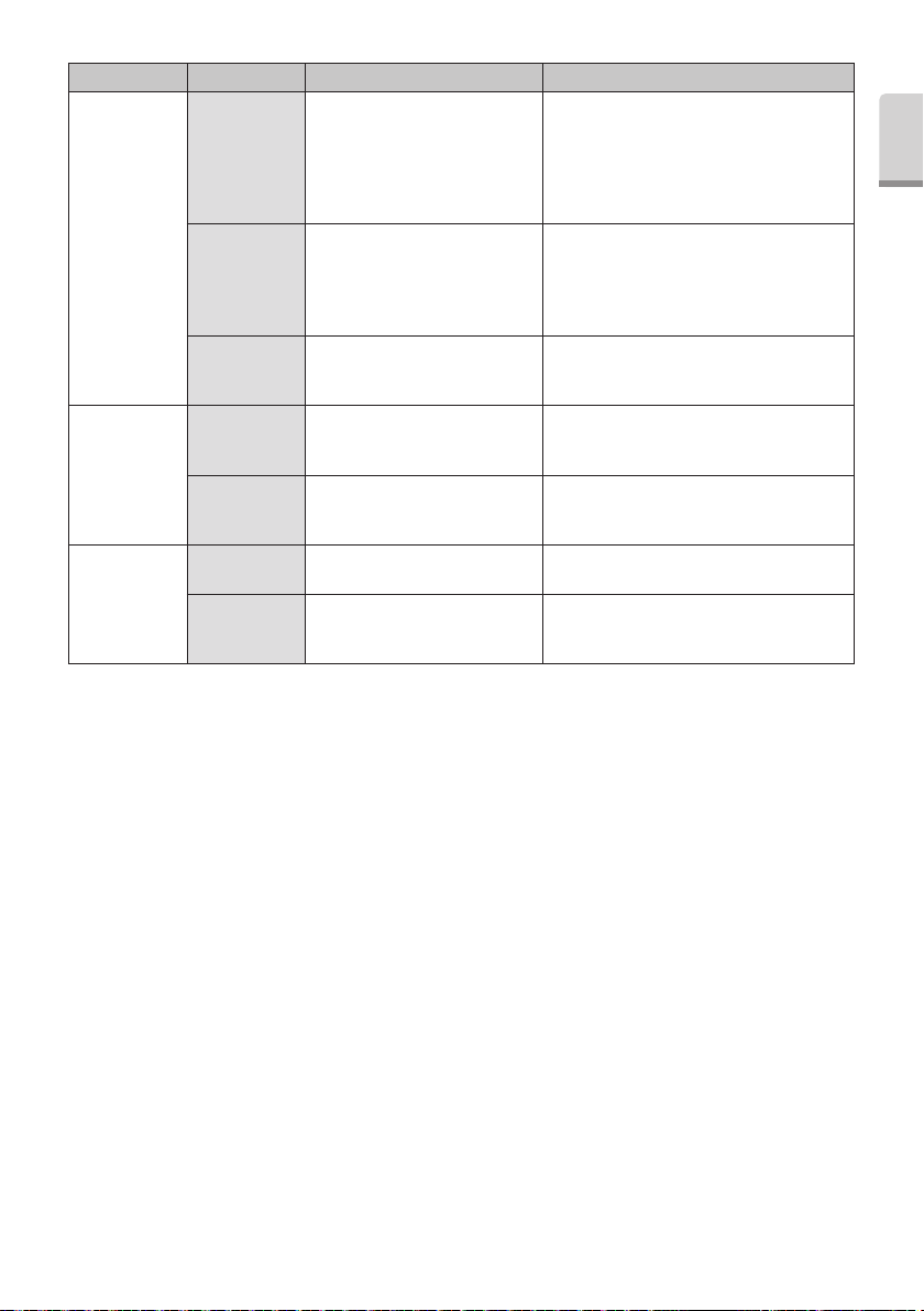
Problem Probable Cause Cause Solution
Water is leaking
from the joint
between the
Irrigation Tube
The Irrigation Tube is not connected
correctly.
Firmly insert the Irrigation Tube into the Irrigation
Connector inmost.
and the Irrigation
Connector.
Water leakage.
Water is leaking
from the joint
between the
handpiece and
O-Ring at the handpiece cord is
worn or damaged.
Replace with new O-Ring (Refer to 11 (3)
Changing O-Ring •Handpiece Cord).
the cord.
Water is leaking
from the Control
Unit.
Tip oscillates, but
Handpiece
LED does not
illuminate.
(Varios 970 LUX)
Handpiece LED
turns on and off.
Tip oscillates, but
Handpiece LED
does not turn on.
Beeping while
power on.
Start Beeping
Beeping while
stopping
vibration of Tips.
* Repairs cannot be made by the customer.
The water circuitry in the Control
Unit is damaged.
The handpiece is not connected into
the Handpiece Cord correctly.
Disconnection in the Handpiece
Cord, or failure in the Control Unit.
Contact dealer.*
Firmly insert the handpiece into the Handpiece
Cord inmost.
Contact dealer.*
Depress Foot Control. Release the Foot Control.
Abnormal heating of the Control
Unit.
Stop the operation and leave until Control Unit
becomes cool.
English
21
Page 23
14. Specifications
Type NE255
Power Source
AC120V 50/60Hz
AC230V 50/60Hz
Vibration Frequency 28-32kHz
Maximum Output 11W
Rated Power 29VA
2
Water Pressure 0.1-0.5MPa (1-5kgf/cm
Lighting
Varios 970 : No
Varios 970 LUX : Yes
)
Bottle Volume 400mL (Per Bottle)
Dimensions W160 x D270 x H190mm (Including Bottle)
Weight 2.1kg (Except attachment)
Temperature 0 - 40 ˚C (The liquid must not freeze up)
Use Environment
Humidity 30 - 75 %
Atmospheric pressure 700 - 1060 hPa
Temperature -10 - 60 ˚C
Store Environment
Humidity 10 - 85 %
Atmospheric pressure 500 - 1060 hPa
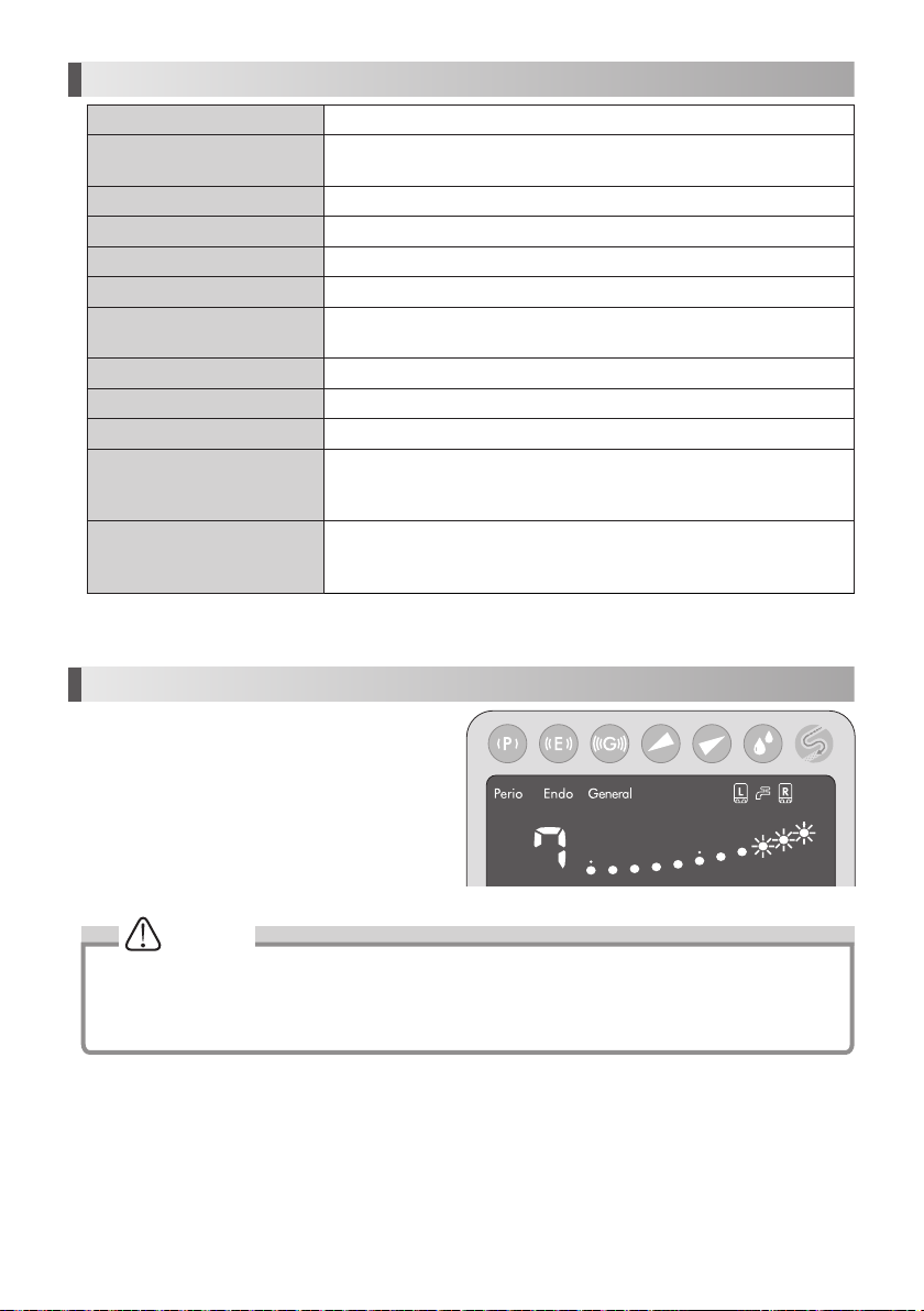
15. Protection Circuit
It may overheat inside when you use this Control Unit in
more than Power 8 at G mode for long time.
In this case, Protection Circuit reduces the Power
automatically. (Power 7)
Bar Graph Indicator from 8 to 10 flashes. (Fig.45)
After Protection Circuit is released, the flashes stop.
However, Power Level can not automatically increase. If
needed, increase manually.
NOTICE
• During Protection Circuit function (during Bar Graph Indicator flash), the Control Unit can not increase the Power
Level.
• If Power Level decreases less than 7, Bar Graph Indicator stops flashing. However, it the Power increase more
than 8, flashes it again.
22
Fig.45
Page 24
16. Error Code
If an operational problem occurs numerical Display shows the error code to allow an immediate problem diagnosis.
Error Code Error Check / Remedy
E 0 Self-Check Error Contact dealer.
E 1 Circuit Failure Contact dealer.
E 7 Does not vibrate Contact dealer.
Confirm connection of the handpiece.
E 9 Handpiece Self Check Error
E 10 Circuit Failure Contact dealer.
*“E” and the number alternately display on the Display.
Power on the Control Unit again.
Leave the Control Unit until it become cool down and powers it again.
When an error can not be eliminated, Contact dealer.
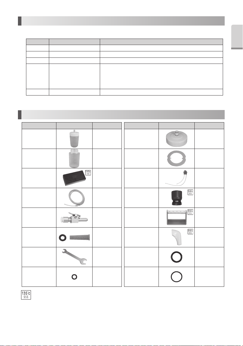
17. Spare Parts
Model Products Oeder Code Model Products Oeder Code
VA Bottle Set 400 Z1047002
VA Bottle 400 20000947
Sterilization Case Z1035001
Water Tube Set U387040
VA Bottle Cap 400 10000652
Gasket Z1047350
Irrigation Pump 10000643
Tip Wrench
(CR-10)
English
Z221076
Water Connector U387030
Water Filter U387042
Spanner Wrench
(5x8)
O-Ring
(for Handpiece
Cord)
Autoclavable at 135˚C max.
Y1001301
D0310020080
Tip Holder Z221A080
Tip Cover S Z217851
O-Ring
(Thick section)
(For VA Bottle)
O-Ring
(Thin section)
(For VA Bottle)
23
D0310075150
D0312090100
Page 25
18. Disposing product
Consult with dealer from whom you purchased it about waste disposal.
19. Warranty
Manufacturer warrants its products to the original purchaser against defects in material and workmanship under normal
practices of installation, use and servicing. Such expendable items as O-Rings and Irrigation Pump are not covered by this
warranty.
Symbols
TUV Rhineland of North America is a Nationally Recognized Testing Laboratory (NRTL) in the United States and is accredited by
the Standards Council of Canada to certify electro-medical products with Canadian National Standards.
Follow the waste of electric and electronic equipment (WEEE) Directive (2012/19/EU) to dispose of the product and
accessories.
Consult operation instructions.
Manufacturer.
This conforms to CE European Directive of “Medical equipment directive 93/42/EEC.”
Type BF applied part. Authorised representative in the European community.
Protected against vertically falling water drops. Autoclavable up to Max.135°C. *for detail see Sterilization.
This product can be cleaned and disinfected with a Thermo-Disinfector.
Marking on the outside of Equipment or Equipment parts that include RF transmitters or that apply RF electromagnetic energy
for diagnosis or treatment.
GS1 DataMatrix for Unique Device Identifier.
Guidance and manufacturer's declaration - electromagnetic emissions
The Varios 970 / Varios 970 LUX is intended for use in the electromagnetic environment specified below. The customer or the user of the Varios 970 / Varios 970 LUX
should assure that is used in such an environment.
Emissions test Compliance Electromagnetic environment - guidance
RF emissions
CISPR11/EN55011
RF emmissions
CISPR11/EN55011
Harmonic emissions
EN/IEC61000-3-2
Voltage fluctuations/flicker emissions
EN/IEC61000-3-3
Group 1
class B
class A
Complies
The Varios 970 / Varios 970 LUX uses RF energy only for its internal function. Therefore,
its RF emissions are very low and are not likely to cause any interference in nearby
electronic equipment.
The Varios 970 / Varios 970 LUX is suitable for use in all establishments, including
domestic establishments and those directly connected to the public low-voltage power
supply network that supply network that supplies buildings used for domestic purposes.
24
Page 26
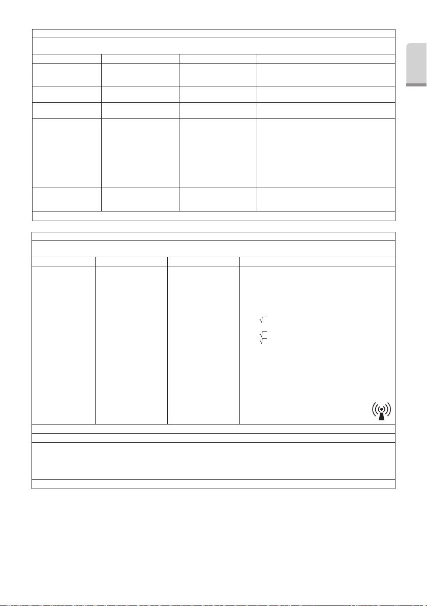
Guidance and manufacturer's declaration - electromagnetic immunity
The Varios 970 / Varios 970 LUX is intended for use in the electromagnetic environment specified below. The customer or the user of the Varios 970 / Varios 970 LUX
should assure that it is used in such an environment.
Immunity test EN/IEC60601 test level Compliance level Electromagnetic environment - guidance
Electrostatic discharge (ESD)
EN/IEC61000-4-2
Electrical fast transient/burst
EN/IEC61000-4-4
Surge
EN/IEC61000-4-5
Voltage dips, short
interruptions and voltage
variations on power supply
input lines
EN/IEC61000-4-11
Power frequency (50/60Hz)
magnetic field
EN/IEC61000-4-8
NOTE: Ut is the a.c. mains voltage prior to application of the test level.
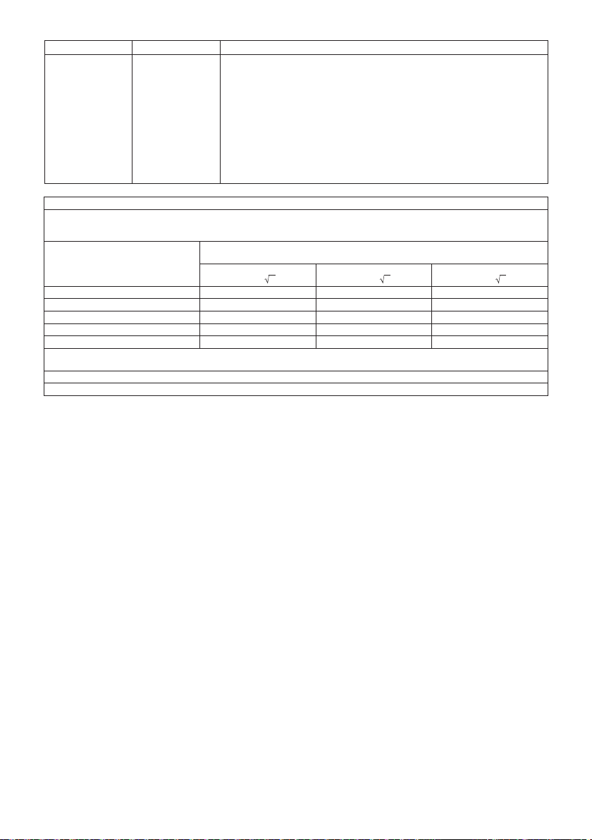
Guidance and manufacturer's declaration - electromagnetic immunity
The Varios 970 / Varios 970 LUX is intended for use in the electromagnetic environment specified below. The customer or the user of the Varios 970 / Varios 970 LUX
should assure that it is used in such an environment.
Immunity test EN/IEC60601 test level Compliance level Electromagnetic environment - guidance
Conducted RF
EN/IEC61000-4-6
Radiated RF
EN/IEC61000-4-3
NOTE 1 At 80MHz and 800MHz, the higher frequency range applies.
NOTE 2 These guidelines may not apply in all situations. Electromagnetic propagation is affected by absorption and reflection from structures, objects and people.
a Field strengths from fixed transmitters, such as base stations for radio (cellular/cordless) telephones and land mobiles radios, amateur radio, AM and FM
radio broadcast and TV broadcast cannot be predicted theoretically with accuracy. To assess the electromagnetic environment due to fixed RF transmitters, an
electromagnetic site survey should be considered. If the measured field strength in the location in which the Varios 970 / Varios 970 LUX is used exceeds the
applicable RF compliance level above, the Varios 970 / Varios 970 LUX should be observed to verity normal operation. If abnormal performance is observed,
additional measures may be necessary, such as reorienting or relocating the Varios 970 / Varios 970 LUX.
b Over the frequency range 150kHz to 80MHz, field strengths should be less than 3 V/m.
±6kV contact
±8kV air
±2kV for power supply lines
±1kV for input/output
±1kV line(s) to line(s)
±2kV line(s) to earth
<5% Ut (>95% dip in Ut)
for 0.5 cycle
40% Ut (60% dip in Ut)
for 5 cycles
70% Ut (30% dip in Ut)
for 25 cycles
<5% Ut (>95% dip in Ut)
for 5 secs
3 A/m 3 A/m Power frequency magnetic fields should be at levels
3Vrms
150 kHz to 80MHz
3V/m
80MHz to 2.5 GHz
±6kV contact
±8kV air
±2kV for power supply lines
±1kV for input/output
±1kV line(s) to line(s)
±2kV line(s) to earth
<5% Ut(>95% dip in Ut)
for 0.5 cycle
40% Ut (60% dip in Ut)
for 5 cycles
70% Ut (30% dip in Ut)
for 25 cycles
<5% Ut (>95% dip in Ut)
for 5 sec
3Vrms
3V/m
Floors should be wood, concrete or ceramic tile. If floors are
covered with synthetic material, the relative humidity should
be at least 30%.
Mains power quality should be that of a typical commercial or
hospital environment.
Mains power quality should be that of a typical commercial or
hospital environment.
Mains power quality should be that of a typical commercial
or hospital environment. If the user of the Varios 970 / Varios
970 LUX requires continued operation during power mains
interruptions, it is recommended that the Varios 970 / Varios
970 LUX be powered from an uninterruptible power supply or
a battery.
characteristic of a typical location in a typical commercial or
hospital environment.
Portable and mobile RF communications equipment should be used
no closer to any part of the Varios 970 / Varios 970 LUX, including
cables, than the recommended separation distance calculated from
the equation applicable to the frequency of the transmitter.
Recommended separation distance
d = 1.2 P
d = 1.2 P 80MHz to 800MHz
d = 2.3 P 800MHz to 2.5GHz
Where P is the maximum output power rating of the transmitter in
watts (W) according to the transmitter manufacturer and d is the
recommended separation distance in meters (m).
Field strengths from fixed RF transmitters as determined by an
electromagnetic site survey, should be less than the compliance level
in each frequency range.
Interference may occur in the vicinity of equipment
marked with the following symbol:
English
25
Page 27
Cables and accessories Maximum length Complies with
Handpiece cord
Foot Control
AC Power Cord
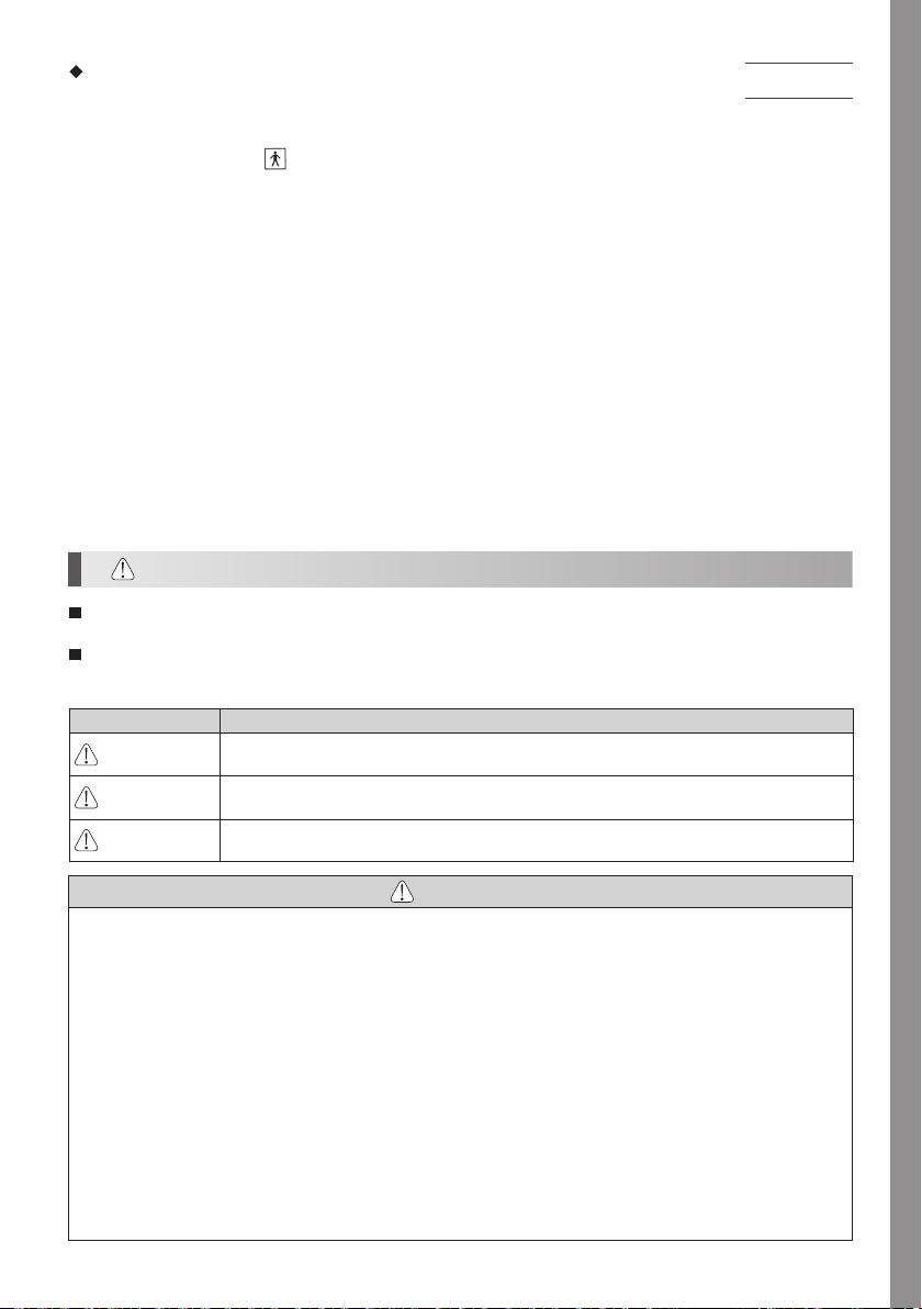
Recommended separation distances between portable and mobile RF communications equipment and the Varios 970 / Varios 970 LUX.
The Varios 970 / Varios 970 LUX is intended for use in an electromagnetic environment in which radiated RF disturbances are controlled. The customer or the user of
the Varios 970 / Varios 970 LUX can help prevent electromagnetic interference by maintaining a minimum distance between portable and mobile RF communications
equipment (transmitters) and the Varios 970 / Varios 970 LUX as recommended below, according to the maximum output power of the communications equipment.
Rated maximum output power of transmitter
For transmitters rated at a maximum output power not listed above, the recommended separation distance d in meters (m) can be estimated using the equation
applicable to the frequency of the transmitter, where P is the maximum output power rating of the transmitter in watts (W) according to the transmitter manufacturer.
NOTE 1 At 80 MHz and 800 MHz, the separation distance for the higher frequency range applies.
NOTE 2 These guidelines may not apply in all situations. Electromagnetic propagation is affected by absorption and reflection from structures, objects and people.
2 m
2 m
2 m
W
0.01 0.12 0.12 0.23
0.1 0.38 0.38 0.73
1 1.2 1.2 2.3
10 3.8 3.8 7.3
100 12 12 23
RF emissions, CISPR11, EN55011
Harmonic emissions,
Voltage fluctuations/ flicker emission,
Electrostatic discharge (ESD)
Electric fast transient / burst
Surge
Voltage dips, short interruptions and voltage variations on power supply input lines
Power frequency(50/60Hz) magnetic field
Conducted RF
Radiated RF
150kHz to 80MHz
d=1.2 P
Separation distance according to frequency of transmitter
m
80MHz to 800MHz
d=1.2 P
Class B/ Group 1
EN/IEC61000-3-2
EN/IEC61000-3-3
EN/IEC61000-4-2
EN/IEC61000-4-4
EN/IEC61000-4-5
EN/IEC61000-4-11
EN/IEC61000-4-8
EN/IEC61000-4-6
EN/IEC61000-4-3
800MHz to 2.5GHz
d=2.3 P
26
Page 28
Klassifizierung der Geräte
• Schutzart gegen Stromschlag :
– Geräteklasse I
• Schutzart gegen Stromschlag :
– Anwendungsteil Typ BF:
• Vom Hersteller empfohlenes Verfahren zum Sterilisieren oder Desinfizieren :
– Siehe 12. Sterilisation
• Schutzart gegen Eindringen von Wasser gemäß der Beschreibung in der aktuellen Ausgabe von IECD 60529:
– Fußschalter : IPX1 (gegen senkrecht herunterfallende Wassertropfen geschützt)
• Grad der Anwendungssicherheit bei Verwendung einer entflammbaren Betäubungsmittelmischung mit Luft oder mit
Sauerstoff oder Lachgas :
– GERÄT ist nicht zur Verwendung mit einer entflammbaren Betäubungsmittelmischung mit Luft oder mit Sauerstoff oder
Lachgas geeignet.
• Betriebsart :
– Dauerbetrieb
Deutsch
Bestimmungsgemäßer Gebrauch
Dieses Gerät ist nur zum Gebrauch in Zahnkliniken / Zahnarztpraxen bestimmt. Dieses Gerät erzeugt Ultraschallwellen, die
für Dentalanwendungen wie zum Beispiel Scaling, Wurzelkanalbehandlung, Paradontalbehandlung und Zahnpräparationen
bestimmt sind.
1. Vorsichtsmaßregeln für Handhabung und Bedienung
Lesen Sie diese Vorsichtsmaßregeln sorgfältig durch und verwenden Sie das Gerät nur bestimmungsgemäß bzw. gemäß
der Anleitung.
Die Sicherheitsvorschriften dienen zum Vermeiden möglicher Gefahren, die zu Verletzungen oder einer Beschädigung des
Geräts führen könnten. Die Sicherheitsvorschriften werden entsprechend des Risikogrades wie folgt eingestuft.
KLASSE RISIKOGRAD
WARNUNG
ACHTUNG
HINWEIS
Eine Gefahr, die zu Verletzungen oder zu einer Beschädigung des Geräts führen können, wenn die
Sicherheitsvorschriften nicht befolgt werden.
Eine Gefahr, die zu leichten oder mittelschweren Verletzungen oder einer Beschädigung des Geräts
führen können, wenn die Sicherheitsvorschriften nicht befolgt werden.
Allgemeine Informationen für den sicheren Betrieb des Geräts.
WARNUNG
• Stecken Sie das Anschlusskabel nicht mit nassen Händen aus, um einen Stromschlag zu vermeiden.
• Achten Sie darauf, dass die Steuereinheit nicht mit Wasser in Berührung kommt, da dies zu einem Kurzschluss und einem
Stromschlag führen kann.
• Berühren Sie das hintere Ende des Handstücks nicht, wo elektrische Anschlüsse mit dem Kabel verbunden sind. Dies
könnte zu einem Stromschlag führen.
• Wenn Sie vor oder während des Betriebs des Geräts eine Anormalität wie z.B. Vibrationen, Wärmeentwicklung, unnormale
Geräusche etc. feststellen, schalten Sie das Geärt sofort ab.
• Verwenden Sie eine geerdete Steckdose. Es kann zu einem Stromschlag kommen, wenn Sie eine andere verwenden.
• Betätigen Sie den Hauptschalter nicht grundlos, dies könnte eine Sicherung auslösen.
• Dieses Gerät ist ein medizinisches Elektrogerät. Die EMK (elektromagnetische Kompatibilität) wird in der
Begleitdokumentation beschrieben.
• Tragbare und mobile RF-Kommunikationsgeräte können das medizinische Elektrogerät beeinträchtigen. Verwenden Sie
keine RF-Geräte in der Umgebung des Geräts.
• Sehen Sie beim Installieren des Geräts Platz von circa 10 cm um die Steuereinheit herum vor, damit der Zulauf und das
Anschlusskabel einfach zugänglich sind.
27
Page 29
• Denken Sie beim Verwenden des Geräts stets an die Sicherheit des Patienten.
• Es ist zur Verwendung durch medizinisches Fachpersonal wie zum Beispiel durch einen Arzt/eine Ärztin oder einen
Dentalhygieniker /eine Dentalhygienikerin bestimmt.
• Überprüfen Sie vor dem Verwenden die Vibrationen außerhalb des Mundes des Patienten. Sollte Ihnen etwas unnormal
vorkommen, stellen Sie die Verwendung sofort ein und setzen Sie sich mit Ihrem Händler in Verbindung.
• Die Steuereinheit / das Handstück darf nicht fallen gelassen oder starken Erschütterungen ausgesetzt werden.
• Verwenden Sie nur echte NSK-Aufsätze für den NSK Varios Ultraschallscaler (Varios 970 oder Varios 970 LUX). Probleme
wie zum Beispiel eine Beschädigung, ein Ausfall oder eine Störung von Handstücken aufgrund der Verwendung von
anderen als NSK-Aufsätzen werden von der Garantie nicht abgedeckt. Im Folgenden finden Sie mögliche Fehler, die beim
Verwenden von anderen als NSK-Aufsätzen auftreten können.
– Schwingungsbruch, verursacht durch die Verwendung nicht konformer Schrauben.
– Patient verschluckt versehentlich beschädigte Aufsätze.
– Beschädigung des Gewindes am Handstück.
– Sie müssen den Aufsatz innerhalb des in der Leistungsrichtlinie für Aufsätze beschriebenen Leistungsbereichs
verwenden. Wenn Sie ihn außerhalb des Leistungsbereichs verwenden, könnte der Aufsatz abbrechen oder eine
Operationsstelle geschädigt werden.
• Verwenden Sie immer ausreichend Wasser (Kühlmittel), da es sonst zu einer Schädigung der Zahnoberfläche und einer
Überhitzung des Handstücks kommen kann.
• Sterilisieren Sie es nicht mit ultraviolettem Licht. Das Handstück könnte sich verfärben.
• Sterilisieren Sie den Aufsatz, das Handstück und den Drehmomentschlüssel mit dem Autoklaven. Wischen Sie die Steuereinheit,
das Wechselstrom-Anschlusskabel, den Fußschalter und das Handstückkabel mit DSH gelisteter Desinfektionslösung ab.
• Wenn chemische Lösungen, Lösungsmittel oder antiseptische Lösung an dieses Gerät gelangen, wischen Sie es sofort ab.
Sonst kann es zu einer Verfärbung oder Verformung kommen.
• Das Handstück/die Steuereinheit darf nicht auseinandergenommen oder verändert werden.
• Halten Sie das Gerät von Patienten mit einem Herzschrittmacher fern.
• Halten Sie das Gerät von explosiven Stoffen und entflammbarem Material fern. Verwenden Sie es nicht für Patienten, die
mit Lachgas betäubt werden.
• Verwenden Sie eine Sicherung mit entsprechender Bemessung (120 V: T630 mAL 250 V, 230 V: T315 mAL 250 V).
• Für dieses Gerät gelten besondere Vorsichtsmaßregeln bezüglich der EMK und es muss entsprechend den EMK-Daten
installiert und in Betrieb genommen werden.
• Die Verwendung von anderen ZUBEHÖRTEILEN, Wandlern und Kabeln als den hier angegebenen kann, mit Ausnahme
von Wandlern und Kabeln, die vom Gerätehersteller als Ersatzteile für Einbauteile verkauft werden, zu einer vermehrten
EMISSION oder einer verringerten STÖRFESTIGKEIT dieses Geräts führen.
• Dieses Gerät sollte nicht direkt neben, auf oder unter anderen Geräten aufgestellt werden, und wenn es direkt neben,
unter oder auf anderen Geräten verwendet werden muss, muss sichergestellt werden, dass das Gerät in der Konfiguration,
in der es verwendet werden soll, normal funktioniert.
• Wenn nach dem Autoklavieren noch Wassertropfen am Handstück, wischen
Sie sie ab. Wenn Sie sie nicht abwischen, können sich Flecken bilden.
• Dieses Gerät darf nicht vom Patienten benutzt werden.
• Eine zuverlässige Erdung kann nur erreicht werden, wenn die
Ausrüstung an einer Anschlussdose mit der Kennzeichnung "Nur
Krankenhaus" oder "Krankenhaus-Grad" angeschlossen wird.
• Wenden Sie keine zu hohe Leistung an der Spitze an, denn dies könnte
den Zahn beschädigen.
Netzstecker unten wird in Nordamerika verwendet.
Steckertyp NEMA 5-15P (Typ Krankenhaus-Grad)
ACHTUNG
• Während des Betriebes können das Handstück und das Handstückkabel Computer und LAB-Kabel beeinflussen. Es kann
zu einem Rauschen kommen, wenn es neben einem Rundfunkgerät betrieben wird.
• Stellen Sie sicher, dass der Hauptschalter am Gerät nach der Benutzung ausgeschaltet wird. Ziehen Sie den Netzstecker
und lassen Sie das Wasser aus dem Inneren der Steuereinheit ab, wenn sie für längere Zeit nicht verwendet wird.
• Der Benutzer ist für die Bedienung, Wartung und Inspektion verantwortlich.
• Reinigen/ sterilisieren Sie das Gerät direkt nach dem Verwenden. Dann lagern Sie es ein. Wenn Blut etc. darauf verbleibt,
kann dies zu einem Ausfall führen.
• Verwenden Sie zum Reinigen MinutenWipes (ALPRO) , um die Oberfläche des Handstücks abzuwischen. Die Verwendung
anderer Chemikalien als dieser kann dazu führen, dass sich das Handstück verfärbt, bricht usw.
28
Page 30

• Wenn Sie das Gerät längere Zeit nicht verwendet haben und es erneut einsetzen möchten, überprüfen Sie es vor dem
Einsatz auf seine Funktionstüchtigkeit.
• Schauen Sie nicht in die LED-Lampe und lassen Sie die Patienten nicht hineinschauen. Dies kann zu einer Schädigung der Augen führen.
• Dieses Gerät kann für Patienten jeden Alters (außer Kleinkinder), Geschlechts, Gewichts und jeder Staatsangehörigkeit
verwendet werden.
• Für dieses Gerät ist keine besondere Schulung erforderlich.
• Anwendungsteile, die mit dem Patienten bzw. Bediener in Berührung kommen, sind Aufsatz bzw. Handstück.
• Oberflächentemperatur der Spitze ist mehr als 50 Grad, ohne einen Leitungswaßer zu verwenden. Um dieses Ereignis zu
vermeiden, seien Sie sicher einen Leitungswaßer zu benutzen.
HINWEIS
• Das wiederholte Autoklavieren kann dazu führen, dass sich das Handstück durch die Hitze verfärbt. Dies ist jedoch auf die
Eigenschaften des Produkts zurückzuführen und stellt kein Qualitätsproblem dar.
Deutsch
29
Page 31

2. Bezeichnung der Komponenten
2
1
LICHTLEITFASER NICHT LICHTLEITFASER
LICHTLEITFASER NICHT LICHTLEITFASER
5
4
8
Optional
15
3
7
12 14
13
16
6
NR. BEZEICHNUNG DER TEILE ANZAHL
1 Steuereinheit 1
2 VA-Flasche 2
3 Wechselstrom-Anschlusskabel 1
4 Varios2 Handstück (Lichtleitfaser oder nicht) 1
Handstückkabel (Nicht abgeschirmter 2M)
5
119 10
17
18
6 Fußschalter 1
7 Sterilisierbox 1
8 Drehmomentschlüssel 3
9 Aufsatz G4 1
10 Aufsatz G8 1
11 Aufsatz G16 1
12 O-Ring (Dünner Abschnitt)(für VA-Flasche) 2
13 O-Ring (Dicker Abschnitt)(für VA-Flasche) 2
14 O-Ring (für Handstück) 2
15 Wasseranschluss (optional) 1
16 Wasserschlauch (optional) 1
17 Schraubenschlüssel (5 x 8) (optional) 2
18 Aufsatzabdeckung S (optional) 1
19 Leistungsrichtlinie für Aufsätze 1*
20 Aufsatzkarte 1*
21 Bedienungsanleitung 1*
* Diese sind im Foto oben nicht abgebildet.
(Lichtleitfaser oder nicht)
1
* Arbeitsprinzip
Der Generator erzeugt bei Ultraschallfrequenz ein sinusförmiges elektrisches Signal. Dieses Signal wird an die
Piezokeramik im Wandler angelegt. Die Piezokeramik wandelt dieses Signal in mechanische Schwingungen
um. Diese Schwingungen haben dieselbe Ultraschallfrequenz wie das elektrische Signal. Die mechanischen
Schwingungen breiten sich zum distalen Ende des Wandlers hin aus. Der Einsatz, der am distalen Ende des
Wandlers angebracht ist, vibriert mit Ultraschallfrequenz und ermöglicht das Erreichen des angestrebten Zieles.
30
Page 32

3. Bezeichnung und Funktion jedes Teils
Linke Flasche (L Flasche) Rechte Flasche (R Flasche)
Kühlmittelfluss Leitungswasser
Deutsch
Flaschenauswahlanzeiger L
Handstückkabelstecker
Kühlmittelfluss Leitungswasser
(links)
Flaschenauswahlanzeiger R
(rechts)
Kühlmittelfluss Flasche
(Boden)
Hauptschalter
Fußsteuerungsanschluss Leitungswasseranschluss
Anschluss Wechselstromkabel
31
Page 33

Bedienfeld und Anzeige
Betriebsartauswahltasten
ENDO-Taste
Perio-Taste
Betriebsartanzeige
(Numerische)
Leistungsanzeige
Wenn Sie optional erhältliche Teile wie den Wasserschlauch und den Wasseranschluss benutzen, können Sie
Leitungswasser verwenden.
General-Taste
Leistungsstufentasten
Ab-Taste
(verringern der Leistung)
Auf-Taste
(erhöhen der Leistung)
Kühlmittelauswahltaste
Auto Cleaning
Kühlmittelmodus
Leistungsanzeige
Betriebsartauswahltasten
Sie können mit dieser Taste die Betriebsart auswählen (Perio, Endo und General). Sie können in jeder Betriebsart individuell
die Wassermenge, die Art und die Leistung wählen.
Leistungsstufentasten
Sie können mit diesen Tasten die Leistungsstufen auswählen. Es gibt 11
Stufen (0 bis 10).
Keine Vibration bei Stufe 0 (null) (Abb. 1). Die Leistungsanzeige ändert sich
numerisch als auch grafisch.
Kühlmittelauswahl
Sie können mit dieser Taste die R Flasche oder die L Flasche auswählen. Die vordere Anzeige und die
Flaschenauswahlanzeige ändern sich gleichzeitig. Halten Sie die Kühlmittelwahltaste länger als eine Sekunde gedrückt, um
zur Leitungswasserkühlung zu wechseln.
Abb.1
Auto Cleaning/Selbstreinigungstaste
Sie können mit dieser Taste die Betriebsart Selbstreinigung
auswählen. Genauere Angaben finden Sie in 11. (5).
Flaschen-Wasserregler
Die Anpassung der Wassermenge kann vor der Vibration
des Aufsatzes vorgenommen werden. Sie können die
Wassermenge während des Spülens der Flasche oder der
Wartezeit vor dem Start der Aufsatzvibration anpassen. Wenn
die Einstellung für die Steuereinheit nicht anwendbar ist (zu
niedrig oder zu hoch), könnte es piepen.
Während der Bedienung zeigt die Fronttafel die aktuelle
Leistungsstufe an. Wenn Sie den Regler jedoch länger als
eine Sekunde; könnte es die Wassermenge verändern.
ACHTUNG
• Vermeiden Sie es, den Knopf schnell zu
zudrehen. Wenn er schnell gedreht wird, kann
die Einstellung möglicherweise nicht registriert
werden.
•
Die Wassermenge kann von 5 ml/min bis 45 ml/min
eingestellt werden.
• Die Geräusche können beim Betrieb der rechten
Flasche anders klingen als bei der linken Flasche.
• Während der Einstellung der Wassermenge
erscheint auf der numerischen Leistungsanzeige
„-“.
32
Page 34

Kühlmittelfluss Leitungswasser
Sie können die Leitungswasserzufuhr mit diesem Knopf einstellen.
4. Vor dem Benutzen des Systems
(1) Einrichten des Wassersystems
• VERWENDEN DER FLASCHE
1) Nehmen Sie den Staubschutz vom Anschluss am Flaschenboden (Abb. 2).
2) Öffnen Sie die VA-Flasche und füllen Sie sie bis zum gewünschten Füllstand.
3) Schließen Sie die VA-Flasche, Sie die Flaschenverbindung in den Anschluss am
Flaschenboden einrasten (Abb. 3).
Um die Flasche herauszunehmen, ziehen Sie sie nach oben.
Deutsch
ACHTUNG
•
Benutzen Sie das VA-Flaschen-Set 400 nur für Varios 970.
• Bitte prüfen Sie die Deckeldichtung auf Sauberkeit und Dichtheit, bevor Sie das
Kühlmittel einfüllen. (Abb. 4)
• Benutzen Sie keine scharfen Gegenstände für die Reinigung der Dichtung und
schützen Sie das Produkt vor Stößen. Diese können zu Störungen führen.
• Setzen Sie die Flasche gerade ein. Wenn sie nicht gerade eingesetzt wird,
kann der O-Ring des Verschlusses beschädigt werden.
• Halten Sie die Dichtung sauber. Verschmutzungen durch Wasser oder
antiseptische Lösungen sofort abwischen.
• Die Dichtung ist ein Verschleißteil. *Bestellnummer Z1047350
FLASCHENVERBINDUNG
Dichtung
Abb.2
Abb.3
HINWEIS
• Die Füllstandsanzeige ist auf beiden Seiten der Flasche aufgedruckt und
kann beim Auffüllen oder auf der Steuerungseinheit angebracht exakt
abgelesen werden.
• Bringen Sie den Staubschutz an, wenn Sie die Flaschen nicht verwenden.
Abb.4
• VERWENDUNG VON LEITUNGSWASSER (OPTIONAL)
1) Nehmen Sie die Abdeckung vom Leitungswasseranschluss (Abb. 5).
2) Schließen Sie die Filterseite des Wasserschlauchs tief im Leitungswasseranschluss an der Steuereinheit an (Abb. 6).
3) Verbinden Sie den Wasserschlauch mit dem Wasseranschluss an der Dentaleinheit.
ABDECKUNG
WASSERSCHLAUCH
Abb.5
33
LEITUNGSWASSERANSCHLUSS
WASSERFILTER
Abb.6
Page 35

ACHTUNG
Wenn über längere Zeit hinweg kein Wasser aus dem Wasserablass der Dentaleinheit abgelassen wurde, kann es
sein, dass bräunliches Wasser herauskommt; dann warten Sie bitte, bis sauberes Wasser kommt. Schließen Sie
erst dann das Gerät an.
HINWEIS
• Stecken Sie den Wasserschlauch fest in die Steuereinheit.
• Zum Entfernen des Schlauchs drücken Sie den weißen Ring
(den Schnellverbindungsring) am Leitungswasseranschluss
nach hinten und nehmen den Schlauch vorsichtig ab (Abb. 7).
• Wenn der Wasserschlauch nicht angeschlossen ist, bringen
Sie die Abdeckung am Leitungswasseranschluss an.
(2) Fußschalteranschluss
Stecken Sie den Fußschalterstecker mit der [ ] Markierung
auf der Oberseite des Steckers (Abb. 8) in die Steuereinheit.
(3) Handstückkabelanschluss
Stecken Sie den Anschluss des Handstückkabels in die
Steuereinheit. Die Seite mit der [
Stecken Sie ihn nicht verkehrt herum ein (Abb. 9).
] Markierung ist oben.
FUSSSCHALTERANSCHLUSS
FUSSSCHALTERSTECKER
[ ]
MARKIERUNG
weißen Ring
[ ]
MARKIERUNG
KABELANSCHLUSS
HANDSTÜCK
HANDSTÜCKKABEL
Abb.7
Abb.8
ACHTUNG
Stellen Sie vor dem Anschließen sicher, dass der Kabelstecker des
Handstücks sauber ist (Abb. 10).
34
Abb.9
Abb.10
Page 36

(4) Anbringen des Anschlusskabels
Stecken Sie das Anschlusskabel in die Buchse für das
Wechselstrom-Anschlusskabel an der Rückseite der
Steuereinheit (Abb. 11).
WECHSELSTROMANSCHLUSSKABEL
STECKER WECHSELSTROM
ACHTUNG
• Achten Sie darauf, dass die Stromversorgung an der Steuereinheit beim Einstecken des Anschlusskabels AUS ist.
Es kann zur Beschädigung der Sicherung kommen.
• Stellen Sie keine Verbindung mit der Steckdose her, bevor Sie nicht das Anschlusskabel an das Gerät angesteckt
haben.
• Ziehen Sie das Anschlusskabel nicht mit Gewalt heraus.
• Ziehen Sie das Anschlusskabel oder das Handstückkabel nicht heraus, während der Fußschalter betätigt wird.
5. Anbringen und Entfernen des Handstücks
Richten Sie die Punkte am Handstück und am Handstückkabel
zueinander aus. Drücken Sie beide geradlinig ineinander.
Zum Entfernen des Handstücks greifen Sie das Handstück und
das Handstückkabel und ziehen Sie sie gerade auseinander
(Abb. 12).
PUNKTE
Abb.11
Deutsch
WARNUNG
Berühren Sie das hintere Ende des Handstücks nicht
(dort, wo elektrische Anschlüsse mit dem Kabel
verbunden sind).
Dies könnte zu einem Stromschlag führen.
HANDSTÜCK HANDSTÜCKKABEL
ACHTUNG
• Stellen Sie stets sicher, dass das Handstück korrekt platziert und eingerastet ist.
• Stecken Sie kein anderes Handstück als das mitgelieferte (Varios2) Handstück an.
35
Hinteres Ende des
Handstücks
Abb.12
Page 37

6. Anbringen und Entfernen des Aufsatzes
1) Spitze leicht mit der Hand drehen und anschließend montieren (Abb. 13).
2) Die Spitze wird in das unterste Loch des Aufsatzschlüssels eingesetzt. Stecken Sie die viereckige Basis der Spitze in den
viereckigen Aufsatzschlüssel. Drehen Sie anschließend die Spitze bis sie einrastet (Abb. 14).
* Zur Vermeidung von Verletzungen sollten Sie die Oberseite der Spitze nicht berühren. (Es kann sein, dass sie länger ist
als die Länge des Spitzenschlüssels)
Zur Entfernung der Spitze, drehen Sie die Spitze mit dem Spitzenschlüssel gegen den Uhrzeigersinn.
DREHMOMENTSCHLÜSSEL
LÖSEN
ANZIEHEN
ANZIEHEN
Abb.13
LÖSEN
Abb.14
ACHTUNG beim Verwenden der Aufsätze
• Überprüfen Sie den Aufsatz, bevor Sie ihn verwenden (nicht sauber, beschädigt, verbogen, verrostet).
• Die maximale Leistungsstufe für die Aufsätze darf nicht überschritten werden. Es könnte zu einer Schädigung der
Zahnstruktur und der Aufsätze kommen.
• Vermeiden Sie, mit dem Aufsatz und dem keramischen Zahnersatz in Berührung zu kommen. Dadurch können
die Aufsätze beschädigt werden.
• Stoßen Sie nicht gegen Metall- oder Kunststoffkronen, außer wenn diese entfernt werden sollen. Die Aufsätze
könnten abbrechen und in den Mund fallen.
• Berühren Sie kein Zahnfleisch, keine Schleimhaut bzw. Haut. Es könnte zu Verletzungen und Verbrennungen
führen.
• Der Aufsatz darf nicht geschliffen bzw. verbogen werden. Das könnte die Aufsätze beschädigen, sodass beim
Scaling nicht genügend Schwingungen erzeugt werden.
• Während des Schleifens wird der Aufsatz nach und nach abgetragen. Wenn der Aufsatz abgenutzt ist, wird der
Hub kleiner und die Abtragleistung geringer. Wenn die Leistung geringer wird, wechseln Sie den Aufsatz aus.
• Bringen Sie den Aufsatz immer mit dem gelieferten Drehmomentschlüssel an, da der Aufsatz sonst nicht
ausreichend vibriert.
• Sehen Sie vor der Anwendung nach, ob Staub oder andere Verunreinigungen in der Aufsatzschraube sind. Wenn
die Aufsätze nicht sauber sind, kann die Schwingung nicht korrekt übertragen werden.
• Nehmen Sie den Aufsatz immer ab, bevor Sie das Handstück oder das Handstückkabel abnehmen.
Verletzungsgefahr!
• Wenn Sie spüren, dass der Aufsatz nicht vibriert, nehmen Sie ihn von der zu behandelnden Stelle und betätigen
Sie den Fußschalter erneut. Wenn das Problem dadurch nicht beseitigt wird, bringen Sie den Aufsatz erneut an
oder schalten Sie die Stromversorgung aus und wieder ein.
• Verwenden Sie zum Anbringen des Aufsatzes immer Handschuhe und den Drehmomentschlüssel.
• Stellen Sie sicher, dass die Wassermenge auf „0“ eingestellt ist, wenn ein Aufsatz zur Anwendung kommt, für den
kein Wasser benötigt wird.
• Der Drehmomentschlüssel ist ein Verbrauchsartikel. Er muss circa einmal pro Jahr ausgewechselt werden.
36
Page 38

7. Vorgehen beim Bedienen
(1) Einrichten der Kühlmittelversorgung
• VERWENDEN EINER FLASCHE
1) Stellen Sie sicher, dass die VA-Flasche bis zur entsprechenden Füllhöhe gefüllt ist.
2) Stellen Sie sicher, dass der Verschluss der Flasche dicht sitzt.
ACHTUNG
• Es darf keine Flüssigkeit verwendet werden, die wäremer als 35 °C ist.
• Es darf keine Flüssigkeit, wie zum Beispiel Wasser, mit einem hohen pH-Wert in die Flasche gefüllt werden.
• VERWENDEN VON LEITUNGSWASSER
1) Achten Sie darauf, dass der Schlauch fest angeschlossen ist.
2) Öffnen Sie das Wasserventil der Dentaleinheit (stellen Sie den Wasserdruck auf 0,1 bis 0,5 MPa (1–5 kgf/cm
(2) Strom an
Stecken Sie das Stromkabel in die Wandsteckdose. Betätigen
Sie den Hauptschalter an der Steuerungseinheit. Die Anzeige
an der Vorderseite leuchtet auf.
I AN AUS
HAUPTSCHALTER
2
) ein).
Deutsch
(3) Leistungsstufeneinstellung
Überschreiten Sie nicht die Leistungsstufe, die in der Aufsatz-Leistungsrichtlinie (im Paket enthalten) empfohlen wird.
1) Wählen Sie die Betriebsart mit den jeweiligen Tasten an der Vorderseite aus. Die Lampe über der ausgewählten
Betriebsart leuchtet auf (Abb. 16).
BETRIEBSARTAUSWAHLTASTEN
BETRIEBSART
Abb.16
Ausgabe für jede Betriebsart
37
Abb.15
Page 39

2) Stellen Sie die Leistungsstufe mit den jeweiligen
Tasten an der Vorderseite ein. Die grafische
und numerische Anzeige zeigen die gewählte
Leistungsstufe an (Abb. 17).
Achten Sie darauf, dass sich die Leistungsstufe
innerhalb des entsprechenden Bereichs für den
angebrachten Aufsatz bewegt.
LEISTUNGSSTUFENTASTE
NUMERISCHE UND GRAFISCHE LEISTUNGSANZEIGE
HINWEIS
• Durch Gedrückthalten der Pfeiltasten können Sie die Leistungsstufe schnell erhöhen oder verringern.
• Wenn die Leistungsstufe 0 (null) und die Kühlmittelmenge eingestellt ist, vibriert der Aufsatz nicht, es kommt nur
Kühlflüssigkeit aus dem Handstück.
(4) Kühlmittelauswahl
Wählen Sie die Art (L Flasche, R Flasche oder Leitungswasser)
mit der Auswahltaste an der Vorderseite aus (Abb. 18).
Die Lampe über der ausgewählten Betriebsart leuchtet auf.
Halten Sie die Kühlmittelauswahltaste gedrückt, um den
Leitungswassermodus auszuwählen.
(5) Bedienung von Varios 970/ 970 LUX
Durch das Betätigen des Fußschalters vibriert der Aufsatz und
das Sprühen beginnt (außer bei Aufsätzen, die nicht sprühen).
Die Handstück-LED leuchtet auf (Varios 970 LUX).
Wenn Sie ihren Fuß vom Fußschalter nehmen, werden die
Aufsatzvibration und das Wassersprühen gestoppt und die
Handstück-LED geht aus. (Varios 970 Lux).
• EINSTELLUNG DER KÜHLMITTELMENGE
Drehen Sie den Knopf stufenweise gegen den Uhrzeigersinn,
um die Zufuhrmenge zu erhöhen (Abb. 19). Genauere
Angaben finden Sie in P32 Flaschen-Wasserregler oder P33
Kühlmittelfluss Leitungswasser.
KÜHLMITTELSAUSWAHLTASTE
L FLASCHE
LEITUNGSWASSER
ERHÖHEN
LEITUNGSWASSEREINSTELLUNGSKNOPF
ERHÖHEN
FLASCHENWASSEREINSTELLUNGSKNOPF
Abb.17
R FLASCHE
Abb.18
Abb.19
38
Page 40

ACHTUNG
• Wenn Sie den Fußschalter betätigen und die Steuereinheit anschalten, wird zu Ihrer Sicherheit „F“ angezeigt und
es ertönt ein Warnton von der Steuereinheit (sie geht nicht in Betrieb). Nehmen Sie Ihren Fuß vom Fußschalter,
um abzubrechen.
• Balkendiagrammanzeige (Abb. 20)
Minimalspülung -> eine weiße und eine blaue LED.
Keine Spülung -> nur blaue LED
• Arbeiten Sie immer unter Wasserzufuhr. Wenn
die Wasserzufuhr unzureichend ist, überhitzt sich
das Handstück und die Oberfläche des Zahns des
Patienten kann beschädigt werden.
• Stellen Sie vor dem Verwenden sicher, dass das versprühte Wasser sauber und ausreichend viel ist.
• Wenn ein geringes Kühlungsvolumen eingestellt wurde, kann es vorkommen, dass das Kühlwasser nur schwer
aus dem Aufsatz kommt. Sollte das passieren, stellen Sie die Flussmenge nach dem Einstellen wieder auf eine
größere Menge um.
• Beim Verändern der Kühlmittelmenge;
Numerische Anzeige "-"
Grafische Leistungsanzeige: Anzeige der aktuellen Wassermenge
MINIMALE KÜHLUNG KEINE KÜHLUNG
(6) Nach der Behandlung
Lassen Sie den Fußschalter los und schalten Sie die Steuereinheit ab.
• VERWENDEN DER FLASCHE
Spülen Sie das Flaschenwasserversorgungssystem sorgfältig aus. Siehe 11. (5) Auto Cleaning/Selbstreinigung (Reinigung
des Kühlmittelschlauchs).
ACHTUNG
Beim Verwenden von mit Medikamenten angereicherten Lösungen muss das gesamte Kühlmittelsystem gründlich
gereinigt werden.
Abb.20
Deutsch
• VERWENDUNG VON LEITUNGSWASSER
Schließen Sie das Wasserventil der Dentaleinheit.
HINWEIS
• Die LED des Handstücks erlischt erst circa 5 Sekunden nach dem Loslassen des Fußschalters (Varios 970 LUX).
• Wenn die Steuerungseinheit ausgeschaltet wird, werden die letzten verwendeten Betriebsarteinstellungen
automatisch gespeichert.
Zurücksetzen des Programms (Fabrikeinstellung)
Wenn Sie die Auto Cleaning-Taste gedrückt halten und gleichzeitig die Steuereinheit anschalten, wird der Speicher auf
die Fabrikeinstellung zurückgesetzt. Lassen Sie die Auto Cleaning-Taste erst los, wenn ein Piepton von der Steuereinheit
ertönt (die ursprüngliche Betriebsart ist Perio).
Perio 1 10 L Flasche
Endo 1 10 L Flasche
General 1 10 L Flasche
Während der Benutzung des Handstücks:
Möglich: Einstellen von Leistungsstufe und Kühlmittelmenge.
Nicht möglich: Einstellen von Betriebsart und Kühlmittelart, Auto Cleaning.
LEISTUNG DURCHFLUSS (JEWEILS L, R) SPÜLUNGSART BETRIEBSART AM ANFANG
39
Page 41

8. Mitgelieferte Scaler-Aufsätze
G4
Setzen Sie das Oberteil des Aufsatzes auf die Zahnfläche auf und
bewegen Sie ihn vorsichtig seitlich wie den G8-Aufsatz (Abb. 21).
Das Ende des Aufsatzes ist dünn und für feines supragingivales Scaling und interdentales
Scaling gedacht. Der runde Querschnitt ermöglicht ein Bearbeiten von Zahnoberflächen
ohne Schäden zu verursachen.
Abb.21
G8
Setzen Sie mit dem vorderen Teil des Aufsatzes an der
Zahnoberfläche an und bewegen Sie ihn vorsichtig seitlich am
Zahnhals entlang (Abb. 22).
G16
Führen Sie den vorderen Teil des Aufsatzes in die Zahnfleischtasche
und bewegen Sie ihn langsam. Der vordere Teil des Aufsatzes ist
spitz, sodass man damit Zahnstein an langen Zahnkronen und bei
zurückgegangenem Zahnfleisch entfernen kann (Abb. 23).
Reinigen Sie Zahnfleischtaschen mit geringer Leistung.
Entfernung von supragingivalem und interdentalem Zahnstein. Dieser Aufsatz kann für
alle Quadranten verwendet werden und ist zum Entfernen von massivem Zahnstein
sehr nützlich.
Entfernung von supra- und subgingivalem Zahnstein. Er ermöglicht einfachen Zugang in
Zahnzwischenräume und enge Taschen.
Abb.22
Abb.23
ACHTUNG
Der Aufsatz ist ein Verbrauchsartikel. Wir empfehlen, ihn in regelmäßigen Abständen auszuwechseln.
Verwenden Sie die Aufsatzkarte, um festzustellen, wann es Zeit ist, ihn auszuwechseln.
40
Page 42

WARNUNG
Schließen Sie den gelieferten G16-Aufsatz nicht an
ein anderes Handstück als das Varios2-Handstück
an (VA2-LUX-HP/VA2-HP). Andernfalls könnte dies
aufgrund einer gesteigerten Vibrationsamplitude zum
Bruch des Aufsatzes oder Kratzern auf der Oberfläche
von Zähnen, Prothesen etc. führen (Abb. 24).
Abb.24
Verwenden der Aufsatzkarte
1) Legen Sie den Hals des Aufsatzes in den Ausschnitt.
2) Überprüfen Sie die Abnutzung des Aufsatzes.
3) Stellen Sie die Abnutzung des Aufsatzes mit der grünen, gelben und roten Linie fest. *Die Bedeutung jeder Farbe finden
Sie unten. Bei NSK wird empfohlen, den Aufsatz auszuwechseln, wenn der Aufsatz die gelbe Linie erreicht (Abnutzung
1 mm), um einen sicheren und effizienten Einsatz zu gewährleisten.
Aufsatzkarte
Grün: Kein Verschleiß - Aufsatz ist OK
Aufsatz muss nicht ausgetauscht werden.
Deutsch
Abb.25
ACHTUNG
Die Aufsätze sind Verbrauchsartikel. Die Wirksamkeit des
dentalen Scalings verringert sich um circa 25%, wenn
der obere Teil des Aufsatzes 1 mm abgenutzt ist, und um
circa 50 %, wenn er eine Abnutzung um 2 mm aufweist.
Außerdem verändert sich das Schwingverhalten aufgrund
der Abnutzung, sodass die Zahnoberfläche des Patienten
beschädigt werden kann. Überprüfen Sie die Abnutzung des
Aufsatzes regelmäßig anhand der Aufsatzkarte und ersetzen
Sie den Aufsatz rechtzeitig durch einen neuen.
41
Gelb: Abnutzung von 1 mm - Aufsatz weist
Abnutzung auf
Austauschen des Aufsatzes wird empfohlen.
Rot: Abnutzung von 2 mm - Aufsatz weist starke
Abnutzung auf
Aufsatz muss ausgetauscht werden.
1mm
25%
ABNAHME
Wirksamkeit
2mm
50%
ABNAHME
Abb.26
Page 43

9. Verwenden der Aufsatzabdeckung S (optional)
Nehmen Sie die Aufsatzabdeckung S und schieben Sie den Aufsatz hinein.
Zum Entfernen nehmen Sie die Aufsatzabdeckung S und ziehen das Handstück heraus (Abb. 27). Die Aufsatzabdeckung S
dient nicht als Werkzeug zum Auswechseln von Aufsätzen.
ACHTUNG
Schieben Sie den
Aufsatz vorsichtig in die
Aufsatzabdeckung S.
Vermeiden Sie Verletzungen
der Finger.
SCHLITZ
10. Handstückhalter
Wenn das Handstück nicht benutzt wird, legen Sie das
Handstück in den Handstückhalter.
Der Winkel des Handstückhalters ist verstellbar (Abb. 28).
ACHTUNG
Wenden Sie keine übermäßige Last auf den
Handstückhalter an, um ein Verbiegen zu
verhindern.
HINWEIS
Um Verletzungen zu vermeiden, bringen Sie immer
die Aufsatzabdeckung S an.
SCHLITZ
AUFSATZ
AUFSATZABDECKUNG
VERBINDUNG AUFSATZHANDSTÜCK
Abb.27
HANDSTÜCKHALTER
Abb.28
11. Pflege und Wartung
(1) Reinigen des Ringlichts (Varios 970 LUX)
Wischen Sie Verschmutzungen am Ende der Optik am
Handstück mit einem in Alkohol getränkten Wattebausch ab
(Abb. 29).
ACHTUNG
Verwenden Sie keine scharfen und spitzen
Werkzeuge zum Reinigen der Optikfläche. Wenn
das Licht schwach wird, setzen Sie sich bitte mit
Ihrem Händler in Verbindung.
42
RINGLICHT
Abb.29
Page 44

(2) Reinigen des Handstückkabels
Entfernen Sie das Handstück nach jedem Gebrauch am
Patienten und reinigen Sie es wie unten beschrieben.
1) Wischen Sie die Oberfläche des Handstückkabels mit
einem in Alkohol getränkten Tuch ab.
2) Wischen Sie den Handstückkabelstecker vorsichtig mit
einem in Alkohol getränkten Wattestäbchen ab. Falls der
Gebrauch eines Wattestäbchens Schwierigkeiten bereitet,
reinigen Sie ihn stattdessen mit einem Feuchttuch, das Sie
zuvor um ein dünnes, längliches Objekt gewickelt haben.
ACHTUNG
Verwenden Sie zur Reinigung des Handstückkabelsteckers keine spitzen Gegenstände und drücken Sie nicht auf
den Netzkabelanschluss. Andernfalls könnte es zu Beschädigungen kommen, die zu Kontaktfehlern führen (Abb.30).
Anschluss
Abb.30
Deutsch
(3) Auswechseln des O-Rings
• HANDSTÜCKKABEL
Es befindet sich ein O-Ring am Handstückkabelanschluss. Verwenden Sie ein spitzes
Werkzeug zum Entfernen und legen Sie neue O-Ringe in die Nut (Abb. 31).
*Optional erhältlicher O-Ring: Bestellnummer D0310020080
• VA-FLASCHE
Entfernen Sie die beiden O-Ringe an der Flaschenverbindung mit
einem spitzen Werkzeug und legen Sie neue O-Ringe in die Nuten
(Abb. 32).
* O-Ring (Dicker Abschnitt) : Bestellnummer D0310075150
O-Ring (Dünner Abschnitt) : Bestellnummer D0312090100
(4) Auswechseln der Kühlmittelpumpe
1) Entfernen Sie die Flaschen, das Anschlusskabel, das
Handstückkabel und den Fußschalter von der Steuereinheit.
2) Drehen Sie die Steuereinheit um. Drücken Sie mit einem
Finger auf die mit „
Bodenklappe zum Entfernen nach oben.
“ markierte Stelle und ziehen Sie die
O-RING
Abb.31
O-Ring (Dicker Abschnitt)
O-Ring (Dünner Abschnitt)
Abb.32
Abb.33
43
Page 45

Das Bild unten zeigt das Innere der Steuereinheit.
VORDERSEITE
R PUMPSCHLAUCHVERBINDUNG
L PUMPSCHLAUCHVERBINDUNG
R FLASCHENVERBINDUNG
R PumpL Pump
FLASCHENDECKELHAKEN
BODENKLAPPE
(RÜCKSEITE)
L FLASCHENVERBINDUNG
3) Nehmen Sie den Kühlmittelschlauch von der Steuereinheit (Flaschenseite und Vorderseite) (Abb. 35,36).
4) Nehmen Sie den Anschlussring vom Kühlmittelschlauch und heben Sie diesen auf. Sie können die Ringe für die neue
Spülpumpe verwenden.
5) Drehen Sie die Kühlmittelpumpe gegen den Uhrzeigersinn, bis es klickt, und ziehen Sie sie heraus (Abb. 37).
6) Bringen Sie den Anschlussring an der neuen
Kühlmittelpumpe an. Achten Sie auf die Ausrichtung des
Rings (Abb. 38).
7) Richten Sie die neue Kühlmittelpumpe auf die Antriebswelle
aus. Drehen Sie sie im Uhrzeigersinn, bis sie einrastet
AbtrennenAbtrennen
KÜHLMITTELSCHLAUCHKÜHLMITTELSCHLAUCH
ANSCHLUSSRINGANSCHLUSSRING
(Abb. 37).
8) Bringen Sie den Kühlmittelschlauch in der umgekehrten
AnschlussAnschluss
Reihenfolge wie beim Entfernen an (Abb. 35). Der
Anschlussring muss fest bis zum Anschlag in die
Steuereinheit geschoben werden (Abb. 39).
Abb.34
Abb.35
* VORDERSEITE
KÜHLMITTELSCHLAUCH
L/R PUMPENSEITE
KÜHLMITTELSCHLAUCHKÜHLMITTELSCHLAUCH
Abb.36
STEUEREINHEITSSEITE
ANSCHLUSSRING
Abb.38
44
lösenlösen festziehenfestziehen
KühlmittelpumpeKühlmittelpumpe
ANSCHLUSSRINGANSCHLUSSRING
* VORDERSEITE
Abb.37
Abb.39
Page 46

9) Richten Sie den Haken am Bodendeckel und das Loch in der Steuereinheit aufeinander aus. Bringen Sie den
Bodendeckel wieder an.
* Optional erhältliche Kühlmittelpumpe: Bestellnummer 10000643 (Anschlussring nicht enthalten).
ACHTUNG
• Wenn Flüssigkeit aus der Kühlmittelpumpe ausläuft, wischen Sie sie ab und lassen Sie sie vor dem Verwenden
ganz trocknen. Wenn Flüssigkeit in die Kühlmittelpumpe gelangt, kann es sein, dass die Rolle verrutscht und die
Pumpe nicht pumpt.
• Vor dem Auswechseln der Kühlmittelpumpe wischen
Sie überschüssige Flüssigkeit an der Pumpe und an der
Antriebswelle ab. Wenn die Antriebswelle und die Rollen
nass sind, sind sie rutschig und stören den Betrieb.
• Wischen Sie Schmutz und Flüssigkeit von unten nach
oben von der Antriebswelle (Abb. 40).
• Führen Sie die neue Kühlmittelpumpe gerade (langsam
und vorsichtig) in die Antriebswelle ein, um die Rollen in
der Pumpe nicht zu beschädigen.
• Lassen Sie die neue Kühlmittelpumpe circa 10
Sekunden lang bei größtmöglicher Kühlmittelmenge vor der Benutzung laufen, um
den Kühlmittelschlauch an die neue Pumpe anzupassen.
• Sorgen Sie dafür, dass der Schlauch nicht verbogen oder geknickt werden kann. Wenn der Schlauch nicht richtig
angebracht ist, kann keine Flüssigkeit herauskommen.
• Verschieben Sie den Schlauch nicht, wenn der Bodendeckel geschlossen wird. Sonst kann möglicherweise nicht
gepumpt werden oder es entstehen Schäden.
ANTRIEBSWELLEANTRIEBSWELLE
Abb.40
HINWEIS
• Die Antriebswelle muss in regelmäßigen Abständen mit einem in Alkohol getränkten Tuch gereinigt werden. Eine
verschmutzte Antriebswelle kann zum fehlerhaften Pumpenbetrieb führen.
•
Die Pumpe ist ein Verbrauchsartikel. Wenn die Kühlmittelmenge merklich nachlässt, ersetzen Sie sie durch eine neue.
Deutsch
(5) Auto Cleaning (Reinigung des Kühlmittelschlauchs (Verwendung der Flasche))
HINWEIS
• Entfernen Sie nach jedem Einsatz die gesamte Kühlmittellösung und führen Sie das „Auto Cleaning“ durch.
Wenn Sie das System nicht reinigen, kann es durch Schmutz/Ablagerungen verunreinigt werden. Wenn Schmutz/
Ablagerungen in den Schläuchen oder in den Metallteilen verbleibt, kann es zur Rostbildung kommen.
• Während des Auto Cleanings kommt Wasser aus dem Handstück. Sorgen Sie dafür, dass das Handstück sicher
liegt und das Wasser ablaufen kann.
1) Nehmen Sie die 2 Flaschen von der Steuereinheit.
2) Reinigen Sie das Innere und die Deckel der Flaschen.
3) Füllen Sie die Flaschen mehr als die Hälfte mit destilliertem Wasser (keine Kochsalzlösung verwenden).
ACHTUNG
Verwenden Sie zum Reinigen (Auto Cleaning) nur destilliertes Wasser.
4) Schließen Sie die Flaschen. Setzen Sie die Flaschen in die Steuereinheit, bis sie einrasten. Wenn sie nicht richtig
verbunden sind, kann Wasser auslaufen.
ACHTUNG
• Führen Sie das Auto Cleaning ohne Aufsatz durch.
• Stellen Sie sicher, dass das Handstück und das Handstückkabel fest sitzen.
45
Page 47

5) Zum Durchführen des Auto Cleanings halten Sie die Auto Cleaning-Taste länger als 1 Sekunde gedrückt (die Reinigung
dauert 30 Sekunden pro Flasche). „A“ und „C“ erscheinen abwechselnd auf der Anzeige und das Display zeigt die
verbleibende Zeit. Ein einzelner Punkt zählt 6 Sekunden. Wenn der fünfte Punkt verschwindet, ist die Flasche auf der
anderen Seite an der Reihe.
Um die Selbstreinigung abzubrechen, drücken Sie erneut die Auto-Cleaning-Taste.
AUTO CLEANING-TASTE
HINWEIS
Während des Auto Cleanings leuchtet die LED
des Handstücks nicht auf (Varios 970 LUX).
NUMERISCHE UND GRAFISCHE ANZEIGE
6) Wenn das Auto Cleaning abgeschlossen ist, setzt die Steuereinheit die Einstellungen wieder auf die vor der Reinigung
zurück. Nehmen Sie die beiden Flaschen durch gerades Ziehen von der Steuereinheit. Reinigen und trocknen Sie diese
nach der Reinigung gründlich.
Es kann auch das folgende Verfahren zum Reinigen angewendet werden (manuelle Reinigung).
1) Entfernen Sie die Flaschen von der Steuereinheit.
2) Öffnen Sie den Verschluss der zu reinigenden Flaschen und füllen Sie sie mit destilliertem Wasser.
3) Schließen Sie den Deckel fest und setzen Sie die Flaschen in die Anschlüsse an der Steuereinheit, bis sie einrastet.
4) Lassen Sie die Steuereinheit circa 30 Sekunden lang mit der Wasserzufuhr bei maximaler Einstellung laufen (durch
Gedrückthalten des Fußanlassers).
HINWEIS
Bei Verwendung von Leitungswasser wird keine Selbstreinigung der Steuereinheit durchgeführt.
(6) Auswechseln des Wasserfilters (optional erhältlich)
Wenn Sie Leitungswasser verwenden, muss der Wasserfilter nach Bedarf ausgewechselt werden.
1) Schließen Sie das Wasserventil der Dentaleinheit.
2) Bringen Sie zwei Schraubenschlüssel (5 x 8) an und drehen Sie diese wie in Abb. 42 gezeigt.
3) Wenn das Wasserfiltergehäuse abgenommen ist, kann der Wasserfilter wie in Abb. 43 gezeigt entfernt werden.
4) Ersetzen Sie ihn durch einen neuen und bauen Sie den Filter in umgekehrter Reihenfolge wieder zusammen.
Varios970/
Varios970 LUX
O-Ring
Abb.41
Wasserfiltergehäuse
Zahnmedizinisches Gerät
Abb.42
Wasserfilter
Varios970/Varios970 LUX Zahnmedizinisches Gerät
Abb.43
46
Page 48

12. Sterilisieren
Nur Handstück kannim Thermodesinfektor gewaschen werden.
• Das Sterilisieren mit dem Autoklav wird empfohlen.
• Eine Sterilisierung mit dem Autoklaven muss wie unten beschrieben vor dem ersten Benutzen und nach jedem Patienten
durchgeführt werden. Nehmen Sie das Handstück vor dem Sterilisieren aus der Verpackung.
• NUR der Aufsatz, das Handstück und der Drehmomentschlüssel dürfen autoklaviert werden.
Vorgehen beim Autoklavieren
1) Nehmen Sie den Aufsatz nach dem Gebrauch ab (siehe 6. Anbringen und Entfernen des Aufsatzes).
2) Entfernen Sie Schmutz und Ablagerungen von den Aufsätzen und desinfizieren Sie sie. Verwenden Sie zum Abwischen
des Handstücks MinutenWipes (ALPRO). Keine Drahtbürste verwenden.
3) Legen Sie sie in die Sterilisierbox oder in einen Sterilisierbeutel und verschließen Sie diese.
4) Autoklavierbar bis max. 135 °C. Bsp.: Autoklavieren 20 Min. lang bei 121 °C oder 15 Min. lang bei 132 °C.
5) Lassen Sie die Aufsätze bis zur Verwendung versiegelt, damit sie sauber und steril bleiben.
* Es wird eine Sterilisation bei 121 °C für länger als 15 Minuten nach ISO17664 und EN ISO17665-1 empfohlen.
ACHTUNG
• Nicht mit ultravioletten Strahlen desinfizieren. Das Handstück könnte sich verfärben.
• Wenn es zusammen mit anderen Instrumenten mit chemischer Lösung autoklaviert wird, könnte sich die
Beschichtung lösen und die Oberfläche könnte sich schwarz verfärben.
• Autoklavieren Sie keine anderen Teile (Steuereinheit, Anschlusskabel, Flasche, Fußschalter, Handstückkabel,
O-Ring). Desinfizieren Sie Steuereinheit, Anschlusskabel, Fußschalter, Handstückkabel gemäß der Anleitung nach
jedem Patienten mit DHKM-gelisteten Desinfektionsmitteln.
• Sie dürfen nicht mit Wasser mit hohem pH-Wert oder mit ätzender Lösung abgewischt, gereinigt oder darin
eingetaucht werden.
Deutsch
HINWEIS
Das wiederholte Autoklavieren kann dazu führen, dass sich das Handstück durch die Hitze verfärbt. Dies ist jedoch
auf die Eigenschaften des Produkts zurückzuführen und stellt kein Qualitätsproblem dar.
STERILISIERBOX
Sie können das Handstück, den Aufsatz und den Drehmomentschlüssel
zusammen mit der beiliegenden Sterilisierbox sterilisieren.
1) Nehmen Sie den Aufsatz mit dem Drehmomentschlüssel vom Handstück
(siehe 6. Anbringen und Entfernen des Aufsatzes).
2) Legen Sie den Drehmomentschlüssel (mit Aufsatz) in die Sterilisierbox. Sie
können vier Drehmomentschlüssel und Aufsätze auf einmal hineinlegen.
3) Nehmen Sie das Handstück vom Handstückkabel und reinigen Sie diese
(siehe 12.2).
4) Legen Sie das Handstück in die Sterilisierbox.
5) Autoklavierbar bis zu max. 135˚C.
6) Lassen Sie die Aufsätze bis zur Verwendung versiegelt, damit sie sauber und steril bleiben.
47
Abb.44
Page 49

13. Problembeseitigung
Bei auftretenden Problemen bitte folgende Punkte überprüfen, bevor Sie sich an Ihren Händler wenden.
PROBLEM
Keine / geringe
Vibration
Der Aufsatz ist
verbogen oder
beschädigt
Der Aufsatz hält
nicht
Das Handstück
macht
Geräusche
Das Handstück
wird zu heiß
MÖGLICHER
GRUND
Die Vorderseite
leuchtet nicht
auf, selbst
nachdem der
Hauptschalter
angeschaltet
wurde.
Der Aufsatz
vibriert nicht,
obwohl der
Fußschalter
gedrückt wird.
—
—
—
—
Das Anschlusskabel oder der
Stecker ist nicht eingesteckt.
Der Aufsatz sitzt nicht richtig.
Aufsatz abgenutzt. Wechseln Sie den Aufsatz aus.
Die Leistung wurde für den Aufsatz
nicht richtig eingestellt.
Der Fußschalter ist nicht
angeschlossen.
Ausfall des Schwingers im
Handstück.
Ausfall von Teilen im Fußschalter. Setzen Sie sich mit Ihrem Händler in Verbindung.*
Die Leistung wurde nicht
entsprechend dem Aufsatz
eingestellt.
Der Aufsatz ist nicht fest
angebracht.
Die Leistung wurde nicht
entsprechend dem Aufsatz
eingestellt.
Der Aufsatz ist nicht fest
angebracht.
Keine Vibration von Handstück oder
Steuereinheit
Die Leistung wurde nicht
entsprechend dem Aufsatz
eingestellt
Der Aufsatz ist nicht fest
angebracht.
Keine Vibration von Handstück oder
Steuereinheit.
URSACHE LÖSUNG
Stecken Sie das Anschlusskabel oder den
Stecker richtig ein.
Ziehen Sie den Aufsatz fest, bis der
Drehmomentschlüssel klickt.
Stellen Sie die Leistung gemäß der
Leistungsrichtlinie oder dem Etikett auf der
Aufsatzverpackung ein.
Leistung darf nicht zu hoch sein.
Schließen Sie den Fußschalter richtig an.
Setzen Sie sich mit Ihrem Händler in Verbindung.*
Stellen Sie die Leistung gemäß der
Leistungsrichtlinie oder dem Etikett auf der
Aufsatzverpackung ein.
Leistung darf nicht zu hoch sein.
Ziehen Sie den Aufsatz fest, bis der
Drehmomentschlüssel klickt.
Stellen Sie die Leistung gemäß der
Leistungsrichtlinie oder dem Etikett auf der
Aufsatzverpackung ein.
Leistung darf nicht zu hoch sein.
Ziehen Sie den Aufsatz fest, bis der
Drehmomentschlüssel klickt.
Setzen Sie sich mit Ihrem Händler in Verbindung.*
Stellen Sie die Leistung gemäß der
Leistungsrichtlinie oder dem Etikett auf der
Aufsatzverpackung ein.
Leistung darf nicht zu hoch sein.
Ziehen Sie den Aufsatz fest, bis der
Drehmomentschlüssel klickt.
Setzen Sie sich mit Ihrem Händler in Verbindung.*
48
Page 50

PROBLEM
Keine bzw.
unzuverlässige
Kühlmittelversorgung
(Verwendung von
Flasche)
Kein / wenig
Wasser
(Verwendung von
Leitungswasser)
Wasser läuft aus
Handstück-LED
leuchtet nicht
auf (Varios 970
LUX)
Ein Warnton
ertönt
* Reparaturen dürfen nicht vom Kunden durchgeführt werden.
MÖGLICHER
GRUND
Die
Kühlmittelpumpe
läuft.
Die
Kühlmittelpumpe
läuft nicht.
Das Wasser
gelangt
nicht bis zur
Steuereinheit.
Überprüfen, ob
das Wasser zur
Steuereinheit
gelangt
Wasser läuft aus
der Verbindung
zwischen dem
Spülschlauch
und dem
Spülanschluss
aus.
Wasser läuft aus
der Verbindung
zwischen dem
Handstück und
dem Kabel aus.
Wasser läuft
aus der
Steuereinheit.
Aufsatz vibriert,
aber Handstück-
LED geht an und
aus.
Aufsatz vibriert,
aber Handstück-
LED leuchtet
nicht auf.
Warnton beim
Anschalten.
Warnton, wenn
Vibrieren des
Aufsatzes stoppt.
Der Schlauch ist geknickt. Richten Sie den verdrehten Schlauch gerade.
Die Kühlmittelpumpe muss
erneuert werden (nach ca. 500
Betriebsstunden)
Der Einstellungsknopf des
Kühlmittels ist verschlossen.
Kühlmittelversorgung unterbrochen
bei geringer Menge (weniger als 10
ml/min.).
Der Wasserfilter ist verstopft.
Der Spülschlauch ist falsch
angeschlossen.
O-Ring ist am Handstückkabel
abgenutzt oder beschädigt.
Der Wasserkreislauf in der
Bedieneinheit ist beschädigt.
Das Handstück ist nicht korrekt an
das Handstückkabel angeschlossen.
Unterbrechung im Handstückkabel
oder Defekt in der Bedieneinheit.
Fußschalter wird eingedrückt. Lassen Sie den Fußschalter los.
Ungewöhnliche Erhitzung der
Bedieneinheit.
URSACHE LÖSUNG
—
Neue Spülungspumpe einsetzen (siehe 11. (4)
Auswechseln der Kühlmittelpumpe).
Überprüfen Sie Wasserkreislauf und -zufuhr
zur Bedieneinheit. Wasserdruck: 0,1-0,5 MPa
(1-5kgf/cm²)
Drehen Sie die Wassereinstelltaste und stellen
Sie die geeignete Menge ein.
Kein Problem! Drehen Sie die
Wassereinstelltaste, und erhöhen Sie die
Spülungsmenge.
Neuen Wasserfilter einsetzen (siehe 11.(6)
Austausch des Wasserfilters (optional
erhältlich)).
Stecken Sie den Kühlmittelschlauch ganz fest in
den Kühlmittelanschluss.
Bringen Sie einen neuen O-Ring an (siehe 11. (3)
Auswechseln des O-Rings · Handstückkabel).
Setzen Sie sich mit Ihrem Händler in Verbindung.*
Stecken Sie das Handstückkabel ganz fest in
das Handstück.
Setzen Sie sich mit Ihrem Händler in Verbindung.*
Schalten Sie ab und lassen Sie die Steuereinheit
abkühlen.
Deutsch
49
Page 51

14. Spezifikationen
Typ NE255
Stromquelle
AC120V 50/60Hz
AC230V 50/60Hz
Vibrationsfrequenz 28-32kHz
Maximaler Ausgang 11W
Nennleistung 29VA
2
Wasserdruck 0.1-0.5MPa (1-5kgf/cm
Beleuchtung
Varios 970 : No
Varios 970 LUX : Yes
)
Füllen Sie Volumen ab 400mL (Pro Flasche)
Dimensionen W160 x D270 x H190mm (Einschließlich Flasche)
Gewicht 2.1kg (Außer Befestigung)
Temperatur 0 - 40 ˚C (Die Flüssigkeit darf nicht gefrieren)
Benutzungsumgebung
Feuchte 30 - 75 %
Atmosphärischer Druck 700 - 1060 hPa
Temperatur -10 - 60 ˚C
Lagerungsumgebung
Feuchte 10 - 85 %
Atmosphärischer Druck 500 - 1060 hPa
15. Schutzschaltung
Wenn Sie das Gerät im G-Modus längere Zeit, nonstop,
mit mehr als Leistungsstufe 8 betreiben, kann es im
Inneren zu einer Überhitzung kommen. In diesem Fall
reduziert die Schutzschaltung automatisch die Leistung
(Leistung 7).
Grafische Anzeige von 8 bis 10 leuchtet auf (Abb. 45).
Nachdem die Temperatur des Gerätes wieder normal ist,
hört es auf zu blinken. Jedoch wird die Leistungsstufe
nicht automatisch zurückgesetzt. Das muss bei Bedarf
manuell ausgeführt werden.
HINWEIS
• Während die Schutzschaltungsfunktion aktiv ist (wenn die Displayanzeige blinkt), kann die Leistungsstufe mit der
Steuereinheit nicht manuell erhöht werden.
• Wenn die Leistungsstufe auf weniger als 7 abfällt, hört das Display auf zu blinken. Wenn die Leistung sich jedoch
auf über 8 erhöht, blinkt es erneut.
50
Abb.45
Page 52

16. Fehlercode
Wenn eine Betriebsstörung auftritt, erscheint auf der numerischen Anzeige ein Fehlercode, um eine sofortige
Problemdiagnose zu ermöglichen.
FEHLERCODE
E 0 Selbsttestfehler Setzen Sie sich mit Ihrem Händler in Verbindung.
E 1 Stromkreisfehler Setzen Sie sich mit Ihrem Händler in Verbindung.
E 7 Vibriert nicht Setzen Sie sich mit Ihrem Händler in Verbindung.
E 9 Handstück-Selbsttestfehler
E 10 Stromkreisfehler Setzen Sie sich mit Ihrem Händler in Verbindung.
*“E” und die Nummer werden auf der Anzeige abwechselnd angezeigt.
FEHLER ÜBERPRÜFUNG/BEHEBUNG
Stellen Sie sicher, dass das Handstück ordnungsgemäß angeschlossen ist.
Schalten Sie die Steuereinheit wieder ein.
Lassen Sie die Steuereinheit abkühlen und schalten Sie sie dann wieder ein.
Wenn ein Fehler nicht behoben werden kann, setzen Sie sich mit Ihrem
Händler in Verbindung.
17. Ersatzteile
MODELL PRODUKT BST.-NR. MODELL PRODUKT BST.-NR.
Deutsch
VA-Flaschen-Set 400
VA-Flasche 400 20000947
Sterilisierbox Z1035001
Wasserschlauch U387040
Wasseranschluss U387030
Wasserfilter U387042
Schraubenschlüssel
(5x8)
O-Ring
(für
Handstückkabel)
Autoklavierbar bei max. 135 °C.
Z1047002
Y1001301
D0310020080
VA-Flaschendeckel
400
Dichtung Z1047350
Kühlmittelpumpensatz
Drehmomentschlüssel
(CR-10)
Aufsatzhalter Z221A080
Aufsatzabdeckung
S
O-Ring
(Dicker Abschnitt)
(für VA-Flasche)
O-Ring
(Dünner Abschnitt)
(für VA-Flasche)
10000652
10000643
Z221076
Z217851
D0310075150
D0312090100
18. Entsorgen des Geräts
Erkundigen Sie sich bei dem Händler, bei dem Sie das Gerät gekauft haben, nach der entsprechenden Entsorgung.
51
Page 53

19. Garantie
Der Hersteller gibt dem Erstkäufer eine Garantie für seine Geräte in Bezug auf Materialfehler und Verarbeitung, wenn diese
entsprechend installiert, gebraucht und gewartet werden. Verbrauchsartikel wie O-Ringe und Kühlmittelpumpen sind in
dieser Garantie nicht enthalten.
Symbole
TUV Rhineland of North America ist eine national anerkannte Prüfeinrichtung (NRTL) in den Vereinigten Staaten und vom Standards Council
of Canada zugelassen, um elektromedizinische Geräte gemäß den Canadian National Standards zu zertifizieren.
Dieses Gerät und sein Zubehör sind gemäß Verfahren zu entsorgen, die für elektronische Vorrichtungen zugelassen sind und
der Richtlinie 2012/19/EU entsprechen.
Siehe Betriebshandbuch. Hersteller.
Die EU-Richtlinie 93/42/EEC wurde bei der Entwicklung und Herstellung dieses medizinischen Gerätes angewendet.
Anwendungsteil Typ BF. Autorisierter Repräsentant in der Europäischen Gemeinschaft.
Geschützt gegen vertikal fallende Wassertropfen.
Dieses Produkt
können mit einem Thermodesinfektor gereinigt und desinfiziert werden.
Dieses Produkt können bei bis zu max.135 °C autoklaviert werden.
Darauf markierend das außerhalb Ausrüstung oder Ausrüstungsteile, die RF-Sender einschließen oder die RF
elektromagnetische Energie für Diagnose oder Behandlung anwenden.
GS1 DataMatrix für Unique Device Identifier (UDI-Produktkennzeichnungssystem).
Anleitung und Herstellererklärung - elektromagnetische Emissionen
Das Varios 970 / Varios 970 LUX ist für die Verwendung in der unten angegebenen elektromagnetischen Umgebung vorgesehen. Der Kunde oder Benutzer des Varios
970 / Varios 970 LUX sollte sicherstellen, dass es in einer solchen Umgebung verwendet wird.
Emissionsprüfung Konformität Elektromagnetische Umgebung - Anleitung
RF-Emissionen
CISPR11/EN55011
RF-Emissionen
CISPR11/EN55011
Harmonische Emissionen
EN/IEC61000-3-2
Spannungsschwankungen/Flimmeremissionen
EN/IEC61000-3-3
Gruppe 1
Klasse B
Klasse A
Konform
Das Varios 970 / Varios 970 LUX verwendet RF-Energie ausschließlich für den internen Betrieb
des Geräts. Demzufolge sind die RF-Emissionen sehr niedrig und verursachen mit hoher
Wahrscheinlichkeit keine Störungen von in der Nähe befindlichen elektronischen Apparaten.
Das Varios 970 / Varios 970 LUX ist geeignet zur Verwendung in sämtlichen Umgebungen,
einschließlich privater Haushalte und der Umgebungen, die direkt an ein öffentliches
Niederspannungsnetz zur Versorgung von privaten Gebäuden angeschlossen sind.
52
Page 54

Anleitung und Herstellererklärung - elektromagnetischer Schutz
Das Varios 970 / Varios 970 LUX ist für die Verwendung in der unten angegebenen elektromagnetischen Umgebung vorgesehen. Der Kunde oder Benutzer des Varios
970 / Varios 970 LUX sollte sicherstellen, dass es in einer solchen Umgebung verwendet wird.
Immunitätsprüfung EN/IEC60601 Prüfpegel Konformitätspegel Elektromagnetische Umgebung - Anleitung
Elektrostatische Entladung
(ESD)
EN/IEC61000-4-2
Spannungsspitzen/ -stöße
EN/IEC61000-4-4
Überspannung
EN/IEC61000-4-5
Spannungs- schwankungen
("Dip"), kurze Unterbrechungen und Spannungs-
veränderungen bei
Stromversorgungs- leitungen
EN/IEC61000-4-11
Netzfrequenz (50/60 Hz)
Magnetfeld
EN/IEC61000-4-8
ANMERKUNG : "Ut" ist die Wechselstrom-Netzspannung vor Anwendung des Prüfpegels.
Anleitung und Herstellererklärung - elektromagnetischer Schutz
Das Varios 970 / Varios 970 LUX ist für die Verwendung in der unten angegebenen elektromagnetischen Umgebung vorgesehen. Der Kunde oder Benutzer des Varios
970 / Varios 970 LUX sollte sicherstellen, dass es in einer solchen Umgebung verwendet wird.
Störsicherheitsprüfung EN/IEC60601 Prüfpegel Konformitätspegel Elektromagnetische Umgebung - Anleitung
über Leitung RF
EN/IEC61000-4-6
über Strahlung RF
EN/IEC61000-4-3
ANMERKUNG 1 Bei 80 MHz und 800 MHz gilt die jeweils höhere Frequenz.
ANMERKUNG 2 Diese Richtlinien gelten möglicherweise nicht für alle Situationen. Die elektromagnetische Ausbreitung wird durch die Absorption und Reflektion
a Feldstärken von festen Sendern, wie Basisstationen für Telefonapparate (Mobiltelefone/schnurlose Geräte) und Landfunkgeräte, Amateurfunkgeräte, MW- und
UKW- sowie Fernsehsendern können nicht präzise vorhergesagt werden. Um die elektromagnetische Umgebung bei festen RF-Sendern zu beurteilen, sollte
eine elektromagnetische Prüfung vor Ort ins Auge gefasst werden. Falls gemessene Feldstärke an dem Standort des Varios 970 / Varios 970 LUX über dem
angegebenen RF-Konformitätspegel liegt, sollte auf einen ordnungsgemäßen Betrieb des Varios 970 / Varios 970 LUX geachtet werden. Bei Auffälligkeiten könnten
zusätzliche Maßnahmen wie eine Neuausrichtung oder eine Umsetzung des Varios 970 / Varios 970 LUX erforderlich sein.
b Im Frequenzbereich von 150kHz bis 80MHz sollten die Feldstärken unter 3 V/m liegen.
durch Strukturen, Ojbekte und Personen beeinträchtigt.
±6kV Berührung
±8 kV Luft
±2 kV für Stromversorgungsleitungen
±1 kV für Input/Output
±1kV Leitung zu Leitung
±2kV Leitungen zu Erde
<5 % Ut (>95 % Dip bei Ut)
für 0,5 Zyklen
40 % Ut (60 % Dip bei Ut)
für 5 Zyklen
70 % Ut (30 % Dip bei Ut)
für 25 Zyklen
<5% Ut (>95% Dip bei Ut)
für 5 s
3A/m 3A/m Die Magnetfelder der Netzfrequenz sollten Pegel
3 Vrms
150 kHz bis 80 MHz
3 V/m
80 MHz bis 2,5 GHz
±6kV Berührung
±8 kV Luft
±2 kV für Stromversorgungsleitungen
±1 kV für Input/Output
±1kV Leitung zu Leitung
±2kV Leitungen zu Erde
<5 % Ut (>95 % Dip bei Ut)
für 0,5 Zyklen
40 % Ut (60 % Dip bei Ut)
für 5 Zyklen
70 % Ut (30 % Dip bei Ut)
für 25 Zyklen
<5 % Ut (>95 % Dip bei Ut)
für 5 s
3V rms
3V/m
Die Böden sollten aus Holz, Beton oder Keramikfliesen
bestehen. Bei Böden mit synthetischem Belag sollte die
relative Luftfeuchtigkeit mindestens 30% betragen.
Die Qualität der Netzversorgung sollte einer typischen
kommerziellen oder Krankenhausumgebung entsprechen.
Die Qualität der Netzversorgung sollte einer typischen
kommerziellen oder Krankenhausumgebung entsprechen.
Die Qualität der Netzversorgung sollte einer typischen
kommerziellen oder Krankenhausumgebung entsprechen.
Falls der Benutzer des Varios 970 / Varios 970 LUX eine
Fortsetzung des Betriebs auch bei einem Stromausfall
verlangt, sollte das Varios 970 / Varios 970 LUX über eine UVS
oder eine Batterie versorgt werden.
aufweisen, die denen einer typischen kommerziellen oder
Krankenhausumgebung entsprechen.
Tragbare und mobile RF-Kommunikationsgeräte sollten nicht näher
zu irgendeinem Teil des Varios 970 / Varios 970 LUX einschließlich
Kabeln verwendet werden als durch den empfohlenen Abstand
vorgegeben wird, der durch die Gleichung für die Frequenz des
Senders berechnet wird.
Empfohlener Abstand
d = 1,2 P
d = 1,2 P 80MHz bis 800MHz
d = 2,3 P 800MHz bis 2,5GHz
Dabei entspricht "P" der maximalen Leistungsabgabe in Watt (W)
gemäß dem Hersteller des Senders und "d" bezieht sich auf den
empfohlenen Abstand in Metern (m).
Feldstärken von festen RF-Sendern, die durch eine elektromagnetische
Feldprüfung ermittelt werden, sollten unter dem Konformitätspegel in
jedem Frequenzbereich liegen.
Es kann zu Störungen in der Nähe von Geräten geben, die
mit dem folgenden Symbol gekennzeichnet sind:
Deutsch
53
Page 55

Kabel und Zubehör Max. Länge Entspricht
Handstückkabel
Fußschalter
Wechselstrom-
Anschlusskabel
Empfohlener Abstand zwischen tragbarem und mobilem RF-Kommunikationsgeräten und dem Varios 970 / Varios 970 LUX.
Das Varios 970 / Varios 970 LUX ist zur Verwendung in einer elektromagnetischen Umgebung vorgesehen, in der ausgestrahlte Funkstörungen kontrolliert werden.
Der Kunde bzw. Nutzer des Varios 970 / Varios 970 LUX kann dazu beitragen elektromagnetische Störungen zu verhindern, indem er auf die Einhaltung eines
Mindestabstandes zwischen tragbaren und mobilen RF-Kommunikationsgeräten (Sendern) und dem Varios 970 / Varios 970 LUX, wie nachfolgend empfohlen, achtet,
und zwar nach Maßgabe der maximalen Leistungsabgabe der Kommunikationseinrichtung.
Maximale Leistungsabgabe des Senders in
Bei Sendern mit einer oben nicht angeführten maximalen Leistungsabgabe kann der empfohlene Abstand in Metern (m) durch Verwendung der Gleichung für die
Frequenz von Sendern geschätzt werden, wobei "P" der maximalen Leistungsabgabe des Senders in Watt (W) nach Auskunft des Senderherstellers entspricht.
ANMERKUNG 1 Bei 80 MHz und 800 MHz gilt der Abstand für den höheren Frequenzbereich.
ANMERKUNG 2 Diese Richtlinien gelten möglicherweise nicht für alle Situationen. Die elektromagnetische Ausbreitung wird durch die Absorption und Reflektion
2 m
2 m
2 m
W
0,01 0,12 0,12 0,23
0,1 0,38 0,38 0,73
1 1,2 1,2 2,3
10 3,8 3,8 7,3
100 12 12 23
durch Strukturen, Objekte und Personen beeinträchtigt.
RF-Emissionen, CISPR11, EN55011
Harmonische Emissionen,
Spannungsschwankungen/Flimmeremissionen,
Elektrostatische Entladung (ESD)
Spannungsspitzen / -stöße
Überspannung
Spannungsschwankungen (Dips), kurze Unterbrechungen und Spannungsveränderungen bei Stromversorgungsleitungen
Netzfrequenz (50/60 Hz) Magnetfeld
RF über Leitungen
RF über Strahlung
150kHz bis 80MHz
d=1,2 P
Abstand gemäß der Frequenz des Senders in
m
80MHz bis 800MHz
d=1,2 P
Klasse B/ Gruppe 1
EN/IEC61000-3-2
EN/IEC61000-3-3
EN/IEC61000-4-2
EN/IEC61000-4-4
EN/IEC61000-4-5
EN/IEC61000-4-11
EN/IEC61000-4-8
EN/IEC61000-4-6
EN/IEC61000-4-3
800MHz bis 2.5GHz
d=2,3 P
54
Page 56

Classifications de l’équipement
• Type de protection contre les chocs électriques :
– Equipement de classe I
• Degré de protection contre les chocs électriques :
– Type BF pièce appliquée :
• Méthode de stérilisation ou de désinfection recommandée par le fabricant :
– Cf. Chapitre 12. Stérilisation
• Degré de protection contre l’introduction d’eau, comme détaillé dans l’édition actuelle de l’IEC 60529:
– Pédale : IPX1 (protégée contre la chute verticale de gouttes d’eau)
• Niveau de sécurité de l’appareil en présence de mélanges anesthésiants inflammables avec de l’air, de l’oxygène ou de
l’oxyde d’azote :
– L’APPAREIL ne peut pas être utilisé en présence de mélanges anesthésiants inflammables avec de l’air, de l’oxygène
ou de l’oxyde d’azote
• Utilisation :
– Utilisation continue
Français
Destination
Cet appareil a uniquement été conçu pour être utilisé en clinique/cabinet dentaire. Cet appareil émet des ondes ultrasoniques
destinées aux traitements dentaires tels que le détartrage, les traitements du canal radiculaire, la parodontie et la préparation
des cavités.
1. Précautions d’emploi et d’utilisation
Lisez soigneusement ces précautions d’utilisation et n’utilisez l’appareil qu’aux fins indiquées et uniquement selon les
instructions données.
Les instructions de sécurité ont pour but d’écarter tout danger potentiel pouvant déboucher sur des blessures corporelles
ou endommager l’appareil. Les instructions de sécurité sont classées comme suit, selon la gravité du risque.
Classe Niveau de risque
ATTENTION
AVERTISSEMENT
REMARQUE
Un danger pouvant déboucher sur des blessures corporelles ou l’endommagement de l’appareil si
les instructions de sécurité ne sont pas respectées.
Un danger pouvant déboucher sur des blessures corporelles ou l’endommagement de l’appareil d’un
niveau léger à modéré si les instructions de sécurité ne sont pas respectées.
Informations générales nécessaires pour utiliser l’appareil en toute sécurité.
ATTENTION
• Ne débranchez pas le cordon d’alimentation avec les mains humides pour éviter les chocs électriques.
• Veillez à ce que le boîtier de contrôle ne soit pas mouillé, sans quoi vous pourriez causer un court-circuit et des chocs
électriques.
• Ne touchez pas l’extrémité de la pièce à main, l'endroit où les connexions électriques sont reliées au cordon. Cela pourrait
générer un choc électrique.
• Si vous constatez une quelconque anomalie, comme par exemple des vibrations, une génération de chaleur, un bruit
anormal, etc. avant ou pendant l’utilisation de l’appareil, arrêtez immédiatement de l’utiliser.
• Utilisez une prise électrique mise à la terre. Si vous n’utilisez pas une telle prise, vous pourriez générer un choc électrique.
• Ne tournez pas l’interrupteur sans raison, sans quoi vous pourriez faire sauter un fusible.
• Ce produit est un équipement médical électrique. La CEM (compatibilité électromagnétique) est décrite dans la
documentation jointe.
• Les équipements de communication RF mobiles et portables peuvent affecter l'équipement médical électrique. N’utilisez
pas d’équipement RF à proximité du produit.
• Lorsque vous installez l'appareil, prévoyez un espace d'environ 10 cm autour du boîtier de contrôle pour avoir un accès
aisé à la prise et au cordon d’alimentation.
• Lorsque vous utilisez le produit, veillez toujours à la sécurité du patient.
5555
Page 57

• Cet appareil est conçu pour être utilisé par des professionnels de la médecine, comme par exemple des médecins ou des
hygiénistes dentaires.
• Vérifiez la vibration en dehors de la cavité buccale du patient avant d’utiliser l’appareil. En cas d’anomalie, arrêtez
immédiatement d’utiliser l’appareil et contactez votre revendeur.
• Ne faites pas tomber et n’appliquez pas de choc excessif sur la pièce à main/boîtier de contrôle.
• Veillez à attacher les inserts NSK d’origine lorsque vous utilisez le détartreur ultrasonique Varios de NSK (Varios 970 ou
Varios 970 LUX). Les problèmes tels que les dommages, les pannes et les accidents liés aux pièces à main qui sont
causés par l'utilisation d'inserts autres que les inserts originaux de NSK ne sont pas couverts par la garantie. Voici les
pannes pouvant survenir si vous n’utilisez pas les inserts NSK.
· Vibrations causées par l’utilisation de vis non conformes.
· Ingestion accidentelle par le patient des inserts endommagés.
· Endommagement de l’arête du filetage de la pièce à main.
· Vous devez utiliser l’insert dans la fourchette de puissances décrite dans le guide de puissances recommandées
pour l’insert. Si vous ne respectez pas cette fourchette de puissances, l’insert pourra se briser ou endommager un
champ opératoire.
• Utilisez toujours l'appareil avec assez d'eau, sans quoi vous pourriez endommager la surface de la dent et causer une
surchauffe de la pièce à main.
• Ne pas stériliser par rayons ultraviolets. La pièce à main pourrait se décolorer.
• Stérilisez l’insert, la pièce à main, la clé dynamométrique par autoclave. Essuyez le boîtier de contrôle, le cordon
d’alimentation CA, la pédale, le cordon de la pièce à main et la couverture.
• Si des produits chimiques, des solvants ou des solutions antiseptiques tombent sur l'appareil, essuyez-les immédiatement.
Sinon, l’appareil pourrait se décolorer ou se déformer.
• Ne démontez ou n’altérez pas la pièce à main/boîtier de contrôle.
• Tenez l’appareil à distance des personnes portant un pacemaker.
• Tenez écarté des substances explosives et inflammables. Ne pas utiliser sur des patients anesthésiés au gaz hilarant.
• Utilisez des fusibles de la capacité indiquée (120V : T630mAL 250V, 230V : T315mAL 250V).
• Ce produit requiert une attention particulière en ce qui concerne la compatibilité électromagnétique et doit être installé et
mis en service conformément aux informations relatives à la CEM.
• L’utilisation d’ACCESSOIRES, de transducteurs et de câbles autres que ceux spécifiés (exception faite des transducteurs
et des câbles vendus par le fabricant de ce produit en tant que pièces de remplacement des composants internes) peut
déboucher sur une augmentation des EMISSIONS ou une diminution de l'IMMUNITE de cet appareil.
• Cet appareil ne doit pas être utilisé à côté ou sur un autre équipement et si l’utilisation à côté ou sur un tel équipement est nécessaire,
cet appareil devra être contrôlé pour vérifier qu’il fonctionne normalement dans la configuration dans laquelle il est utilisé.
• S’il reste des gouttes d’eau sur la pièce à main après l’autoclave, essuyez-les. Si vous ne les essuyez pas, elles pourront
générer une tache.
• L’utilisateur est responsable de l’utilisation de cet instrument sur le patient.
• La fiabilité de mise à la terre peut uniquement être atteinte si l’équipement
La prise suivante est utilisée en Amérique
du Nord.
est connecté à un réceptacle d’équipement présentant “Hospital Only” ou
“Hospital Grade”.
• Ne pas dépasser la puissance nécessaire, ne pas appuyer l’insert sur
la dent. Cela peut endommager les dents en raison de la vibration
ultrasonique.
Plug Type NEMA 5-15P (Hospital Grade Type)
AVERTISSEMENT
• Pendant la vibration, la pièce à main et le cordon de la pièce à main peuvent affecter le câble LAN et l'ordinateur. Il se
peut qu’un bruit soit audible en cas d’utilisation près d’un récepteur radio.
• Veillez à éteindre l’interrupteur après utilisation. Enlevez la prise et l'eau présente à l'intérieur du boîtier de contrôle si vous
n'utilisez pas l'appareil pendant une période prolongée.
• Les utilisateurs sont responsables des traitements, de l’entretien et de la vérification de l’appareil.
• Nettoyez/stérilisez l’appareil immédiatement après l’avoir utilisé. Ensuite, rangez-le. Si vous laissez des taches de sang,
etc., vous pourriez causer un dysfonctionnement.
• Lors du nettoyage, utilisez des lingettes MinutenWipes (ALPRO) pour essuyer la surface de la pièce à main. L’utilisation de
produits chimiques autres que ceux mentionnés peut entraîner la décoloration, la fissuration, etc. de la pièce à main.
• Si vous n’avez pas utilisé l’appareil pendant une période prolongée, vérifiez son fonctionnement avant de l’utiliser à nouveau.
• Ne regardez pas et ne dirigez pas l'éclairage DEL vers les yeux d’autres personnes. Vous pourriez endommager vos/leurs yeux.
• Ce produit ne tient pas compte de l’âge des patients (exception faite des enfants), de leur sexe, de leur poids ou de leur nationalité.
56
Page 58

• Aucune formation spéciale n’est nécessaire pour utiliser cet appareil.
• Les pièces appliquées pour le patient et/ou l’opérateur sont l’insert et la pièce à main.
• La température de surface de l’insert sera de plus de 50 degrés sans utiliser l’eau de ville. Pour éviter cette surchauffe,
assurez-vous d’utiliser l’eau de ville.
REMARQUE
• En raison de la chaleur, la stérilisation par autoclave répétée peut entraîner la décoloration de la pièce à main. Cependant,
ceci est dû aux propriétés du produit et n’est pas un problème lié à la qualité.
Français
57
Page 59

2. Noms des composants
Optic Non-OpticNon-OpticOptic
8
Option
15
2
3
7
119 10
12 13 14
16
5
1
4
6
No. Nom des pièces Quantité
1 Boîtier de contrôle 1
2 Bouteille VA 2
3 Cordon d’alimentation CA 1
Pièce à main Varios2 (Lumière ou non lumière)
4
Cordon de la pièce à main(Non revêtu 2M)
5
6 Pédale 1
7 Boîtier de stérilisation 1
8 Clé dynamométrique 3
9 Clé G4 1
10 Clé G8 1
11 Clé G16 1
12 Joint (Sezione sottile) (pour bouteille VA) 2
13 Joint (Section épaisse) (pour bouteille VA) 2
14 Joint (pour pièce à main) 2
17
18
15 Connecteur d’eau (Option) 1
16 Tube d’eau (Option) 1
17 Clé à) écrou (5 x 8) (Option) 2
18 Couvercle insert S (Option) 1
19 Guide puissance insert 1*
20 Carte insert 1*
21 Operation Manual 1*
* Non illustré sur la photo ci-dessus.
(lumière ou non lumière)
1
1
* Principe d’utilisation
Le générateur produit un signal électrique sinusoïdal à fréquence ultrasonique. Ce signal est appliqué à la
céramique piézoélectrique située à l’intérieur du transducteur. La céramique piézoélectrique transforme ce
signal en vibrations mécaniques. Ces vibrations sont à la même fréquence ultrasonique que le signal électrique.
Les vibrations mécaniques sont propagées vers l’extrémité distale du transducteur. L’insert, qui est attaché à l’
extrémité distale du transducteur, vibre à la fréquence ultrasonique et permet d’atteindre l’objectif visé.
58
Page 60

3. Nom et fonction de chaque pièce
Bouteille de gauche
(bouteille G)
Indicateur de sélection de
bouteille G (gauche)
Connecteur cordon pièce à
main
Bouteille de droite (D)
Support pièce à main
Indicateur de sélection de
bouteille D (droit)
Bouton de réglage bouteille
d’eau
Français
Bouton de réglage eau
du robinet
Interrupteur
Connecteur pédale Connecteur eau du robinet
Connexion cordon d’alimentation CA
(Bas)
59
Page 61

Panneau d’utilisation et affichage
Boutons de sélection du mode
Bouton ENDO
Bouton Perio
Affichage mode d’
opération
Affichage numérique Indicateur graphique
Si vous achetez les accessoires optionnels tels que le tube d’eau et le connecteur d’eau, vous pouvez utiliser l’
eau du robinet.
Bouton général
Boutons niveau de puissance
Bouton bas
Bouton haut
Bouton de sélection de l’irrigation
Bouton
autonettoyage
Affichage mode
irrigation
à barres
Bouton de sélection du mode
Vous pouvez sélectionner le mode d’utilisation en appuyant sur ce bouton (Perio, ENDO et général). Le boîtier de contrôle
permet de régler la puissance, le débit d'eau et le mode d’irrigation pour chaque mode d’utilisation.
Boutons de réglage de la puissance
Vous pouvez sélectionner le niveau de puissance en appuyant sur ce bouton.
Il existe 11 niveaux (de 0 à 10). Il n’y a pas de vibrations au niveau 0 (zéro).
(Fig.1)
L’indicateur de graphique à barres et l'affichage numérique changeront
simultanément.
Fig.1
Bouton de sélection de l’irrigation
Vous pouvez sélectionner la bouteille G et la bouteille D en appuyant sur ce bouton. Le panneau d’affichage avant et l’
indicateur de sélection de la bouteille changeront simultanément de position.
Appuyez sur le bouton de sélection de l’irrigation pendant plus d’une seconde pour passer au mode Eau du robinet.
Bouton Auto-nettoyage
Vous pouvez sélectionner le mode auto-nettoyage en appuyant sur ce bouton. Pour de plus amples détails, référez-vous au
point 11 (5).
AVERTISSEMENT
Bouton de réglage du débit de l'eau en bouteille
Vous pouvez ajuster le débit de l'eau pendant l'irrigation de la
bouteille ou avant que l'insert ne commence à vibrer. Un bip
sera émis si le réglage sélectionné ne peut pas être utilisé (trop
élevé ou trop faible) avec le boîtier de contrôle.
Pendant l’utilisation, le panneau avant affiche le niveau de
puissance actuel. Notez que si vous tournez le bouton pendant
plus d’une seconde, vous modifierez le débit en eau.
60
• Ne tournez pas le bouton rapidement. Il se peut que l’
appareil ne sente pas le mouvement s'il est tourné
rapidement.
• Le débit en eau peut être réglé entre 5ml/min et 45ml/min.
• Il se peut que vous entendiez un bruit différent selon que
vous utilisiez la bouteille de gauche ou celle de droite.
• Lors du réglage du débit de l’eau, l’affiche numérique
indique « – ».
Page 62

Bouton de réglage de l’eau du robinet
Ce bouton vous permet de régler le débit de l’eau du robinet (ainsi que la vibration de l’insert).
4. Avant d’utiliser l’appareil
(1)
Réglage du système d’alimentation en eau
• Utilisation de la bouteille.
1) Enlevez le couvercle du connecteur de base de la bouteille (Fig. 2).
2) Enlevez le couvercle de la bouteille VA et versez la solution jusqu’au niveau
souhaité.
3) Replacez le couvercle de la bouteille VA et insérez le joint de la bouteille dans le
connecteur de base de la bouteille jusqu'à ce que vous entendiez un clic (Fig. 3).
Pour enlever la bouteille, soulevez-la.
Couvercle du conn
Bose de la bouteille
AVERTISSEMENT
• N’utilisez le set de la bouteille VA 400 que pour le Varios 970.
• Avant de remplir la bouteille avec la solution, merci de vérifier si le joint à
l’intérieur de celle-ci est propre. (Fig. 4)
• N’utilisez pas d’outil pointu pour nettoyer le joint et veillez à ce que
le produit ne soit soumis à aucun impact. Cela pourrait entraîner un
dysfonctionnement.
• Insérez la bouteille en ligne droite. Vous pourriez endommager le joint du
couvercle si vous ne l’insérez pas en ligne droite.
• Veillez à ce que le joint reste propre. Lorsqu’il est sali par de l’eau ou une
solution antiseptique, lavez-le à l’eau claire immédiatement.
• Le joint est un consommable. *Référence Z1047350
Bague d’étanchéité
Joint bouteille
REMARQUE
• Les calibrages des bouteilles sont indiqués sur les deux côtés des
bouteilles et sont bien visibles, que ce soit dans la position de remplissage
ou en cas de montage sur le boîtier de contrôle.
• Lorsque vous n’utilisez pas l’appareil, replacez le couvercle antipoussières.
• Utilisation de l’eau du robinet (Option)
1) Enlevez le couvercle du connecteur d’eau du robinet (Fig. 5).
2)
Connectez le côté du filtre du tube d'eau profondément dans le connecteur d'eau du robinet sur le boîtier de contrôle (Fig. 6).
3) Connectez le tube d’eau à la sortie d’eau sur l’unité dentaire.
Fig.2
Fig.3
Fig.4
Français
Couvercle
Fig.5
61
Connecteur eau du robinet
Set tube d’eau
Boîtier filtre à eau
Fig.6
Page 63

AVERTISSEMENT
Si vous n’avez pas utilisé d’eau au niveau de l’arrivée d’eau de l’unité dentaire depuis longtemps, il se peut que de
l'eau brunâtre sorte. Attendez que l'eau fournie soit de l'eau propre. Réalisez ensuite la connexion.
REMARQUE
• Insérez le tube d’eau fermement dans le boîtier de contrôle.
• En appuyant sur le joint blanc (le joint de libération rapide du
connecteur) sur le connecteur d’eau du robinet, enlevez le
tube (Fig. 7).
• Une fois que le tube d’eau n’est plus connecté, remontez le
couvercle sur le connecteur d'eau du robinet.
(2) Connexion de la pédale
Connectez la prise de la pédale au boîtier de contrôle avec la
marque [
(3) Connexion du cordon d’alimentation de
la pièce à main
Insérez la prise du cordon de la pièce à main dans le boîtier
de contrôle. La marque [
le branchez pas dans l’autre sens (Fig.9).
] sur la surface supérieure de la prise (Fig.8).
] doit être dirigée vers le haut. Ne
Prise de la pédale
Marque
Connecteur pédale
[ ]
Joint blanc
Fig.7
[ ] Marque
Fig.8
Connecteur cordon pièce à
main
Prise cordon pièce à
main
Fig.9
AVERTISSEMENT
Vérifiez si la prise du cordon d’alimentation de la pièce à main est bien
propre avant de la brancher (Fig.10).
62
Fig.10
Page 64

(4) Montage du cordon d'alimentation
Insérez le cordon d’alimentation dans la prise de connexion
du cordon d’alimentation CA à l’arrière du boîtier de contrôle
(Fig. 11).
Cordon d’alimentation CA
Entrée connexion cordon d’alimentation CA
AVERTISSEMENT
• Veillez à ce que l’appareil soit ETEINT sur le boîtier de contrôle pendant le branchement du cordon d'alimentation.
Sinon, vous pourriez faire sauter un fusible.
• Ne connectez pas l’alimentation CA dans la prise murale avant d’avoir branché le cordon d’alimentation CA.
• Ne forcez pas pour tirer le cordon d’alimentation CA.
• Ne débranchez pas le cordon d’alimentation ou le cordon de la pièce à main en appuyant sur la pédale.
5. Montage et démontage de la pièce à main
Alignez les points sur la pièce à main et le cordon
d'alimentation de la pièce à main. Enfoncez-les en ligne droite.
Pour démonter la pièce à main, tenez la pièce à main et le
cordon d’alimentation de la pièce à main et tirez-les en ligne
droite (Fig. 12).
Point
ATTENTION
Ne touchez pas l’extrémité de la pièce à main (l’endroit
où se trouvent les connexions électriques sur le cordon
d’alimentation). Cela pourrait générer un choc électrique.
Extrèmité de pièce à mainPiéce à main Piéce à main et
Fig.11
Français
le cordon
Fig.12
AVERTISSEMENT
• Vérifiez toujours si la pièce à main est bien installée et bloquée.
•
Ne connectez ou n'utilisez pas d’autres pièces à main que celle qui est fournie avec l’appareil (pièce à main Varios2).
6. Montage et démontage de l’insert
1) Tournez légèrement l’insert de la main, puis installez-le (Fig.13).
2) L’insert s’introduira par l’orifice du bas de la clé dynamométrique. Alignez la base carrée de l’insert dans la base carrée
de la clé dynamométrique.Tournez-la ensuite dans le sens des aiguilles d’une montre jusqu’à entendre un clic (Fig.14).
Ne touchez pas la partie supérieure de l’insert pour éviter toute blessure. (Il est possible que sa hauteur soit supérieure
à celle de la clé dynamométrique)
Pour enlever l’insert, tournez-le dans le sens inverse des aiguilles d’une montre à l’aide de la clé.
Clé dynamométrique
Serrer
Fig.14
Fig.13
Desserrer
Serrer
Desserrer
63
Page 65

Précautions d’utilisation de l’insert
• Vérifiez l’insert avant de l’utiliser (n’utilisez pas d’insert endommagé, courbé, rouillé ou sale).
• Ne dépassez pas la puissance maximale des inserts. Sinon, vous pourriez endommager la structure de la dent et
les inserts.
•
Ne touchez pas les prothèses en céramique avec l’insert lors du détartrage. Vous pourriez endommager les inserts.
• Ne touchez pas de couronne prothétique ou métallique, sauf pour les enlever. Les inserts pourraient se briser et
tomber dans la bouche.
• Ne touchez pas les gencives, les muqueuses et/ou la peau. Sinon, vous pourriez causer des dommages et des
brûlures.
• N’aiguisez et/ou ne courbez pas l’insert. Les inserts pourraient s’endommager et ne plus générer assez de
vibrations pendant le détartrage.
• Lors de la découpe, l’insert s’usera progressivement. Plus l’insert s’usera, plus le mouvement deviendra petit et
la puissance de découpe diminuera. Remplacez l'insert une fois le niveau trop bas.
•
Veillez à monter l’insert avec la clé dynamométrique fournie, sans quoi l’insert ne générera pas assez de vibrations.
• Vérifiez si de la poussière n’est pas collée à l’intérieur de la vis de l’insert avant d’utiliser l’appareil. Si l’insert n’
est pas propre, il ne générera pas assez de vibrations.
• Enlevez toujours l’insert avant de déconnecter la pièce à main ou le cordon d’alimentation de la pièce à main.
Sinon, vous pourriez vous blesser les mains, etc. avec l'insert.
• Si vous sentez que l’insert ne vibre pas, enlevez-le du champ opératoire et appuyez à nouveau sur la pédale. Si
cette mesure n’améliore pas le fonctionnement, refixez l’insert ou éteignez l’appareil et rallumez-le.
• Lorsque vous montez l’insert, utilisez toujours la clé dynamométrique et des gants.
• Veillez à ce que le débit de l’eau soit sur “0” si vous utilisez un insert sans eau.
• La clé dynamométrique est un consommable. Remplacez-la tous les ans.
7. Procédures d’utilisation
(1) Réglage du système d’alimentation en eau
• Utilisation de la bouteille
1) Vérifiez si la bouteille VA est remplie au bon niveau.
2) Veillez à ce que le couvercle de la bouteille soit bien fermé (pour de plus amples détails, référez-vous au point 4. Avant d’
utiliser l’appareil. Utilisation de la bouteille).
AVERTISSEMENT
• Ne versez pas de liquide à plus de 35 ˚C.
• Ne versez pas de liquides tels que de l'eau très acide dans la bouteille.
• Utilisation de l’eau du robinet
1) Veillez à ce que le tube soit bien connecté.
2) Ouvrez la valve d’eau de l’unité dentaire (Réglez la pression de l’eau entre 0.1 et 0.5MPa (1-5 kgf/cm
(2) Démarrage
Connectez le cordon d’alimentation CA à la prise murale.
Appuyez sur l'interrupteur du boîtier de contrôle. L’affichage
avant s’allumera.
I ON
O OFF
64
Interrupteur
2
)).
Fig.15
Page 66

(3) Réglage de la puissance
Ne dépassez pas la puissance recommandée dans le guide de la puissance des inserts compris dans ce pack.
1) Sélectionnez le mode d’utilisation avec les boutons de sélection du mode sur le panneau avant. La lumière
correspondant au mode sélectionné s’allumera. (Fig. 16)
Boutons de sélection du mode
Sortie pour chaque mode
Affichage mode utilisé
2) Réglez le niveau de puissance avec le bouton de niveau
de puissance sur le panneau avant. L’indicateur de
graphique à barres et l’affichage numérique indiqueront
le niveau de puissance sélectionné (Fig. 17).
Veillez à ce que le niveau de puissance convienne à
l'insert attaché.
Fig.16
REMARQUE
• Continuez d’appuyer sur le bouton de niveau
de la puissance pour augmenter ou diminuer la
puissance rapidement.
• Si le niveau de puissance est fixé à 0 (zéro) et que
le débit de l’eau est réglé, l’insert n’oscillera pas
mais de l’eau sortira de la pièce à main.
(4) Réglage de l’irrigation
Sélectionnez le mode d’irrigation (Bouteille G, Bouteille D ou
Eau du robinet) avec le bouton de sélection de l'irrigation sur le
panneau avant (Fig. 18).
La lumière correspondant au mode sélectionné s’allumera.
Continuez d’appuyer sur le bouton de sélection de l’irrigation
pour sélection le mode Eau du robinet.
(5) Utiliser le Varios 970 / 970 LUX
Quand vous appuyez sur la pédale de contrôle, l’insert vibre et la
pulvérisation démarre (sauf pour les inserts sans pulvérisation)
et la lumière LED de la pièce à main s’allume (Varios 970 LUX).
Quand vous retirez votre pied de la pédale de contrôle, la
vibration de l’insert et la pulvérisation d’eau s’arrêtent et la
lumière LED de la pièce à main s’éteint. (Varios 970 LUX).
• Ajustement du débit de l’alimentation en eau
Tournez le bouton de réglage de l’alimentation en eau
progressivement dans le sens inverse des aiguilles d’une
montre pour augmenter le débit en eau (Fig. 19). Pour de plus
amples détails, référez-vous au point P60 Bouton de réglage du
débit de l'eau en bouteille ou P61 Bouton de réglage du débit
de l’eau du robinet.
Bouton niveau de puissance
Indicateur graphique à barresAffichage numérique
Bouton de sélection de l’irrigation
Bouteille G Eau du robinet Bouteille D
Augmenter
Bouton de réglage eau du robinet Bouton de réglage eau en bouteille
65
Augmenter
Français
Fig.17
Fig.18
Fig.19
Page 67

AVERTISSEMENT
• Si vous appuyez sur la pédale et que le boîtier de contrôle est allumé, un "F" s’affichera et des bips seront émis
par le boîtier de contrôle pour votre sécurité (l’appareil ne fonctionnera pas). Enlevez votre pied de la pédale pour
annuler cette procédure.
• Affichage graphique à barres (Fig.20)
Irrigation minimale -> Une DEL blanche et bleue.
Pas d’irrigation -> DEL bleue uniquement
• Utilisez toujours l’arrivée d’eau. Si l’arrivée d’eau
est insuffisante, la pièce à main surchauffera
et la surface de la dent du patient pourrait être
endommagée.
• Vérifiez si le pulvérisateur d’eau est bien propre et si le débit est adéquat avant toute utilisation.
• Si le volume d’irrigation est trop faible, il se peut que l’eau d’irrigation ne sorte pas bien de l’insert. Dans ce cas,
augmentez le débit.
• Pendant l’utilisation du bouton de réglage du débit de l’eau :
Affichage numérique : Affichage "-"
Graphique à barres : Affichage du volume d’eau actuel
Irrigation minimale Pas d’irrigation
(6) Après le traitement
Relâchez la pédale et éteignez le boîtier de contrôle.
• Utilisation de la bouteille.
Lavez bien le système d’alimentation d'eau en bouteille. Référez-vous au point 11. (5) Auto-nettoyage (Nettoyage du tube
d’irrigation).
AVERTISSEMENT
Si vous utilisez des solutions médicamenteuses, nettoyez bien tout le système d’irrigation.
Fig.20
• Utilisation de l’eau du robinet
Fermez la valve d’eau de l’unité dentaire.
REMARQUE
• La DEL de la pièce à main ne s’éteindra qu’environ 5 secondes après avoir libéré la pédale (Varios 970 LUX).
• Lorsque le boîtier de contrôle est éteint, les derniers réglages utilisés sont automatiquement enregistrés.
Programme initialisé (réglages d’usine)
Appuyez continuellement sur le bouton d’auto-nettoyage et allumez le boîtier de contrôle pour que la mémoire passe aux
réglages d'usine. Ne relâchez pas le bouton d’auto-nettoyage jusqu’à ce que le boîtier de contrôle émette un bip (le mode
initial est Perio).
Puissance
Perio 1 10 Bouteille G
ENDO 1 10 Bouteille G
Général 1 10 Bouteille G
Pendant l’utilisation de la pièce à main :
Possible : Réglage du débit en eau et de la puissance.
Impossible : Réglage du mode d'utilisation et du mode d’irrigation. Auto-nettoyage.
Flux (G, D chacune)
Mode d’irrigation
66
Mode initial
Page 68

8. Inserts de détartreur fournis
G4
Appliquez le dessus de l’insert sur le plan de la dent et
déplacez-le latéralement et précisément, comme pour l’insert
G8. (Fig. 21)
L’extrémité de l’insert est mince, pour un détartrage supragingival et interdentaire
précis. La section arrondie permet de terminer la surface des dents sans causer de
dommages.
Fig.21
G8
Appliquez le dessus de l’insert sur le plan de la dent et
déplacez-le latéralement et précisément le long du collet
(Fig. 22).
G16
Insérez le dessus de l’insert dans la poche parodontale et
déplacez-le lentement. Le dessus de l’insert est aiguisé de
sorte à pouvoir éliminer le tartre sur les gencives rétractées et
la longue couronne (Fig. 23).
Nettoyez la poche parodontale à une faible puissance.
Retrait du tartre supragingival et interdentaire. Cet insert peut être utilisé dans tous les
quadrants et est très utile pour le retrait du tartre dur.
Retrait du tartre supra et subgingival. Il offre un accès aisé aux espaces interdentaires
et aux poches étroites.
Français
Fig.22
Fig.23
AVERTISSEMENT
L’insert est un consommable. Nous recommandons un remplacement périodique. Au moment du remplacement,
vérifiez la carte insert.
67
Page 69

ATTENTION
Ne connectez pas l’insert G16 fourni à une pièce à
main autre que la Varios2 (VA2-LUX-HP / VA2-HP).
Cela pour provoquer une cassure de l’insert ou des
rayures sur la surface dentaire ou prothétique etc,
en raison d’une augmentation de l’amplitude des
vibrations (Fig. 24).
Comment utiliser la carte insert
1) Placez le cou de l’insert dans le cut out.
2) Vérifiez l’usure de l’insert.
3) Contrôlez la ligne verte, jaune et rouge pour vérifier l’usure de l’insert. *Cf. ci-dessous pour la signification de chaque
couleur. NSK vous recommande de remplacer l’insert lorsqu’il arrive à la ligne jaune (usure d’1mm) afin de garantir
une utilisation sûre et efficace.
Carte insert
Vert : Aucune usure - l’insert est en bon état
Le remplacement de l’insert n’est pas nécessaire.
Fig.24
Fig.25
AVERTISSEMENT
Les inserts sont des consommables. L’efficacité du détartrage
dentaire diminuera d’environ 25% lorsque le dessus de l’
insert sera usé d’1 mm et d'environ 50% lorsqu'il sera usé
de 2mm. De plus, les conditions de vibration changeront
suite à l'usure, ce qui peut endommager la surface de la
dent du patient. Vérifiez donc le niveau d’usure de l’insert à
l’aide de la carte insert régulièrement et remplacez l'insert
avec un nouveau au moment opportun.
68
Jaune : Usure d’1 mm - l’insert présente des signes
d’usure
Le remplacement de l’insert est recommandé.
Rouge : Usure de 2 mm - l’insert est très usé
Remplacement de l’insert nécessaire.
1mm
25%
Diminution
Efficacité
2mm
50%
Diminution
Fig.26
Page 70

9. Comment utiliser le couvercle insert S (option)
Maintenez le couvercle insert S et insérez-le dans l’insert.
Pour l’enlever, prenez le couvercle insert S et la pièce à main et séparez-les en tirant dessus (Fig. 27).
Le couvercle insert S n’est pas conçu pour être utilisé comme un outil de remplacement de l’insert.
AVERTISSEMENT
Insérez
précautionneusement l’
insert dans le couvercle
insert S. Veillez à ne pas
vous blesser les doigts.
Fente
10. Support pièce à main
Lorsque vous n’utilisez pas la pièce à main, posez-la sur le
support pour pièce à main.
Le support pour pièce à main est réglable (Fig. 28).
AVERTISSEMENT
Ne soumettez pas le support de pièce à main à
une charge excessive pour éviter de le briser et de
le déformer.
REMARQUE
Pour éviter de vous blesser, montez toujours le
couvercle insert du détartreur (S).
Fente
Insert
Couvercle insert
Joint insert-pièce à main
Fig.27
Français
Support pièce à main
Fig.28
11. Entretien
(1)
Nettoyage de la fibre optique (Varios 970 LUX)
Eliminez les débris de l’extrémité des fibres optiques au
niveau de la pièce à main avec un coton-tige imbibé d’alcool
(Fig. 29).
AVERTISSEMENT
N’utilisez pas d’outils pointus et aiguisés pour
nettoyer l'extrémité de la fibre optique. Si la
lumière s’assombrit, contactez votre revendeur.
Face extrême de la fibre optique
Fig.29
69
Page 71

(2) Nettoyage du cordon de la piece a main
Retirez la pièce à main après chaque utilisation sur un patient
et nettoyez-la comme indiqué ci-dessous.
1) Essuyez la surface du cordon de la pièce à main avec
un tissu imbibé d’une solution fongicide, bactéricide et
virulicide.
2) Essuyez avec précaution la fiche de connexion du cordon
de la pièce à main avec un coton-tige imbibé d’alcool.
S’il vous est difficile d’utiliser un coton-tige, essuyez avec
précaution avec une lingette enroulée autour d’un objet fin
en forme de bâton.
AVERTISSEMENT
N’utilisez pas un bâton pointu ou ne poussez pas la partie terminale lorsque vous nettoyez la fiche de connexion du
cordon de la pièce à main. Cela peut causer des dommages, entraînant une défaillance du contact (Fig. 30).
Partie terminale
Fig.30
(3) Remplacement du joint
• Cordon d’alimentation de la pièce à main
Un joint est placé dans le connecteur du cordon d’alimentation de la pièce à main.
Utilisez un outil pointu pour enlever le joint et en placer un autre dans la rainure
(Fig. 31).
*Joint optionnel : Référence D0310020080
• Bouteille VA
Enlevez les deux joints situés sur le joint de la bouteille avec un outil
pointu et montez de nouveaux joints dans les rainures (Fig. 32).
* Joint (Section épaisse) : Référence D0310075150
Joint (Sezione sottile) : Référence D0312090100
(4) Remplacement de la pompe d’irrigation
1) Enlevez la bouteille, le cordon d’alimentation, le cordon
d’alimentation de la pièce à main et la pédale du boîtier de
contrôle.
2) Retournez le boîtier de contrôle. Placez un doigt au niveau de
l’indication
et soulevez le couvercle inférieur pour l’enlever.
Joint
Fig.31
Joint (Section épaisse)
Joint (Sezione sottile)
Fig.32
Fig.33
70
Page 72

Vous verrez apparaître le schéma suivant dans le boîtier de contrôle.
Côté panneau avant
Joint tube pompe D
Joint tube pompe G
Joint bouteille D
R PumpL Pump
Crochet couvercle bouteille
Couvercle inférieur (arrière)
Joint bouteille G
3) Enlevez le tube d’irrigation du boîtier de contrôle (Côté de la bouteille et côté du panneau avant) (Fig. 35,36).
4) Enlevez le joint du connecteur du tube d'irrigation. Ne le jetez pas. Vous pouvez utiliser les joints pour le remplacement
de la pompe d’irrigation.
5) Faites tourner la pompe d’irrigation dans le sens inverse
des aiguilles d’une montre jusqu’à ce que vous entendiez
un clic et sortez-la (Fig. 37).
Retrait
Retrait
Tube d’irrigation
Tube d’irrigation
6) Montez le joint du connecteur sur la nouvelle pompe
d’irrigation. Faites attention à la direction du joint (Fig. 38).
7)
Alignez la pompe d’irrigation de remplacement avec l'arbre
de commande. Tournez ensuite dans le sens des aiguilles
d’une montre jusqu’à ce que vous entendiez un clic (Fig. 37).
Mount
Mount
Joint connecteur
Joint connecteur
8) Pour monter le tube d'irrigation, réalisez la procédure de
démontage dans le sens contraire (Fig. 35). Le joint du
connecteur doit être bien placé sur le boîtier de contrôle,
jusqu’à ce qu’il s’arrête (Fig.39).
Français
Fig.34
Fig.35
Tube d’irrigation
Côté pompe G/D
Irrigation Tube
Irrigation Tube
Fig.36
Côté boîtier de contrôle
Joint connecteur
Fig.38
Ouverture Verrou
Ouverture Verrou
Irrigation Pump
Irrigation Pump
Fig.37
Joint connecteur
Joint connecteur
Fig.39
71
Page 73

9) Alignez le crochet du couvercle inférieur et le trou présent sur le boîtier de contrôle. Montez le couvercle inférieur.
* Pompe d’irrigation optionnelle : Référence 10000643 (Joint de connecteur non inclus)
AVERTISSEMENT
• Si de l’eau sort de la pompe d’irrigation, essuyez-la et laissez sécher complètement avant toute utilisation. Si de
l’eau entre dans la pompe d’irrigation, le rouleau pourra glisser et tomber dans la pompe d’irrigation.
• Avant de remonter la pompe d’irrigation, essuyez l’eau excédentaire présente sur la pompe et l’arbre de
commande. Un arbre de commande et des rouleaux humides pourraient en effet être glissants et entraîner un
mauvais fonctionnement de l’appareil.
• Essuyez les saletés et l'eau de l'arbre de commande, de
bas en haut. (Fig.40)
• Insérez la pompe d’irrigation de remplacement dans
l’arbre de commande en ligne droite (lentement et
doucement) afin d’éviter d’endommager les rouleaux
présents dans la pompe.
• Avant toute nouvelle utilisation, activez la nouvelle
pompe d’irrigation pendant environ 10 secondes au plus
grand débit d’eau possible pour que le tube d’irrigation s’adapte à la nouvelle pompe.
• Veillez à ce que le tube ne puisse pas être courbé ou tordu. Si le tube est mal
positionné, l’eau d’irrigation ne pourra pas sortir.
• Ne faites pas passer le tube lorsque le couvercle inférieur est fermé. Sinon, vous pourriez entraver l’irrigation ou
causer des dommages.
Arbre de commande
Fig.40
REMARQUE
• Réalisez un nettoyage périodique de l’arbre de commande avec un tissu imbibé d’alcool. Les saletés présentes
sur l’arbre de commande pourraient engendrer un mauvais fonctionnement de la pompe.
• La pompe est un consommable. Si le volume d’irrigation diminue sensiblement, remplacez la pompe.
(5) Auto-nettoyage (Nettoyage du tube d’irrigation (Utilisation de la bouteille))
REMARQUE
• Après chaque utilisation, veuillez enlever toutes les solutions désinfectantes et procéder à un « Auto-nettoyage ».
Si vous n’avez pas nettoyé le système, il se peut que le désinfectant soit sali. De plus, il se peut qu'il y ait un
collage au niveau du tube ou certaines parties métalliques pourraient rouiller.
• Lors de l’auto-nettoyage, de l’eau sort de la pièce à main. Réalisez le nettoyage après avoir placé la pièce à main
dans une tasse.
1) Enlevez les deux bouteilles du boîtier de contrôle.
2) Nettoyez l’intérieur de la bouteille.
3) Versez de l’eau déminéralisée (n’utilisez pas de solution saline) dans la bouteille (à plus de la moitié de celle-ci).
AVERTISSEMENT
Veuillez n’utiliser que de l’eau déminéralisée pour le nettoyage.
4)
Placez le bouchon sur la bouteille. Nettoyez si nécessaire. Après le nettoyage, installez le joint de la bouteille sur le
connecteur de base de la bouteille jusqu'à ce que vous entendiez un clic. Si vous ne l’installez pas correctement, vous
pourriez créer une fuite. Veillez donc à ce que la connexion soit bien fixée.
AVERTISSEMENT
• Réalisez l’auto-nettoyage sans l’insert.
• Veillez à ce que la pièce à main et le cordon d’alimentation de la pièce à main soient bien attachés.
72
Page 74

5) Pour réaliser l’auto-nettoyage, appuyez sur le bouton auto-nettoyage pendant plus d’une seconde (il faut 30 secondes
par bouteille pour le nettoyage). Les lettres “A” et “C” s’affichent alternativement sur l’écran numérique et le graphique
à barres indique le temps restant. L’affichage simple (affichage graphique à barres) dure 6 secondes. Lorsque les cinq
affichages du graphique à barres disparaissent, la bouteille passera de l'autre côté.
Pour annuler l’autonettoyage, appuyez de nouveau sur le bouton d’autonettoyage.
Bouton auto-nettoyage
REMARQUE
Pendant l’auto-nettoyage, la DEL de la pièce à
main ne s’allume pas. (Varios 970 LUX)
Affichage numérique Graphique à barres
6) Lorsque l’auto-nettoyage est terminé, le boîtier de contrôle revient aux paramètres précédant le nettoyage. Enlevez les
deux bouteilles du boîtier de contrôle en les tirant en ligne droite. Après les avoir bien lavées, séchez-les.
La méthode suivante est également disponible pour le nettoyage (nettoyage manuel).
1) Enlevez la bouteille du boîtier de contrôle.
2) Ouvrez le bouchon de la bouteille nettoyée et remplissez-la d'eau déminéralisée.
3) Fermez bien le bouchon et insérez le joint de la bouteille dans le connecteur de base de la bouteille du boîtier de
contrôle jusqu’à ce que vous entendiez un clic.
4) Faites fonctionner le boîtier de contrôle pendant environ 30 secondes avec une arrivée d’eau maximale.
REMARQUE
Le boîtier de contrôle ne réalise pas d’auto-nettoyage avec l’eau du robinet.
(6) Remplacement du filtre à eau (option)
Si vous utilisez de l’eau du robinet, remplacez le filtre à eau dès que c’est nécessaire.
1) Fermez la valve à eau de l’unité dentaire.
2) Montez deux clés à écrou (5x8) et tournez-les conformément à l’illustration de la Fig. 42.
3) Une fois que le logement du filtre à eau est séparé, le filtre peut être enlevé, comme l’illustre la Fig. 43.
4) Remplacez-le avec un nouveau filtre et remontez-le en réalisant les étapes susmentionnées dans le sens inverse.
Varios970/
Varios970 LUX
Joint
Fig.41
Français
Boîtier filtre à eau
Unité dentaire
Fig.42
Filtre à eau
Varios970/Varios970 LUX Unité dentaire
Fig.43
73
Page 75

12. Stérilisation
Seulement pièce à main peut être nettoyé dans un themodésinfecteur.
• La stérilisation par autoclave est recommandée.
• Steriliser l’instrument avant la premiere utilisation, et apres chaque patient, comme indiqué ci-dessous. Sortez la pièce à
main de l’emballage avant la stérilisation.
• SEUL l'insert, la pièce à main et la clé dynamométrique peuvent être autoclavés.
Procédure d’autoclave
1) Après utilisation, enlevez l’insert (Cf. le chapitre 6 « Montage et démontage de l’insert »).
2) Eliminez les saletés et les débris présents sur les produits et nettoyez-les avec un tissu ou un coton-tige imbibé d’alcool.
Pour essuyer la pièce à main, utilisez des lingettes MinutenWipes (ALPRO). N’utilisez pas de brosse métallique.
3) Insérez-les dans le boîtier de stérilisation ou un sac pour autoclave. Scellez le sac.
4) Autoclavable jusqu’à 135°C max.
Ex. Autoclave pendant 20 min. à 121°C ou pendant 15 min. à 132°C.
5) Conservez les produits dans le boîtier de stérilisation ou le sac pour autoclave jusqu’à leur utilisation.
* Stérilisation à 121°C pendant plus de 15 minutes recommandée par les normes ISO17664 et EN ISO17665-1.
AVERTISSEMENT
• Ne pas stériliser par rayons ultraviolets. Cela provoque une décoloration de la pièce à main.
• Evitez de mélanger les instruments lors du passage en autoclave, cela pourrait décaper la surface et la noircir.
• N’autoclavez aucune pièce (le boîtier de contrôle, le cordon d’alimentation, la bouteille, la pédale, le cordon
d’alimentation de la pièce à main, le joint). Désinfectez à l’alcool le boîtier de contrôle, le cordon d’alimentation, la
pédale, le cordon d’alimentation de la pièce à main après chaque patient.
• N’essuyez pas, ne nettoyez pas ou n’immergez pas dans de l’eau très acide ou des solutions de stérilisation.
REMARQUE
En raison de la chaleur, la stérilisation par autoclave répétée peut entraîner la décoloration de la pièce à main.
Cependant, ceci est dû aux propriétés du produit et n’est pas un problème lié à la qualité.
Boîtier de stérilisation
Vous pouvez stériliser la pièce à main, l’insert et la clé dynamométrique en
même temps en utilisant le boîtier de stérilisation fourni.
1) Enlevez l’insert de la pièce à main à l’aide de la clé dynamométrique. (Cf.le
chapitre 6 « Montage et démontage de l'insert »).
2) Placez la clé dynamométrique (avec l’insert) dans le boîtier de stérilisation.
Vous pouvez placer quatre clés dynamométriques et inserts en même
temps.
3) Détachez la pièce à main du cordon d’alimentation de la pièce à main et
nettoyez-les (Cf. point 12. 2).
4) Placez la pièce à main dans le boîtier de stérilisation.
5) Autoclavable jusqu’à 135°C max.
Ex. Autoclave pendant 20 min. à 121°C ou pendant 15 min. à 132°C.
6) Conservez les produits dans le boîtier de stérilisation ou le sac pour autoclave jusqu’à leur utilisation.
74
Fig.44
Page 76

13. Pannes et dispositions à prendre
Lorsque l' on soupçonne une panne, il faut vérifier les points suivants avant de demander une réparation.
Problème Cause possible Cause Solution
Pas/Peu de
vibrations.
L’insert est
courbé ou cassé.
L’insert s’est
détaché.
La pièce à main
fait du bruit.
La pièce à main
chauffe.
Pas d’irrigation
et/ou irrigation
instable
(utilisation de la
bouteille)
Pas/Peu d’eau
(Utilisation de
l’eau du robinet)
Le panneau avant ne
s’allume pas, même
lorsque l'interrupteur
est sur ON.
L’insert ne
génère aucune
vibration malgré
le relâchement
de la pédale.
—
— L’insert n’est pas assez serré.
—
—
La pompe
d’irrigation
fonctionne.
La pompe
d’irrigation
s’arrête.
L’eau n’arrive
pas au boîtier de
contrôle.
Vérifiez si l’eau
arrive au boîtier
de contrôle.
Le cordon d’alimentation ou la prise
est déconnecté(e).
Le fusible a sauté. Contactez votre revendeur.*
L’insert n’est pas assez serré.
Insert usé. Remplacez l’insert.
La puissance n’a pas été réglée
correctement pour l’insert.
La pédale est déconnectée. Connectez bien la pédale.
Panne du vibreur dans la pièce à main.
Panne des composants internes de
l’interrupteur de pédale.
La puissance n’a pas été réglée
correctement pour l’insert.
La puissance n’a pas été réglée
correctement pour l’insert.
L’insert n’est pas assez serré.
Absence de vibrations dans la pièce
à main ou le boîtier de contrôle.
La puissance n’a pas été réglée
correctement pour l’insert.
L’insert n’est pas assez serré.
Absence de vibrations dans la pièce
à main ou le boîtier de contrôle.
Le tube est tordu. Détordez le tube.
Il est temps de remplacer la pompe
d’irrigation (après environ 500
heures d’utilisation).
—
Le bouton de réglage du débit d’eau
est fermé.
Irrigation déconnectée à des volumes
faibles (moins de 10ml/min.)
Le filtre à eau est bouché.
Branchez correctement le cordon d’alimentation
ou la prise.
Serrez l’insert jusqu’à ce que la clé
dynamométrique émette un clic.
Ajustez la puissance selon le guide de puissance
ou l’étiquette sur le boîtier de l’insert. Ne
dépassez pas la puissance maximale indiquée.
Contactez votre revendeur.*
Contactez votre revendeur.*
Ajustez la puissance selon le guide de puissance
ou l’étiquette sur le boîtier de l’insert. Ne
dépassez pas la puissance maximale indiquée.
Serrez l’insert jusqu’à ce que la clé
dynamométrique s’arrête.
Ajustez la puissance selon le guide de puissance
ou l’étiquette sur le boîtier de l’insert. Ne
dépassez pas la puissance maximale indiquée.
Serrez l’insert jusqu’à ce que la clé
dynamométrique s’arrête.
Contactez votre revendeur.*
Ajustez la puissance selon le guide de puissance
ou l’étiquette sur le boîtier de l’insert. Ne
dépassez pas la puissance maximale indiquée.
Serrez l’insert jusqu’à ce que la clé
dynamométrique s’arrête.
Contactez votre revendeur.*
Remplacez par une nouvelle pompe d’irrigation
(cf. point 11. (4) Remplacement de la pompe
d’irrigation).
Vérifiez le circuit hydraulique et l’alimentation du
boîtier de contrôle. Pression hydraulique :
0.1-0.5MPa (1-5kgf/cm2)
Tournez le bouton de réglage du débit de l’eau
et ajustez le volume désiré.
Pas de problème. Tournez le bouton de réglage
du débit d’eau et augmentez le volume de
l’irrigation.
Remplacez avec un nouveau filtre à eau (cf. point
11(6) Remplacement du filtre à eau (option)).
Français
75
Page 77

Problème Cause possible Cause Solution
De l’eau fuit
du joint entre
le cordon et le
connecteur
d’irrigation.
Fuite d’eau.
La DEL de la
pièce à main
ne s’allume pas
(Varios 970 LUX)
« Bip » émis.
* Les réparations ne peuvent pas être effectuées par le client.
De l’eau fuit du
joint entre la
pièce à main et
le cordon.
De l’eau fuit
du boîtier de
contrôle.
L’insert oscille
mais la DEL de
la pièce à main
s’allume et
s’éteint.
L’insert oscille
mais la DEL de
la pièce à main
ne s’allume pas.
Un « bip » est
émis lorsque
l’appareil est
allumé.
Un « bip » est
émis lorsque
les vibrations
des inserts
s’arrêtent.
Le tube d’irrigation n’est pas bien
place.
Le joint au niveau du cordon
de la pièce à main est usé ou
endommagé.
Le circuit hydraulique du boîtier de
contrôle est endommagé.
La pièce à main n’est pas
correctement connectée au cordon.
Débranchement du cordon
d’alimentation de la pièce à main ou
défaillance du boîtier de contrôle.
La pédale de contrôle a été
actionnée.
Surchauffe anormale du boîtier de
contrôle.
Insérez fermement et le plus loin possible le
tube d’irrigation dans le connecteur d’irrigation.
Remplacez par un nouveau joint (cf. point 11 (3)
Remplacement du joint • Cordon d’alimentation
de la pièce à main).
Contactez votre revendeur.*
Insérez fermement et le plus loin possible la
pièce à main dans le cordon d’alimentation.
Contactez votre revendeur.*
Relâchez la pédale.
Arrêtez d’utiliser l’appareil et laissez refroidir le
boîtier de contrôle.
76
Page 78

14. Spécifications
Type NE255
Source d’alimentation
CA120V 50/60Hz
CA230V 50/60Hz
Fréquence de vibration 28-32kHz
Sortie maximale 11W
Puissance estimée 29VA
2
Pression hydraulique 0.1-0.5MPa (1-5kgf/cm
Eclairage
Varios 970 : No
Varios 970 LUX : Yes
)
Mettez en bouteille le Volume 400mL (Par Bouteille)
Dimensions W160 x D270 x H190mm (bouteille incluse)
Poids 2.1kg (sans accessoires)
Température 0 - 40 ˚C (le liquide ne doit pas geler)
Environnement d’utilisation
Humidité 30 - 75 %
Pression atmosphérique 700 - 1060 hPa
Température -10 - 60 ˚C
Environnement de stockage
Humidité 10 - 85 %
Pression atmosphérique 500 - 1060 hPa
15. Circuit de protection
Il peut surchauffer à l’intérieur si vous utilisez ce boîtier de
contrôle à un niveau supérieur à la puissance 8 en mode
G pendant une période prolongée.
Dans ce cas, le circuit de protection réduit la puissance
automatiquement (Puissance 7).
L’indicateur du graphique à barres clignote de 8 à 10
(Fig.45).
Français
Une fois que le circuit de protection est libéré, les
clignotements s’arrêtent. Toutefois, le niveau de puissance
ne peut pas augmenter automatiquement. Si nécessaire,
augmentez-le manuellement.
REMARQUE
• Lorsque le circuit de protection fonctionne (lorsque l’indicateur du graphique à barres clignote), le boîtier de
contrôle ne peut pas augmenter le niveau de puissance.
• Si la puissance diminue à un niveau inférieur à 7, l’indicateur du graphique à barres arrête de clignoter. Toutefois,
si la puissance passe à plus de 8, il recommence à clignoter.
77
Fig.45
Page 79

16. Code d’erreur
Si un problème opérationnel survient, l’écran numérique affichera un code d’erreur permettant de cibler directement le problème.
Code d’erreur
E 0 Problème d’autovérification Contactez votre revendeur.
E 1 Echec circuit Contactez votre revendeur.
E 7 Ne vibre pas Contactez votre revendeur.
Problème d’autovérification
E 9
pièce à main
E 10 Echec circuit Contactez votre revendeur.
*“La lettre “E” et le chiffre s’affichent alternativement sur l’écran.
Erreur Vérification / Solution
Vérifiez la connexion de la pièce à main.
Rallumez le boîtier de contrôle.
Eteignez le boîtier de contrôle le temps qu’il refroidisse et rallumez-le ensuite.
Si le problème ne peut pas être résolu, contactez votre revendeur.
17. Pièces détachées
Modèle Produit Référence Modèle Produit Référence
Set bouteille VA
400
Bouteille VA 400 20000947
Boîtier de
stérilisation
Tube à eau U387040
Z1047002
Z1035001
Capuchon
bouteille VA 400
Bague
d'étanchéité
Set pompe
d'irrigation
Clé dynamométrique
(CR-10)
10000652
Z1047350
10000643
Z221076
Connecteur eau U387030
Filtre à eau U387042
Clé à écrou (5x8) Y1001301
Joint (pour cordon
d'alimentation de
la pièce à main)
Autoclavable à 135 ºC.
D0310020080
Support insert Z221A080
Couvercle insert S Z217851
Joint
(Section épaisse)
(pour bouteille VA)
Joint
(Sezione sottile)
(pour bouteille VA)
18. Elimination de l’appareil
Consultez votre revendeur pour en savoir plus sur l’élimination de l’appareil.
78
D0310075150
D0312090100
Page 80

19. Garantie
Le fabricant offre à l’acheteur original de ses produits une garantie contre les défauts de matériel et de fabrication dans des
conditions normales d’installation, d’utilisation et d’entretien. Les consommables tels que les joints et les pompe d'irrigation
ne sont pas couverts par cette garantie.
Symboles
TUV Rhineland of North America est un Nationally Recognized Testing Laboratory (NRTL) aux Etats-Unis (un Laboratoire de test
reconnu au niveau national) et est accrédité par le Conseil des Normes du Canada pour certifier les produits électro-médicaux
conformément aux normes nationales canadiennes.
Débarrassez-vous de cet appareil et de ses accessoires via des méthodes approuvées pour les dispositifs électroniques et
conformément à la Directive 2012/19/EU.
Cf. Manuel d’utilisation.
Fabricant.
La norme UE 93/42/CEE a été respectée lors de la conception et la production de cet appareil médical.
Type BF pièce appliquée.
Protégé contre les effets de l’immersion continue
dans l’eau et la poussière.
Représentant autorisé dans la communauté européenne.
Autoclavez jusqu’à 135˚C. max.
Ce produit peut être nettoyè dans un thermodèsingecteur.
Marquage sur l'extérieur des piéces de l'équipement qui comprend les émetteurs RF ou qui s'applique à l'énergie
électromagnétique RF pour le diagnostic ou traitement.
Le code DataMatrix de GS1 est un dispositif unique d’identification.
Conseils et déclaration du fabricant – émissions électromagnétiques
L’appareil Varios 970 / Varios 970 LUX est conçu pour être utilisé dans l’environnement électromagnétique précisé ci-dessous.
Le client ou l’utilisateur du Varios 970 / Varios 970 LUX doit veiller à utiliser cet appareil dans un tel environnement
Tests d’émission Compatibilité Environnement électromagnétique - conseils
Emissions Rf
CISPR11/EN55011
Emissions Rf
CISPR11/EN55011
Emissions harmonique
EN/IEC61000-3-2
Les fluctuations de voltage/les
émissions fluctuantes
EN/IEC61000-3-3
Groupe 1
Classes B
Classe A
Conforme
Varios 970 / Varios 970 LUX n'utilise de l'énergie RF que pour ses fonctions internes.
Par conséquent, ses émissions RF sont très faibles et ne devraient pas causer
d'interférences avec l'équipement électronique placé à proximité.
Varios 970 / Varios 970 LUX peut être utilisé dans tous les établissements, dont les
établissements domestiques et ceux qui sont directement reliés au réseau public de
fourniture d'énergie basse tension utilisé à des fins domestiques.
Français
79
Page 81

Conseils et déclaration du fabricant – Immunité électromagnétique
L’appareil Varios 970 / Varios 970 LUX est conçu pour être utilisé dans l’environnement électromagnétique précisé ci-dessous.
Le client ou l’utilisateur du Varios 970 / Varios 970 LUX doit veiller à utiliser cet appareil dans un tel environnemen.
Test d’immunité EN/IEC60601 niveau de test Niveau de conformité Environnement électromagnétique - conseils
Décharge électrostatique
(ESD)
EN/IEC61000-4-2
Explosion/courant transitoire
rapide
EN/IEC61000-4-4
Surtension
EN/IEC61000-4-5
Chutes de tension, courtes
interruptions et variations
de voltage sur les lignes
d’alimentation
EN/IEC61000-4-11
Fréquence de la puissance
(50/60Hz) champ magnétique
EN/IEC61000-4-8
±6kV contact
±8kV air
pour les lignes d’alimentation en énergie
±2kV
±1kV
pour les lignes d’alimentation/de sortie
±1kV ligne(s) à lignee(s)
±2kV ligne(s) à monde
<5% Ut (>95% chute d’Ut)
pendant 0,5 cycle
40% Ut (60% chute dans Ut)
pendant 5 cycles
70% Ut (30% chute dans Ut)
pendant 25 cycles
<5% Ut (>95% chute d’Ut)
pendant 5 sec
3 A/m 3 A/m Les champs magnétiques de la fréquence de puissance doivent se
±6kV contact
±8kV air
±2kV
pour les lignes d’alimentation en énergie
±1kV
pour les lignes d’alimentation/de sortie
±1kV ligne(s) à lignee(s)
±2kV ligne(s) à monde
<5% Ut (>95% chute d’Ut)
pendant 0,5 cycle
40% Ut (60% chute dans Ut)
pendant 5 cycles
70% Ut (30% chute dans Ut)
pendant 25 cycles
<5% Ut (>95% chute d’Ut)
pendant 5 sec
Les sols doivent être en bois, en béton ou recouverts de dalles en
céramique. Si les sols sont recouverts de matériaux synthétiques,
le niveau d’humidité relative doit être d’au moins 30%.
La qualité de l’alimentation principale doit être équivalente à
celle d’un environnement commercial ou hospitalier typique.
La qualité de l’alimentation principale doit être équivalente à
celle d’un environnement commercial ou hospitalier typique.
La qualité de l’alimentation principale doit être équivalente à
celle d’un environnement commercial ou hospitalier typique.
Si l’utilisateur du Varios 970 / Varios 970 LUX a besoin d’une
utilisation continue pendant les coupures de l'alimentation
principale, il est recommandé d'alimenter le Varios 970 /
Varios 970 LUX à l’aide d’une batterie ou d’une alimentation
qui ne sera pas interrompue.
situer à des niveaux caractéristiques d’un site typique se trouvant
dans un environnement commercial ou hospitalier typiquet.
REMARQUE: « Ut » est la tension principale de CA avant l’application du niveau de test.
Conseils et déclaration du fabricant – immunité électromagnétique
L’appareil Varios 970 / Varios 970 LUX est conçu pour être utilisé dans l’environnement électromagnétique précisé ci-dessous.
Le client ou l’utilisateur du Varios 970 / Varios 970 LUX doit veiller à utiliser cet appareil dans un tel environnement.
Test d’immunité EN/IEC60601 test level Niveau de conformité Environnement électromagnétique - conseils
La distance séparant les équipements de communication RF mobiles
et portables et les pièces du Varios 970 / Varios 970 LUX (câbles
compris) ne doit pas être inférieure à la distance de séparation
recommandée et calculée à partir de l’équation applicable pour la
fréquence du transmetteur.
Distance de séparation recommandée
RF EN/IEC61000-4-6 conduit
RF EN/IEC61000-4-3 émis
3V RMS 150 kHz à 80MHz
3V/m
80MHz à 2.5 GHz
3V RMS
3V/m
d = 1.2 P
d = 1.2 P 80MHz à 800MHz
d = 2.3 P 800MHz à 2.5GHz
Si P est le niveau de puissance maximal du transmetteur
en watts (W) selon le fabricant du transmetteur et que (d)
est la distance de séparation recommandée en mètres (m).
Les intensités de champ des transmetteurs RF fixes
telles que déterminées par une étude(a) de site
électromagnétique doivent être inférieures au niveau de
conformité dans chaque gamme de fréquence(b).
Il se peut qu’il y ait des interférences à proximité des
équipements arborant le symbole suivant:
REMARQUE 1 A 80MHz et 800MHz, la gamme de fréquence supérieure est d’application.
REMARQUE 2 Ces directives ne s’appliquent pas dans toutes les situations. La propagation électromagnétique est touchée par l’absorption et la réflexion depuis les
structures, les objets et les personnes.
a Les intensités de champ depuis les transmetteurs fixes, comme par exemple les stations de base pour les téléphones (portables/sans fil) et les radios mobiles,
la radio amateur, la diffusion radio AM et FM et la diffusion télévisée, ne peuvent théoriquement pas être prévues avec précision. Pour évaluer l’environnement
électromagnétique engendré par les transmetteurs RF fixes, une étude de site électromagnétique devrait être envisagée. Si l’intensité de champ mesurée
sur le site dans lequel le Varios 970 / Varios 970 LUX est utilisé dépasse le niveau de conformité RF applicable susmentionné, il conviendra de vérifier le bon
fonctionnement du Varios 970 / Varios 970 LUX. En cas de fonctionnement anormal, des mesures complémentaires pourraient être nécessaires, comme par
exemple la réorientation ou la relocalisation du Varios 970 / Varios 970 LUX
b Au-delà de la gamme de fréquence de 150kHz à 80MHz, l’intensité de champ doit être inférieure à 3V/m.
80
Page 82

Câbles et accessoires Longueur maximale Compatible avec
Cordon depièce à main
Commande au pied avec
cordon
Cordon d’alimentation CA
Distances de séparation recommandées entre l’équipement de communication RF mobile et portable et le Varios 970 / Varios 970 LUX.
Le Varios 970 / Varios 970 LUX est conçu pour être utilisé dans un environnement électromagnétique dans lequel les nuisances RF émises sont contrôlées. Le
client ou l’utilisateur du Varios 970 / Varios 970 LUX peut prévenir les interférences électromagnétiques en conservant une distance minimale entre l’équipement
de communication RF portable (transmetteurs) et le Varios 970 / Varios 970 LUX, comme recommandé ci-dessous, selon la puissance maximale de l’équipement de
communication.
Puissance maximale estimée du transmetteur
Pour les transmetteurs dont la puissance maximale n’est pas indiquée ci-dessus, la distance de séparation « d » recommandée en mètres (m) peut être estimée à
l'aide de l’équation applicable à la fréquence du transmetteur, si « P » est la puissance maximale du transmetteur en watts (W) selon le fabricant du transmetteur.
NOTE 1 80 MHz et 800 MHz, la distance de séparation pour la gamme de fréquence supérieure est d’application.
NOTE 2 Ces directives ne s’appliquent pas dans toutes les situations. La propagation électromagnétique est touchée par l’absorption et la réflexion depuis les
structures, les objets et les personnes.
2 m
2 m
2 m
W
0.01 0.12 0.12 0.23
0.1 0.38 0.38 0.73
1 1.2 1.2 2.3
10 3.8 3.8 7.3
100 12 12 23
Les émissions RF, CISPR11, EN55011
Emissions harmoniques,
Les fluctuations de voltage/les émissions fluctuantes,
Electrostatic discharge (ESD)
Explosion/courant transitoire rapide
Surtension
Chutes de tension, courtes interruptions et variations de voltage sur les lignes d’alimentation
Fréquence de puissance (50/60Hz) champ magnétique
RF conduit
RF émis
150kHz à 80MHz
d=1.2 P
Distance de séparation selon la fréquence du transmetteur.
m
80MHz à 800MHz
d=1.2 P
Class B/ Group 1
EN/IEC61000-3-2
EN/IEC61000-3-3
EN/IEC61000-4-2
EN/IEC61000-4-4
EN/IEC61000-4-5
EN/IEC61000-4-11
EN/IEC61000-4-8
EN/IEC61000-4-6
EN/IEC61000-4-3
800MHz à 2.5GHz
d=2.3 P
Français
81
Page 83

82
Page 84

Clasificaciones del equipamiento
• Tipo de protección contra descargas eléctricas:
– Equipo de clase I
• Grado de protección contra descargas eléctricas:
– Pieza aplicada de tipo BF:
• Método de esterilización o desinfección recomendado por el fabricante:
– Consultar 12. Esterilización
• Grado de protección contra la entrada de agua, tal y como se detalla en la edición actual de IEC 60529:
– Interruptor de pedal: IPX1 (Protegido contra la caída vertical de gotas de agua)
• Grado de seguridad de la aplicación en presencia de mezcla anestésica inflamable con aire, con oxígeno u óxido nitroso:
– EQUIPO no apropiado para su uso en presencia de mezcla anestésica inflamable con aire, con oxígeno u óxido nitroso.
• Modo de funcionamiento:
– Funcionamiento continuo
Español
Finalidad
Este producto ha sido únicamente diseñado para uso clínico dental/ clínica dental. Este dispositivo genera ondas ultrasónicas
únicamente para su uso en aplicaciones dentales profesionales como el raspaje, alisado radicular, tratamiento periodontal y
de cavidades.
1. Precauciones de uso y funcionamiento
Lea detenidamente estas advertencias y utilice el dispositivo sólo para el fin y en la forma indicada.
Las instrucciones de seguridad tienen el fin de evitar cualquier peligro potencial que pudiera provocar daños personales o
en el dispositivo. Las instrucciones de seguridad se clasifican de la siguiente forma, de acuerdo con la gravedad del riesgo.
Clase Grado de riesgo
ADVERTENCIA
PRECAUCIÓN
IMPORTANTE
En caso de que no se respeten las instrucciones de seguridad, existe el peligro de poder provocar
daños personales o en el dispositivo.
En caso de que no se respeten las instrucciones de seguridad, existe el peligro de poder provocar
daños personales o en el dispositivo de ligeros a moderados.
Información general sobre el funcionamiento seguro del dispositivo.
ADVERTENCIA
• No desconecte el cable de potencia con las manos mojadas para evitar sufrir una descarga eléctrica.
• Asegúrese de evitar que el agua entre en la unidad de control ya que podría provocar un cortocircuito y una descarga
eléctrica.
• No toque la parte posterior de la pieza de mano cuando las conexiones eléctricas estén conectadas al cable. Podría
provocar una descarga eléctrica.
• Si nota cualquier anormalidad como una vibración, generación de calor, ruido anormal, etc., antes o durante el uso de la
unidad, detenga inmediatamente su uso.
• Utilice una toma eléctrica de tierra. Podría sufrir una descarga eléctrica si no dejara de usarla.
• No encienda el conmutador de potencia sin razón, podría fundir un fusible.
• Este producto es un equipo médico eléctrico. La EMC (compatibilidad electromagnética) se describe en la documentación
anexa.
• Un equipo de comunicaciones de RF móvil y portátil puede afectar el equipo médico eléctrico. No utilice cerca del
producto equipos de RF.
• Al instalar el producto, prevea un espacio de aproximadamente 10 cm alrededor de la unidad de control para permitir un
fácil acceso a la entrada y al cable de potencia.
• Al utilizar el producto, piense siempre en la seguridad del paciente.
• Está previsto para su uso por un profesional médico, como un doctor o higienista dental.
8383
Page 85

• Antes de utilizarla, compruebe la vibración fuera de la cavidad oral del paciente. Si se produjera alguna anormalidad,
detenga su uso inmediatamente y póngase en contacto con su distribuidor.
• No tire ni aplique un choque excesivo a la unidad de control/ pieza de mano.
• Asegúrese de conectar puntas genuinas de NSK al utilizar el detartrador ultrasónico NSK Varios (Varios 970 o Varios 970
LUX). En caso contrario, podría tener problemas como el daño, fallo y accidente de las piezas de mano por el uso de
puntas que no sean NSK que no estarían cubiertos por la garantía. Los siguientes elementos indican los posibles fallos
que podrían producirse al no utilizar puntas NSK.
· Fallo de vibración causado por el uso de tornillos no conformes.
· Ingestión accidental del paciente de puntas dañadas.
· Daño de la cresta fileteada de la pieza de mano.
· Debe utilizar la punta en el rango de potencia descrito en la guía de potencia de la punta. Si la utiliza fuera del
rango de potencia, la punta puede romperse o dañarse en un sitio operativo.
• Utilice el producto echando siempre suficiente agua ya que, en caso contrario, podría dañar la superficie del diente y
sobrecalentar la pieza de mano.
• No lo esterilice mediante rayos ultravioletas. La pieza de mano se decoloraría.
• Esterilice la punta, pieza de mano, llave para puntas mediante autoclave. Seque la unidad de control, cable de potencia
CA, interruptor de pedal, pieza de mano incluyendo la tapa.
• Si se deposita un producto químico, solvente o solución antiséptica en este producto, séquelo inmediatamente. Si se
dejara, podría producirse una decoloración o deformación.
• No desensamble o altere la pieza de mano/ unidad de control.
• Manténgala lejos de pacientes con marcapasos cardíacos.
• Mantenga siempre el aparato lejos de sustancias explosivas y de materiales inflamables. No lo utilice con pacientes
anestesiados con óxido nitroso.
• Utilice el fusible con el índice especificado. (120V: T630mAL 250V, 230V: T315mAL 250V)
• Este producto requiere unas precauciones especiales en relación con EMC y necesita ser instalado y puesto en
funcionamiento de acuerdo con la información EMC.
• El uso de ACCESORIOS, motores y cables que no sean aquellos especificados, con la excepción de transductores y cables
vendidos por el fabricante de este producto, como piezas de recambio para componentes internos, puede provocar un
aumento de las EMISIONES y una disminución de la INMUNIDAD de este producto.
• Este producto no debe utilizarse cerca o apilado con otro equipamiento y, si el uso cercano o apilado fuera necesario, este
producto deberá ser observado para comprobar el funcionamiento normal en la configuración en la que se use.
• Si quedara una gota de agua en la pieza de mano, después de esterilizar con autoclave, séquela. Si la deja, podría
aparecer una mancha.
• Puede encontrar los criterios para la aplicación de este producto a un
paciente en la guía de usuario.
El enchufe de alimentación de abajo se utiliza en la
zona de Norte América.
• Solo se puede conseguir una conexión a tierra fiable cuando el equipo esté
conectado a un receptáculo marcado como "Hospital Only" o "Hospital Grade".
• No presione la Punta sobre el diente en forma excesiva, su potencia
puede exceder las necesidades. Puede dañar los dientes debido a las
Enchufe tipo NEMA 5-15P (Hospital Grade Type)
vibraciones ultrasónicas.
PRECAUCIÓN
• Durante la vibración, la pieza de mano y el cable de la pieza de mano pueden afectar al equipo y al cable LAN. Se puede
oír ruido durante el funcionamiento cerca de un receptor de radio.
• Asegúrese de apagar el conmutador de potencia después de su uso. Retire el enchufe de potencia y el agua de dentro de
la unidad de control si no va a utilizarla durante mucho tiempo.
• Los usuarios son responsables del control de funcionamiento, mantenimiento e inspección.
• Limpie / esterilice el producto inmediatamente después de su uso. A continuación, almacénelo. Si lo deja con sangre, etc.,
conectado podría provocar un fallo.
• Utilice toallitas MinutenWipes (ALPRO) para limpiar la superficie de la pieza de mano. El uso de otros productos químicos
puede ocasionar decoloración, grietas, etc. en la pieza de mano.
• Cuando no haya usado el producto durante mucho tiempo y lo vuelva a usar, compruebe su funcionamiento antes del uso.
• No mire ni apunte a los ojos de una persona con la luz LED.Podría dañar su ojo.
• Este producto no tiene en cuenta la edad del paciente (excepto para niños), sexo, peso ni nacionalidad.
8484
Page 86

• No se necesita una formación especial para este dispositivo.
• Los accesorios aplicados para el paciente y/ o operador es/ son la punta y la pieza de mano.
• La superficie de la Punta puede superar los 50ºC si no usa el agua de refrigeración.
• Para evitar el calor, asegúrese de usar siempre el agua de refrigeración.
IMPORTANTE
• La repetida esterilización en un autoclave puede hacer que la pieza de mano se decolore debido al calor. Sin embargo,
esto se debe a las propiedades del producto y no se trata de un problema en términos de calidad.
Español
85
Page 87

2. Nombres de los componentes
Óptico No ópticoNo ópticoÓptico
8
Opcional
15
2
3
7
119 10
12 14
13
16
5
1
4
6
No. Nom des pièces Quantité
1 Unidad de control 1
2 Botella VA 2
3 Cable de potencia CA 1
Pieza de mano Varios2 (Óptica o no óptica)
4
Cable de pieza de mano no apantallado
5
6 Interruptor del pedal 1
7 Caja de esterilización 1
8 Llave para puntas 3
9 Punta G4 1
10 Punta G8 1
11 Punta G16 1
12 Junta tórica (Sección Fina) (para botella VA) 2
Junta tórica (Sección Gruesa) (para botella VA)
13
14 Junta tórica (para pieza de mano) 2
17
18
15 Conector de agua (Opcional) 1
16 Tubo de agua (Opcional) 1
17 Llave inglesa (5 x 8) (Opcional) 2
18 Tapa de punta S (Opcional) 1
19 Guía de potencia de la punta 1*
20 Tarjeta de la punta 1*
21 Manual de funcionamiento 1*
* No aparecen en la fotografia anterior.
(Óptica o no óptica)
1
1
2
* Principio de funcionamiento
Una señal eléctrica sinusoidal, a una frecuencia ultrasónica, es entregada por el generador. Esta señal se aplica
a la cerámica piezoeléctrica situada dentro del transductor. La cerámica piezoeléctrica convierte esta señal en
vibraciones mecánicas. Estas vibraciones se emiten a la misma frecuencia ultrasónica que la señal eléctrica. Las
vibraciones mecánicas se propagan hacia la extremidad distal del transductor. La inserción, que se conecta a la
extremidad distal del transductor, vibra a una frecuencia ultrasónica y hace posible conseguir el fin deseado.
8686
Page 88

3. Nombre y función de cada pieza
Botella izquierda
(Botella L)
Indicador de selección de
botella I (Izquierda)
Conector del cable de
la pieza de mano
Botella derecha (Botella R)
Soporte de la pieza de mano
Indicador de selección de
botella D (Derecha)
Español
Selector de ajuste de la
botella de agua
Selector de ajuste de agua
del grifo
Conmutador de
potencia
Conector del pedal de control Conector de agua del grifo
Conexión al cable de potencia CA
87
Parte inferior
Page 89

Panel de funcionamiento y pantalla
Botones de selección de modo
Botón ENDO
Botón Perio
Pantalla de modo
de funcionamiento
Pantalla digital Indicador del
Si adquiere los productos opcionales, como el tubo de agua y el conector de agua, puede utilizar agua del grifo.
Botón general
Botones de nivel de potencia
Botón inferior
Botón superior
Botón de selección de irrigación
Botón de
autolimpieza
Pantalla de modo de
irrigación
diagrama de barras
Botones de selección de modo
Puede seleccionar el modo de funcionamiento pulsando este botón. (Perio, ENDO y General). La unidad de control puede
reactivar el nivel de potencia, el volumen del agua y el modo de irrigación para cada modo de funcionamiento.
Botones de nivel de potencia
Puede seleccionar el modo de potencia pulsando este botón. Existen 11
niveles (de 0 a 10). No hay vibración en el nivel 0 (cero). (Fig.1)
EL indicador de diagrama de barras y pantalla digital cambiará
simultáneamente.
Botón de selección de irrigación
Puede seleccionar la botella D y la botella I pulsando este botón. La pantalla del panel frontal y el indicador de selección de
botella cambian simultáneamente de posición.
Si sigue pulsando el botón de selección de irrigación más de un segundo, podrá cambiar al modo agua del grifo.
Botón de autolimpieza
Puede seleccionar el modo de autolimpieza pulsando este botón. Para más información, consulte 11. (5)
Selector de ajuste de botella de agua
Puede ajustar el volumen del agua durante la irrigación de la
botella o durante la espera antes del inicio de la vibración de
la punta. Si la configuración no se aplica (demasiado baja o
demasiado elevada) para la unidad de control, puede emitir un
pitido.
Durante el funcionamiento, el panel frontal muestra el nivel
de potencia actual. Sin embargo, si sigue girando el selector
durante más de un segundo, puede cambiar el volumen de
agua.
88
• No gire el selector rápidamente. Puede no
• Puede establecer el volumen de agua durante
• El sonido de funcionamiento puede diferir entre
• Durante el ajuste del volumen de agua, la
PRECAUCIÓN
sentir el movimiento si lo gira rápido.
5ml/min a 45ml/min.
la botella de la derecha y de la izquierda.
pantalla digital indica “ – ”.
Fig.1
Page 90

Selector de ajuste de agua del grifo
Puede ajustar el selector de ajuste de agua del grifo con este botón. (Incluso la vibración de la punta).
4. Antes de poner en funcionamiento el sistema
(1)
Configuración del sistema de agua
• Uso de la botella
1) Retire la tapa protectora del conector de base de la botella. (Fig. 2)
2) Retire la tapa de la botella VA y rellene con la solución hasta el nivel deseado.
3) Cierre la tapa de la botella VA e introduzca la junta de la botella en el conector
de base de la botella hasta que haga clic. (Fig. 3)
Para retirar la botella, tire de ella hacia arriba.
Protectora
PRECAUCIÓN
• Uso del juego de botella de VA 400 sólo para Varios 970.
• Antes de llenar la botella del VA con solución, compruebe que la junta del
interior del tapón de la botella está limpia. (Fig. 4)
• No utilice una herramienta afilada para limpiar el anillo de estanqueidad, ni
permita que se produzca ningún impacto sobre el producto. Podría hacer
que funcionara mal.
• Mantenga limpio el anillo de estanqueidad. Si se ensuciase por agua o
solución antiséptica, limpie con agua limpia inmediatamente.
• El Anillo de estanqueidad sufre desgaste por el uso. *Pedido Nº Z1047350
IMPORTANTE
• Las calibraciones de la botella están impresas por ambos lados de la
botella y pueden leerse con precisión desde la posición de rellenado o
montadas en la unidad de control.
• Monte la tapa protectora cuando no la use.
Conector de base de la botella
Junta de la botella
Anillo de estanqueidad
Fig.2
Español
Fig.3
Fig.4
• Uso del agua del grifo (opcional)
1) Retire la tapa del conector de agua del grifo. (Fig. 5)
2) Conecte el lado del filtro del tubo de agua profundamente en el conector de agua del grifo de la unidad de control. (Fig.6)
3) Conecte el tubo de agua a la salida de agua en la unidad dental.
Tap a
Conector de agua del grifo
Conjunto del tubo de
Fig.5
89
agua
Caja del filtro de
agua
Fig.6
Page 91

PRECAUCIÓN
Si el agua no se utiliza en la salida de agua de la unidad dental durante mucho tiempo, puede salir agua marrón
pero espere hasta que salga agua limpia. A continuación, conéctela.
IMPORTANTE
• Introduzca el tubo de agua firmemente en la unidad de control.
• Al pulsar el anillo blanco, (El anillo de liberación rápida del
conector) en el conector de agua del grifo, retire con cuidado
el tubo. (Fig. 7)
• Cuando el tubo de agua no esté conectado, monte la tapa en
el conector de agua del grifo.
(2) Conexión del interruptor de pedal
Conecte el enchufe del interruptor de pedal y la unidad
de control con la marca [
enchufe. (Fig.8)
(3) Cable de conexión de la pieza de mano
Introduzca el enchufe del cable de la pieza de mano en
la unidad de control. [
superficie superior. No lo introduzca con la cara superior
hacia abajo. (Fig.9)
] en la superficie superior del
] El lado de marca está en la
Conector del interruptor de pedal
Enchufe del
interruptor de pedal
[ ]
Marca
Anillo blanco
Fig.7
[ ] Marca
Fig.8
Conector del cable de la
pieza de mano
Enchufe del cable de la
pieza de mano
Fig.9
PRECAUCIÓN
Compruebe que el enchufe del cable de la pieza de mano esté limpio
antes de conectar. (Fig.10)
90
Fig.10
Page 92

(4) Montaje del cable de potencia
Introduzca el cable de potencia en la conexión eléctrica del
cable de potencia CA, en la parte trasera de la unidad de
control. (Fig. 11)
Toma de conexión del cable de potencia CA
Cable de potencia
CA
PRECAUCIÓN
• Asegúrese de que la corriente esté apagada en la unidad de control durante la conexión con el cable de potencia.
Podría provocar que se fundiera un fusible.
• No conecte la potencia CA en la toma de pared antes de conectar un cable de potencia CA.
• No tire del cable de potencia CA forzándolo.
• No desenchufe el cable de potencia o el cable de la pieza de mano mientras pulsa el interruptor de pedal.
5. Montaje y retirada de la pieza de mano
Alinee los puntos en la pieza de mano y el cable de la pieza de
mano. Vuela a apretarlos directamente.
Retire la pieza de mano, coja la pieza de mano y el cable de la
pieza de mano y tire de ellos directamente. (Fig. 12)
Punto
ADVERTENCIA
No toque la parte posterior de la pieza de mano. (Allí
donde se encuentran las conexiones eléctricas con el
cable.) Podría sufrir una descarga eléctrica.
Pieza de mano Cable de pieza
La parte posterior de
la de mano
de mano
PRECAUCIÓN
• Confirme siempre que la pieza de mano esté correctamente asentada y bloqueada en su sitio.
• No conecte o use la pieza de mano que no sea aquella incluida (pieza de mano Varios2).
Fig.11
Español
Fig.12
6. Montaje y desmontaje de la punta
1) Gire suavemente la punta con la mano e instálela (Fig. 13).
2) La punta se insertará desde el agujero posterior de la llave para puntas. Alinee las cuatro esquinas del área base de la
punta con las cuatro esquinas de la llave para puntas. Ahora gire en el sentido de las agujas del reloj hasta que haga clic
(Fig.14).
No toque la parte superior de la punta para evitar heridas. (existe la posibilidad de que sea más larga que la altura de
la llave para puntas)
Para retirar la punta, gírela en sentido contrario a las agujas del reloj con la llave para puntas.
Llave para puntas
Aflojar
Apretar
Fig.13
91
Aflojar
Apretar
Fig.14
Page 93

Precaución para el uso de la punta
• Compruebe la punta antes de su uso. (No enjuagar, dañar, doblar u oxidar)
• No supere el nivel de potencia máximo para las puntas. Podría dañar la estructura del diente y de las puntas.
• No golpee las prótesis cerámicas con la punta durante el raspaje. Podría dañar las puntas.
• No golpee la corona protésica o metálica excepto para retirarla. Las puntas podrían romperse y caer en la boca.
• No golpee las encías, la mucosa y/ ni la piel. Podría provocar daños o quemaduras.
• No afile y/ o doble la punta. Las puntas pueden dañar y no generar bastante vibración durante el raspaje.
• Durante el corte, la punta puede gastarse gradualmente. A medida que se desgasta, el golpe puede reducirse y
el nivel de potencia del corte disminuirá. Cuando el nivel disminuya demasiado rápido, cambie la punta.
• Asegúrese de montar la punta con la llave para puntas o no generará la vibración suficiente.
• Compruebe que el polvo no se haya adherido a la parte interior del tornillo de la punta antes de su uso. Si no
están limpias, las puntas no generarán la vibración suficiente.
• Retire siempre la punta antes de desconectar la pieza de mano o el cable de la pieza de mano. En caso
contrario, podría dañarse la mano, etc. con la punta.
• Si nota que la punta no vibra, retírela de un lugar de trabajo y pulse el interruptor de pedal de nuevo. Si esto no
mejora la condición, reajuste la punta o apague la corriente y reiníciela.
• Al montar la punta, utilice siempre guantes y la llave para puntas.
• Asegúrese de que el volumen de agua sea “0” cuando utiliza una punta en la que no aparezca agua.
• La llave para puntas es un material consumible. Cámbiela una vez al año para cualquier uso.
7. Procedimientos de funcionamiento
(1) Configuración del sistema de agua
• Uso de la botella
1) Compruebe que la botella VA esté llena hasta el nivel apropiado.
2) Asegúrese de que la tapa de la botella esté ajustada (Para más información, consulte 4. Antes del Uso del sistema
operativo de la botella)
PRECAUCIÓN
• No introduzca líquido a más de 35º C.
• No introduzca líquido como agua muy ácida en la botella.
• Utilice agua del grifo
1) Asegúrese de que el tubo esté conectado con firmeza.
2) Abra la válvula de agua de la unidad dental. (Configure la presión del agua entre 0,1-0,5MPa (1-5 kgf/cm
(2) Encendido
Conecte el cable de potencia CA a la toma de pared.
Encienda el conmutador de la unidad de control. La pantalla
frontal se iluminará.
I ENCENDIDO
O APAGADO
92
Conmutador de potencia
2
)).
Fig.15
Page 94

(3) Ajuste del nivel de potencia.
No supere el nivel de potencia recomendado en la guía de potencia de la punta incluida en el paquete.
1) Seleccione el modo de funcionamiento con los botones de selección de modo en el panel frontal. La luz situada sobre
el modo seleccionado lucirá. (Fig. 16)
Botones de selección de modo
Salida para cada modo
Pantalla de modo de funcionamiento
2) Configure el nivel de potencia con el botón del nivel de
potencia en el panel frontal. El indicador del diagrama
de barras y la pantalla digital indicarán el nivel de
potencia seleccionado. (Fig. 17)
Asegúrese de que el nivel de potencia esté establecido
en el rango apropiado de la punta proporcionada.
Fig.16
IMPORTANTE
• Si sigue pulsando el botón de nivel de potencia,
aumentará o disminuirá el nivel de potencia con
rapidez.
• Si el nivel de potencia es 0 (cero) y se establece el
volumen de agua, la punta no oscilará pero el agua
saldrá de la pieza de mano.
(4) configuración de la irrigación
Selección el modo de irrigación (Botella I, botella R o agua del
grifo) con el botón de selección de irrigación en el panel frontal
(Fig. 18)
La luz situada sobre el modo seleccionado lucirá.
Si sigue pulsando el botón de selección de irrigación,
seleccionará el modo de agua del grifo.
(5) Utilice Varios 970 / 970 LUX
Si presiona el interruptor de pedal, la punta vibra y comienza la
pulverización (excepto para las puntas que no pulverizan), y el
LED de la pieza de mano se ilumina (Varios 970 LUX).
Al retirar el pie del interruptor de pedal, la vibración de la punta
y la pulverización de agua se detienen, y el LED de la pieza de
mano se apaga (Varios 970 LUX).
Botón de nivel de potencia
Indicador del diagrama de barrasPantalla digital
Botón de selección de irrigación
Botella L Agua del grifo Botella R
Aumentar
Aumentar
Español
Fig.17
Fig.18
• Ajuste del volumen de suministro de agua
Gire el selector de ajuste del agua en sentido horario
gradualmente para aumentar el volumen de suministro. (Fig.19).
Para más información, consulte P88 Selector de ajuste de agua
de botella o P89 Selector de ajuste de agua del grifo.
93
Selector de ajuste de agua del grifo
Selector de ajuste de agua de la botella
Fig.19
Page 95

PRECAUCIÓN
• Al pulsar el interruptor de pedal y la potencia en la unidad de control, “F” mostrará y emitirá sonidos de la unidad
de control para su seguridad. (No funcionará.) Retire el pie del interruptor de pedal para anular.
• Pantalla del diagrama de barras (Fig.20)
Irrigación mínima -> Un LED blanco y otro azul.
Sin irrigación -> Sólo LED azul
• Utilice siempre el suministro de agua. Si el
suministro de agua no fuera suficiente, la pieza de
mano se sobrecalentará y la superficie del diente del
paciente podría dañarse.
• Verifique que la pulverización de agua esté limpia y
que tenga un volumen adecuado antes de su uso.
• Si el volumen de irrigación estuviera bajo, a veces, será difícil que el agua de irrigación salga de la punta. Cuando
esto suceda, establezca de nuevo el volumen después de establecer un volumen mayor.
• Durante el funcionamiento del selector de ajuste de agua;
Pantalla digital: Pantalla "-"
Diagrama de barras: Muestra el volumen actual de agua
Irrigación mínima Sin irrigación
(6) Después del tratamiento
Suelte el interruptor de pedal y apague la unidad de control.
• Uso de la botella
Limpie con cuidado el sistema de suministro de agua de la botella. Consulte 11. (5) Autolimpieza (limpieza del tubo de
irrigación).
PRECAUCIÓN
Al utilizar soluciones medicamentosas, limpie la totalidad del sistema de irrigación con cuidado.
Fig.20
• Uso del grifo de agua
Cierre la válvula de agua de la unidad dental.
IMPORTANTE
• El LED de la pieza de mano no se apagará alrededor de 5 segundos después de soltar el interruptor de pedal.
(Varios 970 LUX)
• Cuando la unidad de control esté apagada, la última configuración de modo en uso será automáticamente
memorizada.
Programa iniciado (Configuración de fábrica)
Si sigue pulsando el botón de autolimpieza y el encendido de la unidad de control, se iniciará la configuración de fábrica
memorizada. No suelte el botón de autolimpieza mientras la unidad de control siga pitando. (El modo inicial es Perio)
Potencia
Periodoncia 1 10 Botella L
ENDO 1 10 Botella L
General 1 10 Botella L
Durante el funcionamiento de la pieza de mano:
Posible: Ajuste del nivel de potencia y del volumen de agua.
Imposible: Configuración del modo de funcionamiento y del modo de irrigación, autolimpieza.
Cantidad de flujo (I, D cada uno) Modo de irrigación
Modo inicial
94
Page 96

8. Puntas del escariador suministradas
G4
Aplique la parte superior de la punta en la superficie del diente
y muévala lateralmente de la misma forma que con la punta G8.
(Fig. 21)
El final de la punta es fino para el raspaje supragingival fino y para el raspaje
interdental. La sección circular permite que las superficies del diente estén acabados
sin causar daños.
Fig.21
G8
Aplique la parte superior de la punta en la superficie del diente
y muévala cuidadosamente, de forma lateral, a lo largo del
cuello del diente. (Fig. 22)
G16
Introduzca la parte superior de la punta en la bolsa periodontal y
muévala lentamente. La parte superior de la punta está afilada
para poder retirar el sarro a lo largo de la corona y de la encía
retraída. (Fig. 23)
Limpie la punta de la bolsa periodontal con la potencia más
baja.
Retira da de cálculas supragingivales e interdentales. Esta punta puede utilizarse en
todos los cuadrantes y resulta muy útil para la retirada de cálculos duros.
Retirada de cálculos supra y subgingivales. Proporciona un fácil acceso a los espacios
interdentales y a las bolsas estrechas.
Español
Fig.22
Fig.23
PRECAUCIÓN
La punta es un artículo de consumo. Recomendamos una sustitución periódica. Para conocer el momento de
sustitución, compruebe la tarjeta de la punta.
95
Page 97

ADVERTENCIA
No conecte la punta G16 a una pieza de mano distinta
a la Varios2 (VA2-LUX-HP / VA2-HP). De hacerlo,
podría ocasionar la rotura de la punta o arañazos en
la superficie de dentición, prótesis, etc... debido a un
aumento de la amplitud de vibración (Fig. 24).
Fig.24
Forma de uso de la tarjeta de la punta
1) Sitúe el cuello de la punta en el corte.
2) Compruebe el desgaste de la punta.
3) Mire la línea verde, amarilla y roja para comprobar el desgaste de la punta. * A continuación, consulte el significado de
cada color. En NSK, recomendamos sustituir una punta cuando ésta alcance la línea amarilla (desgaste de 1 mm) para
garantizar la seguridad y eficacia de uso.
Tarjeta de la punta
Verde: No hay desgaste: la punta está en buen
estado.
No es necesario cambiarla.
Fig.25
PRECAUCIÓN
Las puntas son consumibles. La eficacia del raspaje
dental disminuye aproximadamente un 25% cuando la
parte superior de la punta tiene un desgaste de 1 mm y
aproximadamente de un 50% cuando tiene un desgaste
de 2mm. Asimismo, la condición de vibración cambiará en
función del desgaste y podría dañar la superficie dental de
un paciente. Compruebe la condición de desgaste de la
punta con la tarjeta de la punta periódicamente y sustituya la
punta por una nueva, a su debido momento.
96
Amarillo: Desgaste de 1 mm: la punta está un poco
desgastada.
Se recomienda cambiarla.
Rojo: Desgaste de 2 mm: la punta está muy
desgastada.
La sustitución de la punta es necesaria.
1mm
25%
Disminuir
Efficiency
2mm
50%
Disminuir
Fig.26
Page 98

9. Cómo utilizar la tapa de la punta S (Opcional)
Agarre la tapa de la punta S e introdúzcala en la punta.
Para retirarla, coja la tapa de la punta S y la pieza de mano, tire de ellas. (Fig. 27)
La tapa de la punta S no ha sido diseñada para su uso como herramienta de cambio de puntas.
PRECAUCIÓN
Introduzca con cuidado la
punta en la tapa de punta
S. Evite sufrir heridas en los
dedos.
Ranura
10. Soporte de la pieza de mano
Mientras la pieza de mano no esté en uso, póngala en el
soporte de pieza de mano.
El soporte de pieza de mano es ajustable. (Fig. 28)
PRECAUCIÓN
No ponga una carga excesiva sobre el soporte
para evitar roturas y deformaciones.
IMPORTANTE
Para evitar heridas, monte siempre la tapa de la
punta del detartrador (S).
Ranura
Punta
Tapa de la punta
Junta pieza de mano-- punta
Fig.27
Español
Soporte de la pieza de
mano
Fig.28
11. Cuidado y Mantenimiento
(1)
Limpieza de la fibra óptica (Varios 970 LUX)
Limpie los desechos de la extremidad de las fibras ópticas en
la pieza de mano con un paño humedecido con alcohol.
(Fig. 29)
PRECAUCIÓN
No utilice ninguna herramienta puntiaguda para
limpiar la cara de la extremidad de la fibra óptica.
En caso de que la iluminación pierda calidad,
póngase en contacto con su distribuidor.
Cara final de la fibra óptica
Fig.29
97
Page 99

(2) Limpieza del cable de la pieza de mano
Desmonte la pieza de mano después de su uso con cada
paciente y límpiela tal y como se describe a continuación.
1) Limpie la superficie del cable de la pieza de mano con un
paño impregnado en alcohol.
2) Limpie con cuidado la clavija del cable de la pieza de mano
con un hisopo de algodón impregnado en alcohol. Si le
resulta difícil utilizar un hisopo de algodón, límpiela con
cuidado con una toallita enrollada a un objeto con punta.
PRECAUCIÓN
No utilice un palo muy puntiagudo ni presione la pieza de conexión cuando limpie la clavija del cable de la pieza de
mano. De lo contrario podría ocasionar daños y provocar un fallo de contacto (Fig. 30).
Pieza de conexión
Fig.30
(3) Cambio de la junta tórica
• Cable de la pieza de mano
Una junta tórica está situada en el conector del cable de la pieza de mano. Utilice una
herramienta puntiaguda apropiada para retirar y montar una nueva junta tórica en la
ranura. (Fig. 31)
*Junta tórica opcional: Pedido Nº D0310020080
• Botella VA
Retire dos juntas tóricas en la junta de la botella con una
herramienta puntiaguda y monte dos nuevas juntas tóricas en las
ranuras. (Fig. 32)
* Junta tórica (Sección Gruesa) : Pedido Nº D0310075150
Junta tórica (Sección Fina) : Pedido Nº D0312090100
(4) Cambio de la bomba de irrigación
1) Retire la botella, el cable de potencia, el cable de la pieza de
mano y el interruptor de pedal de la unidad de control.
2) Déle la vuelta a la unidad de control. Ponga un dedo sobre el
punto
y detenga la parte inferior de la tapa a retirar.
Junta tórica
Fig.31
Junta tórica
(Sección Gruesa)
Junta tórica (Sección Fina)
Fig.32
Fig.33
98
Page 100

El siguiente dibujo muestra el interior de la unidad de control.
Lado del panel frontal
Junta del tubo de
la bomba R
Junta del tubo de la
bomba L
Junta de la botella R
R PumpL Pump
Gancho de la tapa de la botella
Tapa inferior (lado opuesto)
Junta de la botella L
3) Retire el tubo de irrigación de la unidad de control. (Lado de la botella y lado del panel frontal) (Fig. 35,36)
4) Retire anillo de conexión del tubo de irrigación. No lo deseche. Puede utilizar los anillos en la bomba de irrigación de
sustitución.
5) Gire la bomba de irrigación en sentido antihorario hasta
que haga clic y tire de ella. (Fig. 37)
6) Monte el anillo de conexión en la nueva bomba de
Retirar
Retirar
Tubo de riego
Tubo de riego
irrigación. Cuidadosamente en la dirección del anillo.
(Fig. 38)
7) Alinee la bomba de irrigación de sustitución con el eje del
motor. Gire en sentido horario hasta que haga clic.
(Fig. 37)
Montar
Montar
Anillo de conexión
Anillo de conexión
8) Monte el tubo de irrigación con el procedimiento opuesto
de retirada (Fig. 35). El anillo de conexión debería estar
firme en la unidad de control hasta que se detenga. (Fig.39)
Fig.34
Español
Fig.35
Tubo de irrigación
Lado de la bomba I/D
Tubo de irrigación
Tubo de irrigación
Fig.36
Lado de la unidad de control
Anillo de conexión
Fig.38
Soltar Cerradura
Soltar Cerradura
Bomba de irrigación
Bomba de irrigación
Fig.37
Anillo de conexión
Anillo de conexión
Fig.39
99
 Loading...