

Page 1
Multi Function Ultrasonic Scaler
OPERATION MANUAL
Please read this Operation Manual carefully before use,
and file for future reference.
Varios 370
OM-E0620E 001
Page 2
Original Operation Manual
Classifications of equipment
• Type of protection against electric shock:
– Class II equipment
• Degree of protection against electric shock:
– Type BF applied part:
• Method of sterilization or disinfection recommended by the manufacture:
– See 12. Sterilization
• Degree of protection against ingress of water as detailed in the current edition of IEC 60529:
– Foot Control: IPX1 (Protected against vertically falling water drops)
• Degree of safety of application in the presence of a flammable anesthetic mixture with air or with oxygen or nitrous oxide:
– EQUIPMENT not suitable for use in the presence of a flammable anesthetic mixture with air or with oxygen or nitrous
oxide.
• Mode of operation:
– Continuous operation
Intended to Use
This product is intended only for dental clinic /dental office use. This device generates ultrasonic waves intended for use in
dental applications such as scaling, root canal treatment, periodontal and cavity preparation.
Rx Only Caution: U.S. Federal law restricts this device to sale by or on the order of a dentist.
ENGLISH
Cautions for handling and operation
Read these cautions carefully and use only as intended or instructed.
Safety instructions are intended to avoid potential hazards that could result in personal injury or damage to the device.
Safety instructions are classified as follows in accordance with the seriousness of the risk.
English
•
A hazard that could result in bodily injury or damage to the device if the safety instructions
WARNING
CAUTION
NOTICE
are not followed.
•
A hazard that could result in light or moderate bodily injury or damage to the device if the
safety instructions are not followed.
•
General information needed to operate the device safely.
WARNING
· TO PREVENT ELECTRIC SHOCK Do not unplug the AC Adaptor with wet hands.
· TO PREVENT ELECTRIC SHOCK Make sure not to get water on the Control Unit.
· TO PREVENT ELECTRIC SHOCK Do not touch the handpiece backend electrical connections.
· TO PREVENT ELECTRIC SHOCK Use an electrical outlet that is grounded.
· If you feel any abnormality such as vibration, heat generation, abnormal noise, etc., prior or during the use of the unit, stop
using it immediately.
· This product is Medical Electrical equipment Electromagetic compatable (EMC). As described in the accompanying
documentation.
· Portable and mobile RF communications equipment can affect Electrical Medical equipment. Do not use RF equipment in
close proximity to the product.
· When installing the product, provide space of approximately 10cm around the Control Unit for easy access to the inlet and
the AC Adaptor.
1
Page 3

· Be sure to always use with sufficient coolant water. Insufficient coolant water could cause a burn of the affected area or
the overheating of the instrument.
· Be aware of the tip end position. Constantly move the tip so that it does not stagnate at one point. If the tip is stagnated at
a single point, there will not be enough cooling, and this could result in overheating of the tooth or root canal, or excessive
cutting of the tooth or root canal.
· USE ONLY NSK genuine Tips when using NSK Varios Ultrasonic Scaler (Varios 370 or Varios 370 Lux) problems such as
damage, failure and accident of Handpieces resulting from use of Non-NSK Tips are not included in the warranty. The
following are the possible failure that could happen when using the Non-NSK Tips;
· Vibration failure caused by using non conforming screws.
· Patients accidental ingestion of broken Tips.
· Damage of thread ridge of handpiece.
· You must use the Tip within the power range described on the Tip Power Guide. If you use it out of the power range, the
Tip might break or damage an operative site.
· When operating the product always consider the safety of the patient.
· Use by medical professional, such as doctor or dental hygienist, is intended.
· Check the vibration outside the patient’s oral cavity before use. If any abnormalities are found, stop using immediately and
contact dealer.
· Do not drop, hit, or give excessive shock on the Control Unit/Handpiece. This could lead to electric shock or product failure.
In case of giving shock to an optic handpiece, illumination parts that are equipped with the handpiece could be damaged
and drop out of the handpiece.
· To prevent possible tooth plane damage and handpiece overheating, always use with sufficient water.
· Do not sterilize by ultraviolet light. Handpiece could discolor.
· Sterilize the Tip (except for all diamond coated tip), Handpiece, Tip Holder, Tip Cover S and Tip Wrench by autoclaving. Wipe
the Control Unit, Tip Holder, Tip, AC Adaptor, Foot Control, Tip Card, Tip Power Guide, and Handpiece Cord including the
cover with alcohol soaked cotton.
· If chemical, solvent or antiseptic solution is deposited on this product, immediately wipe it away. Discoloration or
deformation may occur if left.
· Do not disassemble or alter the handpiece/Control Unit.
· Keep away from patients with cardiac pacemakers.
· Keep away from explosive substances and flammable materials. Do not use for patients anesthetized under laughter gas.
(Nitrous oxide)
· Staring directly into LED may result in eye damage. Do not turn it to the eyes of the patient or operator.
· This product needs special precautions regarding EMC and needs to be installed and put into service according to the
EMC information.
· Electromagnetic Compatibility: The use of ACCESSORIES, transducers and cables other than those specified, with
the exception of transducers and cables sold by the manufacturer of this product as replacement parts for internal
components, may result in increased EMISSIONS or decreased IMMUNITY of this product.
· This product should not be used adjacent to or stacked with other equipment and that if adjacent or stacked use is
necessary, this product should be observed to verify normal operation in the configuration in which it will be used.
· If any water drops remain on the handpiece or handpiece cord after autoclaving, wipe them off. Staining may result if left.
· Users are responsible for operation control and maintenance.
· Do not use water tubes of other companies. Doing so may cause a malfunction.
· There is the judgment that applies this product to a patient in the user side.
· Do not apply excessive power to the Tip. It may damage the teeth because of the ultrasonic vibration.
2
Page 4
CAUTION
· During operation, high frequency oscillations in the handpiece and handpiece cord may affect computer and LAN Noise
may be heard during operation near a radio receiver.
· Be sure to turn off the Power/Volume Knob after use. Remove the AC Adaptor when not using it for long periods of time.
·
The surface of the Control Unit may feel warm after prolonged use. Turn the Power/Volume Knob to OFF and cool the device.
· Users are responsible for operational control, maintenance and inspection.
· Clean/sterilize the product immediately after using it. Then store it. Leaving it non-sterile might lead to failure.
· When you have not used the product for long time and use it again, check the operation before use.
· When abnormalities are found with a Control Unit and /or an AC adaptor, pull the AC adaptor from AC Outlet immediately.
· Do not turn the Power/Volume Knob to ON or OFF needlessly.
· No special training is required for this device.
· Applied parts for patient and/or operator are/is Tip and Handpiece.
· When using a file as a tip for root canal treatment (for enlarging, cleaning, etc.), use it after confirming its characteristics
and areas where it can be applied.
· Operators and all others in the area must wear eye protection and a mask when operating this product.
· Before use, be sure to always check that the power level is set to the proper settings.
· During vibration, do not grasp the tip nor make contact with the tip for an extended time.
· Do not use tips that are damaged, bent, corroded, or show other imperfections. The tip could break or fail to vibrate.
· Do not apply more pressure than required to the tip end. This could cause the tip to break or warp. Do not twist or strain
the tip, and do not use it as a replacement for surgical tools. This could cause the tip to deform or break.
· If the tip cracks or breaks during use, immediately stop operation, and replace with a new tip. Operation with a damaged
tip could injure the gums, periodontal tissue, or other locations.
· The diamond coating on the tip surface may peel off depending on the tooth condition or root canal condition. If the
diamond coating peels off, the cutting efficiency becomes less, resulting in reduced cutting performance. If you sense this
type of condition, replace with a new tip.
· All sterilizable components of this device are delivered in a non-sterile condition and must be autoclaved prior to use. Refer
to "4.Sterilization before first time use".
· The diamond coated tips are "Single use". Do not reuse.
· U.S. Federal law restricts this device to sale by or on the order of a licensed physician.
* Operation Principle
A sinusoidal electrical signal, at ultrasonic frequency ( f > 20kHz ), is delivered by a generator. This signal is applied
to the ‘piezoelectric ceramic’ located inside the transducer. Piezoelectric ceramic converts this signal into mechanical
vibrations. These vibrations are at the same ultrasonic frequency as the electrical signal. The mechanical vibrations
are propagated towards the distal end of the transducer. The “TIP” insert, which is attached at the distal end of the
transducer, vibrates at ultrasonic frequencies and makes it possible to achieve the aimed purpose.
English
3
Page 5
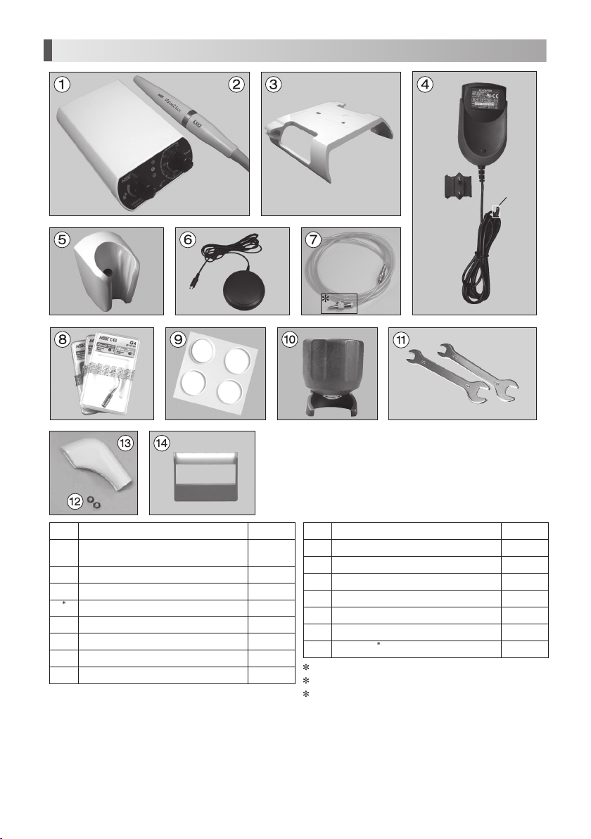
1. Component Names
DC Plug
2
No. Parts Name Quantity
Control Unit
1
(
with Handpiece Cord Unshielded 2M
Handpiece (Varios2 or Varios2 Lux)
2
Control Unit Holder
3
1
AC Adaptor (Unshielded cord 5M
4
Handpiece Holder
5
Foot Control (Unshielded 4M
6
Water Tube Set
7
Tip (G4,G6, G8
8
)
)
)
1
)
1
1
1
1
1
1
1
No. Parts Name Quantity
Rubber Pad
9
Tip Wrench
10
Spanner Wrench (5x8
11
O Ring
12
Tip Cover S (Option
13
Tip Holder (Option
14
15
Set Screw
1
Adaptor will change according to region
2
Only 120 V
3
These are not on photo above.
4
3
)
)
)
4
1
2
2
-
3
Page 6
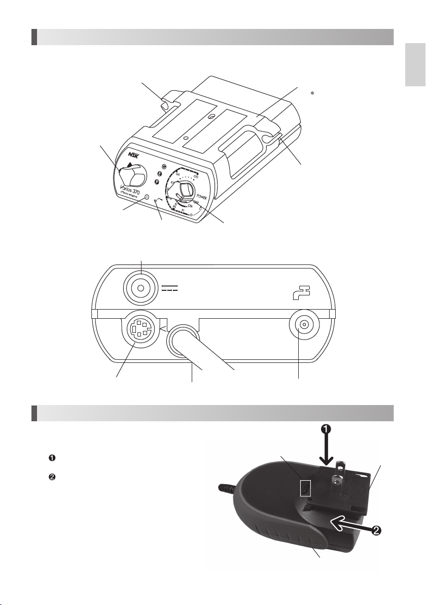
2. Name and Function of each part
Front side
Water Volume Knob
Back side
(
Control Unit With Control Unit Holder
Handpiece Cord Holder
Power Indicator
Output Indicator
DC Connector
)
Power/Volume Knob
Control Unit Holder
This Holder can move back and forth.
Handpiece Cord Holder
English
Foot Control Connector
3. Prior to Operating System
3-1 Set the AC Adaptor
Insert each plug into appropriate connector.
Insert the Plug Head into the Adapter Body as
shown in the right figure.
Slide the Plug Head on to the Adaptor Body.
To release, push the Release Button shown on the
right figure and remove the Plug Head from the
Adaptor Body.
Handpiece Cord
Water Tube Connector
Release Button
Adaptor Body
5
Plug Head
Page 7
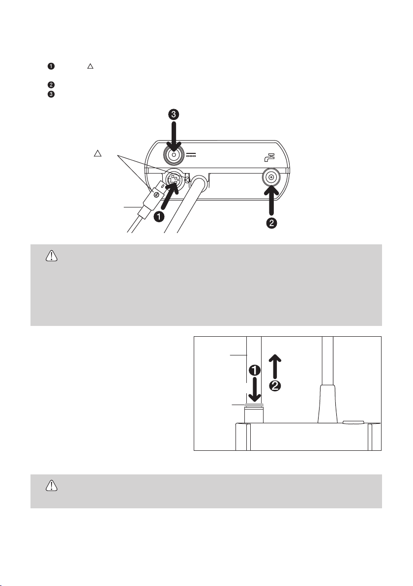
3-2 Connecting
Insert each plug into appropriate connector. (Fig.1
Align the " " Mark on the Foot Control Connector and Foot Control Plug and connect those firmly into
Foot Control Connector.
Connect Water Tube
Connect AC Adaptor into DC Connector.
Foot Control Plug
•
Insert each plug and tube firmly into the connector. If connection is incomplete, it may cause
CAUTION
a malfunction.
•
Ensure Power is OFF on the Control Unit during the AC Adaptor Connection.
•
Do not connect the cord in wall outlet before connecting DC Connector.
•
Do not pull the AC Adaptor forcibly.
•
Do not disconnect the AC Adaptor while pressing on the Foot Control.
(Non-Filter Side,
Mark
• Turn OFF the power to connect or disconnect the cords and plugs.
)
refer to Fig. 23 for detail) firmly into Water Tube Connector.
Fig.1
3-3 Disconnecting
3-3-1 DC Plug and Foot Control Plug
Simply pull out plugs from the Control Unit.
3-3-2 Water Tube (Fig.2
Depress the white ring to remove the water
tube.
•
Shut off the main valve of the water injection, and then remove the tube.
•
CAUTION
It requires the water removal before the water tube disconnection.
)
Water Tube
PULL
PUSH
White Ring
Fig.2
6
Page 8
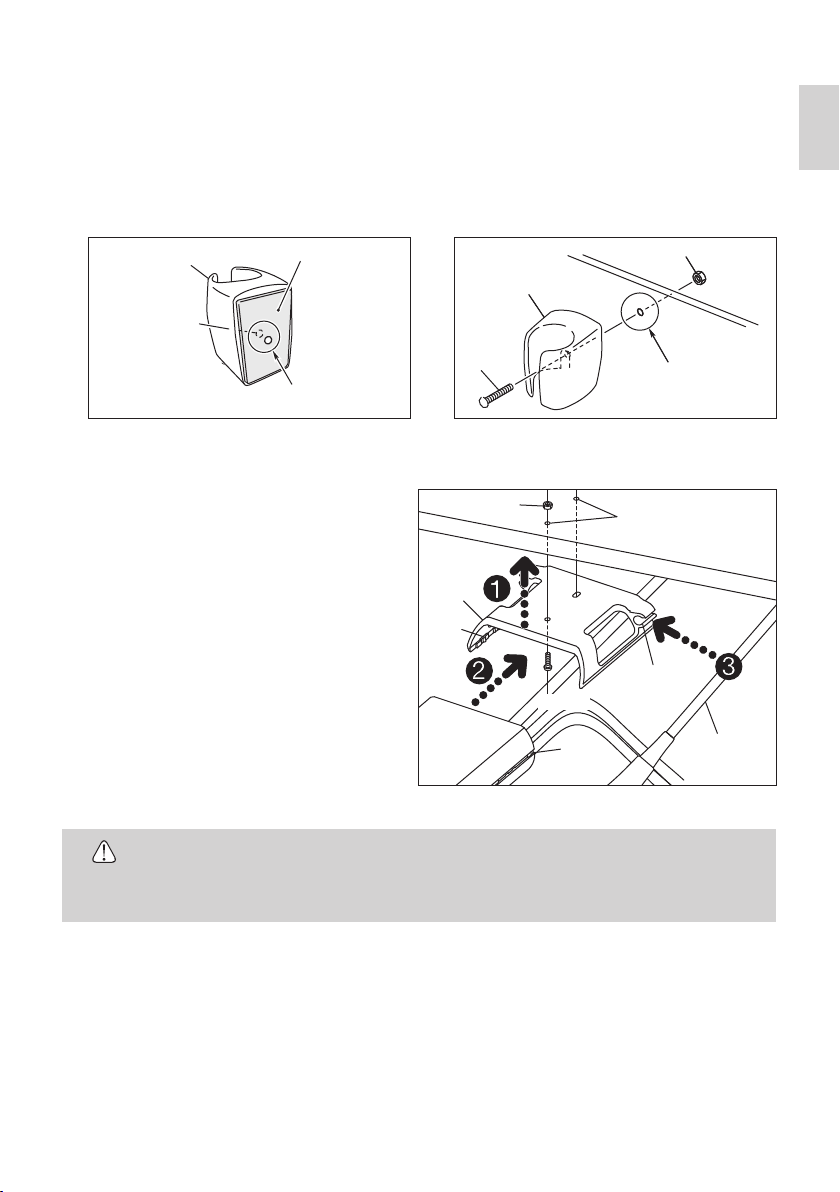
3-4 Handpiece Holder
The handpiece holder attached to the Control Unit keeps the handpiece in place when it is not in use. To mount the
Handpiece Holder on a vertical surface follow the procedures below.
1) Make a 3 mm hole in the Double-Face tape behind the screw hole in handpiece holder. (Fig. 3)
2) On the vertical surface make a 3.2~3.5 mm hole in the plate where the holder will be mounted. Align the hole with
the screw hole on the holder. Make certain the surface is clean then adhere the holder to the plate, and attach. Insert
the Set Screw through the two holes on the holder and the plate. Fasten the Set Screw with the Nut from the rear of
the plate. (Fig. 4)
Handpiece Holder
Screw hole
Double-Face Tape
Handpiece Holder
Nut
English
Set Screw
Make a hole after a screw hole
(about 3.0mm in diameter)
Fig. 3
3-5 Handpiece Cord Holder and Control Unit Holder
The Control Unit can be attached to the chair unit using
the control unit holder.
1) Make two 3.2~3.5mm holes in the mounting
surface. Insert the set screw in the hole from the
holder side and secure it with the nut.
2) Align the chaser and Slide the Control Unit into the
Control Unit Holder.
3) Tuck the Handpiece Cord into Handpiece Cord
Holder.
•
Do not pull or bend the handpiece cord forcibly as it might cause damage to the handpiece,
CAUTION
and result in improper water flow.
•
You can mount Control Unit Holder on a top surface or bottom surface.
Control Unit
Holder
Chaser
Nut
Set Screw
Chaser
Drill a hole
(3.2~3.5mm in diameter)
Drill a hole
(3.2~3.5mm in diameter)
Handpiece
Cord Holder
Handpiece
Cord
Fig. 4
Fig. 5
7
Page 9
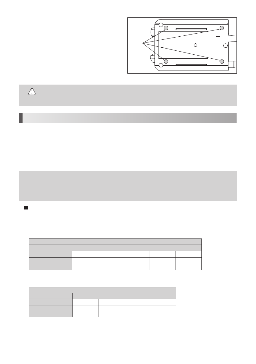
3-6 Rubber Pad
To prevent the control unit from slipping apply
rubber pads.
1) Clean bottom of the Control Unit.
2) Fit the Rubber Pad appropriate place as shown
on the Fig. 6.
•
Control Unit Holder is not necessary when rubber pads are applied.
Rubber
Pad
CAUTION
4. Sterilization before first time use
NSK Varios components are not sold sterile and should be sterilized prior to first time you use.
Autoclave sterilization is recommended.
Please note the following when sterilize components.
Follow your local directives, standards, and guidelines.
Sterilize components in a U.S. FDA-cleared sterilization pouch, complaint to ISO 11607-1.
Ensure that you only remove dry sterile goods from the sterilizer.
Store sterile goods dust-free and dry.
Fig. 6
NOTE
• NSK recommends sterilization according to ANSI/AAMI ST79 and EN 13060 (class B).
• Follow the manufacturer's instructions for use that came with your sterilizer.
• For more information about sterilization standards, refer the medical device regulations
specific to your location.
Autoclave Procedure
1) Pick a tip up from the tip case. Take handpiece out of the packing bag before sterilization.
2) Insert sterilizable components into a U.S. FDA-cleared sterilization pouch, complaint to ISO 11607-1. Seal the pouch.
3) Autoclave conditions are below:
< When sterilizing a Tip>
Steam Sterilization Cycle
Type Gravity Displacement Pre-Vacuum (Dynamic Air Removal)
Minimum Temperature
Full Cycle Time 15 minutes 10 minutes 4 minutes 3 minutes 3 minutes
Minimum Drying Time 15 minutes 30 minutes 20 minutes 30 minutes 16 minutes
* Not for use in the U.S.
<When sterilizing components except for a Tip>
Type Gravity Displacement Pre-vacuum
Minimum Temperature
Full Cycle Time 20 minutes 15 minutes 10 minutes 10 minutes
Minimum Dry Time 10 minutes 10 minutes 10 minutes 15 minutes
132°C 135°C 132°C 134°C* 135°C
Steam Sterilization Cycle
121˚C 132˚C 135˚C 135˚C
8
Page 10
• Do not exceed 138˚C during sterilization.
CAUTION
4) Keep the components in the autoclave pouch until ready to use.
5) Store in a dry and dust-free location up to the period specified by the sterilization pouch manufacturer. If sterility
cannot be confirmed, sterilize again prior to use.
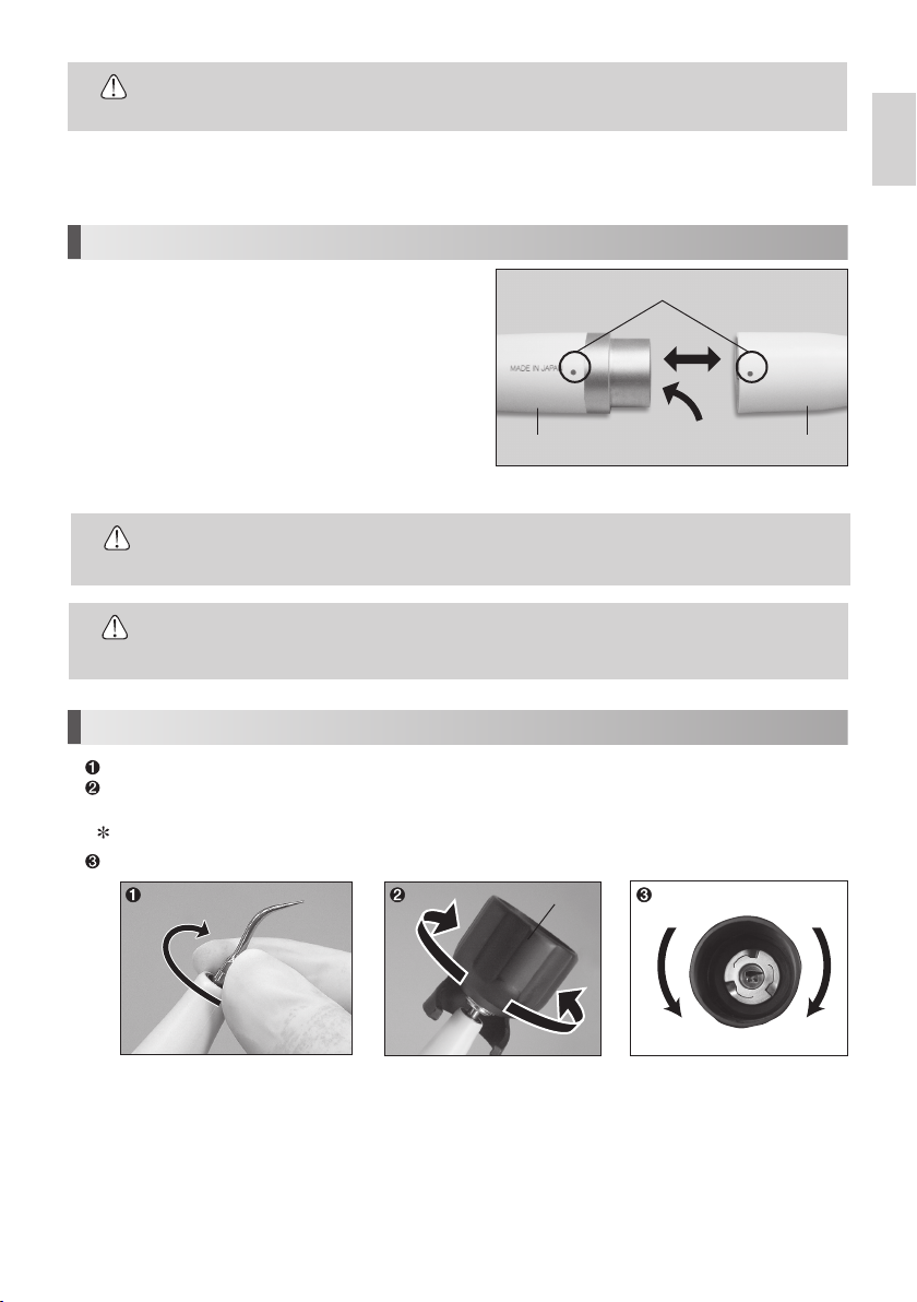
5. Mounting and Removing the Handpiece
English
Align the Dots on the Handpiece and the Handpiece Cord. Push
handpiece into connector.
To detach the handpiece, grip the Handpiece and plug of the
handpiece cord and separate in a straight motion. (Fig. 7
•
To avoid Electrical Shock Do not touch the handpiece backend electrical contacts.
)
Handpiece Handpiece Cord
Dots
Handpiece backend
WARNING
•
Always confirm that the handpiece is correctly seated and locked into place.
•
CAUTION
Do not use a Handpiece other than that supplied with this device.
6. Mounting and Removing Tip
Turn TIP lightly by hand, and install it.
Tip will insert from the bottom hole of Tip Wrench. Align the four corner of the Tip base area into the four corner of Tip
Wrench. And turn it clockwise until it clicks.
Do not touch the top part of TIP to avoid an injury.
To remove the Tip, turn it counterclockwise with the Tip Wrench.
Tip Wrench
Loosen
Fig. 7
Tighten
Tighten
Loosen
Fig. 8
9
Page 11

CAUTION
for Tip
Usage
• Check the Tip before use. (Flush, Damage, Bending or Rust)
• Do not exceed Maximum Power Level for Tip. Damage to tooth structure and Tip may result.
• Do not hit metal or prosthetic crown etc. except when removing them. Tip could break and
fall into mouth.
• Do not hit gingival, mucosa and/or skin directly. It could cause damage and/or burn injury.
• During its operation, the whole tip vibrates due to ultrasonic waves. Do not bring any part of
the tip into contact with soft tissue, gums or skin. Regardless of use of coolant water, the tip
in vibration could cause burn injury.
• The “dry tip* ” (a tip which does not require coolant water) utilizes heating to some extent for
effective treatment. During or after its operation, the whole of such tip could be overheating.
Do not bring any part of the tip into contact with soft tissue, gums or skin. Ensure that the
power setting of the Control Unit does not exceed the maximum power written on the Tip
Case label. Adjust the power from the lowest level. During use of the tip, ensure that burn
injury does not occur in or around the treatment area. Also ensure that the tip does not affect
the treatment area and oral cavity.
* E5, E6, E7, E8, G21, G22, G28
• Do not sharpen and/or bend the Tip. Tip may damage and not generate enough vibration
during scaling.
• During cutting, Tip will gradually wear away, as the Tip wears the stroke will get smaller and
decrease cutting efficiency. When level drops too far, change the Tip. (Tip Card check)
• DO ENSURE when securing Tip to use the Tip Wrench as supplied, inefficient cutting will
result.
• DO ENSURE before attaching Tip, Cleanliness of the tip screw, inefficient cutting will result.
• To avoid personal injury ENSURE Tip is removed prior to disconnecting the handpiece from
the handpiece cord.
• If you feel the Tip is not vibrating, remove it from an operative site, and press the Foot Control
again. If this does not improve the condition, Ensure the Tip is secure, turn the power off and
restart it.
• When mounting the Tip, always use groves and Tip Wrench as supplied.
• Turn water off when using Tip that does not require water.
• Tip Wrench is consumable For reliable operation replace annually.
10
Page 12
7. Operating Procedures
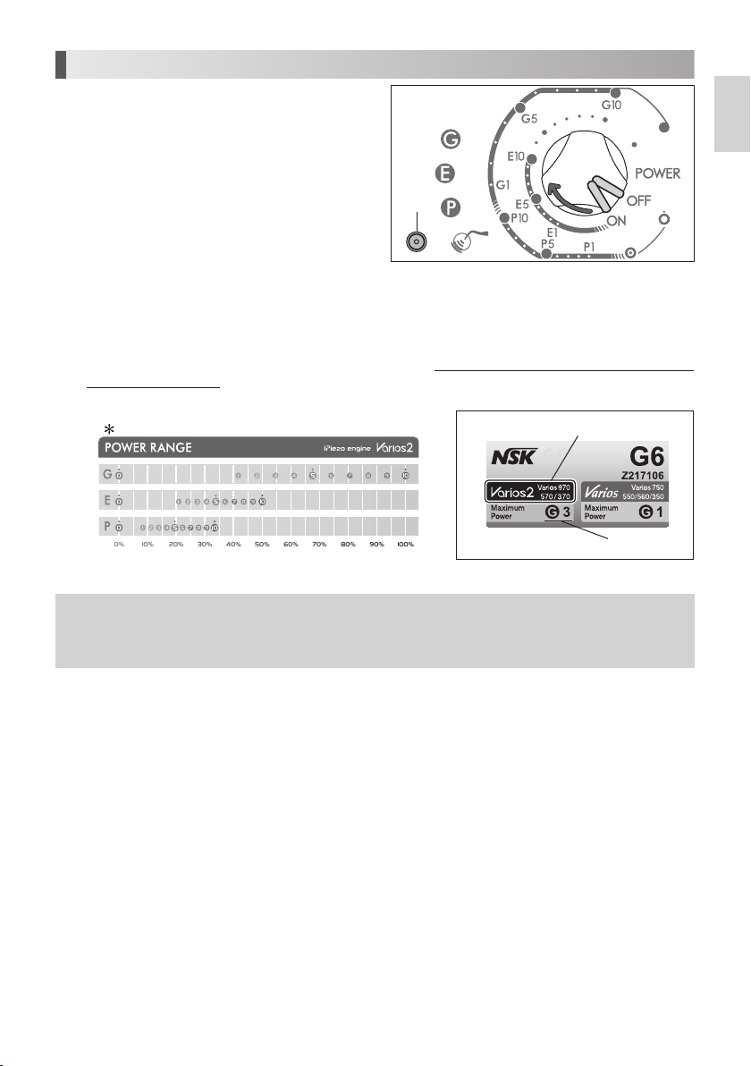
7-1 Power On (Fig. 9)
Connect the AC Cord to the wall outlet. Rotate the Power/
Volume Knob on the Control Unit. (Power indicator will
)
light.
O F F
Power
Indicator
7-2 Power Level Setting
DO ENSURE Power setting does not exceed the recommended Power Level (Tip-Power Guide or Tip case label (Fig.10)
included in the package.)
Set the power level with the Power/Volume Knob on the Front Panel. Make sure the power level is set in the appropriate
range for the attached Tip.
O N
English
Fig. 9
Power Level for each mode
NOTICE
Model
Maximum Power
Fig. 10
• Rotate the Power/Volume Knob to increase or decrease the Power Level.
• If the Power Level is set to 0 (zero), Tip will not oscillate but water comes out from the
handpiece.
11
11
Page 13

7-3 Operate Varios 370 / 370 Lux
Tip vibration will begin when the Foot Control is depressed. Also, Output Indicator will light. (For Varios2 Lux,
Handpiece LED will illuminate.
7-3-1 Water Supply Volume Adjustment
Turn the Water Adjustment Knob clockwise
gradually to increase the supply volume. (Fig. 11
During the Handpiece operation :
Possible: Power Level and Water Volume adjustment.
)
DecreaseIncrease
)
7-4 After the Treatment
Release the Foot Control and Power off the Control Unit. Close the dental unit's water valve.
How to drain the inside of the Handpiece
1) Shut off the water main valve.
2) With the Tip and Handpiece attached, turn the Power/Volume Knob to its lowest setting and then continue stepping on
the Foot Control until water stops coming from the Tip.
3) Remove the Tip and Handpiece.
Fig. 11
NOTICE
• LED of the handpiece will remain ‘On’ for approx 5 seconds after Foot Control is released.
(
Varios2 Lux
)
7-5 Protection Circuit
The Varios 370 has an internal Protection Circuit to prevent overheating. If the internal temperature of the Varios 370
becomes hot, such as when the device is used for more than 10 minutes with the power level set higher than G7, the
output of the device will be reduced automatically to G7. The device will continue to operate at this reduced level until
the internal temperature has reduced to below the protection circuit threshold. During this period, the maximum output
setting that can be used is G8 and to increase output from G7 to G8, output must first be reduced to G5 or lower, then
increased to the maximum of G8. Maximum output can be restored by turning the device off for 15 minutes or longer.
NOTICE
• During Protection Circuit function, the Control Unit can not increase the Power Level more
than 8.
12
Page 14
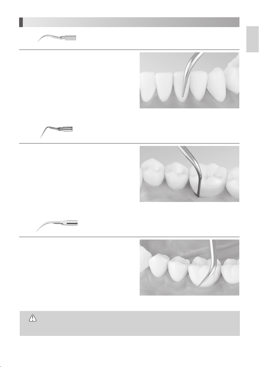
8. Provided Scaler Tips
G4
The end of the Tip is thin and for supragingival fine scaling and interdental scaling. The
round cross-section allows tooth surfaces to be finished without causing damage.
English
Apply the top of the Tip on the tooth plane and move it sideways
finely in the same way as G8 Tip. (Fig. 12
G6
Insert the top of the Tip into the periodontal pocket and move it
slowly. The top of the Tip is sharp so that it could remove tartar
on long coroner and retracted gingival. (Fig. 13
Clean periodontal pocket at low power. (Set the level less than
“Power 5” at P mode.
)
G8
)
Removal of supra and subgingival calculus. It provides easy access to interdental
spaces and narrow pockets.
)
Removal of supragingival and interdental calculus. This Tip can be used in all
quadrants and is very useful for the removal of hard calculus.
Fig. 12
Fig. 13
Apply the top of the Tip on the tooth plane and move it sideways
finely along the neck of tooth. (Fig. 14
)
• Tip is article of consumption. We recommend periodical replacement. About time of
CAUTION
replacement, check the Tip Card.
• Additional Tips and accessories are available for order in the catalog.
13
Fig. 14
Page 15

How to use the Tip Card
1) Place the neck of the Tip in the cut out.
2) Check wear of the Tip.
3) Reference the green, yellow and red line to check wear of the Tip. *Ref. Fig. 15. At NSK we recommend to replace a Tip
when the Tip meets the yellow line (wear of 1mm) to guarantee safe and effective use.
Fig. 15
• Tips are consumables. The efficiency of
CAUTION
dental scaling decreases approximately
25% when the top of the Tip wears 1
mm and approximately 50% when it
wears 2 mm. In addition, the vibration
condition changes according to the
wear, which may damage a patient’s
tooth surface. Check the Tip wear
condition with the Tip Card periodically,
and replace the Tip with a new one in
good time.
9. How to Use Tip Cover S (Option)
Grip the Tip Cover S and insert it to the Tip.
To remove, grip the Tip Cover S and the handpiece & pull.
(Fig. 17)
Green: No wear - Tip is OK
Tip replacement is not necessary.
Yellow: Wear of 1mm - Tip is showing some wear
Tip replacement is recommended.
Red: Wear of 2mm - Tip is badly worn
Tip replacement is necessary.
1mm
25%
Decrease
Efficiency
Slit
2mm
50%
Decrease
Fig. 16
Tip
CAUTION
Tip Cover
Tip-Handpiece Joint
Fig. 17
• Carefully insert the Tip into the Tip Cover S. Avoid injuring the
fingers.
• The Tip Cover S is not designed for use as a Tip changing tool.
Slit
14
Page 16

10. Holder
10-1 Handpiece Holder
While the Handpiece is not in use, put the Handpiece on the Handpiece
Holder. (Fig. 18
)
English
NOTICE
• To prevent injury, always mount Scaler Tip Cover S.
10-2 Tip Holder (Option)
The Tip Holder is Autoclavable and hold up to 5 tips at
once. To Autoclave, tilt the tips in the direction of the
arrow in Fig. 19.
11. Care and Maintenance
11-1 Cleaning of Optic Fiber (Varios2 Lux)
Wipe the debris off the end of the Optic Fibers at the
handpiece with alcohol. (Fig. 20
)
Tip
Optic Fiber End Face
Handpiece Holder
Fig. 18
Tip Holder
Fig. 19
NOTICE
• Do not use any sharp pointed tools to
clean the Optic Fiber End Face. In case
the light degradation, contact dealer.
11-2 Changing O-Ring
Handpiece Cord
An O-Ring is located in the Handpiece Cord Connector. Replace O-Ring in the groove.
(
)
Fig. 21
Optional O-Ring: Order Code D0310020080
15
Fig. 20
O-Ring
Fig. 21
Page 17

11-3 Changing Water Filter (Option)
Change the Water Filter as it may necessary.
1) Close the water valve of the
2) Mount two Spanner Wrenches (5x8) and turn those as shown in Fig. 22.
3) When the Water Filter case is separated, the Water Filter can be removed as shown in Fig. 23.
4) Replace with new
(Order Code
Chair Unit.
U387042) and reassemble the filter in the reverse order.
Varios 370/
Varios 370/
Varios 370 Lux
Varios 370 Lux
Water Filter Case
Varios 370/Varios 370 Lux
Dental Unit
Fig. 22
O-Ring
Water Filter
Dental Unit
Fig. 23
12. Periodical Maintenance Checks
In order to use the product properly and safely, perform operation checks once a year following the steps shown in “3. Prior to
Operating System”, “5. Mounting and Removing the Handpiece”, “6. Mounting and Removing Tip”, and “7. Operating Procedures”
Contact your Authorized NSK Dealer if any abnormalities are found.
13. Sterilization
• All sterilizable components of this device must be sterilized after each patient.
• The recommended method of sterilization is by autoclave sterilization.
• ONLY the Tip (except diamond coated scaler tip), Handpiece, Tip Wrench, Tip Holder and Tip Cover S can be autoclaved.
The diamond coated Scaler Tip is to be sterilized prior to first use, then disposed of as this Tip is single use only.
NOTE
• NSK recommends sterilization according to ANSI/AAMI ST79 and EN 13060 (class B).
• Follow the manufacturer's instructions for use that came with your sterilizer.
• For more information about sterilization standards, refer the medical device regulations
specific to your location.
The surface of the handpiece can be washed and disinfected with a Thermo-Disinfector prior to Sterilization.
.
Autoclave Procedure
1) Remove the Tip after use. (Refer to 6. Mounting and Removing Tip)
2) Clean all the surfaces of the components using a small tooth brush with isopropyl alcohol to remove dirt and debris then
dry thoroughly.
3) Insert sterilizable components into a U.S. FDA-cleared sterilization pouch, complaint to ISO 11607-1. Seal the pouch.
4) Autoclave conditions are below:
< When sterilizing a Tip>
Steam Sterilization Cycle
Type Gravity Displacement Pre-Vacuum (Dynamic Air Removal)
Minimum Temperature 132°C 135°C 132°C 134°C* 135°C
Full Cycle Time 15 minutes 10 minutes 4 minutes 3 minutes 3 minutes
Minimum Drying Time 15 minutes 30 minutes 20 minutes 30 minutes 16 minutes
* Not for use in the U.S.
16
Page 18

<When sterilizing components except for a Tip>
Type Gravity Displacement Pre-vacuum
Minimum Temperature 121˚C 132˚C 135˚C 135˚C
Full Cycle Time 20 minutes 15 minutes 10 minutes 10 minutes
Minimum Dry Time 10 minutes 10 minutes 10 minutes 15 minutes
•
Do not exceed 138˚C during sterilization.
Steam Sterilization Cycle
CAUTION
4) Keep the components in the autoclave pouch until ready to use.
5) Store in a dry and dust-free location up to the period specified by the sterilization pouch manufacturer. If sterility cannot be
confirmed, sterilize again prior to use.
• Do not sterilize by ultraviolet ray. The handpiece could discolor.
CAUTION
• If autoclaved with other instruments stained with chemical solution, it could strip the plating
and make the surface black.
• Do not autoclave any parts (the Control Unit, AC Adaptor, Foot Control, Handpiece Cord,
Tip Card, Tip Power Guide, O-Ring). Other than those that can be subjected to autoclave
sterilization. Perform alcohol disinfection to the Control Unit, AC Adaptor, Foot Control,
Handpiece Cord, Tip Card, Tip-Power Guide including after every patient.
• Do not wipe with, or clean or immerse in, high acid water or sterilizing solutions.
• Diamond coated Scaler Tip is for single use only. Do not sterilize and use again.
• Keep the product in suitable atmospheric pressure, temperature, humidity, ventilation, and
sunlight. The air should be free from dust, salt and sulphur.
• Do not touch the product immediately after autoclaving may cause injury.
English
17
Page 19

14. Troubleshooting
When trouble is found, please check the followings prior to consulting your dealer.
Problem Probable Cause Cause Solution
No / Poor
vibration
The Tip is bent or
broken
The Tip is flying
away
Noise from the
handpiece
The handpiece is
overheating
No / Poor water
Water leakage
Attachment of
the Control Unit
Holder is loose
With power on
and no Power
Indicator
The Tip does
not generate
vibration, in spite
of depressing
the Foot Control
—
—
—
—
The water does
not reach to the
Control Unit
Check to see if
water reaches
the Control Unit
Water is leaking
from the joint
between the
handpiece and
the cord
—
The AC Adaptor or the DC Plug is
disconnected
The Tip is not tightened firmly Tighten the Tip until the Tip Wrench clicks
Worn Tip Replace the Tip
Power has not been correctly
adjusted for the Tip
The Foot Control is disconnected Connect the Foot Control correctly
Failure of vibrator in the handpiece Contact dealer*
Failure of internal components of the
Foot Control
Power has not been properly adjusted
for the Tip
The Tip is not tightened firmly Tighten the Tip until the Tip Wrench clicks
Power has not been properly adjusted
for the Tip
The Tip is not tightened firmly Tighten the Tip until the Tip Wrench clicks
Failure of vibration in the handpiece
or the Control Unit
Power has not been properly adjusted
for the Tip
The Tip is not tightened firmly Tighten the Tip until the Tip Wrench clicks
Failure of vibration in the handpiece
or the Control Unit
—
The Water Adjustment Knob is
closed.
Disconnected water supply at low
volume range. (less than 10ml/min.)
The Water Filter is clogged Replace with new Water Filter (Refer to 11-3
O-Ring at the handpiece cord is worn
or damaged
Holder worn Contact dealer*
Correctly insert the AC Adaptor or the DC Plug
According to Power Guide or Tip case label. Do
not exceed recommendations.
Contact dealer*
According to Power Guide or Tip case label. Do
not exceed recommendations.
According to Power Guide or Tip case label. Do
not exceed recommendations.
Contact dealer*
According to Power Guide or Tip case label. Do
not exceed recommendations.
Contact dealer*
Check the water circuitry and supply to the Control
Unit. Water pressure : 0.1-0.5MPa (1-5kgf/cm
Turn the Water Volume Knob and adjust to the
appropriate volume
Adjust the Water Volume Knob and increase the
Irrigation volume
Changing Water Filter (Option) )
Replace with new O-Ring (Refer to 11-2 Changing
O-Ring Handpiece Cord)
2
)
18
Page 20

Problem Probable Cause Cause Solution
Handpiece
LED does not
illuminate.
(Varios2 Lux)
Loss of the power
output without
operation
Tip oscillates, but
Handpiece LED
turns on and off
Power output is
set 8 at G
The handpiece is not connected into
the Handpiece Cord correctly
Protection Circuit is activated
Firmly insert the handpiece into the Handpiece
Cord completely
Power output will weaken automatically while
continuous operation is over 10min at the setting
of Maximum power at G mode. Releasing the foot
from the Foot Control. Decrease the Power less
than 5, once then increase the power again. (Refer
to 7-5 Protection Circuit
* Repairs cannot be made by the customer.
15. Specification
English
)
Type
Power source
Vibration Frequency
Maximum Output
Rated Power
Lighting
Dimension
Weight
Use Environment
Store Environment
VA370 Lux/VA370
AC 100 - 240 V 47 - 63Hz
28 - 32 kHz
11 W
25VA
Varios 370 Lux: No
Varios 370 Lux: Yes
W 80 x D 115 x H 32 mm (Body without knob and cord)
0.43 kg (Except Attachment
Temperature 0 to 40 °C (The liquid must not freeze up)
30 to 75 %
Humidity
Atomospheric Pressure 700 to 1060 hPa
Temperature -10 to 60 °C
Humidity 10 to 85 %
Atomospheric Pressure 500 to 1060 hPa
)
19
Page 21

16. Spare Parts
Model Products Order code
Model Products Order code
Water Tube Set U1007080
Water Supply
Connector
Water Filter U387042
Spanner Wrench
(5x8) X 2 pcs
Tip Wrench
(CR-10)
Autoclavable up to max 135°C.
U387030
Y1001301
Z221076
Tip Holder Z221A080
Tip Cover S Z217851
O-Ring D0310020080
Set screw X 3 pcs
Rubber Pad
Double-Face Tape
(
For Handpiece Holder
)
U1007091
20002544
17. Disposing product
Consult with dealer from whom you purchased it about waste disposal.
18. Warranty
Manufacturer warrants its products to the original purchaser against defects in material and workmanship under normal
practices of installation, use and servicing. Such expendable items as O-Rings are not covered by this warranty.
20
Page 22

Symbols
TUV Rhineland of North America is a Nationally Recognized Testing Laboratory (NRTL) in the United States and is accredited by
the Standards Council of Canada to certify electro-medical products with Canadian National Standards.
Follow the waste of electric and electronic equipment (WEEE) Directive (2012/19/EC) to dispose of the product and
accessories.
English
Consult operation instructions. Manufacturer.
Class II Equipment.
This conforms to CE European Directive of “Medical equipment directive 93/42/EEC.”
Type BF applied part.
Autoclavable up to Max.135°C.
*for detail see Sterilization.
Authorised representative in
the European community.
The surface of the product can be washed and disinfected with a ThermoDisinfector prior to Sterilization.
Protected against vertically falling water
drops.
Marking on the outside of Equipment or Equipment parts that include RF transmitters or that apply RF electromagnetic energy
for diagnosis or treatment.
Single use. Do not reuse.
Rx Only Caution: U.S. Federal law restricts this device to sale by or on the order of a dentist.
Guidance and manufacturer's declaration - electromagnetic emissions
The Varios 370 / Varios 370 Lux is intended for use in the electromagnetic environment specified below. The customer or the user of the Varios 370 / Varios 370 Lux
should assure that is used in such an environment.
Emissions test Compliance Electromagnetic environment - guidance
RF emissions
CISPR11/EN55011
RF emissions
CISPR11/EN55011
Harmonic emissions
EN/IEC61000-3-2
Voltage fluctuations/flicker emissions
EN/IEC61000-3-3
Guidance and manufacturer's declaration - electromagnetic immunity
The Varios 370 / Varios 370 Lux is intended for use in the electromagnetic environment specified below. The customer or the user of the Varios 370 / Varios 370 Lux
should assure that it is used in such an environment.
Immunity test EN/IEC60601 test level Compliance level Electromagnetic environment - guidance
Electrostatic discharge (ESD)
EN/IEC61000-4-2
Electrical fast transient/burst
EN/IEC61000-4-4
Surge
EN/IEC61000-4-5
Voltage dips, short
interruptions and voltage
variations on power supply
input lines
EN/IEC61000-4-11
Power frequency (50/60Hz)
magnetic field
EN/IEC61000-4-8
NOTE: Ut is the a.c. mains voltage prior to application of the test level.
Group 1
class B
class A
Complies
±6kV contact
±8kV air
±2kV for power supply lines
±1kV for input/output
±1kV line(s) to line(s)
±2kV line(s) to earth
<5% Ut (>95% dip in Ut)
for 0.5 cycle
40% Ut (60% dip in Ut)
for 5 cycles
70% Ut (30% dip in Ut)
for 25 cycles
<5% Ut (>95% dip in Ut)
for 5 secs
3 A/m 3 A/m Power frequency magnetic fields should be at levels
The Varios 370 / Varios 370 Lux uses RF energy only for its internal function. Therefore, its RF emissions are
very low and are not likely to cause any interference in nearby electronic equipment.
The Varios 370 / Varios 370 Lux is suitable for use in all establishments, including domestic establishments
and those directly connected to the public low-voltage power supply network that supply network that
supplies buildings used for domestic purposes.
±6kV contact
±8kV air
±2kV for power supply lines
±1kV for input/output
±1kV line(s) to line(s)
±2kV line(s) to earth
<5% Ut(>95% dip in Ut)
for 0.5 cycle
40% Ut (60% dip in Ut)
for 5 cycles
70% Ut (30% dip in Ut)
for 25 cycles
<5% Ut (>95% dip in Ut)
for 5 sec
Floors should be wood, concrete or ceramic tile. If floors are
covered with synthetic material, the relative humidity should
be at least 30%.
Mains power quality should be that of a typical commercial or
hospital environment.
Mains power quality should be that of a typical commercial or
hospital environment.
Mains power quality should be that of a typical commercial
or hospital environment. If the user of the Varios 370 / Varios
370 Lux requires continued operation during power mains
interruptions, it is recommended that the Varios 370 / Varios
370 Lux be powered from an uninterruptible power supply or
a battery.
characteristic of a typical location in a typical commercial or
hospital environment.
21
Page 23

Guidance and manufacturer's declaration - electromagnetic immunity
The Varios 370 / Varios 370 Lux is intended for use in the electromagnetic environment specified below. The customer or the user of the Varios 370 / Varios 370 Lux
should assure that it is used in such an environment.
Immunity test EN/IEC60601 test level Compliance level Electromagnetic environment - guidance
Conducted RF
EN/IEC61000-4-6
Radiated RF
EN/IEC61000-4-3
NOTE 1 At 80MHz and 800MHz, the higher frequency range applies.
NOTE 2 These guidelines may not apply in all situations. Electromagnetic propagation is affected by absorption and reflection from structures, objects and people.
a Field strengths from fixed transmitters, such as base stations for radio (cellular/cordless) telephones and land mobiles radios, amateur radio, AM and FM
radio broadcast and TV broadcast cannot be predicted theoretically with accuracy. To assess the electromagnetic environment due to fixed RF transmitters, an
electromagnetic site survey should be considered. If the measured field strength in the location in which the Varios 370 / Varios 370 Lux is used exceeds the
applicable RF compliance level above, the Varios 370 / Varios 370 Lux should be observed to verity normal operation. If abnormal performance is observed,
additional measures may be necessary, such as reorienting or relocating the Varios 370 / Varios 370 Lux.
b Over the frequency range 150kHz to 80MHz, field strengths should be less than 3 V/m.
Cables and accessories Maximum length Complies with
Handpiece cord
Foot Control
AC Adaptor
3Vrms
150 kHz to 80MHz
3V/m
80MHz to 2.5 GHz
2 m
5 m
5m
3Vrms
3V/m
RF emissions, CISPR11, EN55011
Harmonic emissions,
Voltage fluctuations/ flicker emission,
Electrostatic discharge (ESD)
Electric fast transient / burst
Surge
Voltage dips, short interruptions and voltage variations on power supply input lines
Power frequency(50/60Hz) magnetic field
Conducted RF
Radiated RF
Portable and mobile RF communications equipment should be used
no closer to any part of the Varios 370 / Varios 370 Lux, including
cables, than the recommended separation distance calculated from
the equation applicable to the frequency of the transmitter.
Recommended separation distance
d = 1.2 P
d = 1.2 P 80MHz to 800MHz
d = 2.3 P 800MHz to 2.5GHz
Where P is the maximum output power rating of the transmitter in
watts (W) according to the transmitter manufacturer and d is the
recommended separation distance in meters (m).
Field strengths from fixed RF transmitters as determined by an
electromagnetic site survey, should be less than the compliance level
in each frequency range.
Interference may occur in the vicinity of equipment
marked with the following symbol:
Class B/ Group 1
EN/IEC61000-3-2
EN/IEC61000-3-3
EN/IEC61000-4-2
EN/IEC61000-4-4
EN/IEC61000-4-5
EN/IEC61000-4-11
EN/IEC61000-4-8
EN/IEC61000-4-6
EN/IEC61000-4-3
Recommended separation distances between portable and mobile RF communications equipment and the Varios 370 / Varios 370 Lux.
The Varios 370 / Varios 370 Lux is intended for use in an electromagnetic environment in which radiated RF disturbances are controlled. The customer or the user of
the Varios 370 / Varios 370 Lux can help prevent electromagnetic interference by maintaining a minimum distance between portable and mobile RF communications
equipment (transmitters) and the Varios 370 / Varios 370 Lux as recommended below, according to the maximum output power of the communications equipment.
Rated maximum output power of transmitter
For transmitters rated at a maximum output power not listed above, the recommended separation distance d in meters (m) can be estimated using the equation
applicable to the frequency of the transmitter, where P is the maximum output power rating of the transmitter in watts (W) according to the transmitter manufacturer.
NOTE 1 At 80 MHz and 800 MHz, the separation distance for the higher frequency range applies.
NOTE 2 These guidelines may not apply in all situations. Electromagnetic propagation is affected by absorption and reflection from structures, objects and people.
W
0.01 0.12 0.12 0.23
0.1 0.38 0.38 0.73
1 1.2 1.2 2.3
10 3.8 3.8 7.3
100 12 12 23
150kHz to 80MHz
d=1.2 P
Separation distance according to frequency of transmitter
m
80MHz to 800MHz
d=1.2 P
800MHz to 2.5GHz
d=2.3 P
22
Page 24

Manuel d’utilisation
Classifications de l’équipement
• Type de protection contre les chocs électriques:
– Équipement de classe II
• Degré de protection contre les chocs électriques:
– Type pièce appliquée BF:
• Méthode de stérilisation ou de désinfection recommandée par le fabricant:
– Cf. 12. Stérilisation
• Degré de protection contre l’infiltration d’eau, tel que détaillé dans l’édition actuelle de l’IEC 60529:
– Pédale de contrôle: IPX1 (protégée contre les gouttes d’eau tombant verticalement)
• Niveau de sécurité de l’appareil en présence de mélanges anesthésiants inflammables avec de l’air, de l’oxygène ou de
l’oxyde d’azote:
– ÉQUIPEMENT non adapté pour une utilisation en présence d’un mélange anesthésique inflammable avec de l’air ou de
l’oxygène ou de l’oxyde nitreux.
• Utilisation:
– Opération continue
Finalité d’utilisation
Cet appareil est destiné uniquement à être utilisé en clinique/cabinet dentaire. Cet appareil émet des ondes ultrasoniques
destinées aux traitements dentaires tels que le détartrage, les traitements du canal radiculaire, la parodontie et la préparation
des cavités.
Français
Français
Sur prescription uniquement:
à son ordonnance.
la loi fédérale américaine limite ce dispositif à la vente par un médecin autorisé ou conformément
Précautions à prendre lors de la manipulation et du fonctionnement
Lisez soigneusement cette mise en garde et n’utilisez l’appareil qu’aux fins indiquées et uniquement selon les instructions
fournies.
Les instructions de sécurité visent à éliminer tout danger potentiel pouvant causer des blessures corporelles ou
endommager l’appareil. Les instructions de sécurité sont classées comme suit, selon la gravité du risque.
•
Un danger risquant de provoquer des blessures graves ou d’endommager l’appareil si les
AVERTISSEMENT
ATTENTION
REMARQUE
instructions de sécurité ne sont pas respectées.
•
Un danger risquant de provoquer des blessures légères ou modérées, ou d’endommager
l’appareil si les instructions de sécurité ne sont pas respectées.
•
Informations générales nécessaires pour utiliser l’appareil en toute sécurité.
AVERTISSEMENT
· POUR ÉVITER LES CHOCS ÉLECTRIQUES, ne débranchez pas l’adaptateur CA avec les mains mouillées.
· POUR ÉVITER LES CHOCS ÉLECTRIQUES, veillez à ce que le boîtier de contrôle ne soit pas mouillé.
· POUR ÉVITER LES CHOCS ÉLECTRIQUES, ne touchez pas les connexions électriques de l’extrémité de la pièce à main.
· POUR ÉVITER LES CHOCS ÉLECTRIQUES, utilisez une prise électrique reliée à la terre.
· Si vous constatez une quelconque anomalie, comme des vibrations, une génération de chaleur, un bruit anormal, etc.
avant ou pendant l’utilisation de l’appareil, arrêtez immédiatement de l’utiliser.
· Cet appareil est un équipement médical électrique à compatibilité électromagnétique (CEM). Description dans la
documentation ci-jointe.
· Les équipements de communication RF mobiles et portables peuvent interférer avec l’équipement électrique médical.
N’utilisez pas d’équipement RF à proximité de l’appareil.
· Lors de l’installation du produit, veillez à prévoir un dégagement d’environ 10cm autour du boîtier de contrôle pour
faciliter l’accès à la prise et à l’adaptateur CA.
23
Page 25

· Lors de l'utilisation, vérifier la présence et le débit de l'irrigation Un débit d'irrigation insuffisant peut provoquer une brûlure
des zones traitées ainsi qu'une surchauffe de l'instrument.
· Veillez à contrôler la position de l'extrémité de l'insert ultrasonore, et déplacez-le constamment afin qu'il ne reste pas en
position statique. Maintenir l'insert en position fixe pourrait entraîner une surchauffe de la dent ou du canal radiculaire,
ainsi qu'une abrasion excessive de la dent ou du canal radiculaire.
· UTILISEZ UNIQUEMENT des inserts NSK d’origine lorsque vous utilisez le détartreur ultrasonique Varios de NSK (Varios 370
ou Varios 370 Lux). Les problèmes tels que les dommages, les pannes et les accidents relatifs à la pièce à main causés
par l’utilisation d’inserts qui ne sont pas d’origine NSK ne sont pas couverts par la garantie. Voici les pannes pouvant
survenir si vous n’utilisez pas les inserts NSK;
· Vibrations causées par l’utilisation de vis non conformes.
· Ingestion accidentelle par le patient d’inserts cassés.
· Endommagement de l’arête du filetage de la pièce à main.
· Vous devez utiliser l’insert conformément à la plage de puissance décrite dans le Guide de puissance des inserts. Si vous
ne respectez pas la plage de puissance, l’insert risque de se briser ou d’endommager le site opératoire.
· Lorsque vous utilisez le produit, veillez toujours à la sécurité du patient.
· Cet appareil est conçu pour être utilisé par des professionnels de la médecine, comme un médecin ou un dentiste.
· Vérifiez les vibrations en dehors de la cavité buccale du patient avant l’utilisation. En cas d’anomalie, arrêtez
immédiatement l’appareil et contactez votre revendeur.
· Ne pas laisser faire tomber, heurter ou exercer un choc excessif sur l'unité de commande / la pièce à main. Cela pourrait
occasionner un risque de choc électrique ou une défaillance du produit. Un choc excessif sur une pièce à main équipée
d’une source lumineuse, pourraient endommager les composants optiques, provoquer leur désolidarisation et extraction
de la pièce à main.
· Utilisez toujours l’appareil avec suffisamment d’eau pour éviter d’endommager la surface de la dent et de causer une
surchauffe de la pièce à main.
· N’effectuez pas de stérilisation utilisant des rayons ultraviolets. La pièce à main pourrait se décolorer.
· Stérilisez l’insert (à l'exception de tous les inserts diamantés), la pièce à main, le support pour inserts, le capuchon d’insert
S et la clé dynamométrique par autoclave. Essuyez le boîtier de contrôle, le support pour inserts, l’insert, l’adaptateur
CA, la pédale de contrôle, la carte insert, le guide de puissance des inserts et le cordon de la pièce à main, y compris le
couvercle, avec du coton imbibé d’alcool.
· Si des produits chimiques, des solvants ou des solutions antiseptiques tombent sur l’appareil, essuyez-les immédiatement,
sinon, l’appareil risque de se décolorer ou de se déformer.
· Ne démontez pas et ne modifiez pas la pièce à main/le boîtier de contrôle.
· Tenez l’appareil à distance des personnes portant un pacemaker.
· Tenez à l’écart de substances explosives et de matériaux inflammables. Ne pas utiliser sur des patients anesthésiés au
gaz hilarant. (Protoxyde d’azote)
· Le fait de regarder directement l’éclairage LED risque de provoquer des dommages oculaires. Ne le dirigez pas vers les
yeux du patient ou de l’opérateur.
· Cet appareil requiert des précautions particulières en ce qui concerne la compatibilité électromagnétique et doit être
installé puis mis en service conformément aux informations relatives à la CEM.
·
Compatibilité électromagnétique: L’utilisation d’ACCESSOIRES, de transducteurs et de câbles autres que ceux spécifiés
(exception faite des transducteurs et des câbles vendus par le fabricant de ce produit en tant que pièces de rechange des
composants internes) peut entraîner une augmentation des ÉMISSIONS ou une diminution de l’IMMUNITÉ de ce produit.
·
Ce produit ne doit pas être utilisé ni entreposé à proximité d’autres équipements. Si l’utilisation ou le stockage à proximité est
nécessaire ce produit doit être contrôlé pour vérifier son bon fonctionnement avec la configuration dans laquelle il sera utilisé.
· S’il reste des gouttes d’eau sur la pièce à main ou le cordon de la pièce à main après l’autoclavage, essuyez-les. Sinon,
elles risquent de produire des taches.
· Les utilisateurs sont responsables du contrôle des opérations et de l’entretien.
· N’utilisez pas de tubes d’eau d’autres sociétés. Procéder ainsi peut provoquer un dysfonctionnement.
· L’utilisateur est responsable de la décision d’utiliser ce produit sur un patient.
· N’appliquez pas une puissance excessive à l’insert. Les vibrations ultrasoniques risquent d’endommager les dents.
24
Page 26

ATTENTION
·
Pendant l’utilisation, les oscillations à haute fréquence de la pièce à main et du cordon de la pièce à main risquent d’interférer
avec l’ordinateur et un bruit de réseau local risque d’être audible pendant une utilisation à proximité d’un récepteur radio.
· Veillez à mettre le bouton d’alimentation/volume sur la position d’arrêt après l’utilisation. Retirez l’adaptateur CA en cas de
non-utilisation prolongée.
·
La surface du boîtier de contrôle peut chauffer après une utilisation prolongée. Tournez le bouton d’alimentation/volume sur
la position d’arrêt et laissez refroidir l’appareil.
· Les utilisateurs sont responsables du contrôle des opérations, de l’entretien et de l’inspection.
· Nettoyez/stérilisez l’appareil immédiatement après l’avoir utilisé. Ensuite, rangez-le. Si vous le laissez dans un état non
stérile, cela risque de causer un dysfonctionnement.
· Si vous n’avez pas utilisé l’appareil pendant une période prolongée, vérifiez son fonctionnement avant toute utilisation.
· Si vous constatez qu’un boitier de contrôle et/ou un adapteur CA est affecté d’une anomalie, débranchez immédiatement
l’adaptateur CA de la prise secteur.
· Ne tournez pas le bouton alimentation/volume aux positions de marche ou d’arrêt si cela n’est pas nécessaire.
· Aucune formation spéciale n’est requise pour utiliser cet appareil.
· Les pièces appliquées pour le patient et/ou l’opérateur sont l’insert et la pièce à main.
· Lors de l’utilisation d’une lime comme insert pour un traitement de canal radiculaire (élargissement, nettoyage, etc.), ne
l’utilisez qu’après avoir confirmé ses caractéristiques et les zones où elle peut être appliquée.
· Lors du fonctionnement de ce produit, l'utilisateur et toute autres personnes à proximité doivent porter une un masque et
de lunettes de protection.
· Avant l'utilisation, vérifiez toujours que la puissance est ajustée sur le niveau approprié.
· Lorsqu'il est en vibration, ne pas bloquer l’instrument ni le faire entrer en contact pendant une période prolongée.
· Ne pas utiliser d'inserts endommagés, courbés, corrodés ou présentant d'autres imperfections. L'insert pourrait se briser
ou vibrer aléatoirement.
· Ne pas appliquer de pression excessive sur l'extrémité de l'insert, cela pourrait provoquer sa rupture ou sa déformation.
Ne pas non plus le tordre ou l'utiliser en remplacement des outils chirurgicaux, ce qui pourrait provoquer les mêmes
dommages.
· Si l'insert se fissure ou se brise lors de l'utilisation, arrêtez immédiatement le traitement, et remplacez l'insert. Un
fonctionnement avec un insert endommagé pourrait blesser les gencives, le parodonte ainsi que d'autres tissus de la
cavité buccale.
· Le revêtement diamanté de l'insert peut se fragmenter en fonction de l'état des surfaces de la dent ou du canal
radiculaire. Si le revêtement diamanté est endommagé, l'efficacité diminue, ce qui réduit les performances opératoires.
Dans ce cas, remplacez immédiatement l'insert.
· Tous les éléments stérilisables accompagnant cet appareil sont livrés dans un état non stérile et doivent par conséquent
être stérilisés avant toute utilisation. Reportez-vous au chapitre 4: "Stérilisation avant la première utilisation"
· Les inserts diamantés sont des dispositis à "Usage unique" et ne doivent en aucun cas être réutilisés.
· U.S. La loi fédérale limite ce dispositif à la vente par ou sur l'ordre d'un médecin autorisé.
Français
* Principe de fonctionnement
Le générateur produit un signal électrique sinusoïdal à une fréquence ultrasonique ( f > 20kHz ). Ce signal est
appliqué à la céramique piézoélectrique située à l’intérieur du transducteur. Cette céramique piézoélectrique traduit
ce signal en vibrations mécaniques. Ces vibrations sont à la même fréquence ultrasonique que le signal électrique.
Les vibrations mécaniques sont transmises à l’extrémité distale du transducteur. L’insert «TIP», attaché à l’extrémité
distale du transducteur, vibre alors à une fréquence ultrasonique et permet d’atteindre l’objectif souhaité.
25
Page 27

1. Noms des composants
Prise CC
2
N° Nom des pièces Quantité
(
Boîtier de contrôle
1
pièce à main de 2M non blindé
Pièce à main (Varios2 ou Varios2 Lux)
2
Support de boîtier de contrôle
3
1
Adaptateur CA (cordon de 5M non blindé
4
Support de pièce à main
5
Pédale de contrôle (4M non blindé
6
Ensemble de tube d’eau
7
Insert (G4,G6, G8
8
avec le cordon de la
)
)
1
1
1
)
1
1
)
1
1
1
N° Nom des pièces Quantité
Patin en caoutchouc
9
Clé dynamométrique
10
Clé pour écrou (5x8
11
Joint
12
Capuchon d’insert S (Option
13
Support pour inserts (Option
14
15
Vis de pression
1
L’adaptateur est différent selon la région
2
Seulement 120 V
3
Ces éléments ne figurent pas sur les photos ci-dessus.
26
)
)
)
3
4
1
2
2
-
-
3
Page 28

2. Nom et fonction de chaque pièce
Surface avant
Support de cordon de la pièce à main
Bouton du débit d’eau
Indicateur d’alimentation
Surface arrière
(
Boîtier de contrôle
Indicateur de sortie
Connecteur secteur
avec support du boîtier de contrôle
Bouton d’alimentation/volume
)
Support de boîtier de contrôle
Ce support peut glisser vers l’avant
et l’arrière.
Support de cordon de la pièce à main
Français
Connecteur de la pédale de contrôle
Cordon de la pièce à main
3. Avant d’utiliser l’appareil
3-1 Branchement de l’adaptateur CA
Insérez chaque prise dans le connecteur approprié.
Insérez la tête de la prise dans le corps de
l’adaptateur, tel qu’indiqué sur l’illustration à
droite.
Glissez la tête de la prise sur le corps de
l’adaptateur.
Pour libérer, appuyez sur le bouton de libération
indiqué sur l’illustration à droite et retirez la tête de la
prise du corps de l’adaptateur.
27
Raccord du tube d’eau
Bouton de libération
Tête de la prise
Corps de l’adaptateur
Page 29

3-2 Connexion
Insérez chaque prise dans le connecteur approprié. (Fig.1
Alignez le repère « » sur le connecteur de la pédale de contrôle et la fiche de la pédale de contrôle, puis
branchez-les fermement dans le connecteur de la pédale de contrôle.
Connectez le tube d’eau
connecteur du tube d’eau.
Connectez l’adaptateur CA dans le connecteur CC.
Fiche de connexion de
la pédale de contrôle
•
Insérez chaque prise et chaque tube fermement dans le connecteur. Une connexion
ATTENTION
incorrecte risque de causer un dysfonctionnement.
•
Assurez-vous de la mise hors tension du boîtier de contrôle pendant la connexion de
Repère
(côté sans filtre,
référez-vous à la Fig. 23 pour plus de détails) fermement dans le
l’adaptateur CA.
•
Ne connectez pas le cordon à une prise murale avant de brancher le connecteur CC.
•
Ne forcez pas lorsque vous tirez sur l’adaptateur CA.
•
Ne débranchez pas l’adaptateur CA lorsque la pédale de contrôle est enfoncée.
•
Mettez l’appareil hors tension avant de brancher ou de débrancher les cordons et les prises.
)
Fig.1
3-3 Déconnexion
3-3-1 Prise CC et prise de la pédale de contrôle
Retirez simplement les prises du boîtier de
contrôle.
3-3-2 Tube d’eau (Fig.2
Appuyez sur l’anneau blanc pour retirer le
tube d’eau.
•
Fermez la vanne principale de l’injection d’eau, puis retirez le tube.
•
ATTENTION
L’eau doit être retirée avant le retrait du tube d’eau.
)
Tube d’eau
TRACTION
POUSSÉE
Anneau blanc
Fig. 2
28
Page 30

3-4 Support de pièce à main
Le support de pièce à main fixé au boîtier de contrôle maintient la pièce à main en place lorsque vous ne l’utilisez pas.
Pour monter le support de pièce à main sur une surface verticale, suivez les procédures ci-dessous.
1) Faites un trou de 3mm dans le ruban adhésif double face derrière l’orifice de la vis dans le support de pièce à main.
(Fig. 3)
2) Sur la surface verticale, faites un trou de 3,2 ~ 3,5mm dans la plaque où le support doit être monté. Alignez le trou
avec le trou de la vis sur le support. Veillez à ce que la surface soit propre, puis placez le support contre la plaque et
fixez. Insérez la vis de pression dans les deux trous du support et de la plaque. Serrez la vis de pression avec l’écrou
depuis l’arrière de la plaque. (Fig. 4)
Support de pièce à main
Orifice de la vis
Ruban adhésif double face
Faites un trou après l’orifice de la vis
(environ 3,0mm de diamètre)
Support de pièce à main
Vis de
pression
Écrou
Percez un trou
(3,2~3,5mm de diamètre)
Fig. 3
3-5 Support du cordon de la pièce à main et support du boîtier de contrôle
Le boîtier de contrôle peut être fixé sur l’unité de
traitement en utilisant le support du boîtier de contrôle.
1) Faites deux trous de 3,2 ~ 3,5mm dans la surface
de montage. Insérez la vis de pression dans le trou
depuis le côté du support et fixez-la avec l’écrou.
2) Alignez la rainure et faites glisser le boîtier de
contrôle dans le support du boîtier de contrôle.
3) Insérez le cordon de la pièce à main dans le support
du cordon de la pièce à main.
Support de
boîtier de
Rainure
contrôle
Écrou
Vis de pression
Percez un trou
(3,2~3,5mm de diamètre)
Support de
cordon de la
pièce à main
Français
Fig. 4
ATTENTION
Rainure
•
Ne tirez pas et ne pliez pas trop fort le cordon de la pièce à main, car cela risque
Cordon de la
pièce à main
d’endommager la pièce à main et de provoquer un mauvais débit d’eau.
•
Vous pouvez monter le support du boîtier de contrôle sur la surface supérieure et la surface
inférieure.
29
Fig. 5
Page 31

3-6 Patin en caoutchouc
Pour empêcher le boîtier de contrôle de glisser,
installez des patins en caoutchouc.
1) Nettoyez le dessous du boîtier de contrôle.
2) Installez les patins en caoutchouc aux endroits
appropriés tel qu’indiqué sur la figure 6.
•
Le support du boîtier de contrôle n’est pas nécessaire lorsque des patins en caoutchouc sont
ATTENTION
installés.
Patins en
caoutchouc
4. Stérilisation avant la première utilisation
L'insert livré n'étant pas conditionné à l'état stérile, il est impératif de le stériliser avant toute utilisation.
La stérilisation par autoclave est fortement recommandée.
Veuillez à appliquer les préconisations suivantes lors des opérations de stérilisation.
Conformez-vous aux directives, normes et recommandations locales en vigueur.
N’utilisez que des poches de stérilisation approuvées par la FDA, et qui soient conformes à la norme ISO 11607-1.
Assurez-vous que les éléments stériles sortis de l’autoclave sont parfaitement secs.
Conservez les éléments stériles dans un environnement à l’abri de la poussière et de l’humidité.
Fig. 6
REMARQUE
• NSK recommande d’effectuer la stérilisation selon les normes ANSI/AAMI ST79 et EN 13060
(classe B).
• Suivez les instructions du fabricant fournies avec votre stérilisateur.
• Pour plus d'informations sur les normes de stérilisation, reportez-vous à la réglementation
locale en vigueur relative aux appareils médicaux.
Procédure de stérilisation
1) Sélectionner et sortir un insert de la boîte, et sortir la pièce à main de son emballage.
2) Insérer les éléments à stériliser dans une poche dee stérilisation approuvées par la FDA, et qui soit conforme à la norme
ISO 11607-1. Sceller correctement la poche et vérifier- la.
3) Les paramètres de stérilisation en Autoclave figurent ci-dessous:
< Pour stériliser un insert ultrasonore >
Type
Température minimale
Complete cycle time 15 minutes 10 minutes 4 minutes 3 minutes 3 minutes
Temps de séchage minimal 15 minutes 30 minutes 20 minutes 30 minutes 16 minutes
* Non applicable aux Etats-Unis.
<Pour stériliser d’autre élément à l’exception des inserts>
Type Cycle à déplacement de gravité Cycle avec Vapeur saturée et pré-vide
Température minimale 121˚C 132˚C 135˚C 135˚C
Complete cycle time
Temps de séchage minimal
Cycle de stérilisation à la vapeur
Cycle à déplacement de gravité
132°C 135°C 132°C 134°C* 135°C
Cycle de stérilisation à la vapeur
20 minutes 15 minutes 10 minutes 10 minutes
10 minutes 10 minutes 10 minutes 15 minutes
Cycle avec Vapeur saturée et pré-vide
30
Page 32

• La température de stérilisation ne doit jamais aller au-delà de 138°C.
ATTENTION
4) Conserver les éléments stériles dans la poche de stérilisation jusqu’au moment de l’utilisation.
5) La poche de stérilisation doit être conservée dans un environnement sec et propre, jusqu'à la date de péremption
spécifiée par le fabricant de la poche, ou la date de validité du processus de stérilisation. En cas de doute, ou de
poche endommagée, changer la poche et procéder de nouveau à la stérilisation.
5. Montage et retrait de la pièce à main
Alignez les points sur la pièce à main avec le cordon de la
pièce à main. Enfoncez la pièce à main dans le connecteur.
Pour retirer la pièce à main, saisissez la pièce à main et la fiche
du cordon de la pièce à main, puis tirez-les. (Fig. 7
)
Pièce à main
Points
Arrière de la pièce à main
Cordon de la pièce à main
• Pour éviter les chocs électriques, ne touchez pas les contacts électriques de l’extrémité de la
AVERTISSEMENT
pièce à main.
• Assurez-vous toujours que la pièce à main soit bien installée et bloquée.
ATTENTION
• N’utilisez pas de pièce à main autre que celle fournie avec cet appareil.
6. Montage et retrait de l’insert
Tournez légèrement l’insert à la main et installez-le.
L’insert s’introduit depuis l’orifice du bas de la clé dynamométrique. Alignez les quatre angles de la base de l’insert dans
les quatre angles de la clé dynamométrique, puis tournez-la dans le sens des aiguilles d’une montre jusqu’à ce qu’un
déclic retentisse.
Afin d’éviter de vous blesser, ne touchez pas la partie supérieure de l’insert.
Pour retirer l’insert, tournez-le dans le sens inverse des aiguilles d’une montre avec la clé dynamométrique.
Clé dynamométrique
Desserrer
Français
Fig. 7
Serrer
Serrer
Desserrer
Fig. 8
31
Page 33

ATTENTION
à l’utilisation
de l’insert
• Vérifiez l’insert avant de l’utiliser. (Sale, endommagé, courbé ou rouillé)
• Ne dépassez pas le niveau de puissance maximale de l’insert. Vous pourriez endommager la
structure dentaire et l’insert.
• Ne touchez pas d’élément en métal ou prothétique, etc. sauf pour l’enlever. L’insert pourrait
se briser et tomber dans la bouche.
• Ne touchez pas directement les gencives, les muqueuses et/ou la peau. Cela pourrait causer
des dommages et/ou des brûlures.
• Lors de l’utilisation, la totalité de l’instrument entre en vibration en raison des ondes
ultrasoniques. De ce fait, aucune partie de l’instrument ne doit être en contact avec les tissus
mous, la gencive ou la peau. Même en présence liquide de refroidissement, tout contact de
l’instrument en vibration avec les tissues mous pourrait occasionner des brûlures.
• Un “insert dit “sec” n’a pas besoin d'eau de refroidissement, et produit un échauffement
contrôlé, nécessaire à son fonctionnement. Néanmoins, durant ou après son utilisation,
l'ensemble de l’insert pourrait surchauffer. De ce fait, veillez à ce qu’aucune partie de l’insert
n’entre au contact de tissus mous, de la gencive ou de la peau. Assurez-vous que le réglage
de la puissance de l'unité de commande ne dépasse pas la puissance maximale indiquée sur
l'étiquette d’emballage de l’insert, et démarrez l’utilisation à partir du niveau de puissance
le plus bas. Pendant l'utilisation de l’insert, assurez-vous qu’il n’y ait aucun dommage
thermique sur ou autour de la zone de traitement. Assurez-vous également l’insert n'affecte
pas la zone de traitement et la cavité buccale.
* E5, E6, E7, E8, G21, G22, G28
• N’aiguisez pas et/ou ne pliez pas l’insert. L’insert pourrait être endommagé et ne plus
générer suffisamment de vibrations pendant le détartrage.
• L’insert s’use progressivement lors de la découpe. Plus il s’use, plus sa course rétrécit et
plus il perd en efficacité de coupe. Lorsque le niveau devient trop bas, changez l’insert.
(vérification de la carte insert)
• ASSUREZ-VOUS lorsque vous fixez l’insert d’utiliser la clé dynamométrique fournie, sinon la
découpe sera insuffisante.
• ASSUREZ-VOUS avant de fixer l’insert que la vis de l’insert est propre, sinon la découpe sera
insuffisante.
• ASSUREZ-VOUS afin d’éviter toute blessure que l’insert a été retiré avant de débrancher la
pièce à main ou le cordon de la pièce à main.
• Si vous sentez que l’insert ne vibre pas, retirez-le du site opératoire et appuyez à nouveau sur
la pédale de contrôle. Si cela n’améliore pas la situation, vérifiez que l’insert soit bien fixé,
éteignez l’appareil puis rallumez-le.
• Lorsque vous montez l’insert, utilisez toujours des gants et la clé dynamométrique fournie.
• Coupez l’eau lorsque vous utilisez un insert qui ne nécessite pas d’eau.
• La clé dynamométrique est une pièce consommable. Remplacez-la annuellement pour
assurer un fonctionnement fiable.
32
Page 34

7. Procédures d’utilisation
7-1 Démarrage (Fig. 9)
Branchez le cordon CA à la prise murale. Tournez le
bouton d’alimentation/volume du boîtier de contrôle.
(
L’indicateur de puissance s’allume.
7-2 Réglage du niveau de puissance
ASSUREZ-VOUS que le réglage de la puissance ne dépasse pas le niveau de puissance recommandé (guide de
puissance des inserts ou étiquette sur le boîtier de l’insert (Fig.10) inclus dans la trousse.)
Réglez le niveau de puissance avec le bouton d’alimentation/volume sur le panneau avant. Veillez à ce que le niveau de
puissance soit réglé dans la plage adaptée à l’insert fixé.
)
O F F
Indicateur
d’alimentation
O N
Français
Fig. 9
Niveau de puissance pour chaque mode
REMARQUE
• Tourner le bouton d’alimentation/volume a pour effet d’augmenter ou de diminuer le niveau
de puissance.
• Si le niveau de puissance est de 0 (zéro), l’insert n’oscille pas mais de l’eau sort de la pièce
à main.
Modèle
Puissance maximale
Fig. 10
33
Page 35

7-3 Utilisation de Varios 370/370 Lux
L’insert commence à vibrer lorsque vous appuyez sur la pédale de contrôle. De plus, l’indicateur de sortie s’allume.
(
Pour Varios2 Lux, la lumière LED de la pièce à main s’allume.
7-3-1 Réglage du débit d’eau
Tournez progressivement le bouton de réglage
du débit d’eau dans le sens des aiguilles d’une
montre pour augmenter le débit. (Fig. 11
Pendant le fonctionnement de la pièce à main:
Possible: Réglage du niveau de puissance et du débit d’eau.
)
)
DiminuerAugmenter
7-4 Après le traitement
Relâchez la pédale de contrôle et éteignez le boîtier de contrôle. Fermez la vanne d’eau de l’unité dentaire.
Comment vider l’intérieur de la pièce à main
1) Fermez la vanne d’eau principale.
2) Avec l’insert et la pièce à main fixés, tournez le bouton d’alimentation/volume sur son réglage minimal, puis continuez
à enfoncer la pédale de contrôle jusqu’à ce que l’eau ne sorte plus de l’insert.
3) Retirez l’insert et la pièce à main.
Fig. 11
REMARQUE
• La LED de la pièce à main reste allumée pendant environ 5secondes après le relâchement
de la pédale de contrôle. (Varios2 Lux
)
7-5 Circuit de protection
Le Varios 370 dispose d’un circuit de protection interne pour empêcher les surchauffes. Si la température interne du
Varios 370 devient élevée, comme lorsque l’appareil est utilisé pendant plus de 10minutes avec un niveau de puissance
supérieur à G7, la puissance de l’appareil est automatiquement réduite à G7. L’appareil continue de fonctionner à ce
niveau réduit jusqu’à ce que la température interne redescende en dessous du seuil du circuit de protection. Pendant
cette période, le réglage de puissance maximale pouvant être utilisé est G8. Pour augmenter la puissance de G7 à G8,
celle-ci doit d’abord être réduite à G5 ou moins, puis augmentée au niveau maximal G8. La puissance maximale peut
être restaurée en éteignant l’appareil pendant 15minutes ou plus.
REMARQUE
• Lorsque la fonction du circuit de protection est activée, le boîtier de contrôle ne peut pas
augmenter le niveau de puissance à plus de 8.
34
Page 36

8. Inserts de détartrage fournis
G4
Appliquez le dessus de l’insert sur la surface de la dent et
déplacez-le latéralement et avec précision, comme pour l’insert
G8. (Fig. 12
)
L’extrémité de l’insert est fine, pour un détartrage sus-gingival et interdentaire précis.
La section transversale ronde permet d’effectuer la finition de la surface des dents
sans causer de dommages.
Français
Fig. 12
G6
Insérez le dessus de l’insert dans la poche parodontale et
déplacez-le lentement. Le dessus de l’insert est aiguisé, de
façon à pouvoir éliminer le tartre sur la longue couronne et les
gencives rétractées. (Fig. 13
Nettoyez la poche parodontale à faible puissance. (Réglez le
niveau en dessous de «Puissance 5» en mode P.
G8
Appliquez le dessus de l’insert sur la surface de la dent et
déplacez-le latéralement et avec précision le long du collet de la
dent. (Fig. 14
)
Retrait du tartre sus-gingival et sous-gingival. Il facilite l’accès aux espaces
interdentaires et aux poches étroites.
)
)
Retrait du tartre sus-gingival et interdentaire. Cet insert peut être utilisé sur chaque
quadrant et est très utile pour retirer du tartre dur.
Fig. 13
Fig. 14
ATTENTION
• L’insert est une pièce consommable. Nous recommandons de le remplacer régulièrement.
Pour savoir quand le remplacer, vérifiez avec la carte insert.
• D’autres inserts et accessoires peuvent être commandés dans le catalogue.
35
Page 37

Comment utiliser la carte insert
1) Placez le col de l’insert dans la découpe.
2) Vérifiez l’usure de l’insert.
3) Référez-vous aux lignes verte, jaune et rouge pour vérifier l’usure de l’insert. *Réf. Fig. 15. NSK vous recommande de
remplacer l’insert lorsqu’il arrive à la ligne jaune (usure de 1mm) afin de garantir une utilisation sûre et efficace.
Fig. 15
Vert: Aucune usure - l’insert est en bon état
Le remplacement de l’insert n’est pas nécessaire.
Jaune: Usure d’1mm - l’insert présente des signes
d’usure
Le remplacement de l’insert est recommandé.
Rouge: Usure de 2mm - l’insert est très usé
Le remplacement de l’insert est nécessaire.
• Les inserts sont des consommables.
ATTENTION
L’efficacité du détartrage dentaire
diminue d’environ 25% lorsque le
dessus de l’insert s’use de 1mm
et d’environ 50% lorsqu’il s’use de
2mm. De plus, les conditions de
vibration changent suite à l’usure, ce
qui risque d’endommager la surface
des dents du patient. Contrôlez
régulièrement l’état d’usure de l’insert
à l’aide de la carte insert et remplacezle au moment opportun.
9. Comment utiliser le capuchon d’insert S (en option)
Saisissez le capuchon d’insert S et introduisez-le sur l’insert.
Pour le retirer, saisissez le capuchon d’insert S et la pièce à
main, puis tirez. (Fig. 17)
1mm
Diminution
de 25 %
Fente
Efficacité
2mm
Diminution
de 50 %
Fig. 16
Insert
ATTENTION
• I
nsérez l’insert dans le capuchon d’insert S avec
précaution. Faites attention à ne pas vous blesser les
doigts.
• Le capuchon d’insert S n’est pas conçu pour être utilisé
comme un outil de remplacement d’insert.
36
Capuchon
d’insert
Joint insert-pièce à main
Fig. 17
Fente
Page 38

10. Support
10-1 Support de pièce à main
Lorsque vous n’utilisez pas la pièce à main, placez-la sur le support de
pièce à main. (Fig. 18
)
REMARQUE
• Afin d’éviter les blessures, mettez toujours en
place le capuchon d’insert de détartrage S.
10-2 Support pour inserts (Option)
Le support pour inserts peut être stérilisé par autoclavage
et accueillir jusqu’à 5 inserts en même temps. Pour
l’autoclave, inclinez les inserts dans la direction indiquée
par la flèche sur la Fig. 19.
11. Entretien
11-1
Nettoyage de la fibre optique (Varios2 Lux)
Essuyez les résidus de l’extrémité des fibres optiques de la
pièce à main avec de l’alcool. (Fig. 20
)
Insert
Extrémité de la fibre optique
Support de pièce
à main
Fig. 18
Support pour
inserts
Fig. 19
Français
REMARQUE
• N’utilisez pas d’outils pointus et
aiguisés pour nettoyer l’extrémité de la
fibre optique. Si la lumière s’assombrit,
contactez votre revendeur.
11-2 Remplacement du joint
Cordon de la pièce à main
Un joint est placé dans le connecteur du cordon de la pièce à main. Remplacez le
joint dans la rainure. (Fig. 21
Joint optionnel: Référence D0310020080
)
37
Fig. 20
Joint
Fig. 21
Page 39

11-3 Remplacement du filtre à eau (en option)
Remplacez le filtre à eau dès que nécessaire.
1) Fermez la vanne d’alimentation en eau de l’unité dentaire.
2) Montez deux clés pour écrou (5x8) et tournez-les tel qu’indiqué sur la figure 22.
3) Lorsque le logement du filtre à eau est séparé, le filtre à eau peut être retiré tel qu’indiqué sur la figure 23.
4) Remplacez avec une nouvelle pièce
(Référence
U387042) et remontez le filtre en inversant les étapes.
Varios 370/
Varios 370/
Varios 370 Lux
Varios 370 Lux
Boîtier du filtre à eau
Varios 370/Varios 370 Lux
Unité dentaire
Fig. 22
Joint
Filtre à eau
Unité dentaire
Fig. 23
12. Contrôles d’entretien périodique
Afin d’utiliser l’appareil correctement et en toute sécurité, vérifiez son fonctionnement une fois par an en suivant les étapes
indiquées en «
et «
Contactez votre revendeur NSK agréé si des anomalies sont détectées.
3. Avant d’utiliser l’appareil», «5. Montage et retrait de la pièce à main», «6. Montage et retrait de l’insert»,
7. Procédures d’utilisation».
13. Stérilisation
• Tous les éléments stériles accompagnants cet appareil doivent être stérilisé après l’utilisation sur chaque patient.
• La méthode de stérilisation préconisée après la stérilisation par autoclave.
• Seuls les inserts ultrasonores, (à l’exception des inserts diamantés), la pièce à main, la clé dynamométrique, le support
d’inserts, et le capuchon d’insert S peuvent être stérilisés. Les inserts ultrasonores diamantés doivent être stérilisés avant
utilisation, et ensuite, éliminés après usage, car ils ne sont destinés qu’à un usage unique.
REMARQUE
• NSK recommande d’effectuer la stérilisation selon les normes ANSI/AAMI ST79 et EN 13060 (classe B).
• Suivez les instructions du fabricant fournies avec votre stérilisateur.
• Pour plus d'informations sur les normes de stérilisation, reportez-vous à la réglementation
locale en vigueur relative aux appareils médicaux.
La pièce à main peut être décontaminée à l’aide d’un thermo-désinfecteur préalablement à la stérilisation.
Procédure de stérilisation
1) Retirer l’insert ultrasonore de la pièce à main après utilisation, (voir chapitre 5 -: Montage et retrait de l’insert)
2) Nettoyez les surfaces des composants autoclavables à l’aide d’une brossette imbibée d’alcool isopropylique pour retirer
la saleté et les résidus, puis les sécher soigneusement
3) Insérer les éléments à stériliser dans une poche dee stérilisation approuvées par la FDA, et qui soit conforme à la norme
ISO 11607-1. Sceller correctement la poche et vérifier- la.
4) Les paramètres de stérilisation en Autoclave figurent ci-dessous:
< Pour stériliser un insert ultrasonore >
Cycle de stérilisation à la vapeur
Type Cycle à déplacement de gravité Cycle avec Vapeur saturée et pré-vide
Température minimale
Complete cycle time
Temps de séchage minimal
* Non applicable aux Etats-Unis.
132°C 135°C 132°C 134°C* 135°C
15 minutes 10 minutes 4 minutes 3 minutes 3 minutes
15 minutes 30 minutes 20 minutes 30 minutes 16 minutes
38
Page 40

< Pour stériliser d’autre élément à l’exception des inserts >
Cycle de stérilisation à la vapeur
Type Cycle à déplacement de gravité
Température minimale
Complete cycle time 20 minutes 15 minutes 10 minutes 10 minutes
Temps de séchage minimal 10 minutes 10 minutes 10 minutes 15 minutes
•
La température de stérilisation ne doit jamais aller au-delà de 138°C.
121˚C 132˚C 135˚C 135˚C
Cycle avec Vapeur saturée
et pré-vide
ATTENTION
4) Conserver les éléments stériles dans la poche de stérilisation jusqu’au moment de l’utilisation.
5) La poche de stérilisation doit être conservée dans un environnement sec et propre, jusqu'à la date de péremption spécifiée
par le fabricant de la poche, ou la date de validité du processus de stérilisation. En cas de doute, ou de poche endommagée,
changer la poche et procéder de nouveau à la stérilisation.
• N’effectuez pas de stérilisation avec des rayons ultraviolets. Cela risque de décolorer la pièce
ATTENTION
à main.
• Un autoclavage avec d’autres instruments tachés par une solution chimique risque d’éliminer
le revêtement et de noircir la surface.
• N’autoclavez aucune pièce (boîtier de contrôle, adaptateur CA, pédale de contrôle, cordon de
la pièce à main, carte insert, guide de puissance des inserts, joint), à l’exception de celles
pouvant supporter une stérilisation par autoclave. Désinfectez à l’alcool le boîtier de contrôle,
l’adaptateur CA, la pédale de contrôle, le cordon de la pièce à main, la carte insert et le guide
de puissance des inserts après chaque patient.
• N’essuyez pas, ne nettoyez pas ou n’immergez pas avec/dans de l’eau très acide ou des
solutions de stérilisation.
• L’insert de détartrage avec revêtement diamant est un produit à usage unique. Ne le stérilisez
pas et ne le réutilisez pas.
• Le produit doit être conservé à une pression atmosphérique, une température, une humidité,
une ventilation et une lumière du soleil adéquates. L’air fourni doit être exempt de poussières,
de sel et de soufre.
• Ne touchez pas le produit immédiatement après le passage en autoclave, car vous pourriez
vous blesser.
Français
39
Page 41

14. Dépannage
En cas de problème, consultez d’abord les points suivants avant de contacter votre revendeur.
Problème Cause probable Cause Solution
Vibration nulle/
réduite
L’insert est plié
ou cassé
L’insert se
décroche
Bruit provenant
de la pièce à
main
La pièce à main
surchauffe
Pas/peu d’eau
Fuite d’eau
La fixation du
boîtier de contrôle
présente un jeu
L’appareil
est allumé et
l’indicateur de
puissance est
éteint
L’insert ne vibre
pas, même
avec la pédale
de contrôle
enfoncée
—
—
—
—
Le boîtier de
contrôle n’est
pas alimenté en
eau
Vérifiez si l’eau
atteint le boîtier
de contrôle
De l’eau fuit par
le joint entre la
pièce à main et
le cordon
—
L’adaptateur CA ou la prise CC est
débranché(e)
L’insert n’est pas fermement serré Serrez l’insert jusqu’à ce que la clé
Insert usé Remplacez l’insert
La puissance n’a pas été
correctement réglée pour l’insert
La pédale de contrôle est débranchée Branchez correctement la pédale de contrôle
Panne du vibrateur de la pièce à main
Panne des composants internes de
la pédale de contrôle
La puissance n’a pas été
correctement réglée pour l’insert
L’insert n’est pas fermement serré Serrez l’insert jusqu’à ce que la clé
La puissance n’a pas été
correctement réglée pour l’insert
L’insert n’est pas fermement serré Serrez l’insert jusqu’à ce que la clé
Panne de vibration dans la pièce à
main ou le boîtier de contrôle
La puissance n’a pas été
correctement réglée pour l’insert
L’insert n’est pas fermement serré Serrez l’insert jusqu’à ce que la clé
Panne de vibration dans la pièce à
main ou le boîtier de contrôle
—
Le bouton de réglage du débit d’eau
est fermé.
Alimentation en eau déconnectée à
faible débit. (moins de 10ml/min.)
Le filtre à eau est bouché Remplacez-le par un nouveau filtre à eau
Le joint ou le cordon de la pièce à
main sont usés ou endommagés
Support usé Contactez votre revendeur.*
Insérez correctement l’adaptateur CA ou la prise
CC
dynamométrique produise un déclic
Selon le guide de puissance ou l’étiquette
sur le boîtier de l’insert. Ne dépassez pas les
recommandations.
Contactez votre revendeur.*
Contactez votre revendeur.*
Selon le guide de puissance ou l’étiquette
sur le boîtier de l’insert. Ne dépassez pas les
recommandations.
dynamométrique produise un déclic
Selon le guide de puissance ou l’étiquette
sur le boîtier de l’insert. Ne dépassez pas les
recommandations.
dynamométrique produise un déclic
Contactez votre revendeur.*
Selon le guide de puissance ou l’étiquette
sur le boîtier de l’insert. Ne dépassez pas les
recommandations.
dynamométrique produise un déclic
Contactez votre revendeur.*
Vérifiez le circuit hydraulique et l’alimentation en
eau du boîtier de contrôle. Pression hydraulique:
0,1 - 0,5MPa (1 - 5kgf/cm²)
Tournez le bouton du débit d’eau et réglez-le sur
le débit approprié
Ajustez le bouton du débit d’eau et augmentez le
débit d’irrigation
(reportez-vous à «11-3 Remplacement du filtre à
eau (en option)»)
Remplacez avec un nouveau joint (référez-vous
à «11-2 Remplacement du joint - Cordon de la
pièce à main»)
40
Page 42

Problème Cause probable Cause Solution
La LED de la
pièce à main ne
s’allume pas.
(Varios2 Lux)
Perte de
puissance sans
utilisation
L’insert oscille
mais la LED de
la pièce à main
s’allume et
s’éteint
La sortie de
puissance est
réglée sur 8 en
mode G
La pièce à main n’est pas branchée
correctement au cordon de la pièce à
main
Le circuit de protection est activé
Insérez fermement et le plus loin possible la pièce
à main dans le cordon de la pièce à main
La sortie de puissance diminue automatiquement
si le fonctionnement en continu dépasse 10min à
la puissance maximale en mode G. Retirez le pied
de la pédale de contrôle. Diminuez la puissance à
moins de 5 une fois, puis augmentez-la à nouveau.
(
Référez-vous à 7-5 Circuit de protection
* Les réparations ne peuvent pas être effectuées par le client.
15. Caractéristiques
)
Français
Type
Source d’alimentation
Fréquence de vibration
Sortie maximale
Puissance nominale
Éclairage
Dimension
Poids
Environnement d’utilisation
Environnement de stockage
VA370 Lux/VA370
CA 100 - 240V 47 - 63Hz
28 - 32 kHz
11 W
25VA
Varios 370 Lux: Non
Varios 370 Lux: Oui
80 (L) x 115 (P) x 32 (H) mm (corps de l’appareil sans bouton ni cordon)
0,43kg (sans accessoires
Température 0 - 40°C (Le liquide ne doit pas geler)
30 - 75%
Humidité
Pression atmosphérique 700 - 1060 hPa
Température -10 - 60°C
Humidité 10 - 85%
Pression atmosphérique 500 - 1060 hPa
)
41
Page 43

16. Pièces de rechange
Modèle Produits Référence
Ensemble de tube
d’eau
Raccord de
l’alimentation
d’eau
Filtre à eau
Clé pour écrou
(5x8) X 2 pièces
Clé
dynamométrique
(CR-10)
Autoclavable jusqu’à 135°C au maximum.
U1007080
U387030
U387042
Y1001301
Z221076
Support pour
inserts
Capuchon d’insert S
Joint
Vis de pression x 3
Patin en
caoutchouc
Ruban adhésif
double face
(
Pour le support de
pièce à main
17. Mise au rebut du produit
Consultez votre revendeur pour en savoir plus sur la mise au rebut.
Modèle Produits Référence
Z221A080
Z217851
D0310020080
U1007091
20002544
)
18. Garantie
Le fabricant offre à l’acheteur d’origine une garantie de ses produits contre les défauts de matériel et de fabrication dans
des conditions normales d’installation, d’utilisation et d’entretien. Les pièces consommables comme les joints ne sont pas
couvertes par cette garantie.
42
Page 44

Symboles
TUV Rhineland of North America est un laboratoire de Test Reconnu au niveau National (Nationally Recognized Testing
Laboratory, NRTL) aux États-Unis et est accrédité par le Conseil des Normes du Canada pour certifier les produits électromédicaux conformément aux normes nationales canadiennes.
La mise au rebut du présent appareil et de ses accessoires doit se faire conformément aux directives sur la mise au rebut des
appareils électriques et électroniques (DEEE) (2012/19/EC).
Cf. Manuel d’utilisation. Fabricant.
Le présent appareil est conforme à la directive européenne CE «Directive pour les dispositifs médicaux 93/42/CEE».
Type pièce appliquée BF.
Autoclavable jusqu’à 135°C au maximum.
*Pour plus de détails, référez-vous à la rubrique
«Stérilisation».
Représentant autorisé dans
la communauté européenne.
La surface du produit peut être lavée et désinfectée avec
un désinfecteur thermique avant la stérilisation.
Marquage sur l’extérieur d’un équipement ou de pièces de l’équipement qui comprennent des émetteurs RF ou qui appliquent
l’énergie électromagnétique RF pour le diagnostic ou le traitement.
Usage unique. Ne pas réutiliser.
Sur prescription uniquement: la loi fédérale américaine limite ce dispositif à la vente par un médecin autorisé ou sur son ordonnance.
Conseils et déclaration du fabricant - émissions électromagnétiques
Le Varios 370 / Varios 370 Lux est destiné à être utilisé dans l’environnement électromagnétique spécifié ci-dessous. Le client ou l’utilisateur du Varios 370 / Varios
370 Lux doit s’assurer qu’il est utilisé dans un tel environnement.
Tests d’émission Conformité Environnement électromagnétique - conseils
Émissions RF
CISPR11/EN55011
Émissions RF
CISPR11/EN55011
Émissions harmoniques
EN/IEC61000-3-2
Les fluctuations de voltage/émissions
fluctuantes
EN/IEC61000-3-3
Conseils et déclaration du fabricant - Immunité électromagnétique
Le Varios 370 / Varios 370 Lux est destiné à être utilisé dans l’environnement électromagnétique spécifié ci-dessous. Le client ou l’utilisateur du Varios 370 / Varios
370 Lux doit s’assurer qu’il est utilisé dans un tel environnement.
Test d’immunité Niveau de test EN/IEC60601 Niveau de conformité Environnement électromagnétique - conseils
Décharge électrostatique
(ESD)
EN/IEC61000-4-2
Transit/charge électrique
rapide
EN/IEC61000-4-4
Surtension
EN/IEC61000-4-5
Chutes de tension, courtes
interruptions et variations
de voltage sur les lignes
d’alimentation
EN/IEC61000-4-11
Fréquence de la puissance
(50/60Hz)
champ magnétique
EN/IEC61000-4-8
REMARQUE: «Ut» est la tension CA principale avant l’application du niveau de test.
Groupe 1
Classe B
Classe A
Conforme
±6kV contact
±8kV air
±2kV pour les lignes
d’alimentation en énergie
±1kV pour l’entrée/sortie
±1kV circuit(s) vers circuit(s)
±2kV circuit(s) vers terre
<5% Ut (>95% de chute dans
Ut)
pour 0,5 cycles
40% Ut (60% de chute dans Ut)
pour 5 cycles
70% Ut (30% de chute dans Ut)
pour 25 cycles
<5% Ut (>95% de chute dans
Ut)
pendant 5 secondes
3A/m 3A/m Les champs magnétiques de la fréquence de puissance
Le Varios 370 / Varios 370 Lux utilise l’énergie radiofréquence uniquement pour son fonctionnement interne.
En conséquence, ses émissions RF sont très basses et ne causeront probablement pas d’interférences dans
les équipements électroniques situés à proximité.
Le Varios 370 / Varios 370 Lux peut être utilisé dans tous les établissements, dont les établissements à
usage domestique et ceux qui sont directement connectés au réseau public d’électricité basse tension qui
alimente des bâtiments utilisés à des fins domestiques.
±6kV contact
±8kV air
±2kV pour les lignes
d’alimentation en énergie
±1kV pour l’entrée/sortie
±1kV circuit(s) vers circuit(s)
±2kV circuit(s) vers terre
<5% Ut (>95% de chute dans
Ut)
pour 0,5 cycles
40% Ut (60% de chute dans Ut)
pour 5 cycles
70% Ut (30% de chute dans Ut)
pour 25 cycles
<5% Ut (>95% de chute dans
Ut)
pendant 5 secondes
Équipement de classe II.
Protégée contre les gouttes d’eau
tombant verticalement.
Les sols doivent être en bois, en béton ou en carrelage. Si
les sols sont revêtus d’un matériau synthétique, l’humidité
relative doit être au moins de 30 %.
La qualité de l’alimentation principale doit être équivalente à
celle d’un environnement commercial ou hospitalier typique.
La qualité de l’alimentation principale doit être équivalente à
celle d’un environnement commercial ou hospitalier typique.
La qualité de l’alimentation principale doit être équivalente à
celle d’un environnement commercial ou hospitalier typique.
Si l’utilisateur du Varios 370 / Varios 370 Lux nécessite un
fonctionnement continu pendant les coupures de courant, il
est recommandé d’alimenter le Varios 370 / Varios 370 Lux
depuis une alimentation électrique sans coupure ou une pile.
doivent se situer à des niveaux caractéristiques d’un site
typique se trouvant dans un environnement commercial ou
hospitalier typique.
Français
43
Page 45

Conseils et déclaration du fabricant - Immunité électromagnétique
Le Varios 370 / Varios 370 Lux est destiné à être utilisé dans l’environnement électromagnétique spécifié ci-dessous. Le client ou l’utilisateur du Varios 370 / Varios
370 Lux doit s’assurer qu’il est utilisé dans un tel environnement.
Test d’immunité Niveau de test EN/IEC60601 Niveau de conformité Environnement électromagnétique - conseils
RF conduit
EN/IEC61000-4-6
RF émis
EN/IEC61000-4-3
REMARQUE 1 A 80MHz et 800MHz, la gamme de fréquence supérieure est d’application.
REMARQUE 2 Ces directives peuvent ne pas s’appliquer dans toutes les situations. La propagation électromagnétique est influencée par l’absorption et la réflexion
des structures, des objets et des personnes.
a Les intensités de champs provenant de transmetteurs fixes, tels que des stations de base pour radiotéléphones (cellulaires/sans fil) et radios mobiles terrestres,
les radios amateur, la diffusion radio AM et FM et la diffusion TV ne peuvent pas être prédites théoriquement avec précision. Pour évaluer l’environnement
électromagnétique dû aux transmetteurs RF fixes, une étude électromagnétique du site doit être envisagée. Si l’intensité du champ mesuré à l’endroit où le Varios
370 / Varios 370 Lux est utilisé dépasse le niveau de conformité RF applicable indiqué ci-dessus, le Varios 370 / Varios 370 Lux doit être observé pour vérifier
son fonctionnement normal. Si des performances anormales sont constatées, des mesures supplémentaires peuvent être nécessaires, telles que réorienter ou
repositionner le Varios 370 / Varios 370 Lux.
b Au-delà de la gamme de fréquence de 150kHz à 80MHz, l’intensité de champ doit être inférieure à 3V/m.
Câbles et accessoires Longueur maximale Compatible avec
Cordon de la pièce à main
Pédale de contrôle
Adaptateur CA
Distances de séparation recommandées entre l’équipement de communication RF mobile et portable et le Varios 370 / Varios 370 Lux.
Le Varios 370 / Varios 370 Lux est destiné à être utilisé dans un environnement électromagnétique dans lequel les perturbations RF rayonnées sont contrôlées. Le
client ou l’utilisateur du Varios 370 / Varios 370 Lux peuvent contribuer à éviter les interférences électromagnétiques en maintenant une distance minimale entre
les équipements de communications RF portables et mobiles (transmetteurs) et le Varios 370 / Varios 370 Lux comme recommandé ci-dessous, conformément à la
puissance de sortie maximale des équipements de communications.
Puissance de sortie nominale maximale du
Pour les transmetteurs dont la puissance maximale n’est pas indiquée ci-dessus, la distance de séparation d recommandée en mètres (m) peut être estimée à l’aide
de l’équation applicable à la fréquence du transmetteur, où P est la puissance maximale du transmetteur en watts (W) selon le fabricant du transmetteur.
REMARQUE 1 A 80 MHz et 800 MHz, la distance de séparation pour la gamme de fréquence supérieure est appliquée.
REMARQUE 2 Ces directives peuvent ne pas s’appliquer dans toutes les situations. La propagation électromagnétique est influencée par l’absorption et la réflexion
des structures, des objets et des personnes.
3Vrms
150kHz à 80MHz
3V/m
80MHz à 2,5 GHz
2m
5 m
5m
transmetteur
W
0,01 0,12 0,12 0,23
0,1 0,38 0,38 0,73
1 1,2 1,2 2,3
10 3,8 3,8 7,3
100 12 12 23
3Vrms
3V/m
Émissions RF, CISPR11, EN55011
Émissions harmoniques,
Fluctuations de voltage/émission fluctuante,
Décharge électrostatique (ESD)
Transit/charge électrique rapide
Surtension
Chutes de tension, courtes interruptions et variations de voltage sur les lignes d’alimentation
Fréquence de puissance (50/60Hz) champ magnétique
RF conduit
RF émis
Distance de séparation en fonction de la fréquence du transmetteur
150kHz à 80MHz
d=1,2 P
La distance séparant les équipements de communication RF mobiles
et portables et un quelconque composant du Varios 370 /
Lux (câbles compris) ne peut pas être inférieure à la distance de
séparation recommandée et calculée à partir de l’équation applicable
pour la fréquence du transmetteur.
Distance de séparation recommandée
d = 1,2 P
d = 1,2 P 80MHz à 800MHz
d = 2,3 P 800MHz à 2,5GHz
Où P est le niveau de puissance maximal du transmetteur en watts
(W) selon le fabricant du transmetteur et d la distance de séparation
recommandée en mètres (m).
Les intensités de champ des transmetteurs RF fixes telles que
déterminées par une étude de site électromagnétique doivent
être inférieures au niveau de conformité dans chaque gamme de
fréquence.
Il se peut qu’il y ait des interférences à proximité des
équipements arborant le symbole suivant:
m
80MHz à 800MHz
d=1,2 P
800MHz à 2,5GHz
Varios
Classe B/ Groupe 1
EN/IEC61000-3-2
EN/IEC61000-3-3
EN/IEC61000-4-2
EN/IEC61000-4-4
EN/IEC61000-4-5
EN/IEC61000-4-11
EN/IEC61000-4-8
EN/IEC61000-4-6
EN/IEC61000-4-3
d=2,3 P
370
44
Page 46

2018.00.00 00
N
 Loading...