

Page 1

Micromotor for Laboratory Work
OPERATION MANUAL
Please read this Operation Manual carefully
before use, and file for future reference.
OM-E0387E 002
Page 2

OPERATION MANUAL
English
Micromotor for Laboratory Work
Page 3

Thank you very much for purchasing ULTIMATE XL.
Please read this Operation Manual carefully regarding the instructions for use, handling method,
and maintenance and inspection prior to use and store it in a place where users can review it
anytime.
Contents
English
IMPORTANT INSTRUCTIONS AND WARNING
1. Component Names
2. Set up of Control Unit
3. Operation Procedure
4. Speed limit mechanism
5. Protective Circuit for Motor
6. Memory Function
7. Error Code
8. Replacement of Fuse
9. Maintenance Mode
10. Vacuum-coupled Mode
11. Handling of Motor and Handpiece
12. Handpiece Stand
13. Handpiece Holder
14. Specification
15. Troubleshooting
16. Disposing Product
······································································································
·························································································
·····················································································
······················································································
···················································································
·············································································
····························································································
······················································································
·························································································
··················································································
··································································
····························································································
···························································································
···································································································
······························································································
··························································································
·············································
1
5
6
7
8
8
8
9
10
10
11
12
14
14
14
15
17
IMPORTANT INSTRUCTIONS AND WARNING -Electric Devices
WARNING!
When using electric tools, basic safety precautions should always be followed to reduce
the risk of fire, electrical shock and personal injury, including the following. Read all these
instructions before operating this product and save these instructions.
1
Page 4
A. GROUNDING INSTRUCTIONS
1. In the event of a malfunction or breakdown, grounding provides a path of least resistance for
electric current to reduce the risk of electric shock. This tool is equipped with an electric cord
having an equipment-grounding conductor and a grounding plug. The plug must be plugged
into a matching outlet that is properly installed and grounded in accordance with all local
codes and ordinances.
2. Do not modify the plug provided - if it will not fit the outlet, have the proper outlet installed by
a qualified electrician.
3. Improper connection of the equipment-grounding conductor can result in a risk of electric
shock. The conductor with insulation having an outer surface that is green with or without
yellow stripes is the equipment-grounding conductor. If repair or replacement of the electric
cord or plug is necessary, do not connect the equipment grounding conductor to a live
terminal.
4. Check with a qualified electrician or service personnel if the grounding instructions are not
completely understood, or if in doubt as to whether the tool is properly grounded.
5. Use only 3-wire extension cords that have 3-prong grounding plugs and 3-pole receptacles
that accept the tool's plug.
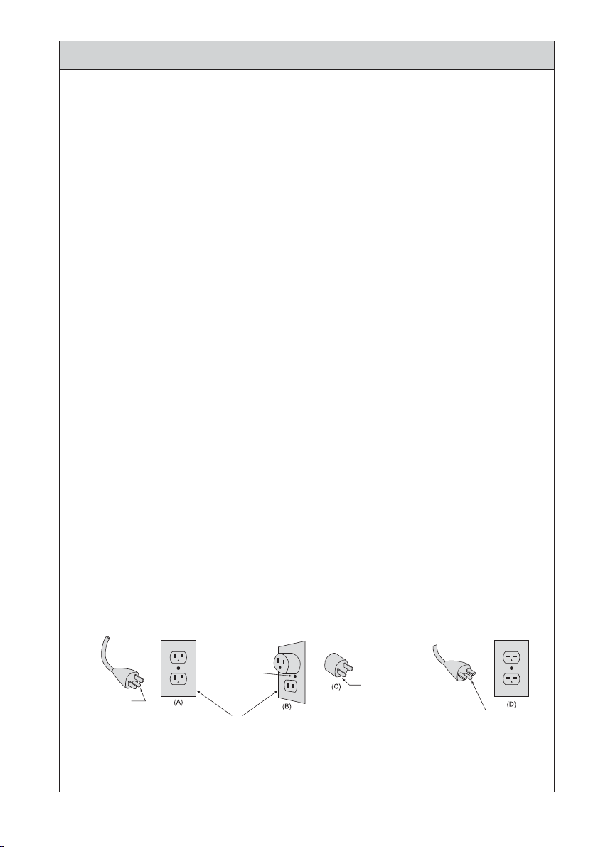
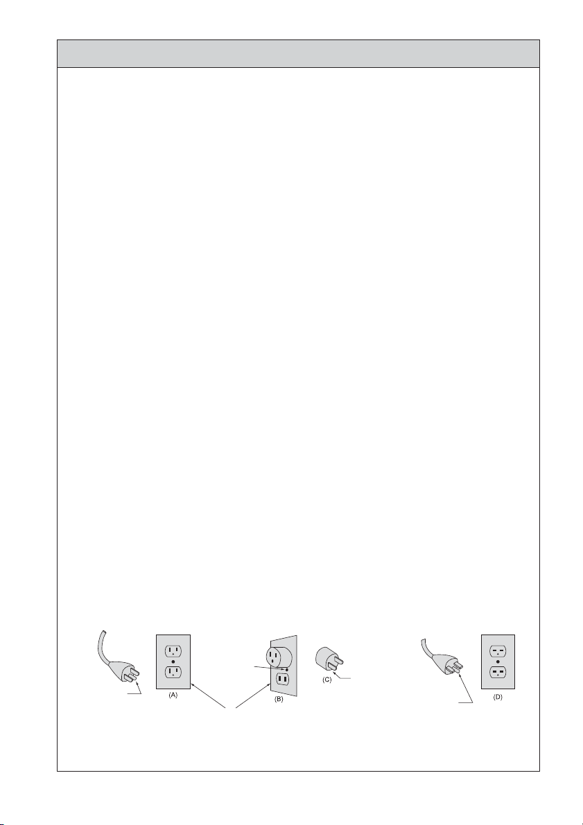
6. This tool is intended for use on a circuit that has an outlet that looks like the one illustrated in
Sketch A in Figure (below) (120V). The tool has a grounding plug that looks like the plug
illustrated in Sketch A in Figure (below). A temporary adapter, which looks like the adapter
illustrated in Sketches B and C, may be used to connect this plug to a 2-pole receptacle as
shown in Sketch B if a properly grounded outlet is not available. The temporary adapter
should be used only until a properly grounded outlet can be installed by a qualified
electrician. The green-colored rigid ear, lug, and the like, extending from the adapter must be
connected to a permanent ground such as a properly grounded outlet box.
GROUNDING
PIN
Grounding Method
METAL SCREW
COVER OF GRIUNDING
OUTLET BOX
ADAPTER
GROUNDING MEANS
GROUNDING PIN
2
Page 5
7. USE PROPER EXTENSION CORD. Make sure your extension cord is in good condition.
When using an extension cord, be sure to use one heavy enough to carry the current your
product will draw. An undersized cord will cause a drop in line voltage resulting in loss of
power and overheating. Table (below) shows the correct size to use depending on cord
length and nameplate ampere rating. If in doubt, use the next heavier gauge. The smaller the
gauge number, the heavier the cord.
8. Install equipment so that the power supply cord can be pulled out without hindrance in event
of emergency. Do not place anything within 10 centimeters around the unit.
Minimum gauge for cord
Total Length of cord
#16
#16
#16
#12
#16
#14
#14
Not Recommended
#14
#12
#12
More Than
0
6
10
12
Not More Than
6
10
12
16
Volts
7.5m (25ft.) 15m (50ft.) 30m (100ft.) 45m (150ft.)
120V
15m (50ft.) 30m (100ft.) 60m (200ft.) 90m (300ft.)Ampere Rating
240V
Code Number
#18
#18
#16
#14
B. OTHER WARNING INSTRUCTIONS
1. For your own safety read instruction manual before operating tool.
2. Wear eye protection.
3. Replace cracked wheel immediately.
4. Always use guards and eye shields.
5. Do not over tighten wheel nut.
6. Use only flanges furnished with the grinder.
7. REMOVE ADJUSTING KEYS AND WRENCHES. From habit of checking to see that keys and
adjusting wrenches are removed from tool before turning it on.
8. KEEP WORK AREA CLEAN. Cluttered areas and benches invite accidents.
9. DON'T USE IN DANGEROUS ENVIRONMENT. Don't use power tools in damp or wet
locations, or expose them to rain. Keep work area well lighted.
10. Risk of injury due accidental starting. Do not use in an area where children may be present.
11. DON'T FORCE TOOL. It will do the job better and safer at the rate for which it was designed.
12. USE RIGHT TOOL. Don't force tool or attachment to do a job for which it was not designed.
13. WEAR PROPER APPAREL. Do not wear loose clothing, gloves, neckties, rings, bracelets, or
other jewelry that might get caught in moving parts. Nonslip footwear is recommended. Wear
protective hair covering to contain long hair.
14. ALWAYS USE SAFETY GLASSES. Everyday eyeglasses only have impact resistant lenses,
they are NOT safety glasses. Also use face or dust mask if cutting operation is dusty.
15. SECURE WORK. Use clamps or a vise to hold work when practical. It's safer than using your
hand and it frees both hands to operate tool.
16. MAINTAIN TOOLS WITH CARE. Keep tools sharp and clean for best performance and to
reduce the risk of injury to persons. Follow instructions for lubricating and changing
accessories.
English
3
Page 6

17. DISCONNECT TOOLS before servicing; when changing accessories, such as blades, bits,
cutters, and like.
18. REDUCE THE RISK OF UNINTENTIONAL STARTING. Make sure switch is in off position
before plugging in.
19. USE RECOMMENDED ACCESSORIES. Consult the owner's manual for recommended
accessories. The use of improper accessories may cause risk of injury to persons.
20. NEVER LEAVE TOOL RUNNING UNATTENDED. TURN POWER OFF. Don't leave tool until it
comes to a complete stop.
21. For recommended operating speed for various applications, please follow the instructions of
bur manufacturers.
22. The system functions normally in the environment where the temperature is at 0-40°C,
humidity at 10-85% RH and no moisture condensation in the Unit. Use at outside of these
limits may cause malfunction.
23. Store the system in the place where the temperature is at -10-60°C, humidity at 10-85% RH,
atmospheric pressure at 500-1060hPa, and the system is not subject to air with dust, sulfur,
or salinity.
24. Severe shock – Eg. Dropping Control Unit, or the Micromoto – may cause damage.
25. Do not turn the bur lock ring while the handpiece is rotating.
26. Do not rotate the motor when the bur lock ring is at OPEN position, or a bur is not mounted
in the chuck. It may cause the motor/handpiece disconnection or sudden heat generation.
27. Activation of Circuit Breaker means too much load is applied to the motor beyond the
capacity the motor takes. This circuit breaker is designed to protect the motor, but it is
desired to perform the grinding work without activating the circuit breaker.
28. Care should be taken not to drop micromotor handpiece on floor or hard work surface in
order to avoid damage caused by impact shock.
29. Do not disassemble or alter the product by yourself.
30. Be careful not to be injured by the grinder or bur.
31. Be sure to replace fuse with the correct type and rating.
C. Important Instructions and Warning on ULTIMATE XL.
1. No lubrication is required to either motor or handpiece because ball bearings impregnated
with grease in both motor and handpiece.
2. Only use with original power supply cord. In case of damage, contact NSK / Nakanishi
servicing center.
3. Equipment to be sent back to manufacturer for servicing / repair.
4
Page 7
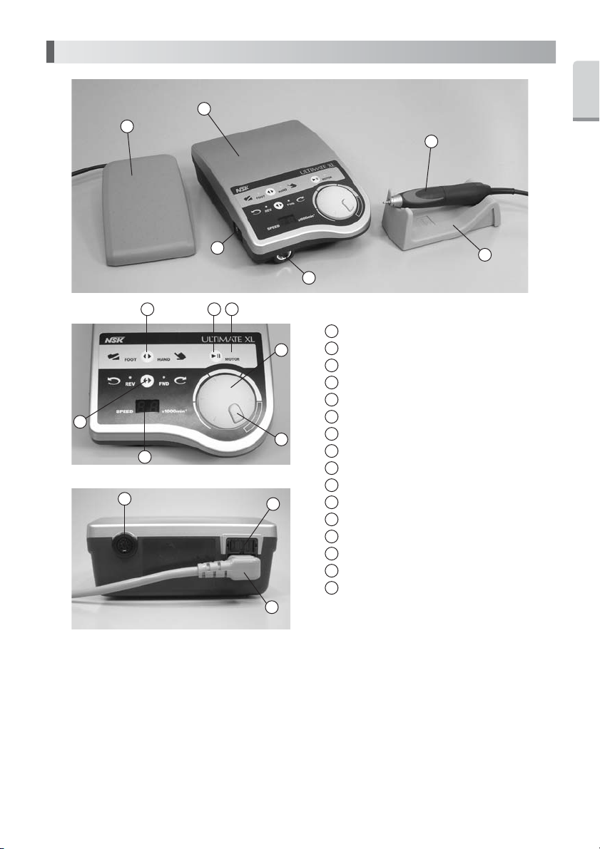
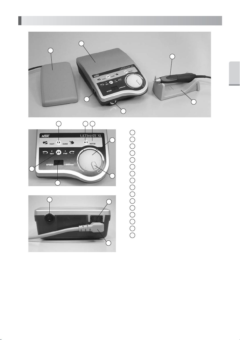
1. Component Names
1
3
2
4
5
8 9
7
11
14
10
15
16
12
13
1
Control Unit
2
Motor Handpiece
3
Foot Pedal (FC-64)
4
Power Switch
5
Motor Connector
6
Handpiece Stand
7
Forward/Reverse Selector Switch
8
Hand/Foot Selector Switch
9
Motor Switch
10
Motor LED
11
Indicator
12
Speed Control Knob
13
Speed Limit Release Button
14
Foot Pedal Connector
15
Fuse Box
16
Power supply cord
6
English
5
Page 8
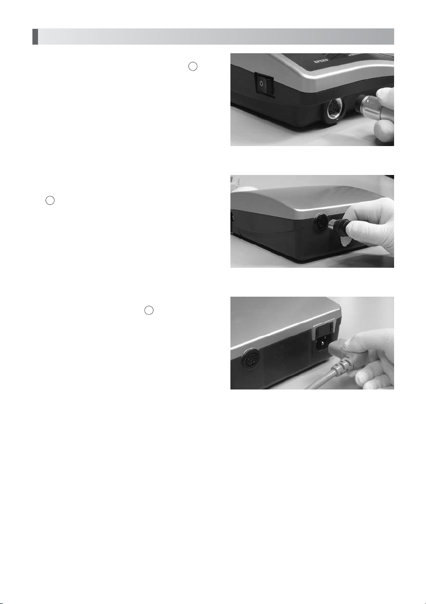
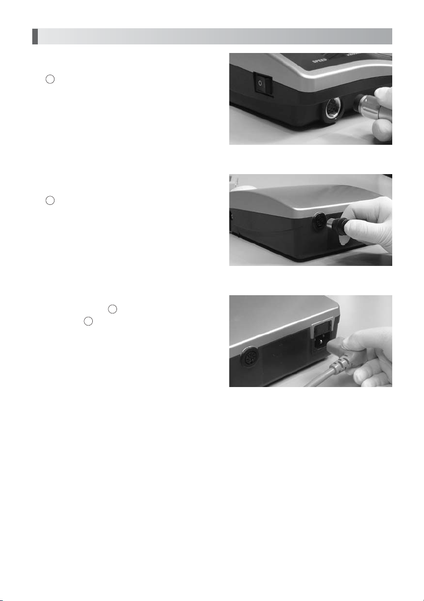
2. Set up of Control Unit
1. Mounting of Motor
Insert the motor cord plug locator into Motor
Connector aligning it with the groove of the
connector, and tighten the motor cord plug nut
to fix. (Fig. 1)
2. Mounting of Foot Pedal
Insert the Foot Pedal cord plug locator into
14
Foot Pedal Connector aligning it with the
groove of the connector. (Fig. 2)
3. Connecting of Power Cord
Securely insert the plug of Power Cord into
connector at the back of the unit aligning it with
the configuration. (Fig. 3)
16
5
Fig.1
Fig.2
Fig.3
6
Page 9

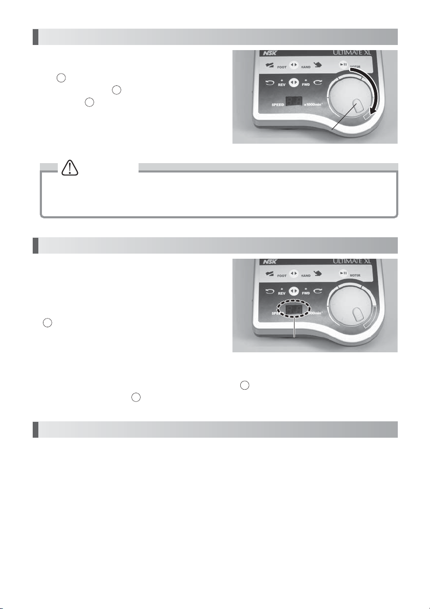
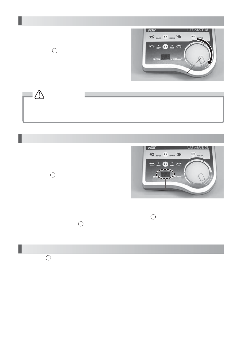
3. Operation Procedure
16
1. Connect Power Cord to a wall outlet.
2. Make sure that Speed Control Knob is at the lowest speed position.
3. Turn Power Switch ON (Green Power Lamp will light). The preset rotation speed will
4. Select the rotation direction with Forward/Reverse Selector Switch. Each time this switch
5. Select the control method with Hand/Foot Selector Switch. Each time this switch is
Operation - 1
4
appear on the Indicator.
is pressed, the direction changes between FORWARD and REVERSE.
pressed, the method changes between the HAND and FOOT.
HAND Operation
6. Select HAND with Hand/Foot Selector Switch.
7. Preset the rotation speed with Speed Control Knob with checking the speed on the
Speed Display.
8. Press Motor Switch, and the motor will run.
9. To stop the motor, press Motor Switch again.
Operation - 2
Operation by Foot Pedal
6. Select FOOT with Hand/Foot Selector Switch.
7. Preset the maximum rotation speed with Speed Control Knob with checking the speed
on the Speed Display.
8. Depress Foot Pedal, and the motor will run. The rotation speed can be variably
controlled within the preset maximum rotation speed range according to the amount of
depressing Foot Pedal.
Auto speed mechanism
To Fix the speed within the rotation speed range set by the volume, press Motor Switch
while the motor is running at the desired speed. The display lamp will flash and the rotation
speed can be maintained even if Foot Pedal is released. To cancel it, press Motor
Switch again or depress Foot Pedal again.
12
7
8
8
12
9
9
8
12
3
3
9
3
3
9
English
7
Page 10
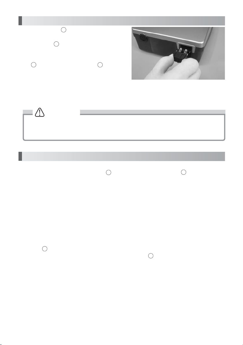
Speed Limit Release Button
Indicator
4. Speed limit mechanism
For the use of a small-diameter round bur or
fisher bur at 40,000min
13
the Speed Limit Release Button, which is
equipped with the Speed Control Knob, and
turning the Speed Control Knob allows a
12
setting of up to 50,000min
-1
(rpm) or more, pressing
12
-1
(rpm). (Fig.4)
Speed Limit Release Button
Speed Limit Release Button
CAUTION
Use of 40,000min-1(rpm) or more is allowable only when the bur manufacturer or dealer
specifies that the bur's acceptable rotation speed is 40,000 min
use of more than the acceptable rotation speed is made, the bur may be broken.
-1
(rpm) or more. If the
5. Protective Circuit for Motor
When the motor is operated with a load
exceeding the limit or the handpiece is in an
unrotational condition, the circuit to protect the
motor and unit works to stop the power supply
to the motor, an error code appears on
11
Indicator. (Fig.5)
Fig.4
Indicator
Indicator
Fig.5
How to reset the protective circuit
During manual operation, it can be reset by pressing Motor Switch again. During operation
by Foot Pedal, depress Foot Pedal back to stop, and the protective circuit will be reset.
3
9
6. Memory Function
When the Power Switch is turned on, the rotation direction and HAND/FOOT selections made
when the main switch was last turned off are restored. Special attention should be given to the
rotation direction.
8
Page 11

7. Error Code
When the motor is stopped due to some trouble such as a failure, overload, wire breakage or
misuse, Speed Display displays the error code for checking the status of the unit and
understanding the cause of the trouble easily.
Error code
E0
E1
E2
E3
E4
E5
E6
E8
E9
EF
For countermeasures against error displays, see the section on 15.Troubleshooting.
Self-check error
Overcurrent detection error
(Hard)
Overvoltage detection error
Motor sensor error
Unit overheat error
PAM circuit error
Rotor lock error
Overvoltage detection error
(Soft)
ITRIP error
Foot pedal error
Description
• Abnormal internal memory
• Broken internal memory
• Long-time use at a high load (overcorrect)
• Shorted cord (power line)
• Shorted motor winding
• Shorted cord (power line),damaged circuit
• Broken internal circuit
• Faulty sensor (Hall IC) in the motor
• Disconnected motor cord
• Severed cord (signal line)
• Open chuck
• Faulty handpiece
• Temperature rise in the unit due to longtime
use at a high load
• Unit placed under high temperature
• Abnormal voltage generated in start / stop
circuit
• Faulty start / stop circuit from PAM (L Slide)
• Open chuck
• Faulty handpiece
• Motor Faulty
• Faulty sensor (Hall IC) in the motor
• Severed cord (signal, power line)
• Long-time use at a high load (overcorrect)
• Shorted cord (power line)
• Shortstop of the motor winding
Faulty motor and circuit
• Faulty Foot Pedal or Shorted Foot Pedal cord
• Broken internal circuit
Cause
English
9
Page 12
8. Replacement of Fuse
Fuse is located in Fuse Box. Release ratchet
clamp located on the right-and-left top and
bottom of the Fuse Box and pull it out to
change the fuse. (Fig. 6)
When the fuse come down, Insert new fuses into
15
the Fuse Box and then push the Fuse Box
into the original position until hearing a sound
click.(Fig.6)
- Fuse: Order Code (120V) : 1202225010 (T2.5AH 250V)
- Fuse: Order Code (230V) : 1202216010 (T1.6AH 250V)
15
15
15
CAUTION
Fuse is burned out when a short circuit occurs or when over-voltage is flowed into the
primary current source. If the cause is uncertain, return the product to an authorized
NSK's service shop for inspection.
9. Maintenance Mode
The unit is provided with a maintenance mode to check the function of the switches, display,
Foot Pedal, motor, etc. While pressing Hand/Foot Selector Switch and Motor Switch at
the same time, turn on the Power Switch and keep pressing the button until beeps are made
(for about 2 seconds). At this time, turning the volume from the minimum position in order
displays "oP", "dP", "HL", "Pd" and "in", allowing the following checks. To release Maintenance
Mode, turn Power Switch off and switch on again.
8
(1) "oP": Switch check (operation check)
Press the switches on the panel, and the right and/or left lamps will light to check to see if
the switches operate normally.
(2) "dP": Display check
7
Press Forward/Reverse Selector Switch, and the lamps will light one by one to check to
see if they operate normally. To cancel this check, press Forward/Reverse Selector Switch
again.
7
9
Fig.6
10
Page 13
(3)
"HL": Motor signal check (Hall IC check)
7
Press Forward/Reverse Selector Switch, and Indicator will indicate one or two
horizontal lines. Turn the motor slowly by hand, and this display will change to one line, two
lines, one line, two lines, smoothly from the top to bottom or from the bottom to top. If any
one of the three lines does not light, the sensor (Hall IC) in the motor is faulty or the cord is
severed, therefore repair is needed. To cancel this check, press Forward/Reverse Selector
Switch again.
Eg.
2 3 4 A b C d C b A 4 3 2
11
7
(4) "Pd": Foot Pedal check
Press Forward/Reverse Selector Switch, and Indicator will change. During normal time,
7
Indicator changes in hexadecimals ( 0~9, A~F ) according to the amount of depressing
Foot Pedal . Also, depressing the pedal slightly lights Reset Lamp, and depressing it fully
3
extinguishes the lamp. If Indicator does not change smoothly or Reset Lamp does not
light properly, Foot Pedal may be faulty. To cancel this check, press Forward/Reverse
Selector Switch again.
3
11
11
7
(5) "in": Initializing function
Press Forward/Reverse Selector Switch, and beeps will be made and rotation direction,
7
HAND/FOOT and other settings will return to the factory set condition.
Rotation direction: FWD (forward)
HAND/FOOT: HAND
Vacuum-coupled mode: OFF
English
10. Vacuum-coupled Mode
On some dental tables with vacuum dust collector, the motor may be used while being coupled
with a dust collector. When such a dust collector * is used, power consumption of ULTIMATE
XL can be regulated so that the vacuum-coupled function can work. If you need coupling with
a vacuum dust collector, select the mode as follows:
How to select the mode
While pressing Forward/Reverse Selector Switch, turn on Power Switch, and the mode
can be selected. A long beep indicates vacuum-coupled mode and 2 short beeps indicate
non-coupled (energy-saving) mode.
* Each time the switch selection is made, the mode changes between vacuum-coupled mode
and non-coupled mode.
* A currently known dust collector is KAVO EWL-560.
7
11
4
Page 14
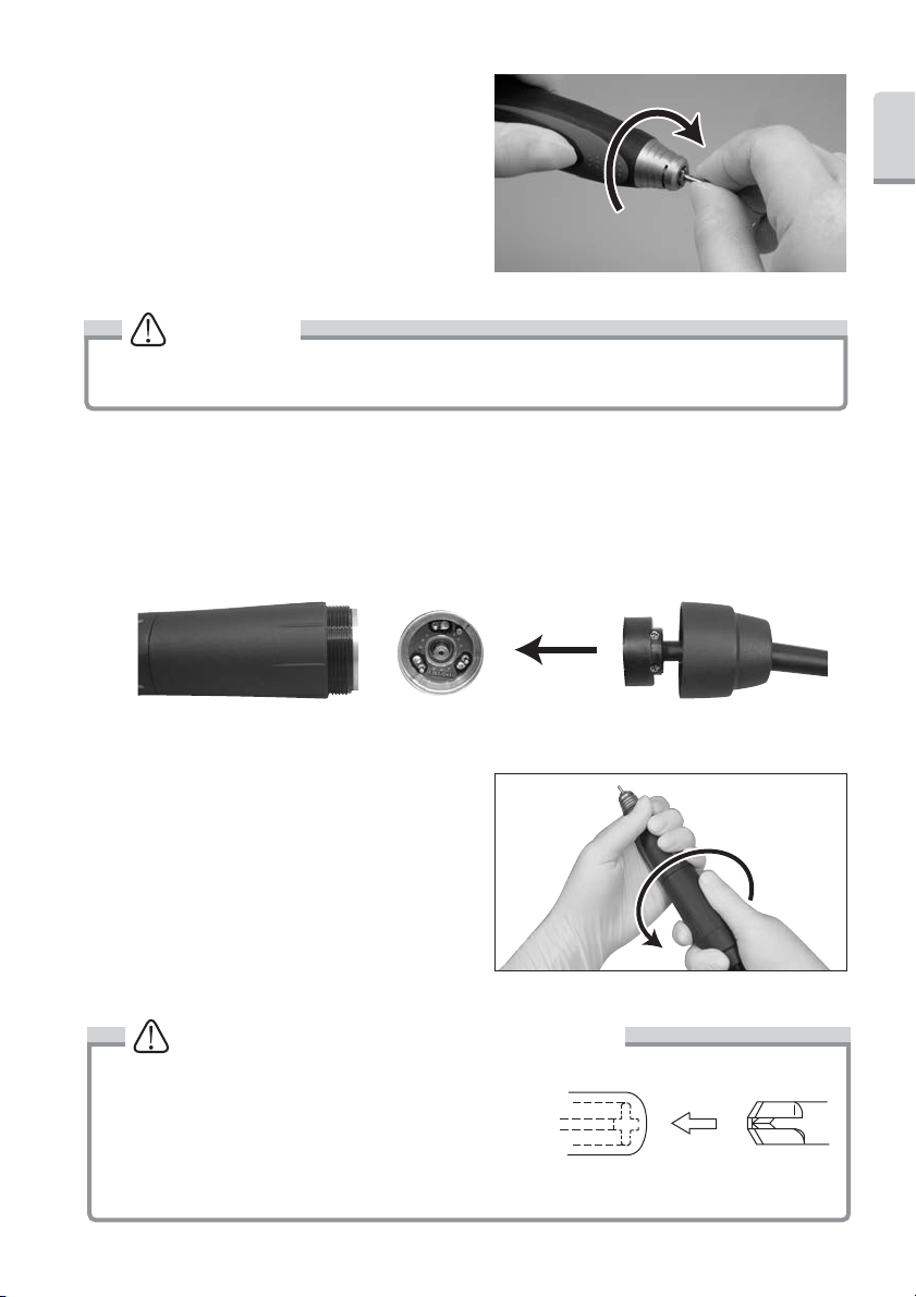
11. Handling of Motor and Handpiece
Loosen
Loosen
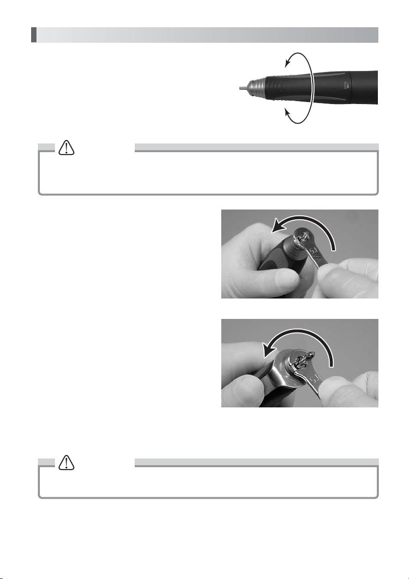
(1) Insertion or Removal of Bur
The chuck is opened by turning the Bur Lock Ring
to an open position. The chuck is loosened and the
bur can be removed. By turning the ring in the
LOCK direction, the chuck is closed and the bur
can be mounted. At this time, turn the ring until it
clicks. (Fig.7)
LOCK
OPEN
CAUTION
• Do not turn the Ring during rotation.
• Do not turn a motor, when it has not attached bur or the Ring Open position. It may be
reasons for the failure or overheating of the handpiece.
(2)
Cleaning and Replacement of Chuck
(1) Removal of Chuck
To remove the chuck, open the ring and turn
the chuck counterclockwise with the provided
spanner wrench. (Fig.8)
* If a bur having a large diameter of a cutting
part is used under a high torque, the chuck
may rotate in the close direction and the bur
may be stuck and cannot be removed. In
this case, align the nose's slit and spindle's
spanner position (flat part), and apply an L
spanner to fix the spindle. Open the ring and
turn the chuck counterclockwise with the
provided spanner wrench to remove it.
(Fig. 9)
(2) Cleaning of Chuck
Remove and clean the chuck as frequently as possible in the ultrasonic cleaner. Clean at
least once a week.
Loosen
Loosen
Loosen
Loosen
Fig.7
Fig.8
Fig.9
CAUTION
Neglecting to clean the chuck for a long time is very dangerous because wax, gypsum,
etc., accumulate in the chuck and the bur is caught insecurely, causing runout.
12
Page 15
(3) Insertion of Chuck
Turn until finger-tight
Thinly apply oil before insertion. Open the ring,
insert the dummy bur or the bur in use into
the chuck, and turn the chuck clockwise by
hand until it stops. Then, lock the ring, and
the chuck could hold the bur securely.
(Fig. 10)
Turn until finger-tight
Turn until finger-tight
CAUTION
Before using the handpiece, make sure to pull the rotating instrument (bur, etc.) to check
that it is securely mounted.
3. Disconnecting and Connecting of Motor Cord to Motor
Remove the cord nut at the rear end of the motor, and the motor cord connector can be
pulled out. For connection, align the connector pin and the hole in the motor cord connector,
and insert the connector straight until it stops. Then, tighten the cord nut.
* When inserting the connector, do not turn or twist it.
English
Fig.10
4.
Disconnecting Handpiece from Motor
The handpiece and motor are screwed at the
midpoint. Firmly grasp the motor outer case
and the handpiece outer case and turn it
counterclockwise to disconnect. (Fig. 12)
CAUTION for Handpiece connection
When connecting the handpiece to the motor, turn
the handpiece clockwise and tighten firmly. If the
clutch is not engaged properly, the handpiece cannot
be tightened completely. In such case, Do Not Force.
Loosen the handpiece and turn the bur briefly to
re-position the drive dog. Reconnect the handpiece and tighten securely. (Fig. 13).
13
Torque Type/Compact Type
Fig.11
Fig.12
Fig.13
Page 16
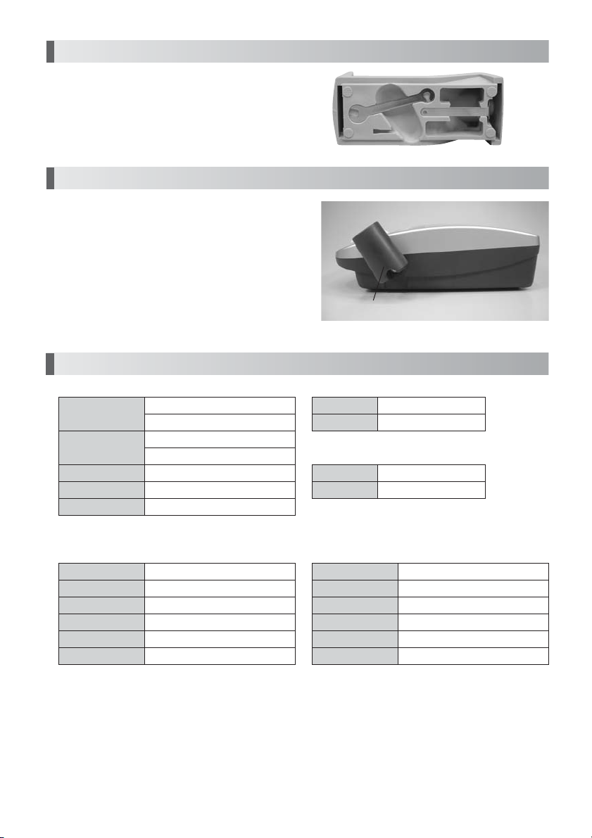
12. Handpiece Stand
At the bottom of the handpiece stand, tools
necessary for handpiece maintenance and a
spare chuck (optional) can be mounted.
(Fig. 14)
13. Handpiece Holder
The handpiece holder that can be mounted on
the right side of the control unit will widen a your
effective work area. Insert the holder into the slot
and fasten the screw. Adjust the holder angle to
your best position. (Fig. 15)
14. Specification
Control Unit
Model
Power supply
Rated Power
Weight
Dimensions
NE213-G (Gray)
NE213-W (White)
AC120V 50/60 Hz 46VA
AC230V 50/60 Hz 46VA
46VA
2.8kg
W167 x D247 x H77mm
Handpiece Holder
Food Pedal
Model
Weight
Handpiece
Model
Weight
Fig.14
Fig.15
FC-64
460g
Handpiece Stand
120g
Motor Handpiece
1 ) Torque Type
Model
Speed
Max. Torque
Weight
Dimensions
Cord Length
UMXL-T(P) / UMXL-T(P) 2M
1,000~50,000 min
8.7N · cm
215g ( exclude the cord)
L151 x ø 29mm
1.2m / 2.0m
-1
2 ) Compact Type
Model
Speed
Max. Torque
Weight
Dimensions
Cord Length
14
UMXL-C/ UMXL-C 2M
1,000~50,000 min
6 N · cm
181g ( exclude the cord)
L144 x ø 27mm
1.2m / 2.0m
-1
Page 17

15. Troubleshooting
Please check the following points before sending back instruments for repair.
<Unit / Motor>
Trouble Cause / Check Remedy
The power plug is disconnected.
Pilot Lamp does not
light
Control Unit display
“—“and “Setting
Rotation Speed”
alternately.
Foot Pedal
dose not work.
Error code E0
appears.
Error code E1
appears.
The motor and handpiece do not run, or Reset Lamp lights.
Error code E2
appears.
The fuse is blown.
Power Switch is faulty.
Power on the Control Unit
within pressing the Foot Pedal.
The connection of the Foot Pedal
cord plug is loose.
Hand/Foot Selector Switch is set
by HAND.
Maintenance mode (4) “Pd”:
Check to see if the Foot Pedal
operates normally.
Turn on the power again.
Turn on the power again.
If you have two or more units,
replace the motor and the motor
cord and check the operation.
The motor cord is disconnected.
If you have two or more units,
replace the motor and the motor
cord and check the operation.
Insert the power plug correctly.
Replace it with a specified fuse. If the
reason the fuse has blown is unknown,
ask for an inspection.
Ask for repair.
Power on the Control Unit without
pressing the Foot Pedal. When it does
not work definitely, take off the Foot
Pedal cord plug from the Control Unit
and Power it on. If it does not operate
correctly, ask for your dealer.
Even after you tried above and the
Control Unit could not operate
normally, contact your dealer for repair.
Connect the Foot Pedal cord plug
correctly.
Set Hand/Foot Selector Switch to
FOOT.
If the Foot Pedal dose not operates
normally, ask for repair of the Foot
Pedal or replace it with a new one.
If the same error code appears, ask for
repair of the Control Unit.
If it operates normally, the error display
is temporarily due to overload, which is
not a problem.
If it operates normally after replacing
the motor and the motor cord, the
motor and/or the motor cord may be
shorted. Ask for repair of the motor
and/or the motor cord. If the same
error code still appears after replacing,
ask for repair of the Control Unit.
Connect the motor cord correctly.
If it operates normally after replacing
the motor and the motor cord, the
motor and/or the motor cord may be
severed. Ask for repair of the motor
and/or the motor cord. If the same
error code still appears after replacing,
ask for repair of the Control Unit.
English
15
Page 18

Trouble Cause / Check Remedy
The motor cord is disconnected.
Maintenance mode (3) “HL”:
Confirm whether you work by a
motor signal check normally.
Error code E3
appears.
Error code E4
appears.
Error code E5
appears.
Error code E6
The motor and handpiece do not run, or Reset Lamp lights.
appears.
Error code E8
appears.
The chuck is open.
Check turning a bur with a finger
lightly and turning around it
lightly.
Vacuum-coupled Mode is on,
while the dust collector is not
used.
After stopping to cool it down
place for about 10 minutes,
check the operation again.
Turn on the power again, and
repeat starting and stopping
several times.
The chuck is open.
Maintenance mode (3) “HL”:
Confirm whether you work by a
motor signal check normally.
Check turning a bur with a finger
lightly and turning around it
lightly.
Turn on the power again.
If you have two or more units,
replace the motor cord and
check the operation.
Connect the motor cord correctly.
If any problem is found during a check,
the motor cord may be severed or the
sensor in the motor may be faulty. Ask
for repair.
Lock the chuck. If any problem is
found during a check, the motor cord
may be severed or the sensor in the
motor may be faulty. Ask for repair.
If the rotation is abnormal, ask for
repair of the motor and handpiece.
Make the Vacuum-coupled Mode to
be off. See Vacuum-coupled Mode
section in the manual. (See *
Vacuum-coupled Mode)
If it operates normally, there is no
problem. Check the operating
environment, storage location, etc., for
high temperature. If the same error
code appears frequently, ask for repair
of the Control Unit.
If it operates normally, there is no
problem. If the same error code appears,
ask for repair of the Control Unit.
Lock the chuck. If any problem is
found during a check, the motor cord
may be severed or the sensor in the
motor may be faulty. Ask for repair.
If any problem is found during a check,
the motor cord may be severed or the
sensor in the motor may be faulty. Ask
for repair.
If the rotation is abnormal, ask for
repair of the motor and handpiece.
Error indication is a temporary thing by
the overload if it work normally. There
is not it abnormally.
If it operates normally after replacing
the motor cord, the motor and/or the
motor cord may be shorted. Ask for
repair of the motor and/or the motor
cord. If the same error code still
appears after replacing the motor
cord, ask for repair of the Control Unit.
16
Page 19

Trouble Cause / Check Remedy
Error code E9
appears.
Error code EF
appears.
The motor and handpiece do not run, or Reset Lamp lights.
The rotation speed
does not rise.
If you have two or more units,
replace the motor cord and
check the operation.
Maintenance Mode (4) “Pd”:
Check whether Foot Pedal
operates normally by Foot Pedal
Chuck.
The maximum rotation speed for
operation by foot pedal should be
set with the Speed Control Knob.
If it operates normally after replacing
the motor cord, the motor and/or the
motor cord may be shorted. Ask for
repair of the motor and/or the motor
cord. If the same error code still
appears after replacing the motor
cord, ask for repair of the Control Unit.
If it does not operate normally, change
the Foot Pedal for new or ask for
repair.
Set the maximum rotation speed with
the Speed Control Knob.
<Handpiece>
Trouble Cause / Check Remedy
The handpiece does
not run with the
chuck tightened.
Heat is generated
during rotation.
Vibration or noise
occurs during rotation.
Run out of the bur
is heavy.
The bur comes out
Entry of foreign matter in the ball
bearings or seizure.
Entry of foreign matter in the ball
bearings, causing wear of the bearings.
Same as the above.
A bent bur is used.
Dust may be stuck in the chuck or
spindle.
The chuck is worn.
The ball bearings are worn.
The chuck is loose.
Send it to your dealer. Ask for
repair.
Same as the above.
Same as the above.
Replace the bur
Clean the inside of the chuck and
spindle.
Replace the chuck.
Send it to your dealer.
Tighten the chuck securely. (See
*Handling of Motor and
Handpiece.)
English
16. Disposing Product
Please consult with dealer from whom you purchased it about waste disposal.
17
Page 20

BEDIENUNGSANLEITUNG
Deutsch
Labor-Mikromotor
Page 21

Vielen Dank, dass Sie sich fur den Kauf des ULTIMATE XL entschieden haben. Bitte lesen Sie
die Anweisungen zur Bedienung, Pflege und Wartung in diesem Handbuch vor der
Inbetriebnahme sorgfaltig durch. Bewahren Sie dieses Bedienungshandbuch fur spatere
Verwendung auf.
Inhalt
Deutsch
WICHTIGE ANWEISUNGEN UND WARNUNG
1. Namen der Komponenten
2. Einrichten der Kontrolleinheit
3. Betriebsverfahren
4. Geschwindigkeitsbegrenzung
5. Schutzschalter für Motor
6. Memory-Funktion
7. Fehlercode
8. Auswechseln der Sicherung
9. Wartungsmodus
10. Kupplung an Absaugung
11. Handhabung von Motor und Handstück
12. Handstückablage
13. Handstückhalter
14. Technische Daten
15. Fehlerbehebung
16. Entsorgung des Produktes
····························································································
····························································································
······································································································
······························································································
····························································································
·····························································································
····························································································
······························································································
···············································································
···········································································
··········································································
·················································································
············································································
················································································
·············································································
·············································
·························································
21
25
26
27
28
28
28
29
30
30
31
32
34
34
35
35
38
WICHTIGE ANWEISUNGEN UND WARNUNG -Elektronische Geräte
WARNUNG!
Bei der Verwendung elektrischer Geräte sollten stets einige grundsätzliche
Vorsichtsmaßnahmen befolgt werden, um die Gefahr von Feuer, Stromschlag und eigenen
Verletzungen zu reduzieren. Dazu gehören die nachfolgenden Maßnahmen. Lesen Sie alle
diese Anweisungen vor dem Betrieb dieses Produkts durch und bewahren Sie sie auf.
21
Page 22
A. ERDUNGSANWEISUNGEN
1. Im Falle einer Fehlfunktion oder eines Ausfalls bietet die Erdung einen Weg des
geringsten Widerstands für den elektrischen Strom, um die Gefahr eines Stromschlags
zu reduzieren. Dieses Gerät ist mit einem Stromkabel ausgestattet, das einen
Erdungsleiter und einen geerdeten Stecker besitzt. Der Stecker muss in eine passende
Steckdose gesteckt werden, die korrekt installiert und entsprechend aller geltenden
Vorschriften geerdet ist.
2. Den mitgelieferten Stecker nicht verändern – wenn er nicht in die Steckdose passt,
lassen Sie die richtige Steckdose von einem qualifizierten Elektriker installieren.
3. Unsachgemäßer Anschluss des Erdungsleiters kann zur Gefahr eines Stromschlags
führen. Der Leiter mit einer grünen oder grün-gelb gestreiften Isolierung ist der
Erdungsleiter. Wenn eine Reparatur oder ein Austausch von Stromkabel oder Stecker
erforderlich ist, den Erdungsleiter nicht an einen stromführenden Pol anschließen.
4. Überprüfen Sie die korrekte Erdung des Geräts zusammen mit einem qualifizierten
Techniker oder Kundendienstmonteur, wenn Sie die Erdungsanweisungen nicht
vollständig verstanden haben oder im Zweifel darüber sind.
5. Nur dreiadrige Verlängerungskabel verwenden, die dreizinkige Erdungsstecker und die
richtigen Buchsen für den Stecker des Geräts haben.
6. Dieses Gerät ist zur Verwendung an einem Stromkreis vorgesehen, der eine Steckdose
wie in Zeichnung A (unten) besitzt (120 V). Das Gerät besitzt einen Stecker wie in
Zeichnung A (unten). Ein provisorischer Adapter, wie unten in den Zeichnungen B und C
dargestellt, kann verwendet werden, um diesen Stecker mit einer zweipoligen Dose zu
verbinden, wie in Zeichnung B zu sehen, wenn keine korrekt geerdete Steckdose zur
Verfügung steht. Der provisorische Adapter sollte nur so lange verwendet werden, bis
eine korrekt geerdete Steckdose von einem qualifizierten Elektriker installiert werden
kann. Das grüne, starre Öhr, der Zapfen und andere Vorsprünge des Adapters müssen
an eine permanente Erdung wie beispielsweise eine korrekt geerdete Steckdose
angeschlossen werden.
ERDUNGSPIN
Erdungsmethode
METALL-
SCHRAUBE
ABDECKUNG DER
GEERDETEN
STECKDOSE
22
ADAPTER
ERDUNGSMITTEL
ERDUNGSPIN
Page 23

7. Platzieren Sie die Anlage so, das im Storfall, die Stromversorgung einfach zu Unterbrechen
ist. Mindenstens 10cm Platz um das Gerät herum frei lassen.
Mindeststärke für Kabel
Mehr als
0
6
10
12
Nicht mehr als
6
10
12
16
Volts
120V
7,5m (25ft.) 15m (50ft.) 30m (100ft.) 45m (150ft.)
240V
15m (50ft.) 30m (100ft.) 60m (200ft.) 90m (300ft.)Ampere-Einstufung
Kabels Zahl
#18
#18
#16
#14
Gesamtlänge des Kabels
#16
#16
#16
#12
#16
#14
#14
Nicht empfohlen
#14
#12
#12
B. WEITERE WARNHINWEISE
1. Lesen Sie zu Ihrer eigenen Sicherheit vor der Verwendung des Geräts die
Bedienungsanleitung durch.
2. Augenschutz tragen.
3. Gebrochenen Schleifkörper sofort ersetzen.
4. Immer Schutzvorrichtung und Augenschutz verwenden.
5. Schleifscheiben nicht zu stark anziehen.
6. Nur mit dem Schleifer mitgelieferte Scheiben verwenden.
7. SCHRAUBENSCHLÜSSEL UND EINSTELLWERKZEUGE ENTFERNEN. Überprüfen Sie
grundsätzlich immer, ob alle Einstellwerkzeuge und Schraubenschlüssel entfernt sind,
bevor Sie das Gerät einschalten.
8. ARBEITSBEREICH SAUBER HALTEN. Unaufgeräumte Arbeitsbereiche und Werkbänke
provozieren Unfälle.
9. NICHT IN GEFÄHRLICHER UMGEBUNG VERWENDEN. Elektrische Geräte nicht an
feuchten oder nassen Orten verwenden oder sie dem Regen aussetzen. Für eine gute
Beleuchtung des Arbeitsfeldes sorgen.
10. Verletzungsgefahr durch unbeabsichtigtes Starten. Nicht in Bereichen verwenden, in
denen sich Kinder aufhalten können.
11. GERÄT NICHT ÜBERBEANSPRUCHEN. Es macht seine Arbeit besser und sicherer bei
der Drehzahl, für die es entwickelt wurde.
12. RICHTIGES WERKZEUG VERWENDEN. Werkzeug oder Zubehörteil nicht zwingen,
etwas zu machen, wofür es nicht geeignet ist.
13. ZWECKMÄSSIGE KLEIDUNG TRAGEN. Keine losen Kleidungsstücke, Handschuhe,
Halstücher, Ringe, Armbänder oder anderen Schmuck tragen, der von beweglichen
Teilen erfasst werden könnte. Rutschfestes Schuhwerk wird empfohlen. Bei langen
Haaren schützende Abdeckung tragen.
14. IMMER SICHERHEITSBRILLEN VERWENDEN. Normale Brillen haben nur
schlagresistente Gläser und sind KEINE Sicherheitsbrillen. Auch Gesichts- oder
Staubmaske tragen, wenn das Schleifen mit Staubentwicklung verbunden ist.
Deutsch
23
Page 24

15. WERKSTÜCK SICHERN. Verwenden Sie Klemmen oder einen Schraubstock, um das
Werkstück zu halten, wann immer dies möglich ist. Das ist sicherer als Ihre Hand und
macht beide Hände frei für die Bedienung des Geräts.
16. WERKZEUGE SORGFÄLTIG PFLEGEN. Werkzeuge scharf und sauber halten, für
optimale Leistung und Verringerung des Verletzungsrisikos für Personen. Die
Anweisungen zum Schmieren und Auswechseln von Zubehörteilen befolgen.
17. WERKZEUGE vor Wartungsarbeiten und Austausch von Zubehörteilen
HERAUSNEHMEN, wie beispielsweise Klingen, Bohreinsätze, Schneider und ähnliches.
18. GEFAHR EINES UNBEABSICHTIGTEN STARTENS REDUZIEREN. Sicherstellen, dass
der Schalter aus ist, bevor Sie das Gerät einstecken.
19. EMPFOHLENE ZUBEHÖRTEILE VERWENDEN. Empfohlene Zubehörteile finden Sie im
Benutzerhandbuch. Die Verwendung ungeeigneter Zubehörteile kann ein
Verletzungsrisiko für Personen dastellen.
20. NIEMALS LAUFENDES GERÄT UNBEAUFSICHTIGT LASSEN. AUSSCHALTEN. Gerät
nicht verlassen, bevor es zu völligem Stillstand gekommen ist.
21. Hinsichtlich der empfohlenen Drehzahlen für verschiedene Anwendungen bitte die
Anweisungen des Bohrerherstellers befolgen.
22. Das System funktioniert normal bei Umgebungsbedingungen mit einer Temperatur von
10–40 °C (50–104 °F), einer Luftfeuchtigkeit von 10–85 % RH und ohne
Feuchtigkeitskondensation im Steuergerät. Eine Verwendung außerhalb dieser
Grenzwerte kann eine Fehlfunktion verursachen.
23. Die Aktivierung des Unterbrechers bedeutet, dass der Motor zu stark belastet wird, über
seine Kapazität hinaus.
24. Der Unterbrecher dient zum Schutz des Motors, doch sollte die Arbeit stets so
durchgeführt werden, dass der Unterbrecher nicht aktiviert wird.
25. Die Spannzangenverriegelung nicht drehen, während das Handstück sich dreht.
26. Den Motor nicht laufen lassen, wenn der Bohrerverschlussring in der Stellung OFFEN ist
oder wenn kein Bohrer in der Spannzange montiert ist. Dies könnte zum Lösen des
Handstücks vom Motor oder plötzlicher Hitzeentwicklung führen.
27. Darauf achten, das Mikro Motorhandstück nicht auf den Fußboden oder auf eine harte
Fläche fallen zu lassen, um eine Beschädigung durch den Aufprall zu vermeiden.
28. Versuchen Sie nicht, das Produkt auseinanderzubauen oder zu verändern.
29. Achten Sie darauf, sich nicht am Schleifer oder dem Bohrer zu verletzen.
30. Achten Sie auf das korrekte Modell und die korrekte Leistung, wenn Sie die Sicherung
ersetzen.
C. Wichtige Anweisungen und Warnhinweise für ULTIMATE XL.
1. Weder Motor noch Handstück erfordern eine Schmierung, da die Kugellager beider
Komponenten mit Schmierfett imprägniert sind.
2. Verwenden Sie ausschließlich das Original-Netzkabel. Falls dieses beschädigt ist,
nehmen Sie Kontakt auf mit dem NSK / Nakanishi Service Center.
3. Senden Sie das Gerät zur Wartung / Reparatur zurück zum Hersteller.
24
Page 25
1. Namen der Komponenten
1
3
2
Deutsch
4
5
8 9
7
11
14
10
16
15
12
13
1
Steuereinheit
2
Motorhandstück
3
Fußpedal (FC-40)
4
Netzschalter
5
Motoranschluss
6
Handstückablage
7
Wahlschalter Vorwärts/Rückwärts
8
Hand-/Fuß-Wahlschalter
9
Motorschalter
10
Netzlampe
11
Resetlampe
12
Motorschalter Drehzahlregler
13
Drehzahlgrenzen-Freigabeknopf
14
Fußpedal-Anschluss
15
Eingangsbox
16
Netzkabel
6
25
Page 26
2. Einrichten der Kontrolleinheit
1. Montage des Motorhandstücks
Stecken Sie das Motorkabel in den
5
Motoranschluss, wobei Sie es nach der Rille
des Steckers ausrichten, und fixieren Sie den
Stecker durch Anziehen der Überwurfmutter.
(Abb. 1)
2. Montage des Fußpedals
Stecken Sie das Fußpedalkabel in den
Fußpedal-Anschluss, wobei Sie es nach der
14
Rille des Steckers ausrichten. (Abb. 2)
* Der Anschluss des Fußpedals ist nicht
erforderlich, wenn die Einheit nur von Hand
betrieben wird.
3. Anschluss des Netzkabels
Stecken Sie das Eingangsbox richtig und
fest in die Netzkabel auf der Rückseite der
Einheit. (Abb. 3)
15
16
Abb.1
Abb.2
26
Abb.3
Page 27

3. Betriebsverfahren
1. Netzkabel in eine Steckdose einstecken.
16
2. Sicherstellen, dass der Drehzahlgrenzen-Freigabeknopf auf der niedrigsten Einstellung
steht.
3. Ich schalte Netzschalter an.Ich bestätige diese angeschaltete Netzlampe.
4. Wählen Sie die Drehrichtung mit dem Wahlschalter Vorwärts/Rückwärts. Bei jedem
Drücken dieses Schalters ändert sich die Drehrichtung zwischen RECHTSLAUF und
LINKSLAUF.
5. Wählen Sie die Art der Steuerung mit dem Hand-/Fuß-Wahlschalter. Bei jedem Drücken
dieses Schalters ändert sich die Steuerungsart zwischen HAND und FUSS.
Betrieb - 1
4
Manueller Betrieb
6. Wählen Sie HAND mit dem Hand-/Fuß-Wahlschalter.
7. Stellen Sie die Umdrehungsgeschwindigkeit mit dem Motorschalter Drehzahlregler ein
und üperprüfen Sie diese auf der Resetlampe.
8. Drücken Sie auf den Motorschalter, dann beginnt der Motor zu laufen.
9. Um den Motor zu stoppen, den Motorschalter nochmals drücken.
Betrieb - 2
Betrieb mit Fußpedal
6. Wählen Sie FUSS mit dem Hand-/Fuß-Wahlschalter.
7. Stellen Sie die maximale Umdrehungsgeschwindigkeit mit dem Motorschalter
Drehzahlregler ein und überprüfen Sie diese auf der Resetlampe.
8. Drücken Sie das Fußpedal, dann beginnt der Motor zu laufen. Die
Umdrehungsgeschwindigkeit kann variabel bis zur Maximaldrehzahl gesteuert werden, je
nachdem, wie stark Sie das Fußpedal drücken.
Drehzahlautomatik
Um die Drehzahl innerhalb des eingestellten Bereichs zu fixieren, drücken Sie den
5
Motorschalter, während der Motor mit der gewünschten Geschwindigkeit läuft.
11
Resetlampe blinkt, und die Drehzahl kann beibehalten werden, auch wenn das
3
Fußpedal losgelassen wird. Um die Automatik abzuschalten, den Motorschalter
nochmals drücken oder das Fußpedal erneut drücken.
13
10
7
8
8
12
9
9
8
12
3
3
9
3
Deutsch
27
Page 28
Drehzahlbegrenzungs -Freigabetaste
Resetlampe
4. Geschwindigkeitsbegrenzung
Zur Verwendung eines Rosenbohrers mit
kleinem Durchmesser oder eines Finierers bei
-1
40.000 Min.
Drücken des Drehzahlgrenzen-Freigabeknopf
(Upm) oder mehr erlaubt das
13
und Drehen des Drehzahlreglers eine Einstellung
-1
von bis zu 50.000 Min.
(Upm).(Abb. 4)
Drehzahlbegrenzungs -Freigabetaste
Drehzahlbegrenzungs -Freigabetaste
Abb.4
VORSICHT
Eine Drehzahl von 40.000 Min.-1 (Upm) oder mehr ist nur erlaubt, wenn der
Bohrerhersteller die zulässige Drehzahl für einen bestimmten Bohrer entsprechend
angibt.
5. Schutzschalter für Motor
Wenn der Motor mit einer zu hohen Belastung
betrieben wird oder das Handstück nicht mehr
rund läuft, stoppt der Schaltkreis zum Schutz
des Motors und der Einheit die Stromversorgung
des Motors, Resetlampe leuchtet und eine
Fehlermeldung auf der Resetlampe erscheint.
(Abb.5)
Schutzschalter zurücksetzen
Bei manuellem Betrieb kann er durch erneutes Drücken des Motorschalters zurückgesetzt
werden. Beim Betrieb mit Fußpedal das Fußpedal zurücknehmen, um zu stoppen; dann
wird der Schutzschalter zurückgesetzt.
11
Resetlampe
Resetlampe
Abb.5
5
3
6. Memory-Funktion
Wenn der Netzschalter eingeschaltet wird, werden die zuletzt verwendeten Einstellungen
von Laufrichtung und HAND-/FUSS-Auswahl wiederhergestellt. Sie sollten besonders auf die
richtige Laufrichtung achten.
4
28
Page 29

8. Auswechseln der Sicherung
Die Sicherung befindet sich in der Eingangsbox
Verriegelungsklemmen Verriegelungsklemmen
oben und unten an der Eingangsbox lösen und
herausziehen, um die Sicherung auszuwechseln
(Abb.6)
Wenn die Sicherung durchgebrannt ist,
wechseln Sie bitte die Sicherung aus und
drücken Sie den Sicherungshalter in die
ursprüngliche Position.
- Sicherung: Bestellnummer (120V): 1202225010 (T2,5AH 250V)
- Sicherung: Bestellnummer (230V): 1202216010 (T1,6AH 250V)
15
Abb.6
VORSICHT
Die Sicherung brennt durch, wenn ein Kurzschluss auftritt oder wenn eine
Überspannung in die primäre Stromversorgung fließt. Wenn die Ursache unklar ist, das
Produkt zur Inspektion an einen autorisierten NSK Kundendienst schicken.
9. Wartungsmodus
Die Einheit ist mit einem Wartungsmodus zur Funktionsprüfung von Schaltern, Anzeige,
Fußpedal, Motor usw. ausgestattet. Gleichzeitig Hand-/Fuß-Wahlschalter und
5
Motorschalter drücken, Netzschalter einschalten und gedrückt halten, bis ein Piepsignal
ertönt (etwa 2 Sekunden). Jetzt den Drehzahlregler von der Minimalstellung aus drehen, damit
im Display „oP“, „dP“, „HL“, „Pd“ und „in“ für die nachfolgenden Überprüfungen angezeigt wird.
Zum Verlassen des Wartungsmodus Netzschalter aus- und erneut einschalten.
8
(1) "oP": Schalterprüfung (Überprüfung Betrieb)
Die Schalter auf dem Bedienfeld drücken, damit die rechten und/oder linken Lampen
leuchten und überprüft werden kann, ob die Schalter normal funktionieren.
(2) "dP": Displayprüfung
7
Wahlschalter Vorwärts/Rückwärts drücken, und die Lampen leuchten nacheinander, damit
überprüft werden kann, ob sie normal funktionieren. Um diese Prüfung abzubrechen, den
7
Wahlschalter Vorwärts/Rückwärts erneut drücken.
30
Page 30

(3)
"HL": Motorsignal-Prüfung (Hall IC Prüfung)
7
Wahlschalter Vorwärts/Rückwärts drücken, und die Resetlampe zeigt eine oder zwei
horizontale Linien an. Den Motor langsam von Hand drehen, dann ändert sich diese Anzeige
abwechselnd zu einer Linie, zwei Linien, einer Linie, zwei Linien ... von oben nach unten und
von unten nach oben. Wenn eine der drei Linien nicht leuchtet, ist der Sensor (Hall IC) im
Motor defekt oder das Kabel überlastet und deshalb eine Reparatur erforderlich. Um diese
Prüfung abzubrechen, den Wahlschalter Vorwärts/Rückwärts erneut drücken.
Eg.
2 3 4 A b C d C b A 4 3 2
7
11
(4) "Pd": Fußpedalprüfung
7
Wahlschalter Vorwärts/Rückwärts erneut drücken, und die Resetlampe ändert sich. In
normaler Zeit ändert sich die Resetlampe zu Hexadezimalangaben (0~9, A~F), je
nachdem, wie weit das Fußpedal gedrückt wird. Beim Drücken des Pedals leuchtet auch die
10
Netzlampe leicht auf, und ein vollständiges Herunter-drücken des Pedals löscht die
Lampe. Wenn sich die Resetlampe nicht ändert oder die Resetlampe nicht korrekt
leuchtet, kann das Fußpedal defekt sein. Um diese Prüfung abzubrechen, den
7
Wahlschalter Vorwärts/Rückwärt erneut drücken.
3
11
11
11
(5) "in": Initialisierungsfunktion
7
Wahlschalter Vorwärts/Rückwärt drücken, dann ertönt ein Piepsignal und Laufrichtung,
HAND/FUSS und andere Einstellungen kehren zu den werkseitigen Voreinstellungen zurück.
Laufrichtung : FWD (Vorwärts; Rechtslauf)
HAND/FUSS : HAND
Kupplung an Absaugung : AUS
Deutsch
10. Kupplung an Absaugung
An einigen Zahntechnik-Arbeitstischen mit Absauganlage kann der Motor gekoppelt an die
Absaugung verwendet werden. Wenn eine solche Absauganlage* verwendet wird, kann der
Stromverbrauch des ULTIMATE XL reguliert werden, damit die Kopplung an die Absaugung
funktioniert. Wenn Sie eine Kopplung an die Absaugung verwenden möchten, wählen Sie den
Modus wie folgt:
Modus wählen
Bei gedrücktem Wahlschalter Vorwärts/Rückwärt den Netzkabel einschalten, dann kann
der Modus gewählt werden. Ein langer Piepton zeigt den Absaug-Modus an und zwei kurze
Pieptöne den nicht gekoppelten (energiesparenden) Modus an. Bei jeder Wahl mit dem
Schalter ändert sich der Modus von gekoppelt zu nicht gekoppelt.
* Eine derzeit bekannte Absauganlage ist KAVO EWL-560.
7
31
16
Page 31

11. Handhabung von Motor und Handstück
Lösen
Loosen
(1) Bohrer einsetzen oder herausnehmen
Das Spannfutter wird durch Drehen des
Verriegelungsrings in die Stellung OFFEN geöffnet.
Die Spannzange wird gelöst und der Bohrer kann
herausgenommen werden. Durch Drehen des
Rings in Richtung SCHLIESSEN wird das
Spannfutter geschlossen, und der Bohrer kann
montiert werden. Dann den Ring drehen, bis es
klickt. (Abb.7)
SCHLIESSEN
Öffnen
VORSICHT
• Die Spannzangenverriegelung nicht drehen, während das Motor sich dreht.
• Den Motor nicht laufen lassen, wenn der Bohrerverschlussring in der Stellung OFFEN
ist oder wenn kein Bohrer in der Spannzange montiert ist. Dies könnte zum Lösen des
Handstücks vom Motor oder plötzlicher Hitzeentwicklung führen.
(2) Reinigung und Austausch des
Spannfutters
(1) Spannfutter herausnehmen
Zum Herausnehmen des Spannfutters den
Ring öffnen und das Spannfutter mit dem
mitgelieferten Schraubenschlüssel gegen den
Uhrzeigersinn drehen. (Abb. 8)
* Wenn ein Bohrer mit großem Durchmesser
schneidender Teile bei hohem Drehmoment
verwendet wird, kann sich das Spannfutter in
Richtung Schließen drehen, sodass der
Bohrer festsitzt und sich nicht
herausnehmen lässt. In diesem Fall den
Schlitz der Nase entsprechend der
Schraubenschlüsselposition der Welle
ausrichten (flacher Teil) und die Welle mit
einem L-Schlüssel festhalten. Den Ring
öffnen und das Spannfutter mit dem
mitgelieferten Schraubenschlüssel gegen
den Uhrzeigersinn drehen, um es
herauszunehmen. (Abb. 9)
Lösen
Lösen
Loosen
Loosen
Abb.7
Abb.8
Abb.9
32
Page 32

(2) Spannfutter reinigen
Drehen Sie handfest an.
Spannfutter so oft wie möglich herausnehmen und im Ultraschallreiniger reinigen.
Mindestens ein Mal pro Woche reinigen.
VORSICHT
Eine Vernachlässigung der Reinigung über einen längeren Zeitraum ist sehr gefährlich,
da sich Wachs, Gips usw. Im Spannfutter ansammeln und der Bohrer nicht sicher
gehalten wird oder gar herausfällt.
(3) Spannfutter einsetzen und einstellen
Vor dem Einsetzen dünn Öl auftragen.
Den Ring öffenen, Testbohrer oder gerade
verwendeten Bohrer in das Spannfutter
setzen und dann das Spannfutter von Hand
im Uhrzeigersinn drehen, bis es stoppt. Dann
den Ring verriegeln; das Spannfutter kann
den Bohrer sicher festhalten. (Abb. 10)
Drehen Sie handfest an.
Drehen Sie handfest an.
VORSICHT
Bevor Sie das Handstück benützen, prüfen Sie bitte auf jeden Fall, daß das rotierende
Teil (Schleifkörper etc.) sicher montiert ist und sich nicht herausziehen lässt.
3. Motorkabel und Motor verbinden und trennen
Kabel-Überwurfmutter am hinteren Ende des Motors abnehmen, dann kann der
Motorkabelstecker herausgezogen werden. Zum Anschließen Steckerstift und Loch im
Motorkabel-Stecker ausrichten und den Stecker gerade bis zum Anschlag einstecken. Dann
die Überwurfmutter anziehen.
* Stecker beim Einsetzen nicht drehen oder verkanten.
Deutsch
Abb.10
4.
Handstück vom Motor abnehmen
Handstück und Motor sind in der Mitte
verschraubt. Jeweils Außengehäuse von
Handstück und Motor festhalten und gegen
den Uhrzeigersinn drehen, um beide zu trennen.
(Abb. 12) Beim Verbinden von Motor und
Handstück folgende VORSICHTSMASSNAHME
beachten.
Abb.11
Abb.12
33
Page 33

VORSICHT
Beim Verbinden von Handstück und Motor das
Handstück im Uhrzeigersinn drehen und fest
anziehen. Wenn der Mitnehmer nicht korrekt
einrastet, kann das Handstück nicht ganz angezogen
werden. In diesem Fall keine Gewalt anwenden.
Handstück lösen und den Bohrer kurz drehen, um die Antriebsklaue neu auszurichten.
Handstück wieder verbinden und fest anziehen. (Abb. 13)
Typ Torque / Typ Kompakt
12. Handstückablage
Im Boden der Handstückablage können für die
Wartung benötigte Werkzeuge und ein
Ersatz-Spannfutter (optional) aufbewahrt
werden. (Abb. 14)
13. Handstückhalter
Der Handstückhalter kann an der rechten Seite
der Einheit montiert werden und vergrößert so
Ihren effektiven Arbeitsbereich. Halter in den
Schlitz einsetzen und Schraube anziehen. Winkel
des Halters in der für Sie optimalen Position
einstellen. (Abb. 15)
Handstückhalter
Abb.13
Abb.14
Abb.15
34
Page 34

14. Technische Daten
Kontrolleinheit
Modell
Stromversorgung
Nennleistung
Gewicht
Abmessungen
NE213-G (Grau)
NE213-W (Weiß)
AC120V 50-60 Hz
AC230V 50-60 Hz
46VA
2,8kg
W167 x D247 x H77mm
Motorhandstück
1 ) Typ Drehmoment (Torque)
Modell
Drehzahl
Drehmoment
Gewicht
Abmessungen
Kabellänge
UMXL-T(P) / UMXL-T(P) 2M
1.000~50.000 min
8·7N · cm
215g (ohne Motorkabel)
L151 x ø 29mm
2,0m
-1
Fußpedal
Modell
Gewicht
FC-64
460g
Handstückablage
Modell
Gewicht
Handstückablage
120g
2 ) Typ Kompakt
Modell
Drehzahl
Max. Drehmoment
Gewicht
Abmessungen
Kabellänge
UMXL-C 2M
1.000~50.000 min
6 N · cm
181g (ohne Motorkabel)
L144 x ø 27mm
2,0m
15. Fehlerbehebung
Bitte folgende Punkte überprüfen, bevor Sie das Instrument zur Reparatur einschicken.
<Kontrolleinheit und Motor>
Problem Ursache / Überprüfen Abhilfe
Netzstecker richtig einstecken.
Durch angegebene Sicherung ersetzen.
Wenn die Ursache für das Durchbrennen
unbekannt ist, um Inspektion bitten.
Reparieren lassen.
Schalten Sie die Steuereinheit ohne
Drücken des Fußpedals ein. Wenn es
definitiv nicht funktioniert, ziehen Sie den
Fußpedalkabelstecker von der
Steuereinheit ab und schalten Sie diese
ein. Bei Fehlfunktion wenden Sie sich an
Ihren Händler.
Wenn die Steuereinheit auch nach
Ausführen der obigen Maßnahmen nicht
richtig arbeitet, wenden Sie sich an Ihren
Händler zur Reparatur.
Pilotlampe leuchtet
nicht.
Die Steuereinheit
zeigt abwechselnd
“—“ und “Setting
Rotation Speed” an.
Der Netzstecker ist ausgesteckt.
Die Sicherung ist durchgebrannt.
Netzschalter ist defekt.
Schalten Sie die Steuereinheit durch
Drücken des Fußpedals ein.
Deutsch
-1
35
Page 35

Problem Ursache / Überprüfen Abhilfe
Der Stecker desFußpedals ist
locker.
Hand-/Fuß-Wahlschalter ist auf
Fußpedal geht
nicht.
Fehlercode E0
erscheint.
Fehlercode E1
erscheint.
Fehlercode E2
erscheint.
Motor und Handstück laufen nicht oder Resetlampe leuchtet delete.
Fehlercode E3
erscheint.
HAND gestellt.
Im Wartungsmodus (4) “Pd”:
Fußpedal-Prüfung überprüfen, ob
das Fußpedal normal funktioniert.
Gerät nochmals einschalten.
Gerät nochmals einschalten.
Wenn Sie zwei oder mehrere
Einheiten haben, Motor und
Motorkabel austauschen und
Funktion prüfen.
Das Motorkabel ist nicht
angeschlossen.
Wenn Sie zwei oder mehrere
Einheiten haben, Motor und
Motorkabel austauschen und
Funktion prüfen.
Das Motorkabel ist nicht
angeschlossen.
Im Wartungsmodus (3) “HL”:
Motorsignal-Prüfung überprüfen, ob
das Gerät normal funktioniert.
Das Spannfutter ist offen.
Überprüfen, ob die Spitze leicht mit
der Hand gedreht werden kann.
Fußpedalstecker korrekt einstecken.
Hand-/Fuß-Wahlschalter auf FUSS
stellen.
Wenn das Fußpedal nicht normal
funktioniert, reparieren lassen oder durch
neues Pedal ersetzen.
Wenn der gleiche Fehlercode erneut
erscheint, die Einheit reparieren lassen.
Wenn es normal funktioniert, ist die
Fehleranzeige nur vorübergehend und
beruht auf einer Überlastung, was jedoch
kein echter Fehler ist.
Wenn das Gerät nach Austausch von
Motor und Kabel normal funktioniert,
können Motor und/oder Motorkabel
kurzgeschlossen sein. Motor und/oder
Kabel reparieren lassen. Wenn der
gleiche Fehlercode nach dem Austausch
erneut erscheint, die Einheit reparieren
lassen.
Schließen Sie das Motorkabel richtig an.
Wenn das Gerät nach Austausch von
Motor und Kabel normal funktioniert,
können Motor und/oder Motorkabel
kurzgeschlossen sein. Motor und/oder
Kabel reparieren lassen. Wenn der
gleiche Fehlercode nach dem Austausch
erneut erscheint, die Einheit reparieren
lassen.
Um die Genauigkeit der Spannzange zu
erhalten.
Wenn sich bei der Überprüfung irgendein
Problem ergibt, kann das Motorkabel
überlastet oder der Sensor im Motor
defekt sein. Reparieren lassen.
Spannfutter verriegeln.
Wenn die Drehung abnormal ist, Motor
und Handstück reparieren lassen.
36
Page 36

Problem Ursache / Überprüfen Abhilfe
Absaug-Modus ist an, während
Absaugung nicht verwendet wird.
Fehlercode E4
erscheint.
Fehlercode E5
erscheint.
Fehlercode E6
erscheint.
Fehlercode E8
erscheint.
Motor und Handstück laufen nicht oder Resetlampe leuchtet delete.
Fehlercode E9
erscheint.
Fehlercode EF
erscheint.
Nach Anhalten und 10 Minuten
Abkühlung Funktion nochmals
überprüfen.
Gerät nochmals einschalten und
mehrere Male starten/stoppen.
Das Spannfutter ist offen.
Im Wartungsmodus (3) „HL“:
Motorsignal-Prüfung überprüfen, ob
das Gerät normal funktioniert.
Überprüfen, ob die Spitze leicht mit
der Hand gedreht werden kann.
Gerät nochmals einschalten.
Wenn zwei oder mehrere Einheiten
zur Verfügung stehen, Motor und
Motorkabel austauschen und
Funktion prüfen.
Wenn zwei oder mehrere Einheiten
zur Verfügung stehen, Motor und
Motorkabel austauschen und
Funktion prüfen.
Wartungsmodus (4) “Pd” : Das
Fußpedal überprüfen, ob das
Fußpedal normal funktioniert.
Absaug-Modus ausschalten. Siehe
Abschnitt Absaug- Modus in dieser
Gebrauchsanleitung.
Wenn das Gerät normal funktioniert, liegt
kein Fehler vor. Betriebsumgebung,
Aufbewahrungsort usw. Auf hohe
Temperatur überprüfen. Wenn der gleiche
Fehlercode häufig erscheint, Einheit
reparieren lassen.
Wenn das Gerät normal funktioniert, liegt
kein Fehler vor. Wenn der gleiche
Fehlercode wieder erscheint, Einheit
reparieren lassen.
Spannfutter verriegeln.
Wenn sich bei der Überprüfung irgendein
Problem ergibt, kann das Motorkabel
überlastet oder der Sensor im Motor
defekt sein. Reparieren
lassen.
Wenn die Drehung abnormal ist, Motor
und Handstück reparieren lassen.
Bei normalem Betrieb, ist die
Fehleranzeige nur vorübergehend und
beruht auf einer Überlastung. Dies ist
jedoch kein echter Fehler.
Wenn bei der Überprüfung
Unregelmäßigkeiten entdeckt werden,
dann kann es möglich sein, dass das
Motorkabel unterbrochen oder der
Sensor im Motor defekt ist. Reparieren
lassen. Falls ein Turbinenadapter
verwendet wird, dann ist möglicherweise
das Turbinenadapterkabel unterbrochen
oder der Turbinenadapter defekt.
Reparieren lassen.
Wenn das Fußpedal nicht normal
funktioniert, reparieren lassen oder durch
neues Pedal ersetzen.
37
Deutsch
Page 37

Problem Ursache / Überprüfen Abhilfe
Die Drehzahl steigt
nicht.
Die maximale Drehzahl für den
Betrieb mit Fußpedal muss mit dem
Drehzahlregler eingestellt werden.
Maximale Drehzahl mit dem
Drehzahlregler einstellen.
<Handstück>
Problem Ursache Abhilfe
Das Handstück läuft bei
angezogenem
Spannfutter nicht.
Während der Rotation
entsteht Hitze.
Vibration oder Geräusche
treten während der
Rotation auf.
Bohrer läuft sehr lange
nach.
Der Bohrer kommt
heraus.
Eindringen von Fremdmaterial in Kugellager
oder Blockieren.
Eindringen von Fremdmaterial in die
Kugellager verursacht Abnutzung der Lager.
Wie oben.
Es wird ein verbogener Bohrer verwendet.
Im Spannfutter oder in der Welle kann Staub
sitzen.
Das Spannfutter ist abgenutzt.
Die Kugellager sind abgenutzt.
Das Spannfutter ist lose.
An Ihren Händler schicken.
Reparieren lassen.
Wie oben.
Wie oben.
Bohrer ersetzen.
Spannfutter und Welle Innen
reinigen.
Spannfutter ersetzen.
An Ihren Händler schicken.
Spannfutter einstellen.
16. Entsorgung des Produktes
Bitte wenden Sie sich bezüglich Abfallentsorgung an den Händler, von dem Sie das Produkt
gekauft haben.
38
Page 38

Manuel Technique
Français
Moteur de laboratoire
Page 39

Nous vous remercions d’avoir acheté ULTIMATE XL.
Nous vous recommandons de lire attentivement ce manuel technique notamment les
instructions concernant l’utilisation, la méthode de manipulation, la maintenance ainsi que
l’inspection avant d’utiliser l’appareil et de ranger ce manuel dans un endroit où vous pourrez le
consulter à tout moment.
Table des matières
INSTRUCTIONS IMPORTANTES ET PRECAUTIONS POUR LES DISPOSITIFS
ELECTRIQUES
1. Désignation des éléments
2. Installation
3. Mise en route
4. Limiteur de Vitesse
5. Protection du circuit électronique
6. Mémoire
7. A propos du code d'erreur
8. Remplacement des fusibles
9. Mode de maintenance
10. Aspiration couplée à l’Ultimate XL
11. Manipulation du moteur et de la pièce à main
12. Support moteur
13. Support Pièce à main
14. Caractéristiques
15. Pannes et dispositions à prendre
16. Mis au rebut de l’instrument
······························································································
···············································································
·······································································································
··································································································
··························································································
····································································
·········································································································
··············································································
············································································
····················································································
··································································
·················································
······························································································
·····················································································
·····························································································
···································································
···········································································
41
45
46
47
48
48
48
49
50
50
52
52
55
55
55
56
58
Français
INSTRUCTIONS IMPORTANTES ET PRECAUTIONS POUR LES DISPOSITIFS ELECTRIQUES
PRECAUTIONS
Lors de l’utilisation d’appareils électriques, il faut toujours suivre les précautions de base de
sécurité afin de limiter les risques d’incendie, d’électrochoc et les blessures corporelles.
Lisez toutes ces instructions avant de faire fonctionner cet appareil et gardez-les près de
vous.
41
Page 40

A. INSTRUCTIONS POUR LA MISE A LA TERRE
1. En cas de mauvais fonctionnement ou de panne, la mise à la terre offre une voie de
résistance minime pour le courant électrique afin de réduire le risque d’électrochoc. Cet
appareil est fourni avec un cordon électrique équipé d’une prise de. Ce cordon électrique
doit être connecté à une prise adaptée qui sera correctement installée et mise à la terre
conformément à tous les codes et réglementations locales.
2. Ne modifiez pas la fiche fournie. Si elle ne convient pas à votre branchement, demandez à un
électricien qualifié d’installer une prise adéquate.
3. Une connexion incorrecte du conduteur de mise à la terre principale peut provoquer un
électrochoc. Le conducteur avec une isolation ayant une surface extérieure verte avec ou
sans raies jaunes est le conducteur de mise à la terre principale. S’il est nécessaire de
réparer ou de remplacer le cordon électrique ou la fiche, ne branchez pas le conducteur de
mise à la terre principale sur une phase ou un neutre.
4. Vérifiez avec un électricien qualifié ou une personne du service après-vente si les instructions
de la mise à la terre ne sont pas respectées, ou si un doute subsiste quant à la mise à la
terre correcte de cet appareil.
5. Utilisez uniquement des rallonges électriques avec des mises à la terre.
6. Cet outil a été conçu pour une utilisation sur un circuit qui ait une sortie comme celle indiquée
dans l’illustration A dans la figure (ci-dessous) (120V). Un adaptateur temporaire, semblable à
celui de l’illustration B et C, doit être utilisé pour brancher cette fiche à une prise femelle à 2
pôles comme indiqué dans l’illustration B si une sortie de mise à la terre correcte n’est pas
disponible. L’adaptateur temporaire ne doit être utilisé qu’en attendant qu’une sortie de mise
à la terre correcte puisse être installée par un électricien qualifié. L’oreille rigide verte, la cosse
pour câble ou autre pièce, allongeant l’adapteur doit être branchée à une mise à la terre
permanente notamment à une boîte de sortie de mise à la terre correcte.
GROUNDING
PIN
Méthode de mise à la terre
METAL SCREW
COVER IF GRIUNDING
OUTLET BOX
42
ADAPTER
GROUNDING MEANS
GROUNDING PIN
Page 41

7. UTILISEZ UNE RALLONGE CORRECTE. Assurez-vous du bon état de votre rallonge. Quand
vous l’utilisez, vérifiez bien qu’’elle est suffisamment puissante pour apporter le courant
nécessaire à votre appareil. Un cordon de dimension inférieure à la cote préconisée peut
provoquer une baisse dans la tension de ligne engendrant une perte de puissance et une
surchauffe. Le tableau (ci-dessous) indique la taille correcte à utiliser suivant la longueur du
cordon et la valeur nominale sur la plaque caractéristique. En cas de doute, utilisez la plus
haute cote suivante. Plus le numéro de cote est faible, plus le cordon est puissant.
8. Installez l’equipement de facon a pouvoir rapidement enlever la prise de courant en cas
d’urgence. Ne placez aucun objet dans un périmètre de 10 cm autour de l’unité.
Valeur minimale pour le cordon électrique
Longueur totale du cordon
#16
#16
#16
#12
#16
#14
#14
Non recommandée
#14
#12
#12
Supérieure à
0
6
10
12
Pas plus de
6
10
12
16
Volts
7,5m (25pieds) 15m (50pieds) 30m (100pieds) 45m (150pieds)
120V
15m (50pieds) 30m (100pieds) 60m (200pieds) 90m (300pieds)Valeur nominale
240V
Cordon Nombre
#18
#18
#16
#14
B. AUTRES INSTRUCTIONS DE PRECAUTIONS
1. Pour votre propre sécurité, lisez le manuel d’instructions avant de manipuler l’appareil.
2. Portez des lunettes de protection.
3. Remplacez immédiatement tout accessoire cassé.
4. Utilisez toujours des protections pour les yeux.
5. Ne serrez pas trop les écrous de fixation.
6. RETIREZ LES CLES ET LES BOULONS DE REGLAGE. Prenez l’habitude de vérifier que les
clés et les boulons de réglage sont retirés de l’outil avant de le mettre en marche.
7. GARDEZ TOUJOURS LE POSTE DE TRAVAIL PROPRE. Des postes de travail ou des bancs
encombrés peuvent provoquer des accidents.
8. N’UTILISEZ PAS CET APPAREIL DANS UN ENVIRONNEMENT DANGEUREUX. N’utililsez
pas d’outils électriques dans des lieux humides et mouillés. Gardez votre poste de travail
bien éclairé.
9. Risque de blessure en cas de démarrage accidentel. N’utilisez pas l’appareil dans un lieu où
il y a des enfants.
10. NE FORCEZ PAS L’APPAREIL. Il fera un meilleur travail s’il fonctionne à la vitesse pour
laquelle il a été conçu.
11. UTILISEZ LE BON OUTIL. Ne forcez pas l’outil ou sa fixation pour effectuer un travail pour
lequel l’appareil n’a pas été conçu.
12. PORTEZ UNE TENUE PROFESSIONNELLE ADAPTEE A VOTRE TRAVAIL. Ne portez pas de
vêtements amples, de gants, de cravate, de bagues, de bracelets ou autres bijoux qui
pourraient se coincer dans les pièces mobiles. Des chaussures non-glissantes sont
recommandées. Portez un bonnet de protection pour les cheveux longs.
Français
43
Page 42

13. UTILISEZ TOUJOURS DES LUNETTES DE PROTECTION. Les lunettes de vue ont des
verres résistants uniquement aux impacts, ce ne sont PAS des lunettes de protection. Utilisez
aussi un masque contre la poussière si nécessaire.
14. TRAVAILLEZ EN TOUTE SECURITE. Utilisez si nécessaire des crampons ou un étau pour
maintenir la pièce à usiner pendant le travail. Ceci est plus sûr que d’utiliser votre main et
ceci libère vos deux mains pour manipuler l’outil.
15. ENTRETENEZ L’APPAREIL AVEC SOIN. Gardez l’appareil propre pour une meilleure
performance et pour réduire les risques de blessure corporelle. Suivez les instructions
concernant la lubrification et le remplacement des accessoires.
16. DEBRANCHEZ LES OUTILS avant l’entretien : lors du remplacement des accessoires
notamment les lames, les mèches et les couteaux.
17. REDUISEZ LES RISQUES DE DEMARRAGE HASARDEUX. Assurez-vous que l’interrupteur
est sur la position OFF avant de brancher l’appareil.
18. UTILISEZ LES ACCESSOIRES RECOMMANDES. Consultez le manuel d’utilisation pour
connaître les accessoires recommandés. L’utilisation d’accessoires incorrects peut entraîner
accident et /ou blessures corporelles.
19. NE LAISSEZ JAMAIS L’APPAREIL EN MARCHE SANS SURVEILLANCE. TOUJOURS
L’ETEINDRE.
20. Pour la vitesse de marche recommandée pour diverses applications, veuillez suivre les
instructions des fabricants de fraises.
21. Le système fonctionne normalement dans un environnement où la température est de 0 à
40ºC, l’humidité est de 10 à 85%RH et où aucune condensation n’existe dans l’unité. Utiliser
l’appareil en dehors de ces limites peut entraîner un mauvais fonctionnement de celui-ci.
22. Rangez le système dans un lieu où la temperature est de -10 à 60ºC, l’humidité est de 10 à
85%RH, la pression atmosphérique de 500 à 1060hPa et où il n’y a ni poussière, ni soufre, ni
sel dans l’air.
23. Un choc important, par exemple : la chute du boîtier de contrôle ou du micromoteur, peut
provoquer des dégats.
24. Ne tournez pas la bague de verrouillage de la fraise tant que le moteur tourne.
25. Ne faites pas tourner le moteur lorsque la bague de verrouillage de la fraise est en position
OPEN (ouverte), ou qu’aucune fraise n’ait été installée dans le mandrin. Ceci pourrait
provoquer une déconnexion du moteur ou de la pièce à main ou générer une soudaine
surchauffe.
26. L’activation du coupe-circuit signifie qu’une pression excessive, supérieure à la capacité du
moteur, a été appliquée au moteur. Ce coupe-circuit a été conçu pour protéger le moteur
mais il est préférable d’effectuer le fraisage sans l’activer.
27. Il faut faire attention à ne pas faire tomber le micromoteur sur le sol ou sur une surface dure
afin d’éviter de l’endommager.
28. Ne démontez et n’altérez pas vous-même le produit.
29. Veillez à ne pas vous blesser avec la meule ou la fraise.
30. Lorsque vous remplacez le fusible, veillez à sélectionner le modèle et la puissance corrects.
44
Page 43

C. INSTRUCTIONS IMPORTANTES ET PRECAUTIONS SUR L’ULTIMATE XL
1. Le moteur et la pièce à main ne doivent pas être lubrifiés car les roulements à billes du
moteur ainsi que ceux de la pièce à main le sont déjà.
2. Utilisez exclusivement le cordon d’alimentation original. En cas de dommages, veuillez
contacter le service après-vente NSK/Nakanishi.
3. Equipement à renvoyer au fabricant pour service/réparation.
1. Désignation des éléments
1
3
2
Français
4
5
8 9
7
11
14
10
1
Boîter de contrôle
2
12
13
15
16
Moteur et Pièce à main
3
Pédale de commande (FC-64)
4
Interrupteur Marche/Arrêt
5
Prise moteur
6
Support moteur
7
Inversion du sens de rotation
8
Sélecteur Manuel/Pédale
9
Mise en marche du moteur
10
Témoin de fonctionnement du moteur
11
Affichage digital de la vitesse
12
Variateur de vitesse de rotation
13
Butée de limitation de vitesse de rotation
14
Prise de la Pédale
15
Boîtier fusible
16
Branchement secteur
6
45
Page 44

2. Installation
1. Branchement du moteur
Insérer la prise du cordon moteur dans la fiche
du boîtier, bien aligner les broches et visser
5
pour un bon maintien. (Fig. 1)
2. Branchement de la pédale
Insérer la prise de la pédale au niveau de la
fiche du boîtier situé sur la face arrière du
boîtier de contrôle en alignant les broches. Ne
pas forcer. (Fig. 2)
3. Branchement du cordon secteur
Insérer correctement la prise du Cordon
secteur dans la fiche du boîtier située sur la
face arrière du boîtier de contrôle. (Fig. 3)
14
16
15
Fig.1
Fig.2
46
Fig.3
Page 45

3. Mise en route
3
16
12
4
8
8
9
8
3
9
3
9
3
10
7
12
9
12
1. Brancher le Cordon d’alimentation à la prise secteur.
2. Assurez-vous que le Variateur de vitesse soit au minimum ( tourner le bouton vers la
gauche).
3. Mettre l’Interrupteur Marche/Arrêt sur ON et s'assurer que la Lampe témoin du moteur
située sur le côté droit de l'interrupteur s'allume.
4. Sélectionner le sens de rotation en agissant sur l’Interrupteur d’inversion de sens de
rotation. A chaque impulsion sur la touche, le sens de rotation s’inverse. (FWD.) ou (REV.).
5. Sélectionner la méthode de travail en agissant sur le Sélecteur Manuel/ Pédale. A chaque
impulsion sur la touche, la fonction change.
Mode opératoire - 1
Mode manuel
6. Sélectionner le Mode Manuel à l’aide de la touche .
7. Sélectionner au préalable la vitesse de rotation en agissant sur le Variateur de réglage
de vitesse de rotation. Celle-ci s’affiche sur l’écran.
8. Le moteur commence à tourner quand on appuie sur l’ Interrupteur de moteur.
9. Pour arrêter le moteur, appuyer, de nouveau, sur l’Interrupteur de moteur.
Mode opératoire - 2
Mode Pédale
6. Sélectionner le Mode Pédale à l’aide de la touche .
7. Sélectionner au préalable la vitesse de rotation en agissant sur le Variateur de réglage
de vitesse de rotation. Celle-ci s’affiche sur l’écran.
8. Le moteur commence à tourner si l’on appuie sur la Pédale. La vitesse de rotation est
variable en fonction de la pression effectuée sur la pédale, mais dans la limite de la vitesse
maximale consignée.
Pour une vitesse constante programmée
Lorsqu'on souhaite fixer une vitesse constante dans la gamme de vitesses et que l'on
appuie sur l’Interrupteur de moteur pendant que l'appareil est à la vitesse désirée, la
lampe témoin du moteur émet un éclair et la vitesse de rotation est maintenue même
après le relâchement de la Pédale de commande. Pour annuler cette vitesse constante,
appuyer, de nouveau sur la touche ou sur la Pédale.
Français
47
Page 46

Bouton de la Parution de la Limite de
Indicateur
4. Limiteur de Vitesse
Pour utiliser une fraise ronde ou une fraise de
fissure de faible diamètre à une vitesse de
rotation supérieure à 40.000 tours, appuyer sur
13
la Butée de limitation de vitesse tout en
faisant tourner le Variateur de vitesse de
rotation. (Fig.4)
12
Bouton de la Parution de la Limite de
Bouton de la Parution de la Limite de
Attention
L'utilisation de l’appareil à une vitesse supérieure à 40.000 tours n'est possible que
lorsque le fabricant ou le revendeur de l'instrument rotatif (fraise, etc.) fixent la vitesse de
rotation admissible à plus de 40.000 tours. Il ne faut jamais utiliser l’appareil à la vitesse
supérieure à la vitesse de rotation admissible.
5. Protection du circuit électronique
Un système interne protège le circuit
électronique et le moteur d’une sur-tension ou
d’une utilisation trop intensive. Dans ces
conditions, l'alimentation électrique vers le
moteur est coupée et un code d'erreur s’affiche
11
sur l’Affichage digital. (Fig.5)
Fig.4
Indicateur
Indicateur
Méthode d'annulation de la Protection du circuit électronique
Remise en fonction en mode Manuel : appuyer sur la touche .
Remise en fonction en mode Pédale : appuyer de nouveau sur la Pédale .
11
3
6. Mémoire
L’Ultimate XL possède une mémoire qui restitue la dernière programmation utilisée, après
extinction et allumage de l’appareil. Il faut faire attention, en particulier, au sens de rotation.
Cette fonction est génératrice de gain de temps.
48
Fig.5
Page 47

7. A propos du code d'erreur
En cas d'anomalie entraînant l'arrêt du moteur suite à une panne, à une sur-tension, à une
coupure du fil électrique ou à une fausse manœuvre, un code d'erreur s’affiche sur l’Indicateur
pour permettre de vérifier l'état de l'appareil et de localiser la cause de l'anomalie.
Code d'erreur
E0
E1
E2
E3
E4
E5
E6
E8
E9
EF
Pour remédier à l'erreur affichée, se référer au chapitre "15.Pannes et dispositions à prendre".
Etat d'erreur
Erreur d’auto-contrôle
Erreur par sur-intensité
détectée (matériel)
Erreur par surtension
détectée
Capteurs moteur
Surchauffe du boîtier
Erreur de circuit PAM
Moteur bloqué
Erreur par sur- intensité
détectée (logiciel)
Erreur ITRIP
Erreur de pédale de
commande
• Anomalie de la mémoire interne
• Destruction de la mémoire interne
• Utilisation prolongée à haute vitesse
(sur-intensité)
• Cordon d’alimentation endommagé
• Induit endommagé
• Cordon d’alimentation sectionné
• Panne de circuit
• Capteurs moteur défectueux (Inducteur)
• Connexion cordon moteur défectueuse
• Cordon moteur sectionné
• Griffe laissée ouverte
• Pièce à main défectueuse
• Augmentation de la température due à une
utilisation excessive
• Utilisation du boîtier à proximité d’une source
de chaleur
• Voltage anormal généré à l’allumage du
boîtier
• Circuit de démarrage défectueux
• Griffe laissée ouverte
• Pièce à main défectueuse
• Moteur défectueux
• Capteurs moteurs défectueux
• Coupure du cordon (fil électrique, fil de signal)
• Utilisation prolongée et excessive
(surintensité)
• Cordon sectionné
• Induit endommagé
Panne de moteur et de circuit
• Panne de pédale ou cordon pédale sectionné
• Panne de circuit
Cause d'erreur
11
Français
49
Page 48

8. Remplacement des fusibles
Les fusibles sont situés sur la partie arrière du
15
boîtier . Pour changer un fusible, retirer le
porte-fusible en appuyant simultanément sur les
deux languettes opposées.
Si le fusible a sauté, le remplacer par un neuf et
le remettre dans le porte-fusible. (Fig.6)
- Fusible: Référence (120V) : 1202225010 (T2.5AH 250V)
- Fusible: Référence (230V) : 1202216010 (T1.6AH 250V)
Attention
Lors d’un court-circuit ou d’une surtension dans le circuit primaire, le fusible saute. Si la
raison pour laquelle le fusible a sauté ne peut pas être identifiée, renvoyer l’appareil à
votre distributeur.
9. Mode de maintenance
Dans le cadre d’un maintien permanent en excellent état des différents organes de votre
Ultimate XL, NSK a développé un mode de maintenance très sophistiqué qui permet de vérifier
le bon fonctionnement ou non des interrupteurs, de l'affichage, de la pédale, du moteur, etc.
Pour utiliser ce mode, mettre sous tension en appuyant simultanément sur le Sélecteur
Manuel/Pédale et sur l’Interrupteur de mise en marche du moteur et laisser appuyer jusqu'à
ce qu'une sonnerie retentisse (pendant 2 secondes environ). Lorsqu'on fait tourner le bouton,
l'affichage change successivement de "oP", "dP", "HL", "Pd" à "in" et les vérifications suivantes
sont possibles. Pour annuler ce mode de maintenance, mettre l’appareil hors tension puis le
remettre sous tension.
9
(1) "oP": Vérification des interrupteurs
Appuyer successivement sur les différentes touches pour tester leurs fonctionnalités, les
lampes témoin situées sur les deux côtés (gauche et droit) de l'interrupteur s'allument
indiquant le bon fonctionnement de celui-ci.
(2) "dP": Vérification de l'écran d'affichage
Lorsqu'on appuie sur l’Inverseur de sens de rotation, les différentes lampes témoin
s'allument successivement. Pour annuler ce mode de vérification, appuyer, de nouveau, sur
l’Inverseur de sens de rotation.
7
7
8
Fig.6
50
Page 49

(3)
"HL": Vérification de l’induit moteur
S’assurer qu’il y ait une fraise dans le mandrin de la pièce à main.
Lorsque l'on appuie sur l’Inverseur de sens de rotation, l'affichage digital indique 1 ou
2 lignes horizontales. En tournant lentement la fraise à la main, l’affichage digital va faire
apparaître successivement 1 puis 2 lignes du haut vers le bas ou du bas vers le haut. Si une
des 3 lignes n’apparait pas, cela indique que l’induit moteur est défectueux ou que le cordon
est sectionné. Dans ce cas, une réparation est nécessaire.
Pour annuler ce mode de vérification, appuyer, de nouveau, sur l’Inverseur de sens de
rotation.
Exemple
2 3 4 A b C d C b A 4 3 2
7
7
11
11
(4) "Pd": Vérification de la pédale
Lorsque l'on appuie sur l’Inverseur de sens de rotation, l'Affichage digital change. En
état normal, la valeur changera selon le système hexadécimal (0 à 9, A à F) en fonction de la
course d'appui sur la Pédale. Par ailleurs, lorsque l'on appuie légèrement, la lampe témoin
10
du moteur s'allume. Lorsque l'on appuie à fond, ladite lampe témoin s'éteint. Lorsque la
vitesse de rotation affichée sur l’Affichage digital ne change pas régulièrement ou que
l'allumage de la lampe témoin du moteur n'est pas normal, cela signifie que la pédale
présente une anomalie. Pour annuler ce mode de vérification, appuyer de nouveau, sur
l’Inverseur de sens de rotation.
7
3
10
7
11
11
(5) "in": Initialisation des fonctions
Lorsque l'on appuie sur l’Inverseur de sens de rotation, un son "beep" se produit et les
paramètres relatifs au sens de rotation, à la commutation Manuel/Pédale et aux autres
fonctions reviennent aux réglages d’usine.
Sens de rotation : FWD Sens Horaire
Manuel /Pédale : HAND Manuel
Mode de couplage d’aspiration : OFF Arrêt
7
Français
51
Page 50

10. Aspiration couplée à l’Ultimate XL
Défaites
Dans certains laboratoires, des aspirations couplées sont utilisées. Le moteur peut ainsi être
connecté en série avec l’aspiration. Dans ce cas, la consommation électrique du moteur est
régulée, ce qui permet d’utiliser l’aspiration. Pour activer cette fonction, procéder comme suit.
Comment sélectionner le « Mode Aspiration Couplée »
Mettre l’Interrupteur Général sur OFF. En appuyant sur l’Inverseur de sens de rotation,
remettre l’Interrupteur Général sur ON. Un long Beep indique l'activation du mode
Aspiration Couplée. Pour désactiver ce mode, répéter la manipulation précédente, 2 Beeps
courts retentissent.
* Chaque fois que l'interrupteur est utilisé, il y a commutation du mode de fonctionnement
accouplé au mode non accouplé.
* La pompe à salive reconnue jusqu'à présent est le modèle EWL-560 fabriqué par KAVO.
4
4
7
11. Manipulation du moteur et de la pièce à main
(1) Montage et démontage des fraises
Pour ouvrir la griffe, desserrer le mandrin en faisant
tourner la bague dans les sens "OPEN (ouvrir)".
Pour serrer la griffe faire tourner la bague dans le
sens "LOCK (bloquer)" jusqu’au Clic. Si la griffe est
en position verrouillée, il est impossible de mettre
une fraise. (Fig.7)
LOCK
OPEN
Fig.7
Attention
• Ne pas ouvrir la griffe pendant la rotation du moteur.
• Ne pas faire tourner le moteur si la griffe est en position OPEN ou si aucune fraise
n’est mise en place. Il y a un risque de surchauffe.
(2)
Nettoyage et démontage de la griffe
(1) Démontage de la griffe
Pour démonter la griffe, mettre la bague en
position OPEN et faire tourner la griffe dans le
sens anti-horaire avec la clé fournie. (Fig.8)
52
Défaites
Défaites
Fig.8
Page 51

* Normalement, cette opération peut se faire à
Défaites
Jusqu'à l'arrêt complet
la main, mais il arrive qu’après une utilisation
intensive avec une fraise de gros diamètre ou
un disque à séparer, suite également à une
pression excessive lors d’un travail, la griffe
se soit vissée fortement à l’axe, et l’on
éprouve de grandes difficultés à la dévisser.
Si un tel cas se produit, suivre la procédure
de démontage suivante : à l’aide de la clé
angulaire fournie, bloquer l’axe et dévisser dans le sens anti-horaire avec la clé plate. (Fig.9)
(2) Nettoyage de la griffe
Pour assurer la précision de la griffe, effectuer, le plus fréquemment possible, le nettoyage
de celle-ci en utilisant un bac à ultrasons. Pour une utilisation aisée, nous vous
recommandons d'effectuer le nettoyage au moins une fois par semaine.
Défaites
Défaites
Attention
Lorsque la griffe n'a pas été nettoyée depuis longtemps, de la cire ou autres dépôts
s'accumulent autour de celle-ci et l'instrument rotatif (fraise, etc.) ne sera plus serré
correctement ce qui constitue un danger.
Fig.9
Français
(3) Remplacement de la griffe
Mettre une à deux gouttes d’huile au niveau
de filetage de la griffe. Laisser la bague en
position OPEN et faire tourner, manuellement
vers la droite jusqu'à l'arrêt complet, la griffe
munie d’une fraise ou d’une fraise calibre.
Ensuite bloquer (LOCK) la bague pour
assurer le serrage suffisant de la griffe.
(Fig.10)
Jusqu'à l'arrêt complet
Jusqu'à l'arrêt complet
Attention
Avant d'utiliser la pièce à main, s'assurer, en tirant sur l'instrument rotatif (fraise, etc.),
que ce dernier est correctement serré.
Fig.10
53
Page 52

3. Déconnexion et connexion du moteur et de son cordon
Le connecteur du cordon peut être retiré en dévissant le culot arrière du moteur. Pour la
connexion, aligner les broches du moteur en regard des trous du connecteur du cordon
jusqu’au bout. Revisser ensuite le culot arrière. (Fig.11)
* Lors de l'insertion du connecteur du cordon de moteur, éviter de forcer et/ou de tourner.
4. Déconnexion de la pièce à main et du moteur
Le moteur et la pièce à main sont vissés par le
milieu. Pour les séparer, faire tourner le moteur
dans le sens anti-horaire en le maintenant
fermement. (Fig. 12).
Fig.11
Fig.12
Attention
Lorsque l’on connecte la pièce à main au moteur,
visser la pièce à main en la tenant fermement.
Mais si l’engrenage n’est pas engagé
correctement, la pièce à main ne se vissera pas
correctement. Dans ce cas ne pas forcer.
Redévisser la pièce à main, tourner la fraise
légèrement à la main pour enclencher correctement la transmission pièce à main au
moteur. (Fig. 13).
54
Type torque / Type compact
Fig.13
Page 53

12. Support moteur
En dessous de celui-ci, on trouve les outils
nécessaires à la maintenance de la pièce à main.
En option, on peut y loger une griffe de
rechange. (Fig. 14)
13. Support Pièce à main
Il permet ainsi d’agrandir l’espace de travail.
Pour le fixer, insérer le support dans la partie de
montage prévue à cet effet sur le côté droit du
boîtier de contrôle, le fixer avec les vis fournies et
régler l'angle pour une utilisation aisée. (Fig. 15)
14. Caractéristiques
Fig.14
Français
Porte-pièce à main
Fig.15
Boîtier de Contrôle
Modèle
Voltage
Puissance estimée
Poids
Dimensions
Moteur et Pièce à main
1 ) Type Torque
Modèle
Vitesse de rotation
Couple maximal
Poids
Dimensions
Longueur de cordon
NE213-G (brun)
NE213-W (blanc)
AC120V 50/60Hz
AC230V 50/60Hz
46VA
2,8kg
W167 x D247 x H77mm
UMXL-T(P) / UMXL-T(P) 2M
1.000~50.000 min
8,7N · cm
215g (cordon exclus)
L151 x ø 29mm
1,2m / 2,0m
Pédale
Modèle
Poids
Support Moteur
Modèle
Poids
2 ) Type compact
-1
55
Modèle
Vitesse de rotation
Couple maximal
Dimensions
Longueur de cordon
Poids
FC-64
460g
Support moteur
120g
UMXL-C
1.000~50.000 min
6 N · cm
181g (cordon exclus)
L144 x ø 27mm
1,2m / 2,0m
-1
Page 54

15. Pannes et dispositions à prendre
Lorsque l'on soupçonne une panne, il faut vérifier les points suivants avant de demander une
réparation.
<Boîter de contrôle et moteur>
Symptôme Vérification Remède
Connecter la prise au secteur.
Le remplacer par un fusible neuf. Si la
cause n'a pas pu être identifiée, demander
la vérification au revendeur.
Le faire remplacer.
Allumez l’unité de commande en
apppuyant sur la pédale. Si l’unité ne
fonctionne pas du tout, retirez la prise du
cordon de la pédale de l’unité de
commande et branchez-la au secteur. Si
elle ne fonctionne pas correctement,
contactez votre revendeur.
Même si après avoir essayé ce qui
précède, l’unité de commande ne
fonctionne toujours pas normalement,
contactez votre revendeur pour lui en
demander la réparation.
Brancher correctement le cordon de la
pédale.
Passer le commutateur Manuel/Pédale sur
la position Pédale.
Lorsque la pédale de commande ne
fonctionne pas correctement, demander sa
réparation ou la remplacer par une neuve.
Si le code d'erreur s’affiche, de nouveau,
demander la réparation du boîtier de
contrôle.
Lorsque le fonctionnement est normal, il
n'y a pas d'anomalie, l'affichage d'erreur
étant momentané après une sur-intensité
temporaire.
Lorsque le fonctionnement est normal en
changeant de cordon, ceci peut indiquer
que le moteur et/ou son cordon sont
défectueux. Demander la réparation du
moteur et/ou du cordon. Lorsque le même
code d'erreur s’affiche en changeant de
cordon, demander la réparation du boîtier
de contrôle.
La lampe témoin
n'est pas allumée.
L’unité de
commande affiche,
alternativement, “—
“ et “réglage de la
vitesse de rotation“.
La pédale ne
fonctionne pas
Le code
d'erreur (E0)
s’affiche
Le code
d'erreur (E1)
La pièce à main motorisée ne tourne pas.
s’affiche.
Le cordon secteur est débranché.
Le fusible est hors d’usage.
L’interrupteur M/A est défectueux.
Allumez l’unité de commande en
appuyant sur la pédale.
Le cordon de la pédale de
commande est-il branché ?
Le sélecteur Manuel/Pédale est sur
Manuel.
Vérifier, en mode de maintenance
(4) "Pd" le bon fonctionnement ou
non de la pédale de commande.
Effectuer, de nouveau, la mise sous
tension.
Effectuer, de nouveau, la mise sous
tension.
Si vous possédez plusieurs
appareils, remplacer le moteur et
son cordon, puis vérifier.
56
Page 55

Symptôme Vérification Remède
Brancher correctement le cordon du
moteur.
Lorsque le fonctionnement est normal en
changeant de cordon, ceci peut indiquer
que le moteur et/ou son cordon sont
défectueux. Demander la réparation du
moteur et/ou du cordon. Lorsque le même
code d'erreur s’affiche en changeant de
cordon, demander la réparation du boîtier
de contrôle.
Brancher correctement le cordon du
moteur.
Lorsqu'une anomalie est décelée lors de la
vérification, cela indique qu’il s'agit d'une
coupure du cordon du moteur ou une
défectuosité de l’induit moteur. Demander
la réparation.
Fermer la griffe.
Si la rotation est anormale, demander la
réparation de la pièce à main.
Arrêter le mode aspiration couplée.
Lorsque les dispositifs se mettent en
marche normalement, il n'y a pas
d'anomalie. Vérifier si la température n’est
pas trop élevée dans l'environnement de
l'utilisation et dans le local de conservation.
Si l'affichage du code d'erreur est fréquent,
demander la réparation du boîtier de
contrôle.
S’il fonctionne correctement, pas de
problème. Si le code d'erreur s’affiche, de
nouveau, demander la réparation du boîtier
de contrôle.
Fermer la griffe.
Lorsqu'une anomalie est décelée lors de la
vérification, cela indique qu’il s'agit d'une
coupure du cordon ou d’une défectuosité
de l’induit moteur. Demander la réparation.
Si la rotation est anormale, demander la
réparation de la pièce à main.
Le code
d'erreur (E2)
s’affiche
Le code
d'erreur (E3)
s’affiche.
Le code
d'erreur (E4)
s’affiche
La pièce à main motorisée ne tourne pas.
Le code
d'erreur (E5)
s’affiche
Le code
d'erreur (E6)
s’affiche
Le cordon du moteur est-il
débranché ?
Si vous possédez plusieurs
appareils, remplacer le moteur et
son cordon, puis vérifier.
Le cordon du moteur est-il
débranché ?
Effectuer le test HL pour vérifier les
capteurs.
La griffe n'est-elle pas ouverte ?
Vérifier, si la fraise peut être tournée
facilement à la main.
Le mode aspiration couplée est en
fonction alors que l’on ne l’utilise
pas.
Arrêter le moteur pendant 10
minutes environ pour le refroidir puis
vérifier, de nouveau, le
fonctionnement.
Démarrer et arrêter le moteur
plusieurs fois.
La griffe n'est-elle pas ouverte ?
Vérifier, en mode de maintenance
(3) "HL": Vérification du signal de
moteur, son bon fonctionnement ou
non.
Vérifier, si la fraise peut être tournée
facilement à la main.
Français
57
Page 56

Symptôme Vérification Remède
Lorsque le fonctionnement est normal, il
n'y a pas d'anomalie, l'affichage d'erreur
étant momentané après une sur-tension.
Lorsque le fonctionnement est normal en
changeant de cordon, ceci peut indiquer
que le moteur et/ou son cordon sont
défectueux. Demander la réparation du
moteur et/ou du cordon. Lorsque le même
code d'erreur s’affiche en changeant de
cordon, demander la réparation du boîtier
de contrôle.
Lorsque le fonctionnement est normal en
changeant de cordon, ceci peut indiquer
que le moteur et/ou son cordon sont
défectueux. Demander la réparation du
moteur et/ou du cordon. Lorsque le même
code d'erreur s’affiche en changeant de
cordon, demander la réparation du boîtier
de contrôle.
Lorsque la pédale ne fonctionne pas
correctement, demander sa réparation ou
la remplacer par une neuve.
Consigner la vitesse de rotation maximale
avec ledit bouton.
Le code
d'erreur (E8)
s’affiche
Le code
d'erreur (E9)
La pièce à main motorisée ne tourne pas.
s’affiche.
Le code
d'erreur (EF)
s’affiche.
La vitesse de
rotation n'augmente
pas.
Effectuer, de nouveau, la mise sous
tension.
Si vous possédez plusieurs
appareils, remplacer le moteur et
son cordon, puis vérifier.
Si vous possédez plusieurs
appareils, remplacer le moteur et
son cordon, puis vérifier.
Vérifier, en mode de maintenance
(4) "Pd" le bon fonctionnement ou
non de la pédale de commande.
Le réglage de vitesse de rotation
maximale est fait avec le bouton de
réglage de vitesse de rotation.
<Pièce à Main>
Symptôme Vérification Remède
La pièce à main ne tourne
pas alors que la griffe est
verrouillée.
La pièce à main chauffe.
La pièce à main vibre et/ou
est bruyante.
La fraise ne tient pas.
Roulements défectueux.
Roulements encrassés.
Roulements encrassés.
Utilisation d’une fraise abîmée,
tordue.
La griffe est usée.
Usure du roulement
La griffe est ouverte
Changer les roulements de la pièce à main.
Changer les roulements de la pièce à main.
Changer les roulements de la pièce à main.
Changer de fraise.
Remplacer la griffe.
Changer les roulements de la pièce à main.
Resserrer correctement la griffe.
( Voyez 11. Mode opératoire du moteur et
de la pièce à main.)
16. Mis au rebut de l’instrument
Veuillez contactez le magasin où vous avez acheté l’instrument pour sa mise au rebut.
58
Page 57

Manual de Uso
Español
Micromotor para laboratorio dental
Page 58

Muchas gracias por su compra de nuestro ULTIMATE XL.
Sírvase leer detenidamente este Manual de Uso sobre el método de manejo, y mantenimiento
e inspección antes del uso, y consérvelo en un lugar seguro y accesible para futuras consultas.
Contenido
INSTRUCCIONES IMPORTANTES Y ADVERTENCIA
1. Denominación de los Componentes
2. Montaje de la Unidad Control
3. Procedimiento de Operación
4. Mecanismo Limitador de Velocidad
5. Circuito de Protección del Motor
6. Función Memoria
7. Códigos de Error
8. Reemplazo del Fusible
9. Modo de Mantenimiento
10. Modo de Acoplar con el Colector de Vacío
11. Método de Operación del Motor y Pieza de Mano
12. Soporte de la Pieza de Mano
13. Portapieza de Mano
14. Especificaciones
15. Soluciones de Problemas
16. Deshecho de Producto
····························································································
·····························································································
····················································································
·················································································
·······················································································
····························································································
···············································································
···················································································
································································
··········································································
···········································································
·································································
·····································································
·····················································
·········································································
····································
··········································
61
65
66
67
68
68
68
69
70
70
72
72
75
75
75
76
78
Español
INSTRUCCIONES IMPORTANTES Y ADVERTENCIA – Equipos eléctricos
ADVERTENCIA
En el uso de los equipos eléctricos, deben seguirse estrictamente las precauciones de
seguridad para reducir cualquier riesgo de incendio, descarga eléctrica y accidente
personal, incluyendo lo siguiente. Lea cuidadosamente todas estas instrucciones antes de
operar este producto y cumpla cada una de ellas.
61
Page 59

A. INSTRUCCIONES DE BAJADA A TIERRA
1. En caso de un malfuncionamiento o rotura, la bajada a tierra ofrece un trayecto de
mínima resistencia para la corriente eléctrica a fin de reducir el riesgo de descarga
eléctrica. Este equipo está provisto de un cordón eléctrico con un conductor de tierra
del equipo y enchufe de bajada a tierra. El enchufe debe conectarse a un tomacorriente
adaptable correctamente instalado y conectado a tierra de acuerdo con los códigos y
ordenanzas locales.
2. No modifique el enchufe provisto – si no se adapta al tomacorriente, mande instalar un
tomacorriente adecuado a un electricista competente.
3. La incorrecta conexión del conector de bajada a tierra del equipo puede provocar
posible riesgo de descarga eléctrica. El conductor aislado de superficie externo verde
con o sin rayas amarillas es el conductor de bajada a tierra del equipo. Si se requiere
reemplazar el cordón o enchufe eléctrico, tenga cuidado de no conectar el cordón de
bajada a tierra del equipo a un terminal vivo.
4. Consulte con un electricista competente o personal de servicio si no entiende
perfectamente las instrucciones de bajada a tierra, o si está dudoso sobre la correcta
conexión a tierra del equipo.
5. Use sólo cables de extensión trifilares provistos de enchufes de bajada a a tierra de 3
espigas y receptáculos de 3 polos que aceptan el enchufe del equipo.
6. Este equipo está diseñado para utilizarse en un circuito provisto de un tomacorriente
como el mostrado en el Boceto A en la figura (abajo) (120V). El equipo tiene un enchufe
de bajada a tierra parecido al enchufe ilustrado en el Boceto A en la figura (abajo).
Puede usarse un adaptador temporal, como el ilustrado en los Bocetos B y C, para
conectar este enchufe al receptáculo de 2 polos como el mostrado en el Boceto B, de
no estar disponible un tomacorriente correctamente conectado a tierra. El adaptador
temporal debe usarse sólo hasta que sea instalado el tomacorriente correctamente
conectado a tierra por un electricista competente. La orejeta rígida de color verde,
lengüeta, etc. que se extienden del adaptador deben conectarse a un conector
permanente tal como una caja de salida debidamente conectada a tierra.
el alfiler connectando contierra
Método de bajada a tierra
tornillo do metal
la tapa si conectando con tierrala
caia de la torn a de corriente
62
Adaptodor
log medios
conectando con tierra
el alfiler connectando con tierra
Page 60

7. USE UN ADECUADO CABLE DE EXTENSIÓN. Asegúrese de que su cable de extensión
está en buen estado. Al usar un cable de extensión, verifique que tenga capacidad
suficiente para conducir con seguridad la corriente de su equipo. El cable de menor
tamaño causaría caída en el voltaje de línea, originando pérdida de fuerza y
sobrecalentamiento. La tabla (abajo) muestra la medida adecuada del cable según la
longitud y clasificación de Amperios indicada en la placa indicativa. Si duda, use un
cable de mayor número de calibre. Mientras menor sea el número de calibre, más
grueso será el cable.
8. Coloque el equipo de tal forma que pueda sacar rapidamente el cable de alimentacion en caso
de emergencia. No coloque nada ne un entorno de 10 cm de la unidad.
Calibre mínimo del cable de extensión
Longitud total del cable
#16
#16
#16
#12
#16
#14
#14
No recomendable
#14
#12
#12
Clasificación de Amperios
Más de
No más de
0
6
10
12
6
10
12
16
Voltios
7,5m (25 pies) 15m (50 pies) 30m (100 pies) 45m (150 pies)
120V
15m (50 pies) 30m (100 pies) 60m (200 pies) 90m (300 pies)
240V
No. de calibre del cable de extensión
#18
#18
#16
#14
B. OTRAS INSTRUCCIONES DE ADVERTENCIA
1. Para su propia seguridad, lea este manual antes del uso del equipo.
2. Use un protector visual.
3. Reemplace inmediatamente la fresa en mal estado.
4. Use siempre elementos de protección y gafas de seguridad.
5. No ajuste excesivamente la tuerca de la fresa.
6. Use sólo las bridas suministradas con el equipo.
7. RETIRE LAS LLAVES Y HERRAMIENTAS DE AJUSTE. Acostúmbrese a verificar que las
llaves y herramientas de ajuste están retiradas del equipo antes de que éste sea
activado.
8. MANTENGA LIMPIO EL SITIO DE TRABAJO. Las mesas y lugares desordenados invitan
los accidentes.
9. NO USAR EN UN AMBIENTE PELIGROSO. No use el equipo en un sitio mojado o
húmedo, ni exponga a la lluvia. Mantenga el área de trabajo bien iluminado.
10. Riesgo de lesión debido al arranque accidental. No use el equipo en un sitio donde
pueda encontrarse un niño.
11. NO MANEJE FORZADAMENTE EL EQUIPO. El equipo rendirá al máximo y con mayor
seguridad si la usa de acuerdo con las normas especificadas.
12. USE EL EQUIPO CORRECTAMENTE. No utilice el equipo o el accesorio para un trabajo
no especificado.
13. LLEVE LA VESTIMENTA ADECUADA. No se vista con una ropa floja, ni use guantes
holgados, no lleve corbatas, anillos, brazaletes ú otras joyas que puedan quedar
atrapados en las partes móviles. Se recomienda usar calzado antideslizante. Para el
cabello largo, se recomienda atar y cubrirlo debidamente.
Español
63
Page 61

14. SIEMPRE USE GAFAS DE SEGURIDAD. Los anteojos de uso común son únicamente
resistentes a ciertos impactos, y NO son gafas de seguridad. Use también una máscara
protectora si el sitio de trabajo está polvoriento.
15. TRABAJO SEGURO. Use abrazaderas o una mordaza de meza para la sujeción de la
pieza de trabajo. Esta práctica asegura un trabajo más seguro y conveniente.
MANTENGA ADECUADAMENTE LAS HERRAMIENTAS. Mantenga limpias las herramientas
16.
para obtener el óptimo rendimiento y reducir cualquier posibilidad de accidente personal.
Siga las instrucciones para la lubricación y reemplazo de los accesorios.
17. DESCONECTE LAS HERRAMIENTAS antes del servicio de mantenimiento, en el
cambio de los accesorios, tales como las cuchillas, brocas, cortadoras, etc.
18. REDUZCA EL RIESGO DEL ARRANQUE ACCIDENTAL. Asegúrese de que el interruptor
está en la posición OFF antes de su conexión.
19. USE LOS ACCESORIOS RECOMENDADOS. Refiérase al manual del propietario para
los accesorios recomendados. El uso de los accesorios inadecuados puede causar
riesgo de accidente personal.
20. NUNCA DEJE EL EQUIPO FUNCIONANDO EN ESTADO ABANDONADO. PONGA EL
INTERRUPTOR EN OFF. No abandone el equipo hasta que se detenga completamente.
21. Para la velocidad de operación recomendada según las aplicaciones, sírvase seguir las
instrucciones de los fabricantes de fresas o brocas.
22. El sistema funciona normalmente en ambientes donde la temperatura es de 0 a 40ºC, la
humedad de 10 a 85% RH y sin condensación de humedad en la unidad. El uso fuera
de estos límites pueden causar mal funcionamiento.
23. Guarde el sistema en un lugar donde la temperatura es de -10 a 60ºC, la humedad de
10 a 85% RH, y la presión atmosférica de 500 a 1060hPa. Además, el sistema no debe
estar expuesto al polvo, sulfuro o salinidad.
24. Golpe severo– Por ejemplo, la caída de la Unidad de Control o el Micromotor puede
causar daños.
25. No gire el anillo de bloqueo de la fresa durante la rotación de la pieza de mano.
26. No ponga en funcionamiento el motor cuando el anillo de seguridad de la fresa esté en
la posición OPEN, o cuando la fresa no esté montada en el mandril de la pieza de
mano. Esto puede causar desconexión del motor / pieza de mano o una repentina
generación térmica.
27. La activación del Interruptor Automático significa que se ha aplicado al motor una carga
de trabajo que excede la capacidad del mismo. Este interruptor automático ha sido
diseñado para proteger el motor, no obstante se recomienda realizar las tareas sin que
se accione este interruptor automático.
28. Debe tenerse cuidado de no dejar caer al suelo la pieza de mano del micromotor para
evitar posibilidad de daño por golpe.
29. No desensamble ni modifique el producto usted mismo.
30. Tenga cuidado de no sufrir lesiones con el afilador ni con la fresa.
31. Cuando sustituya el fusible, asegúrese de que lo hace por otro del tipo e índice
correctos.
64
Page 62

C. Instrucciones Importantes y Advertencias sobre ULTIMATE XL.
1. Tanto el micromotor como la pieza de mano no requieren lubricación porque cuentan
con rodamientos impregnados en grasa.
2. Utilice sólo el cable de alimentación original. En caso de daños, póngase en contacto
con el centro de atención al cliente de NSK / Nakanishi.
3. Los equipos deberán enviarse al fabricante para su revisión / reparación.
1. Denominación de los Componentes
1
3
2
4
5
6
Español
8 9
7
11
14
10
1
Unidad de control
2
12
13
Motor y pieza de mano
3
Pedal (FC-64)
4
Interruptor de energía
5
Conector del cable del motor
6
Soporte del micromotor y pieza de mano
7
Selector de dirección de rotación
Directa/Inversa
8
Selector de uso Pie/Mano
9
Botón de arranque del motor
10
15
16
65
LED del motor
11
LED Indicador de velocidad y errores
12
Selector de velocidad
13
Botón liberador de límite de velocidad
14
Conector del cable del pedal
15
Caja de fusibles
16
Cable fuente de energía
Page 63

2. Montaje de la Unidad Control
1. Instalación del motor
El enchufe del cable del motor se inserta
haciendo coincidir la guía de posición con la
ranura del conector y se ajusta la tuerca del
enchufe del cable del motor (Fig. 1)
2. Instalación del pedal
El enchufe del cable del pedal se inserta
firmemente en el conector haciendo
coincidir la guía de posición con la ranura del
conector. (Fig. 2)
3. Instalación del cable de energía
El cable de energía se inserta firmemente en
el conector ubicado en la parte trasera de la
unidad ajustándose a la forma del enchufe.
(Fig. 3)
5
14
16
Fig.1
Fig.2
66
Fig.3
Page 64

3. Procedimiento de Operación
1. Conecte el cable de energía al tomacorriente.
2. Ajuste la perilla selectora de velocidad a la posición de velocidad mínima (posición girada
hasta el extremo izquierdo).
3. Oprima el interruptor de energía y póngalo en posición ON (se enciende la lámpara color
verde).
4. Seleccione el sentido de rotación con el Conmutador de rotación normal/inversa . Con
cada pulsación de este botón se conmuta a la rotación normal o a la inversa.
5. Seleccione el método de control con el conmutador pedal/manual . Cada pulsación de
este conmutador, cambia el control de manual a pedal.
Método de operación – 1
Operación en modo manual
6. Seleccione la posición manual (HAND) con el conmutador pedal/manual.
7. Ajuste la velocidad de rotación con la perilla selectora de velocidad de rotación y
chequee la velocidad en el indicador de velocidad .
8. Presione el botón de encendido del motor y el motor se pondrá en funcionamiento.
9. Para detener el motor, oprima nuevamente el botón de encendido del motor .
Método de operación – 2
Operación con el pedal
6. Seleccione la posición pedal con el conmutador de pedal/manual .
7. Ajuste la velocidad máxima a utilizar con la perilla selectora de velocidad de rotación .
8. Al pisar el pedal girará el motor. La velocidad de rotación puede controlarse en forma
variable dentro de la gama de velocidad máxima de rotación seleccionada según el grado
de la pisada del pedal.
Mecanismo del crucero automático
Para fijar la velocidad de rotación seleccionada con el selector de velocidad , oprima el
botón encendido del motor cuando esté girando a la velocidad deseada. Se produce la
intermitencia de la lámpara y puede mantenerse esa velocidad de rotación, aún cuando se
libere el Pedal . Para liberar el crucero automático, oprima nuevamente el botón
encendido del motor ó presione el pedal .
3
3
16
12
4
7
8
8
12
11
9
9
8
12
12
9
9
3
Español
67
Page 65

Botón liberador del límite de la velocidad de rotación
Indicador
4. Mecanismo Limitador de Velocidad
Cuando se desee utilizar fresa redonda de
pequeño diámetro o la fresa Fisher, etc., en más
-1
de 40.000 min
liberador de velocidad equipado con el
selector de velocidad , y gire el selector de
(rpm), presione el botón
13
12
velocidad en sentido horario seleccionando la
-1
velocidad deseada hasta los 50.000 min
(Fig. 4)
(rpm).
Botón liberador del límite de la velocidad de rotación
Botón liberador del límite de la velocidad de rotación
Fig.4
PRECAUCIÓN
El uso de la velocidad de 40.000 min-1 (rpm) es posible sólo en caso de que el
fabricante o el agente de venta del instrumento rotatorio (fresa, etc.) indique que su
-1
velocidad de rotación permitida es de 40.000 min
(rpm) ó más. No debe utilizarse
excediendo la velocidad de rotación permitida por el fabricante, porque la fresa puede
quebrarse.
5. Circuito de Protección del Motor
Cuando el motor es operado con una carga de
trabajo que exceda su carga límite ó con la pieza
de mano sin girar, actúa el sistema que protege
el circuito del motor y de la unidad y se
interrumpe el suministro de energía al motor. Al
mismo tiempo, aparece la indicación del código
de error en la pantalla indicadora de velocidad .
(Fig.5)
Método de liberación del sistema de protección
En el caso de usarse en la posición Mano , solucione la situación de acuerdo a la guía de
soluciones de problemas, y posteriormente libere el sistema de protección pulsando el botón
de encendido del motor . En el caso de usarse en la posición Pedal , libere una vez el
Pedal , solucione la situación de acuerdo a la guía de soluciones de problemas, y
3
posteriormente libere el sistema de protección pisando nuevamente el Pedal .
9 8
11
Indicador
Indicador
Fig.5
8
3
6. Función Memoria
Al conectarse el Interruptor de energía , la dirección de rotación y la operación de
Pedal/Mano retorna al estado de funcionamiento cuando se ha interrumpido la energía. Debe
prestarse especial atención a la dirección de rotación.
4
68
Page 66

7. Códigos de Error
En el caso de detenerse el motor por alguna anormalidad como una avería, sobrecarga, corte del
cable, error de uso, etc.,spaparece el código de error correspondiente en el Indicador para
facilitar la determinación de las causas de la anormalidad verificando el estado de la unidad.
Código de error
E0
E1
E2
E3
E4
E5
E6
E8
E9
EF
Con respecto a las medidas a tomar en caso de aparecer la indicación de error, ver la sección
15. Solución de problemas.
Error de autoverificación
Error por detección de
sobrecorriente (hardware)
Error por detección de
sobretensión
Error del sensor del motor
Error por sobrecalentamiento
de la unidad
Error del circuito PAM
Error por bloqueo del rotor
Error por detección de
sobrevoltage (software)
Error por ITRIP
Error del pedal
Descripción
• Memoria interna anormal
• Rotura de la memoria interna
• Uso prolongado con sobrecarga
(sobrecorriente)
• Corto circuito del cable (línea de energía)
• Corto circuito en la bobina del motor
• Cortocircuito del cable (línea de energía),
circuito dañado
• Rotura del circuito interno
• Avería del sensor interno del motor (CI Hall)
• Cable del motor desconectado
• Cable cortado (línea de señal)
• Mandril abierto
• Falla en la pieza de mano
Elevación de temperatura interna de la unidad
•
por el uso prolongado con sobrecarga
•
Unidad dejada en sitio de elevada temperatura
• Anormalidad de la tensión generada en el
circuito de arranque y parada
• Falla en el circuito de arranque/parada desde
PAM (Panel L)
• Mandril abierto
• Falla en la pieza de mano
• Falla en el motor
• Falla en sensor (IC Hall) dentro del motor
• Cable cortado (líneas de señal, energía)
• Uso prolongado con sobrecarga
(sobrecorriente)
• Cable cortado (línea de energía)
• Corto circuito en el bobinado del motor
Avería del motor y del circuito
• Avería del pedal o corte del cable del pedal
• Rotura del circuito interno
Causas del error
11
Español
69
Page 67

8. Reemplazo del Fusible
Los fusibles están localizados dentro de la Caja
de fusibles . Esta caja puede desmontarse
oprimiendo simultáneamente hacia el lado
interior las uñas de traba ubicadas en los
extremos izquierdo y derecho de la caja. En
caso de estar quemado el fusible, debe
reemplazarse por uno nuevo, y coloque
adecuadamente la caja de fusibles en la
posición original (Fig. 6)
- Fusible: Código de pedido (120V) : 1202225010 (T2.5AH 250V)
- Fusible: Código de pedido (230V) : 1202216010 (T1.6AH 250V)
15
PRECAUCIÓN
El fusible se quema cuando se produce un corto circuito o cuando un sobrevoltaje fluye
dentro de la fuente de energía primaria. Si la causa es desconocida, retorne el producto
al servicio NSK autorizado cercano a su domicilio para su inspección.
9. Modo de Mantenimiento
La unidad está provista con un sistema de mantenimiento que permite verificar si están
operando normalmente las funciones de interruptores, panel indicador, pedal, motor, etc..
Ponga en OFF la tecla Encendido/Apagado , coloque en su mínima velocidad el selector de
velocidad , presione simultáneamente (unos 2 segundos) el Selector Pie/Mano y el Botón
de arranque del motor , en este momento ponga en ON la tecla Encendido/Apagado ,
manteniendo presionados el selector de función y el botón de arranque hasta oir que suena
“pip, pip, pip”. En el indicador de velocidad aparecerá “oP”, al girar el selector de velocidad
en sentido horario, desde la posición mínima indicará los códigos “oP”, “dP”, “HL”, “Pd”, “in”
que posibilitan las siguientes verificaciones. Para liberar este sistema de mantenimiento, debe
desconectar una vez la energía y volver a conectarla.
12
9
(1) “oP”: Verificación de los interruptores (verificación de la operación)
Al pulsar los interruptores del panel se encienden los LED de color verde de la izquierda y
derecha del interruptor y se comprueba si el interruptor está funcionando correctamente.
(2) “dP”: Verificación del LED de velocidad y otras funciones
Oprima el Selector de rotación directa/inversa , se comprueba si el sistema está
funcionando correctamente encendiéndose sucesivamente todos los LED. Para liberar esta
verificación, debe pulsarse nuevamente el Selector de rotación directa/inversa .
4
8
11
7
7
Fig.6
4
70
Page 68

(3) “HL”: Verificación de la señal del motor (verificación del IC Hall)
Al pulsar el Selector de rotación directa/inversa , cambia la indicación del Indicador ,
indicando alguno de los siguientes: 0 ~ 9, A, b, C, d, E , F. Existen 2 señales del motor e
indican distintos valores de la señal del motor en el 10° dígito y el 1
lentamente el motor con los dedos, se repite el incremento o la disminución de la indicación
según el siguiente ejemplo.
Ejemplo)
2 3 4 A b C d C b A 4 3 2
En caso de no variar ambas o una cualquiera de las indicaciones del 10° dígito o 1er dígito,
se requiere la reparación debido a que está averiado el sensor interno del motor (IC Hall) o
está cortado el cable. Para liberar esta verificación, debe pulsarse nuevamente el Selector de
rotación directa/inversa .
7
7
er
dígito. Al girar
(4) “Pd”: Verificación del pedal
Al pulsar el Selector de rotación directa/inversa , cambia la indicación del Indicador . Al
oprimir el Pedal bajo condiciones correctas, el Indicador varía en escala hexadecimal
3
(0 ~ 9, A ~ F) según el grado de la pisada. Asimismo, el LED del motor se enciende al
pisar un poco el pedal y se apaga al pisarlo hasta el fondo. Cuando la variación del Indicador
11
no fuera suave o cuando exista una anormalidad en el encendido del LED del motor ,
se supone la existencia de una anormalidad en el Pedal . Para liberar esta verificación,
debe pulsarse nuevamente el Selector de rotación directa/inversa .
7
11
10
3
7
(5) “in”: Función de inicialización
Al pulsar el Selector de rotación directa/inversa , suena un “pip” y al mismo tiempo, la
dirección de rotación, selección de mano/pie y demás configuraciones regresan a la
condición ajustada en la fábrica.
Dirección de rotación: FWD (Directa)
Mano/pie: HAND (Mano)
Modo de sincronización con el vacío: OFF
7
11
11
10
Español
71
Page 69

10. Modo de Acoplar con el Colector de Vacío
Afloja
En algunas consolas dentales con colector de polvo de vacío, el motor puede ser usado
acoplado con este colector. En caso de ser usado el colector de vacío*, el consumo de energía
del ULTIMATE XL puede ser regulado para que funcione acoplado con el colector. Si Ud.
necesita acoplar con el colector de polvos de vacío, seleccione el modo de la siguiente manera :
Forma de seleccionar el modo
Ponga en OFF el Interruptor de energía . Mantenga presionado el Selector de rotación
directa/inversa y ponga en ON el Interruptor de energía. Un largo sonido “pip” le indicará
que pasa al modo acoplado con el colector de vacío, 2 cortos sonidos “pip-pip” pasa al modo
no acoplado con el colector de vacío (ahorro de energía).
* Cada vez que se realice la selección, cambia al modo acoplado y al modo no acoplado con el
colector de vacío.
* El colector de vacío corrientemente conocido es el EWL-560 fabricado por KAVO.
7
4
11. Método de Operación del Motor y Pieza de Mano
(1) Montaje y desmontaje de la fresa.
Al girar el anillo de bloqueo en dirección de
apertura de la flecha, hasta oir el chasquido de
apertura, se afloja el mandril y la fresa puede ser
desmontada y montada. Al girar el anillo en
dirección de bloqueo, se cierra el mandril y se
asegura la fresa, en este caso también debe
girarse el anillo de bloqueo hasta que se escuche el
chasquido de cierre. (Fig.7)
LOCK
OPEN
Fig.7
PRECAUCIÓN
• No gire el anillo de bloqueo con el motor en funcionamiento.
• No ponga el motor en funcionamiento cuando la fresa no está colocada en el mandril
ó cuando el anillo de bloqueo está en posición de abierto. Esto puede ser causa de
averías ó sobrecalentamiento de la pieza de mano.
(2) Limpieza y reemplazo del mandril
(1) Desmontaje del mandril
Con el anillo de bloqueo en la posición
abierto, el mandril se desmonta girando el
mismo en sentido antihorario con la llave
inglesa proporcionada con el equipo. (Fig.8)
72
Afloja
Afloja
Fig.8
Page 70

* Si la fresa tiene una gran superficie de corte y
Afloja
Girar hasta que ajuste
es usada bajo condiciones de elevado
torque, el mandil puede girar en dirección de
cierre y existe la posibilidad de que la fresa se
quede atascada, e impida su desmontaje. En
este caso, se hace coincidir la hendidura del
morro y la parte del husillo (parte plana)
donde se aplica la llave inglesa, y se fija el
husillo utilizando la llave tipo L. Abra el anillo
de bloqueo y gire el mandril en sentido antihorario con la llave inglesa proporcionada con el
equipo. (Fig.9)
(2) Limpieza del mandril
Para mantener la precisión del mandril, debe realizarse la limpieza con frecuencia
desmontando el mandril y realizando la limpieza con un aparato de lavado ultrasónico, si es
posible. Para que pueda utilizarse con seguridad, se recomienda limpiar por lo menos una
vez por semana.
Afloja
Afloja
PRECAUCIÓN
Al no cumplirse con la limpieza del mandril por tiempo prolongado, se acumula la cera y
el yeso dentro del mandril y es sumamente peligroso al quedar en estado de
amordazamiento deficiente y descentralización de la fresa.
Fig.9
Español
(3) Montaje del mandril
En el momento del montaje, aplique aceite
como para que se adhiera apenas una capa
en la parte cónica del mandril. Ponga el anillo
de bloqueo en la posición abierta y con la
fresa de prueba o la fresa en uso insertada,
gire el mandril con los dedos en sentido
horario hasta que se detenga. Entonces,
cierre el anillo de bloqueo, y se obtendrá una
fuerza de ajuste suficiente del mandril que
ajustará la fresa con seguridad. (Fig.10)
Girar hasta que ajuste
Girar hasta que ajuste
PRECAUCIÓN
Antes de utilizar la pieza de mano, hale el instrumento rotatorio (fresa, etc.) para
comprobar que esté fijado con seguridad.
73
Fig.10
Page 71

3. Separación y conexión del motor y del cable del motor
Al quitar la tuerca del cable del motor del extremo posterior del motor, puede extraerse el
conector del cable del motor. Para la conexión, se hacen coincidir las patillas del conector y
los orificios del conector del cable del motor y se inserta derecho el conector del cable del
motor hasta que haga tope. Luego se ajusta la tuerca del cable del motor. (Fig.11)
* Al insertar el conector del cable del motor, no debe girarse ni retorcerse.
4. Separación de la pieza de mano y el motor
La pieza de mano y el motor están unidos por
una rosca intermedia. Para separarlos, sujete
firmemente las carcazas externas del motor y
de la pieza de mano, y gire ésta en sentido
antihorario para su desconexión. (Fig. 12)
Fig.11
PRECAUCIÓN para el montaje de la pieza de mano
Cuando monte la pieza de mano al motor,
enrósquela en sentido horario y ajústela
firmemente.
Si los ejes de transmisión de ambas parrtes no
engranan adecuadamente, la pieza de mano no
podrá ser ajustada en forma completa. En este
caso, NO LA FUERCE. Afloje la pieza de mano y gire la fresa ligeramente para
reposicionar el eje. Reconecte la pieza de mano y ajústela con firmeza. (Fig. 13)
74
Tipo Torque/Tipo Compacto
Fig.12
Fig.13
Page 72

12. Soporte de la Pieza de Mano
La base del soporte de la pieza de mano está
dispuesto de tal forma que puede alojar las
herramientas necesarias para el mantenimiento
de la pieza de mano, y el mandril de repuesto
(opcional). (Fig. 14)
13. Portapieza de Mano
Con el uso del portapieza de mano puede
aprovecharse más eficazmente el espacio de
trabajo. Para su colocación, inserte el portapieza
de mano en la ranura del costado derecho de la
unidad y ajústelo con el tornillo accesorio. Puede
ajustarse el ángulo que resulte más cómodo
para el uso. (Fig. 15)
14. Especificaciones
Fig.14
Portapieza de mano
Fig.15
Español
Unidad Control
Modelo
Fuente de energía
Índice de potencia
Peso
Dimensiones
Micromotor y Pieza de Mano
1) Tipo Torque
Modelo
Velocidad de rotación
Torque máximo
Peso
Dimensiones
Longitud del cable
NE213-G (Gris)
NE213-W (Blanco)
AC120V 50-60Hz
AC230V 50-60Hz
46VA
2,8kg
W167 x D247 x H77mm
UMXL-T(P) / UMXL-T(P) 2M
1.000~50.000 min
8,7N · cm
215g (sin incluir el cable)
L151 x ø 29mm
1,2m / 2,0m
Pedal
Modelo
Peso
Soporte de la Pieza de Mano
Modelo
Peso
2) Tipo Compacto
-1
75
Modelo
Velocidad de rotación
Torque máximo
Dimensiones
Longitud del cable
FC-64
460g
Soporte de la Pieza de Mano
120g
UMXL-C / UMXL-C 2M
1.000~50.000 min
6 N · cm
Peso
181g (sin incluir el cable)
L144 x ø 27mm
1,2m / 2,0m
-1
Page 73

15. Soluciones de Problemas
Por favor, chequee los siguientes puntos antes de retornar el instrumento para su reparación.
<Unidad Control / Motor>
Problema Causa / Verificacione Solución
El cable de energía está
desconectado.
No se encienden
las lámparas.
La unidad de
control exhibe “—“
y “Ajuste de
Velocidad de
Rotación”
alternativamente.
No funciona el
Pedal.
Indica el código
de Error E0.
Indica el código
de Error E1.
No funcionan el motor y la pieza de mano, o no se encienden las lámparas.
El fusible está quemado.
El interruptor de energía está
averiado.
La corriente del control de unidad se
prende con presionar el pedal.
Está floja la conexión del cable del
pedal.
El selector Mano/Pie está
seleccionado en HAND.
Modo de mantenimiento (4) “Pd”:
Compruebe si el pedal funciona
normalmente.
Vuelva a conectar la energía.
Vuelva a conectar la energía.
Si tiene 2 o más unidades,
reemplace el motor y el cable del
motor y verifique el funcionamiento.
Inserte correctamente el enchufe del cable
de energía.
Reemplácelo por el fusible indicado. Si no
se sabe la causa del corte del fusible, debe
enviarlo para la revisión.
Solicite la reparación.
La corriente del control de unidad se
prende con presionar el pedal. Cuando no
trabaja en definitivo, saque el enchufe del
pedal de la unidad de control y prenda la
corriente. Si no funciona correctamente ,
informese con su distribuidor.
Apesar del intento , si la unidad de control
no funciona con normalidad , contacte con
su distribuidor autorizado para la
reparación.
Conecte correctamente el enchufe del cable
del pedal.
Seleccione FOOT con el selector Mano/Pie.
Si el pedal no funciona normalmente,
solicite la reparación del pedal o
reemplácelo por uno nuevo.
Si el continúa indicando el mismo código de
error, solicite la reparación de la unidad.
Si funciona correctamente, la indicación de
error puede ser algo temporario debido a la
sobrecarga, lo cual no es un problema en sí.
Si funciona correctamente después del
reemplazo, existe la posibilidad de que sea un
cortocircuito del motor o del cable del motor.
Solicite la reparación del motor y/o del cable
del motor. Si sigue indicando el mismo
código de error a pesar de los reemplazos,
solicite la reparación de la unidad.
76
Page 74

Problema Causa / Verificacione Solución
El cable del motor está desconectado.
Indica el código
de Error E2.
Indica el
código de Error
E3.
Indica el código
de Error E4.
Indica el código
de Error E5.
No funcionan el motor y la pieza de mano, o no se encienden las lámparas.
Indica el código
de Error E6.
Si tiene 2 o más unidades,
reemplace el motor y el cable del
motor y verifique el funcionamiento.
El cable del motor está desconectado.
Modo de mantenimiento (3) “HL”:
Compruebe si funciona
correctamente mediante la
verificación de la señal del motor.
El anillo de bloqueo está en posición
de abierto.
Gire levemente la punta con el dedo
y verifique que gire suavemente.
Está en el modo de sincronización
con el vacío sin estar utilizando el
colector de polvo.
Verifique una vez más el
funcionamiento después de detener
su funcionamiento unos 10 minutos
en un lugar fresco.
Vuelva a conectar la energía y repita
varias veces el funcionamiento y la
parada
El anillo de bloqueo está en posición
de abierto.
Modo de mantenimiento (3) “HL”:
Compruebe si funciona normalmente
mediante la verificación de la señal
del motor.
Gire levemente la punta con el dedo
y verifique que gire suavemente.
Conecte correctamente el cable del motor.
Si funciona correctamente después del
reemplazo, existe la posibilidad de que sea un
cortocircuito del motor o del cable del motor.
Solicite la reparación del motor y/o del cable
del motor. Si sigue indicando el mismo
código de error a pesar de los reemplazos,
solicite la reparación de la unidad.
Conecte correctamente el cable del motor.
Si descubre alguna anormalidad con la
verificación, existe la posibilidad del corte
del cable del motor o la avería del sensor
interno del motor. Solicite la reparación.
Cierre el anillo de bloqueo. Si advierte algún
problema durante el chequeo, el cable del
motor puede estar dañado o averiado el
sensor interno del motor. Solicite su
reparación.
Si la rotación es anormal, solicite la
reparación del motor y la pieza de mano.
Cuando no se utilice el colector de polvo,
debe fijarse en el modo no sincronizado con
el vacío. (Ver el modo de sincronización con
el vacío)
Si funciona correctamente, no tiene
anormalidades. Verifique si el ambiente de
uso o de almacenaje no es tiene alta
temperatura. Si la indicación del código de
error ocurre frecuentemente, solicite la
reparación de la unidad.
Si funciona normalmente, no tiene problemas.
Si aparece la misma indicación del código de
error, solicite la reparación de la unidad.
Cierre el anillo de bloqueo. Si advierte algún
problema durante el chequeo, el cable del
motor puede estar dañado o averiado el
sensor interno del motor. Solicite su
reparación.
Si advierte algún problema durante el
chequeo, el cable del motor puede estar
dañado o averiado el sensor interno del
motor. Solicite su reparación.
Si la rotación es anormal, solicite la
reparación del motor y la pieza de mano.
Español
77
Page 75

Problema Causa / Verificacione Solución
Vuelva a conectar la energía.
Indica el código
de Error E8.
Indica el código
de Error E9.
Indica el código
de Error EF.
No funcionan el motor y la pieza de mano, o no se encienden las lámparas.
No se eleva la
velocidad de
rotación.
Si tiene 2 o más unidades,
reemplace el cable del motor y
verifique el funcionamiento.
Si tiene 2 o más unidades,
reemplace el cable del motor y
verifique el funcionamiento.
Modo de mantenimiento (4) “Pd”:
Compruebe si el pedal funciona
normalmente.
El ajuste de la máxima velocidad de
rotación se realiza con el selector
de la velocidad de rotación.
Si funciona normalmente, la indicación de
error puede ser algo temporal debido a la
sobrecarga. No existe anormalidad.
Si funciona normalmente con el cable del
motor reemplazado, existe la posibilidad de
que sea un cortocircuito del motor o del cable
del motor. Solicite la reparación del motor y
del cable del motor. Si indica el mismo código
de error aunque se reemplace el cable del
motor, solicite la reparación de la unidad.
Si funciona normalmente con el cable del
motor reemplazado, existe la posibilidad de
que sea un cortocircuito del motor o del
cable del motor. Solicite la reparación del
motor y del cable del motor. Si indica el
mismo código de error aunque se reemplace
el cable del motor, solicite la reparación de la
unidad.
Si no funciona normalmente el pedal, solicite
su reparación o reemplácelo por uno nuevo.
Ajuste la máxima velocidad de rotación con
el selector de la velocidad de rotación.
<Pieza de mano>
Problema Causa / Verificación Solución
No gira con el
mandril cerrado.
Se calienta durante
la rotación.
Ocurren vibraciones
o ruidos durante la
rotación.
Grave
descentralización de
la fresa.
Se desprendió la
fresa.
Entrada de materias extrañas dentro de
los rodamientos ó atascamiento, etc.
Entrada de materias extrañas dentro de
los rodamientos, pueden causar daños.
Igual que arriba.
Uso de fresa doblada.
Puede haber incrustación de suciedad
dentro del mandril o del husillo.
Desgaste del mandril.
Desgaste del rodamiento.
El mandril se ha aflojado.
Envíe la pieza de mano al distribuidor.
Solicite la reparación.
Igual que arriba.
Igual que arriba.
Reemplace la fresa
Haga la limpieza dentro del mandril y
del husillo.
Reemplace el mandril
Envíelo al distribuidor.
Ajuste firmemente el mandril (Vea 11.
Método de operación del motor y de
la pieza de mano.)
16. Deshecho de Producto
Favor consultar a su distribuidor autorizado, de donde había comprado, para el deshecho.
78
Page 76

Manuale d'uso
Italiano
Micromotore da Laboratorio
Page 77

Vi ringraziamo per avere acquistato ULTIMATE XL.
Prima dell’uso vi raccomandiamo di leggere a fondo il presente manuale riguardante l'utilizzo, il
maneggio, la manutenzione e le ispezioni dell'apparecchio, tenendolo quindi a portata di mano
affinché sia prontamente consultabile in caso di necessità.
Indice
ISTRUZIONI E AVVERTENZE IMPORTANTI
1. Denominazione delle parti
2. Installazione dell’Unità di Controllo
3. Modalità d'uso
4. Limite di velocità
5. Circuito di protezione
6. Memoria
7. Codici d'errore
8. Sostituzione del fusibile
9. Manutenzione
10. Modalità Vacuum-coupled
11. Modalità d'uso del motore e del manipolo
12. Supporto del manipolo
13. Porta-manipolo
14. Caratteristiche tecniche
15. Guasti e soluzioni
16. Disposizione del prodotto
································································································
·····························································································
·········································································································
································································································
·································································································
······························································································
···············································································
···································································
······················································································
···················································································
··············································································
···················································································
··················································································
···························································································
···············································································
····················································
······················································
81
85
86
87
88
88
88
89
90
90
91
92
94
94
95
95
98
Italiano
ISTRUZIONI E AVVERTENZE IMPORTANTI sugli apparecchi elettrici
AVVERTENZA!
L'uso degli apparecchi elettrici esige il rispetto delle fondamentali norme di sicurezza per
ridurre i rischi d'incendio, scossa elettrica e lesioni fisiche. Prima di usare questo
apparecchio vi raccomandiamo di leggere a fondo le istruzioni di seguito fornite e di tenerle
sempre a portata di mano per pronta consultazione.
81
Page 78

A. ISTRUZIONI PER LA MESSA A TERRA
1. In caso di malfunzionamento o di guasto, la corretta messa a terra dell'apparecchio fornisce
una via a bassa resistenza elettrica per ridurre il rischio di shock elettrico. Il cavo di
alimentazione dell'apparecchio è provvisto altresì di filo e di spina con polo di messa a terra.
Tale spina deve quindi essere inserita in una presa adeguatamente installata e messa a terra
in ottemperanza alle leggi e ai regolamenti locali.
2. Non si devono apportare modifiche alla spina del cavo fornito in dotazione; se essa non si
adatta alle prese elettriche disponibili nel luogo di lavoro è necessario richiedere a un
elettricista qualificato d'installarne una adatta.
3. Un conduttore di terra non correttamente collegato può essere causa di shock elettrico.
Normalmente tale conduttore è verde con o senza strisce gialle. Qualora si renda necessario
provvedere alla riparazione o alla sostituzione del cavo di alimentazione o della spina, si
raccomanda di non collegare il conduttore di terra al contatto sotto tensione.
4. Se le istruzioni sulla messa a terra non sono chiare, oppure sussistono dubbi
sull'adeguatezza della messa a terra eseguita, si raccomanda di rivolgersi a un elettricista
qualificato.
5. Per il collegamento di alimentazione utilizzate solo cavi di prolunga a tre fili che abbiano la
spina a tre poli che si adatti alla presa.
6. Questo apparecchio è stato studiato per l’utilizzo in un circuito dotato di presa simile a quella
illustrata nella Figura A (sotto) (120V). L’apparecchio è dotato di una spina di messa a terra
simile a quella illustrata nella Figura A (sotto). Se non fosse disponibile una presa di messa a
terra appropriata, per collegare la spina dell’apparecchio ad una presa a 2 poli come quella di
Figura B deve essere utilizzato un adattatore provvisorio che è simile a quello illustrato nelle
Figure B e C. L’adattatore provvisorio va utilizzato solo fino a quando una appropriata presa
di messa a terra non venga installata da un elettricista qualificato. Il conduttore rigido verde
che si estende dall’adattatore deve essere collegato ad una messa a terra permanente,
come una scatola di presa a terra appropriata.
Spina di messa
a terra
Metodo di messa a terra
Vite metallica
Copertura scatola di
connessione a terra
82
Adattatore
Mezzi di messa a terra
Spina di messa a terra
Page 79

7. USARE SEMPRE UNA PROLUNGA ADATTA. Essa deve inoltre essere in ottime condizioni
ed essere abbastanza potente per sopportare la corrente di alimentazione richiesta
dall'apparecchio. L'impiego di un cavo sottodimensionato potrebbe causare una caduta di
tensione e, di conseguenza, una perdita di potenza e surriscaldamento. La tabella che segue
riporta la corretta dimensione del cavo in funzione della lunghezza e dell’amperaggio. In caso
di dubbio è raccomandabile usare la misura successiva più potente. Più piccolo è il calibro
più potente è il cavo.
8. Posizionare l'apparecchio in modo tale che in caso di emergenza il cavo di alimentazione
possa essere rapidamente estratto. Non si deve collocare alcun oggetto a meno de 10 cm
dall’unità.
Sezione minima del cavo
Lunghezza totale del cavo
#16
#16
#16
#12
#16
#14
#14
Non raccomandato
#14
#12
#12
Più di
0
6
10
12
Non più di
6
10
12
16
Voltaggio
7,5m (25 piedi) 15m (50 piedi) 30m (100 piedi) 45m (150 piedi)
120V
15m (50 piedi) 30m (100 piedi) 60m (200 piedi) 90m (300 piedi)Amperaggio
240V
Cavo Numero
#18
#18
#16
#14
B. ULTERIORI AVVERTENZE E ISTRUZIONI
1. Per la propria sicurezza, prima d'impiegare l'apparecchio si raccomanda di leggerne il
manuale d'uso.
2. Proteggere gli occhi.
3. Sostituire immediatamente un ingranaggio rotto.
4. Si deve sempre usare uno schermo protettivo per gli occhi.
5. Non serrare eccessivamente il dado.
6. Usare esclusivamente la flangia fornita.
7. RIMUOVERE LE CHIAVI DI REGOLAZIONE. Controllare abitualmente che le chiavi siano
rimosse dall’apparecchio prima di accenderlo.
8. TENERE SEMPRE PULITA L'AREA DI LAVORO. Un tavolo di lavoro disordinato può infatti
favorire gli incidenti.
9. NON USARE L’APPARECCHIO IN AMBIENTI PERICOLOSI, in luoghi umidi o bagnati o sotto
la pioggia. Illuminare bene l’area di lavoro.
10. In caso di avvio accidentale dell'apparecchio vi è il rischio di lesioni fisiche. Non impiegare
con bambini nelle vicinanze.
11. NON ESERCITARE FORZA ECCESSIVA SULLO STRUMENTO. L'uso dell'apparecchio nelle
condizioni operative previste fornisce prestazioni migliori ed è inoltre più sicuro.
12. USARE L’APPARECCHIO IN MODO APPROPRIATO. Non forzare il dispositivo o gli accessori
per eseguire lavori per cui non è stato concepito.
13. INDOSSARE ABBIGLIAMENTO ADEGUATO. In particolare non indossare un abbigliamento
eccessivamente ampio né guanti, cravatte, anelli, braccialetti o altri oggetti che possano in
qualche modo incastrarsi negli ingranaggi in rotazione. Si raccomanda inoltre di usare
calzature antiscivolo e di raccogliere i capelli lunghi in una cuffia.
Italiano
83
Page 80

14. INDOSSARE SEMPRE OCCHIALI DI PROTEZIONE. Benché i normali occhiali da vista
possano garantire una certa resistenza all'impatto, NON sono da considerarsi occhiali di
sicurezza. Se l'operazione di taglio genera polvere si suggerisce inoltre l'uso di una
maschera.
15. LAVORO IN SICUREZZA. Fissare il lavoro con morsetti è più sicuro che tenerlo con una
mano, si avranno inoltre le mani libera per una migliore gestione dell’apparecchio.
16. ACCURATA MANUTENZIONE DEGLI STRUMENTI. Affinché garantiscano prestazioni ottimali
e riducano il rischio di lesioni fisiche li si deve sempre mantenere puliti e affilati. Si
raccomanda inoltre di osservare scrupolosamente le istruzioni di lubrificazione e di
sostituzione.
17. RIMUOVERE GLI STRUMENTI DAL MANIPOLO prima d'intervenire in qualsiasi modo sugli
strumenti di taglio (ad esempio manutenzione o cambio delle lame, delle punte o delle frese).
18. RIDURRE IL RISCHIO DI AVVIO ACCIDENTALE DEL MANIPOLO. Prima d'inserire la spina di
alimentazione nella presa di rete ci si deve accertare che il tasto di accensione del manipolo
si trovi nella posizione di spegnimento (OFF).
19. USARE ESCLUSIVAMENTE GLI ACCESSORI RACCOMANDATI. Essi sono indicati nel
manuale d'uso. L'uso di accessori non adatti può infatti causare lesioni fisiche.
20. NON LASCIARE MAI L’APPARECCHIO ACCESO INCUSTODITO. Non ci si deve inoltre
allontanare dallo strumento sino a quando si è completamente arrestato.
21. Per informazioni sulle velocità impiegabili nelle varie applicazioni si raccomanda di seguire le
istruzioni d’uso delle frese.
22. L'apparecchio opera correttamente a temperature comprese tra 0 e 40°C, a umidità relative
comprese tra il 10 e l'85% e in assenza di condensa interna. L'impiego dell'apparecchio in
condizioni diverse potrebbe dar luogo a malfunzionamenti.
23. L'apparecchio deve essere conservato a temperature comprese tra -10 e 60°C, a umidità
relative comprese tra il 10 e l'85%, a pressioni atmosferiche comprese tra 500 e 1060 hPa e
in atmosfera non polverosa né salina o contenente zolfo.
24. Un impatto violento, ad esempio la caduta dell'unità di controllo o del micromotore, può dar
luogo a danneggiamenti.
25. Non si deve intervenire sull'anello di chiusura della fresa mentre il motore è in rotazione.
26. Non si deve porre il motore in rotazione mentre l'anello di chiusura della fresa è in posizione
OPEN o quando essa non è inserita nel mandrino. Ciò potrebbe infatti causare lo
scollegamento del motore e del manipolo o un repentino innalzamento della temperatura.
27. Lo scatto dell'interruttore automatico significa che il motore è stato sottoposto a un carico
eccessivo. Lo scopo di questo interruttore è proteggere il motore e ogni condizione che ne
determina lo scatto dovrebbe sempre evitata.
28. Si deve evitare di lasciar cadere il manipolo a terra o su superfici comunque dure, poiché un
tale impatto lo potrebbe danneggiare.
29. Non smontare o modificare il prodotto da soli.
30. Fare attenzione a non rimanere lesionati dalla molatrice o dalla fresa.
31. Assicurarsi di sostituire il fusibile con uno dello stesso tipo e potenza.
84
Page 81

C.
Istruzioni e avvertenze importanti sull'uso di ULTIMATE XL.
1. Né il motore né il manipolo devono essere lubrificati, poiché i loro cuscinetti sono già
impregnati di grasso.
2. Utilizzare solo con un cavo originale di alimentazione. Se danneggiato, contattare NSK /
Centro di assistenza di Nakanishi.
3. Attrezzatura da spedire come reso al produttore per assistenza / riparazione.
1. Denominazione delle parti
1
3
2
4
5
8 9
7
11
14
10
1
Unità di controllo
2
12
13
15
16
Manipolo a motore
3
Pedale (FC-64)
4
Interruttore di alimentazione
5
Presa del motore
6
Supporto del manipolo
7
Selettore Avanti/Indietro
8
Selettore Manuale/Pedale
9
Interruttore del motore
10
LED del motore
11
Display
12
Manopola controllo della velocità
13
Pulsante annullamento limite di velocità
14
Presa del pedale
15
Porta fusibili
16
Cavo di alimentazione
6
Italiano
85
Page 82

2. Installazione dell’Unità di Controllo
1. Collegamento del motore
Allineare ed inserire l’attacco del motore nella
5
Presa del motore e avvitare la ghiera fino in
fondo. (Fig. 1)
2. Collegamento del pedale
Allineare ed inserire nell'apposita presa la
14
Presa del pedale e avvitare completamente.
(Fig. 2)
3. Collegamento del cavo di
alimentazione
Inserire la spina del Cavo di alimentazione
nella presa di alimentazione ubicata sul lato
posteriore dell'unità di controllo. (Fig. 3)
16
Fig.1
Fig.2
86
Fig.3
Page 83

3. Modalità d'uso
1. Inserire il Cavo di alimentazione in una presa di rete.
2. Assicurarsi che la Manopola del controllo di velocità sia impostata sulla velocità più bassa.
3. Accendere l'unità di controllo tramite l’ Interruttore di alimentazione. Accertarsi che il LED
del motore si illumini di verde.
4. Selezionare la direzione di rotazione con il Selettore Avanti/indietro. Ogni volta che si
preme il pulsante si determina la commutazione tra direzione di rotazione diretta (FWD) e
inversa (REV).
5. Con il Selettore Manuale/Pedale selezionare la modalità desiderata. Ogni volta che si
preme questo pulsante si determina la commutazione tra comando a mano e comando a
pedale.
Modalità d'uso -1
Uso con comando Manuale
6. Con il Selettore Manuale/Pedale selezionare la modalità Manuale.
7. Prima di avviare il motore occorre selezionare la velocità desiderata con l'apposita
8. Avviare il motore premendo l’ Interruttore del motore.
9. Per arrestare il motore premere nuovamente l’ Interruttore del motore.
Modalità d'uso -2
Uso con comando a Pedale
6. Con il Selettore Manuale/Pedale selezionare la modalità Pedale.
7. Prima di avviare il motore selezionare la velocità massima con la Manopola del controllo
8. Avviare il motore premendo il Pedale. La velocità può essere controllata all’interno dei
16
12
4
7
8
8
12
Manopola del controllo di velocità.
9
9
8
12
di velocità.
3
limiti predeterminati con l’aumento o la diminuzione della pressione sul pedale.
Funzione Auto-cruise
Per fissare un valore di velocità, premere l’ Interruttore del motore mentre il motore sta
funzionando alla velocità desiderata. Il LED sul display comincerà a lampeggiare e la
velocità attuale verrà mantenuta anche se il Pedale viene rilasciato. Per disattivare la
funzione occorre premere nuovamente il Pulsante del motore oppure il Pedale.
9
3
9
3
Italiano
87
Page 84

Pulsante sblocco limite velocità
Display
4. Limite di velocità
Per usare le frese di piccolo diametro o le punte
Fisher a più di 40.000 rpm, premere il
13
Pulsante annullamento limite di velocità e
ruotare la Manopola del controllo di velocità
sul valore desiderato; diviene così possibile
usarle sino a 50.000 rpm. (Fig.4)
12
Pulsante sblocco limite velocità
Pulsante sblocco limite velocità
Fig.4
ATTENZIONE!
Per usare le frese a più di 40.000 rpm è necessario che esse siano state designate
esplicitamente dal produttore per tali velocità. Non si deve mai superare il limite di
velocità specificato dal produttore.
5. Circuito di protezione
Quando il motore funziona con carico superiore al
limite consentito, oppure quando per qualche
ragione il manipolo non è in grado di ruotare,
interviene il circuito di protezione del motore stesso
e dell'unità di controllo, i quali ne arrestano
l'alimentazione elettrica visualizzando sul
11
Display un codice d'errore. (Fig.5)
Come resettare il circuito di protezione
Se il funzionamento è manuale, premere l’ Interruttore del motore, se è con pedale, premere
3
il Pedale per fermarlo e ripristinare il circuito.
9
Display
Display
Fig.5
6. Memoria
Quando si accende l’interruttore dell’alimentazione vengono ripristinate la direzione di rotazione
e la funzione Manuale/pedale memorizzate al momento dello spegnimento. Fare particolare
attenzione alla direzione di rotazione.
88
Page 85

7. Codici d'errore
In caso di arresto del motore a causa di un guasto, un sovraccarico, d'interruzione dei cavi o di
E0
E1
E2
E3
E4
E5
E6
E8
E9
EF
11
Tipo di errore
Errore di autotest
Sovraccarico di corrente
Sovraccarico di voltaggio
Errore del sensore del
motore
Surriscaldamento dell'unità
di controllo
Errore del circuito PAM
Errore di blocco del rotore
Sovraccarico di voltaggio
(software)
Errore ITRIP
Errore del pedale
Causa dell'errore
• Anomalia della memoria interna
• Rottura interna della memoria
• Prolungato utilizzo in sovraccarico
• Cavo in cortocircuito (alimentazione)
• La bobina del motore è in cortocircuito
• Cavo interrotto (linea dell’alimentazione),
circuito danneggiato
• Rottura circuito interno
• Il sensore del motore (Hall IC) è danneggiato
• Il cavo del motore è scollegato
• Cavo interrotto (linea del segnale)
• Il mandrino è aperto
• Il manipolo si è guastato
• Surriscaldamento a causa del prolungato uso
sotto eccessivo carico
• L'unità di controllo è stata lasciata a
temperatura elevata
• Voltaggio anomalo nel circuito di avvio e di
arresto
• Il circuito PAM (lato sinistro) si è guastato
• Il mandrino è aperto
• Il manipolo si è guastato
• Il motore si è guastato
• Il sensore del motore (Hall IC) è danneggiato
• Cavo interrotto (segnale, alimentazione)
• Prolungato utilizzo in sovraccarico
• Cavo in cortocircuito (alimentazione)
• La bobina del motore è in cortocircuito
Il motore e i circuiti si sono guastati
• Guasto del pedale o del cavo del pedale
• Rottura circuito interno
errori d'uso il Display dell'unità di controllo mostra il corrispondente codice d'errore per
facilitare la comprensione del problema verificatosi.
Codice d'errore
Per informazioni sui rimedi da adottare in caso di visualizzazione di un errore si prega di vedere
la sezione 15.Guasti e soluzioni.
Italiano
89
Page 86

8. Sostituzione del fusibile
Il fusibile è situato nella Porta fusibili. Per
sostituire il fusibile premere la linguetta superiore
e inferiore di destra e sinistra della Porta fusibili.
(Fig. 6)
In caso di bruciatura del fusibile, inserire un
nuovo fusibile nell’apposito alloggiamento e
spingere la scatola del fusibile nella posizione
originale fino a sentire un click. Usare fusibili di
caratteristiche identiche a quelle specificate .
- Fusibile: Codice d’ordine (120V): 1202225010 (T2.5AH 250V)
- Fusibile: Codice d’ordine (230V): 1202216010 (T1.6AH 250V)
15
Fig.6
ATTENZIONE!
La bruciatura del fusibile si verifica in caso di cortocircuito o quando il voltaggio del
sistema di alimentazione è troppo elevato. Qualora non si conosca la causa del guasto
si raccomanda di richiedere il controllo dell'apparecchio al servizio tecnico NSK
autorizzato.
9. Manutenzione
Questo apparecchio dispone di un sistema di manutenzione in grado di verificare il
funzionamento degli interruttori, dell'indicatore, del pedale e del motore. Mentre si premono
contemporaneamente il Selettore Manuale/Pedale e l’ interruttore del motore, accendere
l'apparecchio e tenere premuto il tasto attendendo il segnale acustico (circa 2 secondi).
Ruotare quindi la manopola sino a visualizzare le indicazioni "oP", "dP", "HL", "Pd" e "in" in
modo da eseguire i controlli di seguito elencati. Per annullare la modalità di manutenzione
occorre spegnere e riaccendere l'unità principale.
8
9
(1) "oP": controllo interruttori/tasti
Premere i tasti del pannello. Le lampadine di destra e/o sinistra si illumineranno, confermando
il corretto funzionamento degli interruttori.
(2) "dP": controllo dispaly
Premendo il Selettore Avanti/Indietro i LED si accenderanno in successione per verificarne
il corretto funzionamento. Per interrompere il controllo è sufficiente premere nuovamente il
7
Selettore Avanti/Indietro.
7
90
Page 87

(3)
"HL": Controllo segnale motore (HALL IC)
Premendo Selettore Avanti/Indietro ul Display appariranno una o due linee orizzontali.
Ruotando lentamente il motore con le mani, sul display si vedrà cambiare il numero delle linee
in una linea, due linee, una linea, due linee…lentamente dall’alto verso il basso e in senso
inverso. In caso una qualsiasi delle 3 linee non appaia, significa che il sensore (Hall IC) è
difettoso o che il cavo è scollegato. In caso di sensore difettoso inviare l’apparecchio al
rivenditore. Per uscire dal controllo, premere nuovamente Selettore Avanti/Indietro.
(Esempio)
7
2 3 4 A b C d C b A 4 3 2
11
7
(4) "Pd": controllo pedale
Premere il Selettore Avanti/Indietro e il Display cambia. In tempi normali il Display
procede in esadecimali ( caratteri 0 - 9 e A - F ) in base alla pressione sul Pedale. Inoltre una
leggera pressione sul pedale fa illuminare leggermente la lampada Reset, mentre la pressione
a fondo del pedale la fa spegnere. Se il Display non cambia nel suddetto modo o la
lampada non si accende correttamente, può esserci un guasto al pedale. Per interrompere il
controllo è sufficiente premere nuovamente il Selettore Avanti/Indietro.
7
11 11
11
7
(5) "in": funzione d'inizializzazione
Premendo il Selettore Avanti/Indietro l'unità produce un segnale acustico e la direzione di
rotazione, la selezione comando a mano/pedale e altre impostazioni ancora fanno ritorno ai
valori predefiniti dal produttore.
7
Direzione di rotazione: avanti (FWD)
Comando a mano/pedale: comando a mano
Modalità Vacuum-coupled: disattivata (OFF)
Italiano
10. Modalità Vacuum-coupled
Sul piano di lavoro provvisto di un sistema di aspirazione della polvere si può usare
contemporaneamente il motore. Quando si usa tale sistema di aspirazione* è possibile regolare
il consumo elettrico di ULTIMATE XL così da rendere operativa l’aspirazione sincronizzata. Per
attivare la modalità Vacuum-coupled procedere nel modo di seguito illustrato:
Come selezionare la modalità
Tenendo premuto il Selettore Avanti/Indietro accendere l'apparecchio con l’ Interruttore
di alimentazione e la modalità sarà selezionata. Un lungo segnale acustico indica l'attivazione
della modalità, mentre 2 brevi segnali acustici indicano che si è tornati alla modalità
non-coupling (risparmio energetico).
* Ogni volta che si preme il tasto si ottiene la commutazione tra le due modalità.
* Per il momento il corretto funzionamento di questa funzione è stato accertato con il modello
EWL-560 prodotto da KAVO.
7
91
4
Page 88

11. Modalità d'uso del motore e del manipolo
Allentare
Allentare
(1) Inserimento e rimozione della fresa
Per aprire il mandrino ruotare l’anello di bloccaggio
della fresa in direzione "OPEN". Il mandrino si
allenta ed è possibile rimuovere la fresa.
Ruotandolo nella direzione "LOCK" il mandrino si
chiude stringendo così la punta. La rotazione
dell'attacco deve proseguire sino a udire uno
scatto (Fig.7)
LOCK
OPEN
ATTENZIONE!
• Durante questa operazione il motore deve essere spento.
• Il motore non deve essere posto in rotazione nemmeno quando l'attacco è aperto e
non vi è una punta inserita. Sussiste infatti il pericolo di rottura del manipolo, oppure di
surriscaldamento.
(2)
Pulizia e sostituzione del mandrino
(1) Rimozione del mandrino
Per estrarre il mandrino aprire l’anello e
ruotare il mandrino in senso anti-orario con la
chiave fornita. (Fig.8)
* Nel caso in cui si utilizzi una fresa con parte
tagliente di grande diametro ad elevato
Torque, è possibile ruotare il mandrino in
posizione di chiusura. In questo modo la
fresa si blocca e non può essere rimossa. In
questo caso, allineare la fessura della testina
e la parte piatta dell’alberino e fissare
l'alberino con una chiave a L. Aprire l’anello e
ruotare il mandrino in senso orario con
l’apposita chiave fornita per la sostituzione
del mandrino (Fig. 9).
(2) Pulizia del mandrino
Rimuovere e pulire il mandrino il più frequentemente possibile in un pulitore ad ultrasuoni.
Pulire almeno una volta a settimana.
Allentare
Allentare
Allentare
Allentare
Fig.7
Fig.8
Fig.9
ATTENZIONE!
La mancata pulizia del mandrino nel lungo termine è molto pericolosa perché cera,
gesso, ecc. si accumulano all’interno del mandrino. Questo può causare uno scorretto
aggancio della fresa, provocando fughe o sbilanciamento.
92
Page 89

(3) Inserimento del mandrino
Avvitare manualmente
Prima d'inserire il mandrino applicare un
leggero strato di olio.
Aprire l’anello, inserire nel mandrino una fresa
di prova o quella già in uso e ruotare a mano
il mandrino in senso orario sino a quando si
blocca. Chiudere l'anello, iIn questo modo la
fresa verrà trattenuta in modo sicuro (Fig. 10).
Avvitare manualmente
Avvitare manualmente
ATTENZIONE!
Prima di usare il manipolo tentare di estrarre lo strumento rotante (fresa, ecc) in modo da
accertarsi che sia saldamente bloccato.
3. Collegamento e scollegamento del cordone del motore al motore
Rimuovere il dado del cavo che si trova nella parte posteriore del motore ed estrarre l'attacco
del cavo motore. Per collegarli, allineare il perno dell'attacco con il foro dell'attacco del cavo
motore ed inserire a fondo l'attacco sino a quando non si ferma. Serrare quindi il dado del
cavo.
* Evitare di torcere l’attacco durante la fase di inserimento.
Fig.10
4. Scollegamento del motore dal manipolo
Manipolo e motore sono avvitati nella parte
mediana. Per scollegarli impugnare fortemente
l’involucro esterno del motore e quello del
manipolo e ruotare quest’ultimo in senso
antiorario (Fig. 12).
93
Italiano
Fig.11
Fig.12
Page 90

AVVERTENZA per il collegamento del manipolo!
Per collegare il manipolo al motore, ruotare
quest’ultimo in senso orario e serrare fermamente.
Se il mandrino non è agganciato in modo corretto,
il manipolo non può essere serrato
completamente. In questo caso, NON FORZARE.
Allentare il manipolo e ruotare leggermente la fresa
per riposizionare il mandrino. Ricollegare il manipolo e serrare a fondo (Fig. 13).
Tipo Torque/Tipo Compact
12. Supporto del manipolo
La base del supporto del manipolo può
contenere gli strumenti di manutenzione e un
mandrino di ricambio (in vendita a parte).
(Fig. 14)
13. Porta-manipolo
L'uso del porta-manipolo permette di ottimizzare
lo spazio di lavoro. Per installare il
porta-manipolo inserirlo nell'apposita sede
ubicata sul lato destro dell'unità di controllo e
fissarlo con le viti in dotazione. È possibile
regolarne la posizione affinché risulti comodo da
usare. (Fig. 15)
Porta-manipolo
Fig.13
Fig.14
Fig.15
94
Page 91

14. Caratteristiche tecniche
Unità di controllo
Modello
Alimentazione
Potenza nominale
Peso
Dimensioni
Motore manipolo
1 ) Tipo Torque
Modello
Velocità
Torque Max.
Peso
Dimensioni
Lunghezza del cordone
NE213-G (Grigio)
NE213-W (Bianco)
AC120V 50-60Hz
AC230V 50-60Hz
46VA
2,8kg
L167 x P247 x H77mm
UMXL-T(P) / UMXL-T(P) 2M
1.000~50.000 rpm
8,7N · cm
215g ( cordone escluso)
L151 x ø 29mm
1,2m / 2,0m
Pedale
Modello
Peso
FC-64
460g
Manipolo
Modello
Peso
Supporto del manipolo
120g
2 ) Compact Type
Modello
Velocità
Torque Max.
Peso
Dimensioni
Lunghezza del cordone
UMXL-C
1.000~50.000 rpm
6 N · cm
181g ( cordone escluso)
L143 x ø 27mm
1,2m / 2,0m
15. Guasti e soluzioni
Si prega di controllare i seguenti punti prima di restituire l’apparecchio per la riparazione.
<Unità di controllo e motore>
Guasto Causa /Controllo Soluzione
La spia luminosa non
si accende.
Controllare sul display
“—” e “Impostare
Velocità di Rotazione”
alternatamente.
La spina è staccata.
Il fusibile è bruciato.
L'interruttore di alimentazione è
rotto.
Avviare l’unità controllo premendo
sul pedale a piede.
95
Inserire la spina correttamente.
Sostituirlo. Qualora non si conosca la
causa della bruciatura richiedere un
controllo.
Chiedere la riparazione.
Avviare l’unità controllo senza premere
sul pedale a piede. Quando non
funziona correttamente staccare il
cavo del pedale dall’unità ed avviare.
Se non funziona correttamente,
contattare il rivenditore.
Italiano
Page 92

Guasto Causa / Controllo Soluzione
La spina del cavo del pedale non
è inserita bene.
Il selettore di comando a
Il pedale non
funziona.
Appare il codice
d'errore E0
Appare il codice
d'errore E1
Appare il codice
d'errore E2
Il motore o il manipolo non funzionano, la lampadina Reset si accende.
Appare il codice
d'errore E3
mano/pedale è fisso sulla modalità
a mano.
Nella modalità di manutenzione
(4) "Pd": verificare che il pedale
funzioni correttamente.
Premere di nuovo l’interruttore di
alimentazione.
Premere di nuovo l’interruttore di
alimentazione.
Qualora si disponga di un’altra
unità provare a sostituire il motore
e il cavo del motore e verificare il
funzionamento.
Il cordone del motore è scollegato.
Qualora si disponga di un altro
cordone si suggerisce di
sostituirlo e verificare il
funzionamento.
Il cordone del motore è scollegato.
Nella modalità di manutenzione
(3) "HL":controllare il corretto
funzionamento verificando il
segnale proveniente dal motore.
Il mandrino è aperto
Controllare se la punta può
essere leggermente ruotata con
la mano.
Collegare bene la spina.
Porre il selettore sulla modalità a
pedale.
Qualora il pedale non funzioni
correttamente richiederne la
riparazione o la sostituzione.
Se l’errore appare di nuovo chiedere la
riparazione dell’unità.
Se funziona normalmente l’errore è
dovuto a un temporaneo sovraccarico.
Ciò non costituisce un'anomalia.
Se l’unità funziona normalmente dopo
la sostituzione, chiedere la riparazione
o sostituzione del motore e/o del cavo
del motore. Se l’errore appare anche
dopo la sostituzione, chiedere la
riparazione o sostituzione dell’unità.
Collegare correttamente il cordone.
Se l’unità funziona normalmente dopo
la sostituzione, chiedere la riparazione
o sostituzione del motore e/o del cavo
del motore. Se l’errore appare anche
dopo la sostituzione, chiedere la
riparazione o sostituzione dell’unità.
Collegare correttamente il cordone.
Se il controllo rivela un guasto del cavo
del motore o del sensore, chiederne la
riparazione.
Chiudere il mandrino. Se si riscontrano
anomalie durante il controllo, il cavo o il
sensore del motore potrebbero essere
guasti. Chiedere la riparazione.
In caso di anomalia nella rotazione,
richiedere la riparazione del manipolo e
del motore.
96
Page 93

Guasto Causa / Controllo Soluzione
L'unità è stata impostata nella
modalità Vacuum-coupled senza
che sia in uso il sistema di
aspirazione.
Appare il codice
d'errore E4
Appare il codice
d'errore E5
Appare il codice
d'errore E6
Appare il codice
d'errore E8
Il motore o il manipolo non funzionano, la lampadina Reset si accende.
Appare il codice
d'errore E9
Appare il codice
d'errore EF
La velocità di rotazione
non aumenta
Spegnere l'unità, lasciarla
raffreddare per circa 10 minuti e
controllarne nuovamente il
funzionamento.
Premere nuovamente
l’interruttore di alimentazione e
avviare e arrestare ripetutamente.
Il mandrino è aperto
Nella modalità di manutenzione
(3) "HL":controllare il corretto
funzionamento verificando il
segnale proveniente dal motore.
Controllare se la punta può
essere leggermente ruotata con
la mano.
Riaccendere l'unità di controllo.
Qualora si disponga di un altro
cordone del motore si suggerisce
di sostituirlo e verificare il
funzionamento
Qualora si disponga di un altro
cordone del motore si suggerisce
di sostituirlo e verificare il
funzionamento.
Nella modalità di manutenzione
(4) "Pd":verificare che il pedale
funzioni correttamente.
La velocità di rotazione massima
per il funzionamento con pedale
va fissata con la manopola
controllo velocità.
Disattivare la selezione. Controllare la
sezione del manuale d'uso sulla
Modalità "Vacuum-coupled".
Se funziona normalmente, non ci sono
anomalie. Controllare il luogo in cui si
trova l'unità per verificare se la
temperatura è elevata. Se il cod. errore
appare spesso, chiederne la
riparazione.
Se funziona normalmente, non ci sono
anomalie. Se il cod. errore appare
spesso, chiederne la riparazione.
Chiudere il mandrino. Se si riscontrano
anomalie durante il controllo, il cavo o il
sensore del motore potrebbero essere
guasti. Chiedere la riparazione.
Se si riscontrano anomalie durante il
controllo, il cavo o il sensore del
motore potrebbero essere guasti.
Chiedere la riparazione.
In caso di anomalia nella rotazione,
richiedere la riparazione del manipolo e
del motore.
Se funziona normalmente l’errore è
dovuto a un temporaneo sovraccarico.
Ciò non costituisce un'anomalia.
Se l’unità funziona normalmente dopo
la sostituzione, chiedere la riparazione
o sostituzione del motore e/o del cavo
del motore. Se l’errore appare anche
dopo la sostituzione, chiedere la
riparazione o sostituzione dell’unità.
Se l’unità funziona normalmente dopo
la sostituzione, chiedere la riparazione
o sostituzione del motore e/o del cavo
del motore. Se l’errore appare anche
dopo la sostituzione, chiedere la
riparazione o sostituzione dell’unità.
Qualora il pedale non funzioni
correttamente richiederne la
riparazione o la sostituzione.
Con la manopola impostare la velocità
massima di rotazione.
Italiano
97
Page 94

16. Disposizione del prodotto
Per lo smaltimento dell'intero prodotto si prega di rivolgersi al proprio rivenditore.
98
Page 95

2013.08.20 01
B
 Loading...