

NSK Ti-Max Z800L, Ti-Max Z800SL, Ti-Max Z800KL, Ti-Max Z800K, Ti-Max Z800BL Operation Manual
...Page 1

Page 2

1. User and Intended Use
User: Qualified Professionals
Intended Use: Dental Treatment
2. Precautions for handling and operation
Please read these precautions carefully and use only as intended or instructed.
Safety instructions are intended to avoid potential hazards that could result in personal injury or damage to the device. Safety instructions are
classified as follows in accordance with the seriousness of the risk.
Class Degree of Risk
WARNING Hazard that could result in serious injury or damage to the device if the safety instructions are not correctly followed.
CAUTION
NOTICE General product specification information highlighted to avoid product malfunction and performance reduction.
Hazard that could result in light or moderate injury or damage to the device if the safety instructions are not correctly
followed.
ENGLISH
1
Page 3

WARNING
Ř Depressing the Push Button while the handpiece is in operation may cause overheating, serious technical damage and possible premature
handpiece failure. During operation avoid contact with any oral tissue that may cause the Push Button to be depressed while the handpiece is
in operation.
CAUTION
Ř Read this Operation Manual before use to fully understand the product functions and file for future reference.
Ř When operating the product always consider the safety of the patient.
Ř Users are responsible for the operational control, maintenance and continual inspection of this product.
Ř Do not attempt to disassemble the product nor tamper with the mechanism except as recommended by NSK in this Operation Manual.
Ř Do not allow any impact on to the product. Do not drop the product.
Ř Operators and all others in the area must wear eye protection and a mask when operating this handpiece.
Ř Should the product function abnormally, cease operation immediately and contact your Authorized NSK Dealer.
Ř Do not use high acid water or sterilizing solutions to wipe, immerse or clean the product.
Ř The following products are delivered in a non-sterile condition and must be autoclaved prior to use.
2
Page 4

CAUTION
Ř Perform regular function and maintenance checks.
Ř If the product is not used for a long period check it is functioning correctly before using on a patient.
Ř To avoid clinical downtime it is recommended that a spare be kept on hand in case of a breakdown during surgery.
Ř Avoid continual eye contact with the LED light (Z800BL/Z800WL/Z900BL/Z900WL).
Ř This handpiece is a LED product classified in the "Exempt Group" (no photobiological hazard) in accordance with IEC62471/EN62471 (Z800BL/
Z800WL/Z900BL/Z900WL).
Ř Use a power source which meets the following requirements (Z800BL/Z800WL/Z900BL/Z900WL).
1. The electricity supply of the power source is below 15W both under normal and single-failure conditions.
2. The power source uses a SELV circuit for electricity supply.
3. The output voltage of the power source is within the range recommended by the manufacturer of this product.
Ř U.S. Federal law restricts this device to sale by or on the order of a licensed physician.
EN DE FR ES IT PT
3
Page 5

3. Accessory List
No. Part Name Quantity Remarks
1 Spray Nozzle 1 2 Cleaning Wire 1
3 PTL O-ring Set 1 Included in the package for Z800L/Z800/Z900L/Z900
4
Brush and wire set
Page 6
4. Setting of Air & Water Supply Pressure
Measure the supply pressure at the handpiece/hose connection point and set the pressure to the value
specified on the specification table (Fig. 1).
For NSK Multi Gauge information refer to Option Parts List.
WARNING
Ř Do not exceed the optimum pressure specified on the specification table.
CAUTION
Ř Do not use air contaminated by dust, moisture or oil.
Chip Air
Pressure
Exhaust Air
Pressure
EN DE FR ES IT PT
Water
Pressure
Drive Air
Pressure
Handpiece
Fig. 1
5
Page 7
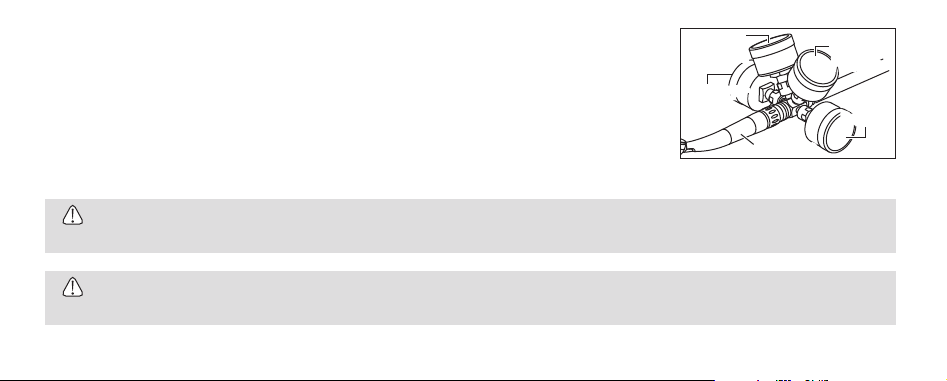
5. Connection & Disconnection of the Handpiece
Refer to Operation Manuals of coupling and hose before connecting the handpiece.
Z800L/Z800/Z900L/Z900
5-1 Connection
1) Insert the handpiece into the Coupling (Fig. 2).
2) Make sure the handpiece is firmly connected to the coupling.
5-2 Disconnection
Pull back the Retention Lock Ring and remove the handpiece from the Coupling (Fig. 2).
Handpiece Coupling
Retention Lock Ring
CAUTION
Ř Do not operate the Retention Lock Ring while under drive air pressure. The high pressure may cause sudden release of the handpiece from
the coupling.
6
Fig. 2
Page 8
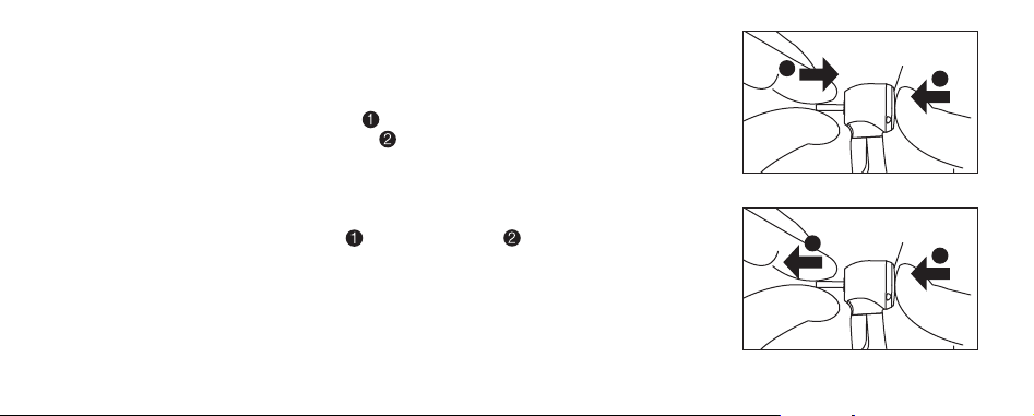
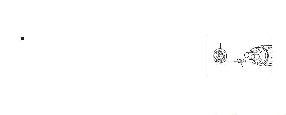
6. Insertion & Removal of the Bur
6-1 To Insert the Bur (Fig. 3)
1) Insert the bur into the chuck.
2) Depress the Push Button to open the chuck ( ).
3) Fully insert the bur into the chuck until it stops ( ) then release the Push Button.
4) Ensure that the bur is secure by gently pulling and pushing the bur WITHOUT depressing the Push Button.
6-2 To Remove the Bur (Fig. 4)
Depress the Push Button to open the chuck ( ) and remove the bur ( ).
EN DE FR ES IT PT
2
Push Button
1
Fig. 3
Push Button
2
1
Fig. 4
7
Page 9

NOTICE
Ř Grip the handpiece while placing your thumb tip on the Push button which makes it easier to depress the button.
CAUTION
Ř Always insert the bur all the way into the chuck.
Ř Remove the bur only after the handpiece has completely stopped rotating.
Ř Always keep the bur shank clean.
Ř Entry of debris into the chuck, via the bur shank, could cause bur rotation slip and also prevent the bur from being securely located in the
chuck.
Ř Do not exceed the bur speed recommended by the bur manufacturer.
Ř Do not exceed maximum bur length recommended by the handpiece manufacturer.
Ř Do not apply excess pressure to the bur as it may break or bend or become difficult to remove.
Ř DO NOT use burs with problems listed below as the bur may break, seize up or disengage from the chuck.
- Bent, deformed, anisomerous (worn), rusted, broken, deficient bur.
- Bur which is cracked on the edge or axis.
- Non-ISO standard, or tampered bur.
8
Page 10

7. Check before treatment
Check that the Head Cap is firmly tightened. Also check for handpiece vibration, noise and overheating outside the patient's oral cavity. If any
abnormalities are found do not use the handpiece and contact your Authorized NSK Dealer.
EN DE FR ES IT PT
9
Page 11
8. Maintenance
After each patient maintain the product as follows. Lack of maintenance could cause premature failure or
overheating of the handpiece.
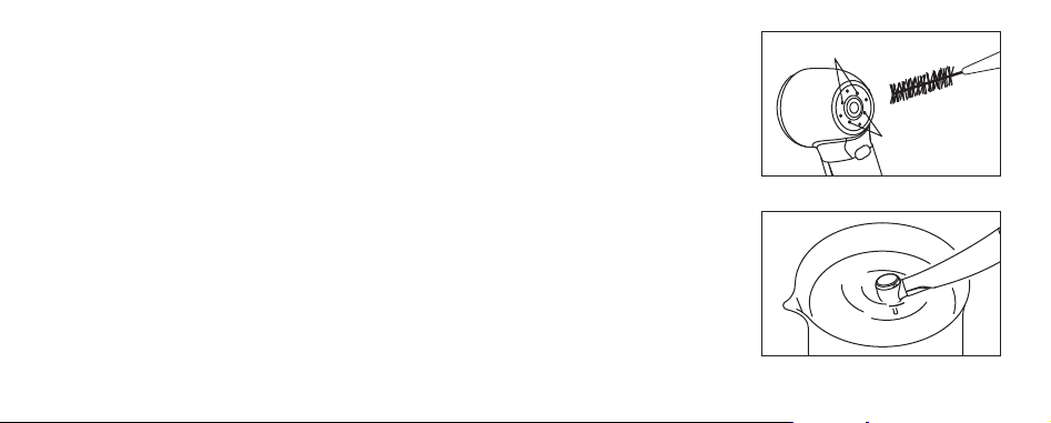
Clean Head Hole
8-1 Cleaning handpieces with the NSK Clean-Head System
After the treatment of each patient, clean the Clean Head.
1) Half fill a cup with clean water.
2) Remove dirt and debris from the Clean Head Holes with the cleaning wire and brush (supplied as an
accessory for the handpiece) (Fig. 5).
3) Rotate the handpiece and immerse half of the handpiece head in the cup of water (Fig. 6).
4) Rotate then stop intermittently the handpiece 3 times for 2 to 3 seconds each time.
5) Wipe the handpiece dry.
* If the dirt could not be removed from the hole, clean it by brush.
10
Clean Head Hole
Fig. 5
Fig. 6
Page 12

8-2 Cleaning (Handpiece)
1) Remove debris from the product. Do NOT use a wire brush.
2) Wipe clean with alcohol-immersed cotton swab or cloth.
This icon denotes that the product can be washed via Thermo Disinfector.
Refer to the Thermo-Disinfector manual.
CAUTION
Ř After washing with Thermo-Disinfector and prior to lubrication, dry the product until all internal moisture is thoroughly removed. Thermo-
Disinfector moisture remaining inside the product could reduce the effect of lubrication and could cause corrosion inside of the product.
Ř To clean the product never use any solvent such as benzine or thinner.
EN DE FR ES IT PT
11
Page 13
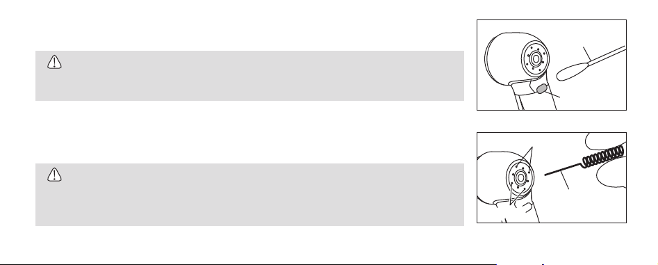
8-3 Cleaning (Optic)
Wipe clean the Glass Rod tip with an alcohol-immersed cotton swab. Remove all debris and oil (Fig. 7).
CAUTION
Ř Do NOT use a sharp tool to clean the Glass Rod. It could damage the glass and reduce the light
transmission.
8-4 Cleaning (Spray Port)
When spray ports are clogged, or spray does not exit evenly from the ports, clean the ports (Fig. 8).
CAUTION
Ř Do not forcibly insert the wire into the port. Resultant port damage could cause the spray to be
directed away from the bur, and the cooling efficiency reduces.
Ř Do not blow air into the Clean Head Hole.
12
Cotton Swab
Glass Rod
Fig. 7
Spray Port
Wire
Spray Port
Fig. 8
Page 14
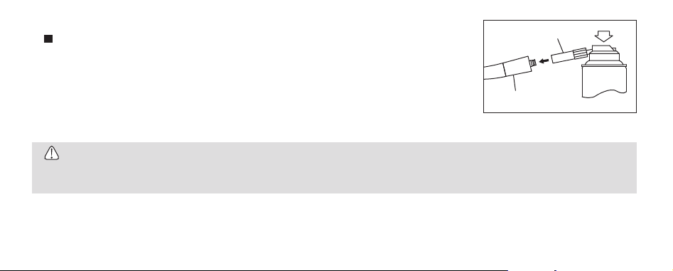
8-5 Lubrication
NSK PANA SPRAY Plus/PANA SPRAY
Apply NSK PANA SPRAY Plus/PANA SPRAY every time after each use and/or before autoclaving.
1) Remove the bur from the handpiece.
2) Insert the Spray Nozzle into the Spray Port nozzle on the can.
3) Insert the Spray Nozzle into the rear of the handpiece. Hold the handpiece and spray for approximately
2-3 seconds. Apply lubricant until it expels from the handpiece head for at least 2 seconds (Fig. 9)
.
Spray Nozzle
Handpiece
CAUTION
Ř When applying spray be sure to hold the handpiece firmly to prevent the handpiece from slipping out of the hand due to the spray pressure.
Ř Hold the spray can upright.
EN DE FR ES IT PT
Fig. 9
13
Page 15
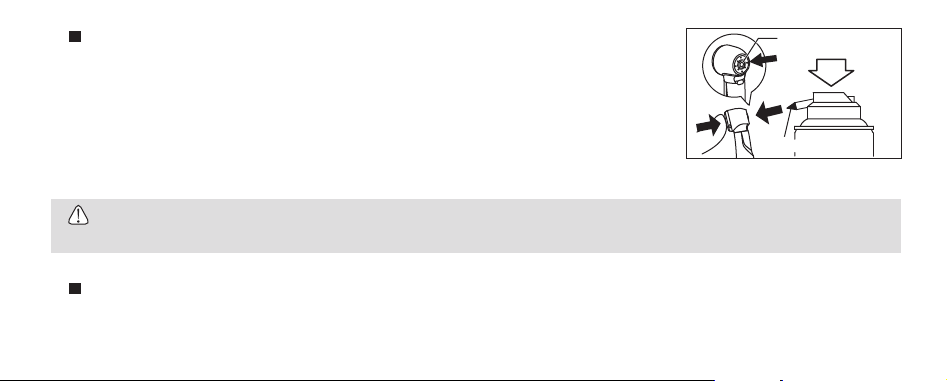
Chuck cleaning
Clean the Push Button chuck once a week.
1) Mount the Tip Nozzle into the spray can port.
2) Lubricate the chuck directly through the bur insertion hole (Fig. 10).
3) Lubricate handpiece by using NSK PANA SPRAY Plus/PANA SPRAY (Fig. 9) or NSK automatic handpiece
cleaning and lubrication system.
CAUTION
Ř If
the chuck is not regularly cleaned the chuck grip may be weakened and the bur may be accidentally released while in operation.
NSK automatic handpiece cleaning and lubrication system
When using NSK automatic handpiece cleaning and lubrication system, refer to the system instructions.
14
Bur Insertion Hole
Tip Nozzle
Fig. 10
Page 16

8-6 Sterilization
Sterilize the product by autoclave sterilization. Remove the bur after each patient and sterilize as noted below.
1) Insert into an autoclave pouch. Seal the pouch.
2) Autoclavable under the conditions below.
Autoclave for more than 20 min. at 121°C, or 15 min. at 132°C, or 3 min. at 134°C.
3) The handpiece should remain in the autoclave pouch until required for use.
CAUTION
ŘDo not autoclave the product with other instruments even when it is in a pouch. This is to prevent possible discoloration and damage to the
product from chemical residue on other instruments.
ŘKeep the product in suitable atmospheric pressure, temperature, humidity, ventilation, and sunlight. The air should be free from dust, salt and
sulphur.
ŘImmediately after use, the product should be cleaned, lubricated and sterilized. If blood remains on the external or internal surfaces it can
become clotted and cause rust.
ŘDo not heat or cool the product too quickly. Rapid change in temperature could cause damage to the product.
ŘIf the sterilizer chamber temperature may exceed 135°C during the dry cycle then delete the dry cycle.
EN DE FR ES IT PT
15
Page 17

CAUTION
Ř Autoclave sterilization is recommended for the product. The validity of other sterilization methods is not confirmed.
Ř Do not touch the product immediately after autoclaving as it will be very hot and must remain in a sterile condition.
NOTICE
Ř NSK recommends Class B sterilizers as stated in EN13060.
16
Page 18
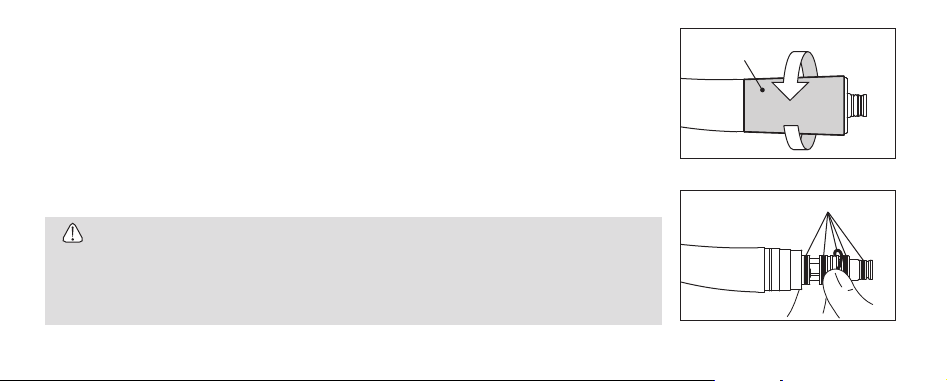
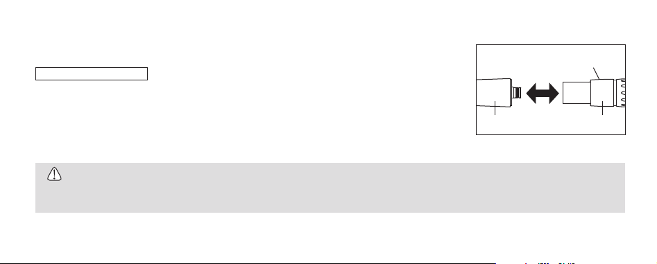
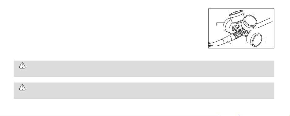
9. Replacing the O-rings
Replace the O-rings if water is present in the exhaust air line. This is an indication of possible water leakage
within the coupling. ALWAYS change the complete set of O-rings.
1) Loosen and remove the taper ring at the rear of the handpiece (Fig. 11).
2) Gently remove each O-ring by hand (Fig. 12).
3) Insert the complete set of new O-rings in the correct grooves.
4) Firmly tighten the taper rin
* Refer to Spare Parts List to identify the correct parts.
(Z800L/Z800/Z900L/Z900)
g.
CAUTION
Ř Do not force the new replacement O-ring with excessive pressure.
Ř When inserting new O-rings, make sure they are inserted in the correct grooves.
Ř Make certain that the taper ring is firmly tightened. If the taper ring is loose water and air leakage
could occur.
Taper Ring
O-ring
EN DE FR ES IT PT
Fig. 11
Fig. 12
17
Page 19
10. Replacing the Non-Retraction Valve
A water Non-Retraction Valve is integrated in the Coupling Joint, which shuts off the water retraction directly at the handpiece head to prevent fluids
infiltrating the water line. If water is beginning to leak from the handpiece, replace the non-retraction valve.
NSK Coupling (Z800L/Z800/Z900L/Z900)
1) Remove the Coupling Joint from the hose.
2) Remove the back-end Gasket.
3) Pull and remove the water tube, and remove the Non-Retraction Valve.
4) Insert the new Non-Retraction Valve securely and remount the back-end Gasket.
* Refer to Spare Parts List to identify the correct parts.
18
Back-end Gasket
Non-Retraction Valve
Fig. 13
Page 20

11. Periodical Maintenance Checks
Perform periodical maintenance checks every three months, referring to the check sheet below. If any abnormalities are found, contact your Authorized
NSK Dealer.
Points to check Details
Head cap is loose Check that the Head Cap is firmly tightened.
Rotation Rotate the handpiece and check for abnormalities such as abnormal rotation, vibration, noise, and overheating.
Coolant Water Operate the handpiece and check that the coolant water is flowing through all spray ports.
12. Symbol
This product is Autoclavable up to Max.135ºC. This product can be washed via Thermo Disinfector.
Conforms to CE European Directive of "Medical device directive 93/42/EEC".
Manufacturer.
Authorized representative in the European community.
Caution: U.S. Federal law restricts this device to sale by or on the order of a licensed physician.
GS1 DataMatrix for Unique Device Identifier.
EN DE FR ES IT PT
19
Page 21

13. Warranty
NSK products are warranted against manufacturing errors and defects in materials. NSK reserves the right to analyze and determine the cause of any
problem. Warranty is voided should the product be not used correctly or for the intended purpose or has been tampered with by unqualified personnel
or has had non NSK parts installed. Replacement parts are available for seven years beyond discontinuation of the model.
14. Option Parts List
MG-4H Multi Gauge Z109400
MG-2/3H Multi Gauge Z109200
20
Model Order Code
Page 22

15. Spare Parts List
Model Order Code Compatible Product Remarks
PTL O-ring Set Y900580 Z800L/Z800/Z900L/Z900 Non-Retraction Valve P401054 NSK coupling Cleaning Wire Z144095 - -
* For other parts contact your Authorized NSK Dealer.
16. Disposing product
In order to avoid the health risks of operators handling the disposal of medical equipment, as well as the risks of environmental contamination caused
thereof, a surgeon or a dentist is required to confirm the equipment is sterile. Ask specialist firms who are licensed to dispose of specially controlled
industrial wastes, to dispose the product for you.
EN DE FR ES IT PT
21
Page 23

17. Specifications
Model Z800L Z800 Z800KL Z800K Z800SL Z800BL Z800WL Z800W Z800WHL Z800MWL Z800STL
Rotation Speed 360,000 - 440,000min-1 (at the recommended drive air pressure)
Bur Type ISO 1797-1 Ø1.59 - 1.60mm Short Shank Bur/Standard Bur
Chucking Length 10mm
Max. Bur Length 21mm
Max. Working Part Diameter Ø2mm
Recommended Drive Air Pressure 0.28MPa (2.8kgf/cm
Operating Drive Air Pressure Range 0.25 - 0.30MPa (2.5 - 3.0kgf/cm2)
Max. Air Consumption <66NL/min (0.3MPa)
Water Pressure 0.08 - 0.20MPa (0.8 - 2.0kgf/cm
Chip Air Pressure 0.10 - 0.20MPa (1.0 - 2.0kgf/cm2)
Optic
Glass Rod - Glass Rod - Glass Rod White LED - Glass Rod
Voltage - AC/DC 3.3±0.05V Active Voltage - 2.8 - 4.0V Consumption Current -
0.38A Typical (3.3V)
Use Environment Temperature: 10 - 40°C (No Condensation), Humidity: 30 - 75%
Transportation and Store Environment Temperature: -10 - 50°C, Humidity: 10 - 85%, Atmospheric Pressure: 500 - 1,060hPa
22
2
)
2
)
-
Page 24

Model Z900L Z900 Z900KL Z900K Z900SL Z900BL Z900WL Z900W Z900WHL Z900MWL Z900STL
Rotation Speed 320,000 - 400,000min-1 (at the recommended drive air pressure)
Bur Type ISO 1797-1 Ø1.59 - 1.60mm Standard Bur
Chucking Length 12mm
Max. Bur Length 21mm
Max. Working Part Diameter Ø2mm
Recommended Drive Air Pressure 0.28MPa (2.8kgf/cm
2
)
Operating Drive Air Pressure Range 0.25 - 0.30MPa (2.5 - 3.0kgf/cm2)
Max. Air Consumption <66NL/min (0.3MPa)
Water Pressure 0.08 - 0.20MPa (0.8 - 2.0kgf/cm2)
Chip Air Pressure 0.10 - 0.20MPa (1.0 - 2.0kgf/cm2)
Optic
Glass Rod - Glass Rod - Glass Rod White LED - Glass Rod
Voltage - AC/DC 3.3±0.05V Active Voltage - 2.8 - 4.0V Consumption Current -
0.38A Typical (3.3V)
Use Environment Temperature: 10 - 40°C (No Condensation), Humidity: 30 - 75%
Transportation and Store Environment Temperature: -10 - 50°C, Humidity: 10 - 85%, Atmospheric Pressure: 500 - 1,060hPa
* Available models differ according to countries/regions.
EN DE FR ES IT PT
23
Page 25

Z800L/Z800/Z900L/Z900 For NSK Phatelus/Mach Coupling
Z800KL/Z800K/Z900KL/Z900K For KaVo® MULTIflex®, MULTIflex® LUX Coupling KaVo® and MULTIflex® are registered trademarks of Kaltenbach & Voigt GmbH & Co., Germany.
Z800SL/Z900SL For Sirona® Quick Coupling Sirona® is a registered trademark of Sirona Dental Systems GmbH, Germany.
Z800BL/Z900BL For Bien-Air® Unifix®, Unifix® L Coupling Bien-Air® and Unifix® are registered trademarks of Bien-Air Dental S.A.,Switzerland.
Z800WL/Z800W/Z900WL/Z900W For W&H® Roto Quick® Coupling W&H® and Roto Quick® are registered trademarks of W&H Dentalwerk Bürmoos GmbH, Austria.
Z800WHL/Z900WHL For adec RA-24, RA-25Roto Quick
Z800MWL/Z900MWL Morita 4H-type Joint
Z800STL/Z900STL For 360° HiFlo® Quick-Connect Swivel HiFlo® is a registered trademark of DentalEZ., United States of America.
®
Coupling Roto Quick® is a registered trademark of W&H Dentalwerk Bürmoos GmbH, Austria.
24
Page 26

1. Benutzer und Verwendungszweck
Benutzer: Qualifiziertes Fachpersonal
Verwendungszweck: Zahnmedizinische Behandlung
2. Sicherheitsanweisungen für die Handhabung und Bedienung
Lesen Sie bitte diese Sicherheitsanweisungen aufmerksam durch und benutzen Sie das Gerät ausschließlich gemäß seines bestimmungsgemäßen
Gebrauchs und entsprechend der Anweisungen.
Die Sicherheitsanweisungen sind dafür vorgesehen, mögliche Gefahren zu verhindern, die Körperverletzungen oder Beschädigungen am Gerät
verursachen können.
Die Sicherheitsanweisungen werden gemäß der Schwere des Risikos wie folgt klassifiziert.
KLASSE Ausmaß und Schwere der Gefährdung oder Schädigung
ACHTUNG
VORSICHT
HINWEIS
Risiko, das zu schweren Verletzungen oder Schäden am Gerät führen kann, wenn die Sicherheitshinweise nicht beachtet werden.
Ein mögliches Risiko, das zu leichten bis mittleren Personen- oder Sachschäden führen kann, wenn die Sicherheitshinweise
nicht beachtet werden.
Allgemeine Produktinformationen, die besonders hervorgehoben werden, um Störungen oder Leistungsminderungen zu vermeiden.
DEUTSCH
25
Page 27

ACHTUNG
ŘDas Drücken des Druckknopfes bei Rotation des Instruments führt zu einer ÜBERHITZUNG des Spannfuttermechanismus. Bei der Arbeit ist
besonders darauf zu achten, Wangengewebe vom Druckknopf fernzuhalten. Ein Kontakt mit dem Wangengewebe kann dazu führen, dass der
Druckknopf betätigt wird und der Patient verletzt wird.
VORSICHT
ŘLesen Sie diese Betriebsanleitung vor dem Gebrauch sorgfältig durch und machen Sie sich mit allen Bedienungsfunktionen vertraut. Bewahren
Sie die Betriebsanleitung so auf, dass sie für die zukünftige Verwendung leicht auffindbar ist.
ŘBerücksichtigen Sie beim Betrieb des Produkts immer die Sicherheit des Patienten.
ŘDer Benutzer ist für die Funktionsprüfung, Wartung und ständige Überprüfung dieses Produkts verantwortlich.
ŘVersuchen Sie nicht, das Produkt auseinander zu bauen, und nehmen Sie keine Änderungen am Mechanismus vor, es sei denn, dies wird von
NSK in diesem Handbuch empfohlen.
ŘSchützen Sie das Produkt vor Stößen. Lassen Sie das Produkt nicht fallen.
ŘBediener und alle anderen Personen in der Umgebung müssen während der Benutzung dieses Handstücks einen Augenschutz tragen.
ŘSollte das Produkt nicht einwandfrei funktionieren, stellen Sie den Einsatz sofort ein und nehmen Sie Kontakt mit Ihrem NSK-Fachhändler auf.
26
Page 28

VORSICHT
ŘBenutzen Sie kein Wasser mit hohem Säuregehalt oder Sterilisationslösungen zum Abwischen, Eintauchen oder Reinigen des Produkts. Legen
Sie das Produkt nicht in solche ein.
ŘDie Produkte werden im unsterilen Zustand ausgeliefert und müssen vor dem Gebrauch autoklaviert werden.
ŘFühren Sie in regelmäßigen Abständen Funktionsprüfungen und Wartungen durch.
ŘWenn das Produkt längere Zeit nicht benutzt wurde, müssen Sie zunächst prüfen, ob es einwandfrei funktioniert, bevor Sie es am Patienten
anwenden.
ŘEs wird empfohlen, ein Reservegerät für den Fall eines Ausfalls während einer Operation verfügbar zu haben.
ŘSchauen Sie nicht direkt in das LED-Licht (Z800BL/Z800WL/Z900BL/Z900WL).
ŘDieses Instrument ist ein LED-Produkt, welches gemäß EN62471 klassifiziert ist in der "Befreiten Gruppe" (keine photobiologische Gefährung)
(Z800BL/Z800WL/Z900BL/Z900WL).
ŘBenutzen Sie eine Stromquelle, die die folgenden Anforderungen erfüllt (Z800BL/Z800WL/Z900BL/Z900WL).
1. Die Stromversorgung der Stromquelle liegt sowohl unter normalen Bedingungen als auch im Fehlerfall unter 15W.
2. Die Stromquelle verwendet einen SELV-Kreis für die Stromversorgung.
3. Die Ausgangsspannung der Stromquelle befindet sich innerhalb des vom Hersteller dieses Produkts empfohlenen Bereichs.
ŘEin U.S. Bundesgesetz schreibt vor, dass dieses Produkt nur durch einen oder im Auftrag eines lizenzierten Mediziners verkauft werden darf.
EN DE FR ES IT PT
27
Page 29

3. Zubehörteile-Liste
Nr. Bezeichnung der Teile Anzahl Bemerkungen
1 Sprühdüse 1 2 Reinigungsdraht 1 Set bestehend aus Bürstchen und Reinigungsdraht
3 PTL O-Ring-Satz 1 In den Sets von Z800L/Z800/Z900L/Z900 enthalten
28
Page 30
4. Einstellung des Luft- & Wasserdrucks
Messen Sie den Versorgungsdruck am Handstück/Schlauchanschluss und stellen Sie den Druck entsprechend
den Angaben in der Tabelle ein (Abb. 1).
Für Informationen zu Multi Gauge siehe Stückliste.
WARNUNG
ŘÜberschreiten Sie nicht den in der Tabelle genannten optimalen Druck.
VORSICHT
ŘBenutzen Sie keine durch Staub, Feuchtigkeit und Öl verunreinigte Luft.
SprayluftDruck
RückluftDruck
EN DE FR ES IT PT
Wasserdruck
Antriebsluft-
Druck
Handstück
Abb. 1
29
Page 31

5. Verbinden & Abtrennen des Handstücks
Beachten Sie die Betriebsanleitungen der Kupplung und des Schlauchs, bevor Sie das Handstück montieren.
Z800L/Z800/Z900L/Z900
5-1 Montage
1) Führen Sie Handstück und Kupplung zusammen (Abb. 2).
2) Stellen Sie sicher, dass das Handstück fest mit der Kupplung verbunden ist.
5-2 Demontage
Ziehen Sie am Haltering und entfernen Sie das Handstück aus der Kupplung (Abb. 2).
Handstück Kupplung
VORSICHT
ŘBetätigen Sie den Haltering nicht unter Druck. Der hohe Druck kann zu einem plötzlichen Lösen des Handstücks von der Kupplung führen.
30
Haltering
Abb. 2
Page 32

6. Einsetzen & Entfernen des Fräsers oder Schleifers
6-1 Einsetzen des Fräsers oder Schleifers ("Bohrers") (Abb. 3)
1) Führen Sie den Bohrer in die Spannzange ein.
2) Betätigen Sie den Druckknopf, um die Spannzange zu öffnen ( ).
3) Führen Sie den Bohrer vollständig in die Spannzange ein ( ) und lassen Sie den Druckknopf los.
4) Stellen Sie sicher, dass die Fräse festsitzt, indem Sie vorsichtig daran ziehen und drücken, OHNE dabei
den Druckknopf zu betätigen.
EN DE FR ES IT PT
2
Druckknopf
1
Abb. 3
6-2 Entfernen des Fräsers oder Schleifers (Abb. 4)
Betätigen Sie den Druckknopf ( ) und entnehmen Sie den Bohrer aus der Spannzange ( ).
Druckknopf
2
1
Abb. 4
31
Page 33

HINWEIS
ŘGreifen Sie das Handstück, indem Sie das Handstück mit dem Zeigefinger im vorderen Halsbereich fixieren. Dies erleichtert die Betätigung des
Druckknopfs mit dem Daumen.
VORSICHT
ŘFühren Sie den Fräser/Schleifer immer komplett in das Spannfutter ein.
ŘEntfernen Sie den Fräser/Schleifer erst, wenn das Handstück vollständig zum Stillstand gekommen ist.
ŘHalten Sie den Schaft des Fräsers/Schleifers stets sauber.
ŘDas Eindringen von Fremdkörpern in das Spannfutter über den Fräserschaft kann zu Schlupf führen und verhindern, dass sich der Fräser/
Schleifer fest ins Spannfutter einspannen lässt.
ŘÜberschreiten Sie nicht die vom Hersteller des Fräsers/Schleifers angegebene Drehzahl.
ŘÜberschreiten Sie nicht die von NSK empfohlene maximale Fräser-/Schleiferlänge.
ŘWenden Sie keinen übermäßigen Druck auf den Fräser/Schleifer an, da dieser brechen oder sich verbiegen kann oder nur schwer zu entfernen
sein wird.
32
Page 34

VORSICHT
ŘVerwenden Sie KEINE Bohrer, die eines der im Folgenden aufgeführten Probleme aufweisen, da diese ansonsten brechen, sich in der
Spannzange verhaken oder sich aus dieser lösen können.
- Verbogener, verformter, anisomerer (verschlissener), verrosteter, beschädigter, mangelhafter Fräser/Schleifer.
- Fräser mit einem Riss in der Kante oder in einer Achse.
- Fräser, der nicht der ISO-Norm entspricht oder in irgendeiner Weise verändert wurde.
7. Überprüfung vor der Behandlung
Überprüfen Sie, ob der Kopfdeckel fest angezogen ist. Überprüfen Sie das Handstück zudem auf Vibrationen, Geräusche und Überhitzung außerhalb
der Mundöffnung des Patienten. Wenn Sie irgendwelche Auffälligkeiten feststellen, darf das Handstück nicht benutzt werden. Nehmen Sie in diesem
Fall Kontakt mit Ihrem NSK-Fachhändler auf.
EN DE FR ES IT PT
33
Page 35

8. Wartung
Führen Sie nach jedem Patienten die folgende Wartung des Produkts durch. Eine unzureichende Wartung
könnte zu einem vorzeitigen Ausfall oder zur Überhitzung des Handstücks führen.
Clean Head-Öffnung
8-1 Reinigung von Handstücken mit dem Clean-Head-System von NSK
Reinigen Sie das Clean Head-System nach jeder Behandlung.
1) Füllen Sie einen Becher halbvoll mit klarem Wasser.
2) Entfernen Sie mit dem Reinigungsdraht und der Bürste (als Zubehör zum Handstück mitgeliefert) Schmutz
und Ablagerungen aus den Clean Head-Öffnungen (Abb. 5).
3) Drehen Sie das Handstück und tauchen Sie den Handstückkopf halb in den Becher mit Wasser ein (Abb. 6).
4) Lassen Sie das Handstück drei Mal ca. 2 bis 3 Sekunden lang im Wasser abwechselnd laufen und
stoppen.
5) Wischen Sie das Handstück trocken.
* Wenn der Schmutz sich nicht aus der Öffnung entfernen lässt, reinigen Sie ihn mit der Bürste.
34
Clean HeadÖffnung
Abb. 5
Abb. 6
Page 36

8-2 Reinigung (Handstück)
1) Entfernen Sie Schmutz und Ablagerungen vom Produkt. Benutzen Sie keine Drahtbürste.
2) Wischen Sie es mit einem in Alkohol getränkten Wattestäbchen oder Tuch sauber.
Dieses Symbol bedeutet, dass das Produkt mittels Thermodesinfektor gereinigt werden kann.
Beachten Sie die Bedienungsanleitung des Thermodesinfektors.
VORSICHT
ŘLassen Sie das Produkt nach der Reinigung mittels Thermodesinfektor und vor der Schmierung trocknen, bis die gesamte Feuchtigkeit im
Inneren entwichen ist. Feuchtigkeit des Thermodesinfektors im Inneren des Produkts kann die Wirkung der Schmierung verringern und
Korrosion im Inneren des Produkts verursachen.
ŘBenutzen Sie für die Reinigung des Produkts niemals Lösungsmittel wie Verdünner oder Benzin.
EN DE FR ES IT PT
35
Page 37

8-3 Reinigung (Glasstab-Lichtleiter)
Wischen Sie die Spitze des Glasstabs mit einem in Alkohol getränkten Wattestäbchen ab. Entfernen Sie
sämtliche Ablagerungen und Ölrückstände (Abb. 7).
VORSICHT
ŘBenutzen Sie keine scharfen Gegenstände für die Reinigung des Glasstabs. Diese können das Glas
beschädigen und die Lichtübertragung beeinträchtigen.
8-4 Reinigung (Sprayöffnung)
Wenn die Sprayöffnungen verstopft sind oder die Düsen nicht gleichmäßig sprühen, sind die Öffnungen zu
reinigen (Abb. 8).
Wattestäbchen
Glasstab
Abb. 7
Sprayöffnung
VORSICHT
ŘBeim Einführen des Drahtes in die Öffnung sollten Sie keinen zu starken Druck ausüben. Eine
beschädigte Öffnung kann bewirken, dass die Sprayrichtung verändert wird und das Kühlspray nicht
mehr den Bohrer trifft, woraus eine Abnahme der Kühleffizienz erfolgt.
ŘBlasen Sie keine Luft durch die Clean Head-Öffnung.
36
Draht
Sprühöffnung
Abb. 8
Page 38

8-5 Schmierung
NSK PANA SPRAY Plus
Führen Sie nach jeder Benutzung und/oder vor der Autoklavierung eine Ölpflege mit NSK PANA SPRAY Plus
durch.
1) Entfernen Sie den Bohrer vom Handstück.
2) Führen Sie die Sprühdüse in die Sprühöffnung an der Dose ein.
3) Setzen Sie die Sprühdüse auf der Rückseite des Handstücks ein. Halten Sie das Handstück fest und
sprühen Sie für die Dauer von etwa 2-3 Sekunden. Tragen Sie Schmiermittel auf, bis es mindestens 2
Sekunden lang aus dem Handstückkopf austritt (Abb. 9).
Sprühdüse
Handstück
VORSICHT
ŘStellen Sie beim Anwenden des Spray sicher, dass Sie das Handstück festhalten, um zu verhindern, dass das Handstück bei der Schmierung
aufgrund des Spray-Drucks herausrutscht.
ŘHalten Sie die Dose aufrecht.
EN DE FR ES IT PT
Abb. 9
37
Page 39

Reinigung der Spannzange
Reinigen Sie die Druckknopf-Spannzange einmal pro Woche.
1) Montieren Sie die Öl-Sprühdüse (Spannzange; blau) auf der Spraydose.
2) Schmieren Sie die Spannvorrichtung direkt durch die Spannzangenöffnung (Abb. 10).
3) Schmieren Sie das Handstück mit NSK PANA SPRAY Plus (Abb. 9) oder mit dem automatischen
Pflegegerät von NSK.
VORSICHT
ŘWenn die Spannzange nicht regelmäßig gereinigt wird, treten Abnutzungserscheinungen am
Spannfutterhalter auf, wodurch sich der Bohrer während des Betriebs versehentlich lösen kann.
38
Spannzangenöffnung
Öl-Sprühdüse blau
Abb. 10
Page 40

Automatisches NSK Pflegegerät
Bitte beachten Sie für die Verwendung des automatischen Pflegegeräts von NSK die jew. Gebrauchsanweisung des Gerätes.
8-6 Sterilisation
Sterilisieren Sie das Produkt im Autoklaven. Entfernen Sie den Bohrer nach jedem Patienten und sterilisieren Sie es wie unten beschrieben.
1) Legen Sie das Gerät in einen Sterilisations-Beutel. Versiegeln Sie diesen.
2) Autoklavierbar unter den unten genannten Bedingungen.
Autoklavierbar für mehr als 20 Min. bei 121°C, oder 15 Min. bei 132°C, oder 3 Min. bei 134°C.
3) Das Handstück sollte bis zum Gebrauch im Sterilisations-Beutel verbleiben.
EN DE FR ES IT PT
39
Page 41

VORSICHT
ŘAutoklavieren Sie das Produkt nicht mit anderen Instrumenten, auch dann nicht, wenn es sich in einem Beutel befindet. Dadurch wird eine
mögliche Verfärbung und Beschädigung des Produkts durch chemische Rückstände auf anderen Instrumenten vermieden.
ŘLagern Sie das Produkt unter geeigneten Verhältnissen hinsichtlich Luftdruck, Temperatur, Luftfeuchtigkeit, Belüftung und Sonneneinstrahlung.
Die Luft darf nicht staub-, salz- oder schwefelhaltig sein.
ŘDas Produkt sollte unmittelbar nach dem Einsatz gereinigt, geschmiert und sterilisiert werden. Wenn innen oder außen Blut zurückbleibt, kann
es gerinnen und Rost oder sonstige Schäden verursachen.
ŘProdukt nicht zu schnell erhitzen oder abkühlen. Ein schneller Temperaturwechsel kann das Produkt beschädigen.
ŘFalls die Sterilisationskammer während der Trocknung 135°C überschreiten kann, überspringen Sie den Trocknungszyklus.
ŘFür das Produkt wird eine Autoklavsterilisation empfohlen. Die Wirksamkeit anderer Sterilisierungsverfahren kann nicht bestätigt werden.
ŘBerühren Sie das Produkt nicht sofort nach dem Autoklavieren, da es sehr heiß ist und steril bleiben soll.
HINWEIS
ŘNSK empfiehlt Klasse B-Sterilisation nach EN13060.
40
Page 42

9. Austausch der O-Ringe
Tauschen Sie die O-Ringe aus, falls Wasser in der Rückluftleitung vorhanden ist. Dies lässt auf ein mögliches
Wasserleck innerhalb der Kupplung schließen. Tauschen Sie IMMER den kompletten Satz O-Ringe aus.
1) Lösen und entfernen Sie die Kupplungshülse hinten am Handstück (Abb. 11).
2) Entfernen Sie vorsichtig von Hand alle O-Ringe (Abb. 12).
3) Setzen Sie einen kompletten Satz neuer O-Ringe in die richtigen Fräsungen ein.
4) Montieren Sie die Kupplungshülse und ziehen Sie sie sicher fest.
* Sh. Ersatzteilliste zur Auswahl der korrekten Teile.
(Z800L/Z800/Z900L/Z900)
VORSICHT
ŘWenden Sie beim Einsetzen der neuen O-Ringe keinen übermäßigen Druck an.
ŘStellen Sie sicher, dass die O-Ringe in die richtigen Fräsungen eingesetzt werden.
ŘStellen Sie sicher, dass die Kupplungshülse sicher festgezogen ist. Bei locker sitzender
Kupplungshülse können Wasser- und Luftundichtigkeiten auftreten.
Kupplungshülse
O-ring
Abb. 11
Abb. 12
EN DE FR ES IT PT
41
Page 43

10. Austausch des Rückschlagventils
In der Kupplungsdichtung ist ein Rückschlagventil eingebaut, das den Wasserrückfluss direkt am Handstückkopf abwehrt. Damit wird vermieden, dass
Flüssigkeit in die Wasserleitung zurück gesaugt wird. Wenn Wasser aus dem Handstück austritt, ersetzen Sie das Rückschlagventil.
NSK-Kupplung (Z800L/Z800/Z900L/Z900)
1) Entfernen Sie die Kupplungsdichtung vom Schlauch.
2) Entfernen Sie die hintere Dichtung.
3) Ziehen Sie die Wasserleitung ab und entfernen Sie das Rückschlagventil.
4) Stecken Sie das neue Rückschlagventil fest ein und befestigen Sie wieder die Dichtung am hinteren Ende.
* Sh. Ersatzteilliste zur Auswahl der korrekten Teile.
42
Hintere Dichtung
Rückschlagventil
Abb. 13
Page 44

11. Regelmäßige Wartungsprüfungen
Führen Sie alle drei Monate Wartungsprüfungen durch, siehe dazu die im Folgenden aufgeführten Kontrollpunkte. Wenn Sie irgendeine Auffälligkeit
feststellen, nehmen Sie Kontakt mit Ihrem NSK-Fachhändler auf.
Prüfpunkte Beschreibung
Kopfdeckel ist locker Überprüfen Sie, ob der Kopfdeckel fest angezogen ist.
Rotation
Kühlwasser Setzen Sie das Handstück in Betrieb und überprüfen Sie, ob das Kühlwasser durch alle Sprayöffnungen austritt.
Lassen Sie das Handstück laufen und überprüfen Sie es auf Auffälligkeiten z.B. ungewöhnliche Laufeigenschaften,
Vibration, Geräusche und Überhitzung.
12. Symbol
Dieses Produkt kann bei bis zu max.135ºC. autoklaviert werden.
Dieses Produkt kann mit einem Thermodesinfektor gereinigt und desinfiziert werden.
Die EU-Richtlinie 93/42/EEC wurde bei der Entwicklung und Herstellung dieses medizinischen Gerätes angewendet.
Hersteller.
EN DE FR ES IT PT
43
Page 45

Autorisierter Repräsentant in der Europäischen Gemeinschaf.
Vorsicht: Ein U.S. Bundesgesetz schreibt vor, dass dieses Produkt nur durch einen oder im Auftrag eines lizenzierten Mediziners verkauft
werden darf.
GS1 DataMatrix für Unique Device Identifier (UDI-Produktkennzeichnungssystem).
13. Garantie
Für alle NSK-Produkte gilt eine Garantie für Fabrikationsfehler und Mängel an Materialien. NSK behält sich das Recht vor, die Ursache von Problemen
zu analysieren und zu ermitteln. Die Garantie erlischt, wenn das Produkt nicht ordnungsgemäß oder nicht sachgemäß verwendet wurde, das Produkt
von unqualifiziertem Personal verändert wurde oder Fremdteile (Nicht-NSK-Teile) eingebaut wurden. Ersatzteile sind bis mindestens sieben Jahre nach
Einstellung der Produktion des Modells erhältlich.
14. Stückliste
MG-4H Multi Gauge Z109400
MG-2/3H Multi Gauge Z109200
44
Modell Bestellnummer
Page 46

15. Ersatzteilliste
PTL O-Ring-Satz Y900580 Z800L/Z800/Z900L/Z900 -
Modell Bestellnummer
Rückschlagventil P401054 NSK-Kupplung Reinigungsdraht Z144095 - -
* Kontaktieren Sie Ihren autorisierten Fachhändler für sonstige Ersatzteile.
kompatibel mit folgendem/n Produkt/en
Bemerkungen
16. Entsorgung des Produkts
Zur Vermeidung von Risiken der Gesundheit des Benutzers bei der Entsorgung der medizinischen Ausrüstung sowie des Risikos der Umweltverschmutzung
durch die Entsorgung der medizinischen Ausrüstung muss ein Chirurg oder ein Zahnarzt bestätigen, dass die Ausrüstung steril ist. Beauftragen Sie eine
Fachfirma, die über eine Zulassung zur Entsorgung von speziell kontrollierten industriellen Abfällen verfügt, mit der Entsorgung des Produkts.
EN DE FR ES IT PT
45
Page 47

17. Technische Daten
Modell Z800L Z800 Z800KL Z800K Z800SL Z800BL Z800WL Z800W Z800WHL Z800MWL Z800STL
Drehzahl 360.000 - 440.000min-1 (bei empfohlenem Antriebsdruck)
Fräser-/Schleifertyp ISO 1797-1 Ø1,59 - 1,60mm Fräse mit kurzem Schaft/Standard-Fräse
Schaftlänge 10mm
Max. Fräserlänge 21mm
Max. Arbeitsteil-Durchmesser Ø2mm
Empfohlener Antriebsdruck 0,28MPa (2,8bar)
Antriebsdruck-Bandbreite 0,25 - 0,30MPa (2,5 - 3,0bar)
Max. Luftverbrauch <66NL/min (0,3MPa)
Wasserdruck 0,08 - 0,20MPa (0,8 - 2,0bar)
Luftdruck 0,10 - 0,20MPa (1,0 - 2,0bar)
Licht
Spannung - AC/DC 3,3±0,05V Aktive Spannung - 2,8 - 4,0V Verbrauchsstrom Benutzungsumgebung Temperatur: 10 - 40°C (Keine Kondensation), Luftfeuchtigkeit: 30 - 75%
Transport und Lagerort Temperatur: -10 - 50°C, Luftfeuchtigkeit: 10 - 85%, Atmosphärischer Druck: 500 - 1.060hPa
46
Glasstab - Glasstab - Glasstab weiße LED - Glasstab
0,38A typisch (3,3V)
-
Page 48

Modell Z900L Z900 Z900KL Z900K Z900SL Z900BL Z900WL Z900W Z900WHL Z900MWL Z900STL
Drehzahl 320.000 - 400.000min-1 (bei empfohlenem Antriebsdruck)
Fräser-/Schleifertyp ISO 1797-1 Ø1,59 - 1,60mm Standard-Fräse
Schaftlänge 12mm
Max. Fräserlänge 21mm
Max. Arbeitsteil-Durchmesser Ø2mm
Empfohlener Antriebsdruck 0,28MPa (2,8bar)
Antriebsdruck-Bandbreite 0,25 - 0,30MPa(2,5 - 3,0bar)
Max. Luftverbrauch <66NL/min (0,3MPa)
Wasserdruck 0,08 - 0,20MPa (0,8 - 2,0bar)
Luftdruck 0,10 - 0,20MPa (1,0 - 2,0bar)
Licht
Glasstab - Glasstab - Glasstab weiße LED - Glasstab
Spannung - AC/DC 3,3±0,05V Aktive Spannung - 2,8 - 4,0V Verbrauchsstrom -
0,38A typisch (3,3V)
Benutzungsumgebung Temperatur: 10 - 40°C (Keine Kondensation), Luftfeuchtigkeit: 30 - 75%
Transport und Lagerort Temperatur: -10 - 50°C, Luftfeuchtigkeit: 10 - 85%, Atmosphärischer Druck: 500 - 1.060hPa
* verfügbare Modelle können je nach Land unterschiedlich sein.
EN DE FR ES IT PT
47
Page 49

Z800L/Z800/Z900L/Z900 Für NSK Phatelus/Mach Kupplung
Z800KL/Z800K/Z900KL/Z900K Für KaVo® MULTIflex®, MULTIflex® LUX Kupplung KaVo® und MULTIflex® sind eingetragene Marken von Kaltenbach & Voigt GmbH & Co., Deutschland.
Z800SL/Z900SL Für Sirona® Schnellkupplung Sirona® ist eine eingetragene Marke von Sirona Dental Systems GmbH, Deutschland.
Z800BL/Z900BL Für Bien-Air® Unifix®, Unifix® L Kupplung Bien-Air® und Unifix® sind eingetragene Marken von Bien-Air Dental S.A., Schweiz.
Z800WL/Z800W/Z900WL/Z900W Für W&H® Roto Quick® Kupplung W&H® und Roto Quick® sind eingetragene Marken von W&H Dentalwerk Bürmoos GmbH, Österreich.
Z800WHL/Z900WHL Für adec RA-24, RA-25Roto Quick
Z800MWL/Z900MWL Morita 4H-Anschluss
Z800STL/Z900STL Für 360° HiFlo® Quick-Connect Swivel HiFlo® ist eine eingetragene Marke von DentalEZ., Vereinigte Staaten von Amerika.
®
Kupplung Roto Quick® ist eine eingetragene Marke von W&H Dentalwerk Bürmoos GmbH, Österreich.
48
Page 50

1. Utilisateur et finalité d'utilisation
Utilisateur: Professionnels qualifiés
Finalité d'utilisation: Soins dentaires
2. Précautions à prendre lors de la manipulation et du fonctionnement
Lisez soigneusement ces précautions et n'utilisez l'appareil qu'à des fins indiquées et uniquement selon les instructions données.
Les instructions de sécurité ont pour but d'écarter tout danger potentiel pouvant déboucher sur des blessures corporelles ou endommager l'appareil.
Les instructions de sécurité sont classées comme suit, selon la gravité du risque.
Classification Niveau de danger ou danger et gravité
AVERTISSEMENT
ATTENTION Le non-respect des instructions de sécurité risque de provoquer des blessures légères ou d'endommager l'appareil.
REMARQUE
Le non-respect des instructions de sécurité risque de provoquer des blessures graves ou d'endommager l'appareil.
Informations générales relatives aux caractéristiques du produit entrant ainsi un dysfonctionnement ou une diminution des
performances.
FRANÇAIS
49
Page 51

AVERTISSEMENT
Ř Si vous appuyez sur le bouton-poussoir pendant que l'instrument rotatif tourne, une SURCHAUFFE de la griffe peut en résulter. Lors de
l'utilisation, veillez tout particulièrement à ce que le tissu de la joue N'ENTRE PAS EN CONTACT avec le bouton-poussoir. Un contact avec le
tissu de la joue pourrait en effet entraîner l'enclenchement du bouton-poussoir et occasionner une brûlure au patient.
ATTENTION
Ř Lisez ce mode d'emploi avant utilisation pour bien comprendre les fonctions du produit et conservez-le.
Ř Lorsque vous utilisez le produit, veillez à toujours vous assurer de la sécurité du patient.
Ř Les utilisateurs sont responsables des vérifications opérationnelles, de l'entretien et de l'inspection permanente de cet appareil.
Ř N'essayez pas de démonter le produit ou de modifier son mécanisme, sauf si NSK vous le recommande dans ce mode d'emploi.
Ř Veillez à ce que le produit ne soit soumis à aucun impact. Ne faites pas tomber le produit.
Ř Les utilisateurs et toutes les autres personnes présentes dans la pièce doivent porter des lunettes de protection et un masque lors de
l'utilisation de cet instrument.
Ř Si le produit ne fonctionne pas correctement, arrêtez immédiatement de l'utiliser et contactez votre distributeur NSK agréé.
Ř N'essuyez pas, ne nettoyez pas ou n'immergez pas le produit dans de l'eau fortement acide ou des solutions de stérilisation.
50
Page 52

ATTENTION
Ř Les produits sont livrés non stériles et doivent être stérilisés en autoclave avant de les utiliser.
Ř Réalisez régulièrement des contrôles d'entretien et fonctionnels.
Ř Si le produit n'a pas utilisé pendant une période prolongée, vérifiez son bon fonctionnement avant de l'utiliser sur un patient.
Ř Pour éviter les périodes d'indisponibilité, il est recommandé de conserver un appareil de réserve en cas de panne durant une opération
chirurgicale.
Ř Evitez le contact des yeux avec la lumière LED (Z800BL/Z800WL/Z900BL/Z900WL).
Ř Cette instrument rotatif est un produit LED faisant partie de la classification "Groupe exempté" (pas de risque photobiologique) conformément
à la norme IEC62471/EN62471 (Z800BL/Z800WL/Z900BL/Z900WL).
Ř Utilisez une source d'alimentation répondant aux caractéristiques ci-après (Z800BL/Z800WL/Z900BL/Z900WL).
1. L'alimentation électrique de la source d'alimentation est inférieure à 15 W en conditions normes de service comme de défaillance unique.
2. La source d'alimentation est alimentée par un circuit SELV.
3. La tension de sortie de la source d'alimentation se situe dans la plage recommandée par le fabricant de ce produit.
Ř U.S. La loi fédérale limite ce dispositif à la vente par ou sur l'ordre d'un médecin autorisé.
EN DE FR ES IT PT
51
Page 53

3. Liste des accessoires
N° Nom de la pièce Quantité Remarques
1 Embout de spray 1 2 Fil de nettoyage 1 Set de fil et brosse
3 Jeu de joints PTL 1 Inclus dans le pack du Z800L/Z800/Z900L/Z900
52
Page 54

4. Réglage de la pression d'alimentation en air & en eau
Mesurez la pression d'alimentation à l'endroit de connexion de l'instrument rotatif/du cordon et réglez la
pression à la valeur spécifiée dans le tableau de spécification (Fig. 1).
Pour la Multi Jauge, se référer à la liste des pièces en option.
AVERTISSEMENT
Ř Ne dépassez pas la pression optimale spécifiée dans le tableau des caractéristiques.
ATTENTION
Ř N'utilisez pas d'air contaminé par de la poussière, de l'humidité ou de l'huile.
Pression
pneumatique
Pression
de l'air à
l'extraction
Instrument rotatif
Pression
hydraulique
Pression
d'admission
Fig. 1
EN DE FR ES IT PT
53
Page 55

5. Connexion & déconnexion de l'instrument rotatif
Pour la connexion de l'instrument rotatif, se référer au mode d'emploi du raccord et du cordon.
Z800L/Z800/Z900L/Z900
5-1 Connexion
1) Insérez l'instrument rotatif dans le raccord (Fig. 2).
2) Vérifiez que l'instrument rotatif est fermement connectée au raccord.
5-2 Déconnexion
Enlevez la bague de serrage de retenue et retirez l'instrument rotatif de son raccord (Fig. 2).
Bague de serrage de retenue
Instrument rotatif Raccord
ATTENTION
Ř Ne manipulez pas la bague de serrage sous pression de l'air d'entraînement. Cette pression élevée peut provoquer l'extraction soudaine de
l'instrument rotatif du raccord.
54
Fig. 2
Page 56

6. Insertion & enlèvement de la fraise
6-1 Pour insérer la fraise (Fig. 3)
1) Insérez la fraise dans le mandarin.
2) Appuyez sur le bouton-poussoir pour ouvrir au maximum le mandrin ( ).
3) Insérez la fraise dans le mandarin jusqu'à ce qu'il s'arrête ( ), puis relâchez le bouton-poussoir.
4) Assurez-vous de la bonne tenue de la fraise en tirant-poussant celle-ci doucement sans APPUYER sur le
bouton-poussoir.
6-2 Pour retirer la fraise (Fig. 4)
Appuyez fermement sur le bouton-poussoir ( ) pour ou
vrir le mandarin et retirer la fraise ( ).
EN DE FR ES IT PT
2
Bouton-poussoir
1
Fig. 3
Bouton-poussoir
2
1
Fig. 4
55
Page 57

REMARQUE
Ř Saisissez l'instrument rotatif tout en plaçant votre pouce sur le bouton-poussoir ce qui facilite pour enfoncer le bouton.
ATTENTION
Ř Toujours insérer complètement la fraise dans la griffe.
Ř Ne retirez la fraise une fois que l'instrument rotatif est complètement arrêtée.
Ř Veillez à ce que le mandrin de la fraise soit toujours propre.
Ř L'entrée de débris dans la griffe via le mandrin de la fraise peut entraîner une mauvaise rotation par glissement et empêcher le bon
positionnement de la fraise dans la griffe.
Ř Ne dépassez pas la vitesse de la fraise recommandée par le fabricant de la fraise.
Ř Ne dépassez pas la longueur maximale de fraise recommandée par le fabricant de l'instrument rotatif.
Ř N'exercez pas une pression excessive sur la fraise pour ne pas la briser ou la plier ou rendre son extraction difficile.
Ř NE PAS utiliser de fraises avec les problèmes énumérés ci-dessous, car la fraise peut se casser, se gripper ou se désengager du mandrin.
- Fraise courbée, déformée, anisomère (usée), rouillée ou défectueuse.
- Les fraises qui présentent une fissure sur leur bord ou leur axe.
56
- Les fraises qui ne sont pas standard ISO ou des fraises qui ont été modifiées.
Page 58

7. Vérification avant utilisation
Vérifiez que le couvercle de tête est fermement serré. Vérifiez que l'instrument rotatif ne présente pas de vibrations, de bruit ni une surchauffe. Cette
opération de vérification doit être faite en dehors de la bouche du patient. En cas d'anomalies, n'utilisez pas l'instrument et contactez votre revendeur
NSK agréé.
EN DE FR ES IT PT
57
Page 59

8. Maintenance
Après chaque patient, procédez à l'entretien du produit comme suit. Le manque de maintenance pourrait
entraîner un dysfonctionnement prématuré ou une surchauffe de l'instrument rotatif.
Orifices du système Clean Head
8-1 Nettoyage de pièces à main à l'aide du système Clean Head NSK
Après avoir soigné un patient, nettoyez le système Clean Head.
1) Remplissez à moitié un récipient d'eau propre.
2) Enlevez les saletés et les débris des orifices du système Clean Head à l'aide du fil et de la brosse de
nettoyage (fournis en tant qu'accessoires pour l'instrument rotatif) (Fig. 5).
3) Faites fonctionner l'instrument rotatif et immergez la à moitié dans le récipient rempli d'eau (Fig. 6).
4) Continuez la rotation puis arrêter l'instrument rotatif par intermittence 3 fois pendant 2 à 3 secondes.
5) Essuyez l'instrument rotatif.
* Si la saleté résiste, nettoyez à l'aide d'une brosse.
58
Orifices du système
Clean Head
Fig. 5
Fig. 6
Page 60

8-2 Nettoyage (instrument rotatif)
1) Eliminez les saletés et les débris présents sur le produit. Ne pas utiliser de brosse métallique.
2) Essuyez avec un tissu ou un coton-tige imbibé d'alcool.
Cette icône indique que le produit peut être lavé en thermodésinfecteur.
Référez-vous au manuel du thermodésinfecteur.
ATTENTION
Ř Après lavage en thermodésinfecteur et avant lubrification, séchez le produit jusqu'à ce que toute l'humidité interne ait été enlevée. Si de
l'humidité du thermodésinfecteur demeure à l'intérieur du produit, l'effet de la lubrification pourrait être réduit et de la corrosion pourrait
attaquer l'intérieur du produit.
Ř Ne nettoyez pas le produit au moyen de solvants comme du benzène ou un diluant.
EN DE FR ES IT PT
59
Page 61

8-3 Nettoyage (barreau de quartz)
Nettoyez l'extrémité du barreau de quartz avec un coton-tige imbibé d'alcool. Eliminez tous les débris et l'huile (Fig. 7).
ATTENTION
Ř N'utilisez pas d'outil pointu pour nettoyer le barreau de quartz. Vous pourriez endommager le verre et
réduire la transmission de lumière.
8-4 Nettoyage (raccord spray)
Si les orifices du spray sont obstrués ou si le spray n'est pas uniforme, nettoyez les orifices de spray (Fig. 8).
ATTENTION
Ř Ne forcez pas le fil dans l'orifice de spray. Cela pourrait l'endommager et aurait comme conséquence
de diriger le spray de façon anarchique, et réduire ainsi l'efficacité du refroidissement.
Ř N'injectez pas d'air dans l'orifice du système Clean Head.
60
Orifices de spray
Orifices de spray
Coton-tige
Barreau de
quartz
Fil
Fig. 7
Fig. 8
Page 62

8-5 Lubrification
NSK PANA SPRAY Plus/PANA SPRAY
Appliquez NSK PANA SPRAY Plus/PANA SPRAY après chaque utilisation et/ou avant l'autoclave.
1) Enlevez la fraise de l'instrument.
2) Positionnez l'embout de spray sur le PANA SPRAY Plus/PANA SPRAY.
3) Insérez le PANA SPRAY Plus/PANA SPRAY à l'arrière de l'instrument rotatif. Tenez l'instrument et
pulvérisez pendant environ 2-3 secondes. Vaporisez du lubrifiant jusqu'à ce qu'il en ressorte de la têt
de l'instrument rotatif pendant au moins 2 secondes (Fig. 9).
e
Embout de spray
Instrument rotatif
ATTENTION
Ř Lors de la lubrification, veillez à tenir fermement l'insturment pour éviter qu'il vous échappe des mains sous la pression de pulvérisation.
Ř Tenez la bombe d'aérosol à la verticale.
EN DE FR ES IT PT
Fig. 9
61
Page 63

Nettoyage de la griffe
Nettoyez la griffe une fois par semaine.
1) Montez l'embout de lubrification à tête biseautée sur le raccord de la bombe d'aérosol.
2) Lubrifiez la griffe directement via le trou d'insertion de la fraise (Fig. 10).
3) Lubrifiez l'instrument rotatif à l'aide du NSK PANA SPRAY Plus/PANA SPRAY (Fig. 9) ou un système
automatique de nettoyage et de lubrification pour instruments NSK.
ATTENTION
Ř Si la griffe n'est
en cours de fonctionnement.
62
pas nettoyée régulièrement, la force de rétention de la griffe pourrait s'affaiblir et la fraise pourrait être libérée accidentellement
Orifice d'insertion de
Embout de spray à tête
biseautée
la fraise
Fig. 10
Page 64

Système automatique de nettoyage et de lubrification pour instruments NSK
Pour l'utilisation du système automatique de nettoyage et de lubrification pour instruments NSK, se référer aux instructions relatives au système.
8-6 Stérilisation
Stérilisez le produit en autoclave. Enlevez la fraise après chaque patient et stérilisez comme ci-dessous.
1) Insérez l'instrument dans un sachet pour autoclave. Scellez le sachet.
2) Stérilisez en l'autoclave dans les conditions ci-dessous.
Pendant 20minutes à 121°C ou 15minutes à 132°C ou 3min. à 134°C.
3) Conservez l'instrument dans le sachet jusqu'à ce qu'il soit utilisé.
EN DE FR ES IT PT
63
Page 65

ATTENTION
ŘNe stériliser pas en autoclave le produit avec d'autres instruments, même si elle se trouve dans un sachet. Il pourrait en résulter une
décoloration et des dommages au produit en raison de résidus chimiques sur d'autres instruments.
ŘLe produit doit être conservé à une pression atmosphérique, une température, une humidité, une ventilation et une lumière du soleil
adéquates. L'air fourni doit être exempt de poussières, de sel et de soufre.
ŘImmédiatement après utilisation, nettoyez, lubrifiez et stérilisez le produit. Si du sang subsiste à l'intérieur ou à l'extérieur, il peut se coaguler
et former de la rouille.
ŘNe chauffez et ne refroidissez pas le produit trop rapidement. Une fluctuation rapide de la température pourrait endommager le produit.
ŘSi la température de la chambre de stérilisation est susceptible de dépasser 135°C pendant le cycle sec, supprimez le cycle de séchage.
ŘLa stérilisation en autoclave est recommandée pour ce produit. La validité d'autres méthodes de stérilisation n'est pas confirmée.
ŘNe touchez pas le produit immédiatement après qui soit passé en autoclave, puisqu'il peut être extrêmement chaud et qu'il doit demeurer
stérile.
REMARQUE
Ř NSK recommande des stérilisateurs de classe B, comme spécifié par l'EN13060.
64
Page 66

9. Remplacement des joints
Remplacez les joints si de l'eau s'échappe au niveau de la ligne d'échappement. Ceci pourrait dénoter une
fuite possible d'eau dans le raccord. TOUJOURS remplacer le jeu complet de joints.
1) Dévissez et enlevez la bague conique à l'arrière de l'instrument rotatif (Fig. 11).
2) Enlevez manuellement avec précaution chaque joint (Fig. 12).
3) Insérez le jeu complet de nouveaux joints dans les rainure
4) Serrez fermement la bague conique.
* Se référer à la liste des pièces de rechange pour les références correspondantes.
(Z800L/Z800/Z900L/Z900)
s correspondantes.
ATTENTION
Ř N'exercez pas une pression excessive sur le nouveau joint de remplacement.
Ř Lors de l'insertion de nouveaux joints, vérifiez qu'ils sont insérés dans les rainures adéquates.
Ř Vérifiez que la bague conique est correctement serrée. Si la bague conique est dévissée, il pourrait
se produire une fuite d'eau et d'air.
Bague conique
Joint
EN DE FR ES IT PT
Fig. 11
Fig. 12
65
Page 67

10. Remplacement de la valve anti-retour
Une valve anti-retour est intégrée dans le raccord qui empêche le reflux de l'eau à la tête de l'instrument rotatif pour éviter l'introduction de fluides
dans la tubulure d'eau. Si de l'eau commence à s'écouler de l'instrument rotatif, remplacez la valve anti-retour.
Raccord NSK (Z800L/Z800/Z900L/Z900)
1) Retirez le joint du raccord du cordon.
2) Retirez le joint final.
3) Tirez et enlevez la tubulure d'eau et remplacez la valve anti-retour.
4) Insérez la nouvelle valve anti-retour et retirez le joint final.
* Se référer à la liste des pièces de rechange pour les références correspondantes.
66
Joint Final
Valve anti-retour
Fig. 13
Page 68

11. Contrôles d'entretien périodique
Procédez aux contrôles d'entretien périodique tous les trois mois, en se basant sur la fiche ci-dessous. Si des anomalies sont identifiées, contactez
votre revendeur NSK agréé.
Points à vérifier Détails
Le capuchon de tête est dévissé
Rotation Faites fonctionner la turbine et vérifiez l'absence d'anomalies, notamment rotation, vibration, bruit et surchauffe atypiques.
Eau de refroidissement Faites fonctionner la turbine et vérifiez que de l'eau de refroidissement s'écoule par tous les orifices de spray.
Vérifiez que le couvercle de tête est fermement serré.
12. Symbole
Passage en autoclave jusqu'à 135˚C. max.
Ce produit peut être nettoyé en thermodésinfecteur.
Le présent appareil est conforme aux directives européennes CE "Directives pour les appareils médicaux 93/42/EEC".
Fabricant.
Représentant autorisé dans la communauté européenne.
Attention: Marché Américain. La loi fédérale limite ce dispositif à la vente par ou sur l'ordre d'un médecin autorisé.
EN DE FR ES IT PT
67
Page 69

Le QRCode de GS1 est un dispositif unique d'identification.
13. Garantie
Les produits NSK sont garantis contre les défauts de fabrication et de matériel. NSK se réserve le droit d'analyser et de déterminer la cause de tout
problème. La garantie est annulée si l'instrument n'a pas été utilisé correctement ou à d'autres fins que celles stipulées ou qu'il a été modifié par
du personnel non qualifié ou que des pièces non NSK ont été installées. Des pièces de rechange sont disponibles pendant sept ans après l'arrêt de
production du modèle.
14. Liste des pièces en option
MG-4H Multi Gauge Z109400
MG-2/3H Multi Gauge Z109200
68
Modèle Référence
Page 70

15. Liste des pièces de rechange
Modèle Référence Produit compatible Remarques
Jeu de joints PTL Y900580 Z800L/Z800/Z900L/Z900 Valve anti-retour P401054 Raccord NSK Fil de nettoyage Z144095 - -
* Pour d'autres pièces de rechange, merci de contacter un revendeur NSK agréé.
16. Mise au rebut du produit
Afin d'éviter tout risque pour la santé des opérateurs en charge de la mise au rebut d'équipements médicaux ainsi que tout risque de contamination
environnementale qui pourrait en résulter, le chirurgien ou le dentiste doit obligatoirement confirmer que l'équipement est stérile. Demandez à des
entreprises spécialisées agréées pour la mise au rebut de déchets industriels sous contrôle spécifique de se charger de la mise au rebut du produit.
EN DE FR ES IT PT
69
Page 71

17. Caractéristiques
Modèle Z800L Z800 Z800KL Z800K Z800SL Z800BL Z800WL Z800W Z800WHL Z800MWL Z800STL
Vitesse de rotation 360.000 - 440.000min-1 (pression d'utilisation recommandée)
Type de fraise ISO 1797-1 Ø1,59 - 1,60mm Fraise lime courte/Fraise standard
Longueur de griffe 10mm
Longueur max. de la fraise 21mm
Diamètre max. de la fraise Ø2mm
Pression d'utilisation recommandée 0,28MPa (2,8kgf/cm
Fourchette de pression d'utilisation 0,25 - 0,30MPa (2,5 - 3,0kgf/cm2)
Consommation d'air max. <66NL/min (0,3MPa)
Pression hydraulique 0,08 - 0,20Mpa (0,8 - 2,0kgf/cm
Pression pneumatique 0,10 - 0,20Mpa (1,0 - 2,0kgf/cm2)
Lumière
Barreau de
quartz
Barreau de
-
quartz
Barreau de
-
quartz
DEL blanche - Barreau de quartz
Voltage - AC/DC 3,3±0,05V Voltage actif - 2,8 - 4,0V Consommation électrique Environnement d'utilisation Température: 10 - 40°C (sans condensation), Humidité: 30 - 75%
70
Environnement Stockage et transport Température: -10 - 50°C, Humidité: 10 - 85%, Pression atmosphérique: 500 - 1.060hPa
Typiquement 0,38A (3,3V)
2
)
2
)
-
Page 72

Modèle Z900L Z900 Z900KL Z900K Z900SL Z900BL Z900WL Z900W Z900WHL Z900MWL Z900STL
Vitesse de rotation 320.000 - 400.000min-1 (pression d'utilisation recommandée)
Type de fraise ISO 1797-1 Ø1,59 - 1,60mm Fraise standard
Longueur de griffe 12mm
Longueur max. de la fraise 21mm
Diamètre max. de la fraise Ø2mm
Pression d'utilisation recommandée 0,28MPa (2,8kgf/cm
2
)
Fourchette de pression d'utilisation 0,25 - 0,30MPa (2,5 - 3,0kgf/cm2)
Consommation d'air max. <66NL/min (0,3MPa)
Pression hydraulique 0,08 - 0,20Mpa (0,8 - 2,0kgf/cm2)
Pression pneumatique 0,10 - 0,20Mpa (1,0 - 2,0kgf/cm2)
Lumière
Barreau de
quartz
Barreau de
-
quartz
Barreau de
-
quartz
DEL blanche - Barreau de quartz
Voltage - AC/DC 3,3±0,05V Voltage actif - 2,8 - 4,0V Consommation électrique -
Typiquement 0,38A (3,3V)
Environnement d'utilisation Température: 10 - 40°C (sans condensation), Humidité: 30 - 75%
Environnement Stockage et transport Température: -10 - 50°C, Humidité: 10 - 85%, Pression atmosphérique: 500 - 1.060hPa
* Les modèles disponibles diffèrent selon les pays/régions.
EN DE FR ES IT PT
71
Page 73

Z800L/Z800/Z900L/Z900 Pour attachement NSK Phatelus/Mach
Z800KL/Z800K/Z900KL/Z900K Pour attachement KaVo® MULTIflex®, MULTIflex® LUX KaVo® et MULTIflex® sont des maques déposées de la société Kaltenbach & Voigt GmbH & Co., Allemagne.
Z800SL/Z900SL Pour attachement Sirona® Quick Sirona® est une maque déposée par la société Sirona Dental Systems GmbH, Allemange.
Z800BL/Z900BL Pour attachement Bien-Air® Unifix®, Unifix® L Bien-Air® et Unifix® sont des marques déposées de la société Bien-Air Dental S.A., Suisse.
Z800WL/Z800W/Z900WL/Z900W Pour attachement W&H® Roto Quick
Z800WHL/Z900WHL Pour attachement adec RA-24, RA-25Roto Quick
®
W&H® et Roto Quick® sont des marques déposées de la société W&H Dentalwerk Bürmoos GmbH, Autriche.
®
Roto Quick® est une maque déposée par la société W&H Dentalwerk Bürmoos GmbH, Autriche.
Z800MWL/Z900MWL Pour type de joint Morita 4H
Z800STL/Z900STL Pour attachement 360° HiFlo® Quick-Connect Swivel HiFlo® est une maque déposée par la société DentalEZ., États-Unis d'Amérique.
72
Page 74

1. Usuario y uso previsto
Usuario: Profesionales cualificados
Uso previsto: Tratamiento Dental
2. Precauciones para uso y operación
Lea detenidamente estas advertencias y utilice el dispositivo sólo para el fin diseñado y en la forma indicada.
Las instrucciones de seguridad tienen el fin de evitar cualquier posible peligro que pudiera provocar daños personales o en el dispositivo.
Las instrucciones de seguridad se clasifican de la siguiente forma, de acuerdo con la gravedad del riesgo.
Clasificación Grado de peligro y gravedad
ADVERTENCIA
PRECAUCIÓN
IMPORTANTE
En caso de que no se respeten las instrucciones de seguridad, existe el peligro de poder provocar serios daños personales
o daños al dispositivo.
En caso de que no se respeten las instrucciones de seguridad, existe el peligro de poder provocar pequeños o moderados
daños personales o daños en el dispositivo.
Información general de producto destacada para evitar un mal funcionamiento del producto y una reducción de su
rendimiento.
ESPAÑOL
73
Page 75

ADVERTENCIA
Ř Al pulsar el botón de arranque mientras la pieza de mano esté rotando se producirá un SOBRECALENTAMIENTO del mecanismo de sujeción.
Deberá prestar especial atención durante el uso para que los tejidos de los carrillos queden LEJOS del botón de arranque. El contacto con
tejidos faciales podría hacer que el botón de arranque se activara y quemase al paciente.
PRECAUCIÓN
Ř Lea este manual de instrucciones antes de su uso para comprender plenamente las funciones del producto y consérvelo para futuras
consultas.
Ř Al utilizar el producto, piense siempre en la seguridad del paciente.
Ř Los usuarios son responsables del control de operación, mantenimiento e inspección continua de este producto.
Ř No intente desmontar el producto ni modificar el mecanismo excepto cuando así lo recomiende NSK en este manual de operaciones.
Ř Evite que el producto sufra cualquier impacto. No deje caer el producto.
Ř Los especialistas y demás personal de la zona deben llevar protectores oculares y máscara cuando trabajen con esta pieza de mano.
Ř En caso de que este producto funcione de forma anormal, detenga inmediatamente su funcionamiento y póngase en contacto con su
distribuidor NSK autorizado.
74
Page 76

PRECAUCIÓN
Ř No utilice agua muy ácida o soluciones esterilizantes para limpiar o sumergir el producto.
Ř Los productos se entregan en un estado no estéril y debe ser esterilizados con autoclave antes de su uso.
Ř Lleve a cabo comprobaciones de mantenimiento y funcionamiento regularmente.
Ř Si el producto no se utilizó durante un largo período, compruebe que está funcionando correctamente antes de usarlo con un paciente.
Ř Para evitar pérdidas de tiempo durante la operación, se recomienda tener a mano una unidad de repuesto por si ocurriera una avería durante
la cirugía.
Ř Evite el contacto visual permanente con la luz LED (Z800BL/Z800WL/Z900BL/Z900WL).
Ř Esta pieza de mano es un producto LED clasificado en el "Grupo Exento" (sin peligro fotobiológico) según IEC62471/EN62471 (Z800BL/
Z800WL/Z900BL/Z900WL).
Ř Utilice una fuente de alimentación que cumpla las siguientes condiciones (Z800BL/Z800WL/Z900BL/Z900WL).
1. El suministro eléctrico de la fuente de alimentación debe ser inferior a 15 W tanto en situación de funcionamiento normal como de fallo simple.
2. La fuente de alimentación utiliza un circuito SELV para el suministro eléctrico.
3. El voltaje de salida de la fuente de alimentación entra dentro del rango recomendado por el fabricante de este producto.
Ř U.S. La ley federal restringe este dispositivo a la venta por o en la orden de un médico autorizado.
EN DE FR ES IT PT
75
Page 77

3. Lista de accesorios
No. Nombre de la pieza Cantidad Comentarios
1 Boquilla de pulverización 1 2 Cable de limpieza 1 Conjunto de cepillo y cable
3 Juego de juntas tóricas PTL 1 Incluido en el pack para Z800L/Z800/Z900L/Z900
76
Page 78

4. Ajuste de la presión de suministro de aire y agua
Mida la presión de suministro en el punto de conexión de la pieza de mano/manguera y ajuste la presión al
valor especificado en la tabla de especificaciones (Fig. 1).
Para información sobre Multi Gauge, consulte la lista de piezas opcionales.
ADVERTENCIA
Ř No supere la presión óptima especificada en la tabla de especificaciones.
PRECAUCIÓN
Ř No utilice aire contaminado por polvo, humedad o aceite.
Presión de aire
de pulverización
Presión de
aire de salida
Pieza de mano
EN DE FR ES IT PT
Presión
del agua
Presión
Conducción de aire
Fig. 1
77
Page 79

5. Conexión y desconexión de la pieza de mano
Consulte los manuales de uso de acoplamiento y manguera antes de conectar la pieza de mano.
Z800L/Z800/Z900L/Z900
5-1 Conexión
1) Inserte la pieza de mano en el acoplamiento (Fig. 2).
2) Asegúrese de que la pieza de mano está firmemente conectada al acoplamiento.
5-2 Desconexión
Tire hacia atrás del anillo de bloqueo de retención y retire la pieza de mano del acoplamiento (Fig. 2).
Anillo de bloqueo de retención
Pieza de mano Acoplamiento
PRECAUCIÓN
Ř No utilice el anillo de bloqueo de retención mientras que el dispositivo se encuentre en funcionamiento por presión de aire. Una presión alta
puede causar una liberación repentina de la pieza de mano del acoplamiento.
78
Fig. 2
Page 80

6. Inserción y extracción de la fresa
6-1 Para insertar la fresa (Fig. 3)
1) Inserte la fresa en el mandril.
2) Presione el botón para abrir el mandril ( ).
3) Inserte completamente la fresa en el mandril hasta el fondo ( ), luego suelte el botón.
4) Compruebe la firmeza de la fresa moviéndola con suavidad SIN apretar el botón de arranque.
6-2 Para retirar la fresa (Fig. 4)
Presione el botón para abrir el mandril ( ) y retire la fresa ( ).
2
2
Botón de arranque
1
Fig. 3
Botón de arranque
1
Fig. 4
EN DE FR ES IT PT
79
Page 81

IMPORTANTE
Ř Agarre la pieza de mano mientras que pone su dedo pulgar en el botón que hace más fácil presionar el botón.
PRECAUCIÓN
Ř Inserte siempre la fresa hasta el fondo en el dispositivo de sujeción.
Ř Retire la fresa únicamente después de que la pieza de mano se haya detenido por completo.
Ř Mantenga siempre limpio el adaptador de la fresa.
Ř La entrada de desechos en el dispositivo de sujeción a través del adaptador de fresa podría causar una salida por rotación, así como evitar
que la fresa esté colocada de forma segura en el dispositivo de sujeción.
Ř No supere la velocidad recomendada para la fresa por el fabricante.
Ř No supere la longitud máxima de fresa recomendada por el fabricante.
Ř No aplique una presión excesiva a la fresa ya que podría romperse, doblarse o ser difícil de extraer.
Ř NO UTILICE fresas con problemas enumerados a continuación:
- Fresas dobladas, deformadas, anisoméricas (usadas), oxidadas, rotas o deficientes.
- Fresas que presentan rajas en el borde o en el eje.
80
- Fresas manipuladas o sin la aprobación de la norma ISO.
Page 82

7. Verificación antes de tratamiento
Compruebe que la tapa del cabezal esté bien apretada. Compruebe también la vibración, ruido y sobrecalentamiento fuera de la cavidad bucal del
paciente.
Si se produjera alguna anomalía, deje de utilizar la pieza de mano y póngase en contacto con su distribuidor NSK autorizado.
EN DE FR ES IT PT
81
Page 83

8. Mantenimiento
Después de cada paciente, realice el mantenimiento del producto de la siguiente manera. La falta de
mantenimiento puede causar el fallo prematuro o el sobrecalentamiento de la pieza de mano.
Orificio de limpieza de cabezal
8-1 Limpie las piezas de mano con el sistema de limpieza de cabezal NSK
Después del tratamiento de cada paciente, limpie el cabezal.
1) Llene un recipiente con agua por la mitad.
2) Retire la suciedad y los residuos de los orificios de limpieza del cabezal con el cable de limpieza y el
cepillo (suministrados como accesorios para la pieza de mano) (Fig. 5).
3) Gire la pieza de mano e introduzca la mitad del cabezal de pieza de mano en una taza de agua (Fig. 6).
4) Gire y pare de forma intermitente la pieza de mano tres veces durante dos o tres segundos cada vez.
5) Seque la pieza de mano.
* Si la suciedad no se puede retirar del orificio, límpielo con un cepillo.
82
Orificio de limpieza
de cabezal
Fig. 5
Fig. 6
Page 84

8-2 Limpieza (Pieza de mano)
1) Retire la suciedad y los deshechos del producto. No utilice un cepillo de alambre.
2) Limpie con un paño o trapo de algodón impregnado en alcohol.
Este icono muestra que el producto puede lavarse con un termo-desinfectante.
Consulte el manual de termo-desinfectante.
PRECAUCIÓN
Ř Después de lavar con termo-desinfectante y antes de la lubricación, seque el producto hasta que toda la humedad interior haya desaparecido
por completo. La humedad del termo-desinfectante que queda dentro del producto podría reducir el efecto de lubricación y ocasionar
corrosión en el interior de este producto.
Ř Para limpiar el producto no utilice nunca disolventes como bencina o diluyente.
EN DE FR ES IT PT
83
Page 85

8-3 Limpieza (Óptica)
Limpie la punta de la varilla de vidrio con un hisopo de algodón impregnado en alcohol. Elimine todos los
restos y el aceite (Fig. 7).
PRECAUCIÓN
Ř No utilice una herramienta afilada para limpiar la fibra de vidrio. Podría dañar el vidrio y reducir la
transmisión de la luz.
8-4 Limpieza (Conducto del pulverizador)
Cuando los conductos del pulverizador estén obstruidos o el pulverizador no salga por igual de los
conductos, se deberán limpiar los conductos (Fig. 8).
Hisopo de algodón
Varilla de vidrio
Fig. 7
Conducto del spray
PRECAUCIÓN
Ř No inserte el cable en el conducto haciendo fuerza. Un conducto dañado debido a dicha acción podría
ocasionar que la pulverización no se dirigiese hacia la fresa y se redujese la eficacia de la refrigeración.
Ř No sople en el interior del orificio de limpieza del cabezal.
84
Cable
Conducto del spray
Fig. 8
Page 86

8-5 Lubricación
NSK PANA SPRAY Plus/PANA SPRAY
Aplique NSK PANA SPRAY Plus/PANA SPRAY después de cada uso y/o antes de la limpieza con autoclave.
1) Retire la fresa de la pieza de mano.
2) Introduzca la boquilla del pulverizador en el conducto de pulverizador de la botella.
3) Inserte la boquilla del pulverizador en la parte trasera de la pieza de mano. Sostenga la pieza de mano y
el pulverizador durante 2-3 segundos. Aplique lubricante hasta
mano al menos dos segundos (Fig. 9).
que sobresalga del cabezal de la pieza de
Boquilla de pulverización
Pieza de mano
PRECAUCIÓN
Ř Al aplicar el pulverizador, asegúrese de sostener la pieza de mano con firmeza para evitar que ésta se desliza de la mano por la presión de la
pulverización.
Ř Mantenga la botella del pulverizador hacia arriba.
EN DE FR ES IT PT
Fig. 9
85
Page 87

Limpieza de dispositivo de sujeción
Limpie el botón de arranque del dispositivo de sujeción una vez por semana.
1) Monte la boquilla de pulverización del cabezal en flecha en el conducto de la botella del pulverizador.
2) Lubrique el dispositivo de sujeción directamente por el orificio de inserción de la fresa (Fig. 10).
3) Lubrique la pieza de mano utilizando NSK PANA SPRAY Plus/PANA SPRAY (Fig. 9) o sistema de
lubricación y limpiez
a automático de la pieza de mano NSK.
Boquilla de pulverización de cabezal en flecha
PRECAUCIÓN
Ř Si el dispositivo de sujeción no se limpia regularmente, el agarre de este puede verse debilitado y la fresa podría soltarse accidentalmente
mientras está en funcionamiento.
Sistema de lubricación y limpieza automático de la pieza de mano NSK
Para utilizar el sistema de lubricación y limpieza automática de la pieza de mano NSK, consulte las instrucciones del sistema.
86
Orificio de inserción de
fresa
Fig. 10
Page 88

8-6 Esterilización
Esterilice el producto con autoclave. Retire la fresa después de cada paciente y esterilice tal y como se indica a continuación.
1) Inserte en un estuche de autoclave. Selle el estuche.
2) Esterilice con autoclave bajo las condiciones siguientes.
Autoclave más de 20minutos a 121ºC, 15minutos a 132ºC, o 3minutos a 134ºC.
3) La pieza de mano debe permanecer en el estuche de autoclave hasta que se necesite para su uso.
PRECAUCIÓN
ŘNo esterilice el producto en autoclave con otros instrumentos, incluso si están en el estuche. Esto es para prevenir una posible decoloración y
un daño del producto por residuos químicos en otros instrumentos.
ŘMantenga el producto a una presión atmosférica, temperatura, humedad, ventilación y luz solar adecuadas. El aire debe estar libre de polvo,
sal y azufre.
ŘInmediatamente después de su uso se deberá limpiar, lubricar y esterilizar el producto. Si queda sangre en las superficies externas o internas
pueden coagularse y generar óxido.
ŘNo caliente ni enfríe el producto demasiado rápido. Un cambio rápido de temperatura puede provocar daños en el producto.
ŘSi la temperatura de la cámara esterilizadora pudiese superar los 135ºC durante el ciclo de secado, omita el ciclo de secado.
EN DE FR ES IT PT
87
Page 89

PRECAUCIÓN
ŘPara el producto se recomienda esterilización con autoclave. No está confirmada la validez de otros métodos de esterilización.
ŘNo toque el producto inmediatamente después de la esterilización con autoclave ya que estará muy caliente y debe permanecer estéril.
IMPORTANTE
Ř NSK recomienda esterilizadores Clase B tal y como se indica en EN13060.
88
Page 90

9. Sustitución de juntas tóricas
Hay que sustituir las juntas tóricas cuando haya escapes de agua en la línea de aire. Puede ser signo de una
posible fuga de agua en el acoplamiento. Cambie SIEMPRE todas las juntas tóricas a la vez.
1) Afloje y quite el anillo de control en la parte trasera de la pieza de mano (Fig. 11).
2) Retire con cuidado cada junta tórica con la mano (Fig. 12).
3) Introduzca las nuevas juntas tóricas en las r
4) Ajuste fuerte el anillo de control.
* Consulte la lista de piezas de recambio para identificar la pieza correcta.
(Z800L/Z800/Z900L/Z900)
anuras correspondientes.
PRECAUCIÓN
Ř No fuerce con excesiva presión la nueva junta tórica de repuesto.
Ř Al insertar nuevas juntas tóricas, asegúrese de que se insertan en las ranuras correctas.
Ř Asegúrese de que el anillo de control está bien ajustado. Si el anillo de control está suelto, podrían
producirse fugas de agua y aire.
Anillo de control
Junta tórica
Fig. 11
Fig. 12
EN DE FR ES IT PT
89
Page 91

10. Sustitución de la válvula anti-retorno
Una válvula anti-retorno está integrada en la junta de acoplamiento que cierra la retracción del agua directamente en el cabezal de la pieza de mano
para evitar que los fluidos entren en la línea de agua. Si comienza una fuga de agua de la pieza de mano, sustituya la válvula anti-retorno.
Acoplamiento NSK (Z800L/Z800/Z900L/Z900)
1) Retire la junta de acoplamiento del tubo.
2) Retire el anillo de estanqueidad posterior.
3) Tire del tubo de agua, y retíre la válvula anti-retorno.
4) Inserte la nueva válvula anti-retorno de forma segura y vuelva a montar el anillo de estanqueidad posterior.
* Consulte la lista de piezas de recambio para identificar la pieza correcta.
90
Anillo de Estanqueidad Posterior
Válvula anti-retorno
Fig. 13
Page 92

11. Comprobaciones periódicas de mantenimiento
Realice comprobaciones de mantenimiento periódicas cada tres meses de acuerdo con la hoja de verificación de abajo. En caso de encontrar alguna
anomalía, póngase en contacto con su distribuidor autorizado NSK.
Puntos a comprobar Detalles
La tapa del cabezal está suelta
Rotation Gire la pieza de mano y compruebe si hay anomalías, como rotación, vibración, ruido anormal o sobrecalentamiento.
Agua refrigerante
Compruebe que la tapa del cabezal esté bien apretada.
Opere con la pieza de mano y compruebe que el agua refrigerante fluye a través de todos los conductos de pulverización.
12. Símbolos
Esterilice con autoclave hasta un máximo de 135ºC.
Este producto puede limpiarse y desinfectarse con termo-desinfección.
Se ajusta a las "Directivas de instrumentos medicinales 93/42/EEC" de la Comunidad Europea.
Fabricante.
El representante autorizado en la Comunidad Europea.
Atención: U.S. La ley federal restringe este dispositivo a la venta por o en la orden de un médico autorizado.
EN DE FR ES IT PT
91
Page 93

GS1 DataMatrix identificador exclusivo de dispositivo.
13. Garantía
Los productos NSK están garantizados contra errores y defectos de fabricación en los materiales. NSK se reserva el derecho a analizar y determinar
la causa de cualquier problema. La garantía se anula si el producto no se usa correctamente o para los fines previstos, o si ha sido manipulada por
personal no calificado o se le han instalado piezas que no son de NSK. Las piezas de repuesto están disponibles durante los siete años posteriores a
la interrupción en la venta del modelo.
14. Lista de piezas opcionales
MG-4H Multi Gauge Z109400
MG-2/3H Multi Gauge Z109200
92
Modelo Código del pedido
Page 94

15. Lista de piezas de recambio
Modelo Código del pedido Producto compatible Comentarios
Juego de juntas tóricas PTL Y900580 Z800L/Z800/Z900L/Z900 Válvula anti-retorno P401054 Acoplamiento NSK Cable de limpieza Z144095 - -
* Para otras piezas, póngase en contacto con su distribuidor autorizado de NSK.
16. Eliminación del producto
Con el fin de evitar riesgos para la salud de los operarios que llevan a cabo la eliminación de los equipos médicos, así como riesgos de contaminación
ambiental fruto de dicha eliminación, se solicita al cirujano o dentista que confirme que el equipo es estéril. Encargue dicho trabajo a empresas
especializadas con licencia para eliminar desechos industriales especialmente controlados.
EN DE FR ES IT PT
93
Page 95

17. Características técnicas
Modelo Z800L Z800 Z800KL Z800K Z800SL Z800BL Z800WL Z800W Z800WHL Z800MWL Z800STL
Velocidad de rotación 360.000 - 440.000min-1 (a la presión de aire recomendada)
Tipo de fresa ISO 1797-1 Ø1,59 - 1,60mm Fresa adaptadora corta/Fresa estándar
Longitud del dispositivo de sujeción 10mm
Longitud máx. fresa 21mm
Máximo diámetro de pieza de trabajo Ø2mm
Presión de Aire recomendada 0,28MPa (2,8kgf/cm
Rango de Presión de Aire en funcionamiento
0,25 - 0,30MPa (2,5 - 3,0kgf/cm2)
Consumo máximo de aire <66NL/min (0,3MPa)
Presión del agua 0,08 - 0,20MPa (0,8 - 2,0kgf/cm
Presión de aire de pulverización 0,10 - 0,20MPa (1,0 - 2,0kgf/cm2)
Óptico
Varilla de
vidrio
Varilla de
-
vidrio
Varilla de
-
vidrio
LED blanco - Varilla de vidrio
Voltaje - AC/DC 3,3±0,05V Voltaje Activo - 2,8 - 4,0V Consumo de corriente - 0,38A típico (3,3V) Entorno de uso Temperatura: 10 - 40°C (sin condensación), Humedad: 30 - 75%
94
Entorno de transporte y almacenamiento
Temperatura: -10 - 50°C, Humedad: 10 - 85%, Presión atmosférica: 500 - 1.060hPa
2
)
2
)
Page 96

Modelo Z900L Z900 Z900KL Z900K Z900SL Z900BL Z900WL Z900W Z900WHL Z900MWL Z900STL
Velocidad de rotación 320.000 - 400.000min-1 (a la presión de aire recomendada)
Tipo de fresa ISO 1797-1 Ø1,59 - 1,60mm Fresa estándar
Longitud del dispositivo de sujeción 12mm
Longitud máx. fresa 21mm
Máximo diámetro de pieza de trabajo Ø2mm
Presión de Aire recomendada 0,28MPa (2,8kgf/cm
Rango de Presión de Aire en funcionamiento
0,25 - 0,30MPa (2,5 - 3,0kgf/cm2)
2
)
Consumo máximo de aire <66NL/min (0,3MPa)
Presión del agua 0,08 - 0,20MPa (0,8 - 2,0kgf/cm2)
Presión de aire de pulverización 0,10 - 0,20MPa (1,0 - 2,0kgf/cm2)
Óptico
Varilla de
vidrio
Varilla de
vidrio
Varilla de
vidrio
LED blanco - Varilla de vidrio
Voltaje - AC/DC 3,3±0,05V Voltaje Activo - 2,8 - 4,0V Consumo de corriente - 0,38A típico (3,3V) Entorno de uso Temperatura: 10 - 40°C (sin condensación), Humedad: 30 - 75%
Entorno de transporte y almacenamiento
Temperatura: -10 - 50°C, Humedad: 10 - 85%, Presión atmosférica: 500 - 1.060hPa
* Los modelos disponibles varían según los países o regiones.
EN DE FR ES IT PT
95
Page 97

Z800L/Z800/Z900L/Z900 Para acoplamiento NSK Phatelus/Mach
Z800KL/Z800K/Z900KL/Z900K Para acoplamiento KaVo® MULTIflex®, MULTIflex® LUX KaVo® y MULTIflex® son marcas registradas de Kaltenbach & Voigt GmbH & Co., Alemania.
Z800SL/Z900SL Para acoplamiento Sirona® Quick Sirona® es una marca registrada de Sirona Dental Systems GmbH, Alemania.
Z800BL/Z900BL Para acoplamiento Bien-Air® Unifix®, Unifix® L Bien-Air® y Unifix® son marcas registradas de Bien-Air Dental S.A., Suiza.
Z800WL/Z800W/Z900WL/Z900W Para acoplamiento W&H® Roto Quick® W&H® y Roto Quick® son marcas registradas de W&H Dentalwerk Bürmoos GmbH, Austria.
Z800WHL/Z900WHL Para acoplamiento adec RA-24, RA-25Roto Quick
Z800MWL/Z900MWL Morita 4H-tipo de junta
Z800STL/Z900STL Para 360° HiFlo® Quick-Connect Swivel HiFlo® es una marca registrada de DentalEZ., Estados Unidos de América.
®
Roto Quick® es una marca registrada de W&H Dentalwerk Bürmoos GmbH, Austria.
96
Page 98

1. Utente e destinazione d'uso
Utente: Professionisti qualificati
Destinazione d'uso: Trattamento odontoiatrico
2. Precauzioni di utilizzo e funzionamento
Leggere attentamente le avvertenze e usare il dispositivo solo come da istruzioni e per la destinazione d'uso prevista.
Le istruzioni di sicurezza hanno lo scopo di evitare potenziali rischi che potrebbero causare lesioni personali o danni al dispositivo.
Le istruzioni di sicurezza sono classificate come segue, a seconda della gravità del rischio.
Classificazione Grado di rischio
AVVERTENZA
ATTENZIONE
AVVISO
Illustra i casi in cui, se le istruzioni di sicurezza non vengono seguite, possono verificarsi gravi lesioni alle persone o danni al
dispositivo.
Illustra i casi in cui, se le istruzioni di sicurezza non vengono seguite, possono verificarsi lievi o modeste lesioni alle persone
o danni al dispositivo.
Informazioni sulle specifiche generali del prodotto evidenziate per evitare malfunzionamenti e riduzioni delle prestazioni del
prodotto.
ITALIANO
97
Page 99

AVVERTENZA
Ř Premere il pulsante durante la rotazione del manipolo potrebbe causare un surriscaldamento, gravi danni tecnici ed una rottura anticipata
del manipolo. Durante l'utilizzo prestare particolare attenzione per evitare il contatto con i tessuti della guancia, il pulsante potrebbe essere
premuto inavvertitamente causando lesioni da ustione al paziente.
ATTENZIONE
Ř Leggere il presente manuale d'uso prima di procedere all'utilizzo del prodotto per comprenderne appieno le funzioni e conservare per
consultazioni future.
Ř Durante l'utilizzo del prodotto, dare sempre priorità alla sicurezza del paziente.
Ř Gli utenti sono responsabili del controllo del corretto funzionamento, della manutenzione e dell'ispezione continua del prodotto.
Ř Non tentare di smontare il prodotto o di manometterne il meccanismo. Seguire sempre le raccomandazioni di NSK contenute nel presente
manuale d'uso.
Ř Evitare che il prodotto subisca urti di sorta. Non far cadere il prodotto.
Ř L'operatore e qualunque altra persona presente nell'area di lavoro dovranno indossare dispositivi di protezione degli occhi durante l'utilizzo del
presente manipolo.
98
Page 100

ATTENZIONE
Ř In caso di funzionamento anomalo del prodotto, sospenderne immediatamente l'uso e contattare il distributore autorizzato NSK.
Ř Non asciugare, pulire o immergere il prodotto in acqua altamente acidificata o soluzioni sterilizzanti.
Ř I prodotti vengono forniti in condizioni non sterili e devono essere sterilizzati in autoclave prima dell'uso.
Ř Eseguire controlli di funzionamento e manutenzione pe
Ř In caso di inutilizzo prolungato del prodotto, controllarne il corretto funzionamento prima di utilizzarlo su un paziente.
Ř Per evitare interruzioni durante il trattamento clinico, si raccomanda di tenere un prodotto di ricambio a portata di mano in caso di guasto
durante l'utilizzo.
Ř Non fissare la luce emessa dal LED (Z800BL/Z800WL/Z900BL/Z900WL).
Ř Il presente manipolo è LED, classific
Z800WL/Z900BL/Z900WL).
Ř Usare una fonte di alimentazione che soddisfa i seguenti requisiti (Z800BL/Z800WL/Z900BL/Z900WL).
1. L'erogazione di energia elettrica della fonte di alimentazione è inferiore a 15W sia in condizioni di normale funzionamento sia in condizioni
di singoli guasti.
2. La fonte di al
3. La tensione di uscita della fonte di alimentazione rientra nella gamma raccomandata dal fabbricante del presente prodotto.
Ř U.S. La legge federale limita questo dispositivo alla vendita da o sull'ordine di un medico autorizzato.
imentazione utilizza un circuito SELV per l'erogazione di energia elettrica.
ato come "Gruppo Esente" (nessun rischio fotobiologico) in accordo alla IEC62471/EN62471 (Z800BL/
riodici.
EN DE FR ES IT PT
99
 Loading...