

Page 1
NSK contra angle TiMax X95L– Gear Set Replacement Instruction
TOOL LISTING:
NSK Model
Ti-Max X95L
1-Cap Wrench part
#E013
INSTRUCTION:
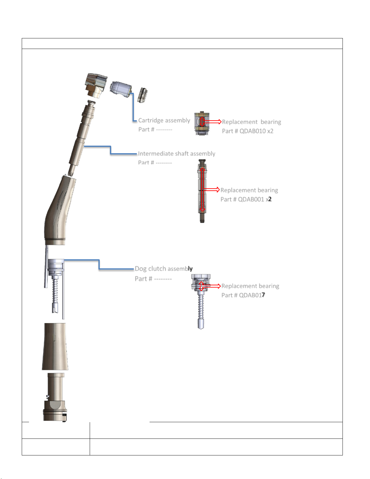
Cartridge assembly
Intermediate shaft assembly
Dog clutch
Replacement bearing
Part # QDAB010 x2
Replacement bearing
Replacement bearing
Replacement part diagram
Part # --------
Part # QDAB001 x2
assembly
Part # --------
Part # QDAB017
Page 2
2-Base nut tool part
# E015
3-Base disassembly
tool # E016
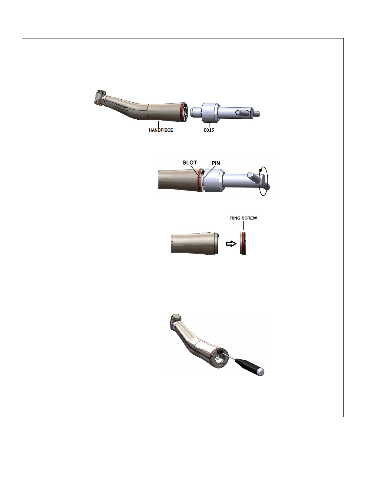
1-To remove the ring screw on the back of the handpiece
+ Align and engage the pins on tool E015 and slots on ring screw on the back end of the
handpiece. Fig. 1
4-water guide removal
tool # E014
5- Additional tools:
+Small flat head screw
driver (
1.5mm diameter)
+Pliers with emery
cloth to prevent
Fig. 1
+ Turn counter-clockwise to open and remove the ring screw. Fig. 2 & Fig. 3
scratch on body of
handpiece.
Fig. 2
Fig. 3
INSTRUCTION:
2- To remove base block from back end of the handpiece
+ Loosen the drive shaft retaining screw with small screw driver(1.5mm) Fig. 4
Fig. 4
+ Before using base disassembly tool part # E016; Adjust the plastic push rod by turning
the wing nut to make sure the plastic rod end is flushed with the front end of the tool. Fig.
5
Page 3

+ Gently pull to remove the base insert form handpiece shell. Fig. 9
Fig. 5
+ Insert the tool into the back end of handpiece, rotate clockwise until the handpiece index
pin locks into slot on the tool. Fig. 6
Fig. 6
+ Turn the wing nut clockwise until the base insert starts to pull out from the handpiece
shell, approximately 5 mm. Fig. 7
+ Press the button on the side of tool E016 tool to remove from the base insert. Fig. 8
Fig. 7
Fig. 8
Page 4

head assembly. Fig. 13
Fig. 9
INSTRUCTION:
3- To remove the Dog Clutch
+ Use emery cloth wound around the grip sleeve and the elbow and turn counterclockwise to detach the grip sleeve. Fig. 10
Fig. 10
+ Hold and pull the drive shaft retaining pin to remove the dog clutch from the shell. Fig.
11
Fig. 11
INSTRUCTION:
4-To remove intermediate Shaft
+ Detach the head assembly from the elbow assembly by holding on the elbow and pull the
head to remove. Fig. 12
Fig. 12
+ Use 7.00mm wrench turn counter-clocwise to remove the intermediate Shaft out of the
Page 5

+ Check and replace o-rings for air/water lines on head assembly. Fig. 17
Fig. 13
INSTRUCTION:
5-To remove the cartridge.
+ Use cap wrench # E013; turn counter-clockwise to open and remove the head cap. Fig.
14
Fig. 14
+ Use blank bur to press to remove the cartrigde out of the head shell. Fig. 15
Fig. 15
INSTRUCTION:
6-To repair water leakage.
+ Use water guide removal tool E014 to remove the air/water tube guides and replace orings. Fig. 16
Fig. 16
Page 6

Fig. 20
Fig. 17
INSTRUCTION:
7- Reassembly cautions:
+ Reverse the procedure for disassembly with following cautions.
+ Make sure slot and pin on head shell and cartridge assembly are aligned before insert the
cartridge into the head shell. Fig. 18
Fig. 18
+ Align o-ring on head assembly and tips of air/water lines, press the head assembly down
to the elbow assembly until click is heard. Fig. 19
Fig. 19
+ Apply silicon adhesive to the fiber optic hole of the base insert prior to press it into the
back end of the handpiece. Fig. 20
QUALITY DENTAL SERVICES CORP.
1681 BEACON PL., OXNARD, CA 93033
(805) 483-5700 TOLL FREE: (800)543-4408
FAX: (805) 784-7804
www.qualitydentalservices.com
 Loading...