

Page 1
Page 2

English
Contents
1. Introduction ..................................................2
1-1 Outline .......................................................................2
1-2 User and Indication for Use .........................................2
1-3 Precautions for handling and operation ........................3
1-4 Classification of Equipment .........................................6
2. Components .................................................7
2-1 List of components .....................................................7
2-2 Part Names of Control Unit and Main Unit ....................8
3. Preparations for Use ...................................12
3-1 Installing the Main Unit and the Control Unit ...............12
3-2 Connecting the Tubing ..............................................13
3-3 Connecting the Motor Cord .......................................14
3-4 Connecting the AC Adapter .......................................14
3-5 Connecting the AC Power Cord ..................................15
3-6 Connecting / disconnecting the motor ........................15
and motor cord
3-7 Connecting / disconnecting the motor ........................16
and the handpiece (option)
3-8 Changing the settings for various functions ................17
3-9 Check before treatment ............................................21
4. Operation Procedure ...................................22
4-1 General Application Mode .........................................23
4-2 Rotary Endo Mode (NLZ E only) .................................24
4-3 Reciprocating Endo Mode (NLZ E only) .......................27
4-4 Contra-Check Function .............................................28
4-5 Sound Volume ..........................................................33
(When the load exceeds the set torque limit value,
Error etc.)
4-6 Last Memory Function ..............................................34
4-7 Initializing Program ................................................... 34
(Restoring the Factory Setting)
4-8 Overheat Prevention .................................................36
English
5. Post-use Maintenance ................................38
5-1 Cleaning at point-of use (Motor) ................................38
5-2 Cleaning, Disinfecting (Motor) .................................... 40
5-3 Packaging, Sterilizing, ...............................................41
Drying and Storage (Motor)
5-4 Cleaning, Disinfecting ............................................... 42
(Control unit, motor cord)
6. Maintenance ............................................... 43
6-1 Replacing the O-rings (Motor insert) ..........................43
6-2 Replacing the O-rings (Motor rear side) ......................44
6-3 Periodical Maintenance Checks .................................45
7. Troubleshooting ..........................................46
7-1 Error Code ...............................................................46
7-2 Troubles and Actions ................................................. 47
8. Specifications .............................................48
8-1 Specifications ...........................................................48
8-2 Symbol ....................................................................49
9. After-sales Service ......................................50
9-1 Warranty ..................................................................50
9-2 Spare Parts List ........................................................50
9-3 Option Parts List .......................................................51
9-4 Disposing product .....................................................51
10. EMC Information .........................................52
(Electromagnetic Compatibility Information)
1
Page 3
Introduction
1
CAUTION
U.S. Federal law restricts this device to be used by or on the order of a licensed dental professional.
Thank you for purchasing the NSK NLZ E / NLZ motor system.
This product can be connected to a dental unit (air unit), which is currently in use, to equip it with a
brushless electric micromotor with LED light.
Please read this Operation Manual carefully before use for operation instructions and maintenance
guidelines to increase overall product life span. Keep this Operation Manual in a handy place for future
reference.
Outline
1-1
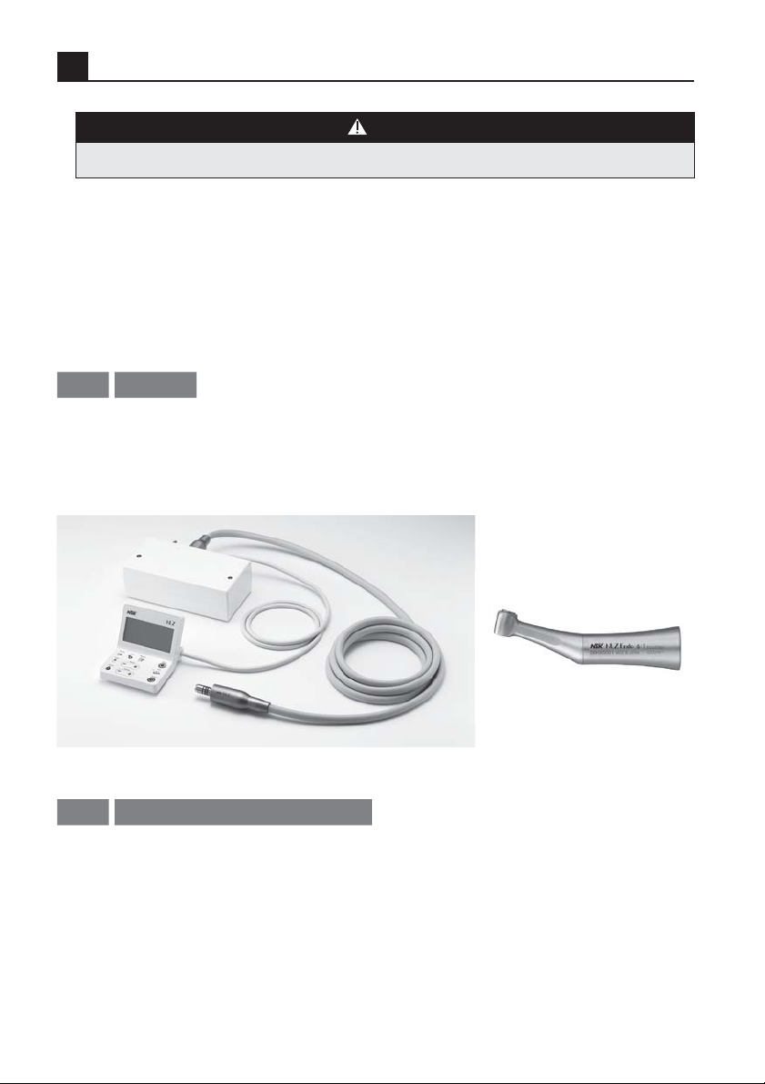
NLZ Motor Systems are available in two models.
NLZ Motor Set, which consists of the main unit, the control unit (Endo function not available) and the
Motor.
NLZ E Motor Set, which consists of the main unit, the control unit (Endo function available) and the Motor.
Optional
User and Indications for Use
1-2
User:
U.S. Federal law restricts this device to be used by or on the order of a licensed dental professional.
Indications for Use:
The NLZ Motor System is intended for use by dental professionals in the performance of dental restoration,
prophylaxis and endodontic procedures.
The NLZ Endo is intended for use by dental professionals in the performance of dental endodontic
procedures.
2
Page 4
Introduction
1-3
Precautions for handling and operation
ŘPlease read these precautions carefully and use only as intended or instructed.
ŘSafety instructions are intended to avoid potential hazards that could result in personal injury or damage
to the device. Safety instructions are classified as follows in accordance with the seriousness of the risk.
Class Degree of Risk
WARNING
CAUTION
NOTICE
ŘDo not disassemble, adjust or alter the motor or handpiece except as recommended by NSK in this Operation
Manual.
ŘDo not handle the AC power cord or any other components of this system with wet hands. Touching electrical
devices with wet hands may result in electric shock.
ŘAvoid splashing water into or near the control unit. Otherwise it could cause short circuits and lead to fire and/or
electric shock.
ŘDo not allow any impact on to the product. Do not drop the product. Doing so might cause electric shock or
malfunction.
ŘDo not operate this product close to patients with cardiac pacemakers. It may affect the function of pacemaker.
ŘKeep this product away from explosive substances and flammable materials. Also, do not use this product on or
near patients who have been administered flammable anesthesia, such as dinitrogen monoxide.
ŘIf the product overheats or smells like burning, immediately turn OFF the power switch, disconnect the power
plug (by pulling the plug, not the cable) and contact your Authorized NSK Dealer.
ŘWhen using of this equipment adjacent to or stacked with other equipment, this equipment and the other
equipment should be observed to verify that they are operating normally.
ŘConnect the handpiece to the motor, rotate before using to check for motor/handpiece vibration, noise or
overheating. If any abnormalities occur, stop using the product immediately and contact your Authorized NSK
Dealer. (Refer to "3-9 Check before treatment")
ŘShould the product function abnormally during use, stop using the product immediately and contact your
Authorized NSK Dealer.
ŘIf the product has not been used for a long period, rotate the motor/handpiece and check for noise, vibration or
overheating before use.
<Motor, Handpiece (Option)>
ŘImmediately after a treatment (within 1 hour), perform maintenance and then store the motor and the handpiece.
Failure to properly maintain the motor and the handpiece may lead to overheating, causing infection, burn
injuries or product failure. Follow maintenance procedures as instructed in this manual and operation manual of
the handpiece.
Hazard that could result in serious injury or damage to the device if the
safety instructions are not correctly followed.
Hazard that could result in light or moderate injury or damage to the device
if the safety instructions are not correctly followed.
General product specification information highlighted to avoid product
malfunction and performance reduction.
WARNING
English
3
Page 5

Introduction
CAUTION
ŘPlace the most priority on patient safety.
ŘThe product is designed only for clinical dental use by qualified personnel. This product must not be used for oral
surgery, implants or dental laboratory work.
ŘThis product may be used only by Dental Professionals, such as Dentists in dental clinics or other medical
premises including hospitals.
ŘThe product must be used in a dental clinic, hospital or other dental institution.
ŘThe user shall be responsible for any judgment that relates to the application of this product to a patient.
ŘThe user is responsible for the operational control, maintenance and continual inspection of this product.
ŘDo not use the product outside the specified use environment. It may cause malfunction. (Refer to “8-1
Specifications”)
ŘOperators and all others in the area must wear eye protection and a mask when operating this handpiece.
ŘUse only the AC adapter, AC power cord provided with the product. Never use other AC adapters. Doing so might
cause a malfunction.
ŘThe AC power cord is the means to cut off commercial power supply. Make sure that the AC power cord can be
pulled out from the power outlet without delay in an emergency. Do not place any articles within 15cm of the AC
power cord.
ŘWhen dirt adheres to the control unit, main unit or AC Adaptor, turn OFF the power, wipe off the dirt with a firmly
wrung moist cloth, and then wipe thoroughly with a soft, dry cloth.
ŘDo not use the following fluids to wipe, immerse or clean the product; strong / super acid water, strong acid /
alkaline chemicals, chlorine-containing solutions, solvents such as benzene or thinner. (Refer to “5. Post-use
Maintenance”)
ŘPerform regular function and maintenance checks. (Refer to “6-3 Periodical Maintenance Checks”)
ŘThis product is rated Medical Electrical equipment. EMC (Electromagnetic compatibility) is described in the
documentation included. Installation and use of this product requires special precautions regarding EMC
according to the EMC information. (Refer to “10. EMC Information (Electromagnetic Compatibility Information”))
ŘPortable and mobile RF communications equipment can affect Medical Electrical equipment. Do not use RF
equipment near the product.
ŘUse only authorized components. Use of other components might impair the EMC performance of the product.
ŘMake sure that each part is properly connected. Improper connections might cause faulty operation, LED lighting
failure and water or air leakage.
ŘThe AC power cord included with the product has the length of 2 meters. Bundle and fix the extra cord to prevent
the operator or the patient from inadvertently stepping on it.
<Control Unit, Main Unit>
ŘWhen disconnecting the AC power cord, motor cord or other cords, hold the cords by their plug and pull the plug
out. Holding and pulling the cord might snap the wiring in the cord and cause a malfunction.
ŘWhen installing the control unit, motor and other components, provide enough room to avoid bending or twisting
the tubing or the cord.
ŘDo not sterilize the control unit, main unit, AC adapter, AC power cord, motor cord.
4
Page 6

Introduction
<Motor, Handpiece (Option)>
ŘThe output torque changes according to the type of handpiece connected to the motor, operating conditions
and other factors. Be sure to use a handpiece made by NSK. (Refer to “4-4 Contra-Check Function”) Use of a
handpiece made by a different manufacturer might cause trouble such as disparity between the preset and the
output torque.
ŘEnsure that the motor has completely stopped rotating before handling. Connecting or disconnecting the
handpiece while the motor is rotating may result in injuries or damage the handpiece.
ŘDo not point the light illuminated from the motor and handpiece directly into patient's or operator's eyes. Doing
so might damage the eyes.
ŘThe motor is delivered in a non-sterile condition and must be performed steam sterilization prior to use.
ŘDo not lubricate the motor. It may cause overheating and product failure.
ŘUse moisture- and dust-free air as the supply air. Mixing in of moisture might cause malfunction or heat
generation.
ŘConnect only ISO 9168-compliant, Type 2 (Midwest 4 holes), or Type 3 (ISO-compliant standard 4 holes with
light) tubing.
ŘMake sure to supply coolant air. Otherwise, the motor/handpiece surface might reach a temperature of 51°C or
higher.
NOTICE
Ř
During operation, the motor and motor cord may affect computers, LAN cables in the vicinity of use.
Noise could be heard during operation near a radio receiver.
Ř
Use the "Power Key" to turn ON/OFF the power on a daily basis. If the system is not used for a long
period of time or if the system malfunctions, turn OFF the power of the main unit, disconnect the
power cord, and drain water from main unit, tubing and motor cord.
Ř
For details on handling the handpiece, refer to the Operation Manual of the handpiece.
Ř
Only authorized service personnel should inspect inside the product by following the instructions in
the service manual. Leave the product with your Authorized NSK Dealer, if necessary.
Ř
No special training is required to operate this device.
Ř
Drain water from the main unit, turbing and motor cord, if the main unit is not to be used for a long
time.
English
5
Page 7

Introduction
Classification of Equipment
1-4
ŘType of protection against electric shock:
- Class ll equipment
ŘDegree of protection against electric shock:
- Type B applied part:
ŘMethod of sterilization or disinfection recommended by the manufacturer:
- Refer to ”5-3 Packaging, Sterilizing, Drying and Storage (Motor)”
ŘDegree of protection against ingress of water as detailed in the current edition of IEC 60529:
- Control Unit: IPX0 (Not protected)
ŘDegree of safety of application in the presence of a flammable anesthetic mixture with air or with oxygen
or nitrous oxide:
- Equipment NOT suitable for use in the presence of a flammable anesthetic mixture with air or with oxygen
or nitrous oxide.
ŘMode of operation:
- Intermittent operation ( ON:3 min, OFF:10min.)
(Applied parts: Motor, Handpiece)
6
Page 8
Components
2
2-1
List of components
1
5
9
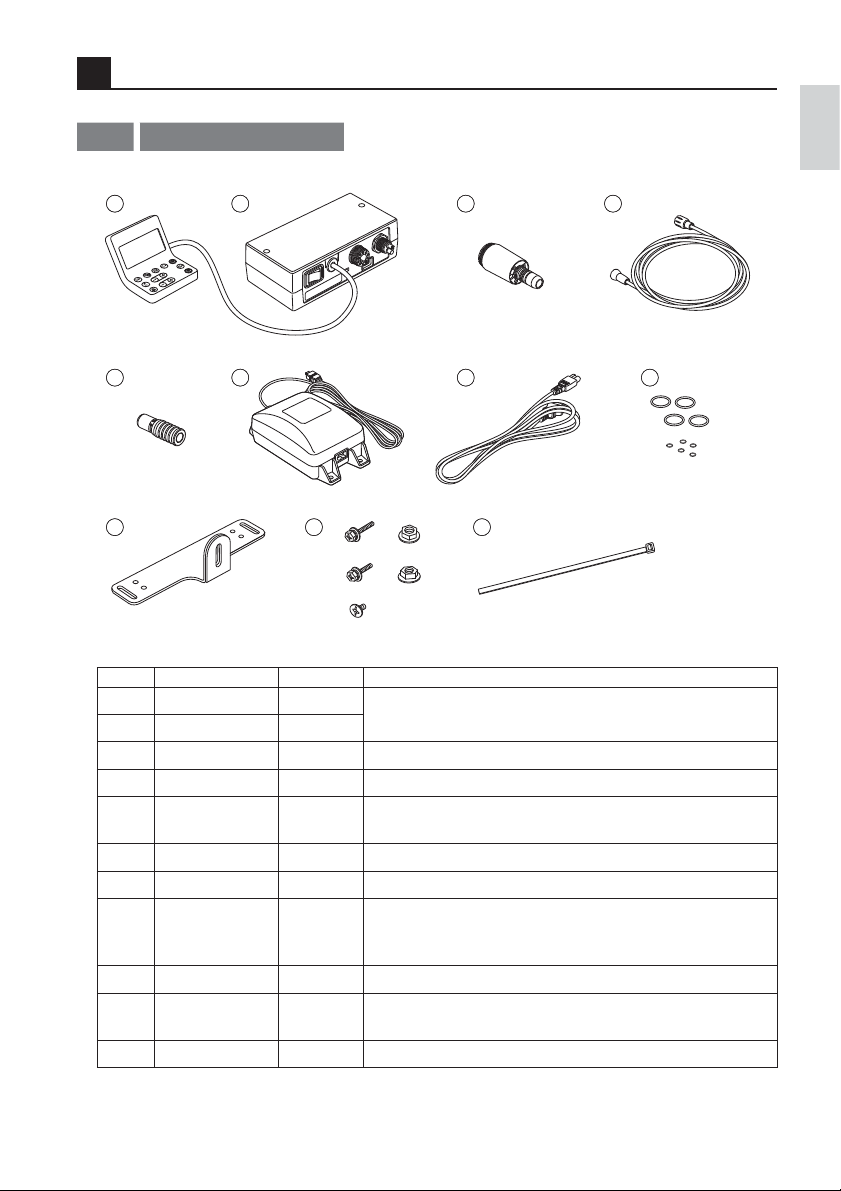
No. Part Name Quantity Remark
1 Control unit 1
2 Main unit 1
3 Motor 1 4 Motor cord 1 Cord length: 1.8m
5 Purge nozzle 1
6 AC adapter 1 Cord length: 5m
7 AC power cord 1 Cord length: 2m
8 O-ring set 1set
9 Mounting bracket 1 For the main unit
Mounting screws
10
and nuts
11 Cable tie 2 For fixing the link cable
2
6
10 11
The control unit and the main unit are connected via the link cable.
For purging excess oil (compatible with ISO 3964-compliant
handpieces)
Spare parts
For the motor insert joint (Black: 3pcs., Blue: 1 pc.)
For the pipes at the rear side of the motor (Black: 5 small pcs.)
1set
M5x30 screw (2 pcs.), M4x30 screw (2 pcs.), M4 flat head screw (2
pcs.), M5 nut (2 pcs.), M4 nut (2 pcs.)
3
7
English
4
8
7
Page 9

Components
Part Names of Control Unit and Main Unit
2-2
Link cable
(cable length: 1m)
LCD Display
Control panel AC power cord connector
< Control Unit > < Main Unit >
Power switch
Motor cord connector
Tubing connector
8
Page 10
Components
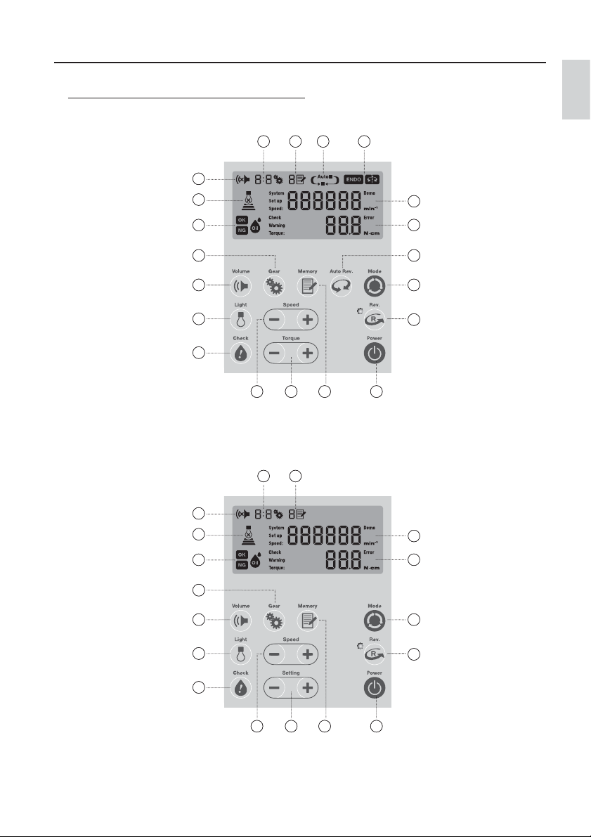
LCD Display and the Control Panel of the Control Unit
< NLZ E >
F3G2H
E
D
C
8
7
6
5
4
< NLZ >
F3G
English
I
A
B
9
10
11
1
E
D
C
8
7
6
5
4
2
A
B
10
11
1
9
Page 11
Components
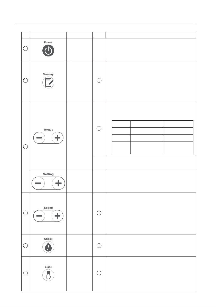
No. Key Name Display Function
1
2
3
Power Key -
Memory Key
Torque Key
(NLZ E)
Setting Key
(NLZ)
Press once to turn ON the power. When the power is ON,
hold it down for more than two seconds to turn OFF the
power
In General Application Mode:
Motor speed can be adjusted between 100 and
40,000 min-1.
G
In Rotary Endo Mode:
Motor speed can be adjusted between 100 and
6,000 min-1.
*Display value changes interlocked with the gear ratio.
When gear ratio is set by each time pressing this key you
can adjust the torque.
Rotary Endo Mode
B
Gear Ratio Torque Range (N·cm) Increment (N·cm)
1:1 0.3 - 3.0 0.1
4:1 0.8 - 6.0 0.4
6:1 1.0 - 6.0 1.0 - 1.2:0.2
Change the setting as described in “3-8 Changing the
settings for various functions”
Change the setting as described in “3-8 Changing the
settings for various functions”
1.2 - 6.0:0.6
In General Application Mode:
Motor speed can be adjusted between 100 and
40,000 min-1.
4
5
6
Speed Key
Check Key
Light Key
A
In Rotary Endo Mode:
Motor speed can be adjusted between 100 and
6,000 min-1.
*Display value changes interlocked with the gear ratio.
Check the status of the handpiece as described in “4-4
C
Contra-Check Function”
Set light intensity (Strong·Moderate·Weak·OFF)
By each time pressing this key you can change the
volume from OFF -> intensity 1 -> intensity 2 -> intensity
D
3 and then back to OFF again
* The light can be turned on for 5 seconds by pressing the
key while the motor is stopped.
10
Page 12
Components
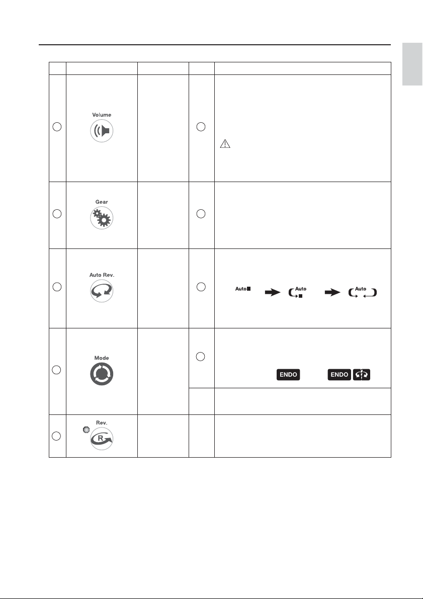
No. Key Name Display Function
Set the volume of the notifying sound generated when
reaching a set torque limit value or when errors occur
(High·Low·OFF)
By each time pressing this key you can change the
7
Volume Key
volume from OFF -> volume 1 -> volume 2 and then
E
back to OFF again
CAUTION
When the volume is set to OFF, there will be no alarm
sound. Care should be taken when using the system with
the volume set to OFF.
By each time pressing this key you can switch the gear
ratio
8
Gear Key
from 1:5 -> 1:1 -> 4:1 -> 6:1 -> and then back to 1:5
F
again – in General Application Mode
from 1:1 -> 4:1 -> 6:1 -> and then back to 1:1 again –
in Rotary Endo Mode
By each time pressing this key you can switch the mode
Auto Rev. Key
9
(NLZ E)
*Rotary Endo
Mode Only
between AUTO STOP -> AUTO REVERSE STOP -> AUTO
REVERSE FORWARD and then back to AUTO STOP again
H
AUTO STOP
AUTO REVERSE
STOP
Toggles between 3 application modes as below
Mode Key
(NLZ E)
10
Setting Mode
I
General
Application Mode:
No display
Rotary Endo
Mode:
Key
(NLZ)
Change the setting as described in “3-8 Changing the
settings for various functions”
English
AUTO REVERSE
FORWARD
Reciprocating Endo Mode:
11
Rev. Key -
The rotation direction can be changed by this key. The
LED lights up during reverse rotation.
11
Page 13
Preparations for Use
3
CAUTION
Make sure that each part is properly connected. Improper connections might cause faulty operation, LED lighting
failure and water or air leakage.
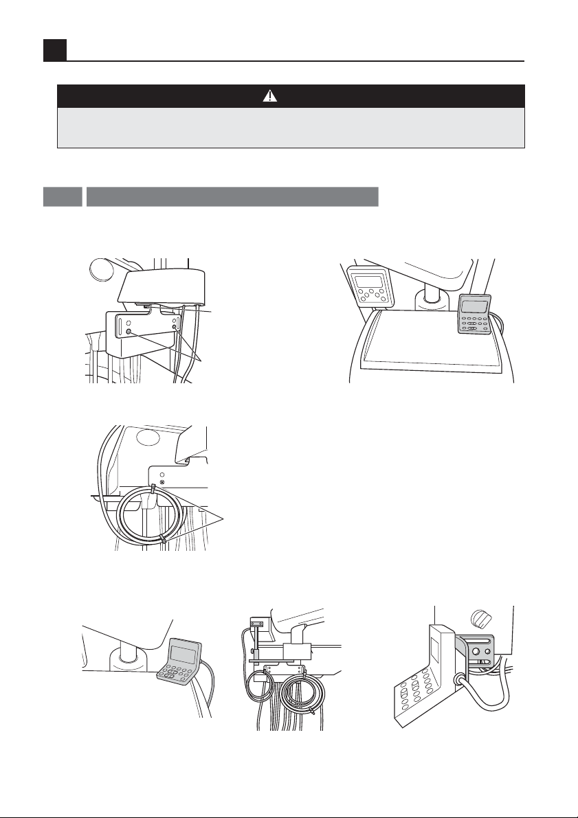
Installing the Main Unit and the Control Unit
3-1
Fix the main unit to the dental unit using the
1
screws. As shown below:
M4x30, M5x30
with the nut
( included)
M4 flat head screw
( included )
Bundle the link cable appropriately and fix it by cable tie.
3
Cable tie
(included)
If you wish to install as shown below, optional parts are available for purchase.
4
( Refer to “ 9-3 Optional Parts List ” )
2
Place the control unit on the tray of the dental
unit.
Installation example using
NLZ STAY
Installation example using
NLZ MOUNTING PLATE
12
Page 14

Preparations for Use
CAUTION
ŘKeep the main unit away from water.
ŘThe control unit incorporates a LCD panel. Place the unit where the operator can see the display.
ŘDo not bend the tubing forcibly when putting the main unit in place. Allow some extra space for tubing to avoid
pinching or bending it.
3-2
Connecting the Tubing
Align the tubing from the dental unit and the tubing connector at the
back of the main unit (1). Insert it firmly and tighten it completely
(2).
①
IN
OUT
AC28V
POWER
CAUTION
ŘBe sure that there is no air or water coming from tubing when attaching it to the main unit.
ŘUse moisture- and dust-free air as the supply air. Mixing in of moisture might cause malfunction or heat
generation.
ŘScrew the nut properly without unnatural force, when you plug in tubing connector and motor cord connector.
Avoid cross threading.
ŘConnect only ISO 9168-compliant, Type 2 (Midwest 4 holes), or Type 3 (ISO-compliant standard 4 holes with
light) tubing.
ŘAir requirement: dry, free from contamination and oil. Use a compressor with a dry air system. Install an air filter
if necessary. Blow out the lines before installation.
ŘDo not pull the tubing using more than necessary force.
ŘMake sure to supply coolant air. Otherwise, the motor/handpiece surface might reach a temperature of 51°C or
higher.
English
②
13
Page 15

Preparations for Use
C
Connecting the Motor Cord
3-3
Align the motor cord plug and the motor connector at the back of the
main unit (
1
). Insert it firmly and tighten it completely (2).
CAUTION
ŘGently screw in the nut of the motor cord plug when tightening it.
ŘDo not pull the motor cord using more than necessary force.
Connecting the AC Adapter
3-4
Check that main power switch is off. ( side)
1
OUT
A
POWER
IN
OUT
AC28V
POWER
Insert the AC adapter plug, with the arrow facing
2
up, into the AC power cord connector at the back
①
of the main unit firmly.
IN
OUT
AC28V
POWER
②
14
Page 16
Preparations for Use
3-5
Connecting the AC Power Cord
Insert the AC power cord into the inlet of the AC
1
adapter.
Insert the AC power cord plug to commercial
2
power supply outlet.
CAUTION
ŘDuring this procedure the power switch of the main unit should remain OFF.
ŘThe AC power cord included with the product has the length of 2 meters. Bundle and fix the extra cord to prevent
the operator or the patient from inadvertently stepping on it.
ŘUse only the AC adapter, AC power cord provided with the product. Never use other AC adapters. Doing so might
cause a malfunction.
ŘWhen disconnecting the AC power cord, motor cord or other cords, hold the cords by their plug and pull the plug
out. Holding and pulling the cord might snap the wiring in the cord and cause a malfunction.
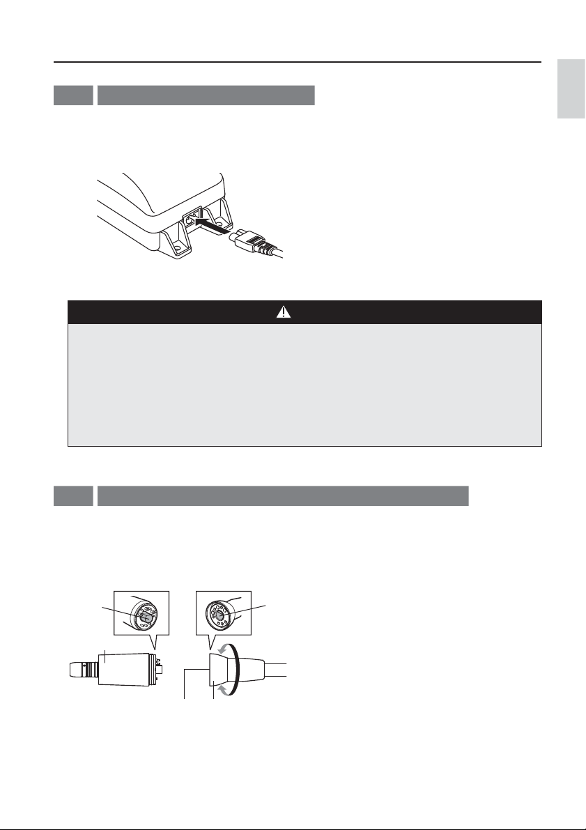
3-6
Connecting / disconnecting the motor and motor Cord
English
<Connecting> <Disconnecting>
Align and insert the pins of the connector carefully and
firmly into the pin holes of the motor, and fasten the
motor nut securely.
Pin
Motor
Motor Cord NutMotor Cord Connector
Hole
Tighten
Loosen
Unscrew and detach the motor cord nut, and gently
pull out the motor cord.
15
Page 17
Preparations for Use
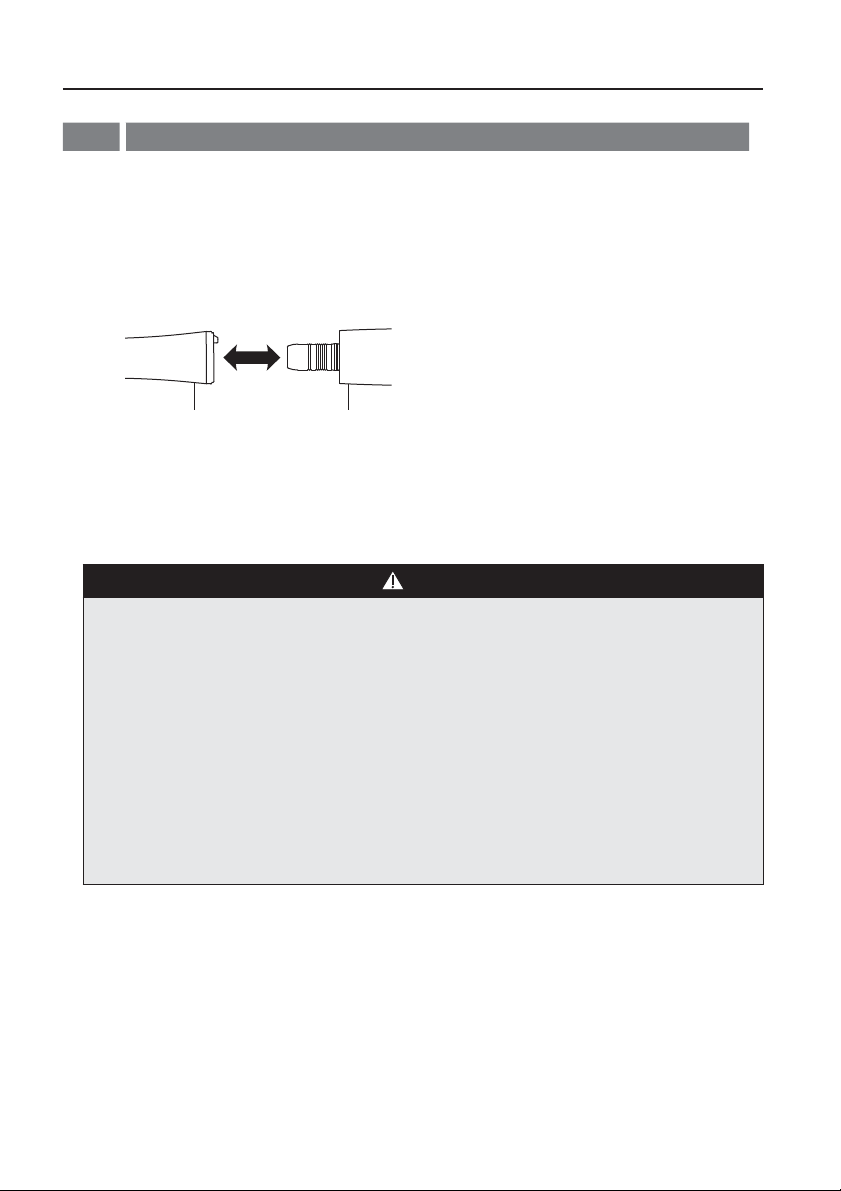
Connecting / disconnecting the motor and the handpiece (option)
3-7
<Connecting>
Insert the E-type handpiece into the motor insert,
1
and turn until it clicks as the positioning pin on
the handpiece falls into positioning hole on the
motor.
<Disconnecting>
Simply pull out the handpiece from the motor.
MotorHandpiece (option)
Confirm that the handpiece is securely connected
2
to the motor.
CAUTION
ŘEnsure that the motor has completely stopped rotating before handling. Connecting or disconnecting the
handpiece while the motor is rotating may result in injuries or damage the handpiece.
ŘBe sure to adjust the rotation speed of the motor within the allowable rotation speed of the handpiece (option).
ŘLubricated handpiece should stand and allow oil to drain prior to steam sterilization cycle. Attach to the motor
after the excess oil has been completely drained. If the oil enters the motor, it may cause malfunction of the
motor.
ŘAfter lubrication, keep the handpiece standing apart from the motor. Connect the handpiece to the motor when
using.
ŘDo not allow water to enter the motor. It may cause malfunction of the motor.
ŘBefore each use, operate the motor outside the patient's oral cavity. If any abnormality, such as vibration, noise
or overheating occurs, stop using the product immediately and contact your Authorized NSK Dealer. (Refer to
"3-9 Check before treatment")
16
Page 18
Preparations for Use
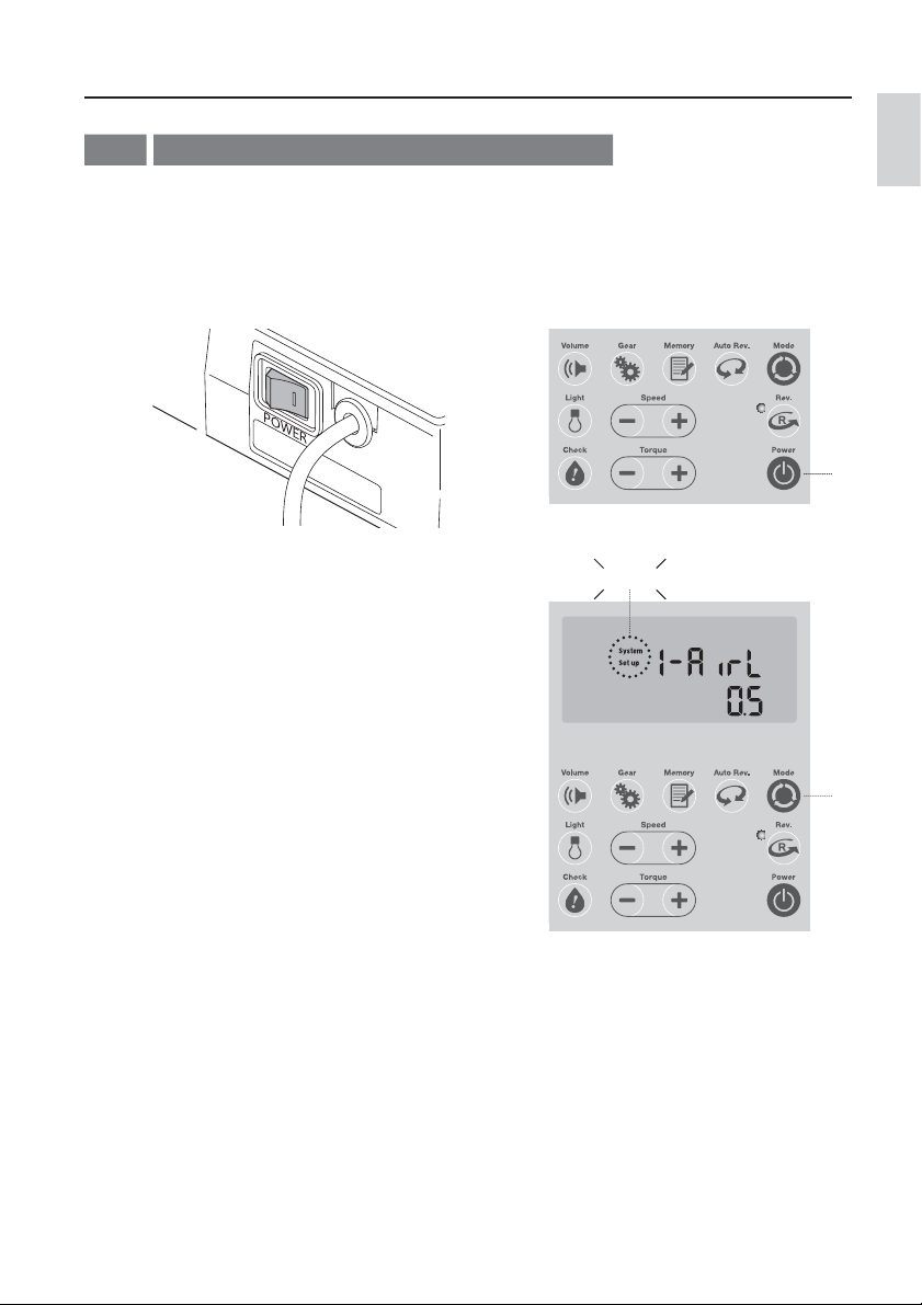
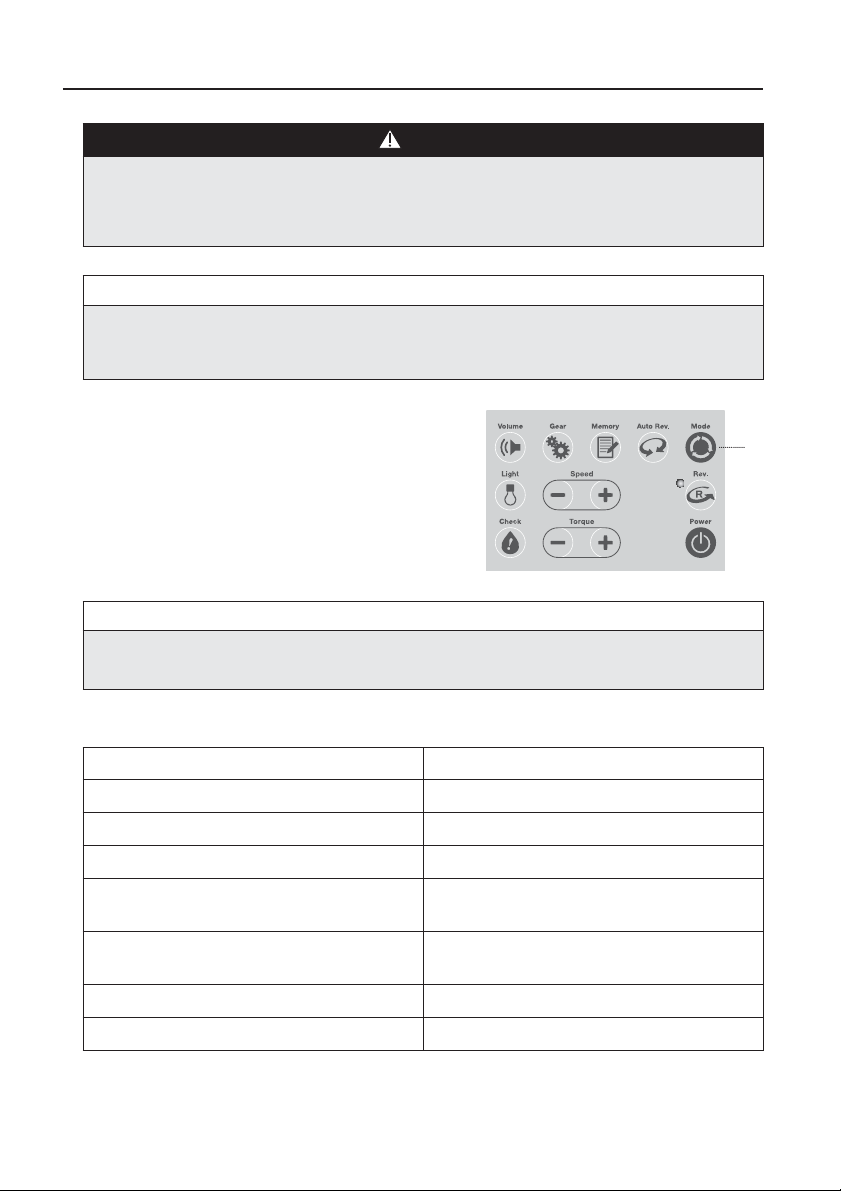
3-8
Changing the settings for various functions
Settings for various functions can be changed from their default values. This is to make the system easier
to use, when it is used for the first time after purchase. You will need to enter into the setup mode, change
the settings and save the new ones as below:
Turn ON ( I side ) the power switch on the main
1
unit.
Hold down the Mode Key* for more than two
3
seconds. With an alarm sound, "System" and
"Setup" on the LCD display will start blinking and
the system will enter into the setup mode.
* The Setting Mode Key in case of NLZ
Press the Power Key on the control unit.
2
Blinking
English
2
17
3
Page 19
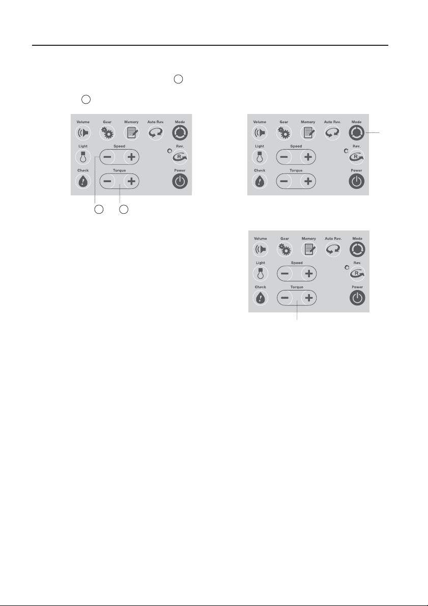
Preparations for Use
In the setup mode, the function item can be
4
selected using the Speed Key (+/-) (
the value can be changed using the Torque Key
(+/-)* (2).
* The Setting Key (+/-) in case of NLZ
1
2
4-
4-
Change the settings by pressing the Torque Key
6
(+/-). * The Setting Key (+/-) in case of NLZ
1
), and
Once a value is changed, the new value will
5
blink. Press the Mode Key quickly to save the
new value. Once saved, this new value will stop
blinking.
6
5
18
Page 20
Preparations for Use
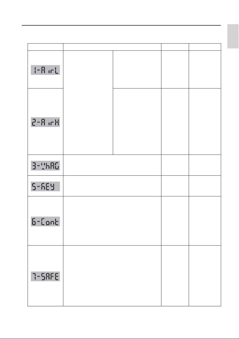
<Setting each function item>
Display Function item Factory Setting Setting Range
Air pressure for motor
startup speed:
This is the lower limit
Foot Air Calibration:
This function enables
you to use the maximum
speed 40,000 min-1, even
though the air pressure
of the dental unit is not
high enough, by setting
air pressures for “motor
startup speed” and
“maximum motor speed”.
Delay time for the light:
This function sets the delay time for the white illumination
lamp going off after the motor stops.
The notifying sound :
This function sets the volume for the operation tone
when a key is pressed.
Contra-Restriction:
This function automatically slows down and stops the
rotation of the motor when the checking result through
Contra-Check is either “OIL” or “NG”. The motor cannot
be activated when the checking result is “NG” blinking
which shows the status of handpiece defect. (Refer
to “4-4 Contra-Check Function” and “4-8 Overheat
Prevention”)
Contra-SAFE:
This is a function to stop the rotation of the motor when
continuous motor high-load current is detected with a 1:5
increasing handpiece.*
In this mode, there are selectable three sensitivity levels:
Fast, standard and Slow and the “Fast” setting offers
the most sensitive response. (Refer to “4-8 Overheat
Prevention”)
*Use NSK handpieces : the model of Z95L, Z85L, X95EX,
X95L, X95, M95L, M95, X85L, X85 of 1:5 Gear Ratio.
of the air pressure at
which the motor starts to
operate.
Air pressure for maximum
motor speed:
This is the upper limit of
the air pressure at which
the motor will run at its
maximum speed.
This value can be set
only when there is an
air supply at a pressure
of equal or higher than
1.5bar.
0.5bar
(0.05MPa)
1.8bar
(0.18MPa)
3 seconds
High=2
ON=1
Standard=2
English
0.3 – 3.0bar
(0.03 - 0.3MPa)
(@ 0.1bar
increments)
1.5 - 3.0bar
(0.15 - 0.3MPa)
(@ 0.1bar
increments)
0 - 10 seconds
(@ 1sec.
increments)
High=2
Low=1
OFF=0
ON=1
OFF=0
Fast=3
Standard=2
Slow=1
No stop=0
19
Page 21
Preparations for Use
WARNING
NSK recommends to always activate both functions of " Contra-Restriction" and "Contra-SAFE" because using
these functions under “Off” or “No stop” may increase the probability or severity of overheating of defective or
poorly maintained handpieces.
NOTICE
Set the lower air pressure limit at motor start-up, lower than the upper air pressure limit at maximum
rotation of the motor.
After you are finished making changes, hold down the
7
Mode Key again for more than two seconds to return to
the regular screen.
NOTICE
Notifying sound will not be generated when the sound volume is set to OFF. Be aware of this while using the
system when the sound volume setting is OFF.
7
<Notifying sound during key operation>
Items Notifying sound
When turning on the power 1 short beep
When turning off the power 1 short beep followed by 1 long beep
When pressing the keys 1 short beep
When pressing and holding the Speed Key/Torque Key
When reaching upper/ lower setting limit, when
becoming inoperable
When switching to the function setting mode 1 long beep
When storing into the memory 2 short beeps
1 short beep followed by successive short beeps while
the key is being pressed.
3 short beeps
20
Page 22

Preparations for Use
3-9
Check before treatment
ŘBefore each use, operate the motor outside the patient's oral cavity.
ŘMake sure the light is working properly and there is enough water spray.
CAUTION
If any abnormality, such as vibration, noise or overheating occurs, stop using the product immediately and contact
your Authorized NSK Dealer.
English
21
Page 23

Operation Procedure
4
Refer to “2-2 Part Names of Control Unit and Main Unit”, which explains the functions of the system in
detail.To start operation, insert the power cord plug into an outlet and turn ON the equipment. The LCD
Display will light. This product has two power control functions. The "Power Key" on the control panel and
the "Power Switch" on the main unit. Use the "Power Key" to turn ON/OFF the power on a daily basis. Use
the "Power Switch" to turn OFF the power when the equipment is not being used for a long period of time
or when the equipment is malfunctioning.
<Mode explanation>
Both NLZ Motor Set and NLZ E Motor Set provide general application mode which is used for dental
restoration and prophylaxis. In this mode, the rotation speed can be adjusted.
The “Rotary Endo Mode” and “Reciprocating Endo Mode” are used for the endodontic procedure, which
are provided only under NLZ E Motor Set.
Rotary endo mode provides low rotation speed for use with gear ratio 1:1, 4:1, and 6:1 handpieces.The
value of rotation speed and torque can be adjusted.
(Refer to “4-2 Rotary Endo Mode (NLZ E Only) <Auto Reverse Function>)
Pressing the “Check” key to perform “Contra-Check” Function before use, the status of a handpiece can
be evaluated as “OK”, “OIL”, “NG” or “NG Blinking”. When the handpiece is evaluated “OK”, the ContraCheck Function works as a torque calibration. (Refer to “4-4 Contra-Check Function)
Under the reciprocating endo mode, automatic unequal bidirectional rotation is provided. The user can not
alter the preset parameters.
<Mode selection>
System General Mode Rotary Endo Mode Reciprocating Endo Mode
NLZ Motor Set
NLZ E Motor Set
ݲ
ݲݲݲ*
Not Available Not Available
*The “Reciprocating Endo Mode” can be operated only with the NLZ Endo Contra Angle handpiece and WaveOne file.
(Refer to “4-3 Reciprocating Endo Mode (NLZ E only)”)
22
Page 24
Operation Procedure
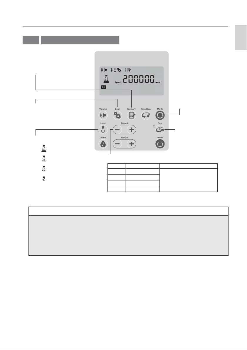
4-1
General Application Mode
Select the program # - 6
2
programs can be selected
Select the gear ratio
3
according to the handpiece
1:5, 1:1, 4:1, 6:1
Set the light intensity
6
Strong
Moderate
Weak
OFF
Select the General
1
Application Mode
(NLZ E only)
Select the rotation
5
direction, FWD / REV
Select the proper speed required for the application
4
Gear Ratio Rotation Speed (min-1) Setting range (min-1)
1:5 500 – 200,000 20 – 100:10 Increment
1:1 100 – 40,000
4:1 30 – 10,000
6:1 20 – 6,600 50,000 – 200,000:5,000 Increment
100 – 1,000:100 Increment
1,000 – 5,000:500 Increment
5,000 – 50,000:1,000 Increment
English
NOTICE
ŘSince the NLZ Endo contra angle handpiece is only for endodontic treatment, it cannot be used for General
Application Mode.
ŘThe rotation speed of the bur, mounted to the handpiece, depends on the gear ratio of the handpiece.
ŘThe actual rotation speed is displayed during operation. The Max set speed is displayed when stopped.
ŘThe max set speed can be adjusted even during rotation by pressing the Speed Keys on the control panel.
Adjust the water spray of the handpiece at the dental unit
7
Contra-Check
8
Perform Contra-Check before treatment. (Refer to “4-4 Contra-Check Function”)
23
Page 25
Operation Procedure
The motor operation will be controlled by the foot pedal of the dental unit (also called Rheostat). Pressing the
9
pedal all the way down will run the motor up to the Max speed set at step 4
Memory setting
10
Press and hold the Memory Key for more than 2 seconds. After 2 short beeps the memory sign will stop blinking
and gear ratio and speed will be memorized in the selected program number (M1 through M6 is shown, so that
up to 6 programs can be stored in memory).
NOTICE
A blinking indicates that the program is not stored in the memory yet.
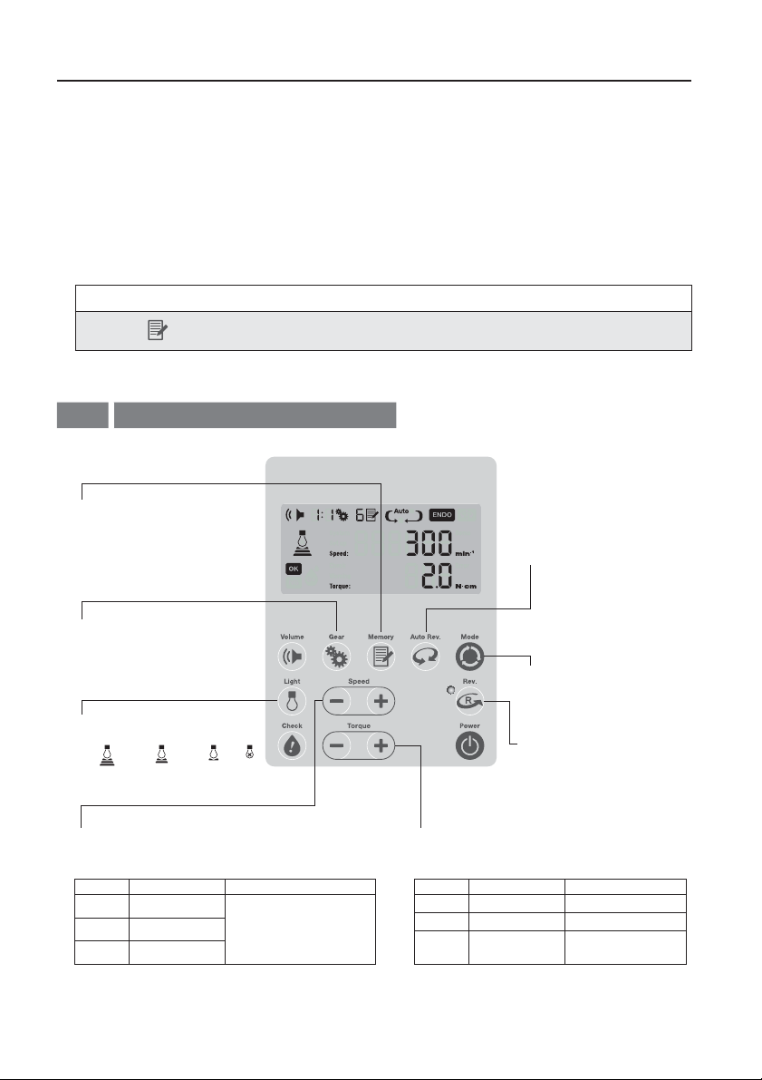
Rotary Endo Mode (NLX E only)
4-2
Select the program # - 6
2
programs can be selected
Select the gear ratio
3
according to the handpiece
1:1, 4:1, 6:1
Set the light intensity
Set the light intensity
8
OFFStrong Moderate Weak
Select the Auto-Reverse
6
Mode: AUTO STOP /
AUTO REVERSE STOP /
AUTO REVERSE
FORWARD
Select the Rotary Endo
1
Mode
Select the rotation
7
direction, FWD / REV
Select the proper speed recommended by
4
file manufacturers
Gear Ratio Rotation Speed (min-1) Setting range (min-1)
1:1 100 – 6,000
4:1 30 – 1,500
6:1 20 – 1,000
20 – 500:10 Increment
500 – 1,000:50 Increment
1,000 – 6,000:100 Increment
24
Select the proper torque recommended
5
by file manufacturers
Torque Setting Range (N・cm)
Gear Ratio
1:1 0.3 – 3.0 0.1 Increment
4:1 0.8 – 6.0 0.4 Increment
6:1 1.0 – 6.0
Setting range (N・cm)
1.0 – 1.2:0.2 Increment
1.2 – 6.0:0.6 Increment
Page 26
Operation Procedure
NOTICE
ŘThe rotation speed of the file, mounted to the handpiece, depends on the gear ratio of the handpiece.
ŘThe actual rotation speed is displayed during operation. The Max set speed is displayed when stopped.
ŘThe max set speed can be adjusted even during rotation by pressing the Speed Keys on the control panel.
Adjust the water spray of the handpiece at the dental unit
9
Turn off the water flow of the dental unit due to lack of water flow circuit inside the NLZ Endo contra angle
handpiece.
Contra-Check
10
Perform Contra-Check before treatment. (Refer to “4-4 Contra-Check Function”)
NOTICE
Depends on the connected contra-angle handpiece, a short beep sound may occur when the rotation
starts, which is not a malfunction.
The motor operation will be controlled by the foot pedal of the dental unit (also called Rheostat). Pressing the
11
pedal all the way down will run the motor up to the Max speed set at step 4
CAUTION
ŘThe torque displayed in the Rotary Endo Mode varies according to the type of the handpiece or using condition.
Make sure to use an NSK-manufactured handpiece and perform the Contra-Check before use. The Contra-Check
will carry out torque calibration. (Refer to “4-4 Contra-Check Function”)
ŘUsing handpieces not manufactured by NSK may cause malfunction including discrepancy between set torque
limit value and the actual output torque.
English
Memory Setting
12
Press and hold the Memory Key for more than 2 seconds. After 2 short beeps the memory sign
stop blinking and gear ratio, rotation speed, torque and auto-reverse mode will be memorized in the selected
program number (M1 through M6 is shown, so that up to 6 programs can be stored in memory).
NOTICE
A blinking
indicates that the program is not stored in the memory yet.
25
will
Page 27
Operation Procedure
<Auto Reverse Function>
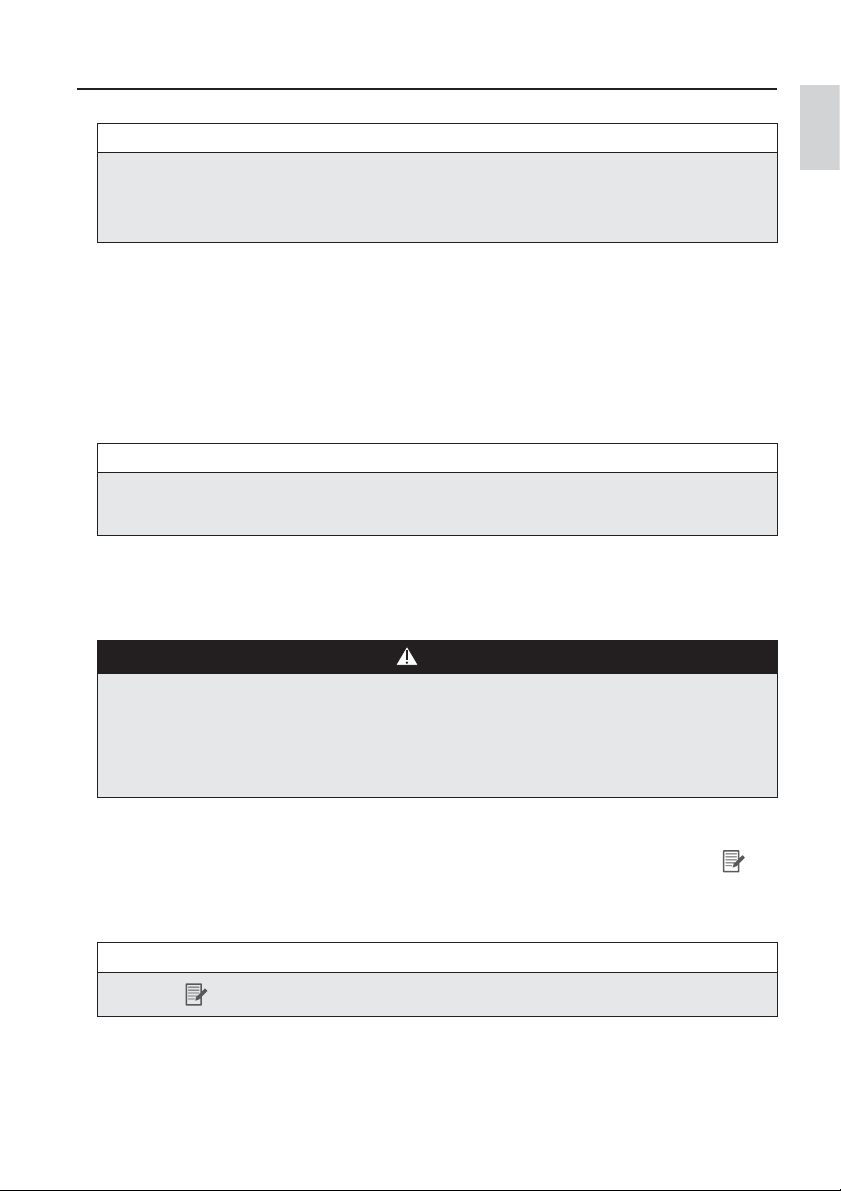
By each time pressing the Auto Rev. Key you can switch the mode between AUTO STOP -> AUTO
REVERSE STOP -> AUTO REVERSE FORWARD and then back to AUTO STOP again
AUTO STOP AUTO REVERSE STOP AUTO REVERSE FORWARD
Explaining the above 3 Modes:
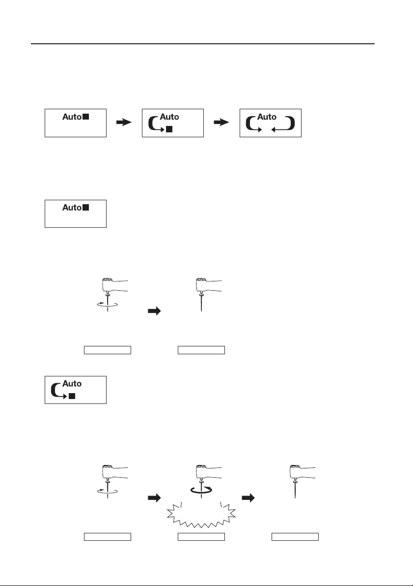
AUTO STOP
The handpiece starts in forward rotation. When a load reaches the set torque limit value, the motor rotation
stops with a beep sound. If the load continues, the set speed on the LCD Display starts blinking until the
foot pedal is released.
Load lower than
the set torque limit value
Forward rotation Stop
When load reaches
the set torque limit value
AUTO REVERSE STOP
The handpiece starts in forward rotation. When a load higher than the torque limit is applied, the file will
rotate in reverse with a beep sound. When the load is removed, the motor rotation stops and the set speed
on the LCD Display starts blinking until the foot pedal is released. If you want the motor to rotate again, repress the foot pedal.
Load lower than
the set torque limit value
Forward rotation Reverse rotation Stop
Load higher than
the set torque limit value
Reverse rotation when load continues,
stop when load is removed
26
Page 28
Operation Procedure
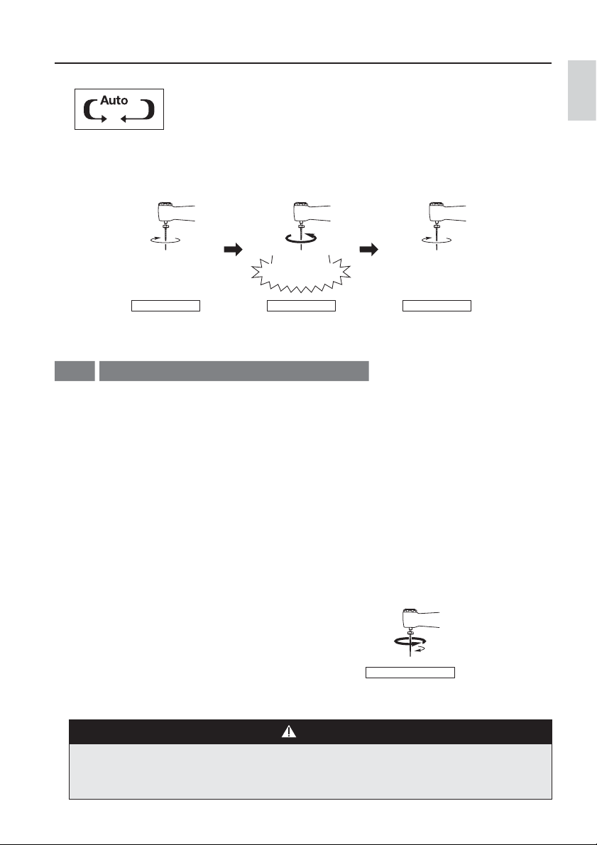
AUTO REVERSE FORWARD
The handpiece starts in forward rotation. When a load higher than the torque limit is applied,
the file will rotate in reverse with a beep sound. When the load is removed, the file will return to normal
rotation (forward) automatically.
Load higher than
the set torque limit value
Reverse rotation when load continues,
return to forward rotation
when load is removed
4-3
Load lower than
the set torque limit value
Forward rotation Return to forwardReverse rotation
Reciprocating Endo Mode (NLZ E only)
The Reciprocating Endo Mode is preset for the NLZ Endo (6:1 reduction Endodontic Contra Angle
Handpiece) using with the WaveOne
®
reciprocating file made by DENTSPLY SIRONA Group. In this mode,
automatic unequal bidirectional rotation is provided and the user can not alter the preset parameters.
Please use the WaveOne
(WaveOne
®
is a registered trademark of DENTSPLY SIRONA Inc.)
Select the Reciprocating Endo Mode.
1
®
Reciprocating file to operate in this mode.
Turn off the water flow of the dental unit due to
2
lack of water flow circuit inside the NLZ Endo
contra angle handpiece.
English
Contra-Check
3
Perform Contra-Check before treatment. (Refer
to “4-4 Contra-Check Function”)
The motor operation will be controlled by the foot
4
pedal of the dental unit (also called Rheostat).
Unequal bidirectional rotation
CAUTION
The Reciprocating Endo Mode has been designed and verified exclusively for the NLZ Endo contra angle handpiece
and WaveOne® reciprocating file manufactured by DENTSPLY SIRONA Group. Using other contra angle handpieces
or files may result in gear’s premature wear, overheating, or file breakage.
27
Page 29

Operation Procedure
Contra-Check Function
4-4
This function evaluates the state of the Contra Angle / Straight Handpiece as:
“OK” : The check result is acceptable
“OIL” : Needs a maintenance such as lubricating with oil
“NG” : There is a serious malfunction
WARNING
ŘDamaged handpiece, Foreign materials in the handpiece, Inadequate Maintenance, and Water Entrance are
risks for overheating/burn event. Those abnormalities appear as vibration, noise or overheating.Check handpiece
for those abnormalities before treatment, or it may cause overheating of handpiece and cause burn in patients.
ŘContra-Check function niether measures the temperature of overheating handpiece directly nor assures to
maintain handpiece safe temperature. As possible risk of overheating still remains even after Contra-Check,
make sure to always check for above abnormalities before treatment.
ŘIf any abnormality, such as vibration, noise or overheating occurs, stop using the handpiece immediately and
contact your authorized NSK dealer.
ŘThis function is only available for NSK Contra Angle /Straight Handpiece : models of Z95L, Z85L, X95EX, X95L,
X95, M95L, M95, X85L, X85 of Gear Ratio 1:5, Z25L, X25L, X25, X65L, X65, M25L, M25, M65 of Gear Ratio
1:1, Z15L, X15L, X15, M15L, M15 of Gear Ratio 4:1 and the NLZ Endo Contra Angle Handpiece of Gear Ratio 6:1.
ŘUse of incorrect handpieces may cause overheating.
NOTICE
ŘPerform this function before treatment to check the handpiece status.
ŘContra-Check function includes torque calibration under the Rotary Endo Mode.
Torque displayed in the Rotary Endo Mode varies according to the type of handpiece or it’s using condition. This
is a function to recognize the rotation torque of the attached handpiece and to adjust the generated torque into
the set torque limit value.
ŘAfter the Handpiece is evaluated as “NG” or “OIL” through the Contra-Check, the motor rotation is automatically
slowed down and stopped if the risk of overheating is detected. (Refer to “3-8 Changing the settings for various
functions”)
28
Page 30
Operation Procedure
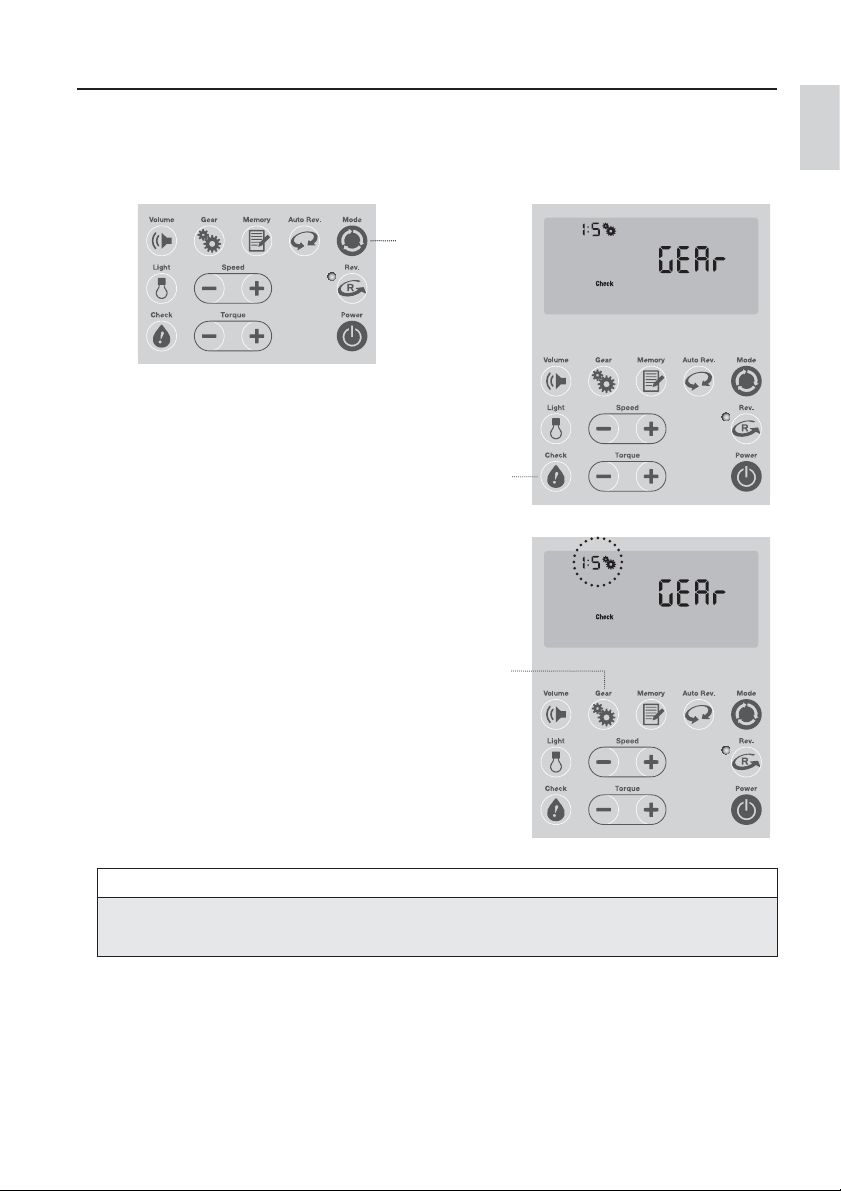
Select the Mode (NLZ E only)
1
Select the gear ratio of the attached handpiece
3
General Application Mode 1:5, 1:1, 4:1, 6:1
Rotary Endo Mode 1:1, 4:1, 6:1
Reciprocating Endo Mode 6:1 (Fixed)
Hold down the Check Key for more than 2
2
seconds to start up the Contra-Check. The “GEAr”
and the gear icon will start blinking after a short
beep sound.
1
2
3
English
NOTICE
Make sure that the correct gear ratio of the handpiece is selected before checking process, otherwise it will lead to
wrong results.
29
Page 31

Operation Procedure
After selecting the correct gear ratio, press the
4
Check Key again to start the checking process.
4
The motor automatically starts to operate at low speed and then accelerates to high speed to automatically
5
measure the state of the handpiece.
CAUTION
ŘStart the checking process while holding the handpiece. Checking, while leaving the handpiece on the handpiece
stand, may cause drop and damage of the handpiece and injury to user or patient.
ŘTo avoid any problems, care should be taken as the motor operates and rotates automatically.
ŘDuring the checking process, the system is designed to stop in an emergency by pressing any key on the control
panel. So, if you sense any danger, press any key on the control panel for an emergency stop.
NOTICE
Checking is possible with or without a bur/file.
Refrain from using burs which are not specified in the instruction of handpiece, otherwise it will lead to wrong
results.
Once the process is completed, "Fin" will be
6
displayed on the screen after a beep sound along
with the <Checking Result> displayed on the
screen as one of these cases:
30
Page 32

Operation Procedure
<Checking Result>
The check result is acceptable. After use, follow maintenance procedures as instructed in the
operation manual of the handpiece.
WARNING
If any abnormality, such as vibration, noise or overheating occurs, stop using the handpiece immediately even the
display shows the check result of "OK". We recommend repair or use new handpiece. Contact your Authorized
NSK Dealer.
The handpiece needs maintenance such as lubricating with oil.
WARNING
If you get the same result even after performing maintenance, the handpiece condition might have deteriorated.
We recommend repair or use new handpiece. Contact your Authorized NSK Dealer.
The handpiece is not functional.
WARNING
English
ŘIf you get the same result even after performing maintenance, the handpiece may be broken. We recommend
repair or use new handpiece. Contact your Authorized NSK Dealer.
ŘContinuing to use this handpiece should cause serious injuries due to abnormal heat generation.
The handpiece is damaged and motor cannot be activated in this situation!
Blinking
WARNING
ŘWhen you get this result, the handpiece is broken. Stop using the handpiece and change it to other handpiece.
We recommend repair or use new handpiece. Contact your Authorized NSK Dealer.
ŘContinuing to use this handpiece causes serious injuries due to abnormal heat generation.
31
Page 33

Operation Procedure
Press the Check Key again to return to the regular
7
screen.
7
CAUTION
ŘThere are cases where the motor works and the checking result is “OK” even though the bur or the file does not
rotate. In such case, the gears of the handpiece are worn out and damaged. Please contact your Authorized NSK
Dealer.
ŘContra-Check does not guarantee safety of handpieces in any environment.
Perform pre-use inspections ("3-9 Check before treatment") together with Contra-Check to ensure safety before
use.
NOTICE
Depending on the type of lubricator and maintenance unit, oil may build up inside the handpiece and have bad
impact on the checking process. If "OIL" or "NG" is displayed:
(1) Insert the purge nozzle (Refer to “2-1 List of
components”) into the rear of the handpiece, until
it clicks of a secure insertion and then insert the
tip of the air gun / syringe into the purge nozzle.
Purge nozzleAir gun / Syringe
(3) Perform the checking again.
(2) Run air with air gun / syringe for 30 seconds to
purge oil from inside the handpiece.
32
Page 34

Operation Procedure
4-5
Sound Volume (When the load exceeds the set torque limit value, Error etc.)
Press the Volume key.
1
Volume: High
Volume: Low
Volume: OFF
1
<List of Notifying Sound>
Type Notifying Sound
Rotary Endo Mode
Alarm sound for when the motor or a handpiece is overheating. Melody 3
When the motor/ handpiece is not functional, meaning the checking result of
the handpiece is “NG (blinking)”
Turning ON the power while pressing the foot pedal of the dental unit
When an error is generated: 1 short beep followed by 1 long beep.
When reaching 75% of the torque setting Melody 1
When reverse rotating Melody 2
A set of 3 short beeps continues to
sound.
English
CAUTION
Notifying sound will not be generated when the sound volume is set to OFF. Be aware of this while using the
system with the sound volume set to OFF.
33
Page 35

Operation Procedure
Last Memory Function
4-6
This function memorizes the last settings of each mode just before the power is turned OFF using the
Power key.
When the power is turned back ON, this function retains those settings of each mode.
The settings stored in this memory includes:
In <General Application Mode>
Gear ratio, rotation speed, light intensity, notifying sound volume, and memory number
In <Rotary Endo Mode>
Gear ratio, rotation speed, torque, auto reverse mode, light intensity, notifying sound volume, and
memory number
In <Reciprocating Endo Mode>
Notifying sound volume
Initializing Program (Restoring the Factory Setting)
4-7
This function allows to reset the programs of various settings (gear ratio, rotation speed, torque, auto
reverse mode) stored in the memory to the default factory setting.
By carrying out this function, various functional settings (such as air pressure for motor startup speed) as
described in “3-8 Changing the settings for various functions” will be reset to the default factory setting.
Turn OFF the power of the control unit.
1
While pressing down the Torque Key* (press +/-
2
keys simultaneously) (
Power Key (2) to turn ON the power. *Setting
key in case of NLZ.
1
1
), press and hold the
1
2-
2
2-
34
Page 36

Operation Procedure
With a short beep sound “rESEt” will be displayed
3
on the LCD Display. Press the Mode Key.
3
Press the Memory Key in the General Application Mode or Rotary Endo Mode.
5
When the memory sign stops blinking, initializing is completed.
blinking
With a long beep sound followed by a short beep
4
sound “Fin” will be displayed on the LCD Display.
With another short beep sound the display will
return to the last screen before the control unit
was turned OFF.
English
5
35
Page 37

Operation Procedure
<Default Factory Setting>
Mode Memory No. Gear ratio Rotation speed (min-1) Torque (N・cm) Auto reverse mode
1 1:5 200,000
2 1:1 40,000
General
Application
Mode
Rotary Endo
Mode
3 1:1 30,000
4 1:1 20,000
5 1:1 10,000
6 4:1 3,000
1 1:1 250 1.0 AUTO REVERSE FORWARD
2 1:1 250 1.5 AUTO REVERSE FORWARD
3 1:1 250 2.0 AUTO REVERSE FORWARD
4 1:1 250 3.0 AUTO REVERSE FORWARD
5 1:1 300 2.0 AUTO REVERSE FORWARD
6 1:1 1,000 3.0 AUTO STOP
NOTICE
If necessary, take a memo of the latest settings before initializing.
Overheat Prevention
4-8
Following functions detect a risk of overheating from motor current and rotation speed and then slows
down and stops motor rotation by activating the protection circuit to prevent incidents or failure due to the
overheat of the handpiece or the motor.
<Motor Overheat Prevention Function>
This function stops the rotation of the motor when detecting
overload or a risk of abnormal heating of the motor.
”Warning” and ”HE0” will be displayed along with alarm
sound and rotation of the motor will be slowed down.
Continued use will result in motor stop and Error Code “E8” will be displayed. (Refer to “7-1 Error Code”)
36
36
Page 38

Operation Procedure
<Contra-Restriction>
This function automatically slows down and stops the rotation
of the motor when the checking result through Contra-Check
is either “OIL” or “NG”.
”Warning” and ”HE1” will be displayed along with an alarm
sound and rotation of the motor will stop after approximately
2 seconds.
Error Code “E8” will be displayed once the motor stops. (Refer to “7-1 Error Code”)
NOTICE
Refer to “3-8 Changing the settings for various functions, Contra-Restriction”. Be aware that changing the setting
to “OFF” will deactivate this function.
<Contra-SAFE>
This is a function to stop the rotation of the motor when possible risk of overheat is detected with a 1:5
increasing handpiece. Error Code “EE” will be displayed once the motor stops. (Refer to “7-1 Error Code”)
NOTICE
Refer to “3-8 Changing the settings for various functions, Contra-SAFE”. Be aware that changing the setting to “No
stop” will deactivate this function.
WARNING
English
ŘNSK recommends to always activate both functions of " Contra-Restriction" and "Contra-SAFE" because using
these functions under “Off” or “No stop” may increase the probability or severity of overheating of defective or
poorly maintained handpieces.
Ř“Contra-Restriction” and “Contra-SAFE” functions are additional features for reducing the risk of handpiece
overheat but may not assure to maintain handpiece safe temperature.
ŘIf any abnormality, such as vibration, noise or overheating occurs, stop using the handpiece immediately and
contact your authorized NSK dealer.
37
37
Page 39

Post-use Maintenance
5
CAUTION
ŘFollow local rules, regulations, and guidelines regarding the reprocessing of devices.
ŘPerform the following cleaning and disinfection quickly after treatment (within 1 hour) to remove any residue.
ŘDo not perform steam sterilization the control unit, motor cord and AC adapter, AC power cord.
ŘDo not lubricate the motor. It may cause overheating and product failure.
ŘDo not use the following fluids to wipe, immerse or clean the product; strong/super acid water, strong acid/
alkaline chemicals, chlorine containing solutions, solvents such as benzine or thinner. It may cause color change
of resin part, or corrosion of the metal part of the NLZ Motor System.
ŘSteam sterilization is recommended for the product. The validity of other sterilization methods (such as plasma
sterilization or EOG sterilization) is not confirmed.
ŘFor details on maintenance of the handpiece, check the Operation Manual of the handpiece.
ŘDo not immerse the product in disinfectant or perform cleaning with an ultrasonic washer. Doing so may cause
product failure.
After each patient, maintain the product as follows.
Cleaning at point-of use (Motor)
5-1
Always wear protective gloves, a mask, and
1
protective goggles for safety purposes and to
minimize the risk of infection.
Remove the bur/file.
3
38
Turn off power by pressing the Power Key
2
2
Page 40

Wipe the exterior of the motor attached with the
4
handpiece clean using a cloth moistened with
disinfectant or ethanol with a concentration of 60-90%.
When using disinfectant, follow the instructions given by
the manufacturer of the disinfectant.
Use a state-sanctioned disinfectant with proven
bactericidal, fungicidal, and virucidal properties.
The following disinfectants can be used in the United
States and Canada.
Example) CaviCide
Metrex)
CaviCide® and CaviWipes® are registered trademarks of
Metrex Research, LLC.
®
, CaviWipes® (manufactured by
Post-use Maintenance
English
Remove the handpiece from the motor.
5
Carry the motor to the decontamination area.
7
Remove the motor from the motor cord.
6
39
Page 41

Post-use Maintenance
Cleaning, Disinfecting (Motor)
5-2
Wipe the exterior of the motor clean using a cloth moistened with disinfectant or ethanol with a
concentration of 60-90%.
ŘWhen using disinfectant, follow the instructions given by the
manufacturer of the disinfectant.
Use a state-sanctioned disinfectant with proven bactericidal,
fungicidal, and virucidal properties.
The following disinfectants can be used in the United States
and Canada.
Example) CaviCide
CaviCide
Metrex Research, LLC.
®
, CaviWipes® (manufactured by Metrex)
®
and CaviWipes® are registered trademarks of
40
Page 42

Post-use Maintenance
5-3
Packaging, Sterilizing, Drying and Storage (Motor)
Insert the motor into an FDA-approved sterilization pouch that conforms to ISO 11607-1, and seal
1
the pouch.
Perform steam sterilization with the following conditions.
2
Type Gravity Displacement Pre-Vacuum (Dynamic Air Removal)
Temperature 132°C 132°C
Full Cycle Time 15 min. or longer 4 min. or longer
Drying Time 30 min. or longer 30 min. or longer
Store the motor in a clean location without humidity.
3
CAUTION
ŘUse an FDA-approved steam sterilizer to perform sterilization.
ŘFollow local rules, regulations, and guidelines regarding the reprocessing of devices.
ŘImmediately after sterilization is complete (within 1 hour), remove the motor from the sterilizer. Failure to do so
may cause corrosion.
ŘDo not sterilize the control unit, main unit, AC adapter, AC power cord, motor cord.
ŘDo not lubricate the motor. It may cause overheating and product failure.
ŘDo not perform steam sterilization the product with other instruments even when it is in a pouch. This is to
prevent possible discoloration and damage to the product from chemical residue on other instruments.
ŘDo not heat or cool the product too quickly. Rapid change in temperature could cause damage to the motor.
ŘTo avoid product failure, do not use a sterilizer that exceeds a cycle temperature of 136°C, including the dry
cycle. In some sterilizers, the chamber temperature may exceed 136°C. Contact the sterilizer manufacturer for
detailed information about cycle temperatures.
ŘDo not touch the product immediately after steam sterilization as it will be very hot and must remain in a sterile
condition.
ŘSteam sterilization is recommended for the product. The validity of other sterilization methods (such as plasma
sterilization or EOG sterilization) is not confirmed.
ŘKeep the product in suitable atmospheric pressure, temperature, humidity, ventilation, and sunlight. The air
should be free from dust, salt and sulphur.
ŘSterility is not guaranteed after the sterility retention period specified by the manufacturer and seller of the
sterilization pouch has elapsed. If the sterility retention period has elapsed, perform sterilization again with a new
sterilization pouch.
English
NOTICE
NSK recommends Class B sterilizers as stated in EN 13060.
41
Page 43

Post-use Maintenance
C
Cleaning, Disinfecting (Control unit, motor cord)
5-4
Turn off the power switch of the main unit.
1
POWER
Wipe the exterior of the control unit and the motor
2
cord clean using a cloth moistened with disinfectant or
ethanol with a concentration of 60-90%.
When using disinfectant, follow the instructions given by the manufacturer of the disinfectant.
Use a state-sanctioned disinfectant with proven bactericidal, fungicidal, and virucidal properties.
The following disinfectants can be used in the United States and Canada.
Example) CaviCide
®
CaviCide
®
, CaviWipes® (manufactured by Metrex)
and CaviWipes® are registered trademarks of Metrex Research, LLC.
OUT
A
42
Page 44

Maintenance
6
6-1
Replacing the O-rings (Motor insert)
If a deteriorated O-ring makes it difficult to attach the
handpiece or causes water or air to leak, replace the
O-ring.
Using a needle or other pointed tool, remove defective
O-rings from the motor insert section, and fit new O-rings
into the O-ring grooves.
CAUTION
The blue O-ring is thinner than the other three O-rings.
When inserting new O-rings, make sure that they are
inserted in the correct grooves as shown in the figure.
English
O-ring (Blue)
O-ring (Black)
43
Page 45

Maintenance
Replacing the O-rings (Motor rear side)
6-2
If water or air leaks from the motor and motor cord
connection, replace the O-ring(s).
Using a needle or other pointed tool, remove the defective
O-ring(s) from the pipe at the motor rear section, and fit
new O-ring(s) into the O-ring groove(s).
(Air circuit: 2 pcs., water circuit: 2 pcs., coolant air
circuit: 1 pc.)
If an O-ring deteriorates, the following phenomena might occur:
-Water leakage, no water discharge
-Air leakage, no air discharge
-Generation of vibration
-Handpiece becomes difficult to attach or remove
NOTICE
Refer to “9-2 Spare Parts List” to identify the correct parts.
CAUTION
44
Page 46

Maintenance
6-3
Periodical Maintenance Checks
Every 3 months, perform periodical maintenance checks, referring to the check sheet below. If any
abnormalities are found, contact your Authorized NSK Dealer.
Points to check Details
Rotation
Rotate the motor/handpiece and check for abnormalities such as abnormal vibration, noise, and
overheating.
English
45
Page 47

Troubleshooting
7
Error Code
7-1
If the motor stops due to an abnormality such as a malfunction, overload, overheat, etc. it automatically
checks the state of all components, detects the cause of the abnormality and displays a warning and error
code on the LCD panel of the control unit.
Warning Description of Warning Action (Check / Remedy)
The handpiece has been used after the
HE1
HE0
* If you continue using the product, the motor will stop and error code “E8” will be displayed.
Error Code Description of error Action (Check / Remedy)
checking result through Contra-Check was
either “OIL” or “NG”.<Contra-Restriction> *
Overload or a risk of abnormal heating of the
motor detected. <Motor overheat prevention
function> *
E0 The motor shaft is locked. Check if the handpiece is connected properly.
E1 Detected over current in the circuit.
Detected a higher motor speed than the rated
E2
value.
E3 The motor drive IC generated an error signal.
E4 Detected high temperature of FET. Allow the unit to cool down and try again
E5 Detected an overvoltage input to the unit.
E6 Detected an overvoltage of an LED light. Check the LED light connection.
Detected a residual overvoltage when the
E7
motor was started.
A handpiece heat generation error was
detected.
E8
A motor heat generation error was detected. Leave the motor until it cools down.
E9 The motor does not start up. Check the motor connection.
EC Data cannot be saved to EPROM (Memory). Turn the power OFF and then ON again.
ED Signals from the sensor cannot be read. Check the connection of the motor to motor cord.
An increasing handpiece heat generation error
EE
was detected.
EF Detected an under-voltage input to the unit.
Perform maintenance of the handpiece and then
check the handpiece by <Contra-Check>.
Avoid overloading the handpiece with heavy cutting,
etc. and wait for the warning to disappear.
Avoid overloading the handpiece with continuous
heavy cutting, etc.
Press the foot pedal again to remove the error.
Check proper connection of AC adaptor and AC
power cord.
Wait for approx. 5 sec., then press the foot pedal
again.
If the error does not disappear, check if the motor
and motor cord are connected properly.
Perform maintenance of the handpiece, and then
check the handpiece by the Contra- Check.
Perform maintenance of the handpiece, and then
check the handpiece by the Contra- Check.
Check proper connection of AC adaptor and AC
power cord.
When an error code is displayed, stop operation of all devices immediately and perform the remedy
indicated in the table above. If the error code appears again, turn the power OFF and then ON again
and check if the error code disappears. If the error persists, the product may be broken. Contact your
Authorized NSK Dealer.
46
Page 48

Troubleshoting
7-2
Troubles and Actions
When trouble is found, check the following again before contacting your Authorized NSK Dealer. If none of
these is applicable or the trouble is not remedied even after action has been taken, a failure of this product
is suspected.
Troubles Cause Actions
The power Switch is OFF. Turn ON the power.
The AC adapter or AC power cord is
The LCD Display does not light.
The motor does not run.
The rotation speed of the motor
does not rise.
Beeps continue to sound when
turning ON the switch.
The LED does not light. Reached the end of life expectancy.
The motor heats up abnormally
during rotation.
Water leakage
Settings when the power is
turned ON are different from the
previous ones when turning off
the power.
not connected correctly.
Internal Fuse is blown, due to some
reason
The tubing, motor cord, AC adapter
or AC power cord is not connected
correctly.
The air pressure is not given, or not
proper from the dental unit.
The LCD Display shows an error
code.
The air pressure of the dental unit
is lower than the “Upper limit of the
air pressure”
You are stepping on the foot pedal
when turning on the power switch.
(Safety function)
Coolant air is not given, or not
proper from the dental unit.
The tubing, motor cord is not
connected correctly.
The power is turned OFF using the
main unit’s power switch.
Check the connection.
Contact your Authorized NSK
Dealer.
Check the connection.
Check the air pressure of the dental
unit.
Refer to the error code.
(Refer to “7-1 Error Code”)
Set the Upper limit of the air
pressure below the air pressure of
the dental unit.
(Refer to “3-8 Changing the settings
for various functions”)
Do not step the foot pedal, and turn
on the power switch.
Contact your Authorized NSK
Dealer.
Check the air pressure on the side
of the dental unit.
Check the connection. If it is
happening inside the control unit,
contact your Authorized NSK Dealer.
Previous settings will not be
retained when turning OFF the main
unit’s power switch. Turn OFF using
the control unit’s Power Key.
English
47
Page 49

Specifications
8
Specifications
8-1
Control Unit, Main Unit
Model NLZ E U (NE319): Endo function available
NLZ U (NE318): Endo function not available
Rated Input AC28V 50/60 Hz
Air Pressure 4bar (0.4MPa)
Dimensions Control Unit : W75.3 x D86.2 x H63.8 mm
Main Unit: W146 x D94.2 x H48 mm
Link Cable:1.0 m
Motor
Model NLZ
Rotation Speed 100 - 40,000 min
Max. Torque 4.2N・cm
Dimensions DØ22 x H68.8 mm
Optic White LED
Water Supply 65 mL/min or more
Chip Air Supply 1.5 L/min or more
Coolant Air Supply 6.5 NL/min or more
Use Environment 10 - 40
Transportation and Store Environment -10 - 50
-1
Temperature Humidity Pressure
℃
℃
AC Adaptor
Model NE180
Rated Input AC120V 50/60Hz 41VA
Rated Output AC28V 1.3A
Fuse Rating T1.6A/250V
Dimensions W100 x D178 x H64 mm
30 - 75%*
10 - 85%* 500 – 1,060hPa
*No Condensation
48
Page 50

Specifications
8-2
Symbol
This product can be sterilized in a steam sterilizer up to Max. 135°C.
Conforms to CE European Directive of "Medical device directive 93/42/EEC."
Manufacturer.
TUV Rhineland of North America is a Nationally Recognized Testing Laboratory (NRTL) in the United States
and is accredited by the Standards Council of Canada to certify electro-medical products with Canadian
National Standards
Consult operation instructions Class ll equipment Type B applied par
Caution, consult accompanying documents
Follow the waste of electric and electronic equipment (WEEE) Directive (2012/19/EU) for product and
accessory disposal
Marking on the outside of Equipment or Equipment parts that include RF transmitters or that apply RF
electromagnetic energy for diagnosis or treatment.
Serial number
English
Caution: U.S. Federal law restricts this device to be used by or on the order of a licensed dental professional.
GS1 DataMatrix for Unique Device ldentifier.
49
Page 51

After-sales Service
9
Warranty
9-1
NSK products are warranted against defects in manufacturing, workmanship and materials. NSK reserves the
right to analyze and determine the cause of any problem. Warranty is voided should the product not be used
in accordance with this manual or has been tampered with by unqualified personnel or has had non NSK parts
installed. Replacement parts are available for seven years beyond discontinuation of the model.
Spare Parts List
9-2
Model Order Code Remarks
O-ring Set Y1003728 For the motor insert section (Black: 3pcs., Blue:1 pc.)
O-ring D0312010050 For the motor rear side
NLZ E1152051 Motor (without a motor cord)
NLZ CD E1152061 Motor cord (1.8m)
Purge Nozzle Z1259080 NLAC (120V) Y141133 AC adapter (common with NLX nano)
AC Power Cord U438550 NLZ U BRACKET Z1322 A bracket used for mounting to the main unit.
NLZ E U U1142002 NLZ E control unit, main unit
NLZ U U1141002 NLZ control unit, main unit
50
Page 52

Afrter-sales Service
9-3
9-4
Option Parts List
Model Order Code Remarks
NLZ Endo C1130 6:1 Reduction Endodontic Contra Angle Handpiece
NLZ STAY Z1321 A stay used for mounting to the control unit.
NLZ MOUNTING PLATE Z1323 A plate used for mounting to the control unit.
NLZ CDL E1152062 Motor cord (2.2m)
Disposing product
In order to avoid the health risks of operators handling the disposal of medical equipment, as well as the
risks of environmental contamination caused thereof, a surgeon or a dentist is required to confirm the
equipment is sterile. Ask specialist firms who are licensed to dispose of specially controlled industrial
wastes, to dispose the product for you.
English
51
Page 53

EMC Information
10
Guidance and manufacturer’s declaration - Electromagnetic Emissions
The product is intended for use in the electromagnetic environment specified below. The customer or the user of the product should
assure that it is used in such an environment.
Emissions test Compliance Electromagnetic environment – guidance
RF emissions
CISPR11/EN55011
RF emissions
CISPR11/EN55011
Harmonic emissions
EN/IEC61000-3-2
Voltage fluctuations/flicker
emissions
EN/IEC61000-3-3
Guidance and manufacturer’s declaration - Electromagnetic Immunity
The product is intended for use in the electromagnetic environment specified below. The customer or the user of the product should
assure that it is used in such an environment.
Immunity test IEC/EN60601 test level Compliance level Electromagnetic environment - guidance
Electrostatic discharge(ESD)
EN/IEC61000-4-2
Electrical fast transient/burst
EN/IEC61000-4-4
Surge
EN/IEC61000-4-5
Voltage dips, short
interruptions and voltage
variations on power supply
input lines
EN/IEC61000-4-11
Power frequency
(50/60Hz) magnetic field
EN/IEC61000-4-8
NOTE: ‘Ut’ is the AC mains voltage prior to application of the test level.
Group 1 The product uses RF energy only for its internal function. Therefore, its
Class B The product is suitable for use in all establishments, including domestic
No applicable
No applicable
±(2,4)6kV contact
±(2,4)8kV air
±2kV for power supply lines
±1kV for input/output lines
±1kV line(s) to line(s)
±2kV line(s) to earth
<5% Ut
(>95% dip in Ut)
for 0.5 cycles
40% Ut
(60% dip in Ut)
for 5 cycles
70% Ut
(30% dip in Ut)
for 0.5 cycles
<5% Ut
(<95% dip in Ut)
for 5 sec
3 A/m 3 A/m Power frequency magnetic fields should
(Electromagnetic Compatibility Information)
RF emissions are very low and are not likely to cause any interference in
nearby electronic equipment.
establishments and those directly connected to the public low-voltage
power supply network that supplies buildings used for domestic
purposes.
±(2,4)6kV contact
±(2,4)8kV air
±2kV for power supply lines
±1kV for input/output lines
±1kV line(s) to line(s)
±2kV line(s) to earth
<5% Ut
(>95% dip in Ut)
for 0.5 cycles
40% Ut
(60% dip in Ut)
for 5 cycles
70% Ut
(30% dip in Ut)
for 0.5 cycles
<5% Ut
(<95% dip in Ut)
for 5 sec
Floors should be wood, concrete or
ceramic tile. If floors are covered with
synthetic material, the relative humidity
should be at least 30%.
Mains power quality should be that
of a typical commercial or hospital
environment.
Mains power quality should be that
of a typical commercial or hospital
environment.
Mains power quality should be that
of a typical commercial or hospital
environment. If the user of the product
requires continued operation during power
mains interruptions, it is recommended
that the product be powered from an
uninterruptible power supply or a battery.
be at levels characteristic of a typical
location in a typical commercial or hospital
environment.
52
Page 54

EMC Information
(Electromagnetic Compatibility Information)
Guidance and manufacturer’s declaration - Electromagnetic Immunity
The product is intended for use in the electromagnetic environment specified below. The customer or the user of the product should
assure that it is used in such an environment.
Immunity test IEC/EN60601 test level Compliance level Electromagnetic environment – guidance
Conducted RF
EN/IEC61000-4-6
Radiated RF
EN/IEC61000-4-3
NOTE 1: At 80MHz and 800MHz, the higher frequency range applies.
NOTE 2: These guidelines may not apply in all situations. Electromagnetic propagation is affected by absorption and reflection from
structures, objects and people.
a: Field strengths from fixed transmitters, such as base stations for radio (cellular/cordless) telephones and land mobile radios, amateur
radio, AM and FM radio broadcast and TV broadcast cannot be predicted theoretically with accuracy. To assess the electromagnetic
environment due to fixed RF transmitters, an electromagnetic site survey should be considered. If the measured field strength in the
location in which the product is used exceeds the applicable RF compliance level stated above, the product should be observed to
verify normal operation. If abnormal performance is observed, additional measures may be necessary, such as reorienting or relocating
the product.
b: Over the frequency range 150kHz to 80MHz, the field strength should be less than 3V/m.
3Vrms
150kHz to 80MHz
3V/m
80MHz to 2.5GHz
3Vrms Portable and mobile RF communications
3V/m
equipment should be used no closer to
any part of the product, including cables,
than the recommended separation
distance calculated from the equation
applicable to the frequency of the
transmitter.
Recommended separation distance
d=1.2 √P
d=1.2 √P 80MHz to
800MHz
d=2.3 √P 800MHz to
2.5GHz
Where P is the maximum output power
rating of the transmitter in watts (W)
according to the transmitter manufacturer,
and (d) is the recommended separation
distance in meters (m). Field strengths
from fixed RF transmitters as determined
by an electromagnetic site survey(a)
should be less than the compliance level
in each frequency range(b). Interference
may occur in the vicinity of equipment
marked with the following symbol:
English
53
Page 55

EMC Information
Cables and accessories Maximum length Complies with
Link cable 1.0m
AC adaptor cord
(Secondary side)
AC adaptor cord
(Primary side)
Motor cord 2.2m
Recommended separation distances between portable and mobile RF communications equipment and the product
The product is intended for use in an electromagnetic environment in which radiated RF disturbances are controlled. The customer or
the user of the product can help prevent electromagnetic interference by maintaining a minimum distance between portable and mobile
RF communications equipment (transmitters) and the product as recommended below, according to the maximum output power of the
communications equipment.
Rated maximum output power
of transmitter W
0.01 0.12 0.12 0.23
0.1 0.38 0.38 0.73
1 1.2 1.2 2.3
10 3.8 3.8 7.3
100 12 12 23
For transmitters rated at a maximum output power not listed above, the recommended separation distance “d” in meters (m) can be
estimated using the equation applicable to the frequency of the transmitter, where “P” is the maximum output power rating of the
transmitter in watts (W) according to the transmitter manufacturer.
NOTE 1: At 80MHz and 800MHz, the higher frequency range applies.
NOTE2 : These guidelines may not apply in all situations. Electromagnetic propagation is affected by absorption and reflection from
structures, objects and people.
(Electromagnetic Compatibility Information)
(Unshielded)
5.0m
(Unshielded)
2.0m
(Unshielded)
(Unshielded)
Separation distance according to frequency of transmitter m
150MHz to 80MHz
d=1.2 √P
RF emissions, CISPR11, EN55011 Class B / Group 1
Electrostatic discharge (ESD): EN/IEC61000-4-2
Electrical fast transient/burst: EN/IEC61000-4-4
Surge: EN/IEC61000-4-5
Voltage dips, short interruptions and voltage variations on power supply input
lines:
EN/IEC61000-4-11
Power frequency(50/60Hz) magnetic field: EN/IEC61000-4-8
Conducted RF: EN/IEC61000-4-6
Radiated RF: EN/IEC61000-4-3
80MHz to 800MHz
d=1.2 √P
800MHz to 2.5GHz
d=2.3 √P
54
Page 56

Table des matières
Français
1. Introduction ................................................ 56
1-1 Description ...............................................................56
1-2 Utilisateur et indications d’emploi ..............................56
1-3 Précautions relatives à la manipulation et à ...............57
l’utilisation de l’unité
1-4 Classe d'équipement ................................................60
2. Composants ................................................61
2-1 Liste des composants ...............................................61
2-2 Noms des pièces de l’unité de commande et de ........62
l’unité principale
3. Préparatifs avant l’utilisation ....................... 66
3-1 Installation de l’unité principale et de l’unité de ..........66
commande
3-2 Branchement du tube ...............................................67
3-3 Branchement du cordon moteur ................................68
3-4 Branchement de l’adaptateur d’alimentation c.a. .......68
3-5 Branchement du cordon d’alimentation c.a. ..............69
3-6 Branchement/débranchement du moteur/cordon ........69
moteur
3-7 Branchement/débranchement du moteur et de la ......70
pièce à main (option)
3-8 Modification des réglages des diverses fonctions ........ 71
3-9 Vérification avant le traitement ..................................75
4. Procédure d’utilisation ................................76
4-1 Mode Application générale ........................................ 77
4-2 Mode Endodontique rotatif (NLZ E seulement) ............78
4-3 Mode Endodontique alternatif (NLZ E seulement) ........82
4-4 Fonction Contra-Check .............................................83
4-5 Volume sonore .........................................................88
(charge dépassant la valeur limite du couple, erreur,
etc.)
4-6 Fonction de la dernière mémoire ...............................89
4-7 Programme de réinitialisation ....................................89
(Restauration des valeurs de l’usine– par défaut)
4-8 Protection contre la surchauffe ..................................92
5. Entretien après usage .................................94
5-1 Nettoyage des composants de traitement (moteur) .....94
5-2 Nettoyage et désinfection (moteur).............................96
5-3 Emballage, stérilisation, ...........................................97
séchage et entreposage (moteur)
5-4 Nettoyage et désinfection ..........................................98
(unité de commande, cordon moteur)
6. Entretien ...................................................100
6-1 Remplacement des joints toriques (prise du moteur) ...99
6-2 Remplacement des joints toriques ...........................100
(partie arrière du moteur)
6-3 Inspection d’entretien périodique .............................100
7. Dépannage ...............................................101
7-1 Code d’erreur .........................................................101
7-2 Pannes et mesures correctives ................................102
8. Spécifications ...........................................104
8-1 Spécifications .........................................................104
8-2 Symbole.................................................................105
9. Service après-vente ..................................106
9-1 Garantie .................................................................106
9-2 Liste des pièces de rechange ..................................106
9-3 Liste des pièces en option .......................................107
9-4 Mise au rebut du produit .........................................107
10. Données de CEM ......................................108
(compatibilité électromagnétique)
Français
55
Page 57

Introduction
1
ATTENTION
Les lois fédérales stipulent que seuls les professionnels des soins dentaires agréés sont autorisés à faire usage de
cet instrument ou d’en superviser l’utilisation.
Nous vous remercions d’avoir acheté un système de moteur NSK NLZ E / NLZ.
Ce système peut être raccordé à une pièce à main pneumatique existante pour la doter d’un micromoteur
électrique sans balai avec DEL intégrée.
Veuillez lire attentivement ce manuel d’utilisation avant d’utiliser ce système. Prenez connaissance des
instructions et des directives d’entretien pour accroître la durée utile du système. Conservez ce manuel
d’utilisation afin de pouvoir vous y référer ultérieurement.
Description
1-1
Les systèmes de moteur NLZ sont proposés en deux modèles.
Le système NLZ comprend l’unité principale, l’unité de commande (sans mode endodontique) et le moteur.
Le système NLZ E comprend l’unité principale, l’unité de commande (avec mode endodontique) et le
moteur.
Option
Utilisateur et indications d’emploi
1-2
Utilisateur:
Les lois fédérales stipulent que seuls les professionnels des soins dentaires agréés sont autorisés à faire
usage de cet instrument ou d’en superviser l’utilisation.
Indications d’emploi
Le système de moteur NLZ peut être utilisé par les dentistes pour l’exécution de traitements de
restauration dentaire, et de traitements prophylactiques et endodontiques.
NLZ Endo est conçu pour être utilisé par des professionnels spécialisés en dentisterie pour réaliser des
procédures endodontiques.
56
Page 58

Introduction
1-3
Précautions relatives à la manipulation et à l’utilisation
ŘLire attentivement les précautions, et utiliser seulement l’instrument aux fins pour lesquelles il est destiné
ou selon les instructions.
ŘLes instructions de sécurité ont pour but d'éviter tout danger potentiel risquant de provoquer des
blessures ou d’endommager l’instrument. Les instructions de sécurité sont répertoriées en fonction de
l’importance des risques.
Classe Niveau de risque
MISE EN GARDE
Danger qui risque d’entraîner de graves blessures ou d’endommager
l’instrument si les instructions de sécurité ne sont pas observées.
Danger qui risque d’entraîner des blessures légères à modérées ou
ATTENTION
d’endommager l’instrument si les instructions de sécurité ne sont pas
observées.
Données sur les spécifications générales du produit visant à éviter tout
AVIS
mauvais fonctionnement de l’instrument ou une dégradation de son
rendement.
MISE EN GARDE
ŘNe pas démonter, régler ni modifier le moteur ou la pièce à main, à moins que cela ne soit recommandé par
NSK dans le présent manuel d’utilisation.
ŘNe pas manipuler le cordon d’alimentation c.a. ni tout autre composant du système avec des mains humides/
mouillées. Toucher des appareils électriques avec des mains mouillées peut causer des décharges électriques.
ŘÉviter toute éclaboussure d’eau sur l’unité de commande ou à proximité. Cela risquerait de provoquer un court-
circuit, un incendie et/ou une décharge électrique.
ŘL’instrument ne doit pas être soumis à des impacts. Ne pas laisser l’instrument tomber au sol. Cela pourrait
entraîner une décharge électrique ou une défaillance de l’instrument.
ŘNe pas utiliser cet instrument à proximité de patients qui ont un stimulateur cardiaque (Pacemaker). Cela
pourrait nuire au bon fonctionnement du stimulateur cardiaque.
ŘGarder cet instrument à bonne distance de substances explosives ou inflammables. De plus, ne pas utiliser
cet instrument pour traiter des patients ou à proximité de patients dont l’anesthésie est assurée par un gaz
inflammable, comme l’oxyde de diazote.
ŘSi l’instrument surchauffe ou émet une odeur de fumée, couper immédiatement l’alimentation, débrancher le
cordon d’alimentation (en tirant sur la fiche et non sur le cordon), puis communiquer avec un détaillant NSK
autorisé.
ŘLorsque cet équipement est utilisé à proximité d'un autre équipement ou dans un ensemble d’équipements
superposés, tous les équipements en question doivent être surveillés de près pour s'assurer qu'ils fonctionnent
normalement.
ŘRaccorder la pièce à main au moteur, puis la faire fonctionner avant tout traitement pour déceler toute
vibration du moteur, tout bruit ou tout signe de surchauffe. Si la pièce à main semble mal fonctionner, arrêter
immédiatement de l’utiliser, puis communiquer avec votre détaillant NSK autorisé (se reporter à la section 3-9–
Vérification avant le traitement).
Français
57
Page 59

Introduction
ŘSi l’instrument présente un mauvais fonctionnement, cesser immédiatement de l’utiliser, puis communiquer
avec votre détaillant NSK autorisé.
ŘSi l’instrument n’est pas utilisé pendant une longue période, faire tourner le moteur pour déceler la présence de
bruits, de vibrations ou de surchauffe avant de l’utiliser.
<Moteur et pièces à main (Option)>
ŘImmédiatement après le traitement (au plus, dans l’heure qui suit), procéder à l’entretien des instruments, puis
ranger le moteur et la pièce à main. Le non-respect des procédures d'entretien appropriées relatives au moteur
et à la pièce à main peut entraîner la surchauffe du système, risquant ainsi de provoquer des infections, des
brûlures et la défaillance de l'instrument. Observer les procédures d’entretien indiquées dans le présent manuel
et dans le manuel d’utilisation de la pièce à main.
ATTENTION
ŘLa sécurité du patient passe avant tout.
ŘCet instrument a été conçu pour être utilisé uniquement pour l'exécution de traitements dentaires par un
personnel qualifié en la matière. Cet instrument ne doit pas être utilisé pour une chirurgie buccale, la pose
d’implants ni pour des travaux de laboratoire dentaire.
ŘCet instrument peut seulement être utilisé par des dentistes, et dans un centre dentaire ou dans un établissement
de soins, comme un hôpital.
ŘCet instrument doit être utilisé dans une clinique dentaire, un hôpital ou tout autre établissement de soins
dentaires.
ŘIl incombe à l’utilisateur final d’user de son jugement lors de l’utilisation de cet instrument pour traiter un patient.
ŘL’utilisateur final est responsable de l’utilisation, de l’entretien et de l'inspection de l’instrument.
ŘUtiliser seulement cet instrument dans les environnements spécifiés. Dans le cas contraire, une défaillance
pourrait survenir (se reporter à la section 8-1– Spécifications).
ŘLes utilisateurs et toutes les personnes à proximité doivent porter des lunettes de protection et un masque lors
de l’utilisation d’une pièce à main.
ŘUtiliser uniquement l’adaptateur c.a. et le cordon d’alimentation c.a. fournis avec l’instrument. Ne jamais utiliser
un autre adaptateur c.a. Cela pourrait entraîner une défaillance de l’instrument.
ŘLe cordon d’alimentation c.a. est le moyen le plus pratique de couper l’alimentation. S’assurer que le cordon
d’alimentation c.a. peut être retiré facilement sans délai en cas d’urgence. Ne placer aucun article à moins de 15
cm du cordon d’alimentation c.a.
ŘLorsque l’unité de commande, l’unité principale ou l’adaptateur c.a. semblent souillés de poussière, couper
l’alimentation (OFF), enlever la poussière avec un chiffon humide bien essoré, puis assécher les composants au
moyen d’un chiffon sec.
ŘNe pas utiliser les fluides suivants pour nettoyer, immerger ou laver le système : eau acide, acide fort, produits
à base de produits alcalins, solutions à base de chlore, solvants (benzène ou diluant à peinture) (se reporter à la
section 5– Entretien après usage).
ŘProcéder régulièrement à des vérifications des fonctions et à des inspections d’entretien (se reporter à la section
6.3– Inspection d’entretien périodique).
58
Page 60

Introduction
ŘCet instrument est répertorié comme étant un équipement électrique de catégorie médicale. La compatibilité
électromagnétique (CEM) est indiquée dans les documents fournis. L’installation et l’utilisation de cet
instrument exigent des précautions particulières conformément aux renseignements fournis sur la compatibilité
électromagnétique (se reporter à la section 10– Données de CEM (compatibilité électromagnétique).
ŘLes dispositifs de communication à radiofréquence portatifs et mobiles peuvent compromettre le bon
fonctionnement de l’équipement médical électrique. Ne pas utiliser de dispositifs à radiofréquence à proximité
de l’appareil.
ŘUtiliser uniquement des composants autorisés. L’utilisation d’autres pièces d'équipement peut compromettre le
rendement de l’instrument en matière de compatibilité électromagnétique.
ŘS’assurer que chaque composant est bien raccordé. Des branchements lâches/inappropriés peuvent provoquer
un mauvais fonctionnement, une défaillance de la DEL intégrée et des fuites d’air ou d’eau.
ŘLe cordon d’alimentation c.a livré avec l’instrument fait 2 mètres de long. Enrouler et placer le cordon de façon
sécuritaire afin d’éviter que les patients ne trébuchent en passant à proximité.
<Unité de commande, unité principale>
ŘAu moment de débrancher le cordon d’alimentation c.a., le cordon moteur ou tout autre cordon, empoigner la
fiche du cordon pour débrancher ce dernier. Le fait de tirer directement sur le cordon peut favoriser l'étirement
du conducteur dans la gaine et entraîner une défaillance.
ŘAu moment d’installer l’unité de commande, le moteur ou tout autre composant, prévoir un espace suffisant
pour éviter de plier ou de tortiller le tube ou le cordon.
ŘNe pas stériliser l’unité de commande, l’unité principale, l’adaptateur c.a., le cordon d’alimentation c.a. et le
cordon moteur.
<Moteur et pièces à main (Option)>
ŘLe couple de sortie varie en fonction du type de pièce à main raccordée au moteur, aux conditions d’utilisation
et à d’autres facteurs. S’assurer d’utiliser une pièce à main NSK (se reporter à la section 4-4– Fonction ContraCheck). L’utilisation d’une pièce à main d’un autre fabricant peut entraîner des défaillances, comme une
disparité entre le couple préréglé et le couple de sortie.
ŘS’assurer que le moteur s’est arrêté de tourner avant de manipuler la pièce à main. Le branchement ou le
débranchement de la pièce à main alors que le moteur tourne peut causer des blessures ou endommager la
pièce à main.
ŘNe pas orienter le faisceau lumineux du moteur et de la pièce à main directement dans les yeux du patient ou
de l’opérateur. Cela pourrait causer des lésions oculaires.
ŘLe moteur est livré dans un emballage non stérile; par conséquent, il doit être stérilisé à la vapeur (autoclave)
avant d’être utilisé.
ŘNe pas lubrifier le moteur. Cela pourrait entraîner une surchauffe et endommager l’instrument.
ŘPrévoir une source d’air comprimé exempte d’humidité et de poussière. Un apport d’humidité dans le jet d’air
pourrait entraîner une défaillance de l’instrument ou une surchauffe.
ŘRaccorder seulement un tube de type 2 (Midwest à 4orifices) conforme à la norme ISO 9168, ou de type 3
(conforme à la norme ISO relative à un connecteur à 4 orifices avec lampe).
ŘS’assurer d’utiliser de l’air de refroidissement. Autrement, le moteur et la surface de la pièce à main pourraient
atteindre une température de 51°C ou plus.
Français
59
Page 61

Introduction
AVIS
Ř
Pendant l’utilisation, le moteur et le cordon moteur peuvent compromettre le bon fonctionnement
d’ordinateurs et de câbles réseau situés à proximité. Un appareil radio situé à proximité pourra
également émettre des bruits parasites.
Ř
Pour les activités quotidiennes, utiliser la touche d’alimentation (Power Key) pour mettre sous
tension/hors tension l’appareil. Si le système n’est pas utilisé pendant une longue période ou s’il
présente un mauvais fonctionnement, appuyer sur la touche d’alimentation pour éteindre l’appareil
(OFF), débrancher le cordon d’alimentation de l’unité principale, puis vidanger l’eau de l’unité
principale, du tube et du cordon moteur.
Ř
Pour obtenir plus de détails sur la manipulation de la pièce à main, se reporter au manuel d’utilisation
de la pièce à main.
Ř
Seul un personnel d'entretien autorisé peut procéder à l’inspection du produit en suivant les
instructions du manuel d’entretien. Confier l’appareil à un détaillant NSK autorisé au besoin.
Ř
L’utilisation de cet appareil ne requiert aucune formation spéciale.
Ř
Vidanger l’eau de l’unité principale, du tube et du cordon moteur si l’appareil n’est pas utilisé
pendant une longue période.
Classe d'équipement
1-4
ŘType de protection contre les décharges électriques:
- Équipement de classe II
ŘNiveau de protection contre les décharges électriques:
- Pièce appliquée de type B:
(pièces appliquées: moteur, pièce à main)
ŘMéthode de stérilisation ou de désinfection recommandée par le fabricant:
- Se reporter à la section 5-3– Emballage, stérilisation, séchage et entreposage (moteur)
ŘNiveau de protection contre l’infiltration d’eau décrit dans l’édition courante du document IEC 60529:
- Unité de commande: IPX0 (non protégé)
ŘNiveau de sécurité de l’application en présence d’un mélange anesthésique inflammable avec de l’air, de
l’oxygène ou de l’oxyde d’azote :
- Équipement qui NE PEUT ÊTRE utilisé en présence d’un mélange anesthésique inflammable avec de l’air,
de l’oxygène ou de l’oxyde d’azote :
ŘMode de fonctionnement :
- Fonctionnement à intermittence (EN MARCHE : 3 min., À L’ARRÊT : 10 min.)
60
Page 62

Composants
2
2-1
Liste des composants
1
5
9
N° Nom de la pièce Quantité Remarque
1 Unité de commande 1
2 Unité principale 1
3 Moteur 1 4 Cordon moteur 1 Longueur du cordon : 1,8m
5 Buse de purge 1
6 Adaptateur c.a. 1 Longueur du cordon : 5m
Cordon d'alimentation
7
c.a.
8 Jeu de joints toriques 1jeu
9 Support de montage 1 Pour l’unité principale
Vis et écrous de
10
montage
11 Attache de câble 2 Pour fixer le câble de données
2
6
10 11
L’unité de commande et l’unité principale sont raccordées par un
câble de données.
Pour la purge de l’excédent d’huile
(compatible avec les pièces à main conformes à la norme ISO 3964)
1 Longueur du cordon : 2m
Pièces de rechange
Pour le joint rapporté du moteur (noir : 3 pièces, bleu : 1 pièce)
Pour la tubulure de la partie arrière du moteur (noir : 5 petites pièces)
1jeu
M5x30 screw (2 pcs.), M4x30 screw (2 pcs.), M4 flat head screw (2
pcs.), M5 nut (2 pcs.), M4 nut (2 pcs.)
3
7
4
Français
8
61
Page 63

Composants
Noms des pièces de l’unité de commande et de l’unité principale
2-2
Câble de données
(longueur du câble : 1m)
Afficheur à ACL
Panneau de
commande
< Unité de commande> < Unité principale >
Commutateur
d’alimentation
Connecteur du cordon
moteur
Connecteur de tube
Connecteur du cordon
d'alimentation c.a.
62
Page 64

Afficheur à ACL et panneau de commande de l’unité de commande
< NLZ E >
F3G2H
E
D
C
Composants
I
A
B
Français
< NLZ >
8
7
6
5
4
F3G
E
D
C
8
7
6
9
10
11
1
A
B
10
11
5
4
2
1
63
Page 65

Composants
N° Touche Nom
1
POWER
(Touche
d’alimentation)
2
MEMORY
(Touche de
mémoire)
TORQUE
(Touche de
couple) (NLZ
3
E)
SETTING
(Touche de
réglage) (NLZ)
Affichage
Fonction
Appuyer une fois pour mettre sous tension (ON). Lorsque
-
l’unité est sous tension, enfoncer la touche pendant plus
de deux secondes pour éteindre l’unité.
En General Application Mode :
La vitesse du moteur peut être réglée entre 100 et
40 000 min-1.
G
En Rotary Endo Mode :
La vitesse du moteur peut être réglée entre 100 et
6 000 min-1.
* Les modifications de la valeur d’affichage sont fonction
du rapport de vitesse.
Lorsque le rapport de vitesse est réglé par chaque
pression de cette touche, vous pouvez régler le couple.
Rotary Endo Mode
Rapport de
B
vitesse
Plage de couple
(N·cm)
1:1 0,3 - 3,0 0,1
4:1 0,8 - 6,0 0,4
6:1 1,0 - 6,0 1,0 - 1,2:0,2
Modifier le réglage en suivant les instructions de la section
3-8 – Modification des réglages de diverses fonctions.
Modifier le réglage en suivant les instructions de la section
3-8 – Modification des réglages de diverses fonctions.
Incrément (N·cm)
1,2 - 6,0:0,6
En General Application Mode :
La vitesse du moteur peut être réglée entre 100 et
40 000 min-1.
4
SPEED
(Touche de
vitesse)
A
En Rotary Endo Mode :
La vitesse du moteur peut être réglée entre 100 et
6 000 min-1.
* Les modifications de la valeur d’affichage sont fonction
du rapport de vitesse.
5
(Touche de
vérification)
CHECK
Vérifier l'état de la pièce à main en suivant les instructions
C
de la section 4-4 – Fonction Contra-Check.
Régler l’intensité lumineuse (Élevée·Modérée·Réduite·Zéro
(OFF))
6
LIGHT
(Touche
d'éclairage)
Chaque pression de la touche permet de régler l’intensité
D
de OFF -> intensité 1 -> intensité 2 -> intensité 3, puis
de nouveau à OFF (éteint).
* La lampe peut être allumée pendant 5 secondes en
appuyant sur la touche lorsque le moteur est à l’arrêt.
64
Page 66

Composants
N° Touche Nom
7
VOLUME
(Touche de
volume)
8
GEAR (Touche
de rapport)
AUTO. REV.
(Touche
d’inversion
9
automatique)
(NLZ E)
*Mode
Endodontique
rotatif
seulement
MODE
(Touche de
mode)(NLZ E)
10
SETTING
MODE
(Touche de
réglage du
mode)(NLZ)
Affichage
Fonction
Régler le volume des alertes d'atteinte du couple maximal
préréglé ou lorsqu’une erreur survient (Haut·Réduit·OFF).
Chaque pression de la touche permet de régler le volume
de OFF -> volume 1 -> volume 2 ->, puis de nouveau à
E
OFF (éteint).
ATTENTION
Lorsque le volume est réglé à OFF (sourdine), aucune
alarme n’est émise. On doit être prudent lorsque le
volume du système est désactivé (OFF).
Chaque pression de la touche permet de modifier le
rapport de vitesse de l’unité
de 1:5 -> 1:1 -> 4:1 -> 6:1 ->, puis de nouveau à 1:5 –
F
en mode Application générale.
de 1:1 -> 4:1 -> -> 6:1 ->, puis de nouveau à 1:1 – en
mode Endodontique rotatif.
Chaque pression de la touche permet d’alterner entre les
modes suivants : AUTO STOP (ARRÊT AUTOMATIQUE)
-> AUTO REVERSE STOP (INVERSION AUTOMATIQUE
– ARRÊT) -> AUTO REVERSE FORWARD (INVERSION
AUTOMATIQUE – ROTATION NORMALE), puis de nouveau
à AUTO STOP (ARRÊT AUTOMATIQUE).
H
AUTO STOP
(ARRÊT
AUTOMATIQUE)
AUTO
REVERSE STOP
(INVERSION
AUTOMATIQUE
- ARRÊT)
Alterne entre les 3 modes d’application ci-dessous
Mode Application
I
générale :
Aucun affichage
Modifier le réglage en suivant les instructions de la section
3-8 – Modification des réglages de diverses fonctions.
Mode
Endodontique
rotatif :
Français
AUTO REVERSE
FORWARD
(INVERSION
AUTOMATIQUE
- ROTATION
NORMALE)
Mode Endodontique
alternatif :
11
REV. (Touche
d’inversion)
Le sens de rotation peut être inversé au moyen de cette
-
touche. La DEL intégrée s’allume en mode de rotation
inverse.
65
Page 67

Préparatifs avant l’utilisation
3
ATTENTION
S’assurer que chaque composant est bien raccordé. Des branchements lâches/inappropriés peuvent provoquer un
mauvais fonctionnement, une défaillance de la DEL intégrée et des fuites d’air ou d’eau.
Installation de l’unité principale et de l’unité de commande
3-1
Fixer l’unité principale à l’unité dentaire en
1
utilisant les vis fournies, comme le montre
l’illustration ci-dessous :
Vis M4x30 et
M5x30 avec
écrou (inclus)
Vis à tête plate M4
(incluse)
Enrouler le câble de données, puis utiliser une attache de câble.
3
2
Placer l’unité de commande sur le plateau de
l’unité dentaire.
Attache
de câble
(incluse)
S’il est nécessaire d’installer l’unité comme le montre l’illustration ci-dessous, il faut se procurer des pièces
4
en option (se reporter à la section 9-3 – Liste des pièces en option).
Exemple d’installation d’une unité NLZ
avec un support « STAY »
Exemple d’installation d’une unité
NLZ avec PLAQUE DE MONTAGE
66
Page 68

Préparatifs avant l’utilisation
ATTENTION
ŘGarder l’unité principale à bonne distance de l’eau.
ŘL’unité de commande est dotée d’un panneau d’affichage à ACL. Placer l’unité de façon à ce que l’opérateur
puisse consulter l’afficheur.
ŘNe pas plier le tube en fixant l’unité principale en place. Prévoir un espace suffisant pour acheminer le tube afin
d’éviter tout pincement.
Français
3-2
Branchement du tube
Aligner le tube avec l’unité dentaire et le connecteur de tube situé
sur la partie arrière de l’unité principale (1). L’insérer à fond, puis
le serrer solidement (2).
①
IN
OUT
AC28V
POWER
ATTENTION
ŘS’assurer que le tube ne contient ni air ni eau au moment de le fixer à l’unité principale.
ŘPrévoir une source d’air comprimé exempte d’humidité et de poussière. Un apport d’humidité dans le jet d’air
pourrait entraîner une défaillance de l’instrument ou une surchauffe.
ŘAu moment de brancher le connecteur de tube, visser l'écrou manuellement. Éviter d’entrecroiser le tube.
ŘRaccorder seulement un tube de type 2 (Midwest à 4orifices) conforme à la norme ISO 9168, ou de type 3
(conforme à la norme ISO relative à un connecteur à 4 orifices avec lampe).
ŘExigence relative à l’air : sec, exempt de contaminant et d’huile. Utiliser un compresseur doté d’un dessiccateur.
Installer un filtre à air au besoin. Purger les conduites d’air avant l’installation.
ŘNe pas appliquer une force excessive sur le tube.
ŘS’assurer d’utiliser de l’air de refroidissement. Autrement, le moteur et la surface de la pièce à main pourraient
atteindre une température de 51°C ou plus.
②
67
Page 69

Préparatifs avant l’utilisation
C
Branchement du cordon moteur
3-3
Raccorder le cordon moteur au connecteur du moteur situé à l’arrière
de l’unité principale (
2
(
).
1
). L’insérer à fond, puis le serrer solidement
ATTENTION
ŘVisser l'écrou du cordon moteur avec soin au moment du serrage.
ŘNe pas appliquer une force excessive sur le cordon moteur.
Branchement de l’adaptateur d’alimentation c.a.
3-4
IN
OUT
AC28V
POWER
①
②
S’assurer que le commutateur d’alimentation est
1
en position d’arrêt (OFF). (côté )
POWER
OUT
Brancher fermement la fiche de l’adaptateur
2
c.a., en orientant la flèche vers le haut, dans le
connecteur du cordon d’alimentation c.a. situé à
l’arrière de l’unité principale.
A
POWER
IN
OUT
AC28V
68
Page 70

Préparatifs avant l’utilisation
3-5
Branchement du cordon d’alimentation c.a.
Brancher le cordon d’alimentation c.a. dans la
1
prise de l’adaptateur c.a.
Brancher la fiche du cordon d’alimentation c.a. à
2
une prise de courant.
ATTENTION
ŘPendant cette procédure, le commutateur d’alimentation de l’unité principale doit être en position d’arrêt (OFF).
ŘLe cordon d’alimentation c.a livré avec l’instrument fait 2 mètres de long. Enrouler et placer le cordon de façon
sécuritaire afin d’éviter que les patients ne trébuchent en passant à proximité.
ŘUtiliser uniquement l’adaptateur c.a. et le cordon d’alimentation c.a. fournis avec l’appareil. Ne jamais utiliser un
autre adaptateur c.a. Cela pourrait entraîner une défaillance de l’instrument.
ŘAu moment de débrancher le cordon d’alimentation c.a., le cordon moteur ou tout autre cordon, empoigner la
fiche du cordon pour débrancher ce dernier. Le fait de tirer directement sur le cordon peut favoriser l'étirement
du conducteur dans la gaine et entraîner une défaillance.
Français
3-6
Branchement /débranchement du cordon d’alimentation du
moteur et du cordon moteur
<Branchement> <Débranchement>>
Aligner les broches du connecteur avec les broches
du moteur, puis brancher solidement le connecteur et
serrer solidement l’écrou du moteur.
Broche
Moteur
Écrou du cordon moteurConnecteur du cordon moteur
Orifice
Serrer
Desserrer
Dévisser l’écrou du cordon moteur et le retirer, puis
tirer légèrement sur le cordon moteur.
69
Page 71

Préparatifs avant l’utilisation
Branchement/débranchement du moteur et de la pièce à main (option)
3-7
<Branchement>
Raccorder la pièce à main de type E dans la
1
prise du moteur, puis la tourner jusqu’à ce
qu’elle s’engage d’un clic, soit jusqu’à ce que la
broche de positionnement de la pièce à main se
soit insérée dans l’orifice de positionnement du
moteur.
MoteurPièce à main (option)
<Débranchement>
Tirer simplement sur la pièce à main pour la débrancher du moteur.
ATTENTION
S’assurer que la pièce à main est raccordée
2
solidement au moteur.
ŘS’assurer que le moteur s’est arrêté de tourner avant de manipuler la pièce à main. Le branchement ou le
débranchement de la pièce à main alors que le moteur tourne peut causer des blessures ou endommager la
pièce à main.
ŘS’assurer de régler la vitesse de rotation du moteur dans la plage de vitesses admissible de la pièce à main (en
option).
ŘLa pièce à main doit être laissée au repos pendant un moment, le temps que l’huile soit évacuée de l’unité,
avant de lancer un cycle de stérilisation à la vapeur. La raccorder au moteur lorsque l’excédent d’huile a été
complètement évacué. Si de l’huile pénètre dans le moteur, ce dernier pourrait présenter une défaillance.
ŘAprès la lubrification, laisser la pièce à main au repos pendant un moment, sans la raccorder au moteur.
Raccorder la pièce à main au moteur seulement lorsqu’elle est utilisée.
ŘÉviter que de l’eau ne pénètre dans le moteur. L’eau pourrait endommager le moteur.
ŘAvant chaque utilisation, faire fonctionner le moteur à régime libre, sans contact avec le patient. Si le moteur
semble mal fonctionner, par exemple s’il y a présence de vibrations, de bruits ou de surchauffe, arrêter
immédiatement de l’utiliser, puis communiquer avec votre détaillant NSK autorisé (se reporter à la section 3-9–
Vérification avant le traitement).
70
Page 72

Préparatifs avant l’utilisation
3-8
Modification des réglages des diverses fonctions
La valeur par défaut des réglages de nombreuses fonctions peut être modifiée. Cette façon de faire permet
de faciliter l’utilisation du système lorsqu’il est utilisé pour la première fois après l’achat. On doit activer le
mode de réglage, modifier les réglages, puis sauvegarder les nouveaux réglages comme suit :
Mettre le commutateur d’alimentation à la
1
position de marche (ON) (côté I) de l’unité
principale.
Appuyer sur la touche de mode*, puis la
3
maintenir enfoncée pendant plus de deux (2)
secondes. Au retentissement d’une alarme et à
l’affichage des mentions «System» (Système) et
« Setup» (Réglage) qui se mettent à clignoter, le
système passe en mode de réglage.
* Touche de réglage du mode de l’unité NLZ
Appuyer sur la touche d’alimentation de l’unité
2
de commande.
Clignotement continu
Français
2
71
3
Page 73

Préparatifs avant l’utilisation
En mode de réglage, la fonction peut être
4
sélectionnée au moyen de la touche de vitesse
(+/-) (
moyen de la touche de couple (+/-)* (
* Touche de réglage (+/-) du mode de l’unité
Modifier le réglage en appuyant sur la touche de
6
couple (+/-) .
* Touche de réglage (+/-) du mode de l’unité
); la valeur peut être modifiée au
1
NLZ
1
2
4-
4-
NLZ
Après avoir modifié la valeur, la nouvelle valeur
5
clignote. Appuyer brièvement sur la touche de
mode pour sauvegarder la nouvelle valeur. Une
).
2
fois enregistrée, la nouvelle valeur arrête de
clignoter à l’afficheur.
5
6
72
Page 74

<Réglage de chaque fonction>
Affichage Fonction
Étalonnage de
l’alimentation en air de la
commande au pied:
Cette fonction permet
d’utiliser la vitesse
maximale, soit
40000min-1, cela même
si la pression d’air de
l’unité dentaire n’est pas
suffisante, en réglant la
pression d’air pour un
démarrage rapide du
moteur ou pour la vitesse
maximale du moteur.
Durée de temporisation de la DEL :
Cette fonction permet de régler une durée de
temporisation de la lampe, c'est-à-dire la durée de
fonctionnement de la lampe après l’arrêt du moteur.
Alerte sonore :
Cette fonction permet de régler le volume du son émis
lorsqu’une touche est enfoncée.
Fonction Contra-Restriction:
Cette fonction ralentit et immobilise automatiquement
le moteur lorsque la fonction Contra-Check donne le
résultat «OIL» ou «NG». Le moteur ne peut être activé
lorsque le résultat de la vérification est «NG» clignotant,
car cela indique que la pièce à main est défectueuse (se
reporter aux sections 4-4 – Fonction Contra-Check et
4-8 – Protection contre la surchauffe)
Pression d’air pour un
démarrage rapide du
moteur:
Il s’agit de la valeur de
pression la plus basse à
laquelle le moteur se met
à fonctionner.
Pression d’air pour la
vitesse maximale du
moteur:
Il s’agit de la valeur de
pression la plus élevée
pour que le moteur tourne
à vitesse maximale.
Cette valeur peut être
réglée uniquement
lorsque la pression
d’alimentation en air est
égale ou supérieure à
1,5bar.
Préparatifs avant l’utilisation
Réglage par
défaut (usine)
Plage de réglage
0,3 - 3,0bar
0,5bar
(0,05MPa)
(0,03 - 0,3MPa)
(incréments de
0,1 bar)
1,5 – 3,0bar
1,8bar
(0,18MPa)
(0,15 - 0,3MPa)
(incréments de
0,1bar)
0 à 10
3 secondes
secondes
(incréments de
0,1 seconde)
Élevé=2
Élevé =2
Basse=1
OFF (À L’ARRÊT)
=0
ON (MARCHE)
ON (MARCHE)
=
1
=1
OFF (À L’ARRÊT)
=0
Français
73
Page 75

Préparatifs avant l’utilisation
Fonction Contra-SAFE:
Cette fonction immobilise le moteur lorsqu'un courant
indiquant une surcharge constante est détecté avec une
pièce à main à surmultiplication de 1:5.*
Dans ce mode, trois niveaux de sensibilité peuvent être
sélectionnés: «Fast» (Rapide), «Standard» (Standard)
et «Slow» (Lent); le réglage «Rapide» procure un
maximum de sensibilité (se reporter à la section 4-8 –
Protection contre la surchauffe).
*Utilisez les pièces à main NSK : modèles Z95L, Z85L,
X95EX, X95L, X95, M95L, M95, X85L ou X85 avec un
rapport d'engrenage de 1:5.
Standard=2
Rapide=3
Standard=2
Lent=1
Sans arrêt=0
MISE EN GARDE
NSK recommande de toujours activer les fonctions «Contra-Restriction » et « Contra-SAFE », car utiliser ces
fonctions en mode «Off » (Arrêt) ou « No Stop » (Sans arrêt) peut augmenter la probabilité ou la gravité d'une
éventuelle surchauffe d'une pièce à main défectueuse ou mal entretenue.
AVIS
Régler la pression la plus basse au démarrage du moteur à une pression inférieure à la pression pour
la vitesse de rotation maximale du moteur.
Après avoir apporté tous les changements, appuyer de
7
nouveau sur la touche de mode et la maintenir enfoncée
pendant plus de deux (2) secondes pour retourner à
l'écran normal.
AVIS
Aucune alerte sonore n’est émise lorsque le volume du son est désactivé. S’assurer d’utiliser l’unité avec prudence
lorsque le volume du son est désactivé (OFF).
7
74
Page 76

Préparatifs avant l’utilisation
<Alerte sonore pendant l’utilisation des touches>
Éléments Alerte sonore
En mettant l’unité sous tension 1 bip court
En mettant l’unité hors tension 1 bip court, suivi d’un bip long
En appuyant sur les touches 1 bip court
En appuyant sur la touche de vitesse/touche de couple
et en la maintenant enfoncée
Lors de l’atteinte de la valeur limite supérieure ou
inférieure; lorsque la touche ne peut plus être utilisée.
En activant le mode de réglage 1 bip long
En sauvegardant une valeur en mémoire 2 bips courts
1 bip court, suivi de bips courts consécutifs lorsque la
touche est enfoncée.
3 bips courts
Français
3-9
Vérification avant le traitement
ŘAvant chaque utilisation, faire fonctionner le moteur sans contact avec le patient.
ŘS'assurer que la DEL fonctionne correctement et que le pulverisateur fournit une quantité d'eau
suffisante.
MISE EN GARDE
En cas d'anomalie, quelle qu'elle soit (p. ex.: vibration, bruit ou surchauffe), cessez immédiatement d'utiliser le
produit et communiquez avec votre distributeur agréé de produits NSK.
75
Page 77

Procédure d’utilisation
4
Se reporter à la section 2-2– Noms des pièces de l’unité de commande et de l’unité principale pour en
savoir plus sur les fonctions du système.
Pour utiliser l’instrument, brancher le cordon d’alimentation dans une prise de courant, puis mettre
l’instrument sous tension (ON). L’afficheur à ACL s’allume.
Le système propose deux fonctions de commande de l’alimentation. La touche d’alimentation (Power Key)
du panneau de commande et le commutateur d’alimentation (Power Switch) de l’unité principale.
Utiliser la touche d’alimentation pour mettre sous tension/hors tension l’appareil de façon quotidienne.
Utiliser le commutateur d’alimentation pour éteindre l’appareil (OFF) lorsque l'équipement n'est pas utilisé
pendant une longue période ou lorsque l’équipement présente une défaillance.
<Explication des modes>
Les systèmes de moteur NLZ et NLZE offrent un mode «Application générale» utilisé pour les travaux de
restauration dentaire et de prophylaxie. Dans ce mode, la vitesse de rotation est réglable.
Les modes «Rotary Endo Mode» (mode Endotontique rotatif ) et «Reciprocating Endo Mode» (mode
Endodontique alternatif) servent aux procédures d'endodontie; elles sont uniquement disponibles avec le
système de moteur NLZE.
Le mode Endodontique rotatif produit une rotation lente conçue pour les pièces à main à rapport
d'engrenage de 1:1, 4:1 et 6:1. La vitesse de rotation et le couple sont réglables (se reporter à la section
4-2 – Mode Endodontique rotatif (NLZ E seulement), <Fonction «Auto Reverse» (Inversion automatique)>).
Appuyer sur la touche de vérification («Check») pour démarrer la fonction «Contra-Check» et ainsi
vérifier l'état de l'appareil («OK», «OIL» [HUILE], «NG» ou «NG» clignotant) avant de l'utiliser. Lorsque
l'état de la pièce à main est OK, la fonction Contra-Check fonctionne comme un dispositif d'étalonnage du
couple (se reporter à la section 4-4 – Fonction Contra-Check)
En mode Endodontique alternatif, une rotation bidirectionnelle asymétrique automatique est produite.
L'utilisateur n'est pas en mesure de modifier les paramètres préréglés.
<Selection de mode>
Système Mode général Mode Endodontique rotatif Mode Endodontique alternatif
Système de moteur NLZ
Système de moteur NLZ E
*Le mode “Reciprocating Endo Mode” (mode Endodontique alternatif) peut uniquement être activé avec la pièce à main
à contre-angle NLZ Endo et la lime WaveOne (se reporter à la section 4-3 – Mode Endodontique alternatif (NLZ E
seulement)).
ݲ
ݲݲݲ*
Non disponible Non disponible
76
Page 78

Procédure d’utilisation
4-1
Mode Application générale
Sélectionner le programme
2
voulu. Six (6) programmes
peuvent être sélectionnés.
Sélectionner le rapport de
3
vitesse convenant à la
pièce à main.
1:5, 1:1, 4:1, 6:1
Régler l’intensité lumineuse.
6
Élevée
Modérée
Réduite
Élevée Modérée
Réduite Nulle (OFF)
Sélectionner le mode
1
Application générale
(NLZ E seulement)
Sélectionner le sens de
5
rotation, soit FWD
(SENS HORAIRE) / REV
(SENS ANTI-HORAIRE)
Sélectionner la vitesse maximale convenant à l’application
4
(traitement).
Rapport de vitesse
Vitesse de rotation (min-1) Plage de réglage (min-1)
1:5 500 – 200 000 20– 100 : incréments de 10
1:1 100 – 40 000
4:1 30 – 10 000
6:1 20 – 6 600
100– 1000 : incréments de 100
1000– 5000 : incréments de 500
5000– 50000 : incréments de 1000
50000– 200000 : incréments de 5000
Français
AVIS
ŘÉtant donné que la pièce à main à contre-angle NLZ Endo est utilisée seulement pour les traitements
endodontiques, elle ne peut pas être utilisée en mode Application générale.
ŘLa vitesse de rotation de la fraise montée sur la pièce à main dépend du rapport de vitesse de la pièce à main.
ŘLa vitesse de rotation réelle s’affiche pendant le fonctionnement de la pièce à main. La vitesse maximale s’affiche
lorsque la pièce à main est à l’arrêt.
ŘLa vitesse maximale peut être réglée pendant l’utilisation en appuyant sur les touches de vitesse du panneau de
commande.
Régler le pulvérisateur d’eau de la pièce à main sur l’unité dentaire.
7
Fonction Contra-Check
8
Exécuter la fonction Contra-Check avant le traitement (se reporter à la section 4-4 – Fonction Contra-Check).
77
Page 79

Procédure d’utilisation
Le fonctionnement du moteur est commandé par la commande au pied de l’unité dentaire (appelée aussi
9
rhéostat). Enfoncer la pédale à fond pour atteindre la vitesse maximale réglée à l'étape 4.
Réglage des mémoires
10
Appuyer sur la touche de mémoire et la maintenir enfoncée pendant plus de deux (2) secondes. Après
deux (2) bips courts, l’icône de mémoire arrête de clignoter et le rapport de vitesse ainsi que la vitesse sont
gardés en mémoire au numéro de programme choisi (M1 à M6 sont affichés; jusqu’à 6programmes peuvent
être gardés en mémoire).
AVIS
L’icône clignotante indique que le programme n’est pas en mémoire.
Mode Endodontique rotatif (NLZ E seulement)
4-2
Sélectionner le programme
2
voulu. Six (6) programmes
peuvent être sélectionnés.
Sélectionner le rapport de
3
vitesse convenant à la
pièce à main. 1:1, 4:1, 6:1
Régler l’intensité lumineuse.
8
Élevée Modérée Réduite
Nulle
(OFF)
Sélectionner la mode
6
d’inversion automatique.
AUTO STOP (ARRÊT
AUTOMATIQUE) /
AUTO REVERSE STOP
(INVERSION AUTOMATIQUE
– ARRÊT) /
AUTO REVERSE FORWARD
(INVERSION AUTOMATIQUE
– ROTATION NORMALE)
Sélectionner la mode
1
Endodontique rotatif.
Sélectionner le sens de
7
rotation, soit
FWD (SENS HORAIRE) /
REV (SENS ANTI-HORAIRE)
Sélectionner la vitesse appropriée recommandée
4
par les fabricants de limes.
Rapport de vitesse
Vitesse de rotation (min-1)
1:1 100 – 6 000
4:1 30 – 1 500
6:1 20 – 1 000
Plage de réglage (min-1)
20 – 500:incréments de 10
500 – 1 000:incréments de 50
1 000 – 6 000:incréments de 100
Sélectionner le couple approprié recommandé
5
par les fabricants de limes.
Rapport de
vitesse
Plage de réglage
du couple (N・cm)
1:1 0,3 – 3,0 Incréments de 0,1
4:1 0,8 – 6,0 Incréments de 0,4
6:1 1,0 – 6,0
Incrément (N・cm)
1,0 – 1,2:incréments de 0,2
1,2 – 6,0:incréments de 0,6
78
Page 80

Procédure d’utilisation
AVIS
ŘLa vitesse de rotation de la lime montée sur la pièce à main dépend du rapport de vitesse de la pièce à main.
ŘLa vitesse de rotation réelle s’affiche pendant le fonctionnement de la pièce à main. La vitesse maximale s’affiche
lorsque la pièce à main est à l’arrêt.
ŘLa vitesse maximale peut être réglée pendant l’utilisation en appuyant sur les touches de vitesse du panneau de
commande.
Régler le pulvérisateur d’eau de la pièce à main sur l’unité dentaire.
9
Couper le débit d’eau à partir de l’unité dentaire, car la pièce à main à contre-angle NLZ Endo n’est pourvue
d’aucune canalisation d’eau.
Fonction Contra-Check
10
Exécuter la fonction Contra-Check avant le traitement (se reporter à la section 4-4 – Fonction Contra-Check).
AVIS
Dépend de la pièce à main contre-angle connectée, un bip court peut se produire lorsque la rotation
commence, ce qui n'est pas un dysfonctionnement.
Le fonctionnement du moteur est commandé par la commande au pied de l’unité dentaire (appelée aussi
11
rhéostat). Enfoncer la pédale à fond pour atteindre la vitesse maximale réglée à l'étape 4.
Français
ATTENTION
ŘLe couple affiché en mode Endodontique rotatif varie selon le type de pièce à main ou la condition d’utilisation.
S’assurer d’utiliser une pièce à main fabriquée par NSK, puis utiliser la fonction Contra-Check avant l’utilisation.
La fonction Contra-Check permet d’étalonner le couple (Se reporter à la section 4-4– Fonction Contra-Check).
ŘL’utilisation de pièces à main qui n’ont pas été fabriquées par NSK peut causer une défaillance, notamment une
disparité entre la valeur limite du couple et le couple de sortie réel.
Réglage des mémoires
12
Appuyer sur la touche de mémoire et la maintenir enfoncée pendant plus de deux (2) secondes.
deux (2) bips courts, l’icône de mémoire arrête de clignoter et le rapport de vitesse, le couple et le mode
d’inversion automatique sont gardés en mémoire au numéro de programme choisi (M1 à M6 sont affichés;
jusqu’à 6programmes peuvent être gardés en mémoire).
AVIS
L’icône
clignotante indique que le programme n’est pas en mémoire.
79
Après
Page 81

Procédure d’utilisation
<Fonction d’inversion automatique>
Chaque pression de la touche AUTO REV. permet d’alterner entre les modes suivants : AUTO STOP (ARRÊT
AUTOMATIQUE) -> AUTO REVERSE STOP (INVERSION AUTOMATIQUE– ARRÊT) -> AUTO REVERSE
FORWARD (INVERSION AUTOMATIQUE– ROTATION NORMALE), puis de nouveau à AUTO STOP (ARRÊT
AUTOMATIQUE).
AUTO STOP
(ARRÊT AUTOMATIQUE)
AUTO REVERSE STOP
(INVERSION AUTOMATIQUE –
ARRÊT)
AUTO REVERSE FORWARD
(INVERSION AUTOMATIQUE–
ROTATION NORMALE)
Renseignements sur les trois (3) modes ci-dessus :
AUTO STOP
(ARRÊT AUTOMATIQUE)
La pièce à main tourne dans le sens horaire. Lorsque la charge atteint la valeur limite du couple, le moteur
cesse de tourner et un bip est émis. Si la charge continue d’être appliquée, la vitesse préréglée sur
l’afficheur à ACL se met à clignoter jusqu’à ce que la commande au pied soit relâchée.
Charge inférieure à
la valeur limite du couple
sélectionnée.
Rotation dans le sens horaire Arrêt
Lorsque la charge atteint la
valeur limite du couple
sélectionnée.
80
Page 82

Procédure d’utilisation
AUTO REVERSE STOP
(INVERSION AUTOMATIQUE– ARRÊT)
La pièce à main tourne dans le sens horaire. Lorsqu’une charge supérieure au couple limite est appliquée,
la lime tourne dans le sens anti-horaire et un bip est émis. Si la charge est retirée, le moteur s’arrête et la
vitesse sur l’afficheur à ACL clignote jusqu’à ce que la commande au pied soit relâchée. Pour redémarrer
le moteur, il suffit d’enfoncer de nouveau la pédale de la commande au pied.
Français
Charge inférieure
à la valeur limite du
couple sélectionnée.
Rotation dans le sens horaire Inversion du sens de rotation Arrêt
Charge supérieure
à la valeur limite du
couple réglée.
Inversion du sens de rotation
lorsque la charge continue
d’être appliquée;
AUTO REVERSE FORWARD
(INVERSION AUTOMATIQUE– ROTATION NORMALE)
La pièce à main tourne dans le sens horaire. Lorsqu’une charge supérieure au couple limite est appliquée,
la lime tourne dans le sens anti-horaire et un bip est émis. Lorsque la charge est retirée, le sens de
rotation normal de la lime est rétabli automatiquement (sens horaire).
Charge inférieure à
la valeur limite du
couple sélectionnée.
Rotation dans le sens horaire Rétablissement du sens horaireInversion du sens de rotation
Charge supérieure
à la valeur limite du
couple réglée.
Inversion du sens de rotation lorsque
la charge continue d’être appliquée;
le moteur Rétablissement du sens
horaire lorsque la charge est retirée.
81
Page 83

Procédure d’utilisation
Mode Endodontique alternatif (NLZ E seulement)
4-3
Le mode Endodontique alternatif est préréglé pour la pièce à main NLZ Endo (pièce à main endodontique
à contre-angle avec démultiplication de 6:1) lorsqu'elle est utilisée avec la lime à rotation alternée
WaveOne
MD
fabriquée par DENTSPLY SIRONA Group. Dans ce mode, un mouvement de rotation
bidirectionnel alterné asymétrique est produit; l'utilisateur n'est pas en mesure de modifier les paramètre
préréglés. Veuillez utiliser la lime à rotation alternée WaveOne
(WaveOne
MD
est une marque déposée de DENTSPLY SIRONA Inc.)
Sélectionner la mode Endodontique alternatif.
1
Couper le débit d’eau à partir de l’unité dentaire, car la pièce à main à contre-angle NLZ Endo n’est pourvue
2
d’aucune canalisation d’eau.
Fonction Contra-Check
3
Exécuter la fonction Contra-Check avant le traitement (se reporter à la section 4-4 – Fonction Contra-Check).
Le fonctionnement du moteur est commandé par
4
la commande au pied de l’unité dentaire (appelée
aussi rhéostat).
MD
pour utiliser ce mode.
Rotation bidirectionnelle inégale
ATTENTION
Le mode Endodontique alternatif a été conçu et vérifié exclusivement pour la pièce à main à contre-angle NLZ Endo
et la lime à mouvement de rotation alterné WaveOne® fabriquée par DENTSPLY SIRONA Group. L’utilisation d’autres
contre-angles ou d’autres limes peut entraîner une usure prématurée du mécanisme à engrenages, une surchauffe
ou la rupture de la lime.
82
Page 84

Procédure d’utilisation
4-4
Fonction Contra-Check
Cette fonction permet d’évaluer l'état de la pièce à main – contre-angle ou droite :
«OK»: Le résultat des vérifications est acceptable.
« OIL » : Nécessite un entretien ou l’appoint d’huile/lubrifiant
« NG » : L’unité présente une grave défaillance.
MISE EN GARDE
ŘUne pièce à main abîmée, la présence de corps étrangers dans la pièce à main, un entretien inadéquat et
la pénétration d'eau sont tous des sources de risque de surchauffe ou de brûlure. Ces anomalies peuvent
se manifester par des vibrations, du bruit ou la surchauffe de l'instrument. Vérifiez que la pièce à main ne
comporte aucune de ces anomalies avant le traitement, faute de quoi elle risque de surchauffer et d'infliger des
brûlures aux patients.
ŘLa fonction Contra-Check ne mesure pas directement la température d'une pièce à main qui surchauffe; elle
ne garantit pas non plus le maintien d'une température sécuritaire de la pièce à main. Puisque le risque de
surchauffe persiste même après l'exécution de la fonction Contra-Check, prenez soin de vérifier que la pièce à
main est exempte des anomalies susmentionnées avant de procéder au traitement.
ŘEn cas d'anomalie, quelle qu'elle soit (p. ex.: vibration, bruit ou surchauffe), cessez immédiatement d'utiliser le
produit et communiquez avec votre distributeur agréé de produits NSK.
ŘCette fonction est uniquement offerte avec la pièce à main droite ou à contre-angle NSK : les modèles Z95L,
Z85L, X95EX, X95L, X95, M95L, M95, X85L, X85 avec un rapport d'engrenage de 1:5, Z25L, X25L, X25,
X65L, X65, M25L, M25, M65 avec un rapport d'engrenage de 1:1, Z15L, X15L, X15, M15L, M15 avec un
rapport d'engrenage de 4:1 et la pièce à main à contre-angle endodontique NLZ avec un rapport d'engrenage
de 6:1.
ŘL'utilisation de modèles incorrects de pièces à main peut provoquer une surchauffe.
Français
AVIS
ŘExécutez cette fonction avant le traitement afin de vérifier l'état de la pièce à main.
ŘLa fonction Contra-Check comprend une fonction d'étalonnage du couple accessible sous Mode Endotontique
rotatif (Rotary Endo Mode). Le couple affiché en mode Endodontique rotatif varie selon le type de pièce à main ou
la condition d’utilisation. Cette fonction permet d’identifier le couple de rotation de la pièce à main fixée à l’unité
et de régler le couple généré (valeur limite du couple).
ŘSi la fonction Contra-Check donne un résultat de NG ou OIL pour la pièce à main, la rotation du moteur ralentit et
s'arrête automatiquement si un risque de surchauffe est décelé (se reporter à la section 3-8 – Modification des
réglages des diverses fonctions).
83
Page 85

Procédure d’utilisation
Sélectionner le mode (NLZ E seulement)
1
Sélectionner le rapport de vitesse convenant à la
3
pièce à main.
Mode Application générale 1:5, 1:1, 4:1, 6:1
Mode Endodontique rotatif 1:1, 4:1, 6:1
Mode Endodontique alternatif 6:1 (Fixe)
Maintenir la touche de vérification (CHECK)
2
enfoncée pendant plus de deux(2) secondes
pour activer le mode de vérification de la
pièce à main. La mention «GEAr» et l’icône
d’engrenages se mettent à clignoter après
l’émission d’un bip court.
1
2
3
AVIS
S’assurer que le rapport de vitesse sélectionné est compatible avec la pièce à main avant de lancer la vérification.
Dans le cas contraire, les résultats seront erronés.
84
Page 86

Procédure d’utilisation
Après avoir sélectionné le rapport de vitesse
4
approprié, appuyer de nouveau sur la touche de
vérification (CHECK) pour lancer le processus de
vérification.
4
Le moteur démarre automatiquement à basse vitesse, puis se met à accélérer jusqu’à haute vitesse afin d’évaluer
5
automatiquement l’état de la pièce à main.
ATTENTION
Français
ŘLancer le processus de vérification en tenant la pièce à main. Si la vérification de la pièce à main est effectuée
alors que cette dernière repose dans son socle, cela pourrait entraîner la chute de la pièce à main, ce qui pourrait
l’endommager et blesser l’utilisateur ou le patient.
ŘPour éviter tout problème, il faut user de prudence, car le moteur se met à tourner automatiquement pendant le
processus.
ŘPendant le processus de vérification, le système a été conçu pour s’arrêter automatiquement dans une situation
d’urgence. Pour ce faire, il suffit d’appuyer sur n’importe quelle des touches du panneau de commande. Ainsi,
lorsqu’une situation inhabituelle survient, appuyer sur n’importe quelle des touches du panneau de commande
pour arrêter l’instrument.
AVIS
La verification peut se faire sans ou avec fraise/lime.
Évitez d'utiliser une fraise qui n'est pas spécifiée dans l'instruction de la pièce à main,à défaut de quoi le résultat
sera erroné.
Après la vérification, la mention «Fin» apparaît
6
sur l’afficheur après l’émission d’un bip, et les
résultats s’affichent comme suit à l’afficheur:
85
Page 87

Procédure d’utilisation
<Résultats de la vérification>
La vérification est concluante. Après usage, suivre les procédures d’entretien décrites dans le
manuel d’utilisation de la pièce à main.
MISE EN GARDE
En cas d'anomalie, quelle qu'elle soit (p. ex.: vibration, bruit ou surchauffe), cessez immédiatement d'utiliser la
pièce à main, même si le résultat de vérification «OK» est affiché sur l'appareil. Nous recommandons de faire
réparer la pièce à main ou d'en utiliser une neuve. Communiquez avec votre distributeur agréé de produits NSK.
La pièce à main nécessite un entretien ou l’appoint d’huile/lubrifiant.
MISE EN GARDE
Si vous obtenez le même résultat même après avoir effectué un entretien, l'état de la pièce à main peut s'être
détérioré. Nous recommandons de faire réparer la pièce à main ou d'en utiliser une neuve. Communiquez avec
votre distributeur agréé de produits NSK.
La pièce à main présente un mauvais fonctionnement.
MISE EN GARDE
ŘSi vous obtenez le même résultat même après avoir effectué un entretien, la pièce à main peut être brisée.
Nous recommandons de faire réparer la pièce à main ou d'en utiliser une neuve. Communiquez avec votre
distributeur agree de produits NSK.
ŘEn raison de la génération inhabituelle de chaleur, le fait de continuer à utiliser la pièce à main risquerait de
causer de graves blessures.
La pièce à main est endommagée et le moteur ne peut être démarré!
Clignotement
MISE EN GARDE
ŘSi vous obtenez ce résultat, la pièce à main est brisée. Cessez d'utiliser la pièce à main et remplacez-la par
une autre. Nous recommandons de faire réparer la pièce à main ou d'en utiliser une neuve. Communiquez avec
votre distributeur agréé de produits NSK.
ŘEn raison de la génération inhabituelle de chaleur, le fait de continuer à utiliser la pièce à main risquerait de
causer de graves blessures.
86
Page 88

Procédure d’utilisation
Appuyer de nouveau sur la touche de vérification (CHECK)
7
pour retourner à l'écran normal.
7
ATTENTION
ŘDans certains cas, le moteur fonctionne et la fonction de vérification donne le résultat «OK», mais la fraise ou la
lime ne tourne pas. Dans un tel cas, les engrenages de la pièce à main sont usés ou abîmés. Communiquez avec
votre distributeur agréé de produits NSK.
ŘLa fonction Contra-Check ne garantit pas la sécurité des pièces à main dans n'importe quel environnement.
Effectuez des inspections de pré-utilisation « 3-9 Vérifier avant le traitement ») avec la fonction Contra-Check
pour assurer la sécurité avant l'utilisation.
Français
AVIS
Selon le type de lubrifiant et l’unité d’entretien, de l’huile peut s’accumuler à l’intérieur de la pièce à main et
compromettre le processus de vérification. Si les mentions « OIL» ou « NG » s’affichent :
(1) Insérer la buse de purge (se reporter à la section
2-1– Liste des composants) dans la partie arrière
de la pièce à main jusqu’à ce qu’elle s’engage d’un
clic, puis insérer la pointe du pistolet pneumatique
ou de la seringue dans la buse de purge.
Pistolet pneumatique /
Seringue
(3) Procéder de nouveau à la vérification.
Buse de purge
(2) Actionner le débit d’air du pistolet ou de la
seringue pendant 30secondes pour purger l’huile
se trouvant à l’intérieur de la pièce à main.
87
Page 89

Procédure d’utilisation
Volume sonore (charge dépassant la valeur limite du couple, erreur, etc.)
4-5
Appuyer sur la touche de volume.
1
Volume: Élevé
Volume: Réduit
Volume: Sourdine (OFF)
1
<Liste des alertes sonores>
Type Alerte sonore
Mode Endodontique rotatif
Alarme sonore indiquant une surchauffe du moteur ou de la pièce à main Mélodie 3
Lorsque le moteur/pièce à main ne fonctionne plus, indiquant que le résultat
de la vérification de la pièce à main est NG (clignotant)
Mettre l’unité sous tension (ON) tout en appuyant sur la pédale de la
commande au pied de l’unité dentaire.
Lorsqu’une erreur est détectée : 1 bip court, suivi d’un bip long
Atteinte de 75 % du couple maximal réglé Mélodie 1
Lorsque l’inversion de la rotation est activée
Mélodie 2
Trois (3) bips courts sont émis.
ATTENTION
Aucune alerte sonore n’est émise lorsque le volume du son est désactivé. S’assurer d’utiliser l’unité avec prudence
lorsque le volume du son est désactivé (OFF).
88
Page 90

Procédure d’utilisation
4-6
Fonction de la dernière mémoire
Cette fonction permet de mémoriser les derniers réglages de chaque mode juste avant de mettre l’unité
hors tension (OFF) avec la touche d’alimentation.
Lorsque l’unité est remise sous tension (ON), cette fonction permet de conserver les réglages de chaque
mode.
Les réglages conservés dans la mémoire comprennent :
En <mode Application générale>:
Rapport de vitesse, vitesse de rotation, intensité lumineuse, volume des alertes sonores, et
numéro de la mémoire
En <mode Endodontique rotatif>:
Rapport de vitesse, vitesse de rotation, couple, mode d’inversion automatique, intensité lumineuse,
volume des alertes sonores, et numéro de la mémoire
En <mode Endodontique alternatif>:
Volume des alertes sonores
4-7
Programme de réinitialisation
(restauration des valeurs de l’usine– par défaut)
Cette fonction permet de réinitialiser les programmes des divers réglages (rapport de vitesse, vitesse de
rotation, couple, mode d’inversion automatique) gardés en mémoire aux valeurs par défaut (usine).
Grâce à cette fonction, les divers réglages (comme la pression d’air de démarrage du moteur) décrits à la
section 3-8– Modification des réglages des diverses fonctions peuvent être réinitialisés aux valeurs par
défaut de l’usine.
Français
Couper l’alimentation de l’unité de commande.
1
Appuyer sur la touche de couple (TORQUE)*
2
(appuyer simultanément sur les touches +/-)
1
), puis appuyer sur la touche d’alimentation
(
(POWER) en la maintenant enfoncée (2) pour
mettre l’unité sous tension (ON).
* Touche de réglage pour l’unité NLZ
1
1
2-
2
2-
89
Page 91

Procédure d’utilisation
À l’émission d’un bip court, la mention «rESEt»
3
(Réinitialisation) apparaît sur l’afficheur à ACL.
Appuyer sur la touche de mode (MODE).
3
Appuyer sur la touche de mémoire en mode Application générale ou en mode Endodontique rotatif.
5
Lorsque le signe de mémoire cesse de clignoter, la réinitialisation est terminée.
(Clignotant)
À l’émission d’un bip long suivi d’un bip court, la
4
mention «Fin» apparaît sur l’afficheur à ACL.
À l’émission d’un autre bip court, l’afficheur
indique l'écran qui apparaissait avant que l’unité
de commande ne soit mise hors tension (OFF).
5
90
Page 92

<Réglage par défaut>
Mode
Mode
Application
générale
Mode
Endodontique
rotatif
N° de
mémoire
Rapport de
vitesse
Vitesse de rotation
-1
)
(min
Couple (N·cm) Mode d’inversion automatique
1 1:5 200 000
2 1:1 40 000
3 1:1 30 000
4 1:1 20 000
5 1:1 10 000
6 4:1 3 000
1 1:1 250 1,0
2 1:1 250 1,5
3 1:1 250 2,0
4 1:1 250 3,0
5 1:1 300 2,0
6 1:1 1 000 3,0
Procédure d’utilisation
Français
AUTO REVERSE FORWARD
(INVERSION AUTOMATIQUE–
ROTATION NORMALE)
AUTO REVERSE FORWARD
(INVERSION AUTOMATIQUE–
ROTATION NORMALE)
AUTO REVERSE FORWARD
(INVERSION AUTOMATIQUE–
ROTATION NORMALE)
AUTO REVERSE FORWARD
(INVERSION AUTOMATIQUE–
ROTATION NORMALE)
AUTO REVERSE FORWARD
(INVERSION AUTOMATIQUE–
ROTATION NORMALE)
AUTO STOP
(ARRÊT AUTOMATIQUE)
AVIS
Au besoin, prendre note des derniers réglages avant de procéder à la réinitialisation.
91
Page 93

Procédure d’utilisation
Protection contre la surchauffe
4-8
Cette fonction décèle le risque de surchauffe en fonction du courant du moteur et de sa vitesse de rotation;
elle ralentit et immobilise le moteur en activant le circuit de protection afin d'éviter les incidents ou les bris
dus à la surchauffe de la pièce à main ou du moteur.
<Fonction de prévention de surchauffe du moteur>
Cette fonction immobilise le moteur lorsqu'elle détecte une
surcharge ou un risque de surchauffe du moteur. Le cas
échéant, les messages «Warning» (Mise en garde) et «HE0»
s'affichent et le moteur ralentit.
Le fait de continuer à utiliser la pièce à main entraîne l’arrêt du moteur et l’affichage du code d’erreur E8 (se
reporter à la section 7-1– Code d’erreur).
<Fonction Contra-Restriction>
Cette fonction ralentit et immobilise automatiquement le
moteur lorsque la fonction Contra-Check donne le résultat
«OIL» ou «NG».
Les mentions « Warning » (Mise en garde) et « HE1 »
apparaissent à l’afficheur, et une alerte sonore est émise.
La rotation du moteur cesse dans les deux (2) secondes
suivantes environ.
Le code d’erreur E8 s’affiche après l’arrêt du moteur. (se reporter à la section 7-1– Code d’erreur).
AVIS
Se reporter à la section 3-8– Modification des réglages des diverses fonctions, Fonction Contra-SAFE. Prendre
note que le réglage OFF désactive la fonction.
<Fonction Contra-SAFE>
Cette fonction immobilise le moteur lorsqu'un risque potentiel de surchauffe est détecté avec une pièce à
main à surmultiplication de 1:5. Le code d'erreur «EE» s'affichera dès que le moteur s'arrête (se reporter
à la section 7-1 – Code d’erreur).
AVIS
Se reporter à la section 3-8– Modification des réglages des diverses fonctions, Augmentation de la valeur de la
fonction Contra-SAFE. Prendre note que le réglage No Stop (Sans arrêt) désactive la fonction.
92
Page 94

Procédure d’utilisation
MISE EN GARDE
ŘNSK recommande de toujours activer les fonctions «Contra-Restriction» et «Contra-SAFE», car utiliser ces
fonctions en mode «Off» (Arrêt) ou «No Stop» (Sans arrêt) peut augmenter la probabilité ou la gravité d'une
éventuelle surchauffe d'une pièce à main défectueuse ou mal entretenue.
Ř«Contra-Restriction» et «Contra-SAFE» sont des fonctionnalités supplémentaires conçues pour diminuer le
risque de surchauffe, mais elles ne garantissent pas le maintien d'une température sécuritaire de la pièce à
main.
ŘEn cas d'anomalie, quelle qu'elle soit (p. ex.: vibration, bruit ou surchauffe), cessez immédiatement d'utiliser le
produit et communiquez avec votre distributeur agréé de produits NSK.
Français
93
Page 95

Entretien après usage
5
ATTENTION
ŘObserver la réglementation locale et les directives relatives à la récupération des appareils.
ŘEffectuer les procédures de nettoyage et de désinfection le plus rapidement possible après le traitement (dans
l’heure qui suit) pour retirer tout résidu.
ŘNe procéder pas à la stérilisation à la vapeur de l’unité de commande, du cordon moteur, de l’adaptateur c.a. et
du cordon d’alimentation c.a.
ŘNe pas lubrifier le moteur. Cela pourrait entraîner une surchauffe et endommager l’appareil.
ŘNe pas utiliser les fluides suivants pour nettoyer, immerger ou laver le système: eau acide, acide fort, produits
à base de produits alcalins, solutions à base de chlore, solvants (benzène ou diluant à peinture). Ces substances
peuvent décolorer les parties de résine de l’instrument et entraîner la corrosion des pièces en métal du système
de moteur NLZ.
ŘLa stérilisation à la vapeur est recommandée pour cette pièce à main. L’efficacité d’autres méthodes de
stérilisation (par exemple, la stérilisation au plasma ou EOG) n’a pas été confirmée.
ŘPour obtenir plus de détails sur l’entretien de pièce à main, se reporter au manuel d’utilisation de la pièce à
main.
ŘNe pas immerger le produit dans un désinfectant et ne pas le nettoyer dans un bain à ultrasons. Cela pourrait
endommager l’instrument.
Après le traitement de chaque patient, effectuer l’entretien suivant.
Nettoyage des composants de traitement (moteur)
5-1
Toujours porter des gants de protection, un
1
masque chirurgical et des lunettes de protection
afin de minimiser tout risque d’infection.
94
Couper l’alimentation en appuyant sur la touche
2
d’alimentation (Power Key).
2
Page 96

Retirer la fraise ou la lime.
3
Nettoyer la partie extérieure du moteur raccordé
4
à la pièce à main avec une lingette imprégnée de
désinfectant ou d’éthanol à une concentration de 60 à
90%.
Lors de l’utilisation de désinfectant, suivre les
instructions du fabricant.
Utiliser un désinfectant approuvé par les autorités
locales et dont les propriétés bactéricide, fongicide et
virocide ont été confirmées.
Les désinfectants suivants peuvent être utilisés aux
États-Unis et au Canada.
Exemple: CaviCide®, CaviWipes® (fabriqué par Metrex)
®
CaviCide
et CaviWipes® sont des marques
déposées de Metrex Research, LLC.
Entretien après usage
Français
Retirer la pièce à main du moteur.
5
Transporter le moteur vers la zone de désinfection.
7
95
Débrancher le cordon moteur du moteur.
6
Page 97

Entretien après usage
Nettoyage et désinfection (moteur)
5-2
Nettoyer la partie extérieure du moteur avec une lingette imprégnée de désinfectant ou d’éthanol à une
concentration de 60 à 90%.
ŘLors de l’utilisation de désinfectant, suivre les instructions du
fabricant.
Utiliser un désinfectant approuvé par les autorités locales et
dont les propriétés bactéricide, fongicide et virocide ont été
confirmées.
Les désinfectants suivants peuvent être utilisés aux ÉtatsUnis et au Canada.
Exemple: CaviCide
®
, CaviWipes® (fabriqué par Metrex)
®
CaviCide
déposées de Metrex Research, LLC.
et CaviWipes® sont des marques
96
Page 98

Entretien après usage
5-3
Emballage, stérilisation, séchage et entreposage (moteur)
Déposer le moteur dans un sac de stérilisation approuvé par la FDA et conforme à la norme ISO
1
11607-1, puis sceller le sac.
Lancer la stérilisation à la vapeur en respectant les conditions suivantes.
2
Type Déplacement par gravité Prédépression (évacuation dynamique de l’air)
Température 132°C 132°C
Durée du cycle complet 15 minutes au moins 4 minutes au moins
Temps de séchage 30 minutes au moins 30 minutes au moins
Ranger le moteur dans un endroit propre et sec.
3
ATTENTION
ŘUtiliser un autoclave approuvé par la FDA.
ŘObserver la réglementation locale et les directives relatives à la récupération des appareils.
ŘImmédiatement après la stérilisation (dans l’heure suivante au plus), retirer le moteur de l’autoclave. Le non-
respect de cette directive pourrait favoriser la corrosion de l’unité.
ŘNe pas stériliser l’unité de commande, l’unité principale, l’adaptateur c.a., le cordon d’alimentation c.a. et le
cordon moteur.
ŘNe pas lubrifier le moteur. Cela pourrait entraîner une surchauffe et endommager l’appareil.
ŘNe pas procéder à la stérilisation à la vapeur de l’unité avec d’autres instruments, même ces derniers se trouvent
dans un sac distinct. Cette précaution vise à éviter toute décoloration ou l’endommagement de l’instrument
causé par les résidus de produits chimiques sur les autres instruments.
ŘNe pas réchauffer ou refroidir trop rapidement le produit. La variation rapide de la température risquerait
d’endommager le moteur.
ŘPour éviter d’endommager le produit, ne pas utiliser un autoclave dont la température du cycle excède 136°C,
incluant le cycle de séchage. Dans certains autoclaves, la température de la chambre de stérilisation peut excéder
136°C. Communiquer avec le fabricant de l’autoclave pour obtenir plus de détails sur la température des cycles.
ŘNe pas toucher à l’unité lorsqu’elle est retirée de l’autoclave. L’unité est très chaude et doit demeurer dans un
environnement stérile.
ŘLa stérilisation à la vapeur est recommandée pour cette pièce à main. L’efficacité d’autres méthodes de
stérilisation (par exemple, la stérilisation au plasma ou EOG) n’a pas été confirmée.
ŘGarder l’unité dans un environnement où la pression atmosphérique, la température, l’humidité, la ventilation et
les rayons du soleil sont à des niveaux acceptables. L’air doit être exempt de poussière, de sel et de soufre.
ŘLa stérilisation n’est pas garantie au-delà de la date de validité de la stérilisation spécifiée par le fabricant et le
vendeur des sacs de stérilisation. Si la durée de validité de la stérilisation est excédée, effectuer de nouveau la
stérilisation en utilisant un sac neuf.
Français
AVIS
NSK recommande d’utiliser des autoclaves de Classe B, comme le prescrit le document EN13060.
97
Page 99

Entretien après usage
C
Nettoyage et désinfection (unité de commande, cordon moteur)
5-4
Mettre le commutateur d’alimentation à la position
1
d’arrêt (OFF) de l’unité principale.
POWER
Nettoyer la partie extérieure de l’unité de commande
2
et du cordon moteur avec une lingette imprégnée de
désinfectant ou d’éthanol à une concentration de 60 à
90%.
Lors de l’utilisation de désinfectant, suivre les instructions du fabricant.
Utiliser un désinfectant approuvé par les autorités locales et dont les propriétés bactéricide, fongicide et
virocide ont été confirmées.
Les désinfectants suivants peuvent être utilisés aux États-Unis et au Canada.
CaviCide
®
, CaviWipes® (fabriqué par Metrex)
®
et CaviWipes® sont des marques déposées de Metrex Research, LLC.
Exemple: CaviCide
OUT
A
98
Page 100

Entretien
6
6-1
Remplacement des joints toriques (prise du moteur)
Si un joint torique endommagé rend la pièce à main
difficile à raccorder ou cause des fuites d’eau ou d’air,
remplacer le joint torique.
À l’aide d’une aiguille ou de tout autre outil pointu, retirer
les joints toriques défectueux des prises du moteur,
puis installer des joints toriques neufs dans les rainures
prévues à cet effet.
ATTENTION
Le joint torique bleu est le plus mince des joints toriques (3
autres). Lors de la pose de joints toriques neufs, s’assurer
de les insérer dans la rainure correspondante, comme le
montre l’illustration.
Français
Joint torique (bleu)
Joint torique (noir)
99
 Loading...