

Page 1

MEGATORQUE® MOTOR SYSTEM
User’s Manual
(EDC Driver Unit System)
M-E099DC0C2-158
Document Number: C20158-04
Page 2

Limited Warranty
NSK Ltd. warrants its products to be free from defects in material and/or workmanship which NSK
Ltd. is notified of in writing within, which comes first, one (1) year of shipment or 2400 total
operation hours. NSK Ltd., at its option, and with transportation charges prepaid by the claimant,
will repair or replace any product which has been proved to the satisfaction of NSK Ltd. to have a
defect in material and/or workmanship.
This warranty is the sole and exclusive remedy available, and under no circumstances shall NSK
Ltd. be liable for any consequential damages, loss of profits and/or personal injury as a result of
claim arising under this limited warranty. NSK Ltd. makes no other warranty express or implied,
and disclaims any warranties for fitness for a particular purpose or merchantability.
Copyright 2011 by NSK Ltd., Tokyo, Japan
All rights reserved.
No part of this publication may be reproduced in any
form or by any means without permission in writing
from NSK Ltd.
NSK Ltd. reserves the right to make changes to any
products herein to improve reliability, function or design
without prior notice and without any obligation.
NSK Ltd. does not assume any liability arising out of the
application or use of any product described herein;
neither does it convey any license under its present
patent nor the rights of others.
Patents issued and patents pending.
“MEGATORQUE” is a registered trademark of NSK Ltd. in
Japan and that of NSK Corp. in the United States of
America.
Page 3

Notes for Proper Use of Megatorque Motor System
1. Precautionary statement for the prolonged use of the Driver Unit
1) Temperature
Keep the ambient temperature of the Driver Unit within 0 to 50[°C]. You cannot use the Driver Unit in a
high temperature atmosphere over 50[°C]. Keep a clearance of 100 mm in the upper and the lower side of
the Driver Unit when it is installed in an enclosure. If heat is built up on the upper side of the Driver Unit,
provide ventilation openings on the top surface or equip a forced air cool unit to take the heat out of the
Driver Unit. (Measures against contamination are required for the ventilation openings.)
2) Dust-proof and Waterproof
Put the Driver Unit in an enclosure with the protection code of IP54 or better. Protect the Driver Unit from
oil-mist, cutting oil, metal chips and paint fume, etc. Otherwise it may result in failure of electric circuits
of the Driver Unit.
(The IP code is to specify the protection level of enclosures from solid contamination and water. It is
specified in the IEC standard and other safety regulations.)
3) Wiring/Ground
Refer to the User's Manual for proper wiring.
When wiring and installing the Driver Unit, take appropriate measures not to contaminate it.
4) Storing
Store the Driver Unit in a place at where it is not exposed to rain, water, and harmful gas or liquid.
Store the Driver Unit in the place at where it is not exposed to direct sunlight. Keep the ambient
temperature and the humidity as specified.
5) The limited number of times for overwriting data to EEPROM.
The EEPROM is used to backup all data and programs. However, the number of times for overwriting is
limited to approximately 100 000 times.
2. Precautionary statement for the prolonged use of the Motor
1) Dust-proof and Waterproof of the Motor
The standard Motors are not made for dust-proof or waterproof (IP30 equivalent).
You cannot use the Motor in humid or oily atmosphere.
2) Use conditions
The allowable moment load and axial load depend on the Motor size. Double check the specified limits
of the Motor meet the actual use conditions.
An excessive load or excessive offset load will cause permanent deflection of the rotor and the bearing
abnormality. Be sure not to drop the Motor or not to give an excessive impact to it while transporting it or
installing it.
The flatness of the Motor mounting surface shall be 0.02 mm or less.
3) Periodic check
Puncture of the Motor and shorting or breakage of cable may occur depending on using and environmental
conditions. If the Motor is left in such conditions, it cannot exhibit its capability 100 % and will lead to a
problem of the Driver Unit. We recommend conducting the periodic preventive measures such as an
insulation resistance check of the Motor, to see its current condition.
Page 4

3. Quick troubleshooting
1) When an alarm occurs
Did you take proper action to the alarm? Follow the remedy described in the manual again.
2) When the power does not turn on and the indication display does not turn on
Check the voltage of main and control power by a tester if the voltage is in the range of specifications that
are described in the User’s manual.
3) When the Motor does not move
Turn off the Motor power and check the followings.
◊ Does the Motor turn smoothly?
◊ Is there any jerky motion?
◊ Does the rotation axis have any axial play ?
(Never disassemble the Motor.)
Are the control Inputs and Outputs properly functioning?
◊ Monitor the status of SVON and IPOS signals by the I/O command through the Handy Terminal.
◊ Check if the voltage of input signal and 24 VDC power source are stable using an oscilloscope, etc.
4) The Motor vibrates. Positioning is inaccurate. Alarm of software thermal occurs frequently.
Did you tune the servo parameters LO (Load inertia), SG (Servo gain), VG (Velocity loop proportional
gain), PG (Position loop proportional gain), FP (Primary low-pass filter) and NP (Primary notch filter)?
Are the fixing bolts of the load and the Motor securely fastened? Check and fasten them tightly if
necessary.
Connect the FG terminal of the Driver Unit to one point grounding. (Refer to the User’s Manual for
wiring.)
Is any external force in rotational direction when the Motor is stopping with the Servo lock state? (It leads
to the Motor overheat if external force is applied.)
5) Breaker trip occurs frequently.
When the System recovers from the breaker trip by turning on the power again, take the following action.
◊ Select a breaker of which rated current suits to the power capacity of the Driver Unit.
Page 5

3.1. Alarm when the power is on
The alarm occurs when the power is turned on if input signals of EMST (Emergency stop, Pin No.3) and
OTP/OTM (Over travel limits, Pin No. 5 and 6) of the connector CN2 are not connected.
However, the Driver Unit is not defective.
This is because the ports of EMST input and OTP/OTM inputs are set to the normally closed contact (B
contact) at the factory.
To cancel the alarm, wire these ports or follow the procedure below to change the polarity to the normally
open contact (A contact).
Step 1: identify the alarm.
1) Turn on the power of the Driver Unit.
2) Check the 7 segments LED on the front panel of the Driver Unit.
◊ The LED changes in order of F
◊ The LED changes in order of F
7segments LED: Identifies a type of alarm.
It indicates a type of alarm in 2 digit
numbers. The numbers will be dispalyed
in time sharing.
If two or more errors occurs, the LED
indicates them in the same manner as
described above.
Power LED:Turns on after the power is on. .
Normal: Green
Abnormal: Orange
When an alarm occurs In normal state
Step 2: Polarity setting of Input ports.
1) Input the command MO (Motor Off) to
make the Motor servo off to set the polarity
of control inputs.
2) Input the command PI0 (Edit input
function).
→ 4 in case of “Emergency stop.”
→ 3 in case of “Travel limit over” alarm.
Powe LED: Turns on after the power is on.
Normal: Green
Abnormal: Orange
M
P
O
ENT
?
0
ENT
I
:MO
:_
:
PI0
FNEMST;_
3) Following the display of the parameter FN
(Function), the parmaeters NW
(Anti-chattering timer) AB (Input polarity)
appear sequentially by a press of SP
key,
SPSP
FNEMST;
AB1;
NW0.2
?_
then the prompt “?” appears on the bottom
line.
4) Input the paramter AB0 to change the
polarity to the normally open contact.
ENT
?
0
ENT
BA
?
AB0
?
:_
After the imput, a prompt “?” appears again,
press the ENT
key when the prompt “?”
appears again.
Thus the input EMST is set to the normally
open contact.
Page 6

:
V
5) Input the command SV (Servo on) to turn on
the servo of the Motor..
ENT
VS
S
:_
◊ When setting the input OTP to the normally closed contact, input the command PI2 and follow
the procedure above.
◊ When setting the input OTM to the normally closed contact, input the command PI3 and follow the
procedure above.
4. Others
Combination of the Motor and the Driver Unit shall conform to the specification.
Be sure to keep the record of parameter settings.
Do not modify the cable set.
Lock the connectors securely and check for loose fixing screw(s).
Please keep expendable parts and backup parts. (The Motor, the Driver Unit and the Cable set for replace)
Use alcohol for cleaning, and never apply thinner.
Page 7

Conformity with the International Safety Regulations
The Megatorque Motor Systems conform to the EC Directives (CE Marking) and Underwriters Laboratory
(UL) regulations.
Conformity with the EC Directives
The Megatorque Motor System is a machine component that conforms to provisions of the EC Low Voltage
Directive. This will help a user in easy conformity with the EC Directives (CE marking) of a machine into
which the Megatorque Motor System is incorporated.
EMC command (applicable standards: EMI EN55011 and EMS EN61000-6-2)
NSK defined installation models (conditions) for the Megatorque Motor PS/PN Series, including
installation space and wiring between Driver Units and Motors, and set EMC command standards based
on 4 [m] cable models, which have been certified by TÜV.
When Megatorque Motor PS/PN Series is incorporated into machinery, real-world installation and/or
wiring conditions may differ from those of established models. Therefore, it is necessary to check for
EMC command compliance (especially radiation and conduction noise) in the machinery incorporating
the PS/PN Series Motors. Compliance with UL Standards (PS/PN Series only).
Table 1: List of relevant standards for EMC Directive
Item Conformed regulation
Megatorque Motor EN60034-1
EN50178
EN55011
EN55011
EN61000-6-2
EN61000-4-2
Motor / Driver Unit
EN61000-4-3
EN61000-4-4
EN61000-4-5
EN61000-4-6
EN61000-4-8
EN61000-4-11
: Group1, Class A Conducted noise
: Group1, Class A: Radiated noise
: Immunity standard for industrial
environments
: Electro static discharge
: Radio-frequency electromagnetic
field
: Electric fast transit burst
: Lightning surges
: Radio frequency conducted
disturbance
: Power frequency magnetic field
: Voltage dips and short interruption
Low Voltage
Directive
Electromagnetic
Compatibility
Directive
Page 8
Conditions to Conform with EC Directives
(
(
)
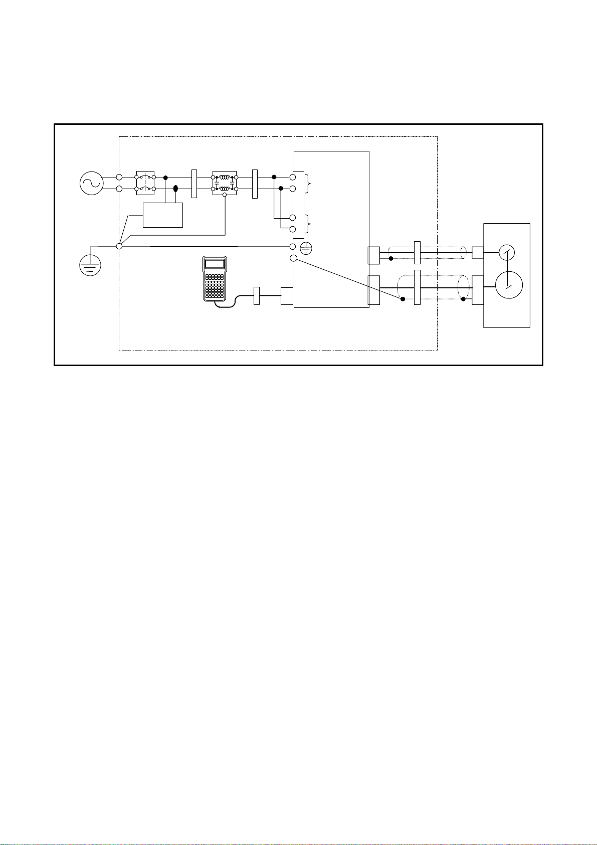
The wiring example shown below is one of our recommendations for the conformity with the EC Directives.
Figure 1: Wiring diagram (Example)
AC power
source
Protective
ground
Circuit
breaker
Surge
absorber
Noise
Ferrite
core 1
3 turns)
filter
Ferrite
core 2
2 turns
EDC Driver Unit
CN5
L
Control
N
power
L
Main
N
power
Ferrite
core 3
(1 turn)
PS Series
Megatorque Motor
Resolver
CN3
Ferrite core 3
(2 turns)
CN4
Ferrite
core 3
(1 turn)
Motor
Inside of
control
CN1
Handy
Terminal
panel
Environmental conditions
The Driver Unit must be used in the environmental condition of Pollution Degree1 or 2 as specified
by IEC60664-1. The Driver Unit shall be installed into a control panel with the structure that does not
allow penetration of water, oil or dust (IP54).
Power source
The EDC Driver Unit shall be used in the environmental condition of “Over-voltage category III” as
specified by IEC60664-1.
Circuit breaker
Install a circuit breaker that conforms to IEC standard and UL safety standard between the power
source and the Driver Unit.
Noise filter
Install a noise filter between the power source and the Driver Unit.
Ferrite core
Ferrite cores for signal cable shall be set to the power cable, the Motor cable and the resolver cable.
Protective Grounding
Be sure to ground the protective grounding terminal of the EDC Driver Unit to the protective ground
(PE) of the control panel for a measure against electrical shock.
Page 9

Table 2: List of recommended part
Item Specification Manufacturer Remarks
Circuit breaker Rated current: 15 [A]
Noise filter
Surge absorber –
Ferrite core 1 -
Ferrite core 2 -
Ferrite core 3 –
Single phase:
250 [VAC], 10 [A]
Single phase: EA32AC-15
(Fuji Electric)
FN2070-10/07
(SCHAFFNER)
R-A-V781BWZ-4
(Okaya electric)
E04RA400270150
(Seiwa Electric MFG)
E04SR301334
(Seiwa Electric MFG)
E04SR211132
(Seiwa Electric MFG)
Conforms to IEC regulations
and approved by UL
For the Terminal
Conformity with Underwriters Laboratories Standards
The Megatorque Motor and the EDC Driver Unit are qualified products for the following UL Standard for
safety.
Table 3
Subject Qualified regulation File No.
Megatorque Motor
Driver Unit
UL1004-1 E216970
UL508C E216221
Conditions to Meet UL Standards
Be sure to meet the following as they are the supplementary conditions for the qualification.
Environmental conditions
The Driver Unit must be used in the environmental condition of Pollution Degree1 or 2 as specified
by IEC60664-1. The Driver Unit shall be installed into a control panel with the structure that does not
allow penetration of water, oil or dust (IP54).
Power source
・ The EDC Driver Unit shall be used in environmental condition of “Over-voltage category III” as
specified by IEC60664-1.
・ Suitable for use on a circuit capable or delivering not more than 5,000 rms symmetrical amperes,
240 [V] maximum.
Circuit breaker
Install a circuit breaker (rated 15[A]) that conforms the UL safety standard between the power source
and the Driver Unit. (Please refer to Table 2 above for the specifications.)
Protective Grounding
Be sure to ground the protective grounding terminal of the EDC Driver Unit to the protective ground
(PE) of the control panel for a measure against electrical shock.
Wiring
・ Use 60/75 [°C] CU wire only (For models except for M-EDC-PN3 and M-EDC-PN4 Series),
Use 75 [°C] CU wire only (For models M-EDC-PN3 and M-EDC-PN4 Series).
Page 10

・ Wire range for field wiring terminals are marked adjacent to the terminal, on the wiring diagram
or instruction manual.
Table 4: Acceptable lead diameter
Model No.
All Models 18 19
Wire Range(AWG)
Input Output
Others
・ Solid state motor overload protection level of 115 [%] of FLA is provided in each model.
・ Integral solid state short circuit protection does not provide branch circuit protection. Branch
circuit protection must be provided in accordance with the National Electrical Code and any
additional local codes.
!
Caution : - Risk of Electric Shock- Capacitor discharge time is at least 5 [min]
Page 11

Contents
1. Introduction------------------------------------1-1
1.1. Notes for Users--------------------------------------------1-2
1.1.1. Notes for Safety -----------------------------------1-2
1.1.2. Precautions for Use -------------------------------1-2
1.1.3. Interchangeability of Motor and Driver Unit
-----------------------------------------------------1-5
1.2. Terminology ------------------------------------------------1-6
2. Specifications ---------------------------------2-1
2.1. System configuration-------------------------------------2-1
2.1.1. Control Mode----------------------------------------2-1
2.1.2. Examples of System Configuration------------2-2
2.2. Referebce Number and Coding -----------------------2-4
2.2.1. PS Series Megatorque Motor-------------------2-4
2.2.2. EDC Driver Unit for
PS Series Megarotque Motor----------------2-4
2.2.3. Cable Set --------------------------------------------2-4
2.2.4. Handy Ternminal-----------------------------------2-4
2.3. Name of Part-----------------------------------------------2-5
2.3.1. PS Series Megatorque Motor-------------------2-5
2.3.2. EDC Driver Unit ------------------------------------2-6
2.3.3. Handy Terminal ------------------------------------2-8
2.4. Standard Combiantion of Motor and Driver Unit
-----------------------------------------------------------------2-9
2.4.1. Motor and EDC Driver Unit Combinations ---2-9
2.4.2. Cable Set ------------------------------------------ 2-10
2.4.3. Handy Teminal ----------------------------------- 2-10
2.5. Motor Specifications------------------------------------2-11
2.5.1. PS Series Megatorque Motor----------------- 2-11
2.5.2. Axial Load and Moment Load-----------------2-12
2.6. External Dimensions -----------------------------------2-13
2.6.1. PS Series Megatorque Motor----------------- 2-13
2.6.2. EDC Driver Unit ----------------------------------2-14
2.6.3. Cable Set ------------------------------------------ 2-16
2.3.6.1 Fixed Use Cable---------------------------2-16
2.3.6.2 Flexible Cable------------------------------ 2-16
2.7. Driver Unit Specifications -----------------------------2-19
2.8. RS-232C Interface Specifications------------------- 2-19
2.8.1. CN1: RS-232C Serial Communication
Connector-----------------------------------2-19
2.8.1.1. CN1 Pin^Out------------------------------- 2-19
2.8.1.2. CN1 Signal List---------------------------- 2-19
2.9. Specifications of Control Input/OutputInter facing
--------------------------------------------------------------- 2-20
2.9.1. CN2: Control Input/Output Signsl Connector
------------------------------------------------------------- 2-20
2.9.1.1. CN2 Pin-Out -------------------------------2-21
2.9.1.2. CN2 Signal List---------------------------- 2-22
2.9.2. CN2 Interfacing----------------------------------- 2-25
2.9.2.1. General Input Signal---------------------2-25
2.9.2.2. Pulse Train Input Signal ----------------2-26
2.9.2.3. Output Signal------------------------------ 2-27
2.9.2.4. Position Feedback Signal Output
-----------------------------------------------2-27
2.9.2 5, Analog Monitor Output-------------------2-28
2.10. CN3: Resolver Cable Connector --------------------2-29
2.10.1. CN3 Pin-Out-------------------------------------2-29
2.10.2. CN3 Signal List ---------------------------------2-29
2.11. CN4: Motor Connector -------------------------------2-30
2.11.1. CN4 Pin-Out-------------------------------------2-30
2.11.2. CN4 Signal List ---------------------------------2-30
2.12. CN5: Connector for Power Supply ----------------2-31
2.12.1. CN5 Pin-Out-------------------------------------2-31
2.12.2. CN5 Wiring Diagram---------------------------2-31
3. Unpacking, Installation and Wiring ------3-1
3.1. Unpacking-------------------------------------------------- 3-1
3.1.1. Receiving Check ---------------------------------- 3-1
3.1.2. Motor and EDC Driver Unit Combinations-- 3-1
3.2. Installation-------------------------------------------------- 3-2
3.2.1. Motor Mounting------------------------------------ 3-2
3.2.1.1. Environmental Conditions of Motor
------------------------------------------------ 3-2
3.2.1.2. Motor Installation--------------------------- 3-2
3.2.1.3. Coupling Load to Motor ------------------ 3-3
3.2.1.4. Confirmation of Use Conditions-------- 3-3
3.2.1.5. Dummy Inertia------------------------------ 3-3
3.2.2. Installation of Driver Unit------------------------ 3-4
3.3. Wiring ------------------------------------------------------- 3-5
3.3.1. Cable Set-------------------------------------------- 3-5
3.3.2. Connecting Power -------------------------------- 3-6
3.3.3. Ground Connection------------------------------- 3-7
3.3.4. Connector Wiring---------------------------------- 3-8
3.3.4.1. Wiring Example (CN2)-------------------- 3-9
3.4. Power on --------------------------------------------------3-10
3.4.1. Precautions Before Power on-----------------3-10
3.4.2. Points to Be Checked when Power on -----3-11
3.4.3. Polarity Setting
(Normally Open Contact and Normally Closed
Contact)--------------------------------------------3-12
3.4.4. Power on and Servo on ------------------------3-13
4. Handy Terminal communication----------4-1
4.1. Cehck on Handy Terminal ----------------------------- 4-2
4.2. Parameter Setting---------------------------------------- 4-2
4.2.1. Input of the Password---------------------------- 4-2
4.2.2. Reset to Shippong Set--------------------------- 4-3
4.3. Monitoring Parameter ----------------------------------- 4-3
4.3.1. Monitoring Parameters by a Group ----------- 4-4
4.3.2. Monitoring Parameters Altered
from Shipping Set ------------------------------- 4-4
4.4. Monitoring Current Status------------------------------ 4-5
4.4.1.Inputting a Command while Monitoring Multiple
Conditions ------------------------------------------4.5
— i —
Page 12

5. Tuning ------------------------------------------5-1
5.1. Tuning Flowchart------------------------------------------5-1
5.2. Tuning Level 1: Automatic Tuning--------------------5-2
5.2.1. Precaustions for Automatic Tuning------------5-3
5.2.2. initilization of Servo Parameters ---------------5-4
5.2.3. Automatic Tuning ----------------------------------5-5
5.2.4. Trial Running----------------------------------------5-7
5.3. Tuning Level 2: Servo Gain Tuning ------------------5-9
5.3.1. Input of Load Inertia-------------------------------5-9
5.3.1.1. When Load Inertia Is Unknown ---------5-9
5.3.2. Minor Tuning of Servo Gains ----------------- 5-10
5.4. Tuning Level 3: Manual Tuning---------------------- 5-13
5.4.1. Precautions for Manual Tuning--------------- 5-13
5.4.2. Setting Velocity Loop
Proportional Gain (VG) ------------------------ 5-13
5.5. Setting Filters (Tuning Level 2)---------------------- 5-15
5.5.1. Setting Low-pass Filter-------------------------5-15
5.5.2. Setting Notch Filter------------------------------5-16
6. Operation---------------------------------------6-1
6.1. Preparation -------------------------------------------------6-1
6.1.1. Wiring Check----------------------------------------6-1
6.1.2. Operation Procedure------------------------------6-1
6.2. Position Scale----------------------------------------------6-2
6.2.1. Resolution of Position Scale --------------------6-2
6.2.2. Position of Position Scale------------------------6-3
6.2.3. Setting of Home Position-------------------------6-4
6.2.4. Software Over Travel Limit----------------------6-6
6.2.4.1. Setting Limits by Teaching ---------------6-7
6.2.4.2. Setting Limits by Direct Input------------6-8
6.3. Positioning Operation-----------------------------------------6-9
6.3.1. Positioning Command ----------------------------6-9
6.3.2. Program Positioning Operation---------------6-10
6.3.2.1. Program Positioning Operation via
Control Inputs and Outputs ----------- 6-12
6.3.2.2. Program Positioning Operation
via RS-232C Communication --------6-14
6.3.2.3. Programming ------------------------------6-15
6.3.2.4. Program Sequence ----------------------6-20
6.3.3. Pulse Train Command Positioning Operation --
-------------------------------------------------------6-23
6.3.3.1. Format of Pulse Train Input------------6-26
6.3.3.2. Resolution of Pulse Train--------------- 6-27
6.3.3.3. Input Timing--------------------------------6-28
6.3.4. Jogging--------------------------------------------- 6-29
6.3.4.1. Jogging with Control Input and Output
------------------------------------------------6-30
6.3.4.2. Jogging via RS-232C Communication
------------------------------------------------6-31
6.3.5. RS-232C Communication Positioning
Operation ------------------------------------------ 6-32
7. General Function-----------------------------7-1
7.1. Control Input----------------------------------------------- 7-1
7.1.1. Emergency Stop: EMST------------------------- 7-1
7.1.2. Alarm Clear: ACLR ------------------------------- 7-2
7.1.3. Hardware Over Travel Limit: OTP and OTM-----
--------------------------------------------------------- 7-3
7.1.4. Servo on: SVON----------------------------------- 7-4
7.1.5. Program Start: RUN
Internal Program Channel Selection: PRG0 to 7
7-6
7.1.6. Stop: STP------------------------------------------- 7-7
7.1.7. Jogging: JOG
Jog Direction: DIR-------------------------------- 7-9
7.2. Control Output -------------------------------------------7-10
7.2.1. Driver Unit Ready: DRDY----------------------7-10
7.2.2. Warning: WRN------------------------------------7-10
7.2.3. Over Travel Limit: OTPA and OTMA--------7-11
7.2.4. Servo State: SVST-------------------------------7-13
7.2.5. In Operation: BUSY -----------------------------7-14
7.2.6. In-position: IPOS---------------------------------7-15
7.2.6.1. CFIN Mode (Parameter FW < 0)------7-16
7.2.6.2. IPOS Mode (Parameter FW = 0)------7-17
7.2.6.3. FIN Mode (Parameter FW > 0)--------7-18
7.2.6.4. Parameter IN: In-position Limit--------7-19
7.2.6.5. In-position Stability Timer:
Parameter IS------------------------------7-19
7.2.7. Target Proximity: NEARA and NEARB -------7-20
7.2.8. Position Feedback Signal----------------------7-21
7.2.8.1. Resolution of Position Feedback Signal
-------------------------------------------------7-22
7.2.8.2. Signal Output Timing---------------------7-24
7.3. RS-232C Monitor----------------------------------------7-25
7.3.1. Monitoring Way for Control Input/Output Signal
--------------------------------------------------------7-26
7.3.1.1. Electric Condition Monitor: Monitor IO0
-------------------------------------------------7-27
7.3.1.2. Monitor for Internal Recognition of Input
and Output State: Monitor IO1 --------7-28
7.3.1.3. Monitor for State of Input Functions:
Monitor IO2---------------------------------7-28
7.3.1.4. Monitor for State of Output Functions:
Monitor: IO3--------------------------------7-29
7.3.1.5. Monitor for Individual Function --------7-29
7.3.2. Alarm Monitor-------------------------------------7-30
7.3.2.1. Monitor for All Occurring Alarmas
at Once--------------------------------------7-30
7.3.2.2. Monitor for Alarm History and Event:
Monitor TA?HI----------------------------7-31
7.3.3. Pulse Train Counter: Monitor RP ------------7-32
7.3.4. Position Feedback Signal Counter:
Monitor FK-----------------------------------------7-32
7.3.5. Current Position Monitor: Monitor TP-------7-32
7.3.6. Software Thermal Loading Monitor: Monitor TJ
--------------------------------------------------------------7-33
— ii —
Page 13

7.4. Analog Monitor-------------------------------------------7-34
7.4.1. Use of Preset Monitor---------------------------7-35
7.4.2. Customization of Monitor Data ---------------7-36
7.4.2.1. Analog Monitor for State of Control Inputs
and Outputs Functions ----------------- 7-37
8. More Advanced Function ------------------8-1
8.1. Assignment of Input/Ouput Function-----------------8-1
8.1.1. Function of Input -----------------------------------8-2
8.1.2. Funciton of Control Outpurt ---------------------8-4
8.1.3. Edit of function of Control Input and Output
---------------------------------------------------------8-6
8.1.3.1. Edit of Control Input Function -----------8-6
8.1.3.2. Edit of Control Ouput Function----------8-8
8.1.3.3. Masking of Control Output Function
------------------------------------------------8-10
8.1.3.4. Forcible Change in Setting of Output
Port Function -----------------------------8-11
8.2. Extended Control Input-------------------------------- 8-12
8.2.1. Input HOLD: HLD--------------------------------8-12
8.2.2. Velocity Override: ORD ------------------------ 8-13
8.2.3. Integration OFF: IOFF--------------------------8-14
8.2.4. Home Return Start: HOS ---------------------- 8-15
8.2.5. Home Position Limit: HLS --------------------- 8-15
8.3. Extended Control Output ------------------------------ 8-16
8.3.1. In-zone Output: ZONEA, ZONEB,
and ZONEC ------------------------------------- 8-16
8.3.2. Outputs of Operating Conditions ----------- 8-17
8.3.2.1. Position Error: TEU (Position Error,
Under) and TEO (Position Error, Over)
------------------------------------------------8-18
8.3.2.2. Velocity: Outputs TVU (Velocity, Under)
and TVO (Velocity, Over)-------------- 8-19
8.3.2.3. Torque Command: Outputs TTU (Torque
Command, Under) and TTO (Torque
Command, Over)-------------------------- 8-19
8.3.2.4. Thermal Loading: Outputs TJU (Thermal
Loading, Under) and TJO (Thermal
Loading, Over)-----------------------------8-20
8.3.3. Travel Limit Output (±): OTXA---------------- 8-21
8.3.4. Output Normal: NRM----------------------------8-22
8.3.5. Home Return Completed: HOME ------------ 8-22
8.3.6. Home Position Defined: HCMP -------------- 8-22
8.4. Teaching -------------------------------------------------- 8-23
8.4.1. Preparation for Teaching-----------------------8-24
8.4.2. Teaching of Parameter------------------------- 8-24
8.4.3. Teaching the Position Data of Positioning
Program ------------------------------------------- 8-25
8.5. 8.5. Tuning------------------------------------------------8-26
8.5.1. Servo Block Diagram --------------------------- 8-26
8.5.2. Digital Filter---------------------------------------- 8-28
8.5.3. Position Loop Dead Band----------------------8-29
8.5.4. Automatic Gain Switching --------------------- 8-30
8.6. Positioning Operation ----------------------------------8-31
8.6.1. Acceleration Profiling and Individual
Acceleration Setting------------------------------8-31
8.6.2. Examples of Acceleration Profiling and
Individual Setting of Acceleration and
Deceleration --------------------------------------8-33
8.6.3. Shorter Way Positioning------------------------8-34
8.6.4. User Scale Positioning--------------------------8-36
8.7. Program Operation -------------------------------------8-39
8.7.1. Change of Parameter via Program Operation
--------------------------------------------------------8-39
8.7.2. Automatic Program Execution at Power on
--------------------------------------------------------8-41
8.8. Home Return ---------------------------------------------8-45
8.8.1. Home Return Operation via the Home Position
Sensor----------------------------------------------8-47
8.8.1.1. Home Return Mode: OS4---------------8-47
8.8.1.2. Home Return Mode: OS5---------------8-49
8.8.1.3. Home Return Mode: OS1---------------8-49
8.8.1.4. Home Return Mode: OS3---------------8-49
8.8.2. Home Return with Travel Limit ---------------8-50
8.8.2.1. Home Return Mode: OS7---------------8-50
8.8.3. Teaching of Home Position--------------------8-51
8.8.3.1. Home Return Mode: OS6---------------8-52
8.8.3.2. Teaching of Home Position in
Servo-off Sate------------------------------8-53
8.8.4. Position Adjustment of Home Limit Sensor
--------------------------------------------------------8-54
8.8.5. Teaching of Home Position Offset-----------8-55
8.9. RS-232C Communication-----------------------------8-56
8.9.1. Specifications of Communication ------------8-56
8.9.2. Communication Procedure --------------------8-56
8.9.2.1. Power on------------------------------------8-56
8.9.2.2. Command Entry---------------------------8-57
8.9.2.3. Cancelling Command--------------------8-58
8.9.2.4. Input of the Password--------------------8-58
8.9.2.5. Readout of Parameter Settings and
Internal State-------------------------------8-59
8.9.2.6. Reading out Parameter Settings by a
Group-----------------------------------------8-60
8.9.2.7. Error Message-----------------------------8-61
8.9.3. Communication with Personal Compute ---8-62
8.9.3.1. Setup of Hyper Terminal----------------8-62
8.9.3.2. Backup of Parameter --------------------8-63
8.9.3.3. Restoring Parameters -------------------8-64
— iii —
Page 14

9. Details of Command and Parameter----9-1
9.1. Handling Instruction of Command and Parameter
-----------------------------------------------------------------9-1
9.1.1. Character String of Command------------------9-1
9.1.2. Grammar of Command -------------------------9-1
9.1.3. Error Message--------------------------------------9-2
9.1.4. Multi-statement on a Line------------------------9-2
9.1.5. Wildcard Search------------------------------------9-3
9.1.6. Repeating Readout--------------------------------9-3
9.1.7. Multi-monitor ----------------------------------------9-4
9.1.8. Initialization of Specified Parameter-----------9-4
9.1.9. Adjusting ---------------------------------------------9-5
9.1.10. Output to Analog Monitor-----------------------9-5
9.2. Glossary of Command and Parameter --------------9-6
9.3. Parameter List -------------------------------------------9-85
10. Maintenance-------------------------------10-1
10.1. Backup Parts -------------------------------------------10-1
10.2. Storing the Parts---------------------------------------10-1
10.3. Periodic Check----------------------------------------- 10-2
10.3.1. Motor ----------------------------------------------10-2
10.3.2. Driver Unit
(Including Cables and Handy Terminal)
-------------------------------------------------------10-2
10.4. Periodic Replacement of Parts---------------------10-3
10.4.1. Motor ----------------------------------------------10-3
10.4.2. Cables---------------------------------------------10-3
10.4.3. Driver Unit ---------------------------------------- 10-4
10.5. Repair Service ----------------------------------------- 10-6
10.6. Warranty Period and Covering Range----------- 10-6
10.6.1. Warranty Period -------------------------------- 10-6
10.6.2. Limited Warranty ------------------------------- 10-6
10.6.3. Immunities --------------------------------------- 10-6
10.6.4. Service Fee-------------------------------------- 10-6
10.6.5. Notice for discontinuity of the Product and
Duration of Support --------------------------- 10-6
11.3.6. Alarm A4: Excess Velocity -----------------11-11
11.3.7. Warning A5: Home Position Undefined-11-11
11.3.8. Alarm A7: Resolver Amplifier Alarm -----11-12
11.3.9. Alarm A9: Commutation Error-------------11-12
11.3.10. Warning C0: Position Command/Feedback
Signal Error ----------------11-13
11.3.11. Alarm C3: CPU Error-----------------------11-13
11.3.12. Alarm E0: RAM Error ---------------------- 11-14
11.3.13. Alarm E2: ROM Error----------------------11-14
11.3.14. Alarm E7: System Error-------------------11-15
11.3.15. Alarm E8: Interface Error ----------------- 11-15
11.3.16. Alarm E9: ADC Error-----------------------11-15
11.3.17. Warning F1: Excess Position Error ----- 11-16
11.3.18. Over Travel F2: Software Over Travel Limit -
------------------------------------------------------11-17
11.3.19. Over Travel F3: hardware Over Travel Limit-
------------------------------------------------------11-18
11.3.20. Alarm F4: Emergency Stop---------------11-19
11.3.21. Warning F5: Program Error -------------- 11-19
11.3.22. Warning F8: Automatic Tuning Error---11-20
11.3.23. Warning P0: Over Heat--------------------11-21
11.3.24. Alarm P1: Main Power Overvoltage----11-21
11.3.25. Alarm P2: Motor Over Current-----------11-22
11.3.26. Alarm P3: Control Power Under Voltage
------------------------------------------------------11-22
11.3.27. Warning P5: Main Power Under Voltage
------------------------------------------------------11-23
11.3.28. Alarm P9: Power Module Alarm---------11-23
12. Troubleshooting --------------------------12-1
12.1. Identifying Problem------------------------------------12-1
12.2. Troubleshooting----------------------------------------12-1
12.2.1. Power Trouble-----------------------------------12-2
12.2.2. Motor Trouble------------------------------------12-2
12.2.3. Vibration, Abnormal Noise or Unstable Settling
--------------------------------------------------------12-3
12.2.4. Improper Positioning---------------------------12-3
12.2.5. Communication Problem ---------------------12-4
11. Alarm and Warning ---------------------- 11-1
11.1. Identifying Alarm and Warning--------------------- 11-1
11.1.1. LED Alarm Indicator---------------------------11-1
11.1.2. Confirmation of Alarm and Warning------- 11-2
11.1.3. History of Alarm and Warning---------------11-3
11.2. List of Alarm and warning ---------------------------11-5
11.2.1. Normal State ------------------------------------11-5
11.2.2. Condition in the State of Alarm and Warning -
-------------------------------------------------------11-6
11.2.2.1. Alarm---------------------------------------11-6
11.2.2.2. Warning -----------------------------------11-7
11.2.2.3. Over Travel Limit------------------------ 11-7
11.3. Cause and Remedy-----------------------------------11-8
11.3.1. CPU Error----------------------------------------11-8
11.3.2. Alarm A0: Disconnected Sensor Cable---11-8
11.3.3. Alarm A1: Position Data Error---------------11-9
11.3.4. Alarm A2: Motor Cable Disconnected-----11-9
11.3.5. Warning A3: Software Thermal----------- 11-10
Appendix
— iv —
Appendix 1: How to Monitor Input and Output Signal-A-1
Appendix 2: How to Check Motor Condition-------------A-5
Appendix 3: How to Back up and Restore the Settings of
Programs and Parameters ------------------A-8
Appendix 3.1. When Using the Handy Terminal
FHT21-------------------------------------A-8
Appendix 3.2. When Using a Personal Computer
------------------------------------------------ A-11
Appendix 3.3. Back up Manually -------------------- A-14
Appendix 4: Procedure for Replacing EDC Driver Unit
-------------------------------------------------------------- A-16
Appendix 5: Dump Resistor-------------------------------- A-18
Appendix 6: Wiring of RS-232C Communication Cable ---
-------------------------------------------------------------- A-20
Appendix 7: Setting List of Parameter and Program of
EDC Driver Unit ------------------------------ A-21
Page 15

1. Introduction
This is the operation manual of the Megatorque Motor System with EDC Driver Unit. Please
refer to “2.4. Standard Combination List” for the applicable Megatorque Motor System.
Before operating the Megatorque Motor System for the first time, this manual should be read
thoroughly.
We describe the standard PS series Motors only in “2.5. Motor Specifications.” If your Motor is
not one of these, please refer to the attached specification document.
1.1. Notes to Users
1.1.1. Notes for Safety
For your safety, you should read this manual thoroughly and understand the contents before
operating the Megatorque Motor System.
The following notices are added to give particular emphasis on the safety precautions in this
manual.
!
Danger : A matter that might cause serious injuries.
!
Warning : A matter that might result in injuries.
!
Caution : A matter that might result in the breakdown of equipment into which the
1.1.2. Precautions for Use
Pay special attention to the following when installing, checking and troubleshooting the
Megatorque Motor System.
!
Caution : When making a combination of a Motor and a Driver Unit, confirm that
!
Caution : Do not cut the Cable Set, or do not hook it up to other cable.
Motor is installed or the break down of the mechanism surrounding the
Motor.
their specifications for Motor size and maximum Motor torque match
each other.
• This is because the Driver Unit holds the unique parameter settings for a
matching Motor.
• Refer to “2.4.Standard Combination List” for the combination.
• Make sure that the reference numbers on each identification plate of a Motor
and a Driver Unit indicate the same coding for Motor size, Motor maximum
torque and position sensor.
• If the reference numbers are not matched, the Motor may lose its accuracy and
emit noise, and furthermore, it may not move or lose its control.
• The modification of the Cable Set may worsen the Motor and Driver Unit
performances, typically positioning accuracy and repeatability of the resolver.
!
Caution : Never disassemble the Motor because it has been precisely assembled
and tuned.
• If disassembled, it may cause abnormalities such as deterioration in rigidity
and positioning accuracy, and generation of noise.
— 1-1 —
Page 16
!
Danger : Be sure to connect the Emergency Stop signal circuit to the EMST port
of the CN2 control I/O connector.
• Please set the System so that you can immediately stop the Motor in case of an
emergency.
!
Caution : Do not remove the panel of the Driver Unit so as not to cause an
electric shock. It is extremely dangerous due to high voltage present.
• Driver Units have high capacity electrolytic capacitors in its internal circuits,
and thus resulting in high residual voltage of the capacitors for few minutes
after the main power is turned off.
!
Danger : Do not place other objects in the path of the Motor when the Motor
power is on. An unexpected motion of the Motor may result in injury
and/or damage to the System or other mechanism.
!
Danger : Always stay in a safe place away from the operating area of the Motor
when the System is powered on.
!
Danger : If the Motor is fitted with an arm or similar devices, take extra care to
assure that no obstacles are in or around the Motor work area.
!
Caution : Use of an optional dump resistor shall be considered for a heavy-duty
operation.
• The Megatorque Motors regenerate when they decelerate carrying heavy load
inertia.
• An internal capacitor charges the Motor regeneration. However, when high
and continuous regeneration exceeding its capacity is applied, excess energy
activates an alarm “Alarm P1: Abnormal main power voltage” and the Motor
stops.
• In such a case, you need to decrease velocity, deceleration rate, and operation
duty cycle, or you require an external high capacity dump resistor.
!
Danger: Never apply water or oil to the Driver Unit.
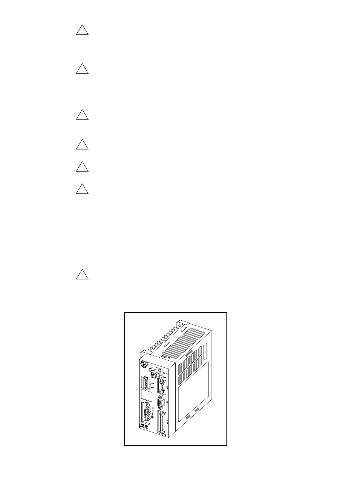
• Take appropriate measures to protect the Driver Unit from water, oil, slag,
dust, and corrosive gas.
Figure 1-2: EDC Driver Unit
— 1-2 —
Page 17

!
Warning : Do not test the insulation of the Driver Unit.
• The high voltage used in the test may destroy the internal circuits of Driver
Unit.
!
Caution : In most cases, the Direct Drive Motor System cannot exhibit its full
performance unless the shipping set of the parameters is altered for
actual applications.
• Refer to “5. Tuning” and be sure to set the servo parameters to actual use
conditions.
!
Caution : Allowable moment load and axial load depend on Motor size. Please
confirm that actual load conditions are in the limits of the Motor.
• Refer to “2.5. Motor Specifications” for the allowable moment load, axial load
and radial load.
!
Caution : An excessive eccentric load or an excessive load may cause the
permanent deformation of the rotor or premature failure of the bearing
inside the Motor. When handling the Motor, please pay special
attention not to drop it and not to give a shock to it. Protect the Motor
from a collision with an obstacle.
• Excessive load to the Motor may damage the bearing of Motor and may
mechanically lock the Motor.
• The flatness of the Motor mounting surface shall be 0.02 mm or less.
!
Caution : For an oscillating operation less than 45 [°], turn the Motor 90 [°] or
more at least once a day.
!
Caution : Do not give a direct impact to the Motor with a hammer or the like. A
direct impact to the outside of the Motor or the load fixed to the Motor
may deteriorate accuracy of the built-in position sensor.
!
Caution : When attaching a rotary machine component to the Motor such as a
bearing or a ball screw, be sure to align both centers within 0.01 mm.
Excessive eccentric load or excessive load to the Motor may cause the
premature failure of Motor’s bearing.
Warning:Be sure not to activate the dynamic brake in the following conditions.
!
Otherwise the dynamic brake circuit may break and the Motor will
enter in a “free run” state, leading to possible injuries.
◊ Do not activate the dynamic brake in normal operations. Stop the Motor by a control
command, not by the dynamic brake. The dynamic brake is an auxiliary function to
stop the Motor immediately in an emergency. In the middle of operation, an alarm, a
warning or the “Emergency stop” input activates the dynamic brake.
• Warnings that initiate “Servo-off” state are “A3” (Software thermal), “C0”
(Position command/Feedback error), “C5” (Field bass error), “F5” (Program
error), and “F8” (Automatic tuning error).
— 1-3 —
Page 18

◊ The load moment of inertia to a Motor must be 70 times or less than the Motor inertia
(100 times for the PS1, PS3 and PN2 type Motors). In case of an indexing operation, a
position command shall be 360 degrees or less, while the maximum speed for
continual rotation must be 0.5 [s
-1
] or less.
(However, there may be a possibility to exceed the above limits in some cases. Please
consult NSK when you require a close investigation on the limits.)
◊ For the PN4180 Motor, be sure to stop the Motor for 20 minutes or longer when you
stop it by the dynamic brake.
Caution: When the Motor is continually accelerating a high inertial load with high
!
acceleration, the system constantly outputs a high torque exceeding
the rated torque, and thus likely to activate the warning “A3” (Software
thermal). In such a case take a remedy to decrease the load moment
of inertia or to lower the speed.
— 1-4 —
Page 19

1.1.3. Interchangeability of Motor and Driver Unit
Interchangeable types
The standard Motors and the EDC Driver Units can be randomly matched (interchangeable).
You may have a combination of a Motor and a Driver Unit that have the different serial number.
However, please refer to “2.4. Standard Combination List” for combination of reference
numbers of the Motors, the Driver Units and the Cable Sets.
Non-interchangeable types
The interchangeability of the Motors and the Driver Units won’t be applicable for a Megatorque
Motor System that is made to a special order. In such a case please refer to respective
specification documents.
Be sure to make a combination of a Motor and a Driver Unit with the same serial number when
they are not interchangeable. Moreover, you must use the specified Cable Set.
Please be aware that the Megatorque Motor System won’t fully exhibit its performance as
described in its specifications if a Motor and a Driver Unit are matched with different serial
number, or if you change the length of the Cable Set. Especially in case of a System that
incorporates an absolute position sensor, you may lose positioning repeatability of the Home
position.
— 1-5 —
Page 20

1.2. Terminology
It is necessary to be familiar with some terms used in this document.
Cable Set
CCW
A cable set exclusive use for the Megatorque Motor System. Connects driver Unit and
Megatorque Motor
Counterclockwise; direction of Motor rotation. Seen from the top of rotor.
closed
count/rev.
Driver Unit
Handy Terminal
Motor
OFF (all capital)
ON (all capital)
open
servo-lock
servo-off
servo-on
shipping set
System
velocity gain (VG)
Logic output state; output current will flow.
Count/revolution. A unit of resolution. In some cases, it is described as pulse/rev. in this
manual.
Clockwise; direction of Motor rotation. Seen from the top of rotor.
CW
Means Megatorque Motor System’s driver unit when capitalized.
Means an optional handy terminal (M-FTH21) for RS-232C communication. Exclusive
use for Megatorque Motor System. .
A parameter to set a load inertia moment to the Motor. Unit is in [kg•m
LO
Means Megatorque Motor System’s motor when capitalized.
Logic input state; input will see an open circuit.
Logic input state; there will be a current path to the common DC supply.
Logic output state; no output current
One typical state of servo-on; the Motor provides torque and remains in position.
The state where the Driver Unit provides no current to the Motor, and the Motor provides
no torque. The Motor rotor can be rotated easily.
The state that the Driver Unit is ready to control the Motor, or is controlling the Motor.
A parameter setting or a Driver Unit function setting at shipping.
Means Megatorque Motor System when capitalized.
Shorter name for velocity loop proportional gain.
The velocity error, the deviation of velocity feedback from the velocity command, will be
amplified by a number defined as a velocity gain set by the parameter VG, and will be
output as a torque command.
2
].
The following commands are used for the Driver Unit to set function and to execute
operation.
Command:
Execution instruction to the Driver Unit. It includes the command RUN to start positioning
operation and stop commands to stop positioning operation.
Parameter:
The parameters hold the operational settings of internal function of the Driver Unit. Changing of
these settings enables to move the Motor as planed
◊ Global parameter:
A parameter set to a command line in program channels. This term is used to
distinguish them from local parameters. It is stored in a non-volatile memory.
◊ Local parameter:
A parameter that is temporarily becomes effective in a program operation. It is not
stored to a non-volatile memory.
Monitor
A monitor holds the internal state of the Driver Unit, such as Motor velocity and position scale
data. You can monitor them anytime.
— 1-6 —
Page 21

2. Specifications
2.1. System Configuration
2.1.1. Control Mode
The EDC Driver Unit is compatible with several interface devices.
Table 2-1: Applicable interface and control mode
Applicable
interface
General
Input/Output
Pulse train input
RS-232C
communication
CC-Link
<Program operation>
• Positioning commands are programmed
and stored to the Driver Unit.
• Performs a positioning by the inputs of
channel selection and the program starting
command.
• The commands are in the absolute or
incremental position format.
<Jogging operation>
• The Motor rotates to any point by the Jog
input and the Jog direction input.
<Home Return operation>
• Set a current position to the Home
position or set the Home position by
Home Return operation started by the
Home position limit input.
• An input of starting Home Return signal
executes the operation.
<Pulse train command positioning
operation>
• Number of input pulses governs the
positioning operation.
<RS-232C serial communication>
• The master controller outputs directly the
positioning command.
<Program operation>
• Program start command starts positioning
operation.
<Jogging operation>
• The Jog operation command moves the
Motor to any point.
<Home Return operation>
• Executes Home Return operation by the
start command of Home Return.
<Program operation>
• Positioning operation is controlled by the
input signals of channel selection and
program start in the CC-Link.
<Jogging operation>
• The Motor rotates to any point by the Jog
input and the Jog direction input in the
CC-Link.
<Home Return operation>
• Input of the start command of Home
Return operation in the CC-Link executes
the operation.
Control mode Controllers/Interfacing devices Application
• PLC (Input/Output unit)
• NC controller (Provided with
Inputs/Outputs of M function)
• PLC
(Positioning control unit)
• Position controller (Pulse output)
• PLC
(Serial communication unit)
• RS-232C communication terminal
(Personal computer, etc.)
• PLC compatible with CC-Link
• Various types
of indexing
application
• Intermittent
positioning
control
— 2-1 —
PLC: Programmable Logic Controller
Page 22
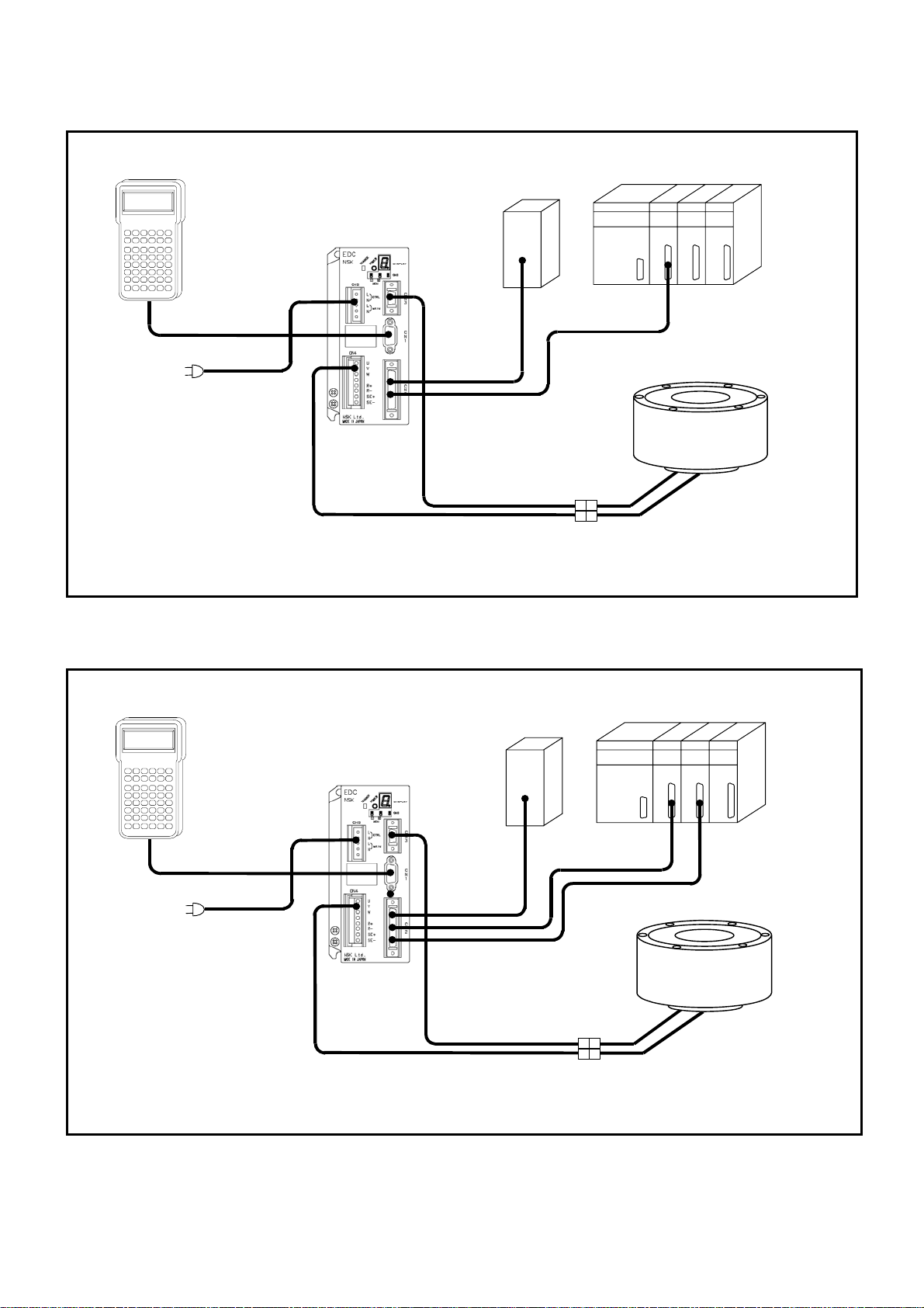
2.1.2. Examples of System Configuration
K
Fig 2-1: System configuration for program operation
Handy Terminal
NS
#
&
Single phase:
200 to 230 [VAC]
100 to 115 [VAC]
HANDY TERMINAL
>
3 <2 $1
- +5 %4
)
8 (7 ‘6
. =0 ?9
CBA FED
IHG LKJ
ONM RQP
UTS XWV
?ZY */,
CTRLESCSHIFT ENTSPBS
comm unication
Main power
or
RS-232C
EDC Driver Unit
24 VDC
power supply*
Contorl I/O signal
Control
power
Cable set
Resolver cable
Motor cable
PLC*
Motor controller*
PS series Megatorque Motor
* User shall provide these devices.
Fig 2-2: System configuration for pulse train command positioning
Hand y Terminal
NSK
HANDY TERMINA L
#
3 <2 $1
&
8 (7 ‘6
CBA FED
IHG LKJ
ONM RQP
UTS XWV
?ZY */,
CTRLESCSHIFT ENTSPBS
Single phase:
200 to 230 [VAC]
100 to 115 [VAC]
>
- +5 %4
)
. =0 ?9
RS-232C
communication
Main power
or
EDC Driver Unit
24 VDC power supply*
Control I/O signal
Control
power
Pulse train input
Cable set
Resolver cable
Motor cable
PLC*
Motor controller*
PS series Megatorque
Motor
* The user shall provide these devices.
— 2-2 —
Page 23
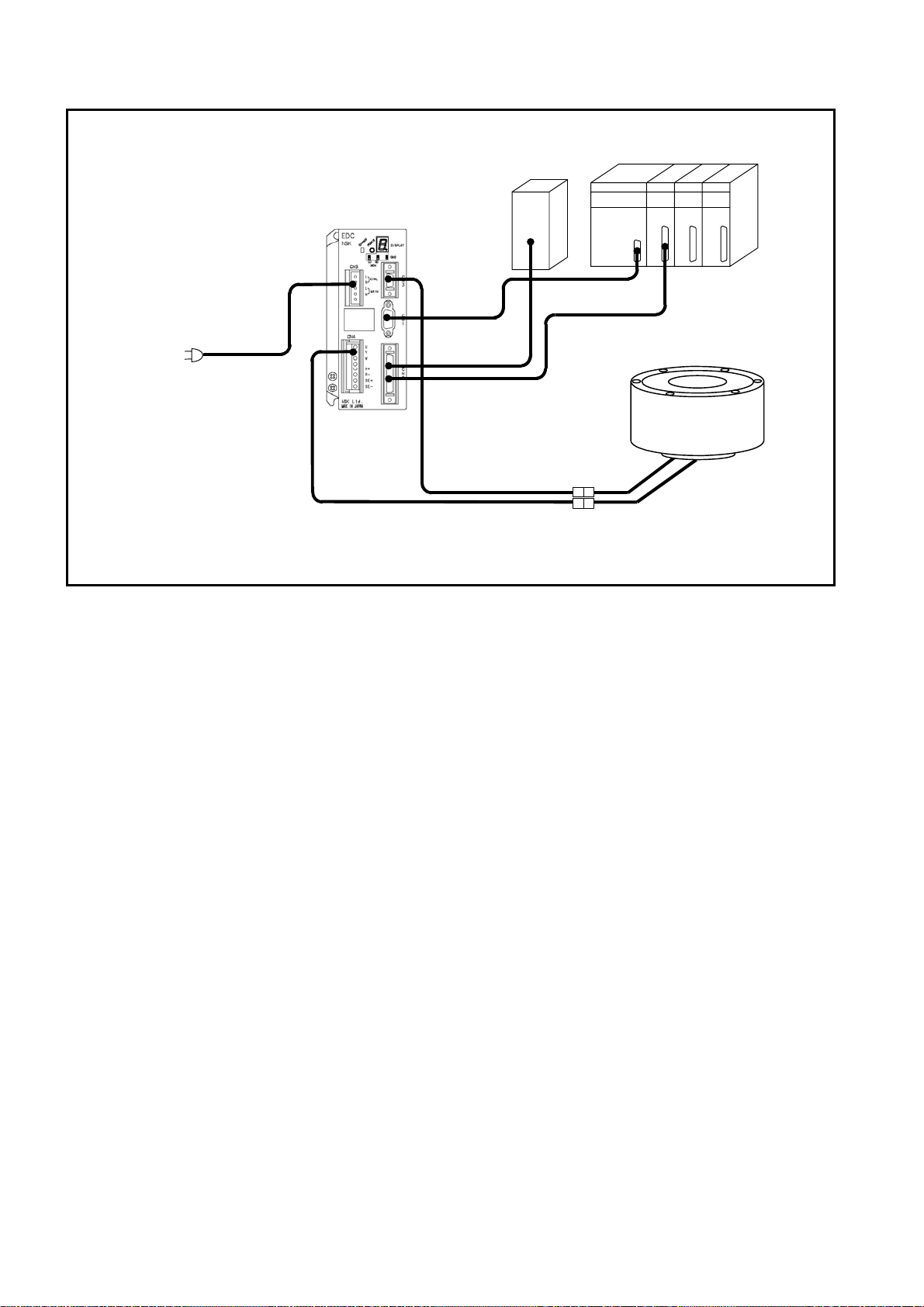
Fig 2-3: System configuration for RS-232C serial communication command positioning
24 VDC
power supply*
EDC Driver Unit
RS-232C
communication
Main power
Control power
Single phase :
200 to 230 [VAC]
or
100 to 115 [VAC]
Cable set
Resolver cable
Motor cable
Control I/O signal
PLC*
Motor contro l ler*
PS series Megatorque
Motor
* The user shall provide these devices
— 2-3 —
Page 24
2.2. Reference Number and Coding
2.2.1. PS Series Megatorque Motor
Fig 2-4 :Reference number coding of PS series Megatorque Motor
Megatorque Motor
PS series
Motor size code
Motor maximum torque [N•m]
M-PS 1 006 K N 002
2.2.2. EDC Driver Unit for PS Series Motor
Fig 2-5: Reference number coding of EDC Driver Unit for PS series Megatorque Motor
M-EDC –PS1006AB5 02–01
EDC Driver Unit
Motor model
Power voltage A: 200 to 230 [VAC] (single phase)
C: 100 to 115 [VAC] (single phase)
Position sensor code B: Absolute position sensor
Design number
002: Standard
003: High-precision products
N: No brake
K: Incorporates absolute posiiton
sensor
No code:Connectors,fixing blackets and manual
are not ncluded (PS/PN Series only)
01:Connectors,fixing blackets and Japanese
manual are included
02:Connectors,fixing blackets and Engllish
manual are included
Design serial number: 02: Standard.
03: High-precision produts
(Made to order)
Function: 5: Standard
C: CC-Link (Optional)
2.2.3. Cable Set
Fig 2-6: Reference number coding of Cable Set for PS series Megatorque Motor
※
Cable length has to be less than 8 [m] for combi nations with PN2012 or high-precision product s in PS series.
2.2.4. Handy Terminal
Fig 2-7: Reference number coding of Handy terminal
Handy Terminal
M-C 004 SCP 03
Cable Set for
Megaorque Motor
Example: 002… 2 m
004… 4 m
010…10 m
015…15 m
030…30 m
M-FHT 21
Design number
03: Stationary Cable
13: Flexible Cable
PS/PN Series and PN Series with brake
Handy Terminal serial number
— 2-4 —
Page 25
2.3. Name of Each Part
2.3.1. PS Series Megatorque Motor
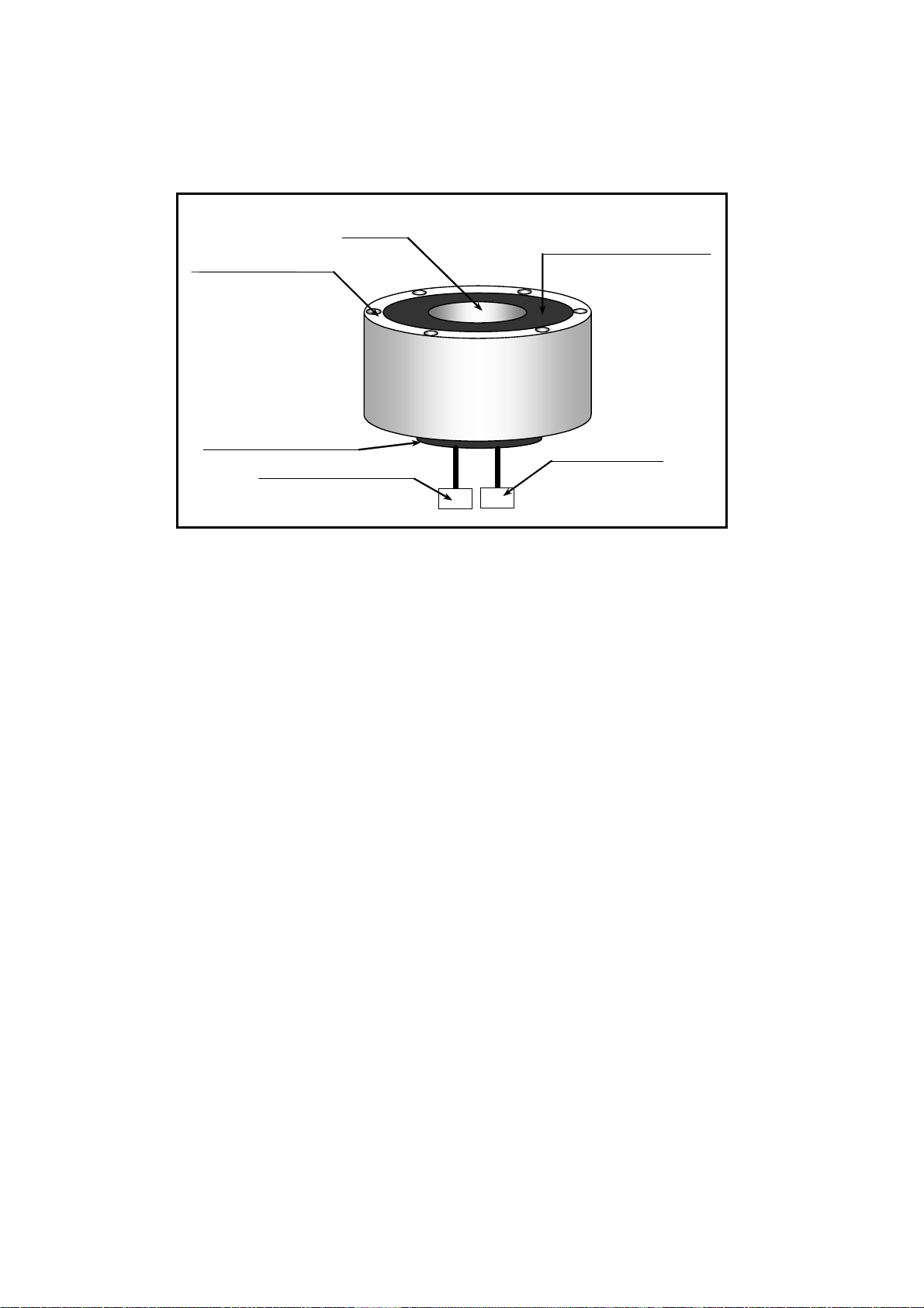
Fig 2-8: PS series Megatorque Motor
Rotor (rotational part)
Stator (stationary part)
Resolver connector
Hollow
Dust cover (stationary part)
Motor connector
— 2-5 —
Page 26
2.3.2. EDC Driver Unit
(1)
(7)
(9)
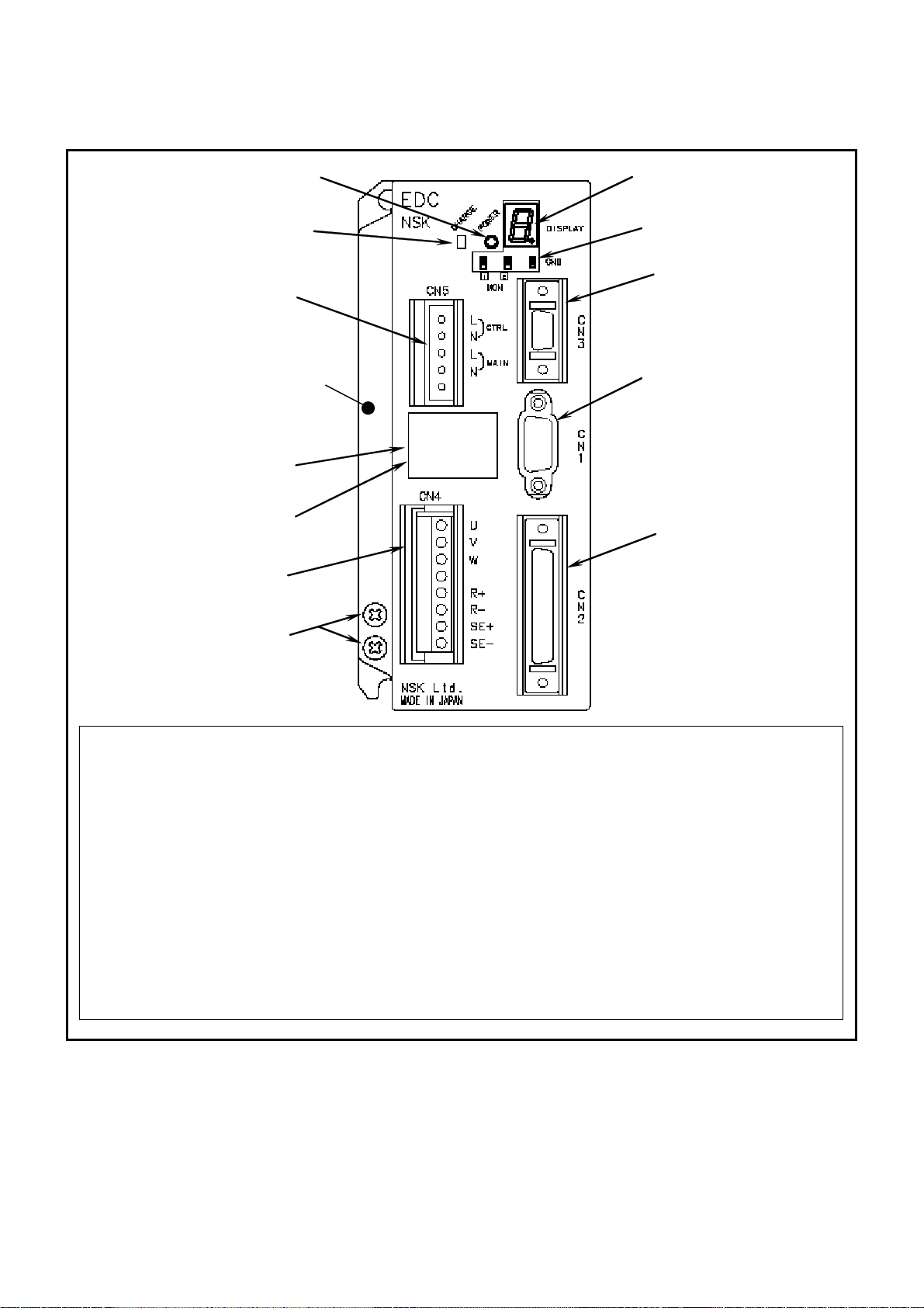
Fig 2-9: EDC Driver Unit (standard)
(12)
(11)
Heatsink
(8)
(6)
(2)
(10)
(5)
(3)
(4)
(1) Power LED
(2) 7 segments LED
(3) CN1 (9 pins)
RS-232C serial communication cable connector
Connect the optional Handy Terminal FHT21.
(4) CN2 (50 pins)
Motor control Input/Output signal (I/O) connector
(5) CN3 (14 pins)
Resolver cable connector
Connect the exclusive resolver cable.
(6) CN4
Motor cable connector
Connect the exclusive Motor cable.
(7) Ground terminal.
M4 screws
(8) Type
Reference number plate
(9) No.
Serial number plate
(10)Monitor terminal
(11)CN5
Connector for main power
(12)Power amplifier charge indicator
Indicates that the capacitor of the power
amplifier still charges residual voltage.
— 2-6 —
Page 27
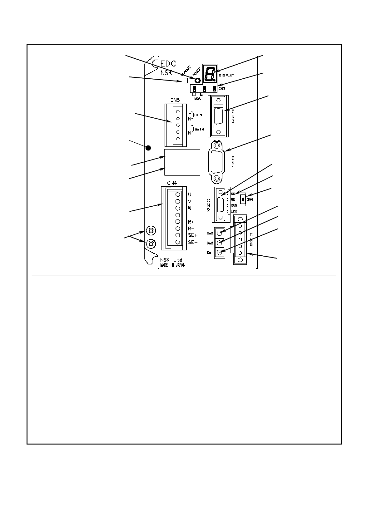
Fig 2-10: EDC Driver Unit compatible with CC-Link
(2)
(3) (4)
(7)
(6) (8) (9)
(10)
(18) (17)
(16) (15) (14)
(13)
(1)
(12)
(11)
Heatsink
(5)
7 segments LED
(2)
CN1 (9 pins)
(3)
RS-232C serial communication connector
Connect the optional Handy Terminal FHT21.
CN2 (10 pins)
(3)
Motor control Input/Output (I/O) signal connector
CN3 (14 pins)
(5)
Resolver cable connector
Connect the exclusive resolver cable.
CN4
(6)
Motor cable connector
Connect the exclusive Motor cable.
Ground terminal
(7)
M4 screw
Type
(8)
Reference number plate
Main power LED
(1)
(9) No.
Serial number plate
(10)Monitor pins
(11)CN5
Main power connector
(12)Power amplifier charge indicator
Indicates that the capacitor of the power
amplifier still charges residual voltage.
(13)CN6
CC-Link connector
(14)SW4
Switch for the terminating resistance
(15)SW1
Station number setting switch (×10)
(16)SW2
Station number setting switch (×1)
(17)SW3
Baud rate setting
(18)Monitor LED
— 2-7 —
Page 28
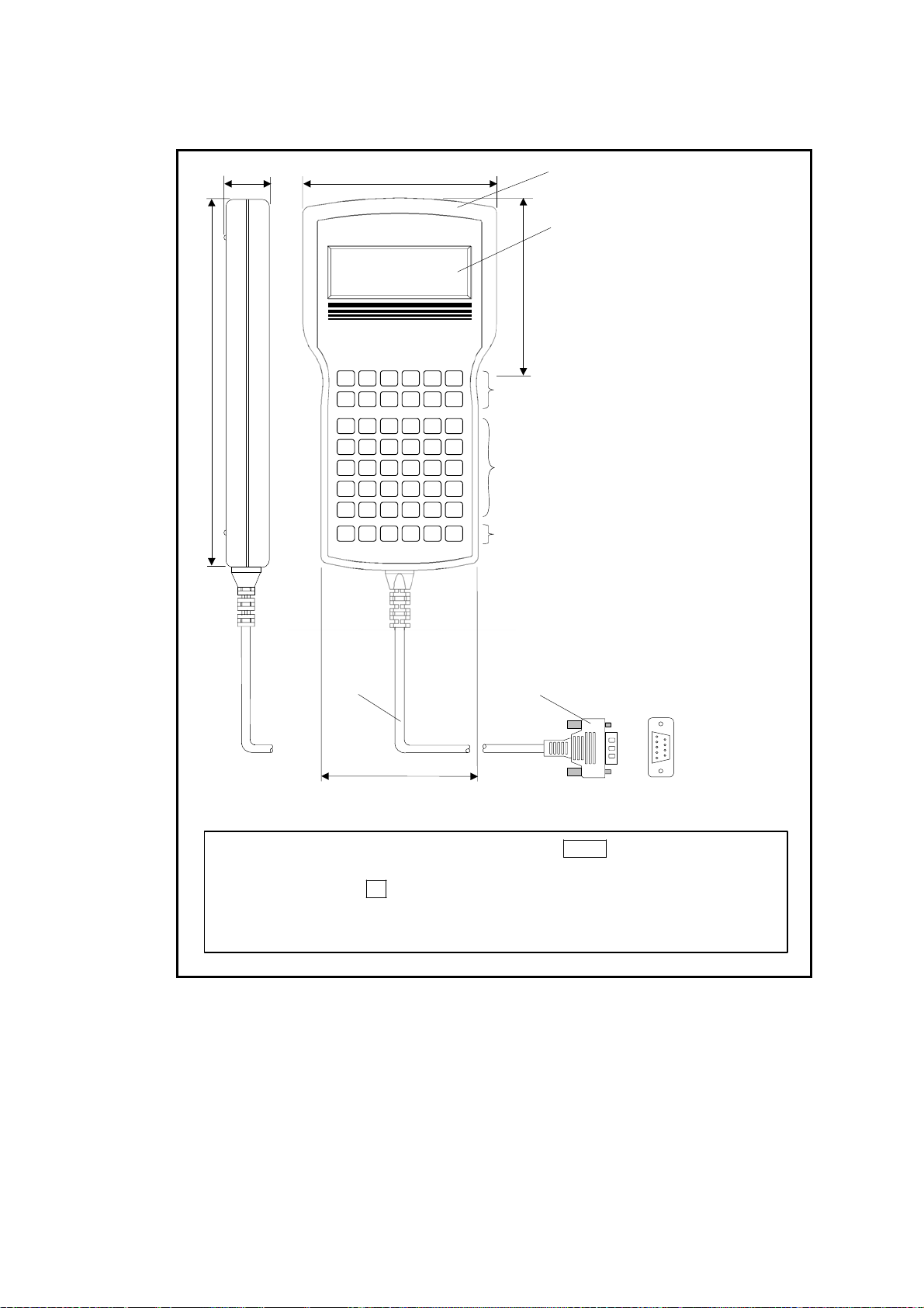
2.3.3. Handy Terminal
Note 1)
Fig 2-11: Handy Terminal M-FHT21
27
106
Frame
NSKNSK
LCD
90
HANDY TERMINAL
>
195
3 <2 $ 1 # - +5 %4
8 (7 ‘ 6 & . =0 ?9
CB A FED
IH G LKJ
ON M RQP
UT S XWV
?Z Y
CTRLESC SHIFT ENTSPBS
)
/
*
,
Numeric keys
Code keys (superscript)
Alphabetic keys
Special code keys
SHIFT : Shift key
ESC : Escape key (Not used)
CTRL : Control key
BS : Back space key
SP : Space key
ENT : Enter key
Note 2)
Note 4)
Note 5)
Note 3)
Cable
Connector
86
Note: (1) SHIFT: Press number key while pressing the SHIFT key to enter a code key
The superscript of each numeric key may be entered.
(2) BS: Press the BS key when cor recting logged in mistakes.
(3) SP: Use this key to input a blank between letters.
(4) ENT: Press the key at the end of a command or parameter setting.
— 2-8 —
Page 29

2.4. Standard Combination List
2.4.1. Motor and EDC Driver Unit Combinations
Table 2-2: Motor and EDC Driver Unit Combinations
Driver Unit
Motor
diameter
ø100
ø150
ø100
ø150
Motor
reference number
M-PS1006KN002
M-PS1012KN002
M-PS1018KN002
M-PS3015KN002
M-PS3030KN002
M-PS3060KN002
M-PS3090KN002
M-PS1006KN002
M-PS1012KN002
M-PS1018KN002
M-PS3015KN002
M-PS3030KN002
M-PS3060KN002
M-PS3090KN002
Reference number
¼¼ : code for specification
of included items.
M-EDC-PS1006AB502-¼¼ 200 to 230
M-EDC-PS1006CB502-¼¼ 100 to 115
M-EDC-PS1012AB502-¼¼ 200 to 230
M-EDC-PS1012CB502-¼¼ 100 to 115
M-EDC-PS1018AB502-¼¼ 200 to 230
M-EDC-PS1018CB502-¼¼ 100 to 115
M-EDC-PS3015AB502-¼¼ 200 to 230
M-EDC-PS3015CB502-¼¼ 100 to 115
M-EDC-PS3030AB502-¼¼ 200 to 230
M-EDC-PS3030CB502-¼¼ 100 to 115
M-EDC-PS3060AB502-¼¼ 200 to 230
M-EDC-PS3060CB502-¼¼ 100 to 115
M-EDC-PS3090AB502-¼¼ 200 to 230
M-EDC-PS3090CB502-¼¼ 100 to 115
M-EDC-PS1006ABC02-¼¼ 200 to 230
M-EDC-PS1006CBC02-¼¼ 100 to 115
M-EDC-PS1012ABC02-¼¼ 200 to 230
M-EDC-PS1012CBC02-¼¼ 100 to 115
M-EDC-PS1018ABC02-¼¼ 200 to 230
M-EDC-PS1018CBC02-¼¼ 100 to 115
M-EDC-PS3015ABC02-¼¼ 200 to 230
M-EDC-PS3015CBC02-¼¼ 100 to 115
M-EDC-PS3030ABC02-¼¼ 200 to 230
M-EDC-PS3030CBC02-¼¼ 100 to 115
M-EDC-PS3060ABC02-¼¼ 200 to 230
M-EDC-PS3060CBC02-¼¼ 100 to 115
M-EDC-PS3090ABC02-¼¼ 200 to 230
M-EDC-PS3090CBC02-¼¼ 100 to 115
Power
voltage[VAC]
Cable
reference number
M-C0¼¼SCP03
(Fixed type cable)
M-C0¼¼SCP13
(Flexible type
cable)
¼¼: Cable length
01: 1 [m]
02: 2 [m]
03. 3 [m]
04: 4 [m]
05: 5 [m]
06: 6 [m]
07: 7 [m]
07: 7 [m]
08: 8 [m]
09: 9 [m]
10: 10 [m]
15: 15 [m]
20: 20 [m]
30: 30 [m]
Remarks
• 256 channels
for internal
program.
• Pulse train
input
(Photo coupler)
• Compatible
with CC-Link
• 256 program
channels for
internal
program.
— 2-9 —
Page 30

2.4.2. Cable Set
Table 2-3: Reference Number of Cable Set
Function Cable length [m] Cable set reference number
1 M-C001SCP03
2 M-C002SCP03
3 M-C003SCP03
4 M-C004SCP03
5 M-C005SCP03
6 M-C006SCP03
Stationary cable
Flexible cable
7 M-C007SCP03
8 M-C008SCP03
9 M-C009SCP03
10 M-C010SCP03
15 M-C015SCP03
20 M-C020SCP03
30 M-C030SCP03
1 M-C001SCP13
2 M-C002SCP13
3 M-C003SCP13
4 M-C004SCP13
5 M-C005SCP13
6 M-C006SCP13
7 M-C007SCP13
8 M-C008SCP13
9 M-C009SCP13
10 M-C010SCP13
15 M-C015SCP13
20 M-C020SCP13
30 M-C030SCP13
2.4.3. Handy Terminal
Handy Terminal is required for inputting parameters and programs.
Table 2-4: Reference number of Handy Terminal
Handy Terminal reference number
M-FHT21
— 2-10 —
Page 31

2.5. Motor Specifications
r
r
2.5.1. PS Series Megatorque Motor
The PS Series Motors are common to all EDC Driver Units regardless of difference in 100 and
200 [VAC] power source voltages.
Table 2-5: Specifications of PS1 Motor
Reference numbe
Item [Unit]
Motor outside diameter [mm]
Maximum output torque [N•m]
Rated output torque [N•m]
Motor height [mm]
Hollow diameter [mm]
Maximum rotational speed
[s-1]
Rated rotational speed [s-1]
Resolution of position sensor
Absolute positioning accuracy
[count/
revolution]
[arc-sec]
Repeatability [arc-sec]
Allowable axial load [N]
Allowable radial load [N]
Allowable moment load [N•m]
Rotor inertia [kg•m2]
Allowable range of inertia
[kg•m2]
Mass [kg]
Environmental conditions
M-PS1006KN002 M-PS1012KN002 M-PS1018KN002
90 (Interchangeable type) (at ambient temperature of 25 ± 5[[°C]])
0.0024 0.0031 0.0038
0.0015~0.24 0.03~0.31 0.03~0.38
Ambient temperature: 0 to 40[[°C]]. Humidity: 20 to 80[%].
Indoor use only. Free from condensation, dust and corrosive gas. (IP30 equivalent.)
ø 100
6 12 18
2 4 6
85 110 135
ø 35
10
5
2 621 440
± 2
1 000 (Under no radial load)
820 (Under no axial load)
28
2.4 3.5 4.5
Table 2-6: Specifications of PS3 Motor
Reference numbe
Items [Unit]
Motor outside diameter [mm]
Maximum output torque
[N•m]
Rated output torque [N•m]
Motor height [mm]
Hollow diameter [mm]
Maximum rotational speed
[s-1]
Rated rotational speed [s-1]
Resolution of position sensor
Absolute positioning
accuracy
[count/
revolution]
[arc-sec]
Repeatability [arc-sec]
Allowable axial load [N]
Allowable radial load [N]
Allowable moment load
[N•m]
Rotor inertia [kg•m2]
Allowable range of inertia
[kg•m
Mass [kg]
Environmental conditions
M-PS3015KN002 M-PS3030KN002 M-PS3060KN002 M-PS3090KN002
15 30 60 90
5 10 20 30
85 102 136 170
90 (Interchangeable type) (at ambient temperature of 25 ± 5[[°C]])
2
]
0.011 0.014 0.019 0.024
0~1.1 0~1.4 0.12~1.9 0.12~2.4
5.5 6.9 11.0 13.8
Ambient temperature: 0 to 40[[°C]]. Humidity: 20 to 80[%].
Indoor use only. Free from condensation, dust and corrosive gas. (IP30 equivalent.)
SI Unit system: 1N = 0.102 kgf. 1N·m = 0.102 kgf·m
ø 150
ø 56
10 8 5
5 1 1
2 621 440
± 2
2 000 (Under no radial load)
1 700 (Under no axial load)
42
— 2-11 —
Page 32

2.5.2. Axial Load and Moment Load
The following show how to calculate axial and moment loads.
Fig 2-12: Load applied to a Motor
F
F
L
F
LA
(1) When F is the external force, then
Axial load Fa = F + weight of paylaod.
Moment load M = 0
!
Table 2-7: Dimension A (Distance between the bearing and the rotor surface)
(2) When an extyernal force is F, then
Axial load FA = F + weight of payload
Moment load M = F × L
(3) When an external force is F, then
Radial load Fr=F + weight of payload
Moment lo ad M = F × (L+A)
Caution : Axial load Fa, radial load Fr and moment load M shall be less than the
limits specified in the table 2-5 and 2-6 respectively.
M-PS3015KN002
M-PS3030KN002
M-PS3060KN002
M-PS3090KN002
Motor
reference number
Dimension A
M-PS1006KN002
M-PS1012KN002
M-PS1018KN002
30.2 32.9
— 2-12 —
Page 33

2.6. External Dimensions
2.6.1. PS Series Megatorque Motors
Fig 2-13: PS1 type Motor
Fig 2-14: PS3 type Motor
!
Caution : The bend radius of the motor cable lead (φ7) and the resolver cable
φ
lead (
!
Caution : Do not use the leads of the motor cable and the resolver cable with
flexing motion.
!
Caution : Do not add the stress (tension, vibration, etc) to the joint of the leads
and the connector. It causes the disconnection and the loose
connection.
7) should be R30 [mm] or more.
— 2-13 —
Page 34

2.6.2. EDC Driver Unit
Fig 2-15: EDC Driver Unit (Motor type: PS1006, PS1012, PS1018, PS3015, and PS3030)
Fig 2-16: EDC Driver Unit (Motor type: PS3060, and PS3090)
— 2-14 —
Page 35

Fig 2-17: Driver Unit compatible with CC-Link (Motor type: PS1006, PE1018, PS3015 and PS3030)
Fig 2-18: EDC Driver Unit compatible with CC-Link (Motor type: PS3060 and PS3090)
— 2-15 —
Page 36

2.6.3. Cable Set
!
Caution : If you connect the cable to a moving part, be sure to use a flexible type
2.6.3.1. Stationary Cable
!
Caution : Bending radius of Motor and resolver cables shall be R45 mm or over.
Fig 2-19: Cable Set (Fixed type: M-C×××SCP03)
cable.
2.6.3.2. Flexible Cable
!
Caution : The bending radius of Motor and resolver cables shall be R80 mm or
Fig 2-20: Cable Set (Flexible type: M-C×××SCP13)
over. The radius of cables at the connecting position shall be R40
mm or over.
— 2-16 —
Page 37

2.7. Driver Unit Specifications
Table 2-8: Specifications of EDC Driver Unit (1)
Item Specification
Motor type PS1006 PS1012 PS1018 PS3015 PS3030 PS3060 PS3090
Continuous output [Arms] 0.8 1.2 2.1 2.1 2.5 4.1 4.0
Output
current
Maximum output [Arms] 2.4 3.5 5.8 6.6 8.2 14.9 14.9
Rated capacity [VA] 0.3 0.4 0.5 0.5 0.8 0.4 0.6
Max. capacity [VA] 1.0 1.5 2.0 2.3 2.9 5.0 5.5
Control power
Input
power
Main power
Position sensor resolution [count/revolution] 2 621 440
Maximum velocity speed[s-1] 10 (Depends on the Motor type. Refer to “2.5. Motor Specifications.”)
Positioning operation mode
Pulse train command
Input signal
Control input
Position feedback
signal
Output
signal
Control output
Alarm
Monitors Analog monitor ×2, (Free range and offset setting), RS~232C monitor
Communication RS-232C serial communication (Asynchronous, 9600 bps)
Data backup EEPROM (Overwriting and deleting of parameters are limited to 100 000 times.)
Others
Field bus CC-Link Ver.1.10 compatible (optional)
*1: Change of function assignment of the Input/Output ports will make these functions effective.
*2: These control outputs become effective when these function is assigned to the output port.
Single phase 100 to 115 [VAC] / Single phase 200 to 230 [VAC]
50/60[Hz]Voltage Fluctuation: ±10[%] or less
Program operation (256 program channels), Pulse train command, RS-232C
serial communication command, Jogging, Home Return
Photo coupler input. Maximum frequency 1 MHz
Input format: CW/CCW, Pulse & direction or øA/øB
Resolution changer for free manipulation is available.
(1000 to 5 242 880 [count/revolut i on])
Photo coupler (± common), 17 inp ut po rt s. I np ut vol t a ge: 2 4 VDC
Emergency stop, Alarm clear, Over travel limit + direction, Over travel limit –
direction, Servo ON, Program operation start, Stop, Internal program channel
switching 0 to 7, Jog, Jog direction, (Hold, Velocity override, Integration OFF ,
Home Return start, and Home position limit)
*1
Signal format: øA/øB/øZ line driver. Free resolution setting to øA/øB is
available.
Resolution of øA/øB:
Shipping set: 20 480 [count/re volution] (Quadrupled: 81 920 )
Maximum: 1 310 720 [count/revolution] (Quadrupled: 5 342 880)
*Because the maximum frequency is 781 [kHz], the setting of the resolution
limits the maximum rotational speed. (Max. velocity = 781 [kHz]/
resolution of øA (øB)
Resolution of øZ: 80 [count/r evolution]
Photo coupler (± common), 8 output ports.
Max. switching capacity: 24 VDC/50 [mA]
Driver Unit ready, Warning, Over travel limit detection +/- direction, Servo
state, Busy, In-position, Target proximity A (Target proximity B, Zone A•B•C,
Travel limit +/-, Normal, Position error under/over, Velocity under/over,
Torque command under/over, Thermal loading under/over, Home Return
complete, Home position defined)
*2
Excess error, Program error, Automatic tuning error, Field bus warning,
Position command/Feedback error, Software thermal error, Home position
undefined, Main AC line under voltage, Travel limit over, RAM error, ROM
error, System error, Interface error, ADC error, Emergency stop, CPU error,
Field bass error, Position sensor error, Absolute position error, Motor cable
disconnected, Excess velocity, Resolver excitation amplifier alarm,
Commutation error, Overheat , Mai n AC line over voltage, Excess current,
Control AC line under voltage, Power module error
• Automatic tuning
• Function set to Input/Output ports available
• Temporal parameter setting by program is available
• Individual acceleration/deceleration setting
• Acceleration profiling
— 2-17 —
Page 38

Table 2-9: Specifications of EDC Driver Unit (2)
Environmental
conditions
Internal
function
Compatible
safety
regulation
Item Specification
Operating temperature
Storing temperature
Operation / storing
humidity
Vibration resistance
0 to 50[°C]
-20 to 85[°C]
90% or less. No condensation. 20 to 80% for storing (no condensation)
2
4.9 m/s
Optional dump resistor available when the regeneration current is beyond the
Regeneration
capacity of built-in resistor. (M-E014DCKR1-100, M-E014DCKR1-101) •
Connect to R+, R-, SE+ and SE-. (Never short-circuit them.)
Dynamic brake
UL
LVD
Functions at power-off, servo-off and an occurrence of alarm.
UL508C
EN50178
CE
EMC
EMI: EN55011 EMS: ENS61000-6-2
Connector
Mass [kg]
RS-232C CN1
Control I/O CN2
Position
sensor
CN3
Motor
Optional
CN4
regeneration
resister
Main/control
power source
CC-Link
option
CN5
CN6
PS1006, PS1012,
PS1018, PS3015,
PS3030
PS3060, PS3090
D-sub 9 pins
Standard specification: Half pitch connector 60 pi ns
CC-Link specification: Half pitch connector 10 pi ns
Half pitch connector 14 pins
Plastic connector (UL and CE compatible)
Plastic connector (UL and CE compatible)
Plastic connector 5 pins
Standard specification: 1.1
CC-Link specification: 1.3
Standard specification: 1.8
CC-Link Specification: 2.0
— 2-18 —
Page 39

2.8. RS-232C Interface Specifications
Refer to “8.9. RS-232C Communication” for specifications of RS-232C communication.
Refer to “Appendix 6. Wiring of RS-232C Communication Cable” for connecting with a control
device such as a personal computer.
◊ Optional RS-232C cable [M-C003RS03] is available from NSK.
2.8.1. CN1: RS-232C Serial Communication Connector
The optional Handy Terminal FHT 21 is available for the RS-232C communication terminal.
Table 2-10: Connector list
Driver Unit connector
Mating connector type
Mating connector shell type
* The user shall provide these connectors. They are not necessary if NSK Handy Terminal
2.8.1.1. CN1 Pin-Out
Fig 2-21: Pin-out
Japan Aviation Electronics Industry, Ltd.
FHT 21 is used.
DELC-J9SAF-13L9E or equivalent
DE-9PF-N* or equivalent
DE-C2-J6R* or equivalent
FG
+5V
RTS
SG
2.8.1.2. CN1 Signal List
Table 2-11: Signal list
Pin Signal name I/O Function
1
2 CTS
3 RXD
4 DSR
5 DTR
6 SG
7 RTS
8 +5V
9 FG
5
9
8
7
6
TXD Output Transmit data
DTR
4
DSR
3
RXD
2
CTS
1
TXD
Input Clear to send
Input Receive data
Input Data set ready
Output Data terminal ready
– Digital signal ground
Output Ready to send
Output Never connect
Frame ground (shield)
— 2-19 —
Page 40

2.9. Specifications of Control Input/Output Interface
2.9.1. CN2: Control Input/Output Signal Connector
The connector and the mating connectors to be used for the CN2 connector are listed in the
Table 2-12.
Table 2-12: Connector list
Connectors for Driver Unit
Mating connectors
Mating connector shell type
Molex Inc.
52986-5079 or equivalent
54306-5019 or equivalent
54331-0501 or equivalent
The following are wiring precautions for the connector CN2.
1) Use shielded cable for wiring of the CN2 connector.
2) Be sure to use twisted cables for the pulse train input and the position feed back
signals.
Wiring length shall be short as possible. (2 [m] maximum)
3) These cables should be laid separately from the main power line.
4) Connect one end of the shielded cable to the frame ground. Refer to “3.3.3. Ground
Connection and Wiring” for the way of connection.
!
Caution : Check for wiring mistake in the polarity of external power supply and
shorting between connector pins.
!
Caution : Never connect the idle pins that are instructed as “Do not connect.”
Do not treat the idle pins as instructed at the master controller (PLC,
etc) side after you have connected all pins of the CN2 connector.
◊ Connection of an idle pin that is clearly instructed not to connect
may make the external noise easily affect the Driver Unit, and may
lead to malfunction or breakdown of the Driver Unit.
— 2-20 —
Page 41

2.9.1.1. CN2 Pin-Out
The pin-out arrangement below is for the shipping set. The function of each signal port may be
changed by the function setting of control Input/Output ports.
Fig 2-22: Pin-out (shipping set)
Input dedicated to safety function Output dedicated to safety function
EMST : Emergency stop
General input
EMST : Emergency stop
ACLR : Alarm clear
OTP : Travel limit, + direction
OTM : Travel limit, – direction
SVON: Servo on
RUN : Pos itioning s tart
STP : Stop
PRG0: Internal program channe l selection 0
PRG1: Internal program channe l selection 1
PRG2: Internal program channe l selection 2
PRG3: Internal program channe l selection 3
PRG4: Internal program channe l selection 4
PRG5: Internal program channe l selection 5
PRG6: Internal program channe l selection 6
PRG7: Internal program channe l selection 7
JOG : Jogging
DIR : Jogging direction
HLD : Hold
ORD : Velocity override
IOFF : Integration off
HOS : H o me Return s ta r t
HLS : Home position limit
NONE: (Set to a no-function port)
1
2
DC24
4
PI1
(ACLR)
6
PI3
(OTM)
8
PI5
(RUN)
10
-
12
PI8
(PRG1)
14
PI10
(PRG3)
16
PI12
(PRG5)
18
PI14
(PRG7)
20
PI16
(DIR)
22
CWP+
24
CCWP+
DC24
3
PI0
(EMST)
PI2
(OTP)
7
PI4
(SVON)
9
PI6
(STP)
11
PI7
(PRG0)
13
PI9
(PRG2)
15
PI11
(PRG4)
17
PI13
(PRG6)
19
PI15
(JOG)
21
-
23
CWP-
25
CCWP-
27
COM
29
PO1
(WRN)
31
PO3
(OTMA)
33
PO5
(BUSY)
35
PO7
(NEARA)
37
*CHA
39
*CHB
41
*CHZ
43
SGND
45
-
47
-
49
-
5
26
COM
28
PO0
(DRDY)
30
PO2
(OTPA)
32
PO4
(SVST)
34
PO6
(IPOS)
36
CHA
38
CHB
40
CHZ
42
-
44
-
46
-
48
-
50
-
Note:1) Function in brackets is the shipping set
2) The pins with hyphen is prohibited.
DRDY : Driver Unit ready
NRM : Normal
General output
DRDY : Driver Unit ready
WRN : Warning
OTPA : Travel limit detection, + direction
OTMA : Travel limit detection, - direction
SVST : Servo state
BUSY : In-operation
IPOS : In-position
NEARA : Target proximity A
NEARB : Target proximity B
ZONEA : Zone A
ZONEB : Zone B
ZONEC : Zone C
TEU : Pos i tio n e rr o r u nder
TEO : Position e rr o r o v e r
TVU : Velocity under
TVO : Velocity over
TTU : Torque com mand under
TTO : Torque comm and over
TJU : Thermal loading under
TJO : Thermal loading over
OTXA : Travel limit ditection, ± direction
NRM : Normal
HOME : H o me Return c o mplete
HCMP : Home position defined
NONE : Mask function
PI0 and PO0 are the dedicated ports to the safety function input and output respectively.
◊ You cannot change the function setting to the PI0 (Pin number 3: EMST input
[Emergency stop]). You may only set the logic of the connector and the stability timer
to it.
◊ You can only change the function of the PO0 (Pin number 28: DRDY output [Driver
Unit ready]) to the function NRM (normal) output. You cannot set the output logic and
the stability timer to it.
— 2-21 —
Page 42

2.9.1.2. CN2 Signal List
!
Caution : Follow the specification documents for the specially ordered System
!
Caution :Never connect the idle pins that are instructed as “Do not connect.”
Table 2-13: Signal list (Shipping set)
Input
Output
Input
Port
Pin
code
No
1 - DC24 2 - DC24 -
3 PI0 EMST
4 PI1 ACLR
5 PI2 OTP
6 PI3 OTM
7 PI4 SVON
8 PI5 RUN
9 PI6 STP
10 - - 11 PI7 PRG0
12 PI8 PRG1
13 PI9 PRG2
14 PI10 PRG3
15 PI11 PRG4
16 PI12 PRG5
17 PI13 PRG6
18 PI14 PRG7
19 PI15 JOG
20 PI16 DIR
21 – – –
22 – CWP+ –
23 – CWP- –
24 – CCWP+ –
25 – CCWP- –
Signal
code
when its settings of Inputs and Outputs are different from the standard.
Do not disconnect the idle pins at the master controller (PLC, etc) side
after you have connected all pins of the CN2 connector. It causes the
malfunction and the breakdown.
Contact
logic
Normally
closed
Normally
open
Normally
closed
Normally
closed
Normally
open
Normally
open
Normally
open
Normally
open
Normally
open
Normally
open
Normally
open
Normally
open
Normally
open
Normally
open
Normally
open
Normally
open
Normally
open
24 VDC external power supply External power supply for input signal
24 VDC external power supply External power supply for input signal
Emergency stop
Alarm clear Clears warning.
Over travel limit, + direction
Over travel limit, - direction
Servo-on
Start program
Stop
Do not connect
Internal program channel selection 0
Internal program channel selection 1
Internal program channel selection 2
Internal program channel selection 3
Internal program channel selection 4
Internal program channel selection 5
Internal program channel selection 6
Internal program channel selection 7
Jogging
Jogging direction Specifies the direction of jogging.
Do not connect
CW pulse train (+)
CW pulse train (-)
CCW pulse train (+)
CCW pulse train (-)
Signal name Function
Terminates positioning operation and the
Motor stops by the dynamic break.
If OTP goes active, the Motor servo is
locked in the CW direction.
If OTM goes active, the Motor servo is
locked in the CCW direction.
If SVON goes active, the servo turns on and
the System waits for a command to be
entered.
Starts program operation specified by the
PRG input.
Stops positioning operation and execution of
the program.
-
For a program positioning operation:
A combination of ON OFF of PRG0 to
PRG7 inputs specifies a channel (0 to 255)
to be executed.
If JOG goes active, the Motor rotates If it
goes inactive, the Motor decelerates and
stops.
-
Pulse train
command rotates the
Motor in the CW
direction.
Pulse train
command rotates the
Motor in the CCW
direction.
• Selection of Step
and Direction or
øA/øB format is
available.
• Free setting of pulse
input to a circular
division is available.
— 2-22 —
Page 43

Input
Output
Table 2-13 (continued): Signal list (Shipping set)
Pin
No.
Port
code
Signal
code
Contact
logic
Signal name Function
26 – COM –
27 – COM –
28 PO0 DRDY Positive
29 PO1 WRN Negative
30 PO2 OTPA Negative
31 PO3 OTMA Negative
32 PO4 SVST Positive
33 PO5 BUSY Positive
34 PO6 IPOS Positive
35 PO7 NEARA Positive
Output
36 – CHA –
37 –
38 – CHB
39 –
40 – CHZ
41 –
42 –
43 – SGND
44
45
46
47
48
49
50
*CHA
*CHB
*CHZ
–
– –
– –
– –
– –
– –
– –
– –
Output signal common
Common for output signal.
Output signal common
Reports that the Motor is ready to rotate.
Driver Unit ready
(Those pins are open when the Motor is not
ready or an alarm occurs.)
Warning Warns abnormality in the System.
Over travel limit (+ direction)
detected
Over travel limit (- direction)
detected
Reports the output of over travel limit
(software and hardware) in the plus direction.
Reports the output of over travel limit
(software and hardware) in the minus
direction.
Servo state Reports the state of servo.
In-operation Reports the state of positioning operation.
In-position
Target proximity A
Position feedback signal øA
Position feedback signal ø*A
–
Position feedback signal øB
–
Position feedback signal ø*B
–
Position feedback signal øZ
–
Positioning feedback signal ø*Z
–
–
Signal ground Ground for the position feedback signal.
–
Do not connect. –
Reports the condition of positioning error
and the positioning operation.
Reports that the Motor is approaching to the
destination.
A pulse signal that reports the number of
rotations of the Motor.
Free setting of output resolution in øA/øB
phase is available.
Do not connect. –
Do not connect. –
Do not connect. –
Do not connect. –
Do not connect. –
Do not connect. –
Do not connect. –
— 2-23 —
Page 44

Table 2-14: Expanded function for function assignable control Input/Output
Input
Output
Input
Output
Function
code
HLD
ORD
IOFF
HOS
HLS
NEARB
ZONEA
ZONEB
ZONEC
TEU
TEO
TVU
TVO
TTU
TTO
TJU
TJO
OTXA
NRM
HOME
HCMP
Function name Description
Hold
Velocity override
Pauses the Motor operation and execution of the
program.
Changes the velocity command in a rate of the
specified velocity.
Integration OFF Terminates velocity integration control.
Home Return start Starts Home Return operation.
Home position limit Reports that the Motor is nearing to the Home position.
Target proximity B
In-Zone A
In-Zone B
In-Zone C
Position error, under
Position error, over
Velocity error, under
Velocity error, over
Torque command, under
Torque command, over
Thermal loading, under
Thermal loading, over
Travel limit switch,
± direction
Reports that the Motor is nearing to the target position
B.
This signal reports the Motor has entered in a preset
zone.
Reports condition of position error against the
threshold value.
Reports condition of velocity error against the
threshold value.
Reports condition of Driver torque command against
the threshold value.
Reports condition of thermal loading against the
threshold value.
Reports detection of limit switch in + or – direction
(hardware and software).
Normal Reports detection of alarm or warning.
Home return completed
Reports that the Motor has completed Home Return
and is on the Home position.
Home position defined Reports that the Home position has been defined.
— 2-24 —
Page 45

2.9.2. CN2 Interfacing
2.9.2.1. General Input Signal Applied inputs: SVON, EMST, OTP, ACLR, PRG0 to PRG7, JOG, DIR, and STP
Table 2-15: General specifications
Item Specification
Input voltage
Input impedance
Maximum current
Fig 2-23
24 VDC ± 10%
3.9 kΩ
10 mA or less (per input)
∗
24 VDC
input
3.9 kΩ
560 Ω
Driver Unit side
* You may reverse the polarity of the external power supply and connect as
“minus • common.”
— 2-25 —
Page 46

2.9.2.2. Pulse Train Input Signal
Ω
Ω
Applied inputs: CCWP +, CCWP -, CWP +, and CWP -
Table 2-16
Item Specification
Input voltage
Input impedance
Maximum current
Fig 2-24: Pulse train input
5 VDC ±10%
220 Ω
25 mA or less
Input +
Input -
Driver Unit side
220
Ω
1 kΩ
1) Connection with the line driver output.
Connect directly to the input ports.
Fig 2-25: Connection with the line driver output.
Input+
Input-
User’s controller side
220
Driver Unit side
1 KΩ
2) Connection with the open collector output.
Please insert a resistor (68 [Ω],1/8 [W]) into the circuit as shown below.
Fig 2-26: Connection with the open collector output
+ 5 V
68
Ω
User’s controller side
Input
Input
+
-
220
1 kΩ
Driver Unit side
— 2-26 —
Page 47

2.9.2.3. Output Signal Applied output: PO0 to PO7 (Shipping set: DRDY, WRN, OTPA, OTMA, SVST, BUSY, IPOS,
Table 2-17: General output photo coupler specification
Fig 2-27
Output
∗
COM
and NEAR)
Item Specification
Maximum load capacity
Maximum saturated voltage
~ +
~ -
24 VDC/50 mA
2 V or less
Driver Unit side
*You may reverse the polarity of the external power supply and
connect as “minus • common.”
2.9.2.4. Position Feedback Signal Output Applied output: CHA, CHB, CHZ, *CHA, *CHB, and *CHZ
Table 2-18: Specifications of position feedback output signal
Item Specification
Output format
Line driver
Recommended line receiver
Fig 2-28: Position feedback signal output
CHA
CHB
CHZ
∗ CHA
∗ CHB
∗ CHZ
Line driver (CHA, CHB, CHZ, *CHA, *C H B and *CHZ)
Texas Instruments: AM26C31 or equivalent
Texas Instruments: AM26C32 or equivalent
SGND
Driver Unit side
— 2-27 —
Page 48

2.9.2.5. Analog Monitor Output
Table 2-19: Analog monitor specification
Output format
Maximum output
voltage
Saturated current
Fig 2-29: Analog monitor
Item Specification
MON1,2
GND
Op-amp
5 V
4 mA or less
-
+
— 2-28 —
Page 49

2.10. CN3: Resolver Cable Connector
!
Caution : Connect the Cable Set provided with the Driver Unit. Do not cut or
hookup to other cable because the Cable Set is uniquely made for the
position sensor.
Table 2-20: Connector list
Driver Unit connector
Mating connector type*
Mating connector shell type*
* Provided with the Cable Set.
2.10.1. CN3 Pin-Out
Fig 2-30: Pin-out
Molex Inc. 52986-1479 or equi val ent
Molex Inc. 54306-1419* or equivalent
Molex Inc. 54331-0 141* or equivalent
1
2
INC-B
4
–
6
ABS-B
2.10.2. CN3 Signal List
Table 2-21: Signal list
8
INC-A
3
INC-C
5
ABS-A
7
ABS-C
9
INCCOM
11
–
13
–
ABSCOM
10
–
12
–
14
FG
Pin Signal name Function
1
2
3
5
6
7
8
9
14
INC-A Incremental resolve signal øA
INC-B Incremental resolver signal øB
INC-C Incremental resolver signal øC
ABS-A Absolute resolver signal øA+
ABS-B Absolute resolver signal øB+
ABS-C Absolute resolver signal øC+
ABC-COMMON Absolute resolver common
INC-COMMON Incremental resolver common
FG Frame ground
!
Danger : Never connect pins not listed above.
!
Danger : Check orientation of the connector when inserting it. Tighten the
screws to secure the connector so that it does not disconnect because
of shock or pulling.
!
Danger : Do not connect or disconnect the cable when the power of the Driver
Unit is on.
— 2-29 —
Page 50

2.11. CN4: Motor Connector
!
Caution : Use the Cable Set provided with the Driver Unit. Please do not cut the
cable or hookup to other cable because the Cable Set is specially
made for the position sensor.
Table 2-22: Connector list
Connector of Driver Unit
Mating connector
* Provided with the Driver Unit.
2.11.1. CN4 Pin-Out
Fig 2-31: Pin-out
WAGO Corporation 232-268 or equivalent
WAGO Corporation 231-638 or equivalent
1
2
3
4
5
6
7
8
2.11.2. CN4 Signal List
Table 2-23: Signal list
Pin
No.
1 U
2 V
3 W
5 R+
6 R7 SE+
8 SE-
* Short these pins if external dump resistor is not in use. If they remain open, the alarm of
“over heat” occurs.)
U
Motor winding ø U
V
Motor winding ø V
Motor winding ø W
W
R+
External dump resistor terminal
R-
External dump resistor terminal
SE+
External dump resistor thermal sensor input*
SE-
External dump resistor thermal sensor
Signal
name
Motor winding ø U
Motor winding ø V
Motor winding ø W
External regeneration resistor terminal
External regeneration resistor terminal
External regeneration resistor thermal sensor input*
External regeneration resistor thermal sensor input*
Function
!
Danger : Do not connect or disconnect the connector when the power of the
Driver Unit is on.
!
Danger : A high voltage is applied to the connector after the power is turned on.
Take extra care for short circuit.
!
Danger : Check the orientation of the connector when inserting it. Though the
connector is self-lock type, be sure to insert it to the bottom. Otherwise
you cannot secure the connector.
!
Danger : A high voltage remains between the pins R+ and R- even the main
power is turned off. Be careful not to get an electric shock.
— 2-30 —
Page 51

2.12. CN5: Connector for Power Supply
The table below shows the connectors for CN5 and the connector of user device.
Table 2-24: Connector list
Connector of Driver Unit
Mating connector
2.12.1. CN5 Pin-Out
Fig 2-32: Pin-out
5
4
3
2
1
L
N
L
N
2.12.2. CN5 Wiring Diagram
Fig 2-33: Wiring diagram
In case of 200 [VAC]
WAGO Corporation 231-565/001-000 or equivalent
WAGO Corporation 231-305/026-000 or equivalent
Control power
Main power
CN5
CTRL
200-230 [VAC]
MAIN
200-230 [VAC]
L
N
L
N
Control power
Single phase 200 [VAC]
Main power
Single phase 200 [VAC]
In case of 100 [VAC]
CN5
CTRL
100-115 [VAC]
MAIN
100-115 [VAC]
L
N
L
N
Control power
Single phase 100 [VAC]
Main power
Single phase 100 [VAC]
— 2-31 —
Page 52

(Blank Page)
— 2-32 —
Page 53

3. Unpacking, Installation and Wiring
3.1. Unpacking
3.1.1. Receiving Check
Make sure you have received the following units.
1) Megatorque Motor
2) Driver Unit
3) Cable Set (Motor and Resolver cable)
3.1.2. Motor and EDC Driver Unit Combinations
!
Caution : Confirm that the reference number of the Motor and the Driver Unit on
each nameplate matches each other in the following codes: Motor
series and size, and maximum torque.
Fig 3-1: Indication on the nameplate of Motor
MODEL
M-PS 1 006 KN002
Motor series code
Motor size code
Fig 3-2: Indication on the nameplate of Driver Unit
Moter series code
Motor size code
Type
Maximum output torque
Maximum output torque
**
NO.
PS1-11001
Serial number
No.
PS1-11020 EDC- PS 1 006 A B 5 02-
(This part is blank depending
on some version.)
Serial No.
— 3-1 —
Page 54

3.2. Installation
Note
r
3.2.1. Motor Mounting
Please follow the notes described below to make full use of the capabilities of the PS series
Megatorque Motor, a highly capable DD (direct drive) motor series.
3.2.1.1. Environmental Conditions of Motor
Use the Motor in the indoor condition free from corrosive gas.
The operating ambient temperature for the Motor shall be 0 to 40[°C].
The PS series Motor is neither dust-proof nor waterproof. (IP30 equivalent)
Do not expose the Motor to water or oil from any source.
3.2.1.2. Motor Installation
Install and secure the Motor on a rigid base, otherwise mechanical vibrations may occur.
!
Warning : Mount the motor using the tapped or through holes.
The mounting surface flatness should be lesse than 0.02 [mm].
The Motor can be installed either horizontally or vertically.
Figure 3-3: Mounting Motor
: If the motor is installed as indicated in the figure below, mechanical vibrations will be
generated and the velocity loop proportional gain(VG)cannot be increased. It will occu
overshoot and the motor can not operate smoothly.
• Attach the load directly to the Motor rotor.
• Mount the motor directly to the base.
The load is not attached directly to
the roto r.
The M o tor is not m o unted
directly on the mounting
base.
Fixing bolt
Table
Megatorque
Motor
Mounting base
Megatorque
Motor fixing bolt
Motor
Flatness of mounting surface shall be
0.02 mm or less.
Load
Mounting base
!
Caution : The bend radius of the motor cable lead and the resolver cable lead
should be R30 [mm]
or more.
Do not use the leads of the motor cable and the resolver cable with
flexing motion.
— 3-2 —
Page 55

3.2.1.3. Coupling Load to Motor
!
Warning : Fix the load using the bolt-holes of the rotor. Take a great care for play
between the rotor and the load.
◊ The following are the maximum tightening torque of fixing bolts
(1) PS 1 Motor: 3.4 N•m (M4 bolt)
(2) PS 3 Motor: 7.8 N•m (M6 bolt)
!
Caution : When you use pin holes on the rotor (output axis) of PS3 Motor, follow
the notes below.
◊ Set the tolerance quality of locating pin diameter for running fit.
◊ Do not apply excessive force or shock to the Motor when inserting a locating pin.
◊ The function of the pinholes is simply to adjust the position of a mating part with the
Motor. Do not use the pinholes to lock the mating part (load).
3.2.1.4. Confirmation of Use Conditions
The load moment of inertia is generally much bigger than the rotor moment of inertia in the
Megatorque Motor System. The table below shows the approximate inertia capacity of each
Motor size.
Table 3-1: Maximum load inertia of Megatorque Motor
PS1006
PS1012
PS1018
PS3015
PS3030
PS3060
PS3090
!
◊ Refer to “2.5. Motor Specifications” for the allowable axial load, allowable radial load
3.2.1.5. Dummy Inertia
For the full use of the benefits of the direct drive motor system, it is essential to maximize the
resonance frequency of the whole mechanism by increasing the rigidity of the load, as well as
securely fastening the Motor to a highly rigid mechanical system. Therefore, adding some
dummy load to the rotor directly may help in the following cases.
Rotor inertia
2
[kg•m
]
0.0024 0.23
0.0031 0.30
0.0038 0.37
0.011 1.0
0.014 1.3
0.019 1.8
0.024 2.3
Warning : Check if the use conditions exceed the allowable axial load and the
allowable moment load of the Motor.
and the allowable moment load.
Maximum load inertia
[kg•m2]
(1) A key is used to fix the load to the rotor because the load cannot be directly attached to
the rotor.
(2) The load is directly fixed to the rotor. However, vibration occurs due to torsional
deflection on the rotary axis of the load.
(3) Inertia of the whole mechanism is very low when a thin shaft such as a ball screw shaft
is attached.
(4) There exists play because a sprocket chain or a gear train is used.
— 3-3 —
Page 56

Inertia of a dummy load shall be approximately 20% of the load moment of inertia.
When a speed reducer mechanism is used, it shall be
2
GD
/(r2 × GD
1
Where GD
2
) ≤ 5
d
2
= inertia of indirectly connected load, GD
1
2
= inertia of directly attached
d
load, and r = reduction ratio.)
Fig 3-4: Example of dummy load
3.2.2. Installation of Driver Unit
The EDC Driver Unit must be fixed so that fins are in the vertical position for natural
air-cooling.
!
Caution : (1) Ambient temperature
(2) Dust-proof • Waterproof
Load
Dum my load
Megatorque
Motor
Ambient temperatures should be in a range from 0 to 50 [[°C]]. The
Driver Unit cannot be used in excess of 50 [[°C]]. A sufficient space
of at least 100 [mm] should be provided both above and below the
Driver Unit in a control cabinet. Operate the Driver Unit in an
environment in which internally generated heat can be dissipated. If
heat is trapped above the Driver Unit, open the space above it to
allow for the heat to dissipate (in this case, also take steps to
prevent the entry of dust) or provide a forced air cooling system.
◊ Use the Driver Unit in a control cabinet with IP54 or higher. Protect
the Driver Unit from exposure to oil mist, cutting water, cutting dust,
coating gas, etc., to prevent their entry into the Driver Unit through
ventilation openings, which may cause circuit failure.
◊ IP code is specified in the IEC standard and classifies the
protection level of enclosures from the solid contaminant and
water.
◊ Explanation of IP54:
• Code 5: Dust-proof (protection against external solid contaminant)
• Code 4: Waterproof (must not be affected by water splash in any
direction.)
!
Caution : When installing two or more Driver Units for multi-axis combinations,
provide a 10 mm or more space between adjacent Driver Units.
Maintain inside temperature of the enclosure into which the Driver Unit is installed between 0 to
50[°C]. If the alarm P0 (Over heat) occurs frequently, provide a forced cooling to the heatsink.
Refer to “11. Alarm and Warning” for details.
The Driver Unit can be attached to a panel using front mounting brackets (optional).
The maximum power loss of the EDC Driver Unit is 55 W.
— 3-4 —
Page 57

Fig 3-5: Installation of Driver Unit
3.3. Wiring
3.3.1. Connection of Cable Set
100 mm or more
100 mm or more
!
Caution : Do not cut the Motor cable to change the length shorter or longer or do
not hook it up to other cable. You need to separately purchase the
cable with specified length.
The standard cable length is available in 1 to 10 meters (in increment
of 1 meter), and in 15, 20 and 30 meters.
!
Caution : Do not place the power lines (AC main power and Motor cable) and the
signal lines in close proximity. Do not tie wrap them and not to put in
the same duct or conduit.
Fig 3-6: PS series Megatorque Motor
To CN3
To ground ter minal
To CN4
— 3-5 —
Page 58

3.3.2. Connecting Power
Refer to “2.10. CN5: Connector for Power Supply” for details.
Use AWG16 of anti-heat vinyl UL cables for the power supply.
Do not place the main power AC line cable and the signal wires in close proximity. Do not tie
wrap them, and do not put them in the same duct or conduit.
Separate the wiring of the primary and the secondary noise filters, and take different routing.
The Driver Unit and the noise filters shall be close to each other.
Be sure to install the surge killer circuit to the coils of magnetic switch, relay and solenoid. Refer
to catalogs of each manufacturer for more details.
An inrush current flows when the power is turned on because of the capacitive load connected to
the main power supply circuit. For this reason, use the contacts such as a magnetic switch that
has a higher rated current as shown below.
Table 3-2: Noise filter requirement [Reference only][Recommended manufacturer: Schaffner]
Power source Type Rated voltage Rated current
Single phase
100 or 200 [VAC]
FN2070-10 250 [VAC] 10 [AAC]
Table 3-3: Capacity of circuit breaker for power supply
Contacts Rated current
Non-fuse breaker
Short circuit breaker
Magnetic switch
10 A
10 A, Sensitivity: 15 mA
10 A
Table 3-4: Inrush current
Inrush current (Typical)
Item
Control power
Main power
!
Caution : Do not lose the screws of the ground terminal when wiring the
Power supply
100 [VAC]
7.5 A 15 A 10 msec
10 A 20 A 10 msec
Power supply
200 [VAC]
connector.
Refer to Figure 3-7 for wiring the power.
Time
— 3-6 —
Page 59

3.3.3. Ground Connection
∗1
∗1
I
l
V
Y
V
For grounding the Driver Unit, use braided copper cable or heavy gage cable as possible such as
AWG12 or larger.
The ground terminal is M4 screw. There is a possibility that the thread of a screw is damaged
when the tightening torque of the screw exceeds maximum value 1.2N・m.
!
Caution : Ground the Motor separately when it is isolated from the machine into
!
Warning : All the ground lines must be connected at one point and the grounding
Fig 3-7: Wiring example of power supply
which it is installed.
resistance shall be 100 Ω or less.
AC power
Ground earth
Class D
or better
ELB1
CB1
∗1
NF
∗1
Connect at one point.
∗1:
NF1
CN5
MC1
∗1
FG
∗1
SW1 SW2
MC1RY1
Master controller
• Controller (pulse train output)
• Sequencer
24 VDC
power supply
MC1
Driver Un it
CN3
Control power
CN4
Main power
CN2
nput signa
+ 24
+ 24
GND
Resolver
Motor
DRD
COM
RY1
ELB1: Short circuit brea ker
CB1: No fuse breaker
NF1: Noise filter
MC1: Magnetic switch
RY1: Relay
SW1: Main power switch ON
SW2* Main switch OFF
Caution : We recommend the noise filter below for compliance with the EMC
!
Directive.
◊ FN2070-10/06 (Schaffner EMC Ltd.) or equivalent.
(Use a breaker compatible with the European Safety Directives.)
!
Caution : Provide a circuit to shut down the main power by the output of an
alarm.
◊ When an alarm occurs, the output DRDY (Driver Unit ready) of the
connector CN2 opens.
The Driver Unit gives the warning P5 (Main AC line low voltage) when the main power is
turned off while the servo is on. [For the main power ON/OFF, refer to “7.1.1. Servo on:
SVON.”]
◊ Input of ACLR (Alarm clear) signal, the command CL (Alarm clear), or turning on the
control power again will clear the alarm.
— 3-7 —
Page 60

3.3.4. Connector Wiring
!
Caution : Be sure to install a surge killer circuit when inductive switches such as
!
Caution : When inputting the inputs “Over travel limit, + direction” and “Over
relays are used.
travel limit, - direction,” connect the outputs of your sensors directly to
the inputs, not via the master controller. (Those connectors are shown
as
in Figure 3-8 below.)
— 3-8 —
Page 61

3.3.4.1. Wiring Example (CN2)
Fig 3-8: CN2 wiring example
Polarity of the power supply may be
reversed to minus common.
24 VDC
Over travel limit, + direction
Over travel limit, – direction
Internal program channel selection 0
Internal program channel selection 1
Internal program channel selection 2
Internal program channel selection 3
Internal program channel selection 4
Internal program channel selection 5
Internal program channel selection 6
Internal program channel selection 7
5 VDC
CCW pulse train
Over travel limit detection, + direction
24 VDC
Over travel limit detection, – direction
Polarity of the power supply may be
reversed to minus common.
Position feedback signal øA
Position feedback signal øB
Position feedback signal øZ
User’s controller EDC Driver Unit
Servo ON
Emergency stop
Alarm clear
Start positioning
Jog direction
CW pulse train
Driver Unit ready
Warning
Servo ON state
State of operation
In position
Target proximity A
Signal ground
Stop
Jog
FG
CN2
1,2 DC24
7 SVON
3 EMST
4 ACLR
5 OTP
6 OTM
8 RUN
9 STP
11 PRG0
12 PRG1
13 PRG2
14 PRG3
15 PRG4
16 PRG5
17 PRG6
18 PRG7
19 JOG
20 DIR
22 CWP+
23 CWP–
24 CCWP+
25 CCWP–
28 DRDY
29 WRN
30 OTPA
31 OTMA
32 SVST
33 BUSY
34 IPOS
35 NEARA
26,27 COM
36 CHA
37 ¼CHA
38 CHB
39 ¼CHB
40 CHZ
41 ¼CHZ
43 SGND
— 3-9 —
Page 62

3.4. Turning on Main Power
3.4.1. Precautions Before Power-on
!
Caution : Before turning on the power check the following. Improper connection
may result in breakage of the Driver Unit.
(1) Connections of each cable.
(2) Connection of the Handy Terminal
(3) Confirm the safe conditions.
!
Danger : The operator shall be out of the Motor motion range.
!
Warning : The Motor must be securely fastened to the machine base.
!
Warning : The load (work) must be securely fastened to the Motor.
!
Danger : There shall be no mechanical interference when the Motor makes a full
turn
!
Caution : Turn on the power when the Motor is stationary. Otherwise the System
cannot detect the position coordinates and the alarm A1 (Absolute
position error) occurs.
— 3-10 —
Page 63

3.4.2. Points to be Checked When Power-on
g
T
d
(1) Turn on the power and confirm that the LED on the front panel indicates the normal state of the
System.
Fig 3-9: When error occurs Fig 3-10: In normal state
7segments LED: Identifies a type of alarm.
It indicates a type of alarm in 2 digit
numbers. The numbers will be dispalyed
in time sharing.
If two or more errors occurs, the LED
indicates them in the same manner as
described above.
Power LED: It tuns on when the pwoeris on.
Normal state: Green
Error occurs: Orange
Power LED: Turns on when the power
turns on.
• Normal state: Green • Error: Oran
e
(2) Check if the Emergency stop (CN2, pin #3: EMST) input is effective.
• When the emergency stop input is ON, the 7 segments LED on the front panel indicates the
alarm code in the order of F
!
Warning : The shipping set of the EMST input (EMST) is a normally closed
→ 4 . If not, refer to “11. Alarm and Warning”
contact. If it is not connected, the alarm F4 (Emergency stop) occurs.
Wire the EMST circuit or change the polarity to a normally open contact
referring to “3.4.3. Polarity Setting of Control Input Port” to clear the
alarm.
!
Warning : The shipping set of the inputs OTP and OTM (Over travel limit) are the
normally closed contact. It will cause an alarm if they are not connected.
Wire them or change the polarity to the normally open contact referring
to “3.4.3.Polarity Setting of Control Input Port” to clear the alarm.
(3) The System is in the normal state when the display of the Handy Terminal shows the prompt
“: (colon)” after the message of “NSK MEGATORQUE.”
Fig 3-11: Indication of the display of the Handy Terminal
NSK MEGATORQUE
XSY*****.*,XOP*
DC1A80_*****.*
he part represented by (*)
epends on the System type.
:_
— 3-11 —
Page 64

3.4.3. Polarity Setting of Control Input Port (Normally Open Contact and Normally Closed Contact)
The shipping set of the inputs EMST, OTP, and OTM of the CN2 connector is the normally
closed contact. The following show how to change the polarity of the above inputs to the
normally open contact.
!
Caution :You cannot change the polarity of a control input port when the Motor
servo is on. Be sure the servo is off when changing the polarity.
◊ Input the command MO (Motor off) to turn the Motor servo off.
M
O
ENT
:MO
:_
The following describe how to change the polarity of EMST input to the normally open contact.
(1) Input the command PI0.
?
P
I
0
ENT
:PI0
FNEMST;
(2) Following the indication of the command FN (Input function), an input of the space key
will show the NW (Anti-chattering timer) and the AB (Input polarity), and the
prompt “? “ will appear.
SP
SP
FNEMST;
AB1;
NW0.2
?_
(3) Input the command AB0. Input “ENT” after the prompt “?”.
A
ENT
?
0
ENT
B
?AB0
?
:
Thus the input EMST (Emergency stop) has been changed to the normally open contact.
(4) Turn on the Motor servo on by inputting the command SV (Servo-on).
ENT
V S
:SV
:_
Input the command PI2 to change the polarity of the input OTP (Travel limit, + direction) to the
normally open contact, and then follow the same procedures above.
Input the command PI3 to change the polarity of the input OTM (Travel limit, - direction) to the
normally open contact, and then follow the same procedures above.
— 3-12 —
Page 65

3.4.4. Power on and Servo on
1) Turn on the power.
2) The System checks the output DRDY approximately three seconds later.
3) If the System is in the normal state, turn on the input SVON. The System gets in the
Servo ON state.
◊ If the System does not output the DRDY signal normally, take appropriate measures
referring to “11. Alarm and Warning.”
4) The output SVST (Servo state) closes when the Motor servo is on.
5) Then input a necessary operation command.
Fig 3-12: Flow of Power on and Servo on
Intialization
NG
Error check
DRDY closes DRDY opens
Alarm Start servo on
OK
User controller side Driver Unit side
Power on
DRDY
SVON
Timer
check
WRN
check
Opens
Closes
Action for alarm
Opens
Action for warning
Open
SVST opens
SVST closes
Operating Motor
Closes
SVST
check
Closes
Operation
— 3-13 —
Page 66

Fig 3-13: Signal timing for Power on and Servo on
Control power
Main power
DRDY output
SVON input
SVSToutput
!
Caution : Turn on the input SVON after the main power is on. Turn off the input
on
off
on
off
Approximately 3 seconds
Confirmed
0.5 s min.
ON
OFF
170 ms max. (3.2 s max.)
¾
1 ms max.
Closed
Open
Operation command effective
¾ It takes approximately 170 ms to turn the servo on after the input SVON (Servo ON)
is activated. (It takes 3.2 seconds for the first input of the SVON after the power is
on.). Confirm condition of the output SVST (Servo state), then start the operation.
SVON before the main power is off. If the main power is off leaving the
SVON input ON, the Warning P5 (Main power under voltage) occurs.
◊ Refer to “7.1.4. Servo on: SVON” for turning on and off of the main
power.
◊ Input of the input ACLR (Alarm clear), the command CL (Clear
alarm), or turning on the power again will clear the warning.
!
Caution : The cogging torque is generated because a permanent magnet is built
into this motor. Therefore, rotors might move slightly at servo off and
the power-off.
◊ The cogging torque is magnetic suck power generated when the
rotor is moved while non-excited.
— 3-14 —
Page 67

4. Handy Terminal Communication
Note 1)
Function of Handy Terminal
Monitoring the Motor conditions, internal channel programming and setting parameters with the
RS-232C communication interface can be done easily by connecting the FHT21 Handy Terminal
to connector CN1 of EDC Driver Unit. (No setting such as baud rate is required.)
!
Caution : When connecting or disconnecting the communication cable (CN1), be
sure that the power of the Driver Unit is turned off.
Appearance and function of each part
Fig 4-1: Handy Terminal M-FHT21
27
106
Frame
NSKNSK
LCD
90
HANDY TERMINAL
>
195
3 <2 $ 1 # - +5 %4
8 (7 ‘ 6 & . =0 ?9
CB A FED
IH G LKJ
ON M RQP
UT S XWV
?Z Y
CTRLESC SHIFT ENTSPBS
)
/
*
,
Numeric keys
Code keys (superscript)
Alphabetic keys
Special code keys
SHIFT : Shift key
ESC : Escape key (Not used)
CTRL : Control key
BS : Back space key
SP : Space key
ENT : Enter key
Note 2)
Note 4)
Note 5)
Note 3)
Cable
Connector
86
(Cable length: 3000)
Note: 1) SHIFT: Press a numeric key while pressing the SHIFT key to enter a code key.
A superscript of the numeric keys will be entered.
2) CTRL: A specified alphabetic key becomes valid when pressing the CTRL key
together.
3) BS: Press the BS key when correcting logged in mistakes.
4) SP: Use this key to input a blank between letters.
5) ENT: Press the key at the end of a command or the parameter setting.
— 4-1 —
Page 68

4.1. Check on Handy Terminal
:
?
:
Follow the procedure below to check the handy Terminal if it is functioning.
1) Connect the Handy Terminal to the connector CN1 of the EDC Driver Unit, and then
turn on the power.
2) Be sure that the colon (:) is on the display. (Press the ENT key once if the colon is not
on the display.)
ENT
4.2. Setting Parameters
This section describes the procedures to enter parameters using the Handy Terminal.
Following example describes how to check, and change the current setting of parameter MV
(Motor velocity).
1) Check the current setting of parameter MV.
Enter as
?
2) Set the parameter MV to 0.5 [s
Enter as Parameter code + data.
? + Parameter code as follows.
V
ENT
-1
]
M
:_
MV
MV1.000
:_
M
V 0
?
.
5
%
ENT
MV0.5
:_
=
This completes the setting when the colon (:) appears on the screen.
!
Caution : Confirm that the colon (:) is on the screen when turning off the power of
the Driver Unit after the setting of parameters.
◊ Otherwise the alarm E2 “ROM error” may occur when the power is
on next time.
— 4-2 —
Page 69

4.2.1. Input of the Password
:MV/
:
Several parameters and commands require an entry of the password for setting and execution.
1) Enter the Password (/NSK ON)
O
The acknowledgment appears on the screen, and the colon appears indicating the
normal stand-by state for command entry. Then set a parameter or a command.
However, the password is effective for only one entry of a parameter or a command.
4.2.2. Reset to Shipping Set
You may reset a parameter, which has been altered once, to the shipping set. Though the
command of initialization resets all parameters to the shipping set at once, this section describes
the way to rest parameters to the shipping set one by one.
The following example describes how to reset the parameter MV (Motor velocity) to the
shipping set.
Enter as Parameter code + /RS.
N
ENT
SP
KN S /
S
ENT
RV / M
:/NSK ON
NSK ON
:_
RS
:_
4.3. Readout of Parameter
The following example describes how to read out the parameter VG (Velocity gain).
1) Check the current setting of the parameter VG.
Enter ? + Parameter code as
V
?
The current setting of the VG is displayed and the prompt “;” (semicolon) is on the
bottom line.
2) An input of the SP key reads out the next parameter while the prompt is
“;”(semicolon).
SP
When all parameters with the code VG have read out, the prompt changes to “:”
(colon).
Input the BS key to abort the readout.
G
ENT
?VG
VG0.50;_
:?VG
VG0.50;
VGL0.50
:_
— 4-3 —
Page 70

4.3.1. Monitoring Parameters by a Group
:TS1
TS1
TS1
TS0
There are many parameters for the Driver Unit. The command TS (Tell settings) will read out
parameter values by groups. Refer to “9. Details of Command and Parameter” for the detail of
the command TS.
1) The following example describes how to read out the setting of parameter VG for the
velocity loop proportional gain (velocity gain). The parameter VG belongs to a group
of TS1 as described on “9. Details of Command and Parameter.”
Thus enter as:
#
T
S 1
The screen will firstly show the setting of the parameter PG for the position loop
proportional gain.
2) Press the SP key to scroll the display until it spots the setting of the VG.
SP
SP
3) To terminate monitoring, keep pressing the SP key until the display stops scrolling, or
enter the SP key. The colon will appear on the screen to indicate the completion of
readout.
ENT
…
PG0.05;
:
PG0.05;
PGL0.05;
VG0.50;_
…
SP
SP
4.3. Monitoring Parameters Altered from Shipping Set
When adjusting and setting parameters, you may read out parameter values only which have
been altered from the shipping set.
The command TS0 monitors all parameter values that belong to parameter groups of TS1 to
TS12. Here, let’s use the command TS (Tell settings) to read out the parameters which have
been altered from the shipping set.
◊ Among all parameters that can be read out by the command TS0, let’s read out only the
parameters whose setting have been altered from the shipping set.
Enter as TS + number + /MD .
T D
ENT
Every input of the SP key identifies the parameter whose setting has been altered from
the shipping set. Press the BS key to abort the readout.
?
/ S 0
M
:
PG0.05;
PGL0.05;
VG0.50;_
/MD
:
PG0.16;
VG4.13;
IN100;
— 4-4 —
Page 71

4.4. Monitoring the Current Status
:
This function is useful when you need to monitor various conditions of the System in the middle
of condition adjustment.
The following example describes how to monitor the current position by the Monitor TP (Read
out current position [in units of pulse]).
1) Enter as Monitor code + /RP.
RP / T P
ENT
:TP/RP
TP 1310720 _
The current position is read out continuously. An input of the BS key will resume the
readout and the prompt changes to “:” (colon).
4.4.1. Inputting a Command while Monitoring Multiple Conditions
The following example describes how to monitor simultaneously the monitor TP (Monitor
current position in units of pulse) and the monitor TV (Monitor current velocity). The function to
monitor multiple conditions simultaneously is called “Multi-monitor.”
1) Input the monitor TP to the multi-monitor.
Input as Monitor code + /WW.
WP / T W
ENT
2) And subsequently input the monitor TV.
:TP/WW
TP 1310720
:_
WV / T W
ENT
:TP/WW
TP 1310720
TV/WW
:
_
3) Thus, two conditions can be monitored simultaneously. You may input the command
in this state.
TV/WW
TP 1310720
TV 0.002
:_
Input the command WWC for cancellation of Multi-monitor.
W C W
ENT
TP 1310720
TV 0.002
WWC
:
:_
— 4-5 —
Page 72

(Blank Page)
— 4-6 —
Page 73

5. Tuning
The proper gain adjustment is essential to make the full use of the capability of the Megatorque
Motor System.
!
Danger : Please adjust the servo parameter according to the procedure of this
5.1. Tuning Flowchart
Fig 5-1: Tuning flowchart
Preparation
Power on.
5.2.2. Initialization of Servo Parameters
Automatic tuning
chapter. When a servo on is done without adjusting it, the motor might
wear the hunting cap.
normal state (
).
Turn on the power of the Driver Unit, and confirm that the
screen of Handy Terminal displays the message shown
below.
NSK MEGATORQUE
XSY*****.*,XOP*
DC1A80_*****.*
:_
NO
Install the Motor and wire the Driver Unit.
Caution: Make sure that the LED shows the System is in the
YES
Tuning Level 1
This is the basic function of the automatic tuning.
The tuning completes at this stage if the results
are satisfactory.
5.2.3. Autom atic Tuning
Satisfied?
YES
5.2.4. Trial Running
Satisfaied?
YES
NO
NO
5.3.1. Input of Load Inertia
5.3.2. Minor Tuning of S ervo Gains
YES
Satisfied?
NO
5.5. Setting Filter
Tuning Level 2
This step is additional procedure when the tuning level 1 is not successful
Tuning Level 3
When the tuning level 1 and 2 are not
successful, it requires conventional manual
tuning (Level 3).
.
End of Trial Runnig
Satisfied?
YES
NO
5.4. Manual Tuning
Satisfied?
YES
NO
— 5-1 —
Page 74

5.2. Tuning Level 1: Automatic Tuning
K
!
Caution : The automatic tuning does not function if the following conditions are
not met. Confirm them before carrying out the automatic tuning.
• The load moment of inertia must be in the allowable range of the Motor. Refer
to “3.2.1.4. Confirmation of Use Conditions.”
• The Motor is set horizontally. (The load condition of the Motor must not be
affected by external force such as the gravity.)
• Mechanical rigidity of the Motor mounting base and an attached load to the
Motor is sufficient enough.
• There must be no backlash or play caused by gears or couplings.
• Frictional load to the Motor shall be minimal.
If the above conditions are not met, proceed to “5.3. Tuning Level 2:
Servo Gain Tuning.”
Preparation
You need to prepare the following for the automatic tuning.
◊ Installation of the Motor. (Refer to “3.2.1.2. Motor Installation.”)
◊ Attach the load to the rotor of Motor. (Refer to “3.2.1.3. Coupling Load to Motor.”
◊ Installation of the Driver Unit. (Refer to “3.2.2. Installation of Driver Unit.”
◊ Connection of the Motor and the Driver Unit. (Use the cable set provided with the
Driver Unit.) Refer to “3.3.1.Connection of Cable Set.”
◊ Connection of the Handy Terminal.
◊ Connection to AC power source. Refer to “3.3.2. Connecting Power.”
◊ Wiring Servo ON (SVON) and Emergency stop (EMST) signal circuits.
(Connector CN2) Refer to “3.3.4. Connector Wiring.”
Fig 5-2: Wiring example of automatic tuning setup (reference only)
Work or attachment
(Load inertia)
Motor
Mounting base
Cable set
CN1
CN5
Contorl
CN4
power
CN3
Main
power
CTRL
MAIN
PE
DC24 1,2
SVON 7
CN2 EMST 3
OTP 5
OTM 6
Handy Terminal
HANDY TERMINAL
NS
#
>
3 <2 $1
- +5 %4
&
)
8 (7 ‘6
. =0 ?9
CBA FED
IHG LKJ
ONM RQP
UTS XWV
?ZY */,
CTRLESCSHIFT ENTSPBS
AC power
AC power
24 VDC
(External power supply)
Over travel limit sens ors
— 5-2 —
Page 75

5.2.1. Precautions for Automatic Tuning
!
Danger : Before performing the automatic tuning, be sure to wire the following
input signals so that the Motor can stop immediately in case of
emergency.
◊ Emergency stop (EMST)
◊ Over travel limit switch (OTP and OTM) if the off-limits area is set.
!
Danger : The Motor will rotate for ± 20° during the automatic tuning in order to
estimate the Load moment of inertia. Do not enter the range of Motor
rotations.
!
Caution : The Motor may vibrate at the end of automatic tuning if rigidity of the
load is insufficient. In such a case turn the Motor servo off by the
following way. Then increase the rigidity or perform manual tuning to
continue the tuning.
◊ Make the input EMST (Emergency stop) OFF
◊ Make the input SVON (Servo on) OFF.
◊ Turn off the power of Driver Unit.
— 5-3 —
Page 76

5.2.2. Initialization of Servo Parameters
:TS1
/
:
/
The parameters have been initialized at the shipping of the Megatorque Motor System. The
initialization is not required for the first operation of the System.
1) Turn off the Servo ON signal (SVON, th e connector CN2).
2) Execute the command TS (Tell settings) to read out the servo parameter. Then input
the command TS1.
…
ENT
PG0.05;
SP
S 1 # T
SP
Firstly the parameter PG (Position gain) is read out. Then each input of SP key scrolls
to following parameters that belong to the group TS1. Record the parameter values for
future reference.
3) Then execute the command TS2 in the same way as above and record the readouts.
TL100.00;
GP0;
:
TS2
FO0.000_
…
ENT
SP
S 2 $ T
SP
4) Input the password. The screen display s an acknowledgement.
NSK ON
ENT
N
O
SP
KN S /
:
NSK ON
:_
5) Input the command SI (Set initial parameters) to initialize the parameters. The
initialization will start.
S
ENT
I
NSK ON
NSK ON
:SI
:_
The prompt “: (colon)” will appear when the initialization completes.
Table 5-1: Servo parameter list
Readout by TS1 Readout by TS2
Parameter Initial setting Current setting Parameter Initial setting Current setting
PG*1
PGL
VG*1
VGL
FQ
LG
LB
TL
GP
GT
0.05*
0.001*
0.05*
0.001*
0.50*
1.50*
0.50*
1.50*
10
50.00
0.00
100.00
0
0.0
2
3
2
3
2
3
2
3
*1:Adjustment of these parameters are necessary for tuning level 1 and 2.
*2: The version of the driver unit is not printed on front panel.
Ex : EDC-PS1006AB502
*3: The version of the driver unit is printed on front panel.
Ex : EDC-PS1006AB502-A,~
FO
0.000
FP*
FS*
NP*
NPQ
0.25
NS
NSQ
0.25
DBP
BL
FF
100.00
100.00
ZF
0
0
0
0
0
1
— 5-4 —
Page 77

5.2.3. Automatic Tuning
The automatic tuning estimates the load moment of inertia attached to the Motor, then
automatically sets the following servo parameters following the result.
Table 5-2: Servo parameters to be set automatically
!
Danger : • Take appropriate precautions for a full turn of the Motor.
• When the Motor cannot make a full turn because of construction of
1) Confirm that the LED on the front panel of Driver Unit indicates the System is in the
Parameter Description
LO
SG
PG
VG
FP
FS
Load inertia
Servo gain
Position gain
Velocity gain
Primary low-pass filter frequency
Secondary low-pass filter frequency
the attachment or the load, keep the room so that the Motor can
make ±20°rotation. Be sure to set the over travel limit switch (OTP
and OTM) for the off-limits area.
normal state (
[Normally]).
2) Input the command AT (Automatic tuning)
A
T
ENT
:
:AT
AT Ready OK
?_
◊ If the message “COND MISMATCH?” appears on the screen, check if the input STP
(Stop), a warning or an alarm is on, then input the command AT again.
3) Input OK for the confirmation. The Motor servo automatically activates, and the Motor
rotates for 10 to 20° to estimate of load inertia starts.
O
!
Caution : If the BS key is inputted in the middle of estimating load inertia, the
K
ENT
:AT
AT Ready OK
?OK
TO ABORT,PUSH [BS]
estimation will be interrupted, thus making unable to renew the servo
parameters.
4) The screen displays the estimated load inertia LO as shown below when the estimate
completes successfully. (The value of LO depends on the condition of load inertia.)
— 5-5 —
AT Ready OK
?OK
TO ABORT,PUSH [BS]
LO*****;
Estimated load ineratia
Page 78

5) After the LO value has appeared on the screen, press the SP key to read out the servo
?
O
parameters that are set by the automatic tuning.
The BS key aborts the readout and the prompt “: (colon)” appears for the next
command.
!
Caution : Take an appropriate action referring to “11. Alarm and Warning” when
…
SP
SP
the error message shown in the table below appears on the screen in
the middle of the automatic tuning.
The LED on the front panel of Driver Unit indicates F8 for the error in
the automatic tuning.
Table 5-3: Error message list for automatic tuning
Message on the screen Description
POSITION OVER?
OVER INERTIA WRN.?
CAN’T TUNE?
ALARM DETECTED?
CANCELED?
The Motor rotated beyond ± 28.8° in the middle of automatic tuning.
The load moment of inertia is too high.
Refer to “3.2.1.4. Confirmation of Use Conditions” for the allowable load
inertia.
Cannot execute tuning.
An alarm has occurred.
The tuning is cancelled.
K
TO ABORT,PUSH [BS]
LO0.003;
SG6;
PG0.12;
VG1.29;
FP480;
FS480;
:_
— 5-6 —
Page 79

5.2.4. Trial Running
:
:
!
Use a demonstration program of EDC Driver Unit to check the result of automatic tuning.
1) Be sure that the inputs of the EMST (Emergency stop), the inputs OTP/OTM
2) Activate the input SVON (Servo on), input the command SV to put the Motor into the
Danger : Take an appropriate precaution for a full turn of the Motor.
(Hardware over travel limit) of the CN2 connector (control Input/Output) are not
active.
servo on state.
S
V
ENT
:
:SV
:_
3) Confirm that the LED on the front panel of Driver Unit indicates the System is in the
normal state.
-1
4) Lower the Motor velocity MV to 0.1 [s
?
V 0
M 1
=
.
#
] for a trial running.
ENT
:
:MV0.1
:_
5) Display the menu of the demonstration program on the screen.
P / S J
A
ENT
:
:
:SP/AJ
0>ID9000;_
The program for trial running appears on the screen.
6) Input the SP key to scroll the program to the end.
…
SP
SP
2>ID-9000;
3>TI500.0;
4>JP256;
?_
The following program appears on the screen.
(Refer to “6.3.2.3. Programming” for changing the demonstration program.)
ID9000 : Rotate 90° in CW direction. (Rotates in CCW direction when the
parameter DI is set tot DI1.)
TI500.0 : Dwell timer is set to 500 msec.
ID-9000 : Rotate 90° in CCW direction. (Rotates in CW direction when
the parameter DI is set tot DI1.)
TI500 : 0500 msec dwell timer
JP256 : Jump to the channel 256 (the channel that is specified by the
SP/JP.)
— 5-7 —
Page 80

7) A prompt “?” appears on the screen when the readout of the demonstration program
completes. An input of the ENT key at this stage will make the screen to indicate that
the demonstration program is ready.
ENT
4>JP256;
5?
SP/AJ Ready OK
?_
8) Input “OK” if you use the demonstration program as displayed.
◊ Press the ENT key after the prompt “?” to get out from the demonstration program
without moving the Motor. The screen displays as “CANCELED?”and the System gets
in the normal waiting state for command entry.
O
K
ENT
5?
SP/AJ Ready OK
?
OK
:>_
The Motor starts a cyclic motion as soon as you input the OK message. (Firstly, the
Motor moves in CW direction.)
9) Stop the Motor with the Command MS after confirmation of tuning results.
M
S
ENT
:>
:>
:>
MS
:>_
Complete the tuning at this stage if the Motor operates normally.
If motion of the Motor is unstable, execute the next level of tuning referring to “5.2.6. Minor
Tuning of Servo Gains (Tuning Level 2)” and “5.3. Manual Tuning.”
When the tuning is completed change the setting of the parameter MV that matches to actual use
conditions.
— 5-8 —
Page 81

5.3. Tuning Level 2: Servo Gain Tuning
:
5.3.1. Input of Load moment of Inertia
An accurate estimate of load inertia contributes to decrease in external disturbance such as
friction, and to increase in the command follow-up capability.
Input the load moment of inertia with the parameter LO in units of “kg•m
!
Caution : When the estimated of load inertia by the automatic tuning (Tuning
2
”.
Level 1) is not appropriate, be sure to input the load moment of
inertia manually.
◊ When the calculation of load inertia is difficult due to the
complicated construction of the load, tune the servo parameters
referring to “5.3.1.1. When the Load moment of inertia is
Unknown”
The following show an example when the load moment of inertia is 0.123 [kg•m
1) Input the password. The acknowledgement appears on the screen.
ENT
N
O
SP
KN S /
/NSK ON
NSK ON
:_
2) Input the value of load inertia.
ENT
?
.= O 0
L 1
3 <
2 $
#
:/NSK ON
NSK ON
:LO0.123
:
2
].
5.3.1.1. When the Load moment of inertia Is Unknown
When an estimation of load inertia is difficult, temporally set a value referring to the criterion of
load inertia in Table 5-4 below.
Table 5-4: Criterion of load inertia
Motor
PS1006
PS1012
PS1018
PS3015
PS3030
PS3060
PS3090
Low inertia Medium inertia High inertia
Setting of load inertia (LO) [kg•m2]
0.020 0.050 0.100
0.040 0.100 0.200
0.060 0.150 0.300
0.040 0.120 0.250
0.100 0.250 0.500
0.200 0.500 1.000
0.300 0.750 1.500
— 5-9 —
Page 82

5.3.2. Minor Tuning of Servo Gains
:
!
Danger : Take an appropriate precaution for a full turn of the Motor.
Minor tuning of servo loop gains is required in the following cases.
1) When an automatic tuning (Tuning Level 1) is not successful.
2) The parameter LO (Load inertia) is manually inputted.
Use the parameter SG (Servo gain) for minor tuning of servo loop gains.
◊ A higher SG setting improves the response to positioning command. However, the
Motor tends to vibrate when the SG setting is too high.
The minor tuning of servo loop gains automatically sets the following parameters that are related
to the servomechanism.
Table 5-5: Servo parameters set by the minor tuning of servo loop gains.
Parameter Description
PG
VG
When the automatic tuning is successfully completed, the parameter SG has been set
automatically for the estimated load inertia. Leave the setting as is and start the minor tuning of
the parameter SG.
Position gain (position loop proportional gain)
Velocity gain (velocity loop proportional gain)
If the automatic tuning has not been performed or the automatic tuning has not been successful
because of an error, perform the following procedures before the minor tuning.
!
Caution : When the parameter LO is manually set as described in “5.3.1. Input of
Load Inertia (Tuning Level 2), the parameters SG and FP (Primary
low- pass filter) are not set automatically. Set temporally the parameter
SG to “SG5” and the parameter FP to “FP200”, then start the minor
tuning.
1) Set the servo gain.
%
S
G 5
SP SP
ENT
:
:
:SG5
PG0.10;_
Press the SP key several times till the prompt “: (colon) ” appears on the bottom line.
2) Set the low-pass filter to 200 Hz.
?
?
2
$
P 0
F 0
ENT
:
:FP200
:_
— 5-10 —
Page 83

When tuning the parameter SG, operate the Motor with the demonstration program (SP/AJ).
:
:
:
(Follow the procedures 1) to 8) in “5.2.4. Trial Running (Tuning Level 1).”
Start the tuning of the parameter SG.
1) Input Parameter code + /AJ.
The screen changes as shown below, and you can change the setting of SG by the keys
of +
and - . (The example below is for setting SG5. Setting depends on the
tuning result when the automatic tuning has been completed.)
G / S J
!
Caution: Do not press the keys [SHIFT +
Increment of SG setting value for an input of + or – key
A
increment or the decrement for an input of the + and - keys.
• This is to prevent abrupt change of SG value.
2) Input the +
Pressing
key several times observing the motion of the Motor.
+
SHIFT
-
+
-
Observe how the motion of Motor gets crisper as the SG setting increases.
ENT
…
>
:>
SG/AJ
STEP 1
SG 5 _
Current setting
=
.
] or [
>
:>
=
.
key] because it alters the
SG/AJ
STEP 1
SG 10 _
3) Keep pressing the +
key further until the Motor starts hunting and stops its
reciprocating motion.
Pressing
SHIFT
-
+
-
…
:
SG/AJ
+
STEP 1
SG 18 _
4) Decrease the SG setting pressing the - key several times until the Motor stops
hunting and starts reciprocating motion again.
…
- + - +
:
:SG/AJ
STEP 1
SG 16 _
5) The Motor will operate s moothly at any position when the SG is decreased to 80% of
the reading at where the hunting stopped. Set this value to the parameter SG.
:
:SG/AJ
STEP 1
SG 13 _
— 5-11 —
Page 84

6) Enter the ENT key to complete the tuning and the changed parameter data will be
S
displayed.
(An input of the BS
key reset to the setting before the tuning.)
ENT
:>SG/AJ
STEP 1
SG 13
PG0.26;_
Each setting is indicated with the prompt “; (colon)”, and the screen pauses the
indication at this stage.
7) Input the SP key.
(An input of the BS key will abort the readout.)
SP SP
G13
PG0.26;
VG2.81;
:>_
— 5-12 —
Page 85

5.4. Tuning Level 3: Manual Tuning
:
:
!
Danger : Take an appropriate precaution for a full turn of the Motor.
Execute the manual tuning when the “5.3.2. Minor tuning of servo gains” is not successful.
The manual adjustment is the one fine-tuning it by adjusting VG (Velocity loop proportional
gain) when a satisfactory adjustment is not obtained by “5.3.2. Minor tuning of servo gains”.
5.4.1. Precautions for Manual Tuning
1) Initialize the servo parameters referring to “5.2.2. Initialization of Servo Parameters.”
2) Set the load moment of inertia before the manual tuning referring to “5.3.1. Input of Load Inertia
(Tuning Level 2).”
3) Use the demonstration program SP/AJ to operate the Motor.
5.4.2. Setting Velocity Loop Proportional Gain (VG)
Follow the procedures 1) to 8) in “5.2.4. Trial Running.”
Perform a minor tuning of the parameter VG (Velocity loop proportional gain).
1) Input Parameter code + /AJ.
The screen changes as shown below, then the parameter VG value can be changed by
the keys +
!
Caution : • An input of the keys SHIFT + .
and - .
Increment/decrement of VG value for an input of + or - key
G / V J
A
ENT
decrement of an input of the (+) and (–) keys to 10 times of the
current setting.
◊ Be careful for the motor vibration because this will make sudden
change of the VG value.
• An input of the .= key will alter the increment or the decrement of
an input of the (+) and (–) keys to 1/10 of the current setting.
2) Input the +
key several times observing the motion of the Motor.
>
:>
VG/AJ
STEP 0.10
VG 0.50 _
=
will alter the increment or the
Current value
Pressing
SHIFT
-
+
-
…
>
:>
VG/AJ
STEP 0.10
VG 3.00 _
+
Observe how the motion of the Motor gets crisper as the setting of VG gets higher.
— 5-13 —
Page 86

3) Keep pressing the + key until the Motor starts hunting and stops reciprocating
:
motion.
Pressing
SHIFT
-
+
-
…
>
:>
VG/AJ
STEP 0.10
VG 4.90 _
+
4) Decrease the VG pressing the - key several times until the hunting stops and the
Motor starts reciprocating motion again.
- + - +
…
:>
VG/AJ
:>
STEP 0.10
VG 4.00 _
5) Obtain the VG value that is 80% of VG at where the hunting stopped.
If the hunting stopped at VG4, 3.2 (4 × 0.8 = 3.2) shall be the value of the VG.
Set it to the parameter VG.
6) Decrease the VG setting to 3.2 by pressing the -
…
- + - +
key.
:
:VG/AJ
STEP 0.10
VG 3.20 _
7) Input the ENT key to complete a setting of the parameter VG. The prompt “: (colon)”
appears for the confirmation.
ENT
:>
STEP 0.10
VG 3.20
:>_
VG/AJ
(An input of the BS key returns to the setting before tuning.)
The changing parameter VG will clear the parameter SG (Servo gain) to SG0.
◊ Setting of the parameter SG automatically sets the parameter PG (Position loop
proportional gain) and the parameter VG as described in the chapter “5.3.2. Minor
Tuning of Servo Gains.”
As the parameter VG has been individually set in this section, not derived from a
setting of the parameter SG, the parameter SG is cleared to SG0.
— 5-14 —
Page 87

5.5. Setting Filters (Tuning Level 2)
:
:
Setting the Low-pass filters (parameters FP and FS) will decrease resonant noise level. The
parameters FP and FS describe the cut-off frequency of low-pass filters in [Hz].
◊ Firstly, set the parameter FP to FP200 if the System vibrates and/or generates resonant
noise after the servo loop gains were properly set.
◊ If the parameters FP and FS are set too low, the servomechanism may become unstable,
thus resulting in the Motor hunting or adverse effect on positioning.
Operate the Motor by the demonstration program (SP/AJ) for setting the low-pass filters. Follow
the procedures 1) to 8) described in “5.2.4. Trial Running (Tuning level 1).”
5.5.1. Setting Low-pass Filter
Firstly start minor adjustment of the parameter FP (Primary low-pass filter).
1) Input as Parameter code + /AJ.
The screen changes as shown below, and you can change the FP value by the input of
the keys +
Increment/decrement of the FP value for an input of + or - key
!
Caution : • An input of the keys SHIFT + .
and - .
P / F J
A
ENT
decrement of an input of the (+) and (–) keys to 10 times of the
current setting.
◊ Be careful for the motor vibration because this will make sudden
change of the FP value.
• An input of the
=
.
key will alter the increment or the decrement of
an input of the (+) and (–) keys to 1/10 of the current setting.
2) Input the +
key. The cut-off frequency will be temporally set to 1 kHz.
>
:>
FP/AJ
STEP 10
FP 0 _
=
will alter the increment or the
Current setting
Pressing
SHIFT
+
-
>
:>
FP/AJ
STEP 10
FP 1000 _
— 5-15 —
Page 88

3) Press the - key several times to lower the low-pass filter frequency (FP data) until
:
F
:
:
the resonant noise vanishes.
…
- + - +
4) If the motion of the Motor becomes unstable, press the + key several times to
increase the low-pass filter frequency until it becomes stable
Pressing
SHIFT
-
+
-
…
+
5) Press the ENT key to complete the setting.
(An input of BS key resets to the original setting.)
ENT
[Reference] When terminates the low-pass filter
?
F
P 0
ENT
:>
:>FP/AJ
STEP 10
FP 990 _
>
:>
FP/AJ
STEP 10
FP 120 _
P/AJ
:>
STEP 10
FP 120
:>_
:
:FP0
:_
5.5.2. Setting Notch Filter
When setting the notch filters (NP and NS), you need to measure the resonant frequency by
checking the velocity waveform with the monitoring pins on the front panel of the Driver Unit
by means of an oscilloscope, etc.
Check the resonant frequency as shown in Figure 5-3. If the frequency is 200 Hz, type as shown
below to set the filter frequency.
N
Figure 5-3: Measuring resonance frequency
P 2
Oscilloscope
?
$
0
0
?
ENT
:
:NP200
:_
Screen of oscilloscope
200 Hz (5ms)
— 5-16 —
Page 89

6. Operation
6.1. Preparation
6.1.1. Wiring Check
!
Caution : On completion of wiring the EDC Driver Unit, check the items listed in
Table 6-1
No. Items to be checked Points to be checked
Connection of main power
and Input/Output signal
1
cables
Connecting cables
2
Handy Terminal
3
6.1.2. Operation Procedure
Fig 6-1
Table 6-1 before operating the Megatorque Motor System.
• Check if the wiring is properly done.
• Check if the screws of the ground terminals are securely fastened.
• Check if the connectors are properly connected and secured.
• Check if the Cable Set (Motor cable and resolver cable) are properly
connected and locked to the connectors.
• Check if the Handy Terminal is connected properly, and locked to
the CN2 connector.
Power on
• Check for the power voltage (main power and control power).
• Turn on the power, then confirm that the power LED (green) and the 7 segments LED on the
front panel of the Driver Unit are indicating normal state.
• Confirm that the display of the Handy Terminal shows the screen for initial setting.
Tuning
• Refer to “5. Tuning. ”
Tune the servo parameters. Skip this part if all tuning have been completed in advance.
Operation
Set the direction of position scale.
Set the Home position.
Set the s o ftw a re tra v e l lim its.
Program positioning
6.2.2. Direction of Position Scale
6.2.3. Setting Home Position
6.2.4. Software Travel Limit
6.3.2. Program Positionng Operation
Positioning by pulse train
Jogging
RS-232C command positioning
— 6-1 —
6.3.3. Pulse Train Command Positioning
6.3.4. Jogging
6.3.5. RS-232C Communication
Positioning Operation
Page 90

6.2. Position Scale
6.2.1. Resolution of position Scale
A Motor has eighty teeth on its circumference, and the position sensor divides 1-tooth into
32 768 by digital signal processing. Therefore, the pulse count for one revolution of the Motor
shall be obtained as below.
32 768 × 80 = 2 621 440 [count/revolution]
The parameters and the commands of the Megatorque Motor System depend on the unit (count)
of the resolution.
◊ However, the software over travel limit cannot be set in units of degree.
Table 6-2: Resolution of position scale
Resolution of position scale
Unit of count [count/revolution] Unit of degree [0.01°/revolution]
2 621 440 36 000
Fig 6-2: Position scale system
PS sereis M o to r
270° 0°
1 966 080 counts
Direction of plus
1 310 720 counts
0 pulse
(Positoin at completion of Home Return, or
position at execution of AZ command)
90° 180°
655 360 counts
— 6-2 —
Page 91

6.2.2. Direction of Position Scale
/
You can reverse the sign of the position scale not to observe unpredicted operations when the
Motor mounting direction is reversed.
◊ CW and CCW are the direction when you look the Motor from the Motor output axis
(rotor).
◊ The parameter DI (Direction inversion) specifies counting direction of the position
scale.
◊ The table below shows the relation between the DI data and the counting direction.
Table 6-3: Parameter DI and counting direction
DI data Setting CW CCW Shipping set
0
1
When the direction of position scale reading is reversed, the position scale of the following
functions is reversed as well.
!
Standard Counting in plus Counting in minus
Reversed Counting in minus Counting in plus
◊ All directions of positioning operation
◊ Directions of software travel limits
Caution : This manual expresses the rotational direction of the Motor in plus or
minus direction, not by the CW or CCW direction which is seen from
the Motor output axis side. The plus and minus directions depend on
the setting of the parameter DI. So always be careful for the setting of
the DI.
!
Caution : The plus and minus directions of hardware over travel limit and the
phase of position feedback signal output do not reverse even the
position scale direction is reversed.
◊ Input OTP: prevents the CW rotation of the Motor seen from the
Motor output axis.
◊ Input OTM: prevents the CCW rotation of the Motor seen from the
Motor output axis.
When counting the CCW direction as plus
Input the parameter DI to reverse the position scale.
(The password is required.)
/
O
D
N
N
I 1
S K
ENT
#
ENT
SP
NSK ON
:
NSK ON
DI1
:
:_
— 6-3 —
Page 92

6.2.3. Setting Home Position
The Motors have their own home position when they are shipped.
The user absolute home position, which is the origin of operation, is set to the same position of
the Motor home position when the Motor is shipped. The user absolute home position can be
reset by the command AZ (Absolute Zero position set) or a Home Return operation.
◊ The user absolute home position functions as the origin for positioning operations
caused by internal commands, such as positioning commands, jogging, and the
software over travel limit. It is also the origin of the divided circular resolution
(Parameter CR) of a pulse train positioning command and the feedback signal.
When the user absolute home position is defined once, no Home Return operation is required for
every power-on because the Megatorque Motor System with EDC Driver Unit incorporates an
absolute position sensor.
As shown in Figure 6-3 below, the user absolute home position and the Motor absolute home
position are set on the same position when the Motor is shipped.
◊ When the user home position is changed by the command AZ or a Home Return
operation, the distance in the CW direction from the Motor absolute home position to
the new user absolute home position is set to the data of the parameter AO (Absolute
position scale offset).
Fig 6-3: User home position and the parameter AO
(User absolu te home position = Motor home position)
270°
Shipping set
0°: User absolu te home position
Motor home position
Motor output axis side
180°
90°
When the user Home position is changed
(User absolute home position = (Motor home position +
180°
°
270
Motor home
position
Motor output axis side
parameter AO)
Parameter AO
0°: user absolute
CW direction
90°
home
— 6-4 —
Page 93

Change the scale of home position by the command AZ (Absolute Zero position set).
:
:
/
:
1) Move the Motor to the position to be the user absolute home position.
Ï The setting can be done with the servo on state.
2) Confirm the current position by the monitor TD (Tell position, degree unit) in units of
0.01° [angle degree].
ENT
/ D T R
P
:
:
TD/RP
TD 12345 _
Press the BS key to abort monitoring.
3) An input of the command AZ sets the current commanded position (current position +
position error) to the user absolute Home position.
(The command AZ requires an input of the password.)
/
O
A
N
N
Z
S K
ENT
ENT
SP
NSK ON
NSK ON
:AZ
AO1203312;_
Execution of the command AZ changes the setting of the parameter AO. (The
parameter AO is the offset between the Motor absolute position data and the user
absolute home position.)
Input the SP
key to show the prompt “: (colon)” on the screen.
4) Confirm the scale reading of the home position again.
ENT
/ D T R
P
AZ
AO1203312;
:
TD/RP
TD 0 _
Input the BS key to abort monitoring.
— 6-5 —
Page 94

6.2.4. Software Over Travel Limit
This function is to set an off-limits area on the Motor rotation range.
!
Caution : F2 alarm is produced when the over travel is occurred.
The software over travel is detected based on the positioning command,
rather than the current Motor position. Positioning command is equal to
the sum of current position and position error.
Therefore, if the positioning command is not within the range of
software over travel detection, the F2 alarm is not produced even the
actual motor position is entered within the detection range due to the
overshooting.
!
Caution : When the off-limits area should be controlled by the current position, it
is essential to set the hardware over travel limits.
!
Caution : When the software over travel limit is specified and when performing a
short cut positioning with the commands AD, AR, AQ (Absolute
positioning) under this state, the Motor turns into an opposite direction
not to enter the off-limits are regardless the positioning distance.
◊ Refer to ”8.6.3. Short Cut Positioning” for to prevent going in the
Parameters OTP and OTM (Software travel limit) set the off-limits area. As shown in the figure
below, the parameters specify the off-limits area into counting up direction of position scale
from the point of the parameter OTP to the point of the parameter OTM.
off-limits area.
The off-limits area becomes effective if the difference between the parameter OTP and OTM is
one pulse or more.
Fig 6-4: Software off-limits area
Parameter DI0 Parameter DI1
OTP: Start of off-limits area
Counting up
Off-limits area
OTM: End of the off-limits area
If the Motor goes in the off-limits area, the System gets in the state of software over-travel.
The Motor stops immediately when it is moving in the direction towards the off-limits area.
In this state, the Motor only accepts the position command going out the off-limits area.
When the System goes in a state of software over travel, the outputs of OTPA and OTMA (Over
travel limit) will be closed.
OTP: Start of off-limits area
Counting up
Off-limits area
OTM: End of off-limits area
Table 6-4: State of software over travel
7 segments LED Command TA (Tell alarm) Description Motor state
F2
F2>Software Over Travel
Software over travel Servo lock
If the current position is within the off-limits area at the power up, or servo-off state, the over
travel limit is stated to the nearest over travel limit.
If the current position is at the middle of travel limits between OTP and OTM, at the power up,
or servo-off state, the system assume the motor is entered from OTP side.
— 6-6 —
Page 95

6.2.4.1. Setting the Limits by Teaching
:
/
Follow the procedures below after the Home position is set.
1) Turn off the main power supply to the Driver Unit.
2) Inhibit turning on the Motor servo.
M
O
ENT
MO
:_
3) Turn the Motor manually to the position of plus side software travel limit.
4) Set the current position as the plus side software over travel limit.
(Inputting the parameter OTP requires the password.)
Input Parameter code + /ST.
/
O
N
N
S K
ENT
SP
:/NSK ON
NSK ON
:OTP/ST
OTP123456;_
T P O S T /
ENT
The parameter OTP is set by teaching. Input the SP key to put the prompt “:
(colon)” on the bottom line.
5) Move the Motor to the position of minus side software over travel limit.
6) Set the current position as the minus side software over travel limit.
(Inputting the parameter OTM requires the password.)
Input Parameter code + /ST.
/
O
N
N
S K
ENT
SP
:
NSK ON
NSK ON
:
OTM/ST
OTM456789;_
T MO S T /
ENT
The parameter OTP is set by teaching. Input the SP key to put the prompt “:
(colon)” on the bottom line.
7) Move the Motor into the software off-li mits ar ea, then confirm that the alarm F2
(Software over travel) goes active. (Identify the alarm by the seven segments LED or
the command TA (Read alarm).
8) Input the command SV (Servo on) to activate the Motor servo.
ENT
V S
:OTM/ST
OTM456789;
:SV
:_
— 6-7 —
Page 96

6.2.4.2. Setting the Limits by Direct Input
If the position data to be the software over travel limits are previously known, the position data
can be directly set to the parameters OTP and OTM (Software over travel).
(The password is required in order to set the parameters OTP and OTM.)
1) Set the plus side over travel limit.
O
4 >
N S /
ENT
N
T P O 2 $3
5 % 6
&
K
1
ENT
SP
#
<
:/NSK ON
NSK ON
:OTP123456
:_
2) Set the minus side over travel limit.
O
N S /
N
ENT
T MO 5 %6
8 ( 9
7 ‘
)
K
4
ENT
SP
>
&
:/NSK ON
NSK ON
:OTM456789
:_
— 6-8 —
Page 97

6.3. Positioning Operation
6.3.1. Positioning Command
The EDC Driver Unit incorporates the positioning commands. There are two ways for execution
of the positioning commands.
◊ Input directly the command via RS-232C communication.
◊ Preprogram the positioning commands and the operational conditions and store them in
the program channels. Specify channel numbers by the PRG0 to PRG7 inputs (Internal
channel selection) and input the RUN input (Start program) to execute these programs.
The table below shows the positioning command and related parameters. Refer to “9. Details of
Commands and Parameters” for more details.
Table 6-5: Positioning command and parameter
Command
Parameter
Name
(code)
IR
AR
AR/PL
AR/MI
ID
AD
AD/PL
AD/MI
IQ
AQ
AQ/PL
AQ/MI
IN
IS
MV
MA
MB
CSA
CSB
ÌQR
Function
Incremental positioning in units of pulse – 0 to ± 262 144 000
Absolute positioning in units of pulse
Absolute positioning in units of pulse
([+ direction] [Example:AR100000/PL])
Absolute positioning in units of pulse
([– direction] [Example:AR100000/MI])
Incremental positioning in units of degree – 0 to ± 3 600 000
Absolute positioning in units of degree
Absolute positioning in units of degree
([+ direction] [Example:AD9000/PL])
Absolute positioning in units of degree
([– direction] [example: AD9000/MI])
Incremental positioning with user scale – 0 to ± QR×100
Absolute positioning with user scale
Absolute positioning with user scale
([+ direction] [Example: AQ180000/PL])
Absolute positioning with user scale
([– direction] [Example: AQ180000/MI])
Sets threshold to output the IPOS signal 400 0 to 2 621 439 pulse
In-position stability timer 0.0 0.0 to 10 000.0 ms
Rotational velocity 1.000 0.001 to 10.000 s
Rotational acceleration 1.0 0.1 to 800.0
Rotational deceleration 0.0
Acceleration profile 1
Deceleration profile 0
Circular dividing number for an incremental
positioning with user scale
Category
(Shorter way)
(Shorter way)
(Shorter way)
ÌThe password is required.
Initial
setting
– 0 to 2 621 439
– 0 to 2 621 439
– 0 to 2 621 439
– 0 to 35 999
– 0 to 35 999
– 0 to 35 999
– 0 to QR-1
– 0 to QR-1
– 0 to QR-1
360 000 1 to 2 621 440
Data range Unit
360°/paramer
0.0: Set by MA.
0.1 to 800.0
0: Set by CSA. (CSB only)
1: Constant acceleration
2: Modified sine
3: Modified trapezoid
4: Cycloid
5: Half sine
dividing number/
pulse
0.01°
QR
-1
-2
s
revolution
— 6-9 —
Page 98

6.3.2. Program Positioning Operation
The program positioning operation means an execution of some preprogrammed positioning
commands and operational conditions in the program channels. The inputs of PRG0 to PRG7
specify a program channel and the input RUN (Start program) starts the positioning operation.
◊ The program operation is available via RS-232C communication.
The commands and parameters related to positioning operations are listed in the Table 6-5.
Refer to “9. Details of Commands and Parameters” for more details.
Table 6-6: Inputs/Outputs and parameters related to program positioning.
Category
Input
Control
Output
Control
Parameter
Name
(code)
RUN
PRG0 to 7
STP
BUSY
IPOS
FW
BW
MD
OE
Function
Start program – Turning ON from OFF starts positioning. . –
Internal program channel
selection
Stops positioning
operation.
In-operation –
In-position –
IPOS output mode –1.0
BUSY signal stability
timer
Deceleration select 0.0
Sequence code 0
Initial
setting
Specifies the program channel by ON and OFF
–
(binary combination)
OFF: Positioning permitted
–
ON: Starts decelerating and inhibits positioning
operation.
Open: Idle
Closed: Executing positioning.
Open: Positioning unfinished. Lost target
position.
Closed: Positioning completed. Target position
secured.
– 0.1 to – 10 000.0: CFIN mode
0.1 to 10 000.0: FIN mode
0.0 0.0 to 10 000.0 ms
0.0: Applies the deceleration value specified in
the program being executed.
0: Completes a positioning after the completion of channel
program that is currently being executed.
1: After completion of channel program that is currently
executed, the input RUN executes the program of the
channel with the next channel number. (Disregards the
input PRG.)
2: Automatically executes the program of the channel with
the next channel number after completion of the
channel program that is currently executed.
Data range Unit
0.0: IPOS mode
0.1 to 800.0
–
–
–
–
ms
–
ms
–
-2
s
Besides the positioning commands, rotational velocity and acceleration, it is possible to program
almost all parameters including servo gains and conditions for completing positioning.
These functions make possible to have optimal tuning that is suited for each positioning
operation.
The contents of program are simple. It consists of the settings of parameter and positioning
commands and they will be sequentially executed from the beginning. Figure 6-5 below
illustrates an example of a program.
— 6-10 —
Page 99

Fig 6-5: Program example
1
:
CH0
0?
MV2.000
1?
Executes from
the top line.
MA5.0
2?
ID9000
3?
:_
The program processing pauses at this point unt il c om plet ion of the program .
Rotational speed: 2 s
Rotational acceleraton: 5 s-2
Move incrementally in the plus direction by 90°
Program body
The System secures settings of parameter
untill completion of the program.(*1)
*1: It is possible to secure the parameter settings in the
program after the operation. Refer to “8.7.1. Change of
Parameter via Program Operation” for more details.
-
— 6-11 —
Page 100

6.3.2.1. Program Operation via Control Inputs and Outputs
The following figure illustrates a typical procedure example of program operation.
Fig 6-6: Signal timing of program operation via control Inputs/Outputs
SVON input
SVST output
Channel select
(PRG0 to 7 inputs)
RUN input
Motor motion
Residual pulse of
position error counter
BUSY output
IPOS output
(FW <
0: CFIN)
0: IPOS)
(FW =
IPOS output
> 0: FIN)
(FW
ON
OFF
closed
open
ON
OFF
closed
open
closed
open
closed
open
(1)
Max. 170 ms (*Max. 3.2 s)
(2)
(3)
Channel selection fixed.
Min. 1 ms 1ms min.
(4)
Detection of rising edge starts
a motion.
MA
Stability timer
(Example IS100:100ms
Max. 0.5 ms
(5)
0.5 ms max.
RUN input invalid
(5)
Clsoed when the postion target is secured.
Open when the positio n target is l o st.
*Takes 3.2 seconds to turn the Mo tor servo-on for the first
time after the power is tu rned on.
An input of the RUN signa l in th e
middle of positioning activates
the warning F5 (program error).
MV
MB
(6)
100 ms
< 100 ms
IN setting
Max. 1 ms
FW data
(1) Activate the input SVON (Servo-on) to turn the Motor servo on.
(2) The output SVST (Servo state) closes when the Motor gets in the servo-on state.
(3) Select the program channel with the inputs of PRG0 to 7 (Internal program channel select).
Fix the selection 1 [ms] before the input RUN activates.
(4) The System executes a selected channel program when the input RUN turns ON.
The positioning operation is controlled by the parameter values of MA (Rotational acceleration),
MB (Rotational deceleration) and MV (Rotational velocity).
(5) The output BUSY (In-operation) closes while the System is executing the contents of the
channel. At the same time, the output IPOS (In-position) is forcibly opened. If the input RUN is
activated while the output BUSY is closing, the warning F5 (Program error) occurs and the
Motor decelerates and stops.
(6) A positioning operation completes when the positioning error counter clears parameter values of
IN (In-position threshold) and IS (In-position stability timer) at the final stage of positioning.
If a channel that contains no program is specified, the warning F5 (Program error) occurs.
(Refer to “11. Alarm and Warning.”)
— 6-12 —
 Loading...