

Page 1
USER MANUAL
SUBSCRIBE TO NSK NEWSLETTER
SUBSCRIBE TO NSK NEWSLETTER
INDUCTION HEATER IHN800
Page 2

Table of Contents
Chapter ����������������������������������������������������������������������������������������������������������������������������������������������� Page
Safety Recommendations ������������������������������������������������������������������������������������������������������������������������3
1 Introduction ��������������������������������������������������������������������������������������������������������������������������������������3
1�1 Intended Use ������������������������������������������������������������������������������������������������������������������������������������3
1�2 Principle of Operation ����������������������������������������������������������������������������������������������������������������������4
2 Description ���������������������������������������������������������������������������������������������������������������������������������������4
2�1 Components �������������������������������������������������������������������������������������������������������������������������������������4
2�2 Technical Data ����������������������������������������������������������������������������������������������������������������������������������5
3 Installation of Mains Plug ���������������������������������������������������������������������������������������������������������������5
4 Preparation for Use ��������������������������������������������������������������������������������������������������������������������������6
5 Operation ������������������������������������������������������������������������������������������������������������������������������������������7
5�1 Function of Displays ������������������������������������������������������������������������������������������������������������������������7
5�2 Function of Buttons �������������������������������������������������������������������������������������������������������������������������7
5�3 Temp Mode ��������������������������������������������������������������������������������������������������������������������������������������8
5�4 Time Mode ���������������������������������������������������������������������������������������������������������������������������������������8
5�5 Temperature Measurement ������������������������������������������������������������������������������������������������������������9
5�6 Change of Temperature Unit �����������������������������������������������������������������������������������������������������������9
5�7 Demagnetisation �����������������������������������������������������������������������������������������������������������������������������9
5�8 Power Level Selection ���������������������������������������������������������������������������������������������������������������������9
6 Safety Features ����������������������������������������������������������������������������������������������������������������������������� 10
7 Troubleshooting ���������������������������������������������������������������������������������������������������������������������������� 10
8 Spare Parts ������������������������������������������������������������������������������������������������������������������������������������ 11
2
Page 3

Safety Recommendations
› Because the IHN800 generates a magnetic field, people
wearing a pacemaker must not be within 5 m (16 ft) of
the IHN800 during operation� Electronic equipment, such
as wrist watches, may also be affected�
› Follow the operating instructions at all times�
› Be certain that the voltage supply is correct�
› Electrical arcing may occur when a potential difference
exists between the IHN800 and the workpiece� This is
not dangerous to human beings and will not cause
damage to the IHN800 or the workpiece� However, the
IHN800 must never be used in areas where there is a
risk of explosion�
› Do not expose the heater to high humidity�
› Never operate the IHN800 without a yoke in position�
› Do not modify the IHN800�
› Use proper handling equipment when lifting heavy
workpieces�
› Avoid contact with hot workpieces� Wear the supplied
heat resistant gloves to handle hot workpieces�
1 Introduction
The IHN800 induction heater is designed to heat bearings that are mounted with an interference fit onto a shaft� The heat
causes the bearing to expand, which eliminates the need to use force during installation� A 90°C (194°F) temperature
difference between the bearing and shaft is generally sufficient to enable installation� At an ambient temperature of 20°C
(68°F), the bearing must therefore be heated to 110°C (230°F)�
1.1 Intended Use
The IHN800 has been designed to heat rolling bearings� However, other metal workpieces that form a closed circuit can also
be heated� Examples of acceptable workpieces include bushings, shrink rings, pulleys, and gears� All bearings that fit over the
inductive coil and between the vertical supports with the sliding yoke in place can be heated using the IHN800� In addition,
smaller bearings can be placed over the sliding yoke� See the illustration at the beginning of this manual for example�
3
Page 4
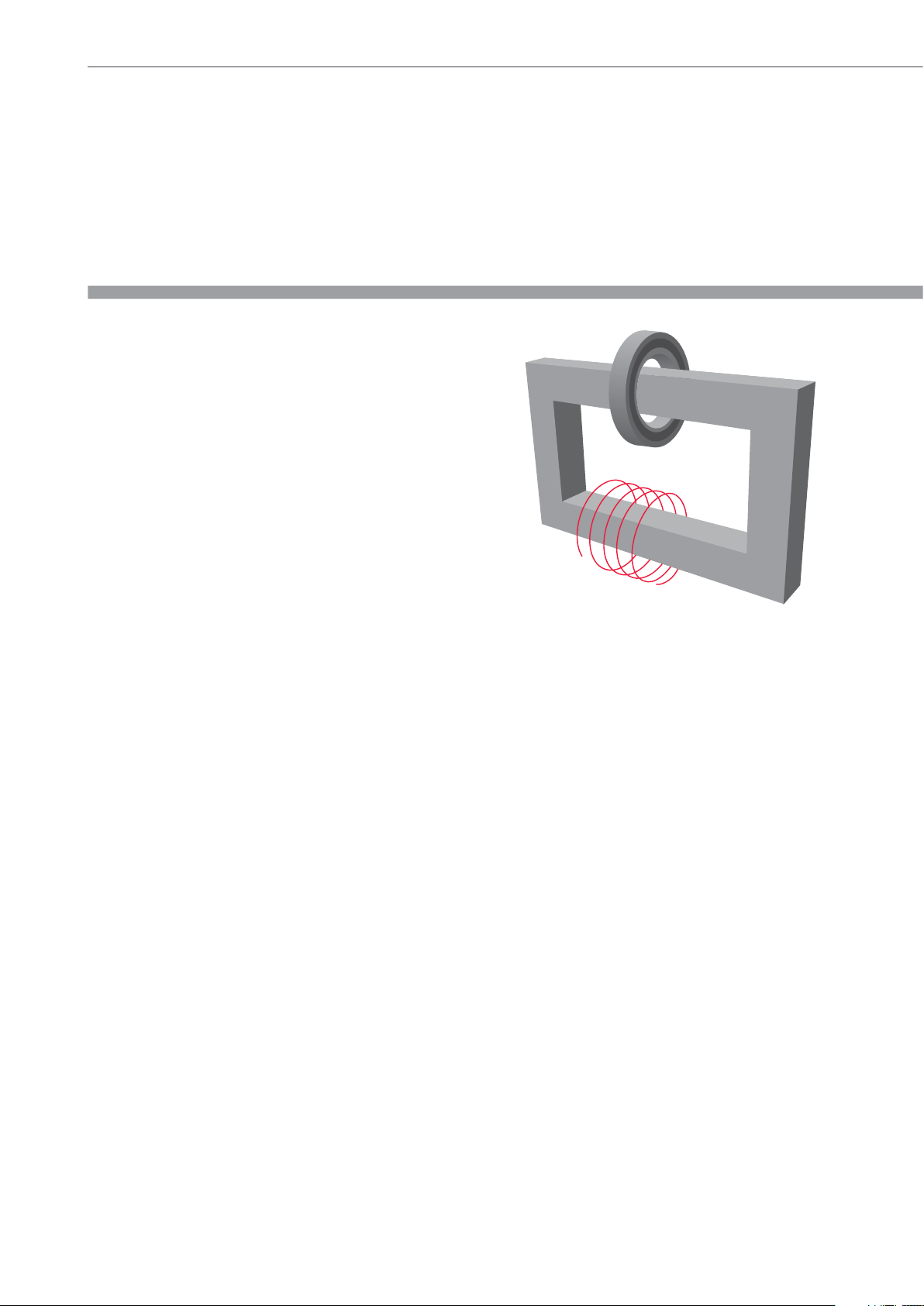
1.2 Principle of Operation
The IHN800 generates heat by means of a large electrical
current that is magnetically induced in the workpiece by
a coil within the heater� The high voltage, low current
electricity flowing through the large number of windings in
the inductive coil induces low voltage, high current electricity
in the workpiece� Because the workpiece has the electrical
characteristics of a coil with a single, short-circuited winding,
the high current generates heat within the workpiece�
Because the heat is generated within the workpiece, all of
the heater components remain cool�
2 Description
The heating cycle is electronically controlled either in a TIME MODE, where the heating time is selected, or in a TEMP MODE
where the desired temperature is selected�
The heater can further be run on 50% capacity when small yokes are used or when there is a risk for too quick heating of
sensitive workpieces (e�g� bearings with C1 or C2 clearance)�
2.1 Components
The induction heater consists of an U-shaped iron core with a large induction coil on one of its legs� The control electronics
sits in a separate control box on top of the heater�
The temperature is controlled by means of a magnetic probe�
4
Page 5

2.2 Technical Data
IHN800
Voltage (± 9%): 3 ~ 400 – 575V / 50 – 60Hz*
Recommended circuit protection 63A circuit breaker
Power consumption (maximum) 24kVA
Temperature control 0 – 250°C (32 – 482°F) in steps of 1°C (2°F)
Probe maximum temperature 250°C (482°F)
Time mode 0 – 60 minutes in steps of 0�1 minute
Power range 50 – 100%
Demagnetisation, automatic Residual magnetism < 2A/cm
Overall dimensions 750 x 400 x 935mm
Area between supports (wxh) 330 x 355mm
Coil diameter 186mm
Weight (with yokes) 300kg
Workpiece maximum weight 1200kg
Maximum heating temperature Approx� 400°C (752°F)
Standard yoke dimensions 100 x 100 x 570mm (for Ø of 142mm)
* Each bearing heater family has several voltage options. Please refer to the type plate on the heater body to determine the actual operating voltage.
3 Installation of Mains Plug
Due to the many types of mains plugs, no mains plug is supplied with the IHN800� A qualified electrician must install a
suitable mains plug� The correct supply voltage is shown on the type plate / underside of the heater�
The wires should be connected as follows:
Color of IHN800 Wire Mains Supply Terminal
Yellow/green Protection earth (PE)
Brown Phase 1 (L1)
Blue Phase 2 (L2)
Connect the IHN800 to only two of the three phases� Verify that the correct circuit breaker is installed� See section 2�2 for
circuit breaker specifications�
5
Page 6

4 Preparation for Use
› Place the IHN800 in the horizontal position on a stable surface�
› Connect the mains plug to a suitable mains supply�
› For workpieces with an internal diameter (>186mm) large enough to fit over the inductive coil, follow these steps:
› Place the workpiece over the inductive coil using appropriate lifting equipment�
› For best performance, adjust the position of the workpiece so that the inductive coil is in the centre�
› Remove the protective film from the bright underside of the sliding yoke before the first use�
› Slide the sliding yoke to the right so that it completely covers the top of both vertical supports�
› For workpieces that do not fit over the inductive coil, these should be heated on the horizontal yoke�
› If you will use TEMP MODE, plug the temperature probe into the connector on the left side of the heater�
Place the magnetic end of the probe on the inner ring of the bearing or on the innermost surface of the workpiece�
› Switch the IHN800 on using the power switch on the left side�
6
Page 7

5 Operation
5.1 Function of Displays
A
B
A) The main display shows the selected time or temperature for heating:
Display Indication
t Time in minutes
°C Temperature in degrees Celsuis
°F Temperature in degrees Fahrenheit
5.2 Function of Buttons
B) The power display shows the selected power setting:
Button Function
POWER Control lamp for main switch on
TIME TIME MODE
TEMP TEMP MODE
BEARING BEARING MODE – recommended heating temperature for bearings of 110°C (230°F) is automatically selected
START/STOP To start and stop heating
ON/OFF Press to start or stop the heater
50% Power reduced to 50%
100% Full capacity
7
Page 8

5.3 Temp Mode
› If the main display shows “t”, press MODE to select TEMP MODE�The main display shows °C or °F in TEMP MODE�
› The selected temperature is shown on the main display� The default temperature for bearings is 110°C (230°F)� If a different
temperature is desired, adjust the temperature on the main display�
› It may be desirable to heat bearings to temperatures above 110°C (230°F) for increased mounting time� Consult the bearing
specifications to determine the maximum permitted temperature� Always ensure the bearing does not lock due to an
excessive expansion of the inner ring compared to outer ring� See section 5�8�
› All Spherical Roller Bearings (SRBs) are subjected to a special heat treatment� These bearings can be operated at temperatures
as high as 200°C (392°F)� Heating these bearings above 110°C (230°F) will not cause any damage as long as the bearing is
still able to rotate� For other bearings, a temperature of 125°C (257°F) must not be exceeded unless otherwise specified�
› Press the 50% key to reduce the POWER to 50%� Use the guidelines in section 5�8 to determine the correct power setting�
› Press START/STOP to start the heater� The main display shows the current temperature of the workpiece�
› When the selected temperature has been reached, the heater demagnetises the workpiece, switches off, and generates an
acoustic signal for 10 seconds or until START/STOP is pressed�
› Press START/STOP to stop the heater�
› Remove the workpiece with proper handling equipment�
› If the workpiece remains on the heater, the heater will start again when the temperature of the workpiece drops 10°C (18°F)�
Press START/STOP to stop the heater and demagnetise the workpiece�
› The IHN800 is now ready to heat another workpiece with the same settings�
5.4 Time Mode
› Select TIME MODE� The main display shows “t” in TIME MODE�
› Set desired heating time by adjusting on the main display�
› Press 50% to reduce the POWER to 50%� Use the guidelines in section 5�8 to determine the correct power setting�
› Press START/STOP to start the heater� The main display shows the time that remains�
8
Page 9

› When the time has elapsed, the heater demagnetises the workpiece, switches off, and generates an acoustic signal
for 10 seconds�
› Press START/STOP to cancel the acoustic signal and stop the heater�
› Remove the workpiece with proper handling equipment�
› The IHN800 is now ready to heat another workpiece with the same settings�
5.5 Temperature Measurement
When the heater is not operating, the temperature of the workpiece can be measured by pressing 0 and TEMP at the same
time� The LED on the START/STOP button flashes during temperature measurement� Press START/STOP to cancel temperature
measurement�
5.6 Change of Temperature Units
Press 0 and BEARING at the same time to switch between °C and °F� The temperature unit setting remains the same even
after disconnection from mains power�
5.7 Demagnetisation
The workpiece is automatically demagnetised when heating is complete� Demagnetisation will not occur if the power is
interrupted or the main switch is switched off� To use the IHN800 for demagnetisation only, select TIME MODE and set the
time to 0�1 minute (6 seconds)�
5.8 Power Level Selection
When heating bearings with an induction heater, most of the heat will be generated in the inner bearing race� The heat will
then be transferred through the bearing� It is therefore important that bearings with small internal clearance or slight preload
are heated slowly� Slow heating ensures that the bearing expands evenly, thereby preventing damage to the bearing�
The shape, weight, size and internal clearances all affect the amount of time required to heat a bearing� The large
variety of bearing types precludes the possibility of providing a specific power level setting for each type� Instead, the
following guidelines are provided:
› For sensitive bearings (including bearings with C1 or C2 internal clearance) or bearings with brass cages and when
using the small yoke, reduce the power to 50%�
9
Page 10

6 Safety Features
The IHN800 is equipped with the following safety features:
› Main switch with overcurrent circuit breaker�
› Automatic overheating protection�
› Automatic current control�
› In the TEMP MODE the heater will switch off if the temperature probe does not register a temperature increase of
1°C (2°F) every 30 seconds� To increase the interval to 60 seconds, press MODE and DOWN at the same time�
7 Troubleshooting
A system fault will be indicated by an acoustic signal and one of the following fault codes on the main display:
Display Fault Action
E00 E Electronic failure Return heater for repair
E01 E Electronic failure Return heater for repair
E02 E Electronic failure Return heater for repair
E03 E Overheated coil Wait until the inductive coil cools
E04 E
E05 E
E06 E Temperature probe not connected (or defective) Check the temperature probe
E07 E Failure during current measurement Return heater for repair
Selected time/temperature
out of range
Temperature increases of less than 1°C (2°F)
every 30 seconds (or 1°C (2°F) every 60 seconds)
Re-program
Check the temperature probe connection� If the connection is
OK, select the 60 second interval as described in section 6 or
operate the heater in TIME MODE�
10
Page 11

8 Spare Parts
Description Part Number
Spare protective gloves IHNGLOVES
Spare temperature probe for IHN800 IHNP1SENSOR
Spare yoke 65 x 65 x 570mm for IHN800 IHN800-Y1
Spare yoke 100 x 100 x 570mm for IHN800 IHN800-Y2
Spare support yoke 100 x 100 x 150mm for IHN800 IHN800-YS1
Spare support yoke 100 x 100 x 370mm for IHN800 IHN800-YS2
11
Page 12

NSK SALES OFFICES WORLDWIDE
HEADQUARTER
Japan
NSK Ltd�-Headquarters
Nissei Bldg�, 1-6-3 Ohsaki
Shinagawa-ku
Tokyo 141-8560
Industrial machinery business
Division-Headquarters
Tel� +81 (3) 3779 7227
Fax +81 (3) 3779 7644
Automotive business
Division-Headquarters
Tel� +81 (3) 3779 7189
Fax +81 (3) 3779 7917
AFRICA
South Africa
NSK South Africa (Pty) Ltd�
27 Galaxy Avenue
Linbro Business Park
Sandton 2146
Tel� +27 (011) 458 3600
Fax +27 (011) 458 3608
nsk-sa@nsk�com
ASIA AND OCEANIA
Australia
NSK Australia Pty� Ltd�
11 Dalmore Drive
Scoresby
Victoria 3179
Tel� +61 3 9765 4400
Fax +61 3 9764 8304
aus-nskenquiries@nsk�com
New Zealand
NSK New Zealand Ltd�
3 Te Apunga Place
Mt� Wellington
Auckland
Tel� +64 9 276 4992
Fax +64 9 276 4082
nz-info@nsk�com
China
NSK Hong Kong Ltd�
Suite 705, 7th FloorSouth Tower
World Finance Centre
Harbour City, T�S�T
Kowloon, Hong Kong
Tel� +852 2739 9933
Fax +852 2739 9323
NSK China Sales Co�, Ltd�
No�8 NSK Rd�, Huaqiao Economic
Development Zone, Kunshan
Jiangsu, China (215332)
Tel� +86 512 5796 3000
Fax +86 512 5796 3300
lndia
NSK in diasales Co�Pvt�Ltd�
6th Floor, Bannari Amman Towers
No�29 Dr� Radhakrishnan Salai
Mylapore, Chennai-600 004 Tamil Nadu
Tel� +91 44 2847 9600
Fax +91 44 2847 9601
lndonesia
Pt� NSK Indonesia
Summitmas II, 6th Floor
Jl� Jend Sudirman Kav� 61-62
Jakarta 12190
Tel� +62 21 252 3458
Fax +62 21 252 3223
Korea
NSK Korea Co�, Ltd�
Posco Center (West Wing) 9F
892, Daechi-4Dong
Kangnam-Ku
Seoul, 135-777
Tel� +82 2 3287 0300
Fax +82 2 3287 0345
Malaysia
NSK Bearings (Malaysia) Sdn� Bhd�
No� 2, Jalan Pemaju, U1/15, Seksyen U1
Hicom Gienmarie lndustrial Park
40150 Shah Alam
Selangor
Tel� +60 3 7803 8859
Fax +60 3 7806 5982
Philippines
NSK Representative Office
8th Floor The Salcedo Towers
169 H�V� dela Costa St�
Salcedo Viilage Makati City
Philippines 1227
Tel� +63 2 893 9543
Fax +63 2 893 9173
Taiwan
Taiwan NSK Precision Co�, Ltd�
11 F�, No�87, Song Jiang Rd�
Jhongshan District
Taipei City 104
Tel� +886 2 2509 3305
Fax +886 2 2509 1393
Thailand
NSK Bearings (Thailand) Co�, Ltd�
26 Soi Onnuch 55/1 Pravet Subdistrict
Pravet District
Bangkok 10250
Tel� +66 2320 2555
Fax +66 2320 2826
Vietnam
NSK Vietnam Co�, Ltd�
Techno Center, Room 204-205
Thang Lang lndustrial Park
Dang Anh District
Hanoi
Tel� +84 4 3955 0159
Fax +84 4 3955 0158
EUROPE
UK
NSK UK Ltd�
Northern Road, Newark
Nottinghamshire NG24 2JF
Tel� +44 (0) 1636 605123
Fax +44 (0) 1636 643276
info-uk@nsk�com
France & Benelux
NSK France S�A�S�
Quartier de l’Europe
2, rue Georges Guynemer
78283 Guyancourt Cedex
Tel� +33 (0) 1 30573939
Fax +33 (0) 1 30570001
info-fr@nsk�com
Germany, Austria,
Switzerland, Nordic
NSK Deutschland GmbH
Harkortstraße 15
40880 Ratingen
Tel� +49 (0) 2102 4810
Fax +49 (0) 2102 4812290
info-de@nsk�com
Italy
NSK Italia S�p�A�
Via Garibaldi, 215
20024 Garbagnate
Milanese (MI)
Tel� +39 02 995 191
Fax +39 02 990 25 778
info-it@nsk�com
Poland & CEE
NSK Polska Sp� z o�o�
Warsaw Branch
Ul� Migdałowa 4/73
02-796 Warszawa
Tel� +48 22 645 15 25
Fax +48 22 645 15 29
info-pl@nsk�com
Russia
NSK Polska Sp� z o�o�
Russian Branch
Office I 703, Bldg 29,
th
18
Line of Vasilievskiy Ostrov,
Saint-Petersburg, 199178
Tel� +7 812 3325071
Fax +7 812 3325072
info-ru@nsk�com
Spain
NSK Spain, S�A�
C/ Tarragona, 161 Cuerpo Bajo
a
2
Planta, 08014 Barcelona
Tel� +34 93 2892763
Fax +34 93 4335776
info-es@nsk�com
Turkey
NSK Rulmanları Orta Doğu Tic� Ltd� Şti
19 Mayıs Mah� Atatürk Cad�
Ulya Engin İş Merkezi No: 68/3 Kat� 6
P�K�: 34736 - Kozyatağı - İstanbul
Tel� +90 216 4777111
Fax +90 216 4777174
turkey@nsk�com
MIDDLE EAST
Dubai
NSK Bearings Gulf Trading Co�
JAFZA View 19, Floor 24 Office 2/3
Jebel Ali Downtown,
PO Box 262163
Dubai, UAE
Tel� +971 (0) 4 804 8205
Fax +971 (0) 4 884 7227
info-me@nsk�com
NORTH AND SOUTH AMERICA
United States of America
NSK Americas, Inc�
4200 Goss Road
Ann Arbor, Michigan 48105
Tel� +1 734 913 7500
Fax +1 734 913 7511
NSK Latin America, Inc�
2500 NW 1 07th Avenue, Suite 300
Miami, Florida 33172
Tel� + 1 305 4 77 0605
Fax + 1 305 4 77 0377
Canada
NSK Canada Inc�
5585 McAdam Road
Mississauga, Ontario
Canada L4Z 1 N4
Tel� + 1 905 890 07 40
Fax + 1 800 800 2788
Argentina
NSK Argentina SRL
Garcia del Rio 2477
Piso 7 Oficina „A“ (1429)
Buenos Aires
Tel� +54 11 4704 51 00
Fax +54 11 4704 0033
Brazil
NSK BRASIL LTDA�
Rua 13 de Maio
1633-14th Andar-Bela Vista-CEP
01327-905 Sao Paulo, SP
Tel� +55 11 3269 4786
Fax +55 11 3269 4720
Peru
NSK PERU S�A�C�
Av� Caminos del lnca 670
Ofic: #402
Santiago del Surco
Lima
Tel� +51 1 652 3372
Fax +51 1 638 0555
Mexico
NSK Rodamientos Mexicana
S�A� DE C�V�
Av� Presidente Juarez No�2007 Lote 5
Col� San Jeronimo Tepetlacalco
Tlalnepantla, Estado de Mexico
C�P �54090
Tel� +52 (55) 3682 2900
Fax +52 (55) 3682 2937
Please also visit our websites:
www.nsk.com | www.au.nsk.com | www.nskeurope.com | www.nskamericas.com
Every care has been taken to ensure the infor mation in this publication is accurate but no liability can be accepted for any errors or omissions�
© Copyright NSK 2015� The contents of this publication are the copyright of the publishers� Printed in Switzerland� Ref: H800/A/E/01�16
 Loading...