

Page 1
USER MANUAL
SUBSCRIBE TO NSK NEWSLETTER
SUBSCRIBE TO NSK NEWSLETTER
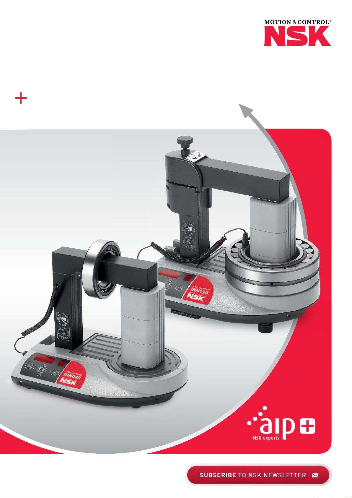
INDUCTION HEATER IHN080/120
Page 2

Table of Contents
Chapter ����������������������������������������������������������������������������������������������������������������������������������������������� Page
Safety Recommendations ������������������������������������������������������������������������������������������������������������������������3
1 Introduction ��������������������������������������������������������������������������������������������������������������������������������������3
1�1 Intended Use ������������������������������������������������������������������������������������������������������������������������������������3
1�2 Principle of Operation ����������������������������������������������������������������������������������������������������������������������4
1�3 Distinguishing Feature ���������������������������������������������������������������������������������������������������������������������4
2 Description ���������������������������������������������������������������������������������������������������������������������������������������4
2�1 Components �������������������������������������������������������������������������������������������������������������������������������������4
2�2 Technical Data ����������������������������������������������������������������������������������������������������������������������������������5
3 Installation of Mains Plug ���������������������������������������������������������������������������������������������������������������5
4 Preparation for Use ��������������������������������������������������������������������������������������������������������������������������6
5 Operation ������������������������������������������������������������������������������������������������������������������������������������������7
5�1 Function of Displays ������������������������������������������������������������������������������������������������������������������������7
5�2 Function of Buttons �������������������������������������������������������������������������������������������������������������������������8
5�3 Temp Mode ��������������������������������������������������������������������������������������������������������������������������������������8
5�4 Time Mode ���������������������������������������������������������������������������������������������������������������������������������������9
5�5 Temperature Measurement ������������������������������������������������������������������������������������������������������������9
5�6 Change of Temperature Unit �����������������������������������������������������������������������������������������������������������9
5�7 Demagnetisation �����������������������������������������������������������������������������������������������������������������������������9
5�8 Power Level Selection ������������������������������������������������������������������������������������������������������������������ 10
6 Safety Features ����������������������������������������������������������������������������������������������������������������������������� 10
7 Troubleshooting ���������������������������������������������������������������������������������������������������������������������������� 11
8 Spare Parts ������������������������������������������������������������������������������������������������������������������������������������ 11
2
Page 3

Safety Recommendations
› Because the IHN080/120 generates a magnetic field,
people wearing a pacemaker must not be within 5 m
(16 ft) of the IHN080/120 during operation� Electronic
equipment, such as wrist watches, may also be affected�
› Follow the operating instructions at all times�
› Be certain that the voltage supply is correct�
› Electrical arcing may occur when a potential difference
exists between the IHN080/120 and the workpiece� This
is not dangerous to human beings and will not cause
damage to the IHN080/120 or the workpiece� However,
the IHN080/120 must never be used in areas where
there is a risk of explosion�
› Do not expose the heater to high humidity�
› Never operate the IHN080/120 without a yoke in
position�
› Do not modify the IHN080/120�
› Use proper handling equipment when lifting heavy
workpieces�
› Avoid contact with hot workpieces� Wear the supplied
heat-resistant gloves to handle hot workpieces�
1 Introduction
The IHN080/120 induction heater is designed to heat bearings that are mounted with an interference fit onto a shaft� The
heat causes the bearing to expand, which eliminates the need to use force during installation� A 90°C (194°F) temperature
difference between the bearing and shaft is generally sufficient to enable installation� At an ambient temperature of 20°C
(68°F), the bearing must therefore be heated to 110°C (230°F)�
1.1 Intended Use
The IHN080/120 has been designed to heat rolling bearings� However, other metal workpieces that form a closed circuit can
also be heated� Examples of acceptable workpieces include bushings, shrink rings, pulleys, and gears� All bearings that fit
over the inductive coil and between the vertical supports with the top yoke in place can be heated using the IHN080/120�
In addition, smaller bearings can be placed over either of the three standard yokes�
3
Page 4
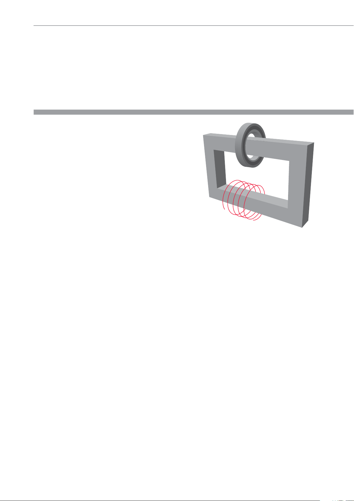
1.2 Principle of Operation
The IHN080/120 generates heat by means of a large electrical
current that is magnetically induced in the workpiece by a
coil within the heater� The high voltage, low current electricity
flowing through the large number of windings in the inductive
coil induces low voltage, high current electricity in the workpiece�
Because the workpiece has the electrical characteristics of a coil
with a single, short-circuited winding, the high current generates
heat within the workpiece� Because the heat is generated within
the workpiece, all of the heater components remain cool�
1.3 Distinguishing Feature
The distinguishing feature of the IHN080/120 induction heater is the location of the workpiece at the same position on the
core as the inductive coil� This design improves efficiency, resulting in less power consumption and faster heating, which
reduces the cost to heat each bearing�
2 Description
The operation of the heater is controlled by the internal electronics in either of two modes� The operator can either select the
desired temperature of the bearing in TEMP MODE or set the length of time that the bearing will be heated in TIME MODE� The
power level can be adjusted in steps of 20% for slower heating of sensitive workpieces (for example, bearings with C1 or C2
clearance)�
2.1 Components
The IHN080/120 induction heater contains a U-shaped iron core with an inductive coil surrounding one of the vertical supports� Internal electronics control the operation of the heater� A removable yoke on the top of the vertical supports allows
the workpiece to be placed onto the heater� The top yoke of the IHN120 is mounted on a swivel� To accommodate smaller
workpieces, two smaller yokes are also provided� A temperature probe is included with the heater� Heat-resistant gloves are
also included�
4
Page 5

2.2 Technical Data
IHN080 IHN0120
Voltage (± 9%): 1 ~ 100 – 240 V / 50-60 Hz* 3 ~ 400 – 575 V / 50-60 Hz*
Recommended circuit protection 20 A circuit breaker 20 A circuit breaker
Power consumption (maximum) 3�7 kVA 9�2 kVA
Temperature control
Probe maximum temperature 250 °C (482 °F) 250 °C (482 °F)
Time mode 0 – 60 minutes in steps of 0�1 minute 0 – 60 minutes in steps of 0�1 minute
Power range 20 – 100% in steps of 20% 20 – 100% in steps of 20%
Demagnetisation, automatic Residual magnetism < 2 A/cm Residual magnetism < 2 A/cm
Overall dimensions 420 x 280 x 345 mm 420 x 280 x 420 mm
Area between supports (wxh) 145 x 205 mm 145 x 205 mm
Coil diameter 115 mm 115 mm
Weight (with yokes) 35 kg 38 kg
Workpiece maximum weight Bearing 80 kg, solid component 40 kg Bearing 120 kg, solid component 60 kg
Maximum heating temperature Approx� 400°C (752°F) Approx� 400 °C (752 °F)
Standard yoke dimensions
0 – 250 °C (32 – 482 °F)
in steps of 1 °C (2 °F)
55 x 55 x 275 mm (for Ø of 80 mm)
28 x 28 x 275 mm (for Ø of 40 mm)
14 x 14 x 275 mm (for Ø of 20 mm)
0 – 250 °C (32 – 482 °F)
in steps of 1 °C (2 °F)
55 x 55 x 275 mm (for Ø of 80 mm)
28 x 28 x 275 mm (for Ø of 40 mm)
14 x 14 x 275 mm (for Ø of 20 mm)
* Each bearing heater family has several voltage options. Please refer to the type plate on the heater body to determine the actual operating voltage.
3 Installation of Mains Plug
Due to the many types of mains plugs, no mains plug is supplied with the IHN080/120� A qualified electrician must install a
suitable mains plug� The correct supply voltage is shown on the type plate / underside of the heater�
The wires should be connected as follows:
IHN080
Color of IHN080 Wire Mains Supply Terminal
Yellow/green Protection earth (PE)
Brown Phase 1 (L1)
Blue Neutral (N)
5
Page 6

IHN120
Color of IHN120 Wire Mains Supply Terminal
Yellow/green Protection earth (PE)
Brown Phase 1 (L1)
Blue Phase 2 (L2)
Connect the IHN120 to only two of the three phases� Verify that the correct circuit breaker is installed� See section 2�2 for
circuit breaker specifications�
4 Preparation for Use
› Place the IHN080/120 in the horizontal position on a stable surface�
› Connect the mains plug to a suitable mains supply�
› For the IHN120 only, follow these steps to install the swivel arm:
› Attach the protection plate (4) to the side post to prevent damage�
› Install the swivel head (1) and the swivel body (2) on the lefthand
side post of the heater�
› Install the large top yoke (55 x 55mm) in the swivel head� Adjust
the swivel body so that there is no visible gap (A) between the
side post and the yoke�
› Tighten the four screws (3) of the swivel body (maximum torque 5Nm)�
› Turn the screw (5) on top of the swivel head to position the top
yoke� The top yoke must contact as much of the upper surface of
the right-hand side post (B) as possible� Noise during
operation could indicate that the top yoke is not positioned properly�
› Special notes for the IHN120:
› The yoke support is required when either of the smaller yokes
(28 x 28mm or 14 x 14mm) is installed� Install the yoke support and
the yoke together in the swivel head� If necessary, rotate the swivel
head to provide better access�
› Heavy workpieces (≥10kg / 22lbs) that must be installed on the top
yoke should be supported until the yoke is in the correct position on
the right-hand side post� The heater may tip over if the workpiece is not supported�
› The swivel body (2) can remain on the heater at all times�
› Turn the screw (5) on top of the swivel head to position the top yoke� The top yoke must contact as much of the upper
surface of the right-hand side post (B) as possible� Noise during operation could indicate that the top yoke is not positioned
properly�
6
Page 7

› For workpieces with an internal diameter large enough to fit over the inductive coil, follow these steps:
› Place the workpiece over the inductive coil using appropriate lifting equipment�
› For best performance, adjust the position of the workpiece so that the inductive coil is in the center�
› Remove the protective film from the bright underside of the top yoke before the first use�
› Position the top yoke so that it completely covers the top of both vertical supports�
› If you will use TEMP MODE, plug the temperature probe into the connector on the left side of the heater� Place the magnetic
end of the probe on the inner ring of the bearing or on the innermost surface of the workpiece�
› Use the power switch on the left side to switch on the IHN080/120�
› Observe the self-test of the display and signal tone�
5 Operation
5.1 Function of Displays
A
B
A) The main display shows the selected time or temperature for heating:
Display Indication
t Time in minutes
°C Temperature in degrees Celsuis
°F Temperature in degrees Fahrenheit
B) The power display shows the selected power setting:
Display Indication
•
••
•••
••••
•••••
20% power
40% power
60% power
80% power
100% power
7
Page 8

5.2 Function of Buttons
Button Function
POWER Press to adjust the power in steps of 20%� The selected power is indicated on the power display�
MODE Press to switch between TIME MODE and TEMP MODE�
UP (+) Press to increase the value shown on the main display�
DOWN (-) Press to decrease the value shown on the main display�
START/STOP
Press to start or stop the heater� The LED on the START/STOP button is lit when the heater is heating and
flashes during temperature measurement�
5.3 Temp Mode
› If the main display shows “t”, press MODE to select TEMP MODE� The main display shows °C or °F in TEMP MODE�
› The selected temperature is shown on the main display� The default temperature for bearings is 110°C (230°F)� If a different
temperature is desired, press UP or DOWN to adjust the temperature in steps of 1°C (2°F)�
› It may be desirable to heat bearings to temperatures above 110°C (230°F) for increased mounting time� Consult the bearing
specifications to determine the maximum permitted temperature� Always ensure the bearing does not lock due to an
excessive expansion of the inner ring compared to outer ring� See section 5�8�
› All Spherical Roller Bearings (SRBs) are subjected to a special heat treatment� These bearings can be operated at temperatures
as high as 200°C (392°F)� Heating these bearings above 110°C (230°F) will not cause any damage as long as the bearing is
still able to rotate� For other bearings, a temperature of 125°C (257°F) must not be exceeded unless otherwise specified�
› Press POWER to select the power level� Use the guidelines in section 5�8 to determine the correct power setting�
› Make sure the temperature probe is mounted on the bearing inner ring�
› Press START/STOP to start the heater� The main display shows the current temperature of the workpiece�
› When the selected temperature has been reached, the heater demagnetises the workpiece, switches off and generates an
acoustic signal for 10 seconds or until START/STOP is pressed�
› Press START/STOP to stop the heater�
› Remove the workpiece with proper handling equipment�
8
Page 9

› If the workpiece remains on the heater, the heater will start again when the temperature of the workpiece drops 10°C (18°F)�
Press START/STOP to stop the heater and demagnetise the workpiece�
› The IHN080/120 is now ready to heat another workpiece with the same settings�
5.4 Time Mode
› If the main display shows °C or °F, press MODE to select TIME MODE� The main display shows “t” in TIME MODE�
› Press UP or DOWN to adjust the time in steps of 0�1 minute�
› Press POWER to select the power level� Use the guidelines in section 5�8 to determine the correct power setting�
› Press START/STOP to start the heater� The main display shows the time that remains�
› When the time has elapsed, the heater demagnetises the workpiece, switches off and generates an acoustic signal for 10 seconds�
› Press START/STOP to cancel the acoustic signal and stop the heater�
› Remove the workpiece with proper handling equipment�
› The IHN080/120 is now ready to heat another workpiece with the same settings�
5.5 Temperature Measurement
When the heater is not operating, the temperature of the workpiece can be measured by pressing MODE and START/STOP
at the same time� The LED on the START/STOP button flashes during temperature measurement� Press START/STOP to cancel
temperature measurement�
5.6 Change of Temperature Units
Press MODE and UP at the same time to switch between °C and °F� The temperature unit setting remains the same even after
disconnection from mains power�
5.7 Demagnetisation
The workpiece is automatically demagnetised when heating is complete� Demagnetisation will not occur if the power is
interrupted or the main switch is switched off� To use the IHN080/120 for demagnetisation only, select TIME MODE and set
the time to 0�1 minute (6 seconds)�
9
Page 10

5.8 Power Level Selection
When heating bearings with an induction heater, most of the heat will be generated in the inner bearing race� The heat
will then be transferred through the bearing� It is therefore important that bearings with small internal clearance or slight
preload are heated slowly� Slow heating ensures that the bearing expands evenly, thereby preventing damage to the bearing�
The shape, weight, size, and internal clearances all affect the amount of time required to heat a bearing� The large
variety of bearing types prevents the possibility of providing a specific power level setting for each type� Instead, the
following guidelines are provided:
› For sensitive bearings (including bearings with C1 or C2 internal clearance) or bearings with brass cages, do not exceed
20% power when using the small yoke, 40% power when using the medium yoke, or 60% power when using the
large yoke�
› When using the small yoke, never exceed 40% power�
› When using the medium yoke, never exceed 60% power�
6 Safety Features
The IHN080/120 is equipped with the following safety features:
› Automatic overheating protection�
› Automatic current control�
› In the TEMP MODE the heater will switch off if the temperature probe does not register a temperature increase of 1°C (2°F)
every 15 seconds� To increase the interval to 30 seconds, press MODE and DOWN at the same time�
› Additionally, the IHN120 is equipped with a main switch with over-current circuit breaker�
10
Page 11

7 Troubleshooting
A system fault will be indicated by an acoustic signal and one of the following fault codes on the main display:
Display Fault Action
E01 E General system failure Return heater for repair
E02 E Memory failure Return heater for repair
E03 E Overheated coil Wait until the inductive coil cools
E04 E Not in use
E05 E
E06 E Temperature probe not connected (or defective) Check the temperature probe
E07 E Failure during current measurement Return heater for repair
E08 E
E09 E Overheated printed circuit board Wait until the printed circuit board cools�
Temperature increase of less than 1°C (2°F) every
15 seconds (or 1°C (2°F) every 30 seconds)
Failure during communication with power printed
circuit board
Check the temperature probe connection� If the connection
is OK, select the 30 second interval as described in section 6
or operate the heater in TIME MODE�
Return heater for repair
8 Spare Parts
Description Part Number
Spare temperature probe IHNP2SENSOR
Spare protective gloves IHNGLOVES
Spare set support yoke 55 x 55 x 100 mm for IHN080/120 IHN080/120-YS
Spare yoke 10 x 10 x 275 mm for IHN080/120 IHN080/120-Y1
Spare yoke 14 x 14 x 275 mm for IHN080/120 IHN080/120-Y2
Spare yoke 20 x 20 x 275 mm for IHN080/120 IHN080/120-Y3
Spare yoke 28 x 28 x 275 mm for IHN080/120 IHN080/120-Y4
Spare yoke 40 x 40 x 275 mm for IHN080/120 IHN080/120-Y6
Spare yoke 55 x 55 x 275 mm for IHN080/120 IHN080/120-Y8
Spare swivel arm complete for IHN080/120 IHN080/120-SA
11
Page 12

NSK SALES OFFICES WORLDWIDE
HEADQUARTER
Japan
NSK Ltd�-Headquarters
Nissei Bldg�, 1-6-3 Ohsaki
Shinagawa-ku
Tokyo 141-8560
Industrial machinery business
Division-Headquarters
Tel� +81 (3) 3779 7227
Fax +81 (3) 3779 7644
Automotive business
Division-Headquarters
Tel� +81 (3) 3779 7189
Fax +81 (3) 3779 7917
AFRICA
South Africa
NSK South Africa (Pty) Ltd�
27 Galaxy Avenue
Linbro Business Park
Sandton 2146
Tel� +27 (011) 458 3600
Fax +27 (011) 458 3608
nsk-sa@nsk�com
ASIA AND OCEANIA
Australia
NSK Australia Pty� Ltd�
11 Dalmore Drive
Scoresby
Victoria 3179
Tel� +61 3 9765 4400
Fax +61 3 9764 8304
aus-nskenquiries@nsk�com
New Zealand
NSK New Zealand Ltd�
3 Te Apunga Place
Mt� Wellington
Auckland
Tel� +64 9 276 4992
Fax +64 9 276 4082
nz-info@nsk�com
China
NSK Hong Kong Ltd�
Suite 705, 7th FloorSouth Tower
World Finance Centre
Harbour City, T�S�T
Kowloon, Hong Kong
Tel� +852 2739 9933
Fax +852 2739 9323
NSK China Sales Co�, Ltd�
No�8 NSK Rd�, Huaqiao Economic
Development Zone, Kunshan
Jiangsu, China (215332)
Tel� +86 512 5796 3000
Fax +86 512 5796 3300
lndia
NSK in diasales Co�Pvt�Ltd�
6th Floor, Bannari Amman Towers
No�29 Dr� Radhakrishnan Salai
Mylapore, Chennai-600 004 Tamil Nadu
Tel� +91 44 2847 9600
Fax +91 44 2847 9601
lndonesia
Pt� NSK Indonesia
Summitmas II, 6th Floor
Jl� Jend Sudirman Kav� 61-62
Jakarta 12190
Tel� +62 21 252 3458
Fax +62 21 252 3223
Korea
NSK Korea Co�, Ltd�
Posco Center (West Wing) 9F
892, Daechi-4Dong
Kangnam-Ku
Seoul, 135-777
Tel� +82 2 3287 0300
Fax +82 2 3287 0345
Malaysia
NSK Bearings (Malaysia) Sdn� Bhd�
No� 2, Jalan Pemaju, U1/15, Seksyen U1
Hicom Gienmarie lndustrial Park
40150 Shah Alam
Selangor
Tel� +60 3 7803 8859
Fax +60 3 7806 5982
Philippines
NSK Representative Office
8th Floor The Salcedo Towers
169 H�V� dela Costa St�
Salcedo Viilage Makati City
Philippines 1227
Tel� +63 2 893 9543
Fax +63 2 893 9173
Taiwan
Taiwan NSK Precision Co�, Ltd�
11 F�, No�87, Song Jiang Rd�
Jhongshan District
Taipei City 104
Tel� +886 2 2509 3305
Fax +886 2 2509 1393
Thailand
NSK Bearings (Thailand) Co�, Ltd�
26 Soi Onnuch 55/1 Pravet Subdistrict
Pravet District
Bangkok 10250
Tel� +66 2320 2555
Fax +66 2320 2826
Vietnam
NSK Vietnam Co�, Ltd�
Techno Center, Room 204-205
Thang Lang lndustrial Park
Dang Anh District
Hanoi
Tel� +84 4 3955 0159
Fax +84 4 3955 0158
EUROPE
UK
NSK UK Ltd�
Northern Road, Newark
Nottinghamshire NG24 2JF
Tel� +44 (0) 1636 605123
Fax +44 (0) 1636 643276
info-uk@nsk�com
France & Benelux
NSK France S�A�S�
Quartier de l’Europe
2, rue Georges Guynemer
78283 Guyancourt Cedex
Tel� +33 (0) 1 30573939
Fax +33 (0) 1 30570001
info-fr@nsk�com
Germany, Austria,
Switzerland, Nordic
NSK Deutschland GmbH
Harkortstraße 15
40880 Ratingen
Tel� +49 (0) 2102 4810
Fax +49 (0) 2102 4812290
info-de@nsk�com
Italy
NSK Italia S�p�A�
Via Garibaldi, 215
20024 Garbagnate
Milanese (MI)
Tel� +39 02 995 191
Fax +39 02 990 25 778
info-it@nsk�com
Poland & CEE
NSK Polska Sp� z o�o�
Warsaw Branch
Ul� Migdałowa 4/73
02-796 Warszawa
Tel� +48 22 645 15 25
Fax +48 22 645 15 29
info-pl@nsk�com
Russia
NSK Polska Sp� z o�o�
Russian Branch
Office I 703, Bldg 29,
th
18
Line of Vasilievskiy Ostrov,
Saint-Petersburg, 199178
Tel� +7 812 3325071
Fax +7 812 3325072
info-ru@nsk�com
Spain
NSK Spain, S�A�
C/ Tarragona, 161 Cuerpo Bajo
a
2
Planta, 08014 Barcelona
Tel� +34 93 2892763
Fax +34 93 4335776
info-es@nsk�com
Turkey
NSK Rulmanları Orta Doğu Tic� Ltd� Şti
19 Mayıs Mah� Atatürk Cad�
Ulya Engin İş Merkezi No: 68/3 Kat� 6
P�K�: 34736 - Kozyatağı - İstanbul
Tel� +90 216 4777111
Fax +90 216 4777174
turkey@nsk�com
MIDDLE EAST
Dubai
NSK Bearings Gulf Trading Co�
JAFZA View 19, Floor 24 Office 2/3
Jebel Ali Downtown,
PO Box 262163
Dubai, UAE
Tel� +971 (0) 4 804 8205
Fax +971 (0) 4 884 7227
info-me@nsk�com
NORTH AND SOUTH AMERICA
United States of America
NSK Americas, Inc�
4200 Goss Road
Ann Arbor, Michigan 48105
Tel� +1 734 913 7500
Fax +1 734 913 7511
NSK Latin America, Inc�
2500 NW 1 07th Avenue, Suite 300
Miami, Florida 33172
Tel� + 1 305 4 77 0605
Fax + 1 305 4 77 0377
Canada
NSK Canada Inc�
5585 McAdam Road
Mississauga, Ontario
Canada L4Z 1 N4
Tel� + 1 905 890 07 40
Fax + 1 800 800 2788
Argentina
NSK Argentina SRL
Garcia del Rio 2477
Piso 7 Oficina „A“ (1429)
Buenos Aires
Tel� +54 11 4704 51 00
Fax +54 11 4704 0033
Brazil
NSK BRASIL LTDA�
Rua 13 de Maio
1633-14th Andar-Bela Vista-CEP
01327-905 Sao Paulo, SP
Tel� +55 11 3269 4786
Fax +55 11 3269 4720
Peru
NSK PERU S�A�C�
Av� Caminos del lnca 670
Ofic: #402
Santiago del Surco
Lima
Tel� +51 1 652 3372
Fax +51 1 638 0555
Mexico
NSK Rodamientos Mexicana
S�A� DE C�V�
Av� Presidente Juarez No�2007 Lote 5
Col� San Jeronimo Tepetlacalco
Tlalnepantla, Estado de Mexico
C�P �54090
Tel� +52 (55) 3682 2900
Fax +52 (55) 3682 2937
Please also visit our websites:
www.nsk.com | www.au.nsk.com | www.nskeurope.com | www.nskamericas.com
Every care has been taken to ensure the infor mation in this publication is accurate but no liability can be accepted for any errors or omissions�
© Copyright NSK 2015� The contents of this publication are the copyright of the publishers� Printed in Switzerland� Ref: H080/A/E/01�16
 Loading...