

Page 1
USER MANUAL
SUBSCRIBE TO NSK NEWSLETTER
SUBSCRIBE TO NSK NEWSLETTER
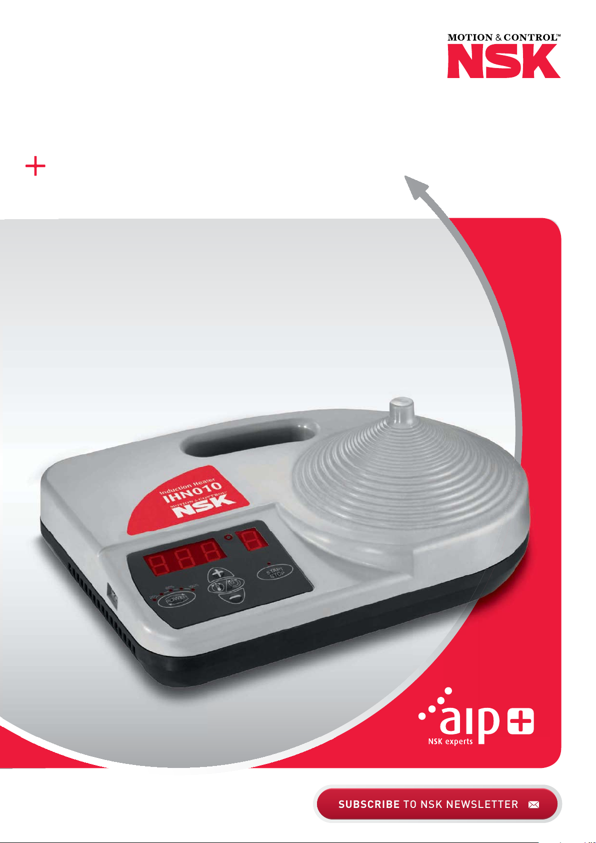
INDUCTION HEATER IHN010
Page 2

Table of Contents
Chapter ����������������������������������������������������������������������������������������������������������������������������������������������� Page
Safety Recommendations ������������������������������������������������������������������������������������������������������������������������3
1 Introduction ��������������������������������������������������������������������������������������������������������������������������������������3
1�1 Intended Use ������������������������������������������������������������������������������������������������������������������������������������3
1�2 Principle of Operation ����������������������������������������������������������������������������������������������������������������������4
1�3 Distinguishing Feature ���������������������������������������������������������������������������������������������������������������������4
2 Description ���������������������������������������������������������������������������������������������������������������������������������������4
2�1 Components �������������������������������������������������������������������������������������������������������������������������������������4
2�2 Technical Data ����������������������������������������������������������������������������������������������������������������������������������5
3 Preparation for Use ��������������������������������������������������������������������������������������������������������������������������6
4 Operation ������������������������������������������������������������������������������������������������������������������������������������������6
4�1 Function of Displays ������������������������������������������������������������������������������������������������������������������������7
4�2 Function of Buttons �������������������������������������������������������������������������������������������������������������������������7
4�3 Temp Mode ��������������������������������������������������������������������������������������������������������������������������������������7
4�4 Time Mode ���������������������������������������������������������������������������������������������������������������������������������������8
4�5 Temperature Measurement ������������������������������������������������������������������������������������������������������������9
4�6 Change of Temperature Unit �����������������������������������������������������������������������������������������������������������9
4�7 Demagnetisation �����������������������������������������������������������������������������������������������������������������������������9
4�8 Power Level Selection ���������������������������������������������������������������������������������������������������������������������9
5 Safety Features ����������������������������������������������������������������������������������������������������������������������������� 10
6 Electromagnetic Field and Personal Safety �������������������������������������������������������������������������������� 10
7 Troubleshooting ���������������������������������������������������������������������������������������������������������������������������� 11
8 Spare Parts ������������������������������������������������������������������������������������������������������������������������������������ 11
2
Page 3

Safety Recommendations
› The operating instructions must be followed and kept in
a safe place at all times�
› The IHN010 device generates a magnetic field� People
wearing a pacemaker, especially if it is an older model,
should consult their doctor before operating the device
as it could impair the functioning of the pacemaker�
Electronic equipment such as wrist watches, memory
cards, monitors and displays, magnetic tapes, etc� may
also be affected�
› Always place the device on a non-metallic surface that is
stable and dry�
› Ensure that the ventilation slots are free at all times and
the device can draw in cold air through its base�
› The device must always be connected to an AC power
network with the correct voltage as indicated on the
type plate�
› Ensure that the device does not get wet and do not
expose it to high humidity levels�
› The device must not be immersed in water or any other
liquid�
› Do not operate the device in the vicinity of heat sources
and ensure that it is placed a sufficient distance away
from walls and flammable objects�
› The device must not be used in areas where there is a
risk of explosion�
› Do not activate the heating process if no rolling bearing
or other workpiece is in place�
› Avoid contact with hot workpieces� Wear the supplied
protective gloves when handling hot workpieces�
› Please ensure that you always use a power and
temperature level that is appropriate for the workpiece
in question to ensure that it is heated carefully and not
damaged�
› The device is intended for heating rolling bearings� The
manufacturer accepts no liability in the event of
inappropriate or incorrect usage�
› Regularly check the plug, connecting cable and heating
cone for wear and tear or damage� If you discover any
damage, send the device to your NSK partner for
inspection�
› Do not modify the device�
1 Introduction
The IHN010 induction heater is designed for heating rolling bearings and other ferritic, circular workpieces� The heat causes
the workpiece to expand, which eliminates the need to use force during installation� A 90°C (194°F) temperature difference
between the bearing and shaft is sufficient to enable easy installation� At an ambient temperature of 20°C (68°F), the bearing
must therefore be heated to 110°C (230°F)�
1.1 Intended Use
The IHN010 portable induction heater has been designed to heat rolling bearings� Examples of acceptable workpieces include
bushings, shrink rings, pulleys, rings, etc� The IHN010 portable induction heater is primarily intended for on-site repairs and
rolling bearing replacements by service and maintenance staff�
3
Page 4

1.2 Principle of Operation
The IHN010 generates a magnetic field in the medium
frequency range (approx� 25kHz), similar to an inductive hot
plate� The magnetic field induces a voltage targeted on the
inner ring of the workpiece� This creates eddy currents, which
efficiently heat the workpiece� As the heat in the workpiece is
generated by the current flow, all other parts of the induction
heater remain cold� The heating process is based on the principle of eddy currents, so the workpieces to be heated should
be composed of ferritic (magnetic) metals� In case of doubt,
simply check the workpiece using the magnet of the temperature probe� This patented heating method enables fast, easy
and energy efficient heating of workpieces�
1.3 Distinguishing Feature
The distinguishing feature of the IHN010 induction heater is the fact that the workpiece can only be placed on the cone-shaped
workpiece support for heating� The energy transfer is contact-free, and is generated via the medium-frequency coil situated below� The cone-shaped workpiece support creates an optimal magnetic field distribution in the rings of the rolling bearing, thereby
ensuring that heat is distributed homogenously� This design improves efficiency, resulting in lower power consumption and faster
heating, which significantly reduces the costs of heating the bearings� This special technology allows the device to be very light
weight and portable� In addition, the device is fitted with predictive temperature control (PTC)� For every heating process, the
temperature increase curve of the workpiece/rolling bearing is measured constantly, thereby opti mising the heating performance� This ensures that the target temperature is achieved quickly without overheating the rolling bearing�
2 Description
The operation of the heater is controlled by the internal electronics in either of two modes� The operator can either select the desired temperature of the bearing in TEMP MODE or set the length of time that the bearing will be heated in TIME MODE� The power
level can be adjusted in steps of 20% for slower heating of sensitive workpieces (for example, bearings with C1 or C2 clearance)�
2.1 Components
The IHN010 induction heater is comprised of a portable housing with integrated operating electronics and cone-shaped
workpiece support� A temperature probe can be attached for measuring and monitoring the temperature of the workpiece�
The mains cable is enclosed separately, as are protective gloves for safe handling of hot workpieces� All of the equipment
can be stored in the practical carrying case�
4
Page 5

2.2 Technical Data
IHN010
Voltage (± 9%): 1 ~ 110 – 240V / 50 – 60Hz*
Recommended circuit protection 10�5A circuit breaker (240V)
6�5A circuit breaker (110 – 115V)
Power consumption (maximum) 1�5kVA
Temperature control 20 – 180°C, in steps of 1°C
68 – 356°F, in steps of 2°F
Temperature probe K-type thermocouple with magnetic bracket
Power range 20 – 100%, in steps of 20%
Time mode 0 – 10 minutes, in steps of 0�1 minutes
Operating modes Automatic temperature or time mode
Demagnetisation, automatic Residual magnetism < 2A/cm
Overall dimensions 340 x 250 x 64mm (over cone 121mm)
Weight 3�5kg
Workpiece:
Inner diameter
Width
External diameter
20mm and above
Up to 60mm
Up to 160mm
Workpiece maximum weight Up to 10kg
Workpiece materials Ferritic metals (magnetic)
Maximum heating temperature < 180°C / 356°F
Authorisations, inspections CE
* Each bearing heater family has several voltage options� Please refer to the type plate on the heater body to determine the actual operating voltage�
5
Page 6

3 Preparation for Use
› Place the device horizontally on a stable, non-metallic surface�
› Ensure that the device’s ventilation slots are free at all times and that it can draw in cold air through its base�
› Connect the mains plug to a suitable power supply�
› The rolling bearing to be heated is placed horizontally in the centre of the IHN010 induction heater’s step-shaped support cone�
› If you are going to operate the device in TEMP MODE, connect the temperature probe with the helix cable to the left side of
the device� Make sure the polarity of the plug is correct�
› Use the holding magnets in the measuring head of the temperature probe as a quick and easy way of checking whether the
workpiece is made of ferritic metal (magnetic) and therefore can be heated optimally using the IHN010 induction heater�
› The magnetic measuring head of the temperature probe is placed on the inner ring of the rolling bearing or the innermost
point of the ring� The temperature probe is only used in TEMP MODE� When heating a workpiece in TIME MODE, the probe is
not required and does not need to be connected�
4 Operation
4.1 Function of Displays
A) The main display shows the selected heating time or heating temperature:
Display Indication
t Time in minutes
°C Temperature in degrees Celsuis
°F Temperature in degrees Fahrenheit
6
A
B
Page 7

B) The power display shows the selected power setting:
Display Indication
•
••
•••
••••
•••••
4.2 Function of Buttons
Button Function
POWER Press to adjust the power in steps of 20%� The selected power is indicated on the power display�
MODE Press to switch between TIME MODE and TEMP MODE�
UP (+) Press to increase the value shown on the main display�
DOWN (-) Press to decrease the value shown on the main display�
START/STOP
20% power
40% power
60% power
80% power
100% power
Press to start or stop the heater� The LED on the START/STOP button is lit when the heater is heating and
flashes during temperature measurement�
4.3 Temp Mode
› If the main display shows “t”, press MODE to select TEMP MODE� The main display shows °C or °F in TEMP MODE�
› The selected temperature is shown on the main display� The default temperature for bearings is 110°C (230°F)�
If a different temperature is desired, press UP or DOWN to adjust the temperature in steps of 1°C (2°F)�
› It may be desirable to heat bearings to temperatures above 110°C (230°F) for increased mounting time� To determine the
maximum permitted temperature, consult the specifications of the bearing manufacturer� Always ensure the bearing does not
lock due to an excessive expansion of the inner ring compared to the outer ring� See section 4�8�
› All Spherical Rolling Bearings (SRBs) are subjected to a special heat treatment� These bearings can be operated at temperatures
as high as 200°C (392°F)� Heating these bearings above 110°C (230°F) will not cause any damage as long as the bearing is
still able to rotate� For other bearings, a temperature of 125°C (257°F) must not be exceeded unless otherwise specified�
› Press POWER to select the power level� Use the guidelines in section 4�8 to determine the correct power setting�
› Press START/STOP to start the heater� The main display shows the current temperature of the workpiece�
7
Page 8

› When the selected temperature has been reached, the heater demagnetises the workpiece, switches off, and generates
an acoustic signal for 10 seconds or until START/STOP is pressed�
› Press START/STOP to stop the heater�
› Always wear protective gloves and other appropriate protective equipment when removing the hot workpiece� NB: Risk of
burning� The workpiece may also be removed using suitable handling equipment�
› If the workpiece remains on the heater, the heater will start again when the temperature of the workpiece drops 10°C (18°F)�
Press START/STOP to stop the heater and demagnetise the workpiece�
› The device is now ready to heat another workpiece with the same settings�
4.4 Time Mode
› If the main display shows °C or °F, press MODE to select TIME MODE� The main display shows “t” in TIME MODE�
› Press UP or DOWN to adjust the time in steps of 0�1 minute�
› Press POWER to select the power level� Use the guidelines in section 4�8 to determine the correct power setting�
› Press START/STOP to start the heater� The main display shows the time that remains�
› When the time has elapsed, the heater demagnetises the workpiece, switches off, and generates an acoustic signal for
10 seconds�
› Press START/STOP to turn the induction heater off�
› Always wear protective gloves and other appropriate protective equipment when removing the hot workpiece� NB: Risk of
burning� The workpiece may also be removed using suitable handling equipment�
› Remove the workpiece using proper handling equipment�
› The device is now ready to heat the next workpiece with the same settings�
8
Page 9

4.5 Temperature Measurement
When the heater is not operating, the temperature of the workpiece can be measured by pressing MODE and START/STOP
at the same time� The LED on the START/STOP button flashes during temperature measurement� Press START/STOP to cancel
temperature measurement�
4.6 Change of Temperature Units
Press MODE and UP at the same time to switch between °C and °F� The temperature unit setting remains the same even after
disconnection from mains power�
4.7 Demagnetisation
According to the eddy current principle, the work piece is automatically demagnetised at the end of the heating cycle�
4.8 Power Level Selection
When heating bearings with the IHN010, it is important that bearings with small internal clearance or slight preload are
heated slowly� Slow heating ensures that the bearing expands slowly, thereby preventing damage to the bearing� In
addition, it is possible that the ferrite cage and seals could be heated more quickly than the inner-ring, due to their low mass�
The shape, weight, size, and internal clearances all affect the amount of time required to heat a bearing� The large
variety of bearing types precludes the possibility of providing a specific power level setting for each type� Instead, the
following guide lines are provided:
For sensitive bearings (little internal clearance) the power must be reduced�
› Max� 20% for small bearings (positioned around the tip of the cone)
› Max� 40% for medium-sized bearings (positioned in the centre of the cone)
› Max� 60% for large bearings (positioned at the bottom of the cone)
9
Page 10

For bearings with a steel cage or with seals, the power must be reduced�
The following table shows what power level to be selected�
Bearing Cage Shield Power Max.Temp.
Deep groove ball
bearings
Other
bearings
If the bearings are sealed on one side only, they must be placed on the device with the seal facing upwards�
In this arrangement, the power level of 100% can be selected�
Steel Steel 20% 110°C / 230°F
Steel Plastic 20% 100°C / 212°F
Steel None 100% 110°C / 230°F
Steel Steel 20% 110°C / 230°F
Brass Steel 20% 110°C / 230°F
Plastic Steel 20% 110°C / 230°F
Steel Plastic 20% 100°C / 212°F
Brass Plastic 20% 100°C / 212°F
Plastic Plastic 20% 100°C / 212°F
Steel None 100% 110°C / 230°F
Brass None 100% 110°C / 230°F
Plastic None 100% 110°C / 230°F
5 Safety Features
The IHN010 device is equipped with the following safety features:
› Power switch�
› Internal safety fuse for power electronics�
› Automatic overheating protection for the circuit breaker�
› Automatic current control for intermediate circuit and coil electricity�
› Automatic detection and power reduction if no workpiece is in place for heating�
› In the TEMP MODE the heater will switch off if the temperature probe does not register a temperature increase of 1°C (2°F)
every 15 seconds� To increase the interval to 30 seconds, press MODE and DOWN at the same time�
10
Page 11

6 Electromagnetic Field and Personal Safety
During the heating function, the IHN010 unit generates a maximum magnetic flux density of less than 5�7µT at a distance
of half a meter away� The device is therefore within the range that applies to the household sector for induction cooktops�
Modern pacemakers are protected from such interference� Nevertheless, the manufacturers recommend that those using
pacemakers remain a minimum distance of 40cm from the induction heater� People with cardiac pacemakers should check
with their doctor about possible disrupting effects�
7 Troubleshooting
A system fault will be indicated by an acoustic signal and one of the following fault codes on the main display:
Display Fault Action
E01 E General system failure Return heater for repair
E02 E Memory failure Return heater for repair
E03 E Overheated coil Wait until the inductive coil cools
E04 E No workpiece in place Place workpiece on device
Temperature increase of less than 1°C (2°F) every
E05 E
E06 E Temperature probe not connected (or defective) Check the temperature probe
E07 E Failure during current measurement Return heater for repair
E08 E
E09 E Overheated printed circuit board
E10 E Grid undervoltage detected
15 seconds (or 1°C (2°F) every 30 seconds)
Failure during communication with power printed
circuit board
Check the temperature probe connection� If the connection
is OK, select the 30 second interval as described in section
5 or operate the heater in TIME MODE�
Return heater for repair
Wait until the printed circuit board cools� Alternatively,
the PCB temperature will be displayed� The device can be
re-started at a temperature below 40°C (displayed as <40)�
Connect the device to another socket or
shorten the extension cord�
8 Spare Parts
Description Part Number
Spare temperature probe IHNP2SENSOR
Spare protective gloves IHNGLOVES
Spare portable soft case for IHN010 IHN025-B
11
Page 12

NSK SALES OFFICES WORLDWIDE
HEADQUARTER
Japan
NSK Ltd�-Headquarters
Nissei Bldg�, 1-6-3 Ohsaki
Shinagawa-ku
Tokyo 141-8560
Industrial machinery business
Division-Headquarters
Tel� +81 (3) 3779 7227
Fax +81 (3) 3779 7644
Automotive business
Division-Headquarters
Tel� +81 (3) 3779 7189
Fax +81 (3) 3779 7917
AFRICA
South Africa
NSK South Africa (Pty) Ltd�
27 Galaxy Avenue
Linbro Business Park
Sandton 2146
Tel� +27 (011) 458 3600
Fax +27 (011) 458 3608
nsk-sa@nsk�com
ASIA AND OCEANIA
Australia
NSK Australia Pty� Ltd�
11 Dalmore Drive
Scoresby
Victoria 3179
Tel� +61 3 9765 4400
Fax +61 3 9764 8304
aus-nskenquiries@nsk�com
New Zealand
NSK New Zealand Ltd�
3 Te Apunga Place
Mt� Wellington
Auckland
Tel� +64 9 276 4992
Fax +64 9 276 4082
nz-info@nsk�com
China
NSK Hong Kong Ltd�
Suite 705, 7th FloorSouth Tower
World Finance Centre
Harbour City, T�S�T
Kowloon, Hong Kong
Tel� +852 2739 9933
Fax +852 2739 9323
NSK China Sales Co�, Ltd�
No�8 NSK Rd�, Huaqiao Economic
Development Zone, Kunshan
Jiangsu, China (215332)
Tel� +86 512 5796 3000
Fax +86 512 5796 3300
lndia
NSK in diasales Co�Pvt�Ltd�
6th Floor, Bannari Amman Towers
No�29 Dr� Radhakrishnan Salai
Mylapore, Chennai-600 004 Tamil Nadu
Tel� +91 44 2847 9600
Fax +91 44 2847 9601
lndonesia
Pt� NSK Indonesia
Summitmas II, 6th Floor
Jl� Jend Sudirman Kav� 61-62
Jakarta 12190
Tel� +62 21 252 3458
Fax +62 21 252 3223
Korea
NSK Korea Co�, Ltd�
Posco Center (West Wing) 9F
892, Daechi-4Dong
Kangnam-Ku
Seoul, 135-777
Tel� +82 2 3287 0300
Fax +82 2 3287 0345
Malaysia
NSK Bearings (Malaysia) Sdn� Bhd�
No� 2, Jalan Pemaju, U1/15, Seksyen U1
Hicom Gienmarie lndustrial Park
40150 Shah Alam
Selangor
Tel� +60 3 7803 8859
Fax +60 3 7806 5982
Philippines
NSK Representative Office
8th Floor The Salcedo Towers
169 H�V� dela Costa St�
Salcedo Viilage Makati City
Philippines 1227
Tel� +63 2 893 9543
Fax +63 2 893 9173
Taiwan
Taiwan NSK Precision Co�, Ltd�
11 F�, No�87, Song Jiang Rd�
Jhongshan District
Taipei City 104
Tel� +886 2 2509 3305
Fax +886 2 2509 1393
Thailand
NSK Bearings (Thailand) Co�, Ltd�
26 Soi Onnuch 55/1 Pravet Subdistrict
Pravet District
Bangkok 10250
Tel� +66 2320 2555
Fax +66 2320 2826
Vietnam
NSK Vietnam Co�, Ltd�
Techno Center, Room 204-205
Thang Lang lndustrial Park
Dang Anh District
Hanoi
Tel� +84 4 3955 0159
Fax +84 4 3955 0158
EUROPE
UK
NSK UK Ltd�
Northern Road, Newark
Nottinghamshire NG24 2JF
Tel� +44 (0) 1636 605123
Fax +44 (0) 1636 643276
info-uk@nsk�com
France & Benelux
NSK France S�A�S�
Quartier de l’Europe
2, rue Georges Guynemer
78283 Guyancourt Cedex
Tel� +33 (0) 1 30573939
Fax +33 (0) 1 30570001
info-fr@nsk�com
Germany, Austria,
Switzerland, Nordic
NSK Deutschland GmbH
Harkortstraße 15
40880 Ratingen
Tel� +49 (0) 2102 4810
Fax +49 (0) 2102 4812290
info-de@nsk�com
Italy
NSK Italia S�p�A�
Via Garibaldi, 215
20024 Garbagnate
Milanese (MI)
Tel� +39 02 995 191
Fax +39 02 990 25 778
info-it@nsk�com
Poland & CEE
NSK Polska Sp� z o�o�
Warsaw Branch
Ul� Migdałowa 4/73
02-796 Warszawa
Tel� +48 22 645 15 25
Fax +48 22 645 15 29
info-pl@nsk�com
Russia
NSK Polska Sp� z o�o�
Russian Branch
Office I 703, Bldg 29,
th
18
Line of Vasilievskiy Ostrov,
Saint-Petersburg, 199178
Tel� +7 812 3325071
Fax +7 812 3325072
info-ru@nsk�com
Spain
NSK Spain, S�A�
C/ Tarragona, 161 Cuerpo Bajo
a
2
Planta, 08014 Barcelona
Tel� +34 93 2892763
Fax +34 93 4335776
info-es@nsk�com
Turkey
NSK Rulmanları Orta Doğu Tic� Ltd� Şti
19 Mayıs Mah� Atatürk Cad�
Ulya Engin İş Merkezi No: 68/3 Kat� 6
P�K�: 34736 - Kozyatağı - İstanbul
Tel� +90 216 4777111
Fax +90 216 4777174
turkey@nsk�com
MIDDLE EAST
Dubai
NSK Bearings Gulf Trading Co�
JAFZA View 19, Floor 24 Office 2/3
Jebel Ali Downtown,
PO Box 262163
Dubai, UAE
Tel� +971 (0) 4 804 8205
Fax +971 (0) 4 884 7227
info-me@nsk�com
NORTH AND SOUTH AMERICA
United States of America
NSK Americas, Inc�
4200 Goss Road
Ann Arbor, Michigan 48105
Tel� +1 734 913 7500
Fax +1 734 913 7511
NSK Latin America, Inc�
2500 NW 1 07th Avenue, Suite 300
Miami, Florida 33172
Tel� + 1 305 4 77 0605
Fax + 1 305 4 77 0377
Canada
NSK Canada Inc�
5585 McAdam Road
Mississauga, Ontario
Canada L4Z 1 N4
Tel� + 1 905 890 07 40
Fax + 1 800 800 2788
Argentina
NSK Argentina SRL
Garcia del Rio 2477
Piso 7 Oficina „A“ (1429)
Buenos Aires
Tel� +54 11 4704 51 00
Fax +54 11 4704 0033
Brazil
NSK BRASIL LTDA�
Rua 13 de Maio
1633-14th Andar-Bela Vista-CEP
01327-905 Sao Paulo, SP
Tel� +55 11 3269 4786
Fax +55 11 3269 4720
Peru
NSK PERU S�A�C�
Av� Caminos del lnca 670
Ofic: #402
Santiago del Surco
Lima
Tel� +51 1 652 3372
Fax +51 1 638 0555
Mexico
NSK Rodamientos Mexicana
S�A� DE C�V�
Av� Presidente Juarez No�2007 Lote 5
Col� San Jeronimo Tepetlacalco
Tlalnepantla, Estado de Mexico
C�P �54090
Tel� +52 (55) 3682 2900
Fax +52 (55) 3682 2937
Please also visit our websites:
www.nsk.com | www.au.nsk.com | www.nskeurope.com | www.nskamericas.com
Every care has been taken to ensure the infor mation in this publication is accurate but no liability can be accepted for any errors or omissions�
© Copyright NSK 2015� The contents of this publication are the copyright of the publishers� Printed in Switzerland� Ref: H010/A/E/01�16
 Loading...