

NSK iCare+ Operation Manual
iCare+ Operation Manual 10-8-1
0535

ENGLISH
iCare+ Operation Manual 10-8-1 p. 1

ENGLISH
"Congratulations for purchasing your new iCare+ device"
iCare+ is an innovative Care & Maintenance system for the treatment of rotary dental devices (contra-angles,
straight handpieces, turbines) and dynamic dental devices (air scalers) with the following benefits :
- iCare+ insures cleaning-disinfection and lubrication of rotary and dynamic dental instruments
- iCare+ treats the inner and outer surfaces of different instruments (contra-angles, straight handpieces,
turbines…)
- Complete treatment of up to 4 instruments in 14 minutes
- Up to 4 instruments can be treated simultaneously and automatically
- Rotating port for contra-angles and straight handpieces guarantees the best possible cleaning, disinfection
and lubrication results
- Validation and traceability ensured by embedded software
- 3 available treatment cycles : complete, partial, short
iCare+ Operation Manual 10-8-1 p. 2

ENGLISH
TABLE OF CONTENTS
CHAPTER 1: SAFETY INSTRUCTIONS ____________________________________________ 5
1.1. Intended use and user _____________________________________________________________________ 5
1.1.1 Intended use ____________________________________________________________________________________ 5
1.1.2 User ___________________________________________________________________________________________ 5
1.2. General safety measures ___________________________________________________________________ 5
1.2.1. Adhesive safety labels ____________________________________________________________________________ 7
1.2.2. Position of safety labels ___________________________________________________________________________ 8
1.3. Individual safety measures _________________________________________________________________ 8
CHAPTER 2: DESCRIPTION OF iCare+ DEVICE _____________________________________ 9
2.1. Packaging contents________________________________________________________________________ 9
2.2. Description of iCare+ device _______________________________________________________________ 10
CHAPTER 3: USE of iCare+ DEVICE _____________________________________________ 13
3.1. Setup __________________________________________________________________________________ 13
3.1.1. Installing the iCare+ device _______________________________________________________________________ 13
3.1.2. Connecting the air supply _________________________________________________________________________ 13
3.1.3. Electrical connection ____________________________________________________________________________ 14
3.2. Implementation of the products ____________________________________________________________ 15
3.2.1. Positioning of n.Clean and n.Cid bottles Implementation of the products __________________________________ 15
3.2.2. Filling the oil tank _______________________________________________________________________________ 17
3.3 Validation test ___________________________________________________________________________ 18
3.3.1. On site validation test ____________________________________________________________________________ 18
3.3.2. Periodical validation test _________________________________________________________________________ 18
3.4. Connection of the instruments _____________________________________________________________ 18
3.4.1. Treated instruments _____________________________________________________________________________ 18
3.4.2. Installation of the instruments _____________________________________________________________________ 18
3.4.3. Removing the instruments _______________________________________________________________________ 20
3.5. Programming of iCare+ device ______________________________________________________________ 22
3.5.1. The Control panel _______________________________________________________________________________ 22
3.5.2. Connecting the instruments _______________________________________________________________________ 24
3.5.3. Selecting the program ___________________________________________________________________________ 24
3.5.4. Selecting the instruments _________________________________________________________________________ 24
3.5.5. Selecting the type of instrument ___________________________________________________________________ 25
3.5.6. Launching the cycle _____________________________________________________________________________ 27
CHAPTER 4: USER MAINTENANCE _____________________________________________ 29
4.1. General cleaning guidelines ________________________________________________________________ 29
4.2. General maintenance guidelines ____________________________________________________________ 29
4.2.1. Cleaning the treatment chamber ___________________________________________________________________ 30
4.2.2. Cleaning the external parts _______________________________________________________________________ 30
iCare+ Operation Manual 10-8-1 p. 3

ENGLISH
4.2.3. Emptying the used products of the drawer ___________________________________________________________ 30
4.2.4. Cleaning the drawer _____________________________________________________________________________ 31
4.2.5. Replacing the junction support blister _______________________________________________________________ 32
4.2.6. Replacing the o-ring joints of E-type connector _______________________________________________________ 32
4.2.7. Replacing the fuse of the supply inlet _______________________________________________________________ 33
CHAPTER 5: ERROR MESSAGES FROM OPERATING LIGHT INDICATORS _______________ 34
CHAPTER 6: TRACEABILITY __________________________________________________ 35
CHAPTER 7: TROUBLE SHOOTING _____________________________________________ 35
CHAPTER 8: BREAK-DOWN GUIDE ____________________________________________ 36
8.1. Error messages __________________________________________________________________________ 36
8.1.1. Liquid sensor ___________________________________________________________________________________ 36
8.1.2. Oil sensor _____________________________________________________________________________________ 36
8.1.3. Drawer sensor __________________________________________________________________________________ 36
8.1.4. Air sensor _____________________________________________________________________________________ 37
8.1.5. Door sensor ____________________________________________________________________________________ 38
8.2. Fatal error ______________________________________________________________________________ 38
CHAPTER 9: SPECIFICATIONS _________________________________________________ 39
9.1. Technical specifications: __________________________________________________________________ 39
9.2. Device classification ______________________________________________________________________ 39
9.3. Symbol Mark ___________________________________________________________________________ 40
CHAPTER 10: ACCESSORIES AND PART LIST _____________________________________ 41
CHAPTER 11: APPENDICES ___________________________________________________ 42
CE Certificate of Conformity ___________________________________________________________________ 42
EMC INFORMATION _________________________________________________________________________ 43
WARRANTY ________________________________________________________________________________ 45
iCare+ Operation Manual 10-8-1 p. 4
ENGLISH
IMPORTANT: Read this manual carefully before using your device. It contains
important information for the correct use of your iCare+ device
CHAPTER 1: SAFETY INSTRUCTIONS
1.1. Intended use and user
1.1.1 Intended use
The iCare+ is an automatic decontamination system intended to be used for disinfecting invasive medical devices in
dentistry (soiled dynamic dental handpieces) prior to sterilization.
For this, iCare+ carries out four mandatory steps of a decontamination process, namely:
• Purge
• Cleaning
• Disinfection
• Lubrication
1.1.2 User
The iCare+ device is a product intended to be used only by qualified professionals from the dental field in medical
typed environments such as private clinics, hospitals, dental offices or else university laboratories.
1.2. General safety measures
The user is advised to comply with the following instructions:
The device must only be used in accordance with the instructions given in this user's manual in terms of
safety precaution and use of the system
The power supply of the location where iCare+ device will be used has to comply with IEC requirements and/
or with locally applicable regulations in force
The manufacturer, installer and importer are only responsible for the device's safety, reliability and performance if
the aforementioned points have been respected.
Prior to a written request, the manufacturer is able to provide a technical description, diagrams and test instructions
which he considers to be useful in order for an authorized skilled technician to repair and maintain the repairable
parts of the device.
iCare+ Operation Manual 10-8-1 p. 5
ENGLISH
Caution symbol
This symbol is designed to catch the reader's attention to any text containing vital
safety information. You are asked to read closely and understand properly each of the
sections concerned immediately before using your iCare+ device
Information symbol
Text preceded by this symbol contains useful information for using your iCare+
device
Use the iCare+ device only indoors
Do not install or use iCare+ device near a naked flame owing to the risk of
explosion
Do not install or use iCare+ device in direct contact with sunlight
Ensure that the iCare + device is placed in a ventilated place
Store iCare+ device at temperature between 0°C and 50°C and humidity rate
under 80%
Use iCare+ device in a temperate room (22-40°C)
Do not place n.Cid bottles near a heat source
Do not turn the device upside down
Place the device horizontally on a flat surface
Only use NSK products when operating iCare+ device (n.Clean as cleaning
product, n.Cid as disinfection product, NSK Oil as lubrication product)
During the installation of iCare+ device, leave a space of 5 cm free on each
side
Be sure that air supply pressure provided by iCare+ device is set between 5
and 6 bar
Do not remove the bottles (n.Clean or n.Cid) while iCare+ device is in use
If not using iCare+ device for a long period, switch of it and cut the air arrival
Only use NSK components for the maintenance of iCare+ device. The use of
different components may damage the device
The iCare+ device has been designed in accordance with current safety standards for similar devices. Despite this, it
is essential that a number of important safety measures have to be applied in order to avoid any potential incident
or even accident.
These main safety requests have to be taken into consideration by the user.
iCare+ Operation Manual 10-8-1 p. 6
ENGLISH
The adhesive labels described below must be kept intact and should, if necessary, be
replaced with the substitution labels provided with the accessories. In order to avoid
damaging these labels, do not use abrasive products to clean your iCare+ device.
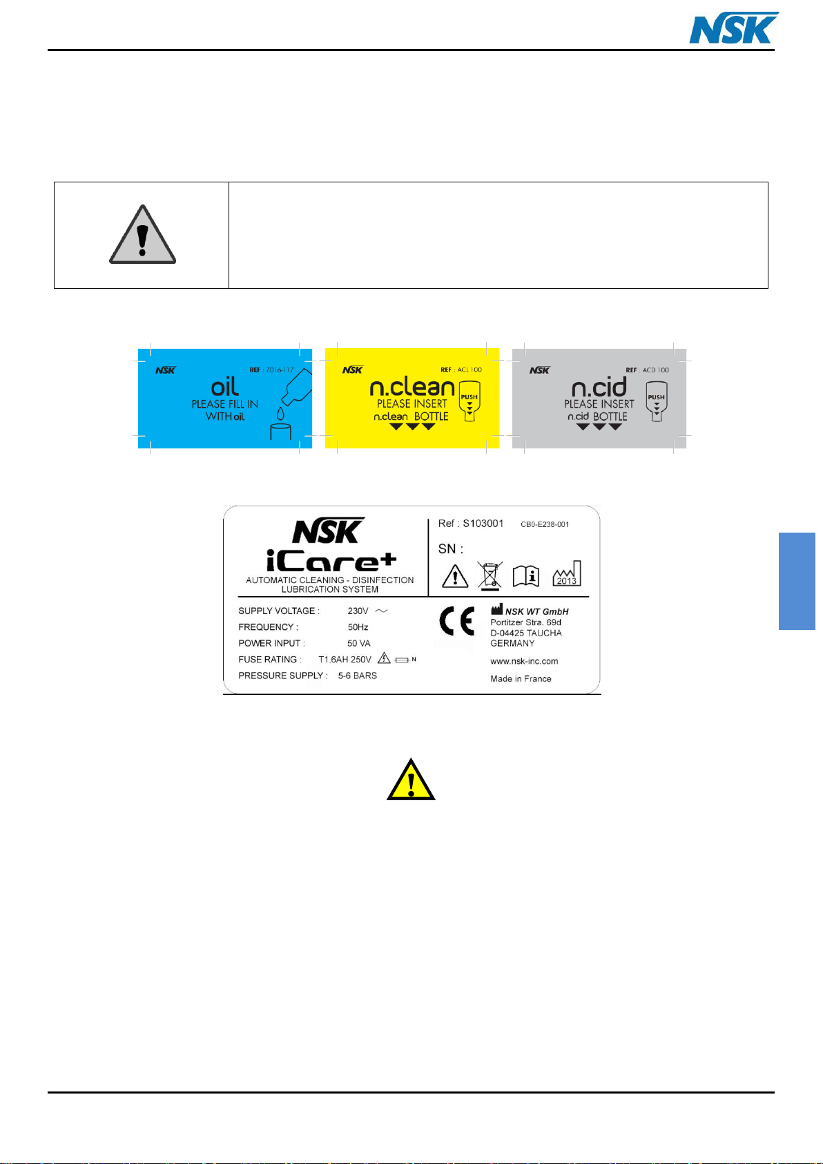
1.2.1. Adhesive safety labels
Adhesive safety labels have been placed for iCare+ device on important locations. These include storage instructions
of the bottles and the device and information about the device's features.
LA-1 LA-2 LA-3
LA-4
LA-5
Figure 1: List of safety labels for iCare+ device
LA-1: NSK OIL label (product for lubrication)
LA-2: n.Clean label (product for cleaning)
LA-3: n.Cid label (product for disinfection)
LA-4: iCare+ device label with serial number
LA-5: Warning label about risk that may be caused by the needles
iCare+ Operation Manual 10-8-1 p. 7
ENGLISH
Never handle the power cord with wet hands; risk of electrocution
CAUTION: NSK does not warrant the use of a power cord other than that
provided in the package.
Make sure the wall outlet has an earth connection with a differential
(breaker)
Be careful not to inject water into the device; fire risk as a result of short
circuits
Make sure to switch OFF the unit before any cleaning or maintenance
action; risk of electrocution
Do not attempt to dismantle any part of the device. In case of breakdown,
contact your retailer directly
In case of emission of smoke or a smell of burning, immediately switch off
the iCare+ device and contact your retailer directly
Do not use the iCare+ with flammable gases
1.2.2. Position of safety labels
The safety labels are glued on different parts of iCare+ device. The labels LA-1-2-3 are positioned on the internal
surface of the top cover and as for LA-4 it is placed on the bottom panel of the unit housing.
The label LA-5 is positioned near the housing for the bottles of products.
1.3. Individual safety measures
All the safety measures referenced below must be followed closely in order to prevent exposure to risks of the user.
iCare+ Operation Manual 10-8-1 p. 8

ENGLISH
Article n°
Description
Quantity
1
CD of installation with User Manual
1
2
Power cord
1
3
A 4/6 mm diameter tube for the pneumatic system
(length: 2 m) with “T” junction connector
1
4
iCare+ device
1
5
n.Clean, n.Cid, lubrication oil (Products not included
into iCare+ package. Must be ordered separately)
-
Upon delivery of the unit, please verify that the packaging has no damage
during shipment.
For shipment, always use the packaging of iCare+.
Keep the packaging away from children.
4 2 3 1 5
CHAPTER 2: DESCRIPTION OF iCare+ DEVICE
2.1. Packaging contents
iCare+ Operation Manual 10-8-1 p. 9
ENGLISH
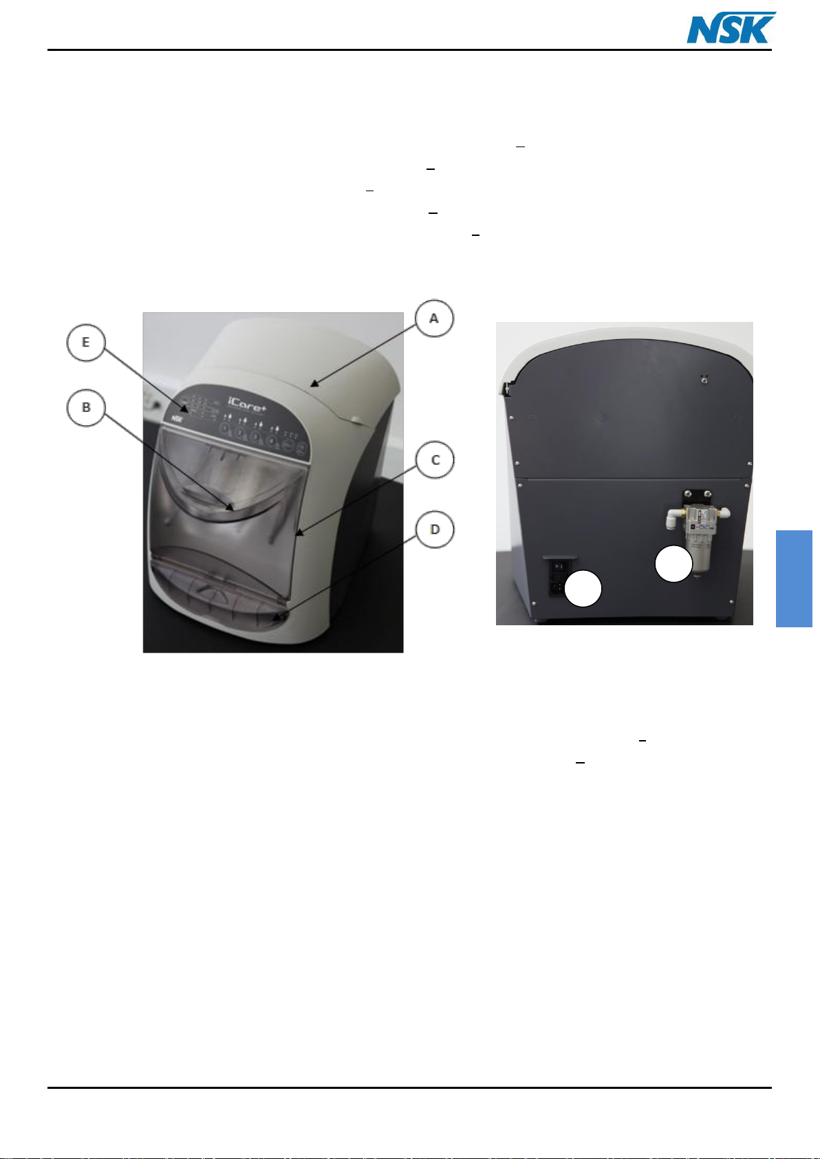
Figure 2: Front panel of iCare+ device
F
Figure 3: Rear panel of iCare+ device
G
Power supply inlet: F
Air filter: G
2.2. Description of iCare+ device
Top cover for access to the housing of implementation of products: A
Treatment chamber with connection of instruments: B
Door for access to the treatment chamber: C
Removable drawer for collecting the soiled products: D
Control panel which enables the user to monitor the device: E
iCare+ Operation Manual 10-8-1 p. 10
ENGLISH
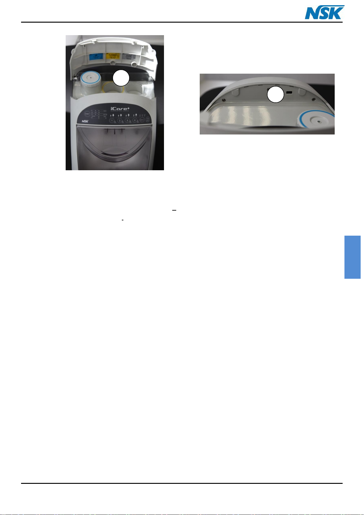
Housing for the different products: H
USB connection: I
H
Figure 4: Top rear panel of iCare+ device + USB connection
I
iCare+ Operation Manual 10-8-1 p. 11
ENGLISH
A
B
A'
E
D
F
1 2 3
4
C
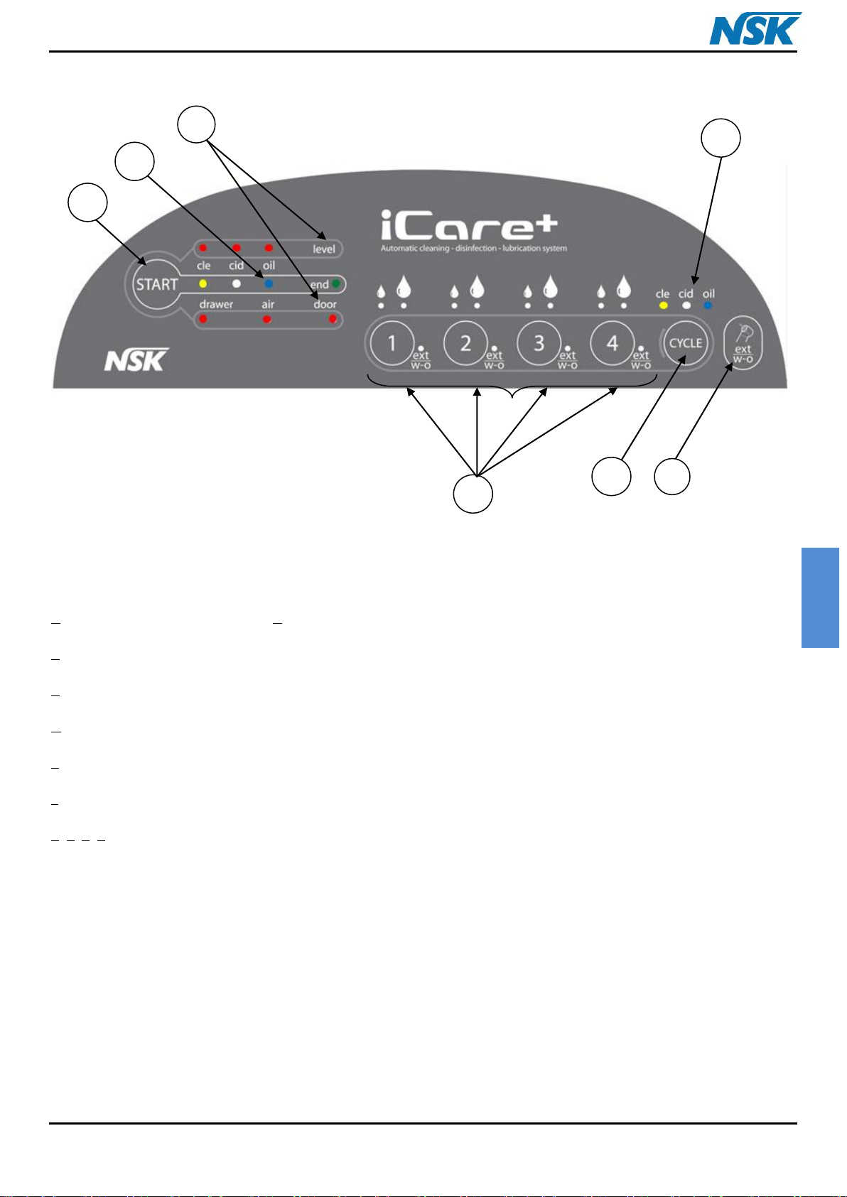
Figure 5: Control Panel of the iCare+ device
A: Cycle selection button A': Operating light indicators (LEDs) for cycle selected
B: Ext w-o (or Spray) button for selection of the model of the handpiece(s)
C: Instruments selection and Oil volume button (Short or Long mode)
D: Start-up button. This button can also be used to stop the unit during cycle (with a long press).
E: Cycle progress operating light indicators (LEDs)
F: Warning operating light indicators (LEDs) for consumables state and for drawer, air, door state
1, 2, 3, 4: Indicator of the type of instrument (if the indicator is lit: instrument with external spray or without spray)
iCare+ Operation Manual 10-8-1 p. 12
ENGLISH
CAUTION: The use of controls, settings or the implementation of procedures other
than those specified below may expose users and patients to danger
You should install the iCare+ device as requested below:
The device should be positioned on a flat, solid and level surface. The
maximum weight of the device, fully loaded, in conditions of use is 16 kg
The device should not be placed near a sink or any source that may splash it
The device should be placed in a room properly ventilated
The device should be kept away from any source of heat
Following the norm EN ISO 7494-2, the air quality provided to iCare+ has to
be dry, clean and free from bacteria and contamination.
The pressure of the air supply should be between 5 and 6 bar
The minimum air flow level provided to the unit is 50 L./mn.
It is necessary to follow the above mentioned parameters in order to avoid
some dysfunctions or damage of the unit.
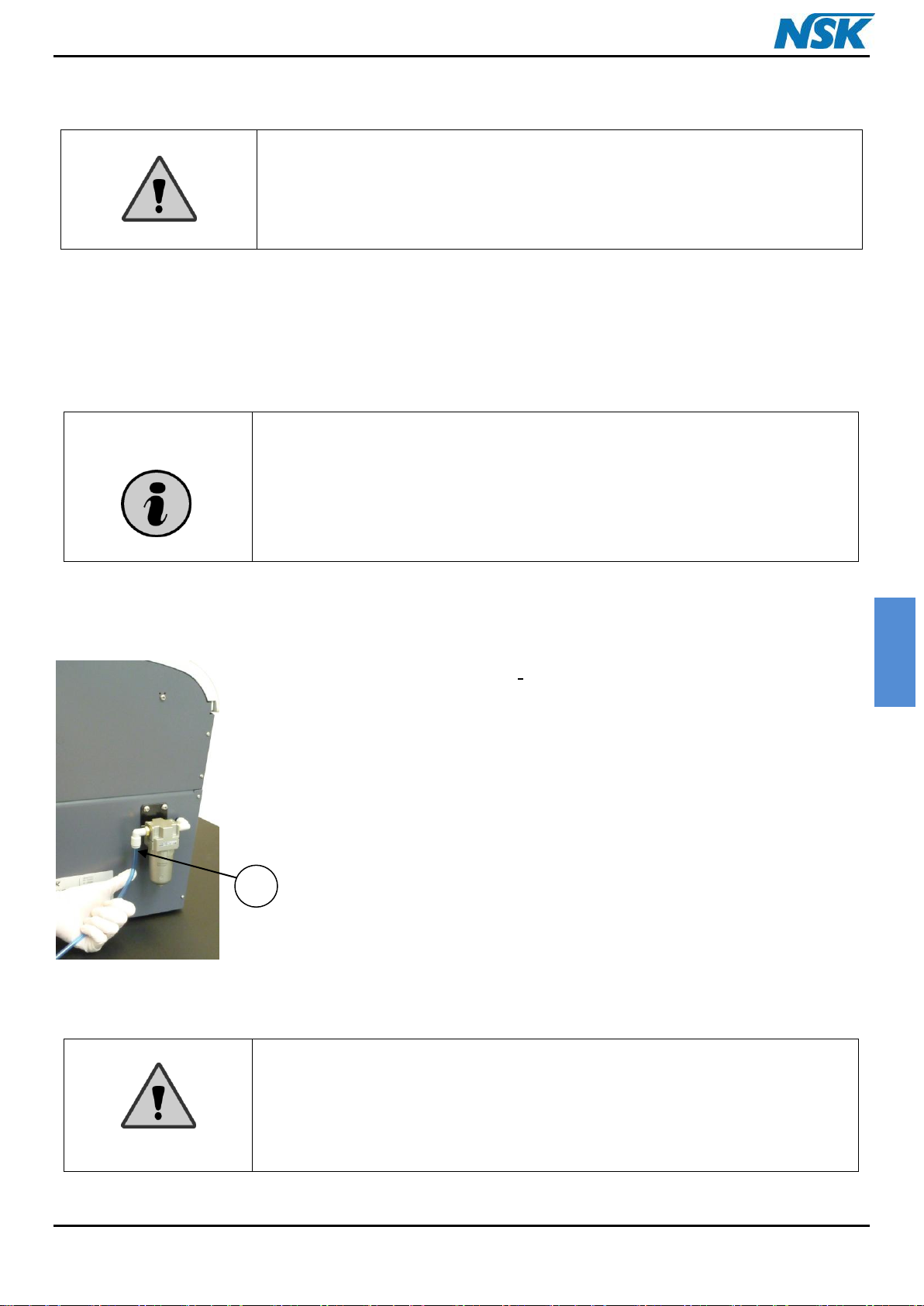
Figure 6: Connection of the tube in the
pneumatic system of iCare+ device
J
CHAPTER 3: USE of iCare+ DEVICE
3.1. Setup
3.1.1. Installing the iCare+ device
3.1.2. Connecting the air supply
Insert the air supply tube in the air filter: J, fixed on the Rear panel's device. Be sure that
the air tube is attached properly to the filter (see Figure 6). Connect the "T-shaped fast-on"
connector to the surgery compressor's air supply.
iCare+ Operation Manual 10-8-1 p. 13
ENGLISH
The pressure of the air supply must not be under 5 bar or above 6 bar. A
pressure sensor detects if the air pressure is too low or too high and stops
the machine. The operator is informed by an operating light indicator
positioned on the Control Panel.
Do not fold or deform the air supply tube
If you experience some difficulties during the connection step, please
contact your retailer
The air filter has an effective filter size of 5µm
K
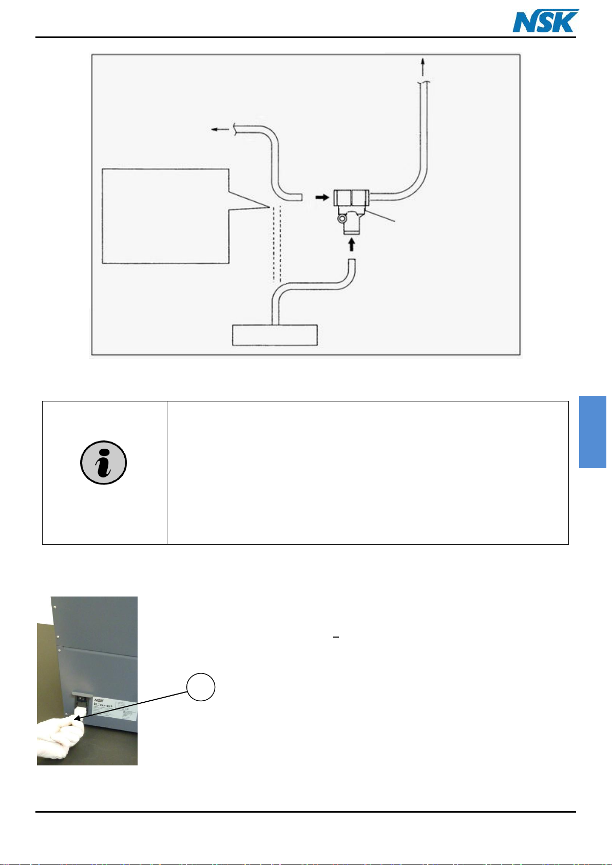
Figure 8: Electrical connection of
iCare+ device
Cut off the air arrival. Connect
the tube coming from the unit
and from the iCare+ device on
the “T” connector. Connect
the compressor’s arrival on
the “T” connector
EXAMPLE OF CONNECTION
DENTAL UNIT
AIR CONNECTION
iCare+ DEVICE
AIR COMPRESSOR
“T” CONNECTOR
Figure 7: Connection of the iCare+ device to the air system
3.1.3. Electrical connection
Connect the device by means of a power cord provided into the iCare+ package. This cable is
a Class I cable.
Just insert the power cord in the socket: K, on the iCare+ device's panel.
iCare+ Operation Manual 10-8-1 p. 14
ENGLISH
CAUTION: NSK do not warrant the use of other power cord than the one provided
with iCare+.
CAUTION:
Keep the products in a cool dry place and well ventilated. Not exposed to
sunshine.
Avoid any contact with skin and eyes.
It is recommended to use protective glasses and gloves during handling of
bottles or during emptying of the waste drawer.
In case of contact with the eyes, rinse the eyes with water with the eyelids
open for a sufficient length of time, and then seek ophthalmological advice
immediately.
In case of contact with skin, wash off immediately with soap and water. In
case of skin reactions, seek medical advice.
In case of inhalation, move affected person into fresh air. In case of irritation
of the airways, seek medical advice.
If swallowed, rinse out mouth and then drink plenty of water. Do not induce
vomiting. Seek medical advice.
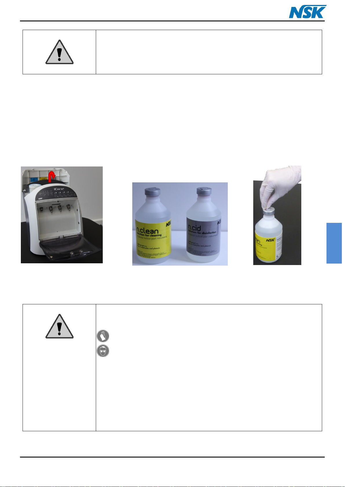
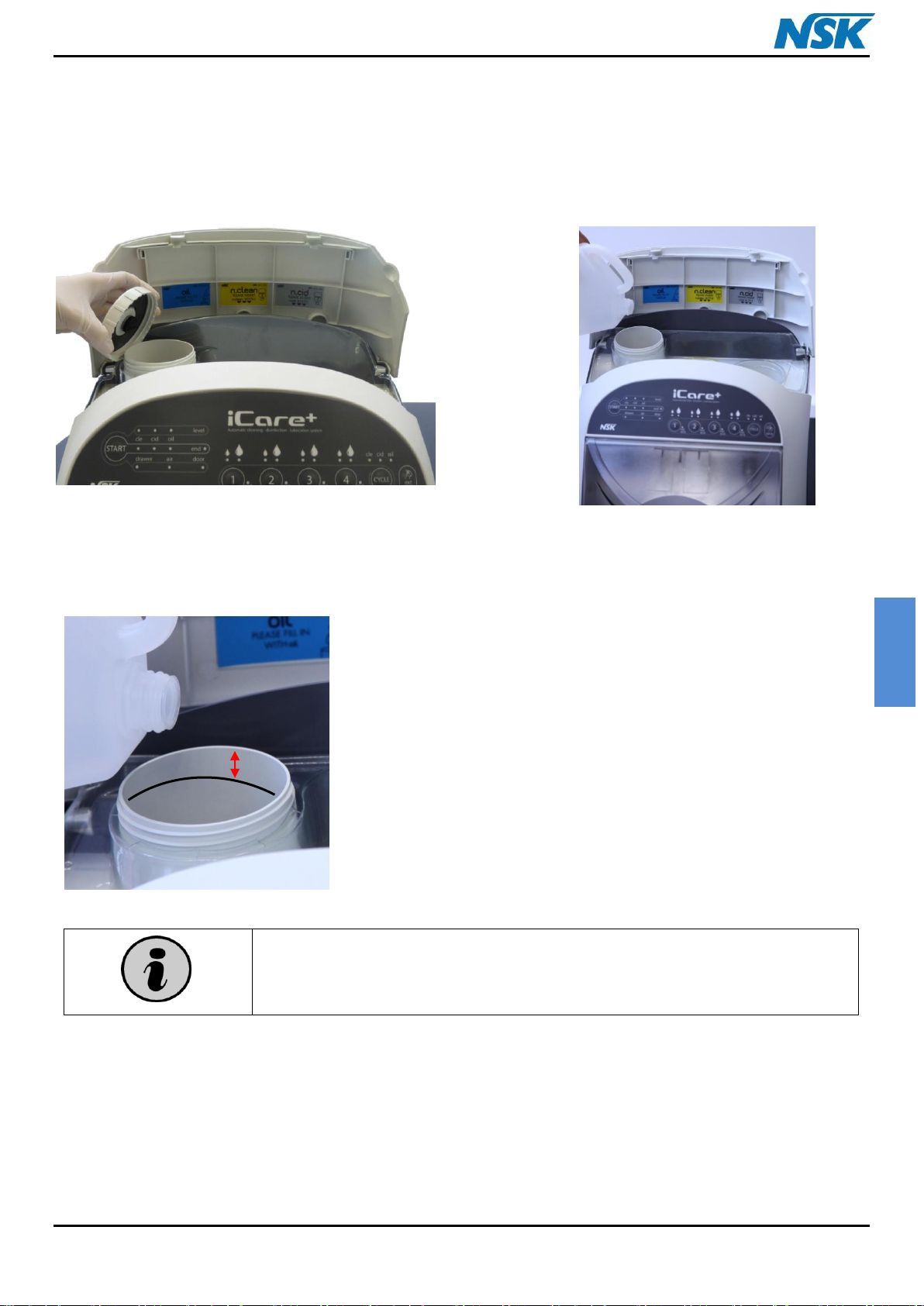
Figure 9: n.Clean & n.Cid ready to be positioned on iCare+ device
3.2. Implementation of the products
3.2.1. Positioning of n.Clean and n.Cid bottles Implementation of the products
Start by opening the Top cover and take the bottles of n.Clean and n.Cid solutions supplied (see Figure 9).
iCare+ Operation Manual 10-8-1 p. 15
ENGLISH
CAUTION: Do not forget to remove the metallic cap on each bottle, before starting
the implementation of the consumables; you may damage the iCare+ device.
For each bottle of solution or for the Oil, a coloured sticker is used to avoid
confusions between the products during the implementation of them:
For the n.Clean solution, a yellow sticker on its bottle and a yellow safety
adhesive label on its housing (of the Top rear panel) are glued
For the n.Cid solution, a grey sticker on its bottle and a grey safety adhesive
label on its housing (of the Top rear panel) are glued
The oil is directly poured into the tank (on the Top rear panel) on which a
blue safety adhesive label is glued
Always use n.Clean and n.Cid bottles supplied by NSK Europe GmbH.
The efficiency of the iCare+ device is optimized and certified for n.Clean and n.Cid
products.
Cleaning and disinfecting protocols have been calculated using these products.
The use of any other product may lead to a failure or damage of the iCare+ device or
of the instruments connected to, and the efficiency of the device will not be
ensured.
Therefore, in case of non compliance, the user will be considered as responsible.
CAUTION: When the bottles are not inserted, the needles, if reachable, can cause a
risk of injury
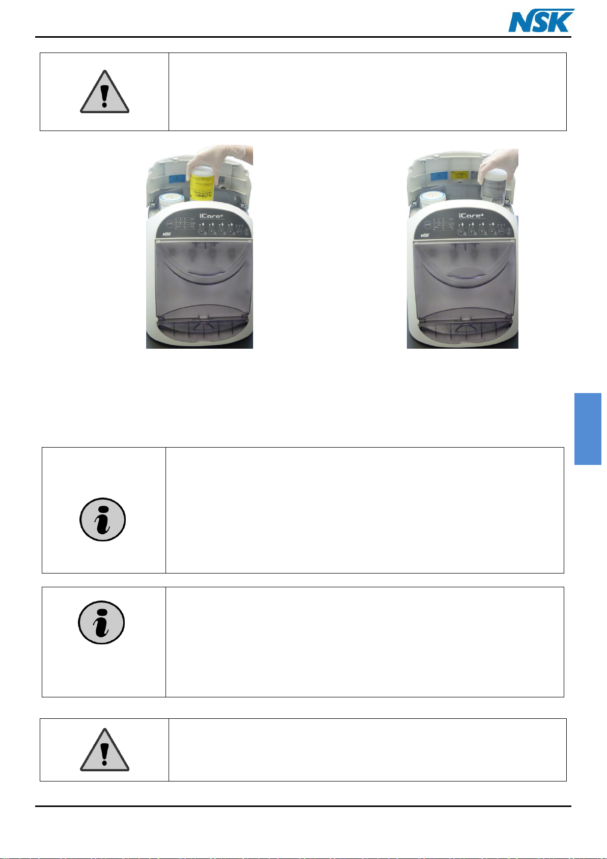
Figure 10: Implementation of
n.Clean bottle (500 mL)
Figure 11: Implementation of
n.Cid bottle (500 mL)
Push the bottle of n.Clean solution into the correct housing (see Figure 10) and after that do the same thing with the
n.Cid solution bottle (see Figure 11). To insert the bottles, a short pressure on them is enough. It is not necessary to
push them strongly because they can be damaged.
iCare+ Operation Manual 10-8-1 p. 16
ENGLISH
Always use NSK Oil for handpiece in the iCare+ device to ensure optimal
operating conditions
After filling the tank, be sure to have properly closed its cap
Figure 12: Unscrewing the Oil tank's cap
of iCare+ device
Figure 13: Filling the Oil tank of iCare+
device
20 mm
3.2.2. Filling the oil tank
Shake well the maintenance Oil. Unscrew the tank's cap (see Figure 12) and pour the Oil in (see Figure 13). Please fill
the tank up to 20 mm from the top edge of the tank. After filling, screw its cap back on.
Once the tank is filled and the cap properly attached, close the Top cover. After that you can start connecting the
different instruments.
iCare+ Operation Manual 10-8-1 p. 17
ENGLISH
Do not use the door as a support : do not put anything on the door when open.
3.3 Validation test
3.3.1. On site validation test
This test must be performed prior to first start-up. It consists of a series of tests in order to validate that the
functioning parameters are functioning after the installation of iCare+.
3.3.2. Periodical validation test
NSK recommend to perform this periodical validation test every year, in order to validate that the performance of
iCare+ is still optimum.
3.4. Connection of the instruments
3.4.1. Treated instruments
The iCare+ is a device whose function is to ensure the cleaning and disinfection of dental rotary and dynamic
instruments.
The iCare+ device allows the cleaning and disinfection of internal and external surfaces of different instruments. The
main instruments intended to be treated are handpieces: contra-angles and turbines.
The different types of instruments that can be treated by iCare+ device are listed in the table 1 (please refer to the
part 3.3.5. Selecting the type of instrument).
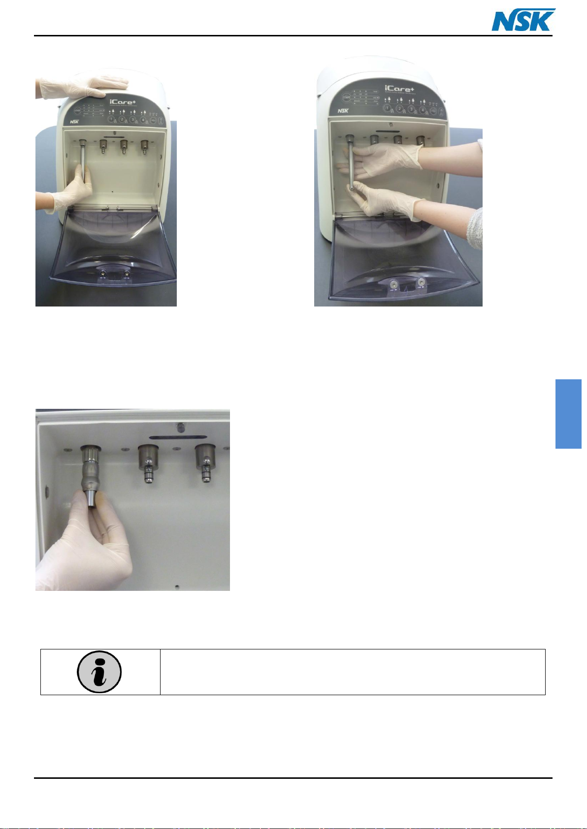
3.4.2. Installation of the instruments
With the iCare+ device, it is possible to connect 2 kinds of instruments by means of 2 different connectors:
Air turbine connector for turbines.
E-type connector for contra-angles.
To connect a turbine with Midwest 4 holes(in accordance with the ISO 9168 standard) , start by opening the door
and connect the turbine directly to turbine connector of the iCare+ (see Figure 14) and screw the ring on tightly (see
Figure 15). Finish this operation by closing the door. Take care of the position of the turbine connector.
iCare+ Operation Manual 10-8-1 p. 18
ENGLISH
It is necessary to use a specific iCare+ air turbine adaptor. These are especially
designed to deliver the right volume of product required for each instrument.
NSK does not guarantee a good working of the device with any other coupling.
Figure 14: Connection of one turbine
Figure 15: Screwing the ring on the Midwest
coupling
Figure 16: Change of turbine adaptor
To connect a turbine with other connection type, it is necessary to install the corresponding adaptor first (Please
refer to the list of available adaptors into the chapter 10).
Insert the adaptor and screw the ring on firmly; check the positioning
of the different nozzles.
iCare+ Operation Manual 10-8-1 p. 19
ENGLISH
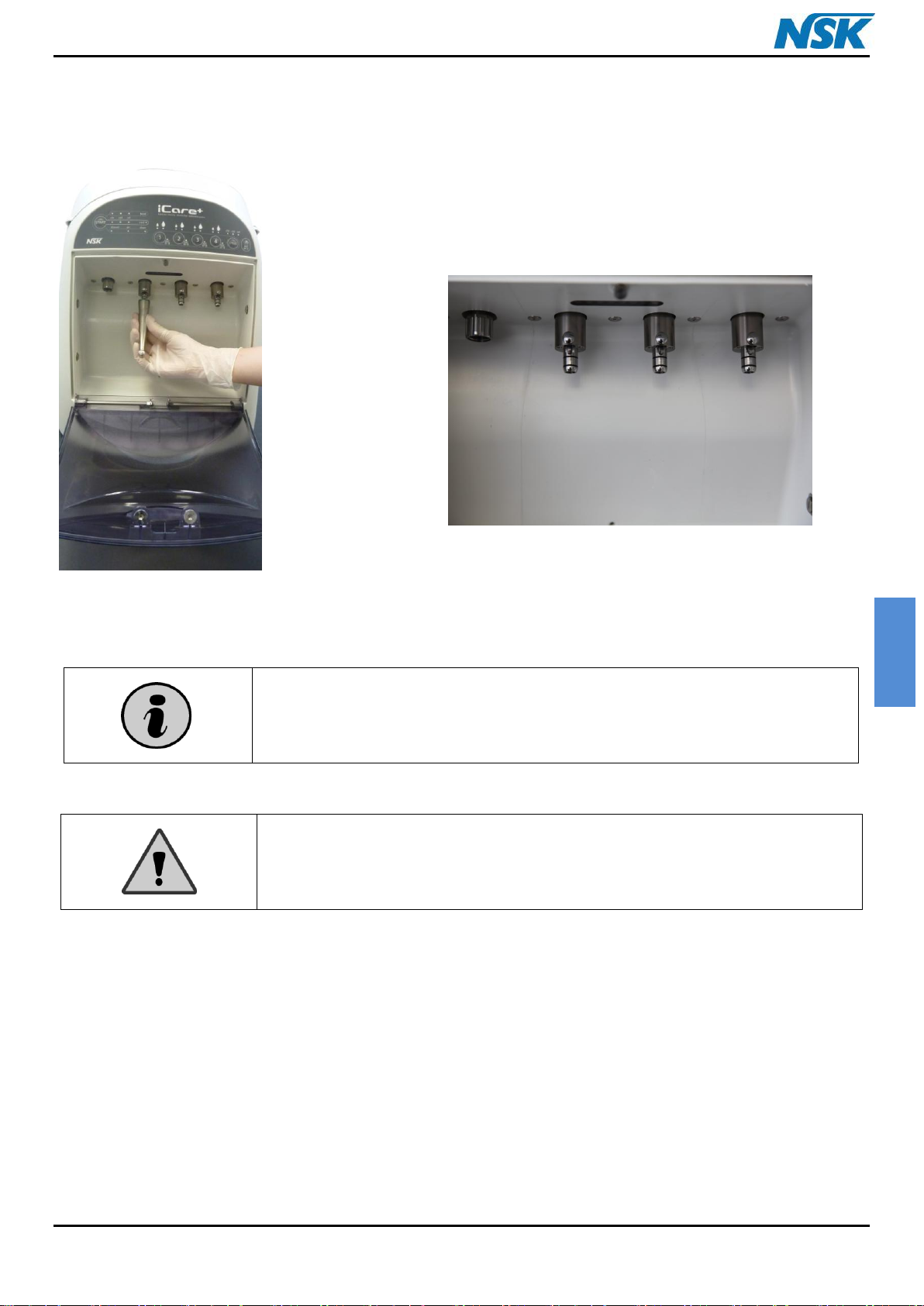
Place properly the contra-angle in the connector until you hear a “click”. In
this way, the contra-angle will be well maintained during the different
phases of the treatment.
CAUTION:
Please make sure to remove any bur from the chuck
Make sure also to remove any support/holder for snap-on caps
If not the dirt and liquid inside the instrument could not come out
Figure 17: Connection of a contra-angle
Figure 18: iCare+ version 1 with 1 air turbine
and 3 E-type connectors
To connect a contra-angle or a hand piece on e-type connectors, in accordance with the ISO 3964 standard, start by
opening the door and connect the contra-angle on the E-type connector (see Figure 17). Finish this operation by
closing the door.
3.4.3. Removing the instruments
For removing an air turbine, in accordance with the ISO 9168 standard, follow the description below:
Once the cycle has finished, you will hear a "BIP" sound and the green operating light indicator ("END" LED) will be
lit, start opening the door. After that, remove the turbine from the connection.
iCare+ Operation Manual 10-8-1 p. 20
ENGLISH
The operation is identical to remove a turbine Sirona type of its
corresponding adapter.
Retaining ring
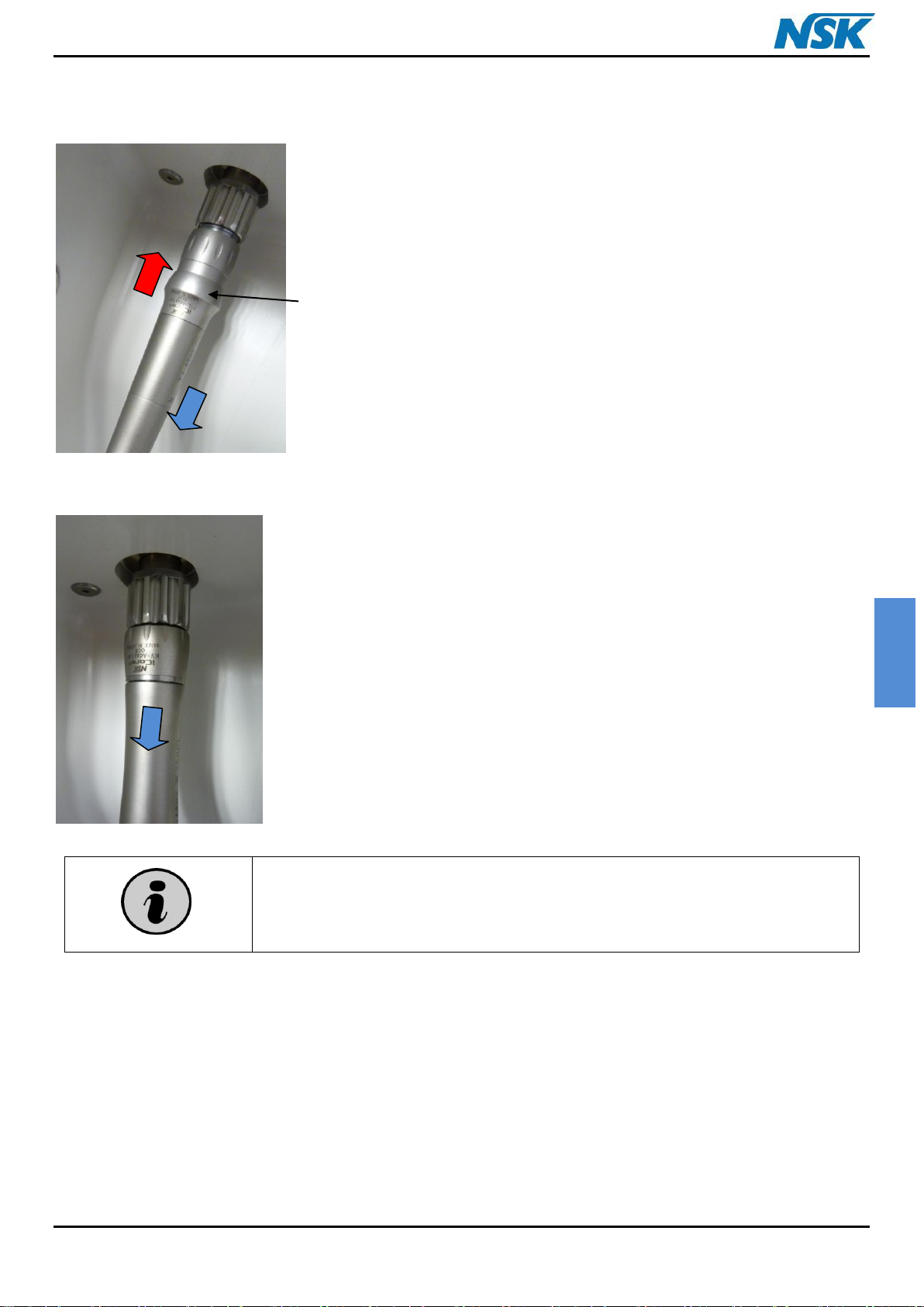
Removing a NSK turbine from its adaptor :
- Move up the retaining ring of the adaptor.
- Remove the turbine while maintaining the ring in upright position.
Removing a Kavo turbine from its adaptor :
- Remove the turbine by drawing down the instrument.
iCare+ Operation Manual 10-8-1 p. 21
ENGLISH
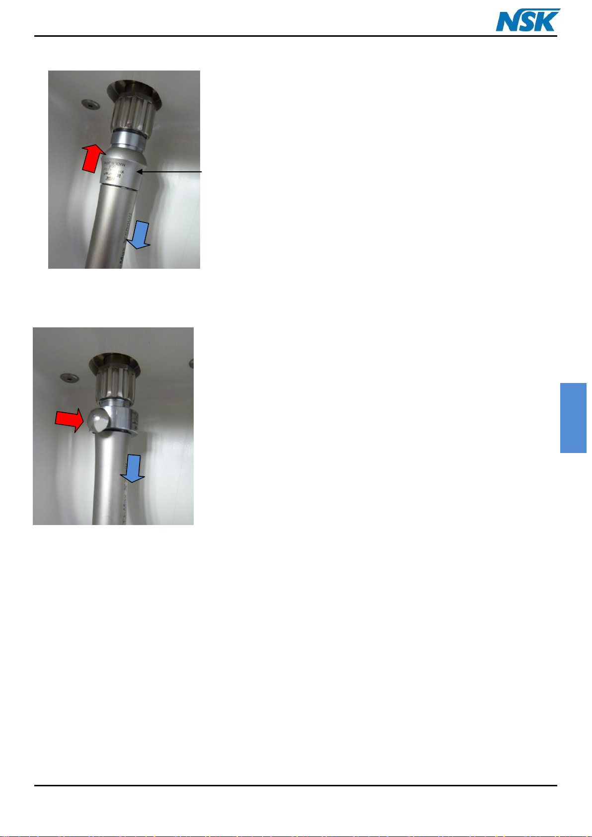
Retaining ring
Removing a W&H turbine from its adaptor:
- Move up the retaining ring of the adaptor.
- Remove the turbine while maintaining the ring in upright position.
Removing a Bien-Air turbine from its adaptor:
- Press the button on the adapter.
- Remove the turbine while keeping the button pressed.
For removing a contra-angle, in accordance with the ISO 3964 standard, follow the description below:
Start opening the door. After that, remove the instrument in the axial direction of the E-type connector by pressing
on the release button.
3.5. Programming of iCare+ device
Start by putting the ON/OFF switch, localized on the Rear panel, on position I.
3.5.1. The Control panel
The Control panel (see Figure 19) is composed of a series of control buttons and also of light operating indicators
(LEDs).
The configuration of the device, the progress in the cleaning process and the status of the sensors are directly
displayed on the front panel using 25 LEDs. Combinations of the LEDs provide additional information such as the
progress in the copy of the internal memory into the USB key.
iCare+ Operation Manual 10-8-1 p. 22

ENGLISH
A
B
A'
E
D
F
1 2 3
4
C
A total of 7 switches are available. One switch: (labeled “Cycle”) is used to select one of the 3 types of cycle to run:
Full cycle (Cleaning + Disinfection + Lubrication), partial cycle (Cleaning + Lubrication) or short cycle (lubrication
only).
The "ext-WO” button enables the user to select the type of handpieces: a handpiece without spray or external spray,
or by default with an inner spray.
4 switches enable to select/deselect the instruments to be processed and the volume of lubricant to be used.
The “Start” switch is used to start the programmed cycle or as an emergency stop.
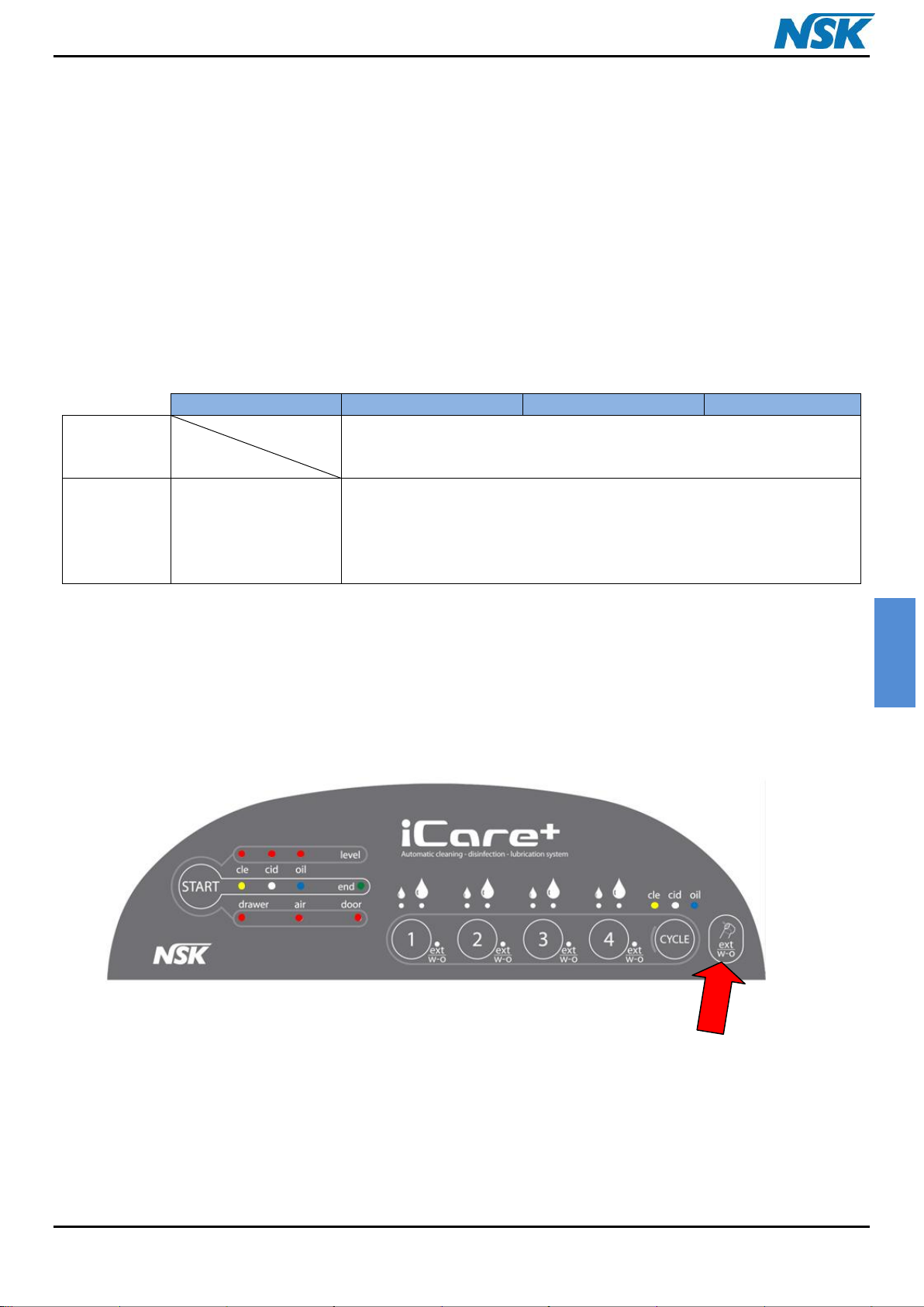
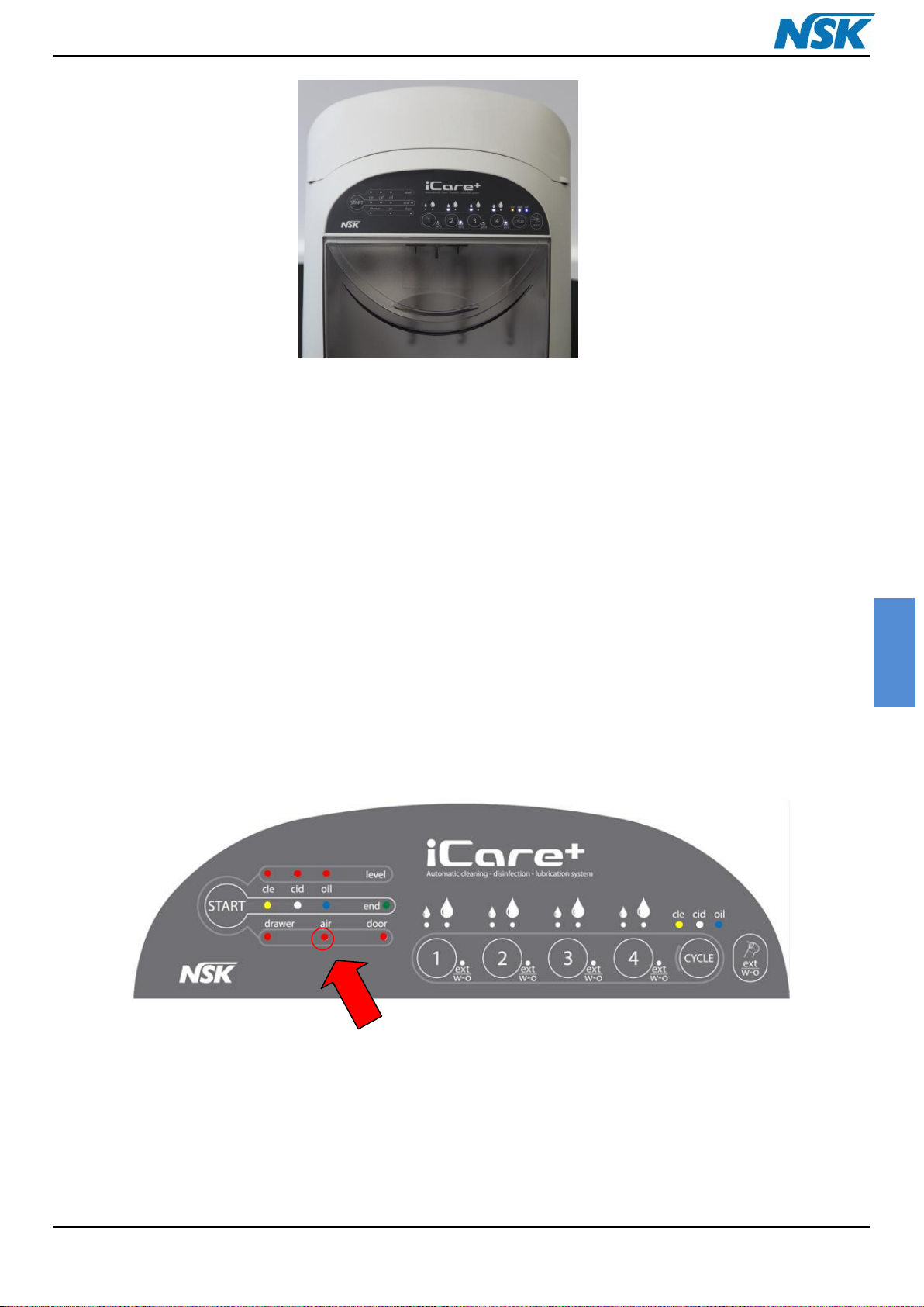
Figure 19: Control Panel of the iCare+ device's Front panel
A: Cycle selection button A': Operating light indicators (LEDs) for cycle selected
B: Ext w-o (or Spray) button for selection of the model of the handpiece(s)
C: Instruments selection and Oil volume button (Short or Long mode)
D: Start-up button. This button can also be used to stop the unit during cycle (with a long press).
E: Cycle progress operating light indicators (LEDs)
F: Warning operating light indicators (LEDs) for consumables state and for drawer, air, door state
1, 2, 3, 4: Indicator of the type of instrument (if the indicator is lit: instrument with external spray or without spray)
iCare+ Operation Manual 10-8-1 p. 23
ENGLISH
The volumes and the sequences of injection of n.Clean and n.Cid products are
directly programmed and monitored by the device itself, according to an accurately
defined and validated protocol by a medical institute.
Full mode
Partial mode
Short mode
Figure 20: Selection of the type of program for iCare+ device
3.5.2. Connecting the instruments
The instruments have to been connected in accordance to the description done in part 3.2.2.
3.5.3. Selecting the program
The treatment of the instruments is achieved by a cycle composed of 3 different steps:
1 cleaning phase : 6 min (for 4 instruments)
1 disinfection phase : 6 min (for 4 instruments)
1 lubrication phase : 1.5 min (for 4 instruments)
The “CYCLE” button enables the operator to choose between the 3 maintenance cycles:
Full maintenance cycle: Cleaning/Disinfection/Lubrication
Partial maintenance cycle: Cleaning/Lubrication
Short maintenance cycle: Lubrication only (similar function as for Care3plus)
th
A 4
pressure on the Cycle button manages the user to reset the choice of the cycle.
3.5.4. Selecting the instruments
By default, and as a measure of security, the iCare+ device dispenses the product to all the connectors. Here the
operator has to select the instrument(s) and choose the suitable Oil volume that he wants to be delivered:
Small drop corresponds to a normal volume (Short cycle)
Large drop corresponds to a specific volume for certain contra-angles (Long cycle for surgical contra-angle or
1:5 contra-angle for example)
2 unlit LEDs indicate that the instrument is deselected and so that no product will be sent through it
iCare+ Operation Manual 10-8-1 p. 24
ENGLISH
INSTRUMENT 1
INSTRUMENT 2
INSTRUMENT 3
INSTRUMENT 4
ONLY
DRIVE
CHANNEL
Contra-angle or handpiece with external spray or without spray
W/A +
DRIVE
CHANNELS
(2
CHANNELS)
Air turbine
Air Scaler
Contra-angle or handpiece with internal spray
Button for
selection of
External/Without
spray instrument
By default the Short cycle of oil is selected; press the button corresponding to the position where the instrument is
connected, once to select the Long cycle (large drop LED lit) and twice to deselect the instrument.
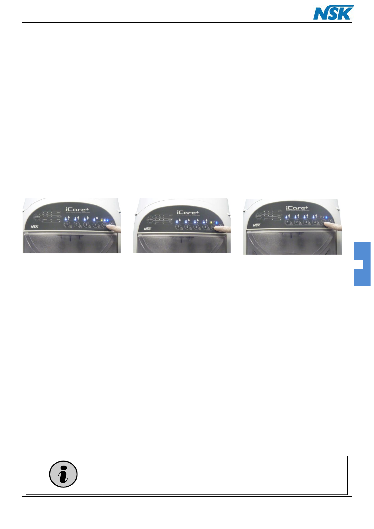
3.5.5. Selecting the type of instrument
In parallel, the user will be able to choose the type of instrument.
The iCare+ device is designed to enable the treatment of 2 models of dental rotary instruments:
Dental devices with only one drive channel
Dental devices with 2 channels: W/A + drive channels
All the different instruments that can be treated with iCare+ device are mentioned in the following table:
Table 1: List of different treatable instruments per model
Standard setting of iCare+ is designed for internal spray instruments. To make the selection for external or without
spray instrument, it is necessary to push simultaneously the “ext/WO button” and the button corresponding to the
position of the instrument without or external spray.
For example to change the model of instrument 2, the operator will have to press simultaneously the button "ext
W/O” and the button 2; see on Figure 21 below. The LED "ext W/O", near button 2, is now lit to inform the operator
that the instrument 2 is an instrument without spray or with external spray.
iCare+ Operation Manual 10-8-1 p. 25
ENGLISH
Figure 21: iCare+ device with lit W/O LEDs
In parallel of the function of external spray instrument, the unit can control if there is a mistake for the programming
of the button SPRAY or if a channel is blocked.
For example, if the user selects an instrument as an external spray instrument (but in reality, the instrument has an
internal spray), the unit is able to detect it.
As a reverse case, if the user connects an instrument with external spray without using the button “ext W/O” (to
select external spray: “ext-w/o” LED), the unit is able to detect that the selection is wrong because this instrument
has external spray.
To inform the user of these problems, the unit will stop and the Air LED will blink, with a “BIP” signal heard. In
parallel, the concerning instrument is indicated by white LED blinking (oil indicator and/or ext-WO LEDs).
To restart the unit, first open the door, remove the instrument (to reduce the remaining pressure) reconnect the
instrument, and then close the door.
If the problem happens again, remove the handpieces and push the button “Start”.
Check the instruments (in case of possible blocked channels).
iCare+ Operation Manual 10-8-1 p. 26
ENGLISH
START button allows starting the programmed cycle for the selected
instruments. If a problem happens, or that you wish to stop the unit during a
cycle, START button allows also stopping the unit by a long press.
The cycle is then stopped, the settings and selections are kept and the
machine stays on standby. By pressing again the START button, the cycle is
re-launched from the beginning with the same settings.
If the door is open while the unit is on standby, the settings and selections
are initialized.
If the user needs to stop the cycle during process, a long press on “START” button
will stop the unit.
When the “Mode” light indicator (small/big amount of Oil) is switched off,
the connection (1, 2, 3 or 4) is not selected
Just after purchasing iCare+ device, or after a long period of no use, run the
device empty (without instruments)
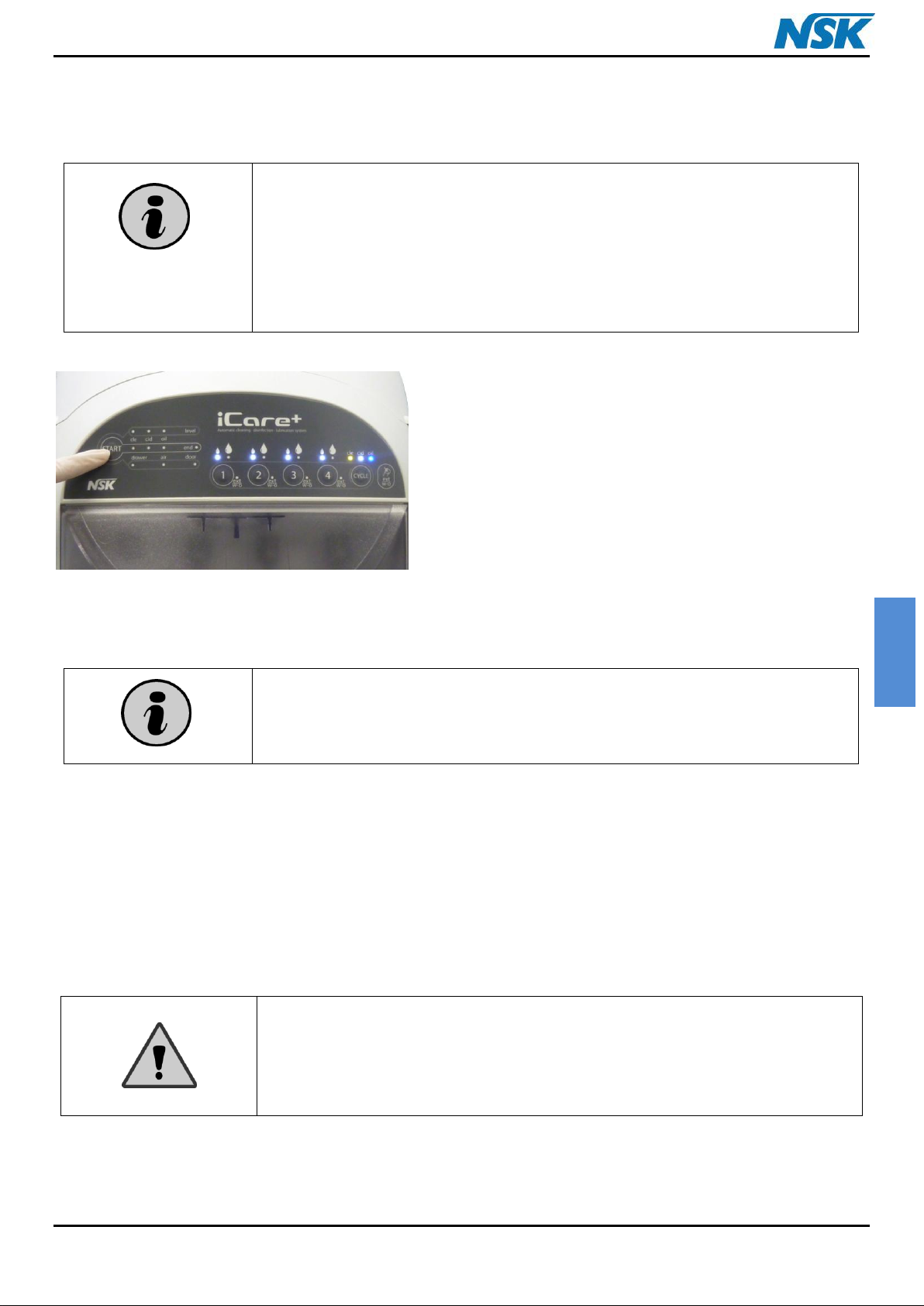
Figure 22: Launching the treatment cycle
3.5.6. Launching the cycle
Once the program is chosen, press START button to launch the cycle (see Figure 22).
A series of LEDs, positioned on the Control panel and on the treatment chamber, indicates the progress of the cycle:
Yellow LEDs are used to provide information of cleaning phase
White LEDs are used to provide information of disinfection phase
Blue LEDs are used to provide information of lubrication phase
Once the cycle completed, green LEDs ("END" LED + treatment chamber LED) are lit and inform the user that the
instruments are ready to be released from the unit.
iCare+ Operation Manual 10-8-1 p. 27
ENGLISH
In order to facilitate the external cleaning, we recommend using disinfectant
wipes (without protein fixation)for handling the instruments while
connecting them to the unit and rub slightly them before connecting in case
of important soils. It will help to liquefy the soils and stains located on the
outside surfaces.
At the end of the cycle, open the door and remove the instrument with a
disinfectant wipe (without protein fixation).
CLEANING PHASE (X3) :
- Injection of n. Clean product inside the
instrument (W/A + body channels)
- Simultaneous injection of n.Clean
product outside the instruments
(external surfaces)
- Action time of the liquid (30 s)
DISINFECTION PHASE (X1) :
- Injection of n.Cid product inside the
instrument (W/A + body channels)
- SImultaneous injection of n.Cid
outsite the instruments (external
surfaces)
- Action time of the liquid (120 s)
- Air blowing time
LUBRICATION PHASE (X1) :
- Injection of Oil inside the
instrument (body of the
instrument)
- Air blowing time
Figure 23: Treatment cycle of iCare+ device
iCare+ Operation Manual 10-8-1 p. 28
ENGLISH
CAUTION : All the cleaning operations should be performed after having
disconnected the iCare+ device from the main power supply
Do not smoke in the room where the device is kept
You should clean the iCare+ device as requested below:
Always use a soft cloth to clean the metallic and plastic parts of the device
Only use detergents that contain a very low level of alcohol (with no protein
fixation agent)
Never attempt to clean areas, that are difficult to access, with sharp objects
Be careful when cleaning the Control panel and never use aggressive
detergents
FREQUENCY / NUMBER OF CYCLES
OPERATION
PART
NUMBER
DESCRIPTION
Every
week
50
Cleaning the treatment chamber
--
4.2.1.
Every
week
50
Cleaning the external parts
--
4.2.2.
2-3 times per
week
15
Emptying the used products of the
drawer
--
4.2.3.
Every
week
50
Cleaning the drawer
--
4.2.4.
1 year
Replacing the junction support blister
S103205
4.2.5.
When blown
Replacing the fuse(s) of the supply inlet
On demand
4.2.6.
CHAPTER 4: USER MAINTENANCE
There are two different types of maintenance that have to be distinguished; general maintenance, that is regularly
performed by the user and the specific maintenance performed by a skilled technician from NSK support.
Only skilled technician from NSK or people trained by NSK, are allowed to perform specific maintenance.
4.1. General cleaning guidelines
4.2. General maintenance guidelines
Table 2: Frequency of maintenance for iCare+ device
iCare+ Operation Manual 10-8-1 p. 29
 Loading...