

Page 1
Operating instructions
Edition V3-6-5.2
Page 2

Inhalt
1. Important notes ............................................................................................................................................. 3
1.1 General safety guidelines ............................................................................................................................. 3
1.2. Used symbols ............................................................................................................................................... 4
1.3 Intendend use ............................................................................................................................................... 5
1.4 Short description .......................................................................................................................................... 5
1.5 Combination with other products .................................................................................................................. 5
1.6. Hygiene standards ....................................................................................................................................... 6
1.7 Standards and guidelines ............................................................................................................................. 6
1.8 Terms ........................................................................................................................................................... 6
2. Scope of delivery .......................................................................................................................................... 7
2.1 Basic unit ...................................................................................................................................................... 7
2.2 Equipment .................................................................................................................................................... 7
2.3 Accessories, consumables, spare parts, service partner ............................................................................. 7
3. Warranty ....................................................................................................................................................... 7
4. EMC Notice ................................................................................................................................................... 7
4.1 Guidance and manufacturer’s declaration – electromagnetic emissions ...................................................... 8
4.2 Guidance and manufacturer’s declaration – electric immunity ..................................................................... 9
4.3 Electromagnetic Environmental Recommendations - Separation distances between portable and mobile
RF communications equipment and DENTALONE ................................................................................................ 11
4.4 Essential performance ................................................................................................................................ 11
5. Environmental conditions ............................................................................................................................ 12
6. Storage and transport ................................................................................................................................. 12
7. Use and removal of transport cover .......................................................................................................... 13
8. Use ............................................................................................................................................................. 14
8.1 Description of components ......................................................................................................................... 14
8.2 Preparation / initial operation ...................................................................................................................... 15
8.3 Filling the water tank .................................................................................................................................. 16
8.4 Completion and arrangement of instruments.............................................................................................. 17
8.5 Operating elements / displays .............................................................................................
8.6 Instruments................................................................................................................................................. 18
8.6.1 Straight handpieces and contra-angles *) ............................................................................................. 19
8.6.2 Brushless motor Ti-Max NLX-nano ....................................................................................................... 19
8.6.3 Ultrasrasonic scaler VARIOS 170 LUX ................................................................................................. 20
8.6.4 Multifunction syringe ............................................................................................................................. 22
8.6.5 Suction .................................................................................................................................................. 23
9. Cleaning, maintenance, disinfection and sterilization .................................................................................. 23
9.1. General ............................................................................................................................................................ 24
9.2. Disinfection, cleaning and sterilization of instruments and handpieces ........................................................... 24
9.3. Cleaning and sterilization of drills and abrasive bodies ................................................................................... 25
9.4. Cleaning of surfaces which cannot be sterilized .............................................................................................. 25
9.5. Water pipes and water tank ............................................................................................................................. 25
9.6. Suction system ................................................................................................................................................ 26
9.7. Recommended disinfection and cleaning agent .............................................................................................. 26
10. Maintenance .......................................................................................................................................... 26
10.1. Regular maintenance works ................................................................................................................. 26
10.2. Maintenance intervals ........................................................................................................................... 26
10.3. Maintenance of the compressed air reservoir ................................................................................................ 27
10.4. Replacing the hand piece cords .................................................................................................................... 27
11. Malfunctions and trouble-shooting ......................................................................................................... 28
11.1. Fault diagnosis .............................................................................................................................................. 28
11.2. Fault signals ................................................................................................................................................. 29
11.3. Change of fuse ..................................................................................................................................... 29
11.4 Manual unlocking the console .............................................................................................................. 30
12. Disposal advices ................................................................................................................................... 30
13. Technical data ....................................................................................................................................... 31
Annex A.................................................................................................................................................................. 33
Operation manual Multi-control panel ..................................................................................................................... 33
Annex B................................................................................................................................................................. 43
Operation manual Ultrasonic Scaler Varios 170 ..................................................................................................... 43
Annex C ................................................................................................................................................................. 52
Operation manual Micromotor NLX nano ............................................................................................................... 52
....................... 18
Page 2 of 54
Page 3

1. Important notes
In order to get to know the advantages of the treatment unit and to guara ntee patient safety it is
absolutely necessary to thoroughly read the instructions for use before putting the device into
operation.
1.1 General safety guidelines
1 The unit is built under consideration of the requirements of the German Act of Medical Devices or
the guideline 93/42/EWG for medical devices and meets the essential requirements of annex I.
The product is a device of class IIa according to annex IX of regulation 9 of guideline 93/42/EEC
for medical devices.
2 The safety technical standard is based on the VDE-regulation for electromedical devices DIN IEC
60601 part 1 / DIN VDE 0750 part 1.
3 Caution: To avoid the risk of electric shock, the device is to be connected with supply networks
which are installed according to the regulations for medically used rooms (IEC 60364-7-
710:2002-11 or DIN VDE 0100-710).
4 The device has to be located in such a way, that a separation from the mains by pulling the mains
plug is easily possible in the event of a fault.
5 The product is a medical device and must be used in accordance with the rules of the medical
devices Act (MPG) by authorized personnel only. The user must guarantee proper handling due
to his education or skills and be familiar with the operation of the device.
6 Before operating the unit, the user must ensure the reliability and orderly condition of the device.
7 For safety reasons, the equipment must remain switched off when it is unattended. In that case
the power switch is always to be turned off.
8 The unit is not suitable for operation in potentially explosive areas
9 The product is subject to regular safety checks. The medical devices Act (MPG) and the
corresponding regulations are to be observed by the operator fully.
Scope and deadlines of the technical safety checks are prescribed as follows:
At least every 12 months must be carried out following listed safety controls in compliance with
DIN VDE 0750 and DIN VDE 0751 like perform:
Visual inspection of device and accessories, protection ground conductor checking according to
DIN VDE 0751, equivalent leakage current measurement according to DIN VDE 0751, functional
testing of the unit in accordance with the accompanying documents.
We recommend keeping a medical book in which the test results of the safety checks are
documented.
10 As manufacturer of the device, we can assume responsibility for the safety properties of the unit
only if maintenance and repair is performed by us or an authorised agent, if the prescribed
service intervals are observed and the device is used in accordance with the operating
instructions.
A further condition is that components, affecting the safety of the device, are replaced only with
original parts.
Technical service documents are available for companies authorized by us for the service and
repair.
11 Warning: Any change of the device is NOT permitted.
12 In case of maintenance, inspection or repair you should request a certificate of type and scope of
work of the company. The certificate must contain the date of implementation, as well as name of
the company with signature (see also MDD, DIN VDE 0750 / DIN VDE 0751).
13 The user has to comply with all valid laws and directives for medical devices as well as national
regulations, in particular, the work safety regulations and accident prevention measures
14 Portable communication devices which emit radio waves (E.g. mobile phones) can affect the
medical equipment. Don’t use such devices near the Dentalone (refer page 8, table 4.3 )
15 The instruments Motor, Scaler and Syringe are equipped with LED light. Eye damage may result
if the LED is directed straight into the eyes. Do not look into or turn it to the eyes of the patient.
Page 3 of 54
Page 4

1.2. Used symbols
Caution – check for specific warnings or precautions!
Read the instructions for use!
Caution line voltage!
A disposal through household waste/residual waste is not allowed. Note recycling information!
Application components type B: device with earth connection
Manufacturer
IP30 Device is protected against penetration of solid bodies > 2,5 mm;
Device is protected against dripping water. Vertically falling dripping water may not have any
adverse effect.
Don’t tread on! Do not overload!
Do not use outside closed rooms!
Autoclavable on max. 135°C
Direction up
Protect from moisture
Recycleable
Caution fragile!
Handle with care!
Conformity according to all European Directives
Temperature limits for storage and transport
Limits of humidity for storage and transport
Limits of atmospheric air pressure for storage and transport
Page 4 of 54
Page 5
1.3 Intended use
The device Dentalone is a portable dental treatment unit and is used for outpatient and stationery
general treatment of teeth.
The product is designed only for dental use by qualified personnel.
The NLX nano motor is for cutting / polishing as required during general dental treatment.
The Scaler Varios 170 generates ultrasonic waves intended for use in dental applications such as scaling,
root canal treatment, periodontal and cavity preparation.
For the choice of the treatment locations the information in the operating instructions are decisive.
Contra-Indication:
Dentalone: The device should NOT be used for surgical, oral surgical treatments and implant
surgery.
Scaler:
Do not use for patients anesthetized under laughter gas (Nitrous Oxide).
Keep away from explosive substances and flammable materials.
1.4 Short description
Dentalone is a self-contained dental unit with an integrated water and compressed air supply as well as a
low volume suction. The essential features include:
Do NOT use the scaler on patients with cardiac pacemakers.
Mobile unit
Ergonomic design due to height-adjustable console
Compact construction, minimal space requirement.
Equipped with Ultrasonic Scaler, Electric Micro-motor, Multifunction syringe and Saliva ejector.
LED Light on Motor, Scaler and Multifunction syringe for better illumination of the treatment area
Motor control with stable tractive power in each speed range.
Ergonomic operation of handpieces/ contra-angles in combination with NLXnano electric micro-
motor.
No suck-back spray supply on micro-motor, ultrasonic scaler and multifunction syringe.
Clearly arranged work console with integrated swivelling instrument holder, centrally arranged
multi-function control panel and storage space for accessories.
Automatic instrument recognition of active instrument
Clearly visible graphic display of the device status and the set parameter
Quick release connection of all instrument hoses for easy exchange
Easy-care housing
Base with wheels combined with the cover and integrated telescopic handle makes transport
comfortable as a trolley
1.5 Combination with other products
The dental micro-motor NLXnano can be used with instruments from NSK, but also with instruments from
other manufacturers with E-type fitting.
Furthermore there is no intended combination with other products.
The ultrasonic scaler Varios 170 should be used exclusively with the correct tips from NSK.
The multi-function syringe should only be used with tips of the manufacturer.
The saliva ejector can be used with any 6 mm or ¼” tips which are approved as dental consumables
(CE sign).
For all accessories and consumables the hygiene regulations of the manufacturer shall apply.
Page 5 of 54
Page 6
1.6. Hygiene standards
1 All objects which get into the oral cavity of a patient have to be pre-treated to avoid any infection
with any disease.
2 All objects which directly or indirectly get in touch with the mouth of the patient are regarded as
contaminated. Contaminated objects MUST NOT get in contact with other patients without any
disinfection/sterilization.
3 Direct unprotected contact with saliva or blood has to be avoided.
For your own safety you MUST, wear suitable protective equipment during the treatment in
accordance with country-specific occupational safety and health regulations, E.g. gloves, goggles
and face mask.
4 It is extremely important that any patient treatments planned in advance, thus all necessary
objects are available at the beginning of the treatment to save time and reduce the risk of cross
contamination.
5 To avoid cross contamination clean and dirty instruments must be kept separately.
6 All objects, which are directly or indirectly in contact with the patient, must be either professionally
disposed of following treatment or they need to be processed for cross infection control
7 The water tank should be filled with of drinking water quality or treated (purified) water. As an
additive the product ALPRON is recommended.
1.7 Standards and guidelines
Standard Contents
2006/42/EC Machinery Directive
93/42/EC Medical Device Directive
DIN EN 1041 Information supplied by the manufacturer of medical devices
DIN EN 60529 Degrees of protection provided by enclosures ( IP-Code )
IEC 60601-1 Medical electrical equipment; - Part 1: General requirements for safety
IEC 60601-1-2 Medical electrical equipment; Part 1: Electromagnetic compatibility
DIN EN 62304 Medical device software - Software life-cycle processes
IEC 60601-1-6 Medical electrical equipment - Collateral standard: Usability
DIN EN 980 Graphical symbols for use in the labelling of medical devices
DIN EN ISO 10993-1 Biological evaluation of medical devices
DIN EN 14971 Medical devices - Application of risk management to medical devices
EN ISO 7494-1 Dentistry - Dental units - Part 1 General requirements and test methods
EN ISO 7494-2 Dentistry - Dental units - Part 2 Water and air supply
DIN EN ISO 14457 Dentistry – Handpieces and motors
DIN EN ISO 22374 Dentistry - Dental handpieces - Electrical-powered scalers and scaler tips
EN ISO 10079-3 Medical suction equipment - Part 3: Suction equipment powered from a
vacuum or pressure source
1.8 Terms
Term Description
EMC Electromagnetic Compatibility
Instrument Applied part
Page 6 of 54
Page 7

2. Scope of delivery
2.1 Basic unit
The scope of delivery of the basic unit additionally includes the following components:
1 piece Cover with telescopic handle
1 piece Water tank incl. screw cap
1 piece Waste container incl. screw cap with integrated filling level sensor
1 piece Power Cord with non-heating apparatuses plug
1 piece Instruction for use
1 piece Foot pedal
Accessories
Motor: 1 piece Autoclave plug
1 piece Motor Cap for autoclave
1 set O-Rings (3 x black o-rings)
1 piece O-Ring blue
Scaler: 1 piece Sterilization cassette
3 piece Tip Wrench
1 piece Scaler Tip type G4
1 piece Scaler Tip type G6
1 piece Scaler Tip type G8
2 pieces O-Ring
2.2 Equipment
(Instrument holder equipped from the left to the right side)
Scaler with light “VARIOS 170 LUX” (separately packed)
Micromotor NLX nano with light (without handpiece/contra-angle *)
Multi-function Syringe
Saliva ejector (without cannula)
(not in the sense of the directive)
2.3 Accessories, consumables, spare parts, service partner
Consult your NSK-dealer for more information about specifications, accessories, consumables, spare
parts and service partners.
3. Warranty
The manufacturer's warranty is 1 year from date of purchase for provided the unit has been properly
commissioned and used in appropriate conditions. The manufacturer reserves the right to determine the
cause of any problems and to analyze.
Consumables parts and wearing parts are not covered by the warranty.
The warranty will lapse,
- if non-approved materials and liquids as described in the instruction for use are being used,
- if any modification on the unit is made by the customer or other unauthorized persons,
- if the device is used for any other purpose as its intended use,
- if damage is caused by gross negligence or due to improper use.
4. EMC Notice
The DENTALONE is subject to special precautions regarding EMC and must therefore be installed
and used according to the EMC notes in this operation manual.
The Dentalone may cause radio interference or it can interfere with the operation of devices in the vicinity.
If the location in which the DENTALONE is used exceeds the applicable RF compliance level mentioned
above, the DENTALONE should be checked to verify normal operation. If abnormal performance is
observed, additional measures may be necessary, such as reorienting or relocating the DENTALONE.
Portable and mobile RF communications equipment can affect the DENTALONE.
The following cables / components are part of the DENTALONE and can be used exclusively on the
DENTALONE (except power cord):
Page 7 of 54
Page 8
Component Ident number Cable type length
Power cord 31338.1
H05VV-F 3x0.75mm
Scaler cord VALux-SC 37075 2x0.25mm2 unshielded + 2x0.16mm
unshielded
Motor cord NLX CD 37074 3x0.25mm2 unshielded + 2x0.16mm
2
unshielded 2,0 m
2
2
1,2 m
1,2 m
unshielded
Multifunction syringe 57066
2x0.25mm2 unshielded 1,2 m
Foot switch 37100
4x0.16mm2 unshielded 2,0 m
Scaler VA2-LUX-HP
E351050
Motor NLX nano E1044051
Use of other cables may result in increased emissions or decreased immunity.
4.1 Guidance and manufacturer’s declaration – electromagnetic emissions
The DENTALONE is intended for use in the electromagnetic environment specified below.
The customer or the user of the DENTALONE should assure that it is used in such an environment.
Emissions test Compliance Electromagnetic environment - guidance
RF emissions
CISPR 11
Group 1 The DENTALONE uses RF energy only for its
internal function.
Therefore, RF emissions are very low and are not
likely to cause any interference in nearby electronic
equipment.
RF emissions
CISPR 11
Harmonic emissions
IEC 61000-3-2
Voltage fluctuation /
Class B The DENTALONE is suitable for use in all
establishments, including domestic establishments
Class A
and those directly connected to the public low –
voltage power supply that supplies buildings used
Complies
for domestic purposes.
Flicker emissions
IEC 61000-3-3
Page 8 of 54
Page 9

4.2 Guidance and manufacturer’s declaration – electric immunity
The DENTALONE is intended for use in the electromagnetic environment specified below.
The customer or the user of the DENTALONE should assure that it is used in such an environment.
Immunity Test IEC 60601-1-2
Test level
Electrostatic discharge
(ESD)
IEC 61000-4-2
± 6 kV contact
± 8 kV air
Compliance
level
± 6 kV contact
± 8 kV air
Electromagnetic environment -
guidance
Floors should be wood, concrete,
or ceramic tile. If floors are
covered with synthetic material,
the relative humidity should be at
least 30%
Electrical fast transient
/
burst
IEC 61000-4-4
Surge
IEC 61000-4-5
Voltage dips, short
interruptions and
voltage variations on
power supply input
lines
IEC 61000-4-11
Power frequency
(50/60 Hz) magnetic
field
IEC 61000-4-8
± 1 kV
for input / output
lines
± 2 kV
for power supply
lines
± 1 kV
differential mode
± 2 kV Common
mode
<5% UT for 0.5 cycle
(>95% dip in UT)
T for 5 cycles
40% U
(60% dip in UT)
70% UT for 25 cycles
(30% dip in U
<5% UT for 5
seconds
(>95% dip in U
3 A/m 3 A/m
T)
T)
± 1 kV
for input / output
lines
± 2 kV
for power supply
lines
± 1 kV
differential mode
± 2 kV
Common mode
<5% UT for 0.5 cycle
(>95% dip in UT)
40% U
(60% dip in UT)
70% UT for 25 cycles
(30% dip in U
<5% UT for 5 seconds
(>95% dip in UT)
T for 5 cycles
T)
Mains power quality should be
that of a typical commercial or
hospital environment
Mains power quality should be
thatof a typical commercial or
hospital environment
Mains power quality should be
that of a typical commercial or
hospital environment.
Compliance is dependent on the
operator following recommended
charging and maintenance of the
installed battery backup
Power frequency magnetic fields
should be at level characteristic of
a typical location in a typical
commercial or hospital
environment
NOTE: UT is the A.C. mains voltage prior to application of the test level.
Page 9 of 54
Page 10
Guidance and manufacturer’s declaration – electromagnetic immunity
The DENTALONE is intended for use in the electromagnetic environment specified below.
The customer or the user of the DENTALONE should assure that it is used in such an environment.
Immunity Test IEC 60601-1-2
Compliance Electromagnetic environment -
Conducted RF
IEC 61000-4-6
Radiated RF
IEC 61000-4-3
Test level
3 V rms
150 kHz to 80 MHz
outside
ISM bands
a)
3 V rms
150 kHz to 80 MHz
In ISM bands
a)
3 V
3 V/m
guidance
Portable and mobile RF
communications equipment should
be used no closer to any part of the
Avea Ventilator, including cables,
than the recommended separation
distance calculated from the
equation applicable to the
frequency of the transmitter.
Recommended separation distance:
d= 1,17
d= 1,17
P
P
on 80 MHz until 800 MHz
d= 2,33
P
on 800 MHz until 2,5 GHz
Where is P the maximum output
power rating of the transmitter in
watts (W) according to the
transmitter manufacturer and is the
recommended separation distance
in meters (m).
a
)
Field strengths from fixed RF
transmitters, as determined by an
electromagnetic site survey, c
should be less than the compliance
level in each frequency range.
b)
Interference may occur in the
vicinity of equipment marked
with the following symbol:
Note 1: At 80 MHz and 800 MHz, the higher frequency range applies.
Note 2: These guidelines may not apply in all situations. Electromagnetic propagation is affected by
absorption and reflection from structures, objects and people.
a
) Field strengths from fixed transmitters, such as base stations for radio (cellular/cordless) telephones
and land mobile radios, amateur radio, AM and FM radio broadcast and TV broadcast cannot be
predicted theoretically with accuracy. To assess the electromagnetic environment due to fixed FR
transmitters, an electromagnetic site survey should be considered. If the measured field strength in the
location in which the DENTALONE is used exceeds the applicable RF compliance level above, the
DENTALONE should be checked to verify normal operation. If abnormal performance is observed,
additional measures may be necessary, such as reorienting or relocating the DENTALONE.
b)
Over the frequency range 150 kHz to 80 MHz, field strengths should be less than 3 V/m.
Page 10 of 54
Page 11
4.3 Electromagnetic Environmental Recommendations - Separation distances between
portable and mobile RF communications equipment and DENTALONE
DENTALONE is intended for use in an electromagnetic environment in which radiated RF
disturbances are controlled. The customer or the user of the DENTALONE can help prevent
electromagnetic interference by maintaining a minimum distance between portable and mobile RF
communications equipment (transmitters) and the DENTALONE as recommended below, according to
the maximum output power of the communications equipment.
Rated maximum output
power of transmitter (W)
0,01 0,12 0,12 0,23
0,1 0,37 0,37 0,74
1 1,17 1,17 2,33
10 3,7 3,7 7,3
100 11,7 11,7 23,3
For transmitters rated at a maximum output power not listed above, the recommended separation
distance in metres (m) can be determined using the equation applicable to the frequency of the
transmitter, where is the maximum output power rating of the transmitter in Watts (W) according to the
transmitter manufacturer.
Note1. At 80 MHz and 800 MHz, the separation distance of the higher frequency range applies.
Note2. These guidelines may not apply in all situations. Electromagnetic propagation is affected by
absorption and reflection from structures, objects and people.
Separation distance according to frequency of transmitter (m)
150 kHz to 80 MHz
d=1,17
P
80 MHz to 800 MHz
d=1,17
P
800 MHz to 2,5 GHz
d=2,33
P
4.4 Essential performance
In accordance with EN 60601-1-2, section 6.2.1.10 are essential features, which under the terms of the
immunity guarantee fault-free device functions of the DENTALONE as listed below:
Function of
- Supply of compressed air
- Control of micro-motor
- Control of ultrasonic scaler
- Operation function multi pad
- Suction of saliva ejector
- Automatic detection of removal of the instruments in operation
Page 11 of 54
Page 12
5. Environmental conditions
Operation
Temperature area +15to +40 °C
Relative air humidity, non-condensing, no tropical protection 30to75 %
Air pressure 860to 1060 mbar
Transport
Temperature area -10 to+60 °C
Relative air humidity, non-condensing, no tropical protection 10to85 %
Air pressure 500to 1060 mbar
Storage
Temperature area -10 to+60 °C
Relative air humidity, non-condensing, no tropical protection 10to 85 %
Air pressure 500 to 1060 mbar
Technical changes reserved
6. Storage and transport
For correct storage of the product please note the storage conditions (see section 5)
The device either has to be stored or transported in outer packaging (original cardboard box) or in
transport packaging (with cover).
For a stackability of several devices additional precautions have to be made.
Before t the DENTALONE, also when relocating from one room into another,
the fresh water tank (4) and the waste water collection tank (7) have to be emptied!
Spilled water can damage the electronic components of the DENTALONE.
The footswitch can be stowed in the space next to the waste water tank.
Before a bigger transport (from location to location) it is recommended to additionally carry out the
following measures:
Cleaning, disinfection and sterilization as required (see section 9)
Pull out the plug of the footswitch from the connector socket
Bring console in transport position and lock
Place foam insert on the console to protect the instruments and fold down instrument holder
Stow instrument hoses and accessories in the device and fasten with webbing
Make sure instruction for use manual is always kept with the DENTALONE
Attention! Before transport at minus temperatures the device has to be completely emptied from
water, which means in addition to the water tank also all internal water ways, until no spray mist escapes
at the hand pieces anymore, as otherwise frost damage may occur.
The same also applies to waste container and suction hose.
All internal waterways MUST be drained completely before any period of disuse, to prevent the formation
and development of germs.
In a final step the cover has to be pushed over the device and locked at 3 points (see fig. 1).
Page 12 of 54
Page 13
7. Installation instructions / removal of cover
Ensure suitability of the premises with regard to the level and stability of flooring; cleanliness of the room
and the climatic conditions and power supply (compare section 1; 4 and 5.)
The DENTALONE should only be unpacked once suitability of the environment has been established,
At the first operation please control the outer packaging of the device case for potential external
damages.
When determining transport damages please contact your NSK-dealer and clarify further
procedures.
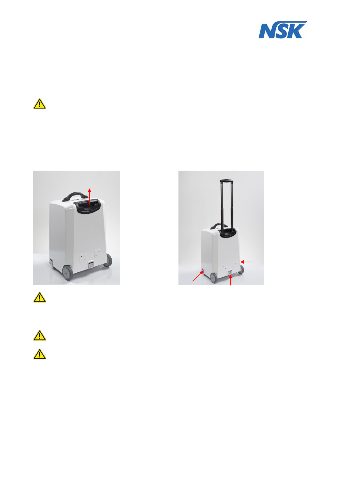
First, the outer packaging (box) must be removed by lifting the device from the box using the handle
attached to the middle of the cover. We recommend that you keep the packaging.
Afterward the telescopic handle can be pulled out and the device can be rolled to the location where it will
be used.
(fig. 1).
There the cover can be removed after opening the three clips (see fig. 2)
fig.1 Unlocking the trolley handle
fig.2 Opening the cover
Check that the device has been set up on a flat and stable surface!
If this is not the case, change the location.
The ventilation slits in the housing MUST NOT be adjusted or covered. Sufficient ventilation of the
device is required to avoid that overheating of internal components occurs.
Attention! Wait before switching-on and using the DENTALONE, until it has adapted to the ambient
temperature (E.g. after a cold night in the car). Note the admissible operation conditions (see section 5).
Attention: in order to avoid the risk of an electric shock this device may only be connected to a supply
network with protective earth.
The device has to be installed in such a way that in case of failure a separation from the supply
network is easily possible by pulling the power plug.
Use only the supplied power cord.
Page 13 of 54
Page 14
8. Use
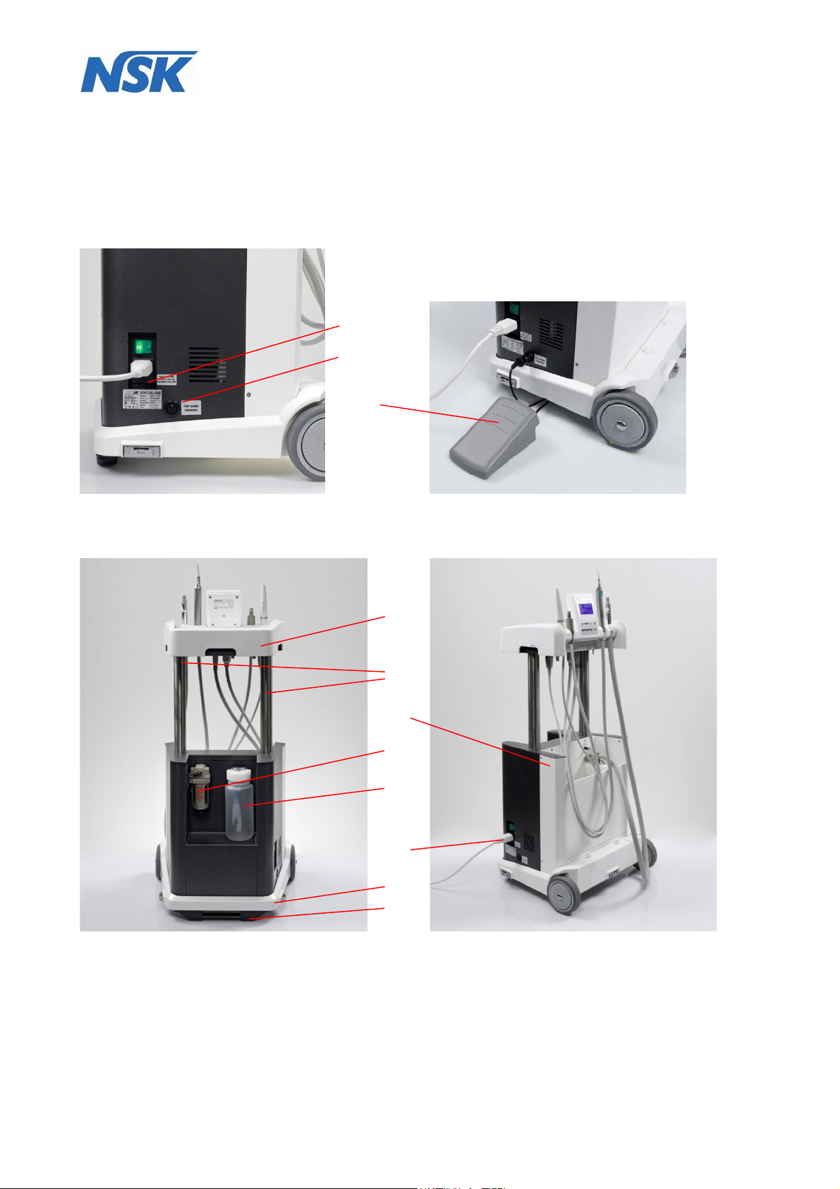
8.1 Description of components
The DENTALONE consists of a base (10) and height-adjustable console (4), which can be pulled out
upwards at two columns (5) and locked.
On the left side of the DENTALONE are the power inlet with the power switch, the fuse holder (1) (fig.3),
and the connector socket for the foot switch (2).
1
2
3
fig.3 fig.4
At the rear of the housing a removable water tank (8) with a capacity of 500 ml is located.
(see fig.5).
4
5
6
7
8
9
10
11
fig.5 fig.6
Page 14 of 54
Page 15
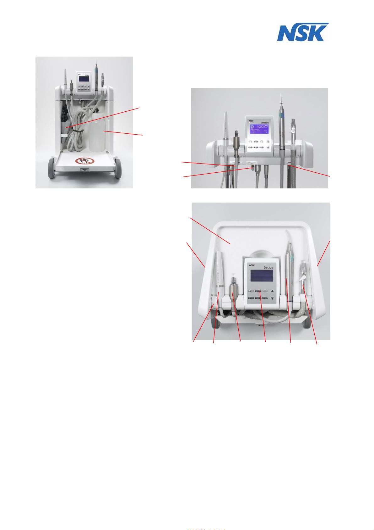
At the front is placed a removable waste water container (12) for suction waste (fig.6).
3
13
14
fig.7 fig.8
1. Power switch / power inlet / safety switch
2. Foot pedal connection
3. Foot pedal
4. Console
5. Pillar guide
6. Housing
7. Compressed air filter
8. Water tank
9. Power cord
10. Base
11. Foot stand with handle
12. Waste water container
13. Spray-adjuster for Scaler
14. Spray-adjuster for Motor
15. Spray ON/OFF Switch
16. Moulded foam insert
17. 2 x electrical unlocking switches for console
18. Instrument holder
19. Ultrasonic Scaler
20. Micro-motor
21. Multifunction control panel
22. Multifunction syringe
23. Saliva ejector
16
17
18
Abb. 9
19
20
21
22
15
17
23
8.2 Preparation / initial operation
First of all the DENTALONE has to be connected to a suitable power supply using the power cord
provided (9) at the power inlet (1).
Please correspondingly consider the regulations for medically used rooms in accordance with DIN VDE
0107.
The instrument tubings and suction hoses have to be taken from the lower storage space and to be
structured in such a way that the loops are not entwined with each other.
Now the power switch (1) at the left side of the device can be switched on. The indicator lamp shows a
green light.
If the DENTALONE is used for the first time or after a long period out of operation, the internal
compressor is working initially until the operating pressure is reached. This process can take up to 20
seconds.
At this stage the console has to be brought into the working position. The procedure is as follows:
In the recessed grips at the left and right side of the console there are unlocking switches (17) and
through the activation of the rocker switches (Fig.10) the console (4) can be electrically unlocked.
(works only when the DENTALONE is turned on and the device has power)
Page 15 of 54
Page 16
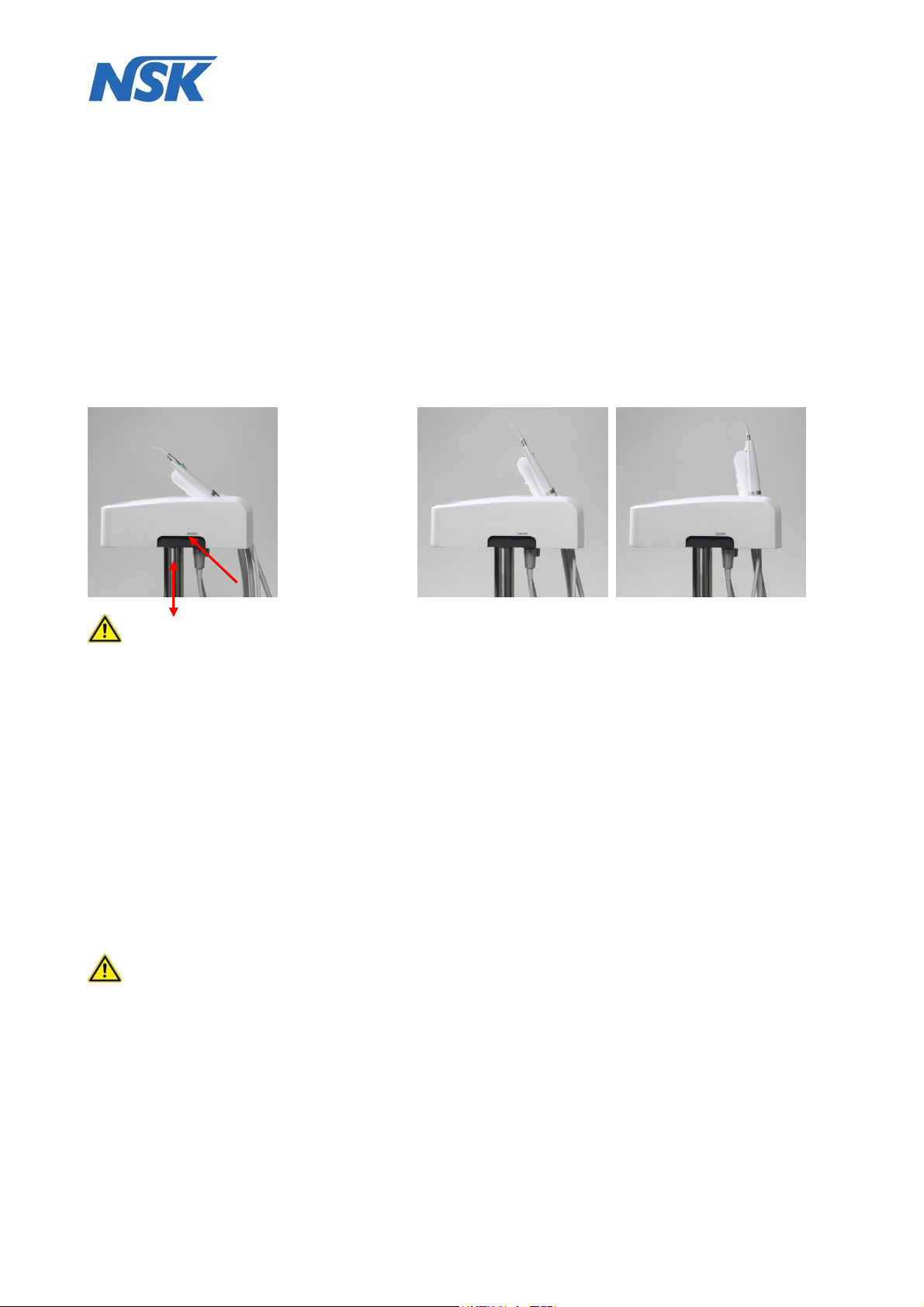
By activating the rocker switches (see illustration (fig.10) and pulling at the recessed grips on both sides
the operating console (4) can manually be moved upwards until it is audibly locked in the working
position, as soon.
After pressing both locking switches (17) and unlocking the console (4) (audible click), the console has to
be lifted within 1.5 seconds to raise it from the lower position into the upper position. Otherwise, the lock
function is activated automatically again. In this case both locking switch (17) must be released again and
process must be repeated. The same applies to lowering the console.
You should remove the moulded foam part (16), which is placed on the console (4) for protecting and
safeguarding the instruments and store it for future transports.
Please check after transport whether the instruments are still placed properly and in the correct order in
the instrument holder (18) (from left to right: Scaler (19); Micro-motor (20); Multifunction syringe (22);
Saliva ejector (23)). Refer to fig.9.
Then swivel the instrument holder (18) by gently pulling on the control panel (21) in a comfortable working
position until it is audibly locked. (fig.10).
There are 2 additional stop positions which facilitate an individual positioning, so that the instruments can
comfortably be taken out and the display i of the control panel (21) can be easily seen (fig.11).
fig.10 fig.11
Please check whether all instruments are completely assembled.
Check your device for completeness in accordance with the delivery notes.
The footswitch (3) is located in a holder mounted side on in the lower part of the device. (fig.7).
Remove the foot switch from its holder and connect it to foot switch socket (2) at the left side of the device
(fig.3 and fig.4).
Before every operation check the device for proper condition.
This concerns the stability of the unit, the two-sided lock in the extended position of the console as well as
the measures described in the following sections of these instructions. All cables, tubings and the suctino
hose should be checked for any damage.
Furthermore , the instrument detection and function of the instruments and also the default settings on
the control panel should be checked. (see section 8.5 and annex A (control panel))
Before the initial operation always check whether there is enough clean water in the water tank and the
suction container (12) is empty.
8.3 Filling the water tank
Before removing of the water tank (8) the DENTALONE has to be switched off at the main switch (1)
or the spray switch (15) has to switch off. Following that any remaining pressure in the system has to be
drained by pressing the venting valve (see fig.12). After that the fresh water tank can be pulled off the
coupling pins by releasing the coupling.
(See fig.13).
Page 16 of 54
Page 17
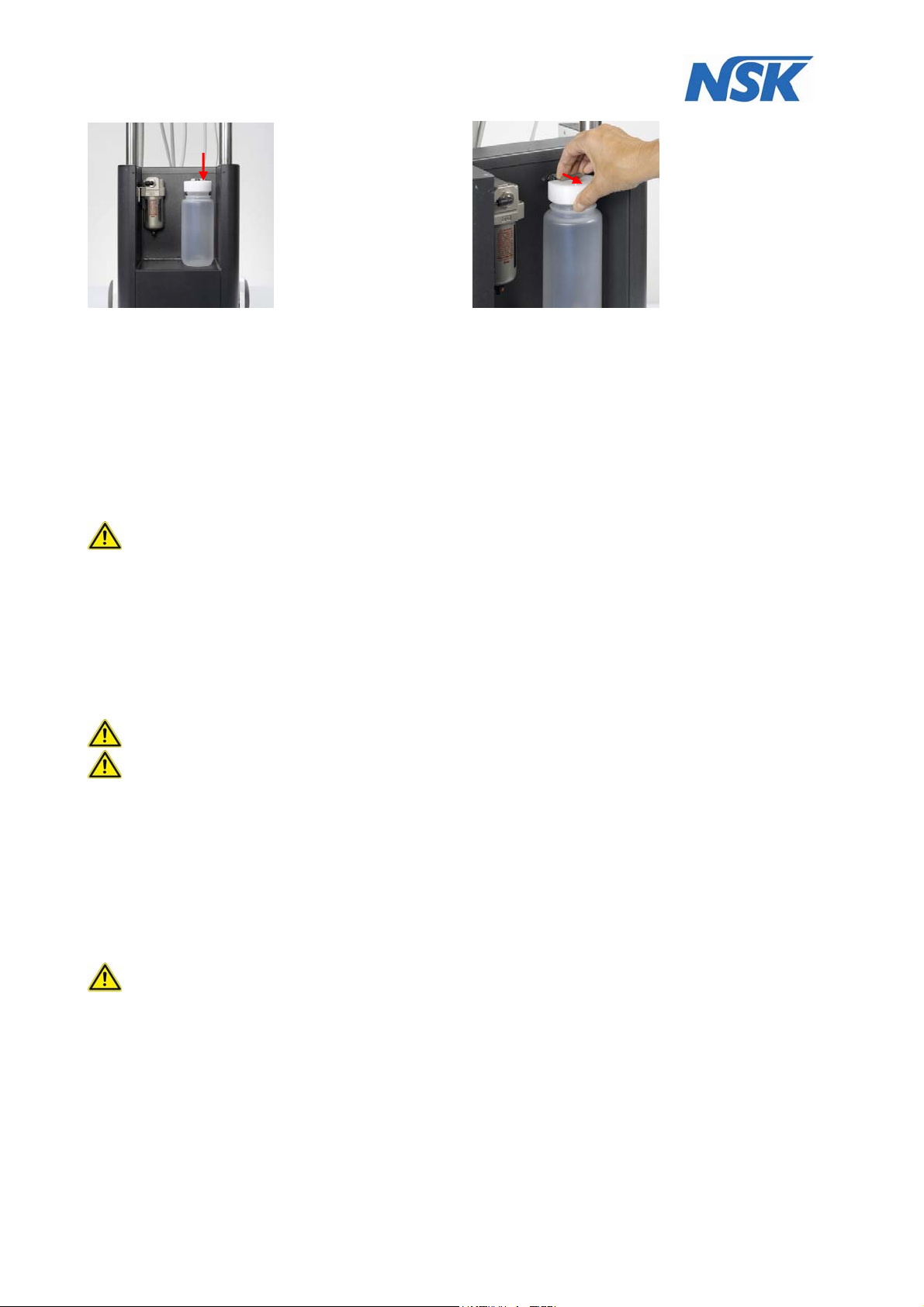
fig.12 fig.13
After unscrewing the screw cap from the bottle any remaining water should be disposed and the container
has to be thoroughly cleaned according in accordance with applicable guidelines.
The water tank (8) should to be disinfected before refilling in accordance with applicable guidelines.
(Refer to section 9.5)
Only use drinking water quality water suitable for dental equipment must be used.
The maximum capacity of the tank is 500 ml
Before closing the bottle also the screw cover has to be cleaned, disinfected and checked for correct
seating of the lid gasket. Please screw the cap hand-tight. Do not overtighten!
Now the water tank can be attached again to the quick release fitting and the Spray switch (15) can be
switched back on.
The compressor will start again to establish the operating pressure
8.4 Completion and arrangement of instruments
During transport of the device all sterile parts of instruments, i.e. Scaler and Scaler Tips, motor
handpiece; the tips of the syringe and the saliva ejector have to be packed separately and must be fitted
again by the user.
See the detailed instructions in section 8.6.and annex B (Scaler) and annex C (Motor).
The instrument holders, as already described in section 8.2, have been located with functionality and
ergonomic operation in mind
The instruments may not swapped between holders, because this would cause malfunctions!
Each day before the first treatment each instrument should be activated 30 seconds in order to rinse
stagnant water in instrument hoses.
Initial operation and practice interruption of more than 24 hours
Before the initial operation and before and after each treatment pause (> 10 hours), disinfection,
cleaning, sterilization has to be carried out! (See section 9.)
Then fill the water tank (8) with fresh drinking water.
Start rinsing process: by switching on the spray function two times in succession for approximately
20 seconds all lines are rinsed with water.
The spray regulators (13) and (14) have to be adjusted to maximum flow setting.
By doing so any disinfection agents in the instrument hoses are thoroughly removed from the hoses.
For safety reasons the device is to be switched off at the power switch (1) before leaving the
surgery.
Page 17 of 54
Page 18

8.5 Operating elements / displays
Control panel:
The operation of the device, which means the setting of defined parameters and operating conditions for
the Varios scaler and NLX micro-motor is carried out by the multi-control panel (21), located in the centre
of the console (4) and the footswitch (3) connected to the device..
Please thoroughly read the instructions for use in annex A before putting the device into operation.
Spray function:
The spray function is switched on and off by means of the rocker switch (15) located at the lower side of
the console.
The spray intensity can separately be adjusted for the NLX micro-motor and the Varios scaler at the
adjusters (13) and (14) at the lower side of the console.
Multifunction syringe:
Regardless of the NLX micro-motor or the Varios scaler the 3 in 1 syringe (22) can be used by activating
their separate buttons on the syringe body,.
Water, air or spray is controlled manually. The syringe will operate as long as the corresponding buttons
are depressed.
Optionally air or water can be discharged. By simultaneously pressing both buttons spray is released.
The discharged water or air flow can be regulated by more or less intense pressure of the buttons.
Footswitch:
The footswitch (3) has to be connected to the corresponding socket at the rear of the left side panel (2)
(fig.3).
By activating the footswitch the respectively active instrument which has been taken from the instrument
holder is switched on, at the end of activation again switched off (Dead-man’s control) and the rotation
speed of the handpiece is controlled. At the same time by activating the footswitch also the instrument
lighting of the active handpiece is switched on or off.
Only the scaler function ON / OFF and the motor with functions ON/ OFF + speed are controlled by the
foot pedal. For multi-function syringe (22) and saliva ejector (23), the foot switch has no function. These
two instruments are simply ready for operation as soon as you take them out of the holder.
8.6 Instruments
All instruments have been developed and constructed for their specific applications. Improper use will
lead to injury, premature wear and tear, destruction of instruments and hazard for the user, patient or third
party.
Please thoroughly read the corresponding instructions for use of the instruments before putting the device
into operation. (Annex A-C)
General information
YOU MUST ONLY USE technically perfect and hygienically cleaned and sterilized handpieces and
contra-angles , scaler and scaler tips (not included in the scope of delivery)
Do not touch rotating instruments. Risk of injury!
Change of drill:
During the treatment pause:
The footswitch may not be activated during the change of drill, because otherwise there is the risk of
injury. For safety reasons the device has to be brought into stand-by position.
During the treatment:
Exchange of the bur or instrument only if the motor has stopped.
Insert drill and abrasive tool as deeply as possible in the chuck system of the instrument
(Please observe the manufacturer's information)
Ensure chuck system is holding bur safely (refer to separate instruction for use of the handpiece)
Bring instruments to full rotation speed before beginning to operate
Avoid tilting or levering; increased danger of breakage
Use of safety glasses is recommended depending on the use
Improper application leads to poor performance and an increased risk
Note the separate operating instructions of the respective instruments in annex A-C
Page 18 of 54
Page 19

Observing the rotation speed recommendations leads to optimum performance.
When exceeding the maximum permissible rotation speed some instruments are prone to can
lead to damage or destruction of instruments
In case of work component diameters which are bigger than the shaft strength strong centrifugal
forces can occur which can lead to deflections of the shaft and/or breakage of the instrument. Do
not exceed the maximum permissible rotation speed.
Please refer to manufacturers instructions to ascertain the maximum permissible rotation speed
of respective instrument.
Avoid excessive pressing forces, because this causes damage of the cutting instruments and
generates excessive heat.
Overheating is caused by excessive pressure on the instrument which leads damage of the pulp.
Excessive pressure can also lead to rough surfaces and. breakages of instruments
To avoid unwanted heat generation a sufficient cooling with an air/water spray (at least 50
ml/min) has to be guaranteed.
Insufficient water cooling causes irreversible damage of the tooth and tissue. In case of failure of
the compressed air generation, the treatment must be stopped immediately.
Blunt burs generate excessive heat and cause damage of the pulp.
Bent instruments not running smoothly have to be disposed of immediately.
Disinfection and sterilisation has to performed in accordance with Manufacturers
recommendations and applicable guidelines.
Before the first use and immediately after each use rotating instruments have to be cleaned and
where appropriate sterilized/autoclaved. Until the first use the instruments should be stored in the
original packaging or transport container at room temperature in a dust- und humidity-protected
manner.
Rotating instruments should be stored hygienically on suitable stands or containers. The same
applies to sterilized instruments and instruments in sterilized packaging. Instruments MUST be
stored in a dust-, humidity-free environment with no risk of recontamination.
In case of non-corrosion resistant instruments disinfection and cleaning agents with corrosion
protection (non-corrosive) have to be used.
The contact with H
(hydrogen peroxide) has to be avoided. Hard metal working components
2O2
are attacked and damaged. Reduction of lifetime.
Avoid temperature over 180°C. Exceeding 180°Cleads to a reduced lifetime.
Rotating instruments made from metal and non rust-proof instruments are attacked by the
thermo-disinfector. This leads to discoloration and a shortened lifetime.
Advices for use, duration of exposure and suitability of disinfection and cleaning substances for
certain types of instruments can be obtained from the manufacturer of the solution.
Store instruments in a dry place.
Protect instruments against sun and heat
8.6.1 Handpieces and contra-angles *)
Please obtain the description, handling as well as maintenance and sterilization advices for the used
instrument from the accompanying documents of the respective instrument.
Only handpieces and contra-angles with ISO E-type fitting can be used.
*) not included in the scope of delivery
8.6.2 Brushless motor Ti-Max NLX-nano
Short description: brushless micro-motor (100-40.000 r/min.) with light, type ISO E with internal
water. Only instruments with ISO E-type fitting can be used.
For further information please refer to annex C (Motor).
Page 19 of 54
Page 20

Safety guidelines
Caution!
Please always consider the safety of the patient when operating the motor (20).
The motor is only provided for dental application by qualified personnel.
The motor only works in conjunction with the control panel (21)
Do not try to disassemble or manipulate the motor.
The user is responsible for regular maintenance and inspection of the motor.
Check the motor outside the mouth for vibration, noises and overheating before
commencing treatment. If any irregularities occur, immediately interrupt the application and
contact your NSK-dealer.
In case of abnormal function of the motor immediately interrupt the application and send it
for repair to your NSK-dealer or NSK service partner.
Do not expose the housing to mechanical impacts. Do not drop the motor. This can lead to a
malfunction.
Do not connect/ remove the motor cable or instrument as long as the motor drive has not
come to a complete standstill.
Do not use the motor under full load for extended periods of time as this will cause it to
overheat.
The time for continuous use should be not more than 3 minutes.
Do not exceed the motor speed recommended by the instrument (Option) manufacturers.
Ensure that the correct speed is set on the control panel.
Before use, always ensure that the instrument is securely located on the motor.
Do not connect / disconnect the instruments during operation.
The motor does not require lubrication
After lubrication leave the handpiece at a suitable location for a certain time. Only place on
the motor when excessive oil has completely drained off. If oil gets into the motor, this leads
to malfunctions of the motor.
Do not autoclave the motor cord (or sterilize with another high temperature procedure).
Do not wipe off, clean or immerse the motor with a disinfectant solution or acid water!
8.6.3 Ultrasonic scaler VARIOS 170 LUX
For further information see the operating instructions of the Ultrasonic Scaler (19)
In Annex B.
Safety instructions
Thoroughly read through these safety guidelines before use and use the instrument only for their
intended purpose and in accordance with the operating instructions.
These displays allow a safe use of the instrument and prevent danger and damages for you and
other persons.
Indicating dangerous situations
Warning!
Do not touch the connections at the end of the scaler cord. This can cause an electric
shock.
If you feel any abnormality such as vibration, heat generation, abnormal noise, etc., prior or
during use, stop immediately.
The Electromagnetic Compatibility (EMC) is described in the operating instructions,
section 4.
Portable and mobile RF communications equipment can affect Electrical Medical equipment.
Do not use RF equipment in close proximity to the product.
USE ONLY NSK genuine tips when using NSK Varios Ultrasonic Scaler (Varios 170 LUX)
problems such as damage, failure and accident of Handpieces resulting from use of Non-
NSK Tips are not included in the warranty. The following are the possible failure that could
happen when using non-NSK tips:
Vibration failure caused by using incompatible tips.E311.
Accidental ingestion of broken tips by the patient.
Damage of thread ridge of handpiece.
Page 20 of 54
Warning!
Page 21

When operating the product always consider safety of the patient.
The scaler is only to be used by qualified personnel
Before using check the vibration of the instrument outside the oral cavity of the patient. If
you determine abnormalities, immediately interrupt the use and contact your NSK-dealer or
authorised service partner.
Avoid hard impacts on the handpiece or dropping the instrument and tips on hard surfaces.
Always work with sufficient coolant water in order to avoid damages of the tooth or an
overheating of the instrument itself.
Tips and Handpiece cannot be cleaned and disinfected with a Thermo-Disinfector.
Sterilize the Tip, Handpiece, and Tip Wrench by autoclaving. Wipe the Handpiece Cord
including the connectors. Disinfect handpiece cable according to the instructions after each
treatment with a VAH* listed, no protein-fixing and Aldehyde-free disinfectants.
If chemical, solvent or antiseptic solution is deposited on this product, immediately wipe it
away. Discoloration or deformation may occur if left.
Do not disassemble or change the handpiece. DO NOT USE on patients with a pacemaker.
DO NOT use near explosive substances or combustible materials. DO NOT use the
instrument on patients anesthetized with nitrous oxide.
Caution!
The instrument may only be used by qualified personnel.
Patient safety MUST ALWAYS have the highest priority.
Before using check the vibration of the instrument outside the oral. If you determine
abnormalities, immediately interrupt the use and contact your NSK-dealer or an authorised
service partner
Do not exceed the recommended performance area for the applied tools, because it could
not only damage the tooth but also the tip.
Do not contact ceramic prostheses during the treatment, because it could damage the
prostheses and/or tip.
DO NOT contact ceramic or metal crowns except when removing. The tip could break and
fall out.
Never sharpen or bend tips. Tips could be damaged and not generate sufficient vibrations.
Use tip guide to check tip is fit for purpose.
Do not directly use the tip on the gums, mucous membrane or skin. This implies the danger
of injuries or combustions.
The tip is subject to general wear and tear and natural material fatigue, which will result in
reduced performance. In this case the tip should be replaced.
. Tips MUST NOT be changed while the scaler is in operation.
Always use NSK tip wrench to carefully attach the tip Otherwise only a reduced vibration
could be produced.
Before use check the screw thread of the tip for potential contaminations and clean if
contaminated.
Use only NSK scaler tips, because scaler perforance may be affected or handpiece may be
damaged by using tips NOT made by NSK. For more information refer to annex B, section
B5 and B6.
Do not sterilize the instrument with ultraviolet radiation, because the handpiece may change
colour due to this.
Unplug the handpiece at the hose coupling only after the tip has been removed. (Risk of
injury)
Caution!
The user is responsible for a constant functional supervision, maintenance and inspection of
the scaler
For the storage of the instrument the following limits apply: air temperature -10…60°Cr
humidity 10…85% and atmospheric pressure 500…1060hPa
Air MUST be free of any contamination, sulphur dioxide or salt.
To disconnect the handpiece from the handpiece cord for sterilization and/or cleaning, pull
gently apart by holding the handpiece body in hand and the connector on the handpiece
cord in the other hand. Pull along the long axis of the handpiece and DO NOT twist.
* Association for Applied Hygiene (VAH)
Page 21 of 54
Page 22

Warning! DO NOT touch the connections at the end of the scaler cord as this can cause an electric
shock.
Caution! Make sure that the scaler tip is removed, before you disconnect the handpiece to avoid
injury.
To disconnect the handpiece from the handpiece cord, pull gently apart by holding the handpiece body in
hand and the connector on the handpiece cord in the other hand.
8.6.4 Multifunction syringe
Short description
The Multifunction syringe (22) is a device exclusively designed for the dental sector. It serves to blow in
air and water, individually or as spray, in order to clean and dry the operating field.
Handle
Button
Screw
fig.14 fig.15
Characteristic features
Ergonomic aspects were decisive for the choice of this Multifunction syringe for Dentalone.
This Multifunction syringe is easy to use, simple to clean and sterilize.
An LED-light positioned in the grip sleeve improves the visibility in the treatment area. Both the Cannula
and the handle are easy to dismantle, perfect to disinfect and sterilize in an autoclave at 135 ° C i.e. NSK
iClave.
Use
For water only press the left key
For air only press the right key
For water-air mixture/spray press both keys at the same time
The LED light is automatically activated when you take the syringe out of the holder.
Cleaning and sterilization
To constantly guarantee maximum hygiene, you should clean and sterilize the multifunction syringe tip
after each treatment. To take the syringe apart, please follow these instructions:
Remove the syringe cannula by loosening the screw (fig.14)
To remove the complete syringe handle, push the button at the lower end of the handle in axial
direction upwards. (fig.14)
Wipe off potential contaminations with a clean cloth.
The parts have to be sterilized in a steam autoclave at 134°C at least 3 minutes ie.e NSK iClave
Maintenance
Except the described cleaning and sterilization no additional maintenance is required for the syringe. DO
NOT lubricate the multifunction syringe as this will cause irreparable damage.
Cannula
Page 22 of 54
Page 23

8.6.5 Suction
The suction system offers the prerequisite for relaxed and ergonomic working without permanent
interruptions due to the swallowing reflex of the patient.
The saliva ejector (23) allows the use of interchangeable flexible saliva ejector tips (consumable material)
or autoclavable tips (size 6 mm or ¼”).
The suction is automatically switched on as soon as the suction hose is taken from the instrument holder
and vice versa the suction is switched off, when the suction hose is put back in the in the holder.
Please note the position of the lever on the suction handpiece.
Lever position forwards = closed
Lever position backwards = open
The suction is automatically switched off, as well, when the waste water reservoir (12) is full and has to
be emptied.
The waste reservoir has a maximum volume of 1 litre It is located on the front or the unit. (See section 8.1
– fig.7)
Cleaning:
Before disconnecting the reservoir the saliva ejector has to be emptied, by holding the saliva ejector
as high as possible and by doing so slightly stretching the suction tubing to allow any residual liquid
to drain out of the tubing into the reservoir.
Pull out the plug of the filling level sensor socket! (fig.16).
After that the reservoir has to be released from the connector by pressing the release lever.
Connector “Level-Sensor”
unlocking lever on quick release connector
suction tube connector
fig.16
After that the reservoir can be removed from the connector and be emptied. To remove lid unscrew from
the reservoir and empty content into an amalgam separator, waster container or sewer system in
accordance with applicable regulations. Additional waste water reservoir containers with lids are available
as an accessory.
Before reuse the reservoir should be cleaned (see also section 9).
After cleaning and screwing the lid back on the reservoir can be placed back on the quick release
connector ready to be used again. Please make sure it is securely held in place by listening out for
noticeable locking click indicating that it is securely in place.
ALWAYS check the safe and secure fastening of the reservoir before use
Re-insert the plug of the level sensor in the contact socket (level sensor).
A filter is installed in the front part of the saliva ejector. This is accessible by careful removing the
rubber adapter for the suction nozzle.
Clogging the strainer may cause a malfunction or power reduction of extraction. Therefore, the strainer
should be checked after each treatment and daily cleaned.
Page 23 of 54
Page 24

9. Cleaning, maintenance, disinfection and sterilization
9.1. General
When cleaning the Dentalone protective gloves MUST be worn at all times for health and safety
compliance.
Objects which cannot be sterilized and disinfected MUST NOT be handled with the same gloves.
When interrupting cleaning process the gloves have to be taken off.
A treatment area is defined as an area where the recommendations regarding the hygiene
requirements in the reprocessing of medical devices of the Division of Hospital Hygiene,
Infection Prevention and Control of the Robert Koch-Institu te and The Federal Institute for
Drugs and Medical Devices apply.
Cleaning intervals:
Between patients
Rinse the water tank and fill with fresh drinking quality water
Connect suction hose and saliva ejector to the waste container and then rinse by sucking
approximately 0.2 litre drinking water.
Change the saliva ejector cannula consumables), the multi-function syringe tip (Autoclavable) and
scaler including scaler tip.
Disinfection of all parts, which were touched during the treatment or came into contact with the
patient.
These include especially
hose, coupling piece and saliva handpiece, console upper part with instrument holder,
multifunction syringe, scaler, motor, patient chair.
At the end of the working day
All of the aforementioned items as between patients
Sterilisation of the water tank (the water tank cap only to clean and disinfect!).
Clean and disinfect suction handpiece, suction hose and waste water collection tank including cap
with disinfectant solutions in accordance with the manufacturer's instructions.
Disassemble saliva ejector and suction hose attachment, wash and lay in disinfection solution
overnight.
Clean sieve of suction hose.
Cleaning and disinfection of the unit
Once per week
All of the aforementioned steps as per the end of the working day procedures
Autoclaving of the water tanks and the waste water collection container (clean and disinfect the caps
– as the caps are not autoclavable!)
Page 24 of 54
Page 25

9.2. Disinfection, cleaning and sterilization of instruments and handpieces
Contaminated instruments have to be changed between patients to be cleaned, disinfected and
sterilized in accordance with applicable guidelines following the manufacturer’s instructions.
For disinfection and sterilization the selected procedure MUST be suitable for the respective
instrument, you will find relevant information also in the detailed operating instructions for the
micro-motor, contra-angles,handpieces and ultrasonic scaler in annex B und C.
Before the first use and immediately after each use rotating instruments have to be cleaned and
sterilized. Until the first use the storage has to be conducted in the original package at room
temperature in a dust- und humidity-protected manner.
Rotating instruments should be stored on hygienically maintained stands, autoclaving pouches or
other suitable containers. The same applies to sterilized instruments and instruments in sterile
packaging. The storage has to be in a dust-, humidity- and recontamination-protected environment.
In case of non-corrosion protected instruments disinfection and cleaning agents with corrosion
protection have to be applied.
The contact with H
metal working components invalidate the product warranty and shorten the product life.
Avoid temperature over 180°C as this will reduce the product’s life.
Rotating instruments out of hard metal and non rust-proof instruments are attacked by the thermo-
disinfector. This leads to discoloration and a short lifetime.
Always refer to manufacturer’s instructions before using any cleaning or disinfecting solutions.
(hydrogen peroxide) has to be avoided as this will attack and damage hard
2O2
9.3. Cleaning and sterilization of drills and abrasive tools
Drills and abrasive tools have to be cleaned, disinfected and sterilized professionally. Suitable
cleaning and disinfection agents can be obtained from specialist dental suppliers. Instructions for use
have to be strictly followed.
9.4. Cleaning of surfaces which cannot be sterilized
(Unit, trays, etc.)
General procedure:
Disinfect by wiping with a cloth which is soaked in disinfectant solution. Mechanical wiping movement
with a wet, however not dripping cloth is essential. Do not wipe with a dry cloth afterwards.
Painted surfaces and all metal parts can be wiped with mild cleaning and disinfection agents. Please only
use ammonium chloride-free agents, because ammonium chloride would destroy the paintwork in the
long run!
9.5. Water pipes and water tank
After longer periods when the unit has not been used (especially in the morning before first use) all
tubings, pipes and hoses of the unit.
The water tank (without screw cap) has to be autoclaved at 121°C once a day.
The lid of the water tank should be disinfected with VAH listed disinfectants because it cannot be
autoclaved.
For disinfection and to prevent the formation of organic film it is recommended to flush all tubings,
pipes and hoses regularly with suitable solutions (Please refer to section 9.7)
Afterwards rinse thoroughly by running each instrument twice for at least 20 seconds with the water
spray function activated The spray controls (13) and (14) have to be turned on maximum flow. Thus,
the remains of cleaning and disinfectant are rinsed from the hoses.
Remember that the cap of the water tank MUST NOT be autoclaved!
Page 25 of 54
Page 26

9.6. Suction system
Wipe suction hose between patients with a disinfectant wipe.
To avoid blockages flush hose especially following procedures with bleeding with cold water but at
least 4 to 6 times per day Attach suction hose to the waste water container (12) and rinse.
At the end of the day’s sessions flush suction hose as per manufacturer’s instructions.
The waste water collection reservoir (wide neck glass bottle) has to be thoroughly cleaned after
emptying and, if necessary, to be autoclaved at 121 °C (except the screw cap which is NOT
autoclavable).
The lid of the waste water reservoir MUST NOT be autoclaved!
9.7. Recommended disinfection and cleaning agent
BILPRON Agent for operating water disinfection
ALPRON Agent for water treatment
BIOTEST plus Agent to verify the bacterial load of liquids and surfaces
AlproJet-DD or -D Highly effective concentrate for daily cleaning of suction systems
AlproJet-W Highly effective concentrate for the weekly cleaning of suction systems
Always follow the instructions of the manufacturer of disinfectants and cleaning solutions.
10. Maintenance
It is recommended to maintain the DENTALONE according to the suggested intervals (see below).
Maintenance and repair may only be carried out by authorized personnel by an appointed dealer or the
manufacturer.
It is not permitted under any circumstances for unauthorized persons to open and interfere with the
device.
Changes and repairs carried out by unauthorized persons invalidate the manufacturer’s warranty and
liability.
In addition to the inspection and functional examination during regular maintenance of the device an
examination according to DIN VDE 0702/0751 has to be carried out.
All parts subject to normal wear and tear have to be replaced as required and are not covered by the
warranty.
Advice: For the disposal of packaging, accessories and also the device you MUST COMPLY with
applicable regulations!
10.1. Regular maintenance works
Scope and intervals of the safety-technical checks should be in accordance with country-specific
regulations.
Recommended are:
At least once every 12 months the below mentioned safety-technical checks have to be carried out under
consideration of DIN VDE 0750 and DIN VDE 0751:
- Visual control of the device and accessories, examination of the protective earthing according to DIN
VDE 0751, equivalent leakage current measurement according to DIN VDE 0751.
- Functional checks of the device under consideration of accompanying documents.
It is recommended to keep a log book, in which the examination results of the safety-technical checks are
documented.
Clean liquid container regularly, if necessary, de-scale and autoclave at 121°C.
10.2. Maintenance intervals
Daily maintenance (by the user)
The fulfilment of requirements for hygiene and the maintenance of efficiency of the device is guaranteed
by carefully observing the information for disinfection, cleaning and maintenance of the instruments.
Before the first treatment flush all tubings and hoses pipes for approximately 30 seconds by operating
all outlets. While doing this, the spray controls (9) and (10) for motor and scaler have to be adjusted
on maximum flow.
Clean and maintain handpieces and contra-angles in accordance with manufacturer’s guidelines.
Important: observe exactly the maintenance instructions of the instruments under section 8.6 and 9.
Page 26 of 54
Page 27

Instrument tubings CANNOT be cleaned in the thermo disinfector and MUST NOT be exposed to
temperatures exceeding 40 °C maximum.
Annual maintenance (by authorised personnel)
Basic cleaning of the water lines:
A basic cleaning of the water lines to remove biofilm is necessary for the treatment unit which has been in
operation for more than one year. This has to be carried out by an authorised service technician.
Remove instruments from micro-motor and scaler handpiece, so that the water channels in these
instruments do not get blocked as a result of the cleaning process.
Control:
Within the examination of the treatment unit it has to be inspected:
control of function and performance
examination of delivery volume of the water
Visual Control
- Integrity of the housing
- Integrity of hoses, fuses and the power connection cable
- Labels, symbols, indicator lamps
- tightness of water and air channels
- Instrument wear
- Existence of the operation manual
10.3. Maintenance works at the compressed air reservoir
The compressed air filter (7) is located on the left side next to the water tank. In regular intervals during
cleaning and maintenance drain condensate which may have accumulated in the filter.
The drain valve MUST ONLY be operated when the unit is turned OFF, (fig.17) Start by placing an
absorbent cloth under the drainage valve and wipe the housing thoroughly dry afterwards.
fig.. 17
10.4. Replacing the hand piece cords
Should the exchange of one of the motor- or hand piece cords be required, please follow the below steps:
Switch off the unit on the main switch.
After that, release any remaining pressure in the water tank by pushing the release vent. (fig. 12) and
remove the tank..
Unscrew the defective hose from the unit below the console and then disconnect it carefully (gently
pulling downwards).
It is possible that some remaining fluids may drip from the connections.
(please keep an absorbent cloth for drying to hand)
For disconnecting the cord on the scaler or micro-motor please refer to the related sections in annex
B and C.
When replacing the multifunction syringe, any remaining pressure and water in the
system will escape from the open hose. (please keep an absorbent cloth for drying to hand)
The multi-function syringe together with the hose can be separated from the unit and completely
replaced together with the hose or seperately
The unit may only be put into operation if all outlets are properly connected.
Please check that the connectors are tight after they have been changed.
In case of any leaks please liaise with manufacturer appointed dealer or the manufacturer.
Page 27 of 54
Page 28

11. Malfunctions and trouble-shooting
11.1. Fault diagnosis
Please see below information for help should you come across any issues. In case problems cannot be
resolved please contact manufacturer appointed dealer or the manufacturer.
Malfunction Search for problem Cause Measures
Please check power cable
Device does not
work
Main switch does not
light-up
No power from mains
electricity
connection / check device
fuses / if necessary, check
socket
Micro-motor
does not work,
when taken
from the holder
Spray function
does not work
Suction does not
work or only with
restricted
performance
Page 28 of 54
Main switch light works
but no display in the
operating part
Control panel displays
fault code – see
operating instructions,
annex A
Control panel displays
still in the previous status
Check filling level of the
water tank
Check the spray switch
Check by activating the
vent valve, if air escapes
at activation
Check Spray adjuster
Check the lever on the
suction handpiece
Check Sieve Sieve is clogged
Check the screw cap
Check the O-ring seals
on the coupling plug from
the tank and the suction
hose
Check filling level of the
waste container
missing signal from the
filling level sensor
Check the floating body
of the filling level sensor
Possibly power supply
defect, internal device
fault
Motor is not
connected
Foot pedal not
connected or defective Connect or check footswitch
Faulty contra-angle or
handpiece (blocked or
ceased up)
Optical detection
sensor in holder is dirty
Defect of electronics
No water Fill water tank
Spray switch not
activated
No pressure built-up in
the water tank,
because either screw
cap is not closed tightly
or seal is missing
Spray adjuster was
closed
Lever at "closed"
position
Lid isn’t tightly screwed
on; or missing seal.
Effect: vacuum is not
building up
Seals missing or
damaged
Waste container full Empty waste container
filling level sensor isn’t
connected on the unit
floating body sluggish
and remains in the
upper position
Send device for repair, no
self-help possible
Check connection of the
handpiece to the device
Check the handpiece/contraangle and the chuck locking
system
Clean the optical sensors
with a cotton swab
Send device to repair, no
self-help possible
Switch on spray selector
switch
Screw the cap tightly on the
water tank and/or clean the
seal
Adjust to the desired volume
Move lever to
"open" position
clean, or replace if
necessary
Check the seal ring, clean
and screw the cap tightly.
Replace the seals
Check the connection
(fig. 15)
Clean the guiding surfaces
and check for smooth
operation
Page 29

Electric
unlocking of
console does
not work
11.2. Fault signals
Signal Description Measure
Main switch does not
light
Locking mechanism
jammed
Only one of the
unlocking switches
(one side of the
console) is activated
Internal electric
functional disturbance
No voltage
Relieve the plunger of the
locking mechanism by
slightly lifting the console
during activation of the
unlocking button
De-press the unlocking
button on both sides of the
console
Use manual emergency
unlocking (section 11.4),
send device for repair to
NSK service partner
Please check power cable
connection
Acoustic signal
permanent
Acoustic signal
alternate
Error code on the
Control Panel
Device temperature < 10 °C
(outside of the limits)
Device temperature > 70 °C
(outside of the limits)
Refer to instruction of use for the
control panel in annex A
Move the machine into a warmer
environment
Move the machine into a cooler
environment (treatment break)
Refer to instruction of use for the
control panel in annex A
11.3. Change of fuse
Attention! Only carry out change of fuse while unit is disconnected from the mains electricity
supply. Hazard of electric shock! Hazard of electric shock!
The fuse box is located at the side of the power inlet between the main switch and the power socket.
Before changing the fuse always disconnect the power cable from the power socket!
For opening the fuse box you require a flat screwdriver by which you carefully take out the link.
Attention! Only use fuses with the correct rating.
After that push back the fuse in the holder until it is securely held.
Page 29 of 54
Page 30

11.4 Manual unlocking the console
Attention! Please only use this mechanical unlocking option of the console in case of defect or
power failure.
For manual emergency unlocking remove the cover cap at the housing. (fig.18)
Then turn the slotted screw with a screwdriver by approximately ¼ turn clockwise until the console is
unlocked (fig.19), while a second person gently pushes the console downwards.
The locking in the transport position is automatically carried out.
fig.18 fig.19
12. Disposal advices
The device and its packaging were made from materials which can be recycled. This reduces the waste
and protects the environment.
Discard the packaging separately for recycling in accordance with local recycling options.
Devices that are marked with this symbol must not be disposed as household waste!
You are legally obliged to dispose old devices separately from the household waste.
(European Directive 2002/96/EC) Get free information about the disposal of your product
from your NSK dealer.
WEEE-Reg.-No. DE 72356056
Page 30 of 54
Page 31

13. Technical data
1
Mechanical data
Dimensions including cover: (Heightxwidthxdept) 580 x 415 x 365 mm
Dimension without cover in operating position:
770 x 405 x 350
(Heightxwidthxdept)
Weight: (including cover) 19,5 Kg
Protection type (covered): IP32 nach EN 60529
Protection type without cover: IP30 nach EN 60529
Electrical data
Nominal voltage: 100 - 240 V~ 50/60 Hz
Power consumption: max. 400 VA on 230 VAC
Device fuse: 2x T4,0 AL / 250 V
Protection in the installation: 16 A idle (e.g. circuit breaker with B-
character)
Protection class: I according DIN EN 61140
Classification according to MDD 93/42/EWG annex IX:
IIa
Operating data
Operation mode continuous
Noise level < 58 dB
Capacity of Water Tank 500 ml
Capacity of Waste Container 1000 ml
Suction power of vacuum pump (max.) 11 l/min air; 78% vacuum
Compressor– air pressure (max.) 3,0 bar
Water consumption for spray >50 ml / min
Cooling air for Motor >6,5Nl / min
Motor speed 1000 – 40000 min
-
Motor torque Max. 3,4 N cm
Operating temperature +15 … +40 °C
Life time 5 years
Storage and transport conditions
Temperature area -10 …+60 °C
Relative air humidity, non-condensing, no tropical
protection
10…85%
Air pressure 500 – 1060 mbar
Page 31 of 54
Page 32

K O N F O R M I T Ä T S E R K L Ä R U N G
D E C L A R A T I O N O F C O N F O R M I T Y
Wir
We
Hersteller / Manufacturer:
NSK WT GmbH
Portitzer Straße 69 d
D-04425 Taucha
Germany
erklären in eigener Verantwortung, dass das Medizinprodukt
declare on our own responsibility that the medical device
Artikel-Nr. / Article number: 9070
allen relevanten Anforderungen der Richtlinie 93/42/EWG und
der Richtlinie 2006/42/EG entspricht.
meets all the provisions of the Directive 93/42/EEC and Directive 2006/42/EC which apply to him
Angewendete Normen
Applied standards
(Liste der Angewendeten Normen / List of applied standards)
Gesetz über Medizinprodukte (Medizinproduktegesetz MPG)
EN 60601-1 (Gerätesicherheit)
EN 60601-1-2 (EMV)
EN 60601-1-6 (Gebrauchstauglichkeit, Ergonomie)
DIN EN ISO 14971 (Risikomanagement)
Benannte Stelle
Notified Body
BSI Group Deutschland GmbH
Eastgate
Hanauer Landstraße 115
60314 Frankfurt
Kenn-Nummer / Registration Number. CE 595189
Konformitätsbewertungsverfahren Anhang II.3 93/42/EWG
Diese Erklärung gilt für alle oben genannten Produkte, die während des Jahres 2014 und 2015
hergestellt sind und für die eine interne Freigabe vorliegt.
This declaration applies to all above mentioned devices manufactured in 2014 and 2015 for which an
internal release was given.
Die Technischen Unterlagen werden beim Hersteller aufbewahrt.
The technical data are kept by the manufacturer.
Taucha, den
Unterschrift und Angabe der Funktion
Signature and function of the signing person __________________________
Dieter Bauch
General Manager NSK WT GmbH
Page 32 of 54
Page 33

Annex A
Operation manual Multi-control panel
Please read this Operation Manual carefully before use.
A1. General information
Precautions for the handling and operation
Read these safety cautions thoroughly before use and operate for their intended purpose according
to this manual.
Connect only NLXnano-Motors. Do not connect any other motor!
These indicators will show you how to operate the product safely and prevent danger to you or
others. They are classified by degree and/or severity of danger. All contents relating to safety should
be observed.
Classification Degree and severity of danger or damage
Danger
Warning
Caution
Notice
Provides an instruction where death or the instructions may occur.
Provides an instruction where personal injury or physical damage may
occur.
Provides an instruction where minor to medium injury or physical damage
may occur.
Provides an instruction that should be observed for safety reasons.
Danger
Do not attempt to disassemble the product or tamper with the mechanism, it may cause an
electric shock or fire.
Warning
Do not use the productfor implant surgery.
The product is designed only for clinical dental use by qualified personnel.
Caution
The multi-control panel is not water proof and should not be exposed to water.
Do not use the multi-control panel as a handle when you want to move the dental unit.
Do not pull the instrument cords and suction tubing with an excessive force.
Be sure to press the buttons with a finger.
When operating always consider the safety of the patient.
Should the product function abnormally, cancel the operation immediately and send it to your
NSK-dealer for repair.
Care should be taken not to place the motor cord near a gas burner. Never attempt to repair
a burnt motor cord. Always replace damaged cords with a new one.
Do not exceed the drive motor speed recommended the bur/file manufacturers.
Ensure the gear ratio on the display and gear ratio of the handpiece match.
Please ensure that rotation speed range is set correctly.
Don’t use or leave the product in a high–temperature environment such as under strong
direct sunlight, by a fire or near a radiator as this may cause a malfunction for inner circuit or
sudden heat generation.
Page 33 of 54
Page 34

Summary of user setting menu
Motor
The following menus will be displayed on the LCD screen:
1. Language ► English
2. Gear ratio Espanol
3. Lamp Italiano
4. Endo mode Francais
5. Air Deutsch
6. Endo alert
7. Others
8. Version
1. Language ►
2. Gear ratio Gear ratio 1 ► 1 – 20 : 1 – 5 *
3. Lamp Gear ratio 2 ► 1 – 20 : 1 – 5 *
4. Endo mode
5. Air
6. Endo alert
7. Others
8. Version
* Adjustable range
1. Language
2. Gear ratio
3. Lamp ► On / Off ► On / Off
4. Endo mode Intensity ► 1.6 – 3.6 V *
5. Air Delay timer 1.0 – 5.0 sec *
6. Endo alert
7. Others
8. Version
* Adjustable range
1. Language
2. Gear ratio
3. Lamp
4. Endo mode ► Display setting ► Ncm
5. Air mm
6. Endo alert %
7. Others Auto REV time ► 0.3 – 1.0 sec *
8. Version Auto FWD time ► 1.0 – 3.0 sec *
* Adjustable range
“Endo mode” setting is not reflected in the case of the NLX nano motor
1. Language
2. Gear ratio
3. Lamp
4. Endo mode I
5. Air ► Display setting ► psi
6. Endo alert bar
7. Others MPa
8. Version Motor MIN pressure ► 0.03 – 0.10 MPa *
Motor MAX pressure ► 0.20 – 0.40 MPa *
Page 34 of 54
Page 35

1. Language
2. Gear ratio
3. Lamp
4. Endo mode I
5. Air
6. Endo alert ► Endo mode alert ► On / Off
7. Others Alert setting 1 ► 40 – 80 %*
8. Version Alert setting 2 ► 80 – 100 % *
REV alert ► On / Off
* Adjustable range
“Endo mode” setting is not reflected in the case of the NLXnano motor
1. Language
2. Gear ratio
3. Lamp
4. Endo mode I
5. Air
6. Endo alert
7. Others ► LCD contrast ► –2, –1, 0, +1, +2
8. Version Backlight timer ► 1 – 30 min or ∞ *
Acceleration time ► 0.5 – 3.0 sec *
Default setting ► No / Yes
* Adjustable range
1. Language
2. Gear ratio
3. Lamp
4. Endo mode I
5. Air
6. Endo alert
7. Others
8. Version ► LCD XXXX
► NLX XXXX
► VA170 XXXX
Scaler
In the case of connected to the Varios 170 this menu is displayed at the setup:
1.Version ► LCD XXXX
VA170 XXXX
NLX XXXX
A2. Features
Integrated System of Electric Micromotor (NLX BF) and Multi Function Ultrasonic Scaler (Varios 170)
can be controlled with the multi-control panel.
User settings are achieved via the LCD graphical user interface.
Visual identification of graphics on the multi-control display is possible even during operation of the
handpiece.
The multi-control panel allows up to 8 custom programs for your exacting needs (motor only).
The multi-control panel supports 5 languages (English, Espanol, Italiano, Francais and Deutsch).
Page 35 of 54
Page 36

(UP)
(
A3. Description of the user interface
Display
MODE-key
FWD/REV-key
ESC-key
SET UP-key
SELECT-key
-key
ENT/SAVE-key
DOWN)-key
A4. Start-up
When turning the power ON, the name of connected instruments will be displayed for about 3 seconds
along with a beep tone. Then, the LCD display will switch to operating screen automatically
When turning the power on and simultaneously push the foot control, the display of the multi- control
display will show the error message with „ Release Foot Pedal“ until a beep is heard.
The error message will disappear when foot controls is released.
.
A5. Description of the display
A5.1. MOTOR
While the display shows the fig.1, you can control a motor by pressing the foot control pedal.
Rotation display (fig.1):
When the motor is stopping, the display shows the maximum rotation speed. When the Motor is
rotating, the display shows the actual rotation speed.
When the motor stops, the display shows ”0” on the display then turn to the maximum rotation
speed originally selected.
Forward Mode: Motor turns clockwise
Reverse Mode: Motor turns counter clockwise.
Rotation speed display (fig.1)
The display shows rotation speed you selected. While the motor is rotating, the
actual rotation speed will show on the display
Page 36 of 54
Page 37

SET VALUE display:
The pre–programmed maximum rotation speed is indicated on the display. The icon will go
off while the motor is rotating. While the motor is rotating
for 1 second.
Program number display: (fig.1)
The program number you selected will be displayed. For detailed program setting, refer to
section A7Useful functions”.
Gear ratio display: (fig.1)
The preset gear ratio is displayed. A total of 10 different gear ratios can be selected.
8 gear ratios are default and cannot be changed.
2 gear ratios are for customized setting by users. For detailed gear ratio setting, refer to
section A6. „Settings".
A5.2. SCALER
the speed icon appears
While the display shows the fig. 2, you can control the ultrasonic scaler by pressing the foot control.
Ultrasonic Vibration display: (fig.2)
When the scaler is vibrating, vibration icon will be displayed.
Vibration Mode display: (fig.2)
Power Level display: (fig.2)
Selected ultrasonic mode is displayed. (Perio, Endo or General)
Selected ultrasonic power level is displayed. (POWER 0 – 10)
A5.3. Selection of the instrument
The selection of the instrument is done automatically by removing the respective instrument (scaler or
motor) out of the instrument holder.
Page 37 of 54
Page 38

A6. Settings
A6.1. MOTOR
Functions you can set while the motor is rotating: Maximum rotation speed, rotation direction.
Functions you can set while the motor is stopping: maximum rotation speed, rotation direction,
gear ratio, program (PRG).
Speed setting
Press the ▲ / ▼ key to set your desired speed in the motor function display.
Speed Range: 1,000 – 40,000 min
Notice
Speed display changes faster as you press and hold the ▲/▼ key
Gear ratio setting
A maximum of 10 different gear ratios can be set.
8 are fixed default settings, 2 are for free settings.
- Press SELECT key until ‘Gear ratio’ on the display blinks at the normal display.
- Press ▲ / ▼ keys to choose an appropriate Gear ratio.
- Press and hold ENT/SAVE key for 3 seconds or longer to save the set Gear ratio.
Notice
The turn by ▲/▼ key is shown below
▲key
-1
▼ key
*Gear ratio 1 und 2 only displayed, when you set them in user setting menu. For user setting menu, refer to section A9. „Other Settings".
Rotation Direction setting
To select the motor forward rotation, press FWD/REV key, until “F” appears at the normal display.
To select the motor reverse rotation, press FWD/REV key, until “R” appears at the normal display.
A6.2. SCALER
Treatment mode setting:
Use MODE key to select the different treatment modes at the ultrasonic scaler display.
Press MODE key, “Perio”, “Endo” and “General” modes will be displayed as you press the key.
Power level setting:
Use ▲/ ▼key to select the power level at the normal display.
Press ▲ key for increase, press ▼ key for decrease.(Power 0 to 10).
A7. Useful functions
A7.1. MOTOR
Up to 8 customized settings are available with the following selections:
Maximum rotation speed
Rotation direction
Gear ratio
Program selection
:
1) Press SELECT key, until program number is displayed blinks at the motor function display.
2) Press ▲ /▼ key to select the program number that you want to use.
3) Press ENT/SAVE key for 3 seconds or longer, the selection is completed.
Notice
When the program you selected is modified, the colour of „PRG“ will inverse
Page 38 of 54
Page 39

A8. Error-Codes
A8.1. MOTOR
The system incorporates an automatic diagnosis feature that can help to diagnose the cause of a
problem in the event of failure mode. When the system has failed, the display will show the “E–**”
code and message. Details of each error code are listed below.
Error
Code
E–00 Over setting torque
E–01 Over current (Soft1) Too much torque is loaded Release the foot control
E–02 Over current (Soft2) Abnormal electric current
E–03 Fault error Motor driver is over current Contact NSK dealer
E–04 Overheat Motor is overused Leave the motor until it has cooled down
E–05 Over input voltage Excess voltage Contact NSK dealer
E–06 Over lamp voltage Lamp circuit over voltage Contact NSK dealer
E–07 Residual voltage error Output circuit error Contact NSK dealer
E–08 Over load error The state of the load that
E–09 Motor start is failure Handpiece/motor cord
????? Electric circuit may fail Contact NSK dealer
E–10 Lamp under voltage Lamp circuit under voltage Contact NSK dealer
E–13 Over control range Over motor control range Remove the load from motor/handpiece and
E–14 EEPROM error Memory read/write data error Contact NSK dealer
A8.2. SCALER
Error
Code
E–09 Poor tool Handpiece cord disconnection Check the handpiece cord is connected to
E–01 Over current (Soft1) Program error Contact NSK dealer
Error Message Cause Solution
Too much torque is loaded Remove the load from motor
value
Release the foot control
applied to
motor and circuit
Remove the load from motor/handpiece and
exceeded the limits continued
during the fixed time
disconnected
Error Message Cause Solution
release foot control
Check if the handpiece cord has been
connected properly on motor and device
release foot control
handpiece properly
A9. Other settings
For each setting, follow the process below.
1) Ensure the Motor and the Scaler are completely stopped.
2) For normal display, press and hold SET UP key for 3 seconds or longer, then “User setting menu”
will be displayed.
3) Use ▲ /▼ key to select the item you wish to change.
4) Press ENT/SAVE key. Then, straight away select the item. (Perform this process, in order to
decide change after a setup “it indicates from 9–1 to 9–2”).
5) Press and hold ENT/SAVE key for 3 seconds or longer to save the program.
Notice
At the setting mode, to move back to the previous screen press the ESC key.
If you press ESC key without setting, the menu below will appear. Follow the instruction on the display.
Page 39 of 54
Page 40

A9–1 Motor settings
A9–1–1 [1.Language]: Setting the display language.
1. Language ► English
2. Gear ratio Espanol
3. Lamp Italiano
4. Endo mode Francais
5. Air Deutsch
6. Endo alert
7. Others
8. Version
A9–1–2 [2.Gear ratio]:
2 of 10 gear ratio settings can be set for customized settings.
To move the cursor, press the SELECT key.
The gear ratio can be set [20 to 1:1] or [1: 1 to 5].
The right side or the left side should be 1.
1. Language ►
2. Gear ratio Gear ratio 1 ► [1 – 20 : 1] or [1 : 1 – 5]*
3. Lamp Gear ratio 2 ► [1 – 20 : 1] or [1 : 1 – 5]*
4. Endo mode
5. Air
6. Endo alert
7. Others
8. Version
*Adjustable range
A9–1–3 [3.Lamp]: For setting the function of the LED.
At setup mode, select “Lamp” on the screen. Then you will see the next selection shown below diagram.
ON/OFF:
Setting the Motor Lamp on/off.
Intensity:
Setting the intensity of the motor lamp (1.6 V – 3.6 V). Default is 3.5 V.
Delay timer:
Setting the time delay of lighting after the motor has been used. (1.0 – 5.0 seconds) Default is 3.0
sec.
1. Language
2. Gear ratio
3. Lamp ► On / Off ► On / Off
4. Endo mode Intensity ► 1.6 – 3.6 V *
5. Air Delay timer ► 1.0 – 5.0 sec *
6. Endo alert
7. Others
8. Version
* Adjustable range
Notice
The setting items of „Intensity“ and „Delay timer“ will be displayed only the when it is „ON“.
Page 40 of 54
Page 41

A9–1–4 [4.Endo mode]: Endo (endodontics) mode setting.
This setting is not applicable to the NLX nano motor and Dentalone
A9–1–5 [5.Air]: Calibration for air driven foot control
This setting is not applicable to the Dentalone
A9–1–6 [6.Endo alert]: Settings the alarm in Endo (Endodontics) mode.
These settings are not reflected in the case of the NLX nano motor.
A9–1–7 [7.Others] : Other settings
At setup mode, select “Others” on the screen. Then you will see the next screen shown below.
LCD contrast:
Setting the contrast of the LCD display.
Select the LCD contrast that you want to use, “– 2”, “– 1”, “0”, “+ 1”, “+ 2”. Default is “0”.
Backlight timer:
Setting the timeer up to ‘OFF’ of the backlight of the LCD display.
Select the ‘Backlight timer’ that you want to use, 1 minute to 30 minutes or infinite.
Default is 10 min.
Motor acceleration time:
Setting the time for the motor rotation speed to arrive at the maximum speed value.
Select the acceleration time that you want to use, 0.5 seconds to 3.0 seconds. Default is 0.5 sec.
Default setting:
Back NLX BF to the factory default setting.
When you select “Default setting” by pressing ENT/SAVE key, you will see the menu of
Reconfirmation screen.
Use ▲/ ▼key to move to “Yes”, then ENT/SAVE key for 3 seconds. Then the all settings are
initialized.
1. Language
2. Gear ratio
3. Lamp
4. Endo mode
5. Air
6. Endo alert
7. Others ► LCD contrast ► –2, –1, 0, +1, +2
8. Version Backlight timer ► 1 – 30 min or ∞ *
Acceleration time ► 0.5 – 3.0 sec *
Default setting ► No / Yes
* Adjustable range
A9–1–8 [8.Version]: Display product information
LCD: Software Version
VA170: Software Version
NLX: Software Version
1. Language
2. Gear ratio
3. Lamp
4. Endo mode
5. Air
6. Endo alert
7. Others
8. Version ► LCD XXXX
NLX XXXX
VA170 XXXX
Page 41 of 54
Page 42

A9–2. SCALER SETTINGS
9–2–1 [1.Version]: Display product information
LCD: Software Version
VA170: Software Version
NLX: Software Version
1.Version ► LCD XXXX
VA170 XXXX
NLX XXXX
Page 42 of 54
Page 43

Annex B
Operation manual Ultrasonic Scaler Varios 170
Please read this Operation Manual carefully before use.
B1 General information
Intended use
This product is designed only for dental clinic / dental office use. This device generates ultrasonic waves
intended for use in dental applications such as scaling, root canal treatment, periodontal and cavity
preparation.
Precautions for the handling and operation
Read these safety cautions thoroughly before use and operate for their intended purpose according
to this manual.
These indicators will show you how to operate the product safely and prevent danger to you or
others. They are classified by degree and/or severity of danger. All contents relating to safety should
be observed.
Classification Degree and severity of danger or damage
Danger
Warning
Caution
Notice
Provides an instruction where death or the instructions may occur.
Provides an instruction where personal injury or physical damage may
occur.
Provides an instruction where minor to medium injury or physical damage
may occur.
Provides an instruction that should be observed for safety reasons.
Warning
TO PREVENT ELECTRIC SHOCK - Do not touch the electrical connector pins at the rear of the
Varios handpiece and the Varios scaler cord!
If you feel any abnormality such as vibration, heat generation, abnormal noise, etc., prior to or during
use, stop using it immediately.
This product is an electrical Medical Device. The Electromagnetic Compatibility (EMC) is described in
the operating instructions, section 4.
Portable and mobile RF communications equipment can affect electrical medical equipment. Do not
use RF equipment in close proximity to the product.
Use ONLY genuine NSK tips when using NSK Varios ultrasonic scaler (Varios 170 LUX). Problems
such as damage and, failure and accidents of scaler handpiece resulting from use of non-NSK Tips
are not included in the warranty. The following describes possible failures that could happen when
using the Non-NSK tips;
o Vibration failure caused by using non-conforming tip threads.
o Accidental ingestion of broken tips by the patient.
o Damage of thread ridge of handpiece.
o You must use the tip within the power range described on the Tip-Power Guide. If you use it out
of the power range, the tip might break or damage an operative site.
When operating the product always consider the safety of the patient.
Only use by dental professionals, such as dentists, therapists or dental hygienist, is intended.
Check the vibration outside the patient's oral cavity before use. If any abnormalities are found, stop
using immediately and contact your NSK-dealer.
Do not drop or exert an excessive shock to the scaler handpiece and cord.
To prevent possible tooth plane damage and handpiece overheating, always use with sufficient
water.
Do not sterilize with ultraviolet light as handpiece could be discoloured
Sterilize the scaler tip, Varios handpiece, and tip wrench by autoclaving. Wipe the handpiece cord
including the cover. Disinfect the hand piece cable according to the instructions after each treatment
with a VAH listed disinfectants
If chemical, solvent or antiseptic solution is deposited on this product, immediately wipe it away.
.
Page 43 of 54
Page 44

Discoloration or deformation may occur if left.
Do not disassemble or alter the handpiece.
DO NOT USE on patients with cardiac pacemakers.
Keep away from explosive substances and flammable materials. Do not use for patients anesthetized
with Nitrous Oxide
This product needs special precautions regarding EMC and needs to be installed and put into service
according to the EMC information.
The use of ACCESSORIES and cables other than those specified may result in increased
EMISSIONS or decreased IMMUNITY of this product.
If any water drops remain on the handpiece after autoclaving, wipe them off.
Staining may result if left.
This device must not be used by the patients themselves.
Caution
During operation, high frequency oscillations in the handpiece and handpiece cord may affect
computer and LAN cables. Noise may be heard during operation near a radio receiver.
Users are responsible for operational control, maintenance and inspection.
Clean/sterilize the product immediately after use before you store it. Leaving it non-sterile might lead
to failure.
When you have not used the product for a long time and use it again, check the operation before use.
Eye damage may result if the LED is shone directly into the eyes. Do not look into or turn it to the
eyes of the patient.
This product’s use is not restricted by patient's age (except infants), gender, weight or race.
No special training is required for this device but it may only be used by qualified personnel.
Applied parts for patient and/or operator are/is Tip and handpiece.
B2 Technical data
Use Environment: Temperature: +15 – 40 °C
Humidity: 30 – 75 %
Atmospheric pressure: 700 – 1060 hPa
Storage Environment: Temperature: -10 – 60 °C
Humidity: 10 – 85 %
Atmospheric pressure: 500 – 1060 hPa
Page 44 of 54
Page 45

B3 Description of the components
No. Description Quantity
1 Varios2 LUX handpiece (optic) 1
2 Handpiece Cord (optic) 1
3 Sterilization Cassette 1
4 Tip Wrench 3
5 Tip Type G4 1
6 Tip Type G6 1
7 Tip Type G8 1
8 O –Ring 2
9 Tip Cover S (Option) 1
Operation principle
The sinusoidal electrical signal, at ultrasonic frequency (f>20 kHz) is generated by the generator. This
signal is applied to the piezoelectric ceramic, located inside the transducer. The piezoelectric ceramic
converts this signal into mechanical vibrations. These vibrations are at the same ultrasonic frequency as
the electrical signal. The mechanical vibrations are propagated towards the distal end of the transducer.
The „Tip“ insert, which is attached at the distal end of the transducer, vibrates at ultrasonic frequencies
and makes it possible to achieve the aimed purpose.
B4 Assembling or disassembling of the handpiece
Align the dots on the handpiece and the
handpiece cord. Push the handpiece into the
connector.
To remove the handpiece, grip the handpiece
and handpiece cord and pull to separate
handpiece and cord. (fig.1)
Warning
To avoid electrical shock do not touch the electrical connector pins at the rear of the Varios handpiece
and the Varios scaler cord!
Always ensure that the handpiece is properly connected and securely held in place.
Do not connect or use non-NSK scaler handpieces
Caution
Page 45 of 54
fig.1
Page 46

B5 Attaching or removing a scaler tip
1) Place tip inside tip wrench. Tip is placed in tip wrench from bottom. (fig. 2)
2) Align tip thread and handpiece thread and turn it clockwise until the Wrench clicks. (fig. 3) Do not
twist the handpiece cord always hold on to handpiece body.
Pay attention to the top of tip as some extend beyond the tip wrench and may cause injury.
To remove the tip, place tip wrench over tip and turn counter-clockwise with the tip wrench until tip and
handpiece are separated
Tip Wrench
Top
Loosen
Tighten
fig.2 fig.3
Caution for Tip Usage
Check the tip before use. (Dirt, Damage, Bending or Rust)
Do not exceed Maximum Power Level for tip as this may damage the tooth structure and/or tip.
Do not hit ceramic prosthesis with tip during scaling as this may damage the restoration and/or the tip
Do not touch metal or prosthetic crowns, except for removing them, as tip could break and fall into
patient’s mouth and could be inhaled.
Do not touch gingival, mucosa and/or skin as. It could cause damage and/or burn injury.
Do not sharpen and/or bend the tip. Tip may damage and not generate enough vibration during
scaling.
During use, tip will gradually wear away. As the tip wears the tip movement will change and decrease
operating efficiency. When performance level drops too far change the Tip( Use tip guide check card
for reference)
DO ENSURE when securing tip to use the tip trench as supplied to avoid inefficient performance.
DO ENSURE before attaching tip, cleanliness of the tip thread to avoid inefficient performance.
To avoid personal injury DO ENSURE tip is removed prior to disconnecting the handpiece.
If you feel the tip is not vibrating, remove it from the operative site and press the foot control again. If
this does not improve the condition, Ensure the Tip is secure, turn the power off and restart it.
When attaching a tip, always use gloves and NSK tip wrench as supplied.
Ensure that water volume on the adjuster of the unit must be "0", when you use a tip which does not
require irrigation.
The tip wrench is a consumable item. For reliable operation replace it annually.
Bottom
Page 46 of 54
Page 47

Provided Scaler Tips
The end of the Tip is thin and for supragingival fine scaling
and interdental scaling. The round cross-section allows tooth
surfaces to be finished without causing damage. Set the level
less than "Power 5" at G mode.
Apply the top of the Tip on the tooth surface and gently move
it sideways in the same way as G8 Tip. (fig.4)
Removal of supra and subgingival calculus. It provides easy
access to interdental spaces and narrow pockets. Set the
level less than "Power 5" at G mode.
Insert the top of the tip into the periodontal pocket and move
it slowly and gently. The top of the tip is sharp so that it could
remove tartar on long crowns and retracted gingival. (fig.5)
Clean periodontal pocket at low power. (Set the level less
than "Power 5" at P mode.)
Removal of supragingival and interdental calculus. This tip
can be used in all quadrants and is very useful for the removal
of hard calculus. Set the level less than "Power 7" at G mode.
fig.4
fig.5
Apply the top of the tip on the tooth plane and move it
sideways finely along the neck of tooth. (fig.6)
Caution
Tips are consumable products and subject to wear and tear. We recommend periodical replacement.
Please use the Varios Tip Card to check when tips need to be replaced.
Page 47 of 54
fig.6
Page 48

B6 How to use the “Varios Tip Card“
1) Place the neck of the tip in the cut out.
2) Check wear of the tip.
3) See the green, yellow and red line to check wear of the tip. *See below what each colour means.
To guarantee effective and safe used we recommended to replace tips when they meet the yellow
line (wear of 1 mm)
Tip Card
Green: No wear – Tip is OK
Tip replacement is not necessary
Yellow: Wear of 1 mm – Tip is showing some wear
Tip replacement is recommended
Handpiece
fig.7
Red: Wear of 2 mm – Tip is badly worn
Tip replacement is necessary
* The Varios Tip Card can be used to check the following tips:
G1, G4, G5, G6, G8, P1/P1D, P10 and P20
Caution
Tips are consumable products. The efficiency of
dental scaling degreases approximately 25%, when
the top of the Tip wears 1 mm and approximately
50%, when it is has worn
2 mm. In addition, the vibration condition changes
owing to the wear, which may damage tooth surfaces.
Check the tip wear condition with the
Varios Tip Card periodically and replace tips
frequently.
B7 Use of the optional tip cover S
Grip the tip cover S and put it over the tip.
To remove, grip the tip cover S and the handpiece and pull gently apart. (fig.9)
*The tip cover S is not designed for use as a tip changing tool.
Caution
Carefully put the tip cover S over the tip Pay particular
attention to avoid injuring fingers.
fig.9
Page 48 of 54
Page 49

B8 Care and Maintenance
B8.1 Cleaning of Optic Outlets (Varios 170)
Wipe the debris off the end of the Optic Outlets at the
handpiece with alcohol soaked cotton swab. (fig.10)
In case the light degradation, contact your NSK-dealer.
Caution
Do not use any sharp pointy tools to clean the Optic
Outlets.
B8.2 Changing the O-Ring
An O-ring is located in the Handpiece Cord Connector. Use
a pointed tool to remove and mount a new one into the
groove. (fig. 11).
*Optional O-Ring: Order No. 0311020080
Optic Fiber End Face
fig.10
O-Ring
fig.11
B9 Sterilization
Autoclave sterilization is recommended.
Autoclave sterilization required prior to first time of use and after each patient as noted below. Take
handpiece out of the packaging before sterilization.
ONLY the tip, Arios handpiece and tip wrench can be autoclaved.
Autoclave procedure
1) Clean and remove the Tip after use. (Refer to section B4)
2) Wipe dirt and debris from the products and wipe clean with alcohol-immersed cotton swab or cloth.
Do not use a wire brush.
3) Place items into the sterilization cassette or an autoclave pouch. Seal the pouch.
4) Autoclavable up to max. 135·°C.
Ex.) Autoclave for 20 min. at 121°C, or 15 min. at 132°C
5) Keep the products in the sterilization cassette or autoclave pouch to keep it clean until you use it.
*
Sterilization at 121°C for more than 15 minutes is recommended by IS017664 and IS017665-1.
Caution
Tip and Handpiece can not be cleaned and disinfected with a Thermo-Disinfector.
Do not sterilize by ultraviolet ray. The handpiece could be discoloured.
If autoclaved with other instruments stained with chemical solution, it could strip the plating and make
the surface black.
Do not wipe with, or clean or immerse in, high acid water or sterilizing solutions.
Clean and disinfect the handpiece cord with alcohol after every treatment.
Sterilization cassette
The Varios handpiece, tip and tip wrench can be sterilized together using the sterilization cassette.
(Fig.12)
1) Remove the tip from the Varios handpiece by using tip wrench.
2) Place the tip wrench with the tip inside into the sterilization cassette. (You can put up to four tip
wrenches with tips inside the cassette).
3) Disconnect Varios handpiece from the handpiece cord (refer to section
B3), and clean (refer to section 8),
4) Place the handpiece into the sterilization cassette.
5) Autoclavable up to max. 135·°C.
ex.) Autoclave for 20 min. at 121°C, or 15 min. at 132·°C
6) Keep the products in the sterilization cassette or autoclave pouch to
keep them clean until you use it.
fig.12
Page 49 of 54
Page 50

B10 Troubleshooting
In case of any functional problems please verify to following points before you contact your NSK Dealer:
Problem Term to check Cause Solution
No / Poor vibration
The tip is bent or
broken
The tip is flying
away.
Noise from the
handpiece
The handpiece is
overheating
The tip is not tightened
firmly
Worn tip Replace the tip
The tip does not
generate vibration, in
spite of depressing the
Power setting has not
been correctly adjusted
for the tip.
Foot Control
Failure of vibrator in the
handpiece
Power has not been
▬
▬
properly adjusted for the
tip
The tip is not tightened
firmly
Power has not been
properly adjusted for the
tip
▬
The tip is not tightened
firmly
Failure of vibration in the
handpiece or the module
Power has not been
correctly adjusted for the
tip
▬
The tip is not tightened
firmly
Failure of vibration in the
handpiece or the module
The water does not
reach to the handpiece ▬
Tighten the tip until the
tip wrench clicks.
Adjust the power setting
according to the power
guide or tip case label.
Do not exceed maximum
power
Contact your NSK-dealer
Adjust the power level
the power guide or tip
case label. Do not
exceed.
Tighten the tip until the
tip wrench clicks
Adjust the power level
the power guide or tip
case label. Do not
exceed.
Tighten the tip until the
tip wrench clicks
Contact your NSK-dealer
Adjust the power level
the power guide or tip
case label. Do not
exceed.
Tighten the tip until the
tip wrench clicks
Contact your NSK-dealer
Check the water circuitry
and supply to the unit
Remove the handpiece
from the handpiece
cord. Water does not
No / Weak water
comes out or weak
from handpiece cord
No / weak water from
the handpiece
Water leakage Water is leaking from
the joint between the
handpiece and the
cord
Handpiece LED
does not illuminate
(Varios 170Lux)
Tip oscillate, but
Handpiece LED
doesn’t turn on and off
Tip oscillate, but
Handpiece LED turns
on and off
Page 50 of 54
The water adjustment dial
is closed
The water filter is
clogged.
There may be exogenous
material in the internal
water line
O-r at the handpiece cord
is worn or damaged
The handpiece is not
connected into the
handpiece cord correctly.
Disconnection in the
Handpiece Cord, or
failure in Module
Turn the water
adjustment dial and set it
to an appropriate water
volume
Contact your NSK-dealer
Blow out with the
appliance such as
syringes from the rear of
the handpiece; If it is still
unsolved, contact dealer
Replace with new
O-Ring (Refer to
section A6.6-2)
(Changing O-Ring)
Firmly insert the
handpiece into the
handpiece cord
Contact your NSK-dealer
Page 51

B11 Spare parts
Model Product Order code
Sterilization
cassette
Tip Wrench
(CR-10)
Tip Holder Z221080
Z1035001
Z221080
O-Ring 0311020080
Tip Cover S Z217851
Autoclavable at 135°C max.
Page 51 of 54
Page 52

1
Annex C
Operation manual Micromotor NLXnano
Please read this Operation Manual carefully before use!
C1 General information
Precautions for the handling and operation
Read these safety cautions thoroughly before use and operate for their intended purpose according
to this manual.
These indicators will show you how to operate the product safely and prevent danger to you or
others. They are classified by degree and/or severity of danger. All contents relating to safety should
be observed.
Classification Degree and severity of danger or damage
Danger
Warning
Caution
Notice
Provides an instruction where death or the instructions may occur.
Provides an instruction where personal injury or physical damage may
occur.
Provides an instruction where minor to medium injury or physical damage
may occur.
Provides an instruction that should be observed for safety reasons.
Caution
When operating this system always consider the safety of the patient and operator.
The motor is designed only for dental use by qualified personnel.
This product can’t be operated without the exclusive Dentalone control-panel.
Do not allow any impact on the motor and do not drop it as this may cause a malfunction.
Check for vibration, noise and overheating outside the patient's oral cavity before use. If any
abnormalities are found, stop using the motor immediately and contact authorized NSK-dealer.
Do not exceed the motor speed over recommended speed for the handpiece (Option).
Prior to use, always check the handpiece tightness, vibration, noise and overheating. If any
abnormalities are detected, stop using immediately and contact authorized NSK-dealer.
Do not use the motor under heavy load for extended periods of time as this will cause overheating
The time for continuous use should be not more than 3 minutes.
Do not connect or disconnect the cord until the motor has completely stopped.
Do not connect / disconnect the handpiece from the motor during operation.
Air Requirements: dry, free from contamination and oil. Use a compressor with a dry air
system. Install an air filter if necessary. (This point is not applicable for the Dentalone, because there
is an internal air supply)
Do not autoclave the motor cord (or any other high temperature sterilization).
The user shall be responsible for operation and maintenance
The operator is responsible for correct operational control, maintenance and inspection.
C2 Technical data
Model NLXnano
Max. Rotation Speed 1,000 - 40,000 min
Max. Torque 3.4 N·cm
-
Page 52 of 54
Page 53

C3 Connecting / Disconnecting the Motor and Handpiece
C3.1 Connecting / Disconnecting the Motor and the Motor Cord
Align and insert firmly the motor pin into the pin
holes of the Motor Cord Connector, and fasten
the Motor Cord Nut securely.(fig.1)
To remove the motor cord from the Motor,
unscrew and detach the motor cord nut, and
gently pull out the motor cord connector.
C3.2 Connecting / Disconnecting the motor and the handpiece *
To attach the E-type instrument to the Motor ,
align handpiece and motor, then turn until
it clicks to align light source and light conductor in
case of fibre optic handpieces. (Positioning locator
pin is aligned) (fig.2)
To remove the handpiece, gently pull motor and
instrument apart
* Handpiece is not included.
*)
Caution
Care should be taken when using instruments which require lubrication
(E-Type Micromotor). Following lubrication stand the handpiece vertically to allow the excess
lubricant to drain away. Wipe the instrument before you attach it to the Micromotor.
Do not connect or disconnect the handpiece until the motor has completely stopped.
C4 Sterilization
For the sterilization method, we recommend the autoclave sterilization method.
Sterilization is required before first time of use and after each patient as noted below.
Steps for autoclaving
1) Turn off the power.
2) Detach the motor from the Motor Cord. (Refer to section C3.1)
3) Clean the surface of the Motor with brush. Do not use a metal
brush and wipe it with the cotton moistened with disinfecting
alcohol.
4) Screw the Motor Cap on to the Motor. Put the Autoclave plug
on to the E-type joint of the motor.
5) Insert into an autoclave pouch. Seal the pouch.
6) Autoclavable up to max. 135°C.
ex.) Autoclave for 20 min. at 121°C, or 15 min. at 132°C.
7) Keep the Motor in the autoclave pouch to keep it clean during
storage.
*Sterilization at 121°C for more than 15 minutes is recommended by EN 13060.
Page 53 of 54
Page 54

Caution
Do not autoclave (or any other high temperature Sterilization) motor cord.
Do not lubricate the motor.
Do not wipe nor immerse the motor in acidic water or acidic solutions.
Store the motor until the first use in the original packaging in suitable conditions as defined in section
5 of the manual in a dust- und humidity-protected manner and not in salty or sulphurous air.
Don’t sterilize with dirt on the surface as this may cause corrosion.
Keep the autoclave plug for E-type joint and autoclave screw cap for motor base in a safe place, so
that they don’t get lost.
Don’t hold the motor by the autoclave plug/cover as they may be loose and you may drop the motor
Don’t touch the motor after autoclaving as it can be very hot.
We discourage plasma sterilization or EOG sterilization.
C5 Maintenance
If the O-Ring have worn to it becomes difficult to connect
instruments or air or water might leak, replace the O-Ring.
Remove the O-Ring from the E-type joint with a pointy tool, and
replace with new O-Rings in the grooves.
O-Ring (Blue) : 0313-084070
O-Ring (Black): 0312-074080
O-Ring (Autoclave plug) 0312-457102
Caution
There are 4 O-Rings on the E-type joint. The blue o-ring is
thinner than the other 3 o-rings. Make sure you order and
replace the correct o-rings. Never use the autoclave plug
without the correct o-ring in place. Missing o-ring can lead
to water and steam ingress during autoclave cycle and
damage the motor beyond repair. If the O-ring is damaged,
replace it immediately.
Missing or damaged O-rings can lead to:
- Air/Water leak
- Air/Water spray does work properly
- Vibration
- Difficult to connect/disconnect instruments
C6 Troubleshooting
If the motor stops due to an abnormality such as a malfunction, overload, break or incorrect usage, it
automatically checks the state of the Multifunction control panel and detects the cause of the malfunction
and displays an error code on the display. If an error code is displayed, turn on the power again and
check whether the same error code is displayed. If the same error code is displayed, take action by
referring to the instructions
Check/Remedy Cause Solution
Motor does not run
LED does not illuminate.
provided in the "Check/Remedy" column in the following table:
Motor Cord is not connected
correctly
Reached the end of life
expectancy.
Check the connection.
Contact your NSK-dealer.
Water leakage
Page 54 of 54
Motor Cord is not connected
correctly.
Water is leaking from the motor. Replace with new O-ring.
Contact your NSK-dealer.
 Loading...