

Page 1

NCM 7216 / 7232 Console
OPERATIONS MANUAL
Leviton Mfg.
NSI Corporation
P.O. Box 2210
Tualatin, OR 97062
Technical Service Phone 800-864-2502
WWW.NSICORP.COM
Page 2

NCM 7216 / 7232
MEMORY LIGHTING CONTROLLER
OPERATION MANUAL
Software Revision 1.44 and above
Document Revised: 3/1/91
Copyright 1991
Leviton Mfg.
NSI Corporation
P.O. Box 2210
Tualatin, OR
Technical Service Phone 800-864-2502
WWW.NSICORP.COM
Page 3

NCM 7216 / 7232
Software Revision 1.44 and above
Table of Contents
Introduction
Welcome . . . . . . . . . . . . . . . . . . . . . . . . . . . . . . . . . . . . . . . . . . . . . . . . . . . . . . . . . . . . . . . . . . . . . . . 03
Installation \ Setup
Power Supply Requirements . . . . . . . . . . . . . . . . . . . . . . . . . . . . . . . . . . . . . . . . . . . . . . . . . . . . . . . . 04
Dimmer Equipment Connection . . . . . . . . . . . . . . . . . . . . . . . . . . . . . . . . . . . . . . . . . . . . . . . . . . . . . . . . 04
Configuration . . . . . . . . . . . . . . . . . . . . . . . . . . . . . . . . . . . . . . . . . . . . . . . . . . . . . . . . . . . . . . . . . . . . . . 04
Trouble? . . . . . . . . . . . . . . . . . . . . . . . . . . . . . . . . . . . . . . . . . . . . . . . . . . . . . . . . . . . . . . . . . . . . . . 04
Quick Operation Guide
Short Cuts . . . . . . . . . . . . . . . . . . . . . . . . . . . . . . . . . . . . . . . . . . . . . . . . . . . . . . . . . . . . . . . . . . . . . . . 05
Basic Operation Guide
Two Scene Mode . . . . . . . . . . . . . . . . . . . . . . . . . . . . . . . . . . . . . . . . . . . . . . . . . . . . . . . . . . . . . . . . 06
Bump Buttons . . . . . . . . . . . . . . . . . . . . . . . . . . . . . . . . . . . . . . . . . . . . . . . . . . . . . . . . . . . . . . . . 06
Channel Level Leds . . . . . . . . . . . . . . . . . . . . . . . . . . . . . . . . . . . . . . . . . . . . . . . . . . . . . . . . . . . . . . . . 06
Two Scene Operation . . . . . . . . . . . . . . . . . . . . . . . . . . . . . . . . . . . . . . . . . . . . . . . . . . . . . . . . . . . . . . . . 07
Blackout Button . . . . . . . . . . . . . . . . . . . . . . . . . . . . . . . . . . . . . . . . . . . . . . . . . . . . . . . . . . . . . . . . 08
Memory Scenes . . . . . . . . . . . . . . . . . . . . . . . . . . . . . . . . . . . . . . . . . . . . . . . . . . . . . . . . . . . . . . . . 09
Chases . . . . . . . . . . . . . . . . . . . . . . . . . . . . . . . . . . . . . . . . . . . . . . . . . . . . . . . . . . . . . . . . 11
Auxiliary Submasters . . . . . . . . . . . . . . . . . . . . . . . . . . . . . . . . . . . . . . . . . . . . . . . . . . . . . . . . . . . . . . . . 14
Scene Master Operating Mode . . . . . . . . . . . . . . . . . . . . . . . . . . . . . . . . . . . . . . . . . . . . . . . . . . . . . . . . . 15
72 Series Reference Guide
Slide Controls . . . . . . . . . . . . . . . . . . . . . . . . . . . . . . . . . . . . . . . . . . . . . . . . . . . . . . . . . . . . . . . . 16
Grand Master Control . . . . . . . . . . . . . . . . . . . . . . . . . . . . . . . . . . . . . . . . . . . . . . . . . . . . . . . . . . . . . . . . 16
X / Y Crossfaders . . . . . . . . . . . . . . . . . . . . . . . . . . . . . . . . . . . . . . . . . . . . . . . . . . . . . . . . . . . . . . . . 16
Auxiliary Submaster Level Controls . . . . . . . . . . . . . . . . . . . . . . . . . . . . . . . . . . . . . . . . . . . . . . . . . 16
Scene Channel / Submaster Level Controls . . . . . . . . . . . . . . . . . . . . . . . . . . . . . . . . . . . . . . . . . . . . . . . . . 16
Chase Rate . . . . . . . . . . . . . . . . . . . . . . . . . . . . . . . . . . . . . . . . . . . . . . . . . . . . . . . . . . . . . . . . . . . . . . . 17
Audio Level . . . . . . . . . . . . . . . . . . . . . . . . . . . . . . . . . . . . . . . . . . . . . . . . . . . . . . . . . . . . . . . . . . . . . . . 17
Fade Rate . . . . . . . . . . . . . . . . . . . . . . . . . . . . . . . . . . . . . . . . . . . . . . . . . . . . . . . . . . . . . . . . . . . . . . . 17
Pushbuttons . . . . . . . . . . . . . . . . . . . . . . . . . . . . . . . . . . . . . . . . . . . . . . . . . . . . . . . . . . . . . . . . . . . . . . . 17
Blackout . . . . . . . . . . . . . . . . . . . . . . . . . . . . . . . . . . . . . . . . . . . . . . . . . . . . . . . . . . . . . . . . . . . . . . . 17
X and Y Load . . . . . . . . . . . . . . . . . . . . . . . . . . . . . . . . . . . . . . . . . . . . . . . . . . . . . . . . . . . . . . . . . . . . . . . 17
Loading Scenes Into Manual Crossfaders . . . . . . . . . . . . . . . . . . . . . . . . . . . . . . . . . . . . . . . . . . . . . . . . . 17
Clearing Manual Crossfaders . . . . . . . . . . . . . . . . . . . . . . . . . . . . . . . . . . . . . . . . . . . . . . . . . 18
Scene A and Scene B Select . . . . . . . . . . . . . . . . . . . . . . . . . . . . . . . . . . . . . . . . . . . . . . . . . 18
Scene A and Scene B Submaster Mode . . . . . . . . . . . . . . . . . . . . . . . . . . . . . . . . . . . . . . . . . . . . . . . . . 18
Bump Buttons . . . . . . . . . . . . . . . . . . . . . . . . . . . . . . . . . . . . . . . . . . . . . . . . . . . . . . . . . . . . . . . . 18
NSI CORPORATION
Page 4

NCM 7216 / 7232
Software Revision 1.44 and above
Memory Scene Buttons . . . . . . . . . . . . . . . . . . . . . . . . . . . . . . . . . . . . . . . . . . . . . . . . . . . . . . . . . . . . . . . . . 19
Memory Scene Select . . . . . . . . . . . . . . . . . . . . . . . . . . . . . . . . . . . . . . . . . . . . . . . . . . . . . . . . . . . . . . . . . 19
Auxiliary Submaster Bump / Prog Buttons . . . . . . . . . . . . . . . . . . . . . . . . . . . . . . . . . . . . . . . . . . . . . . . . . . 19
Chase . . . . . . . . . . . . . . . . . . . . . . . . . . . . . . . . . . . . . . . . . . . . . . . . . . . . . . . . . . . . . . . . . . . . . . . 19
Audio . . . . . . . . . . . . . . . . . . . . . . . . . . . . . . . . . . . . . . . . . . . . . . . . . . . . . . . . . . . . . . . . . . . . . . . 19
Solo . . . . . . . . . . . . . . . . . . . . . . . . . . . . . . . . . . . . . . . . . . . . . . . . . . . . . . . . . . . . . . . . . . . . . . . 19
Chase Sync . . . . . . . . . . . . . . . . . . . . . . . . . . . . . . . . . . . . . . . . . . . . . . . . . . . . . . . . . . . . . . . . . . . . . . . 19
Chase Select . . . . . . . . . . . . . . . . . . . . . . . . . . . . . . . . . . . . . . . . . . . . . . . . . . . . . . . . . . . . . . . . . . . . . . . 20
Memory Page . . . . . . . . . . . . . . . . . . . . . . . . . . . . . . . . . . . . . . . . . . . . . . . . . . . . . . . . . . . . . . . . . . . . . . . 20
Stage Program . . . . . . . . . . . . . . . . . . . . . . . . . . . . . . . . . . . . . . . . . . . . . . . . . . . . . . . . . . . . . . . . . . . . . . . 20
Scene A Program . . . . . . . . . . . . . . . . . . . . . . . . . . . . . . . . . . . . . . . . . . . . . . . . . . . . . . . . . . . . . . . . . . . . . . . 20
Pile-on Scenes . . . . . . . . . . . . . . . . . . . . . . . . . . . . . . . . . . . . . . . . . . . . . . . . . . . . . . . . . . . . . . . . . . . . . . . 21
Blind Mode . . . . . . . . . . . . . . . . . . . . . . . . . . . . . . . . . . . . . . . . . . . . . . . . . . . . . . . . . . . . . . . . . . . . . . . 21
Modify Scene . . . . . . . . . . . . . . . . . . . . . . . . . . . . . . . . . . . . . . . . . . . . . . . . . . . . . . . . . . . . . . . . . . . . . . . 21
Config Mode . . . . . . . . . . . . . . . . . . . . . . . . . . . . . . . . . . . . . . . . . . . . . . . . . . . . . . . . . . . . . . . . . . . . . . . 21
Configuration . . . . . . . . . . . . . . . . . . . . . . . . . . . . . . . . . . . . . . . . . . . . . . . . . . . . . . . . . . . . . . . . . . . . . . . 22
Maximum Number Of Dimmers . . . . . . . . . . . . . . . . . . . . . . . . . . . . . . . . . . . . . . . . . . . . . . . . . . . . . . . . . 23
Softpatch . . . . . . . . . . . . . . . . . . . . . . . . . . . . . . . . . . . . . . . . . . . . . . . . . . . . . . . . . . . . . . . . . . . . . . . 23
Preheat . . . . . . . . . . . . . . . . . . . . . . . . . . . . . . . . . . . . . . . . . . . . . . . . . . . . . . . . . . . . . . . . . . . . . . . 23
Multiplex Mode (MPX) . . . . . . . . . . . . . . . . . . . . . . . . . . . . . . . . . . . . . . . . . . . . . . . . . . . . . . . . . . . . . . . . 23
Expansion Mode . . . . . . . . . . . . . . . . . . . . . . . . . . . . . . . . . . . . . . . . . . . . . . . . . . . . . . . . . . . . . . . . 24
Memory Clear . . . . . . . . . . . . . . . . . . . . . . . . . . . . . . . . . . . . . . . . . . . . . . . . . . . . . . . . . . . . . . . . . . . . . . . 24
Power Up Init . . . . . . . . . . . . . . . . . . . . . . . . . . . . . . . . . . . . . . . . . . . . . . . . . . . . . . . . . . . . . . . . . . . . . . . 25
Full Console Initialization And Memory Clear . . . . . . . . . . . . . . . . . . . . . . . . . . . . . . . . . . . . . . . . . . . . . . . . . 25
MIDI Implementation
Console Operation With MIDI . . . . . . . . . . . . . . . . . . . . . . . . . . . . . . . . . . . . . . . . . . . . . . . . . . . . . . . . . 26
Console Recording And Playback . . . . . . . . . . . . . . . . . . . . . . . . . . . . . . . . . . . . . . . . . . . . . . . . . . . . . . . . . 26
Transmitted MIDI Commands . . . . . . . . . . . . . . . . . . . . . . . . . . . . . . . . . . . . . . . . . . . . . . . . . . . . . . . . . 28
Events That Trigger MIDI Transmission . . . . . . . . . . . . . . . . . . . . . . . . . . . . . . . . . . . . . . . . . . . . . . . . . . 29
MIDI Commands Received . . . . . . . . . . . . . . . . . . . . . . . . . . . . . . . . . . . . . . . . . . . . . . . . . . . . . . . . . 30
Note Cmds Accepted . . . . . . . . . . . . . . . . . . . . . . . . . . . . . . . . . . . . . . . . . . . . . . . . . . . . . . . . . . . . . . . . 31
Specifications
Console Specifications . . . . . . . . . . . . . . . . . . . . . . . . . . . . . . . . . . . . . . . . . . . . . . . . . . . . . . . . . . . . . . . . 32
Trouble Shooting
Checklist . . . . . . . . . . . . . . . . . . . . . . . . . . . . . . . . . . . . . . . . . . . . . . . . . . . . . . . . . . . . . . . . . . . . . . . . 33
Warranty
NSI Corporation Limited Warranty . . . . . . . . . . . . . . . . . . . . . . . . . . . . . . . . . . . . . . . . . . . . . . . . . . 34
NSI CORPORATION
Page 5

NCM 7216 / 7232 Introduction
Software Revision 1.44 and above Welcome
1 Introduction
Welcome
You are entering a new era of microprocessor controlled stage lighting technology. The powerful NSI Micro-Ple x designs involve the
electrical marriage of microprocessor technology and digitally controlled multiple xing. The result is a control packag e with the flexiblity
for a variety of innovative applications.
The NSI NCM 72 Series Lighting Console features an advanced microprocessor based design containing many benefits found in
today's personal computers. This technology provides for the option of adding programmable Memory Scene Masters and Chase
effects to the simplicity of a familiar two scene console.
The NSI Micro-Plex technology found in aIl NSI products allows components of your lighting system t o be interconnected by way of
standard 3-conductor microphone cables or audio snakes. Up to 128 individual control sign als may be transmitted to dimmer packs
through a single microphone cable and the returned phantom power eliminates the need for AC power cords on NSI co ntrollers. This
makes the remote placement of the NCM 72 Series Lighting Console easy and convenient.
The NSI NCM 72 Series Lighting Console represents our continuing commitment of leading the industry in defining technological
advances for stage lighting.
Welcome to the era of microprocessor controlled stage lighting!
NSI CORPORATION 3
Page 6
NCM 7216 / 7232 Installation\Setup
Software Revision 1.44 and above Power Supply Requirements
2 Installation\Setup
Power Supply Requirements
The NCM 72 SERIES requires a source of 15 volts DC (600 ma) in or der to operate satisfactorily, When used with NSI dimming
equipment, power is provided through the Micro-plex microphone cord. Connect the console to at least two or more operating NSI
dimmer packs.
NOTE: It is recommended that when using satellite type Dimmer Packs, at least two(2) operational dimmer packs be used to
power the 72 SERIES console. Using only one dimmer pack may result in insufficient power and erratic operation.
Long MICRO-PLEX control cable runs ( 50 ft.) of light gauge cable (less than 18ga.) may also require the addition of an external power
supply near the console in-line with the control cable.
The NSI DMX-16 demultiplexer may be used as an external power supply or contact your dealer for alternative po wer supplies. When
using the NCM 72 SERIES with alternate multiplex systems (AMX-192, DMX-512) an external p ower supply must be us ed since these
other multiplex systems have no provision for phantom power.
Dimmer Equipment Connection
Connecting the NCM 72 SERIES to NSI dimming systems is very simple. You only need to connect a single 3 conduct or audio cable
(standard microphone cable with 3-pin XLR Equipm ent connectors) or equivalent shielded cable to the Microplex o utput jack on the
back of Connection the console. The other end of the cable is then conn ected to the first NSI dimmer pack. Another 3 c onductor cable
is used to connect the first dimmer pack to the second dimmer pack. Additional NSI dimmer packs may be connected in the same
manner.
NOTE: 18ga. cable is highly recommended in the run between the console and the dimmers to prevent low DC power to the
console. This heavy duty cable is required in runs over 50ft. If the console's DC power drops below 13 volts, the LCD will
display "CHECK POWER" and the console may operate unreliably.
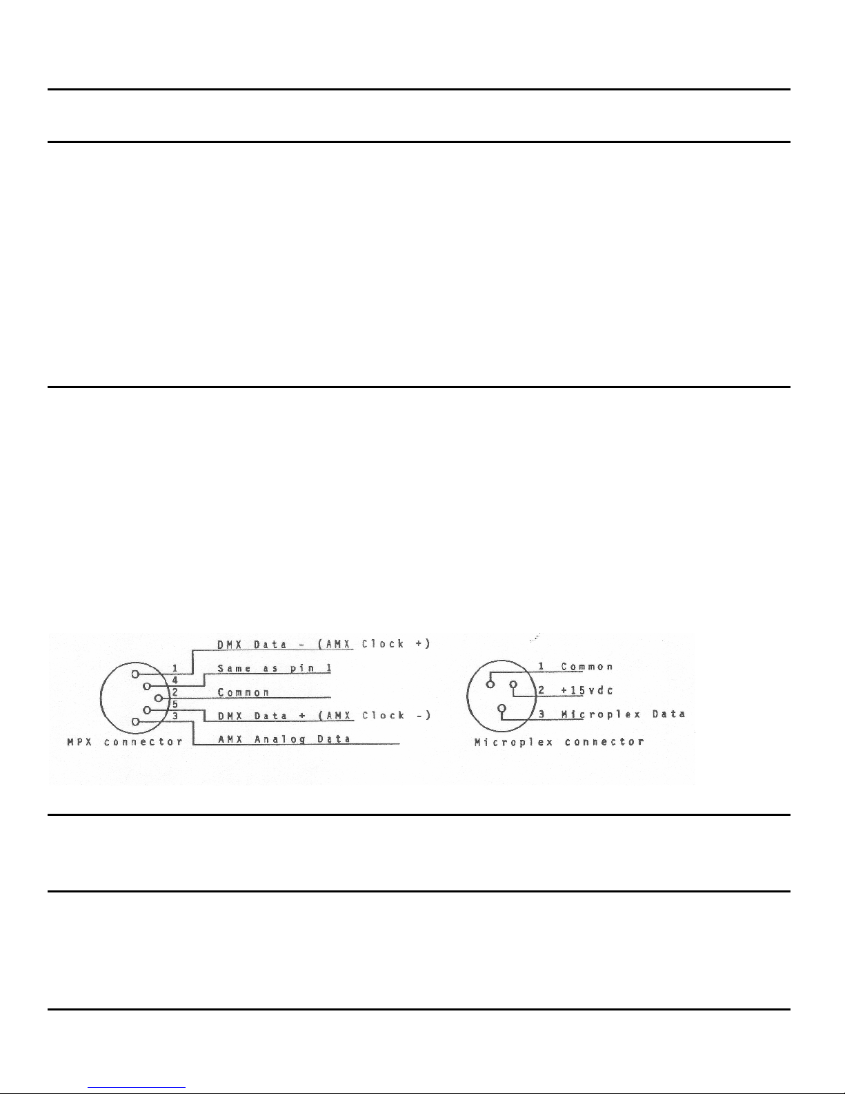
If the NCM 72 SERIES is being connected to a DMX-512 or AMX-192 multiplex dimming system then a standard 5 pin "DIN"
connector (ie. Switchcraft #05JL5M) must be wired to the multiplex cable to the dimming system as illustrated. Insert the multiplex
cable into the MPX jack on the back of the console.
If an external power supply is used it should be located near the consol e and connected with a short "mic" cord to the remaining
MICRO-PLEX jack on the back of the console.
The first time the NCM 72 SERIES is used, the configuration parameters may need to
be set, otherwise the unit may appear to be operating improperly. Please see reference part of manual on CONFIGURE MODE.
Please read through the trouble-shooting checklist at the end of this manual, prior to using this console, to help avoid common
problems.
NSI CORPORATION 4
Configuration
Trouble?
Page 7

NCM 7216 / 7232 Quick Operation Guide
Software Revision 1.44 and above Short Cuts
3 Quick Operation Guide
Short Cuts
It Is Advisable To Read Your Owners Manual Completely In Order To Fully Understand The capabilities of your new NSI 72 series
console. However, if you need to operate the unit immediately, it can be quickly configured as a two scene controller by following
these steps.
1. Connect the microphone cable from the dimmer packs.
2. LCD display will light and display name banner.
3. After a few seconds, either 2SC or STD will appear in upper right hand corner of display.
¾ If 2SC is shown; two scene operation is locked on, so pr oceed to step 6.
¾ Otherwise follow the next steps.
4. Press the CONF MODE button; LCD will prompt for configuration.
5. Press MEMORY SCENE #6 to set the console mode. The LCD display will indicate "STANDARD" mode.
¾ Press MEMORY SCENE button #1 and the "TWO SCENE" mode should n ow appear in LCD.
¾ Note that pressing MEMORY SCENE button #1 again will toggle the console back and forth between "STANDARD"
and "TWO SCENE" mode.
¾ Leave the console in the "T WO SCENE" mode an d hit the B/O button.
6. The X-Y crossfaders are now assigned to SCN A and SCN B and function as follows:
¾ Whenever both the X and Y CROSSFADER controls are in the fully up position; SCN A slide controls will
directly operate lights.
¾ Whenever both CROSSFADER controls are in the down position; SCN B will operate lights.
¾ BUMP buttons will flash respective lighting channels.
¾ The MASTER LEVEL control must be up for lights on stage to operate.
¾ The B/O button will cause all stage lights to fade out at the set fade rate, and one or both of the X-Y
CROSSFADER LEDS will flash indicating a blackout condition. You can move the MASTER LEVEL to full down
to reset the X-Y CROSSFADER controls.
7. For more details see section on "Two Scene Operation .
NSI CORPORATION 5
Page 8

NCM 7216 / 7232 Basic Operation Guide
Software Revision 1.44 and above Two Scene Mode
4 Basic Operation Guide
Two Scene Mode
The 72 SERIES console may be placed in a "two-scene" operating mode which simulates the operation of simple manual lighting
controllers.
This operating mode is recommended for learning basic operation of the 72 SERIES. It is also us eful for times when an operator is
unfamiliar with the advanced features of the console and would feel more comfortable with t wo-scene co ntrol constantly available.
To place the console in the two-scene operating mode follow these steps.
1. Press CONF MODE button. The LCD will prompt for a configuration selection.
2. Press MEMORY SCENE #6 to access console mode configuration.
3. Press MEMORY SCENE #1 to toggle console operating mode until LCD display reads T WO-SCENE.
4. Press B/O button to leave configure mode.
The console will remain in the two-scene mode until either re-configured or power is removed.
NOTE: The console can be set to power-up in this or other operating mode by following directions listed under Installation
Parameters located in the reference section of the manual.
Bump Buttons
The BUMP BUTTONS on the NCM 72 series console are used to force any lighting channels to full intensity regardless of other
console settings. These buttons are useful for flashing lights, turning lights on momentarily, or "panic" buttons for when something
unexpected happened that you were not set up for and you need to turn on some lights fast.
To demonstrate the function of the BUMP BUTTONS simply press one or any combination of BUMP BUTTONS and notice that the
respective lights immediately come to full intensity.
Channel Level Leds
A row of clear LEDS along the top of the NCM 72 series console is for displaying the relative lighting levels sent to stag e. Note that the
MASTER LEVEL control affects the stage lighting levels without affecting the LEDS.
NSI CORPORATION 6
Page 9

NCM 7216 / 7232 Basic Operation Guide
Software Revision 1.44 and above Two Scene Operation
Two Scene Operation
The following instructions will guide you through the simple proc edures for basic creation and and execution of lighting cues.
NOTE: This section assumes that the console is in the "TWO-SCENE" operating mode as outlined above.
The term "Two-Scene" refers to having two complete sets of identical controls (or "presets") for all lighting channels. These controls
are used to create combinations or lighting levels for a particular "look" on stage (or "scene ").
All lighting control output from the console is controlled by the MASTER LEVEL control. Each of the two sets of presets has a slide
control which controls the overall intensity of each set of lighting levels cal led a crossfader. The crossfader control for SCENE A is at
maximum when in the fully up position, while the crossfader control for SCENE B is at maximum when in the fully down positi on. This
allows the two scenes to blend from one to another by moving both controls simultaneously up or down together, thereby "crossfading"
from one scene to another.
While SCENE A is fully on (or "active") SCENE B can be reset to new lighting levels for the new cue. Then by moving both the
crossfader controls, SCENE B is made active and SCENE A can be reset if desired. This type of operation allows easy composition
and execution of lighting cues. To demonstrate TWO-SCENE operation:
1. First move the MASTER LEVEL slide control and both the X and CROSSFADER controls to the fully down position.
2. Now, preset a lighting scene by moving several of the SCENE A slide controls to approximate desired lighting levels.
Nothing will happen on stage at this point.
3. To bring up this scene, move both the X and Y CROSSFADER controls to fully up and move the MASTER LEVEL
control to fully up. Stage lights should now come up to levels preset on SCENE A slide controls.
4. Preset another lighting scene using SCENE B slide controls.
5. Slowly move both X and Y CROSSFADER controls to the fully down position. Stage lights should gradually change to
levels preset on SCENE B slide controls.
6. Preset another lighting scene using SCENE A slide controls.
7. Slowly move both X and Y CROSSFADER controls to the fully up position. Stage lights should gradually change to levels
preset on SCENE A slide controls.
8. Repeat steps 4 - 7 several times.
NSI CORPORATION 7
Page 10

NCM 7216 / 7232 Basic Operation Guide
Software Revision 1.44 and above Blackout Button
Blackout Button
The BLACK-OUT button on the NCM 72 Series consoles allows for a c o nveni ent meth od to caus e al l functions to gra duall y fad e out or
instantly go to black.
The BLACK-OUT button is "touch sensitive" in that a light tap will cause all lights to fade out at a setting determined by the fade rate
control. While a press and hold motion will cause an instant blackout.
In order to blackout SCENE A and SCENE B presets, the X CROSSFADER must be moved fully down while the Y CROSSFADER
must be moved fully up. Since the console cannot physically move the crossfader controls, in order to blackout the SCENE A and
SCENE B presets, it must take over control of either or both of the crossfaders electronically. When this happens the LED below the
crossfader control will flash quickly indicating the crossfader is temporarily inoperative. To regain control when needed you can do one
of three things:
¾ Move the MASTER LEVEL control to the fully down position.
¾ Move the affected crossfader to the minimum position.
¾ Tap the LOAD BUTTON below the crossfader causi ng the scene affected to fade back on.
The following steps demonstrate the use of the BLACKOUT BUTTON with the crossfader controls.
1. Move the MASTER LEVEL control to the fully up position.
2. Set up a scene on the SCENE A presets and crossfade to it by moving both crossfaders to the fully up position. The
scene should now be on stage.
3. Move the fade rate slide control to about mid position. The LCD display win show the fade time in seconds from "F00" to
"F99".
4. Tap the BLACKOUT button and the B/O LED should light and the stage lights along with the channel level LEDS should
gradually fade out. The LOAD LED beneath the X CROSSFADER should start flashing, indicating that the console h as
taken over control of the crossfader.
5. Move the MASTER LEVEL control to the fully down position and notice that the LED stops flashing and the channel leve l
LEDS will restore to previous levels. This is the usual procedure to follow after a blackout. Now you would normally set
up the console for the next event and then raise the MASTER level control when ready.
6. Repeat steps 1 - 4 above and try moving the X crossfader fully down and then slowly raise it again.
7. Repeat steps 1 - 4 above and try tapping the LOAD button for the X crossfader to restore the scene.
NSI CORPORATION 8
Page 11

NCM 7216 / 7232 Basic Operation Guide
Software Revision 1.44 and above Memory Scenes
Memory Scenes
The 72 series consoles have the ability to store scenes in digital memory for later recall. Scene memory may be either programmed
from the setting of the SCENE A channel level slide controls or may be copied from an actual look on stage.
The memory of the console is divided up into 8 pages. A page is a collection of 16 or 32 scen es (depending on the capacity of the
console). Once a page is selected, the scenes of 1/2 of the page are available for storage or recall at the touch of one of the MEMORY
SCENE buttons. Whether the first half or second half of the page is available is dependent upon the setting of the SCENE SELECT
button.
For Example;
¾ The NCM 7216 has 8 pages of 16 scenes each.
¾ Either scenes 1 - 8 or scenes 9 - 16 can be made available.
¾ The NCM 7232 has 8 pages of 32 scenes each.
¾ Either scenes 1 - 16 or scenes 17 - 32 can be made available.
Tapping the PROGRAM SCENE A button followed by tapping a MEMORY SCENE button will store the settings of the SCENE A
channel level controls into memory at a location determined by the MEMORY SCENE button pressed and the current page and
SCENE SELECT settings. This is called "blind" programming because the lighting levels are not presented on stage.
Tapping the PROGRAM STAGE button follow by tapping an appropriate MEMORY SCENE button will store the stage levels
regardless of the setting of the MASTER LEVEL control) into a specific memory location: This is called "live" programming bec ause
lighting levels programmed are the actual levels on stage.
To recall a memory scene; Tap the desired MEMORY SCENE button by itself (make s ure neither of the PROGRAM leds are fit). The
green led above the button will light and t he scene stored at the selected memory location will fade on at the fade rate set by the
FADE RATE control. If the same MEMORY SCENE button is tapped again the green led will extinguish and the scene will fade out. If
the MEMORY SCENE button is held down when recalling a scene, the scene will fade up quickl y, after a .2 second delay.
When the scene fades up it will add to any other scenes activated on the conso le (including manual scenes). If the SCENE SPLIT is
off, any previous memory scene will be deactivated and will fade out at the set rate. If SCENE SPLIT is on then only the memory
scenes on the same side of the split will be canceled.
The following steps demonstrate blind programming and recalling of memory scenes:
1. First press and hold down B/O to blackout any manual and memory scenes currently active. Do not reset the manual X-Y
crossfaders.
2. Now using the SCENE A slide controls, create a lighting scene by moving the controls to desir ed levels.
3. Make sure that the SCENE SELECT button is in either the 1-8 or 1-16 position. Tap the button to set the correct mode.
4. Tap the SCENE A PROGRAM button and the LCD will prompt for scene to program.
5. Tap a desired MEMORY SCENE button and the channel level settings of SCENE A will be stored in memory.
6. Now by setting the FADE RATE control to a 5 - 10 second fade time and then tapping the same MEMORY SCENE
button, the programmed memory scene should fade up.
Note: lower right hand corner of LCD indicates progress of fade up or fade down.
NSI COPRORATION 9
Page 12

NCM 7216 / 7232 Basic Operation Guide
Software Revision 1.44 and above Memory Scenes
7. Repeat the above steps several times using different settings of the SCENE A controls and different MEMORY SCENE
buttons.
8. After several Memory Scenes have been programmed, repeat just step #6 above several times to show that scenes
remain in memory.
The following steps demonstrate live programming and recalling of memory scenes:
1. First press and hold down B/O to blackout any manual and memory scenes currently active.
2. Use the TWO-SCENE operation, as discuss previously, and create a lighting scene on stage.
3. Make sure that the SCENE SELECT button is in either the 1-8 or 1-16 position. Tap the button to set the correct mode.
4. Tap the. STAGE PROGRAM button and the LCD will prompt for scene to program.
5. Tap a desired MEMORY SCENE button and the channel level settings of the stage win be stored in memor y.
6. Black Out the console and set the FADE RATE control to a 5 - 10 second fade time and then tag the same MEMORY
SCENE button. The programmed memory scene should now fade up.
7. Repeat the above steps several times using different Scenes on stage and different MEMORY SCENE buttons. You can
even use previously programmed memory scenes to create your scen e o n stage.
The following steps demonstrates programming and recalling of memory scenes from the other half of the memory page:
1. Program a memory scene using any method discuss previously.
2. Press the SCENE SELECT button the select memory scenes 9-16 or 17-32. Now the MEMORY SCENE buttons will
correspond to memory scenes 9 - 16 or 17 - 32.
3. Now program a new memory scene using a different memory scene button.
4. Change the SCENE SELECT button to either the 1-8 or 1-16 position.
5. Set the FADE RATE control to a 5 - 10 second fade time and then tap the MEMORY SCENE button used in step #1
notice that the first programmed memory scene should fade up.
6. Change the SCENE SELECT button to either the 9-16 or 17-32 position.
7. Tap the MEMORY SCENE button from step #3 notice that the next programmed memory scene should fade up.
8. Repeat the above steps, this time using the same MEMORY SCENE button for both steps #1 and #3. Notice that the
same memory scene buttons are actually different memory locations when the SCENE SELECT is changed.
NSI CORPORATION 10
Page 13

NCM 7216 / 7232 Basic Operation Guide
Software Revision 1.44 and above Chases
The following steps demonstrates programming and recalling of memory scenes from different memory pages:
1. Program a memory scene using any method discuss previously.
2. Hold down the PAGE button and tap the SCENE SELECT button until the LCD indicates AUTO page 2.
3. Now program a new memory scene using a different memory scene button.
4. HOLD down the PAGE button and tap the SCENE SELECT button until the LCD indicated AUTO page 1.
5. Now tap the MEMORY SCENE button used in step #1, notice that the first programmed memory scene should fade up.
6. Hold down the PAGE button and tap the SCENE SELECT button until the LCD indicates AUTO page 2.
7. Tap the MEMORY SCENE button from step #3 notice that the next programmed memory scene should fade up.
8. Repeat the above steps, this time using the same MEMORY SCENE button for both steps #1 and #3. Notice that the
same memory scene buttons are actually different memory locations when the PAGE is changed.
Chases
The NSI 72 series consoles have a tremendous capability for designing, programming and executing ch ases. A chase is a sequence
of lighting changes which continuously repeats over and over. A total of 16 separate chases can be programmed into the console's
non-volatile memory. Eight of the chases are programmable in steps co nsisting of a combination of any control channels at either
full-on or fun-off. The other eight chasesare scene chases and are programma le in steps consisting of any scene stored in scene
memory. Scenes programmed into a scene chase can be from any page in memory. Ifa memory scene is reprogrammed afterwards,
any scene chase utilizing that scene is also affected. All chases can have as few as two, and as many as 32 steps.
Normal chases can be activated using the CHASE SELECT and MEMORY SCENE buttons #1 - #8. Scene chases can be activated
using the CHASE SELECT, SCENE SELECT and MEMORY SCENE buttons #1 - #8. Once activated, the chase will fade on at the
rate determined by the fade rate control, while any previous chase select ed will fade out at the save rate. If the MEMORY SCENE
button used to select the chase is held down, the chase will quick ly fade on. The rate at which the chase sequences is set by the
CHASE RATE control or by tapping the chase sync button at the rate desired. A chase can be manually sequenced or momentarily
stopped by using the CHASE button or by supplying an audio signal to the console and activating the AUDIO button.
Chases are programmed by first selecting and activating th e desired chase. T hen press the SCENE A PROGRAM button follo wed by
pressing the CHASE button. If a normal chase is being programmed, just set the desired channel level controls of SCENE A to full on,
with the other channel level controls to full off. If a scene chase is being programmed, select the desired memory scene using the
MEMORY SCENE buttons. Now by pressing the CHASE button, the step is stored in memory and and the sequence number is
advanced to the next step.
On the NCM 7232 console only, chases may also be stored in the AUXILIARY SUB MASTERS This gives full level control to selected
chases and allows multiple chases to be activated simultaneously. See the following section on AUXILIARY SUBMASTERS.
NSI CORPORATION 11
Page 14

NCM 7216 / 7232 Basic Operation Guide
Software Revision 1.44 and above Chases
The following procedure demonstrates programming and activating a normal chase as well as a operating the other chase functions.
1. Press the B/O button to clear any active console functions.
2. Press the CHASE SELECT button and the LCD will prompt for the chase number.
3. Press the MEMORY SCENE #1 button to select normal chase number 1. The LCD will indicate the selected normal
chase (CN1).
4. Press the PROGRAM SCENE A button followed by pressing the CHASE button. The LCD will now show the chase
being programmed and the current step number.
5. Select the lighting channels to be on for this step of the chase by moving the associated SCENE A channel level slide
controls to their full on position. Move the remaining SCENE A channel level slide controls all the way down. The channel
level LEDS will indicate the selected channels.
6. Now press the CHASE button to store the step in non-volatile memory. The LCD display will now indicate the next step
to be programmed.
7. Repeat step 5 and 6 several times to store some more steps in memory. When done ress the B/O button twice to
terminate the chase program mode. Chase #1 has now been programmed.
8. To recall and activate chase #1; set the FADE RATE control for a setting of 4-5 seconds and set the CHASE RATE
control for 100-200 beats per minute.
9. Press the CHASE SELECT button and the LCD will prompt for the chase number.
10. Tap the SCENE MEMORY #1 button the activate the chase. The chase previously programmed should now fade in and
continue sequencing.
11. Tap the CHASE SYNC button 3 times rapidly. Notice how the chase rate changes to match your taps. Repeat this step a
few times.
12. Press and hold the CHASE button down for a few seconds and notice how the chase sequence stops while the button is
being held down.
13. Move the CHASE RATE control to it's minimum (full down) position the chase sequencing should come to complete halt.
14. Tap the CHASE button several times and notice that the chase will single step on each tap. Move the CHASE RATE
control back to it's original position.
15. To deactivate the chase press the CHASE SELECT button followed by tapping the B/O button. The chase will now fade
out at the set fade rate.
NSI CORPORATION 12
Page 15

NCM 7216 / 7232 Basic Operation Guide
Software Revision 1.44 and above Chases
The following procedure demonstrates programming and activating a scene chase. This procedure requires that several memory
scenes be programmed. If you have not yet done this, go back to the section on memory scenes and program some scenes.
1. Press the B/O button to clear any active console functions.
2. Press the CHASE SELECT button followed by the SCENE SELECT button and the LCD will prompt for the scene chase
number.
3. Press the MEMORY SCENE #1 button to select scene chase number 1. LCD will indicate scene chase number (CS1).
4. Press the PROGRAM SCENE A button followed by pressing the CHASE button. The LCD will now show the scene
chase being programmed and the current step number.
5. Select the memory scene to use for this step of the chase by pressing the desired MEMORY SCENE button. The
channel level LEDS will indicate the selected memory's channel levels.
6. Now press the CHASE button to store the step in non-volatile memory. The LCD display will now indicate the next step
to be programmed.
7. Repeat step 5 and 6 several times to store some more steps in memory. When done press the B/O button twice to
terminate the chase program mode. Scene chase #1 has now been programmed.
8. To recall and activate scene chase #1; set the FADE RATE control for a setting of 4-5 seconds and set the CHASE
RATE control for 100-200 beats per minute.
9. Press the CHASE SELECT button followed by the SCENE SELECT button and the LCD will prompt for the scene chase
number.
10. Tap the SCENE MEMORY #1 button the activate the chase. The chase previously programmed should now fade in and
continue sequencing.
11. To cancel the chase; press the CHASE SELECT button again follo wed by tapping the B/O button.
Try repeating these procedures with different chase numbers by using different MEMORY SCENE buttons to select the chases. T r y
programming the maximum of thirty-two steps for a chase, and fading from one chase to another.
NSI CORPORATION 13
Page 16

NCM 7216 / 7232 Basic Operation Guide
Software Revision 1.44 and above Auxiliary Submasters
Auxiliary Submasters
(This feature is present on NCM 7232 only). The auxiliary submasters can be progr ammed with scene levels and / or chases. The
slide controls vary the overall intensity of the channel levels programmed into the submasters. These levels will add to the other
submasters levels and any other levels from other console functions which are currently active.
The auxiliary submaster BUMP buttons will cause the programmed channel levels to come to full relative intensity, and can be
configured for momentary or push-on push-off operation using the co nfiguration mode. The auxiliary submaster BUMP buttons are
also used for programming the submasters by pressing either the SCENE A PROGRAM or the STAGE PROGRAM button followed by
the desired BUMP button.
After pressing B/O, if an auxiliary submaster level control is above minimum, the submaster may automatically fade out and the LED
above the associated BUMP button will flash. To regain control of the auxiliar y submaster; either move the submaster control to fully
down or move the MASTER LEVEL slide control to minimum. The LED will go out when control is regained. To demonstrate
programming the auxiliary submasters with a simple scene; follow this procedure.
1. Press the B/O button to clear any active functions.
2. Setup desired channel levels on the SCENE A slide controls.
3. Press the SCENE A PROGRAM button followed by pressing the BUMP button of the desired auxiliary submaster.
4. Move the selected auxiliary submaster slide control up and down to demonstrate the programming.
To demonstrate programming the auxiliary submasters with a chase; follow this procedure.
1. Press the B/O button to clear any active functions.
2. Select a previously programmed chase using the CHASE SELECT button. Set the chase rate control for 100-200 BPM.
3. Press the STAGE PROGRAM button followed by pressing the BUMP button of the desired auxiliary submaster.
4. Move the selected auxiliary submaster slide control up and -down to demonstrate the programming.
NSI CORPORATION 14
Page 17

NCM 7216 / 7232 Basic Operation Guide
Software Revision 1.44 and above Scene Master Operating Mode
Scene Master Operating Mode
Software release 1.43 and after have added a new operational mode to the current T wo Scene and Standar d modes, called the Sce ne
Master mode. This new mode causes the X-crossfader to be permanently loaded with Scene A and the Y-crossfader to be
permanently loaded with Submaster Group B.
As in the Two Scene mode, the Scene A Select, Scene B Select, Submaster A, Load X, and Loa d Y buttons do n ot function. However,
the Submaster B button does function. Its use is limited, however, to the Scene B bump buttons. When the mode invoked, the
Submaster B LED is lit and the bump buttons act as scene bumps. Pressing the Submaster B button will toggle the LED off to allow
single channel bumping.
It should be noted that the Y-crossfader continues to be loaded with Submaster Group B and that the Submaster Group B sliders are
active even though the Submaster B LED is not lit. In this way, the bump buttons can be available for channel bumping at the same
time that the Submaster Group B sliders are active with scenes.
The LCD display will read "SMR" in the upper righthand corner whenever the console is in the Scene Master mode.
To activate the Scene Master mode, do the follow ing steps:
1. Tap the "CONF MODE" button.
2. Tap Memory Scene 6. The LCD display should read "CONSOLE MODE" on the first line and the current mode on the
second tine.
3. Tap Memory Scene 1 until the second line of the LCD display reads "SCENE MASTER".
4. Tap the Blackout button to exit.
At this point the console will operate in the Scene Master mode until it is powered down. When powered up, the old mode will be
active.
To program a scene into Submaster Group B:
1. Set up lighting scene on Scene A faders, or on stage using any combination of levels.
2. Press either the SCENE A PROGRAM or STAGE PROGRAM button.
3. Press the BUMP button under the respective Submaster Group B fader.
To cause the console to power up in Scene Master mode, do th e following:
1. The console should first be in the Scene Master mode-. If not, follow the above steps first.
2. Tap the "CONF MODE" button.
3. Tap Memory Scene 8. The LCD display will prompt for a key-code.
4. Enter the code 2-3-2-7 using the Memory Scene buttons. The LCD display will read "MAX DIM:".
5. Using the Scene Select button cycle through the installation modes until the LCD display reads "POWER UP INIT".
6. Tap Memory Scene 1.
7. After about 2 seconds, tap the Blackout button. The console wilI now power up in the Scene Master mode.
NSI CORPORATION 15
Page 18

NCM 7216 / 7232 72 Series Reference Guide
Software Revision 1.44 and above Slide Controls
5 72 Series Reference Guide
Slide Controls
Grand Master
This slider continuously controls the output level of the console to the dimmers. T he led Control dis play of stage levels is not affected.
If this control is set to minimum when the BLACKOUT button is pressed then autofading of the X-Y CROSSFADERS and
SUBMASTERS is prevented.
X/Y Crossfaders
The slide controls can be loaded with any manual scene or memory scene (except in two scene mode) and used to facilitate manual
fades from one scene to another. Any scene loaded into the X crossfa der will be at maximum when the control is a its top position.
Any scene loaded into the Y crossfader will be at maximum when the control is at the bottom posit ion. If a crossfader was not set at
minimum when a scene is to be loaded, then the led above the respective load button will blink and the crossfader will have no effect
on the scene. At this point the user has two options: The load button can be pressed a second time, causing the scene to fade to the
crossfader setting at a rate determined by the fade rate control, or the crossfader can be moved to a level matching the loaded scene.
The led will go out when the scene level matches the crossfader s etting, and the crossfader will then have full control over the overall
intensity of that scene.
Auxiliary Submaster Level Controls
These four sliders are present only on the NCM 7232. Four independent scenes may be programmed into these submasters using
either the STAGE PROGRAM or SCENE A PROGRAM buttons. Lighting levels stored in each submaster will combine with any other
current lighting levels with the highest level having precedence, when the submaster control is set above minim um. Chases may also
be programmed in the auxiliary submasters by programming the submaster using the stage program pushbutton while a chase is
active and on stage. Intensity levels of the chase will be continuously cont rolled by the appropriate submaster control. Four different
submaster chases plus the normal chase may be active at the same time.
Scene Channel / Submaster Level Controls
CHANNEL MODE: When the Submaster mode is inactive for manual scene A or B (s ubmaster button led is off) the 16 or 32 man ual
scene slide controls correspond to individual lighting c hannel levels. If a manual scene is activated, then the stage li ghting levels will
crossfade to the levels set by the manual scene slide controls. Some real time control of lighting levels is available using these slide
controls-at this time, but full control will not be realized until the crossfade is complete (X or Y level is 100%).
Slide controls of the manual scene A can also be used for blind programming of any memory scene or submaster. This is
accomplished by pressing the SCENE A PROGRAM BUTTON and then pressing the button of the desired memory scene or
submaster. For blind programming this must be done when the manual scene A is not active.
SUBMASTER MODE: (Not available in 2 SCN mode). The slide controls for manual sc ene A or B can also function a s submasters for
scenes stored in memory. This can be done by first making sure that the manual scene to be used as a submaster group is inactive
and completely faded out. Then the desired memory page to use as a submaster group can be selected by holding down the PAGE
button while tapping the SUBMASTER MODE button of the desired memory scene.
Now the submaster group mode can be activated by pres sing the SUBMASTER mode button of the desired memory scene, and th e
led above the button will light. The individual sliders will now control the levels of each of the memor y scenes stored in the
memory. The manual scene can then be crossfaded in the same manner as when it was in the channel mode.
NSI CORPORATION 16
page of
Page 19

NCM 7216 / 7232 72 Series Reference Guide
Software Revision 1.44 and above Pushbuttons
Chase Rate: This slider controls the rate at which the a selected chase will sequence unless C14ASE S YNC is used to establish the
chase rate. When the chase rate control is at the minimum position, the chase will stop and can b e manually sequenced with the
CHASE button.
Audio Level: This slider controls the sensitivity of the audio input signal. This control should be adjusted at the minimum level
required to obtain the desired effect.
Fade Rate: This control continuously varies the rate at which any scene autofades. T he fade rate is displayed on the LCD d isplay in
seconds. If a particular scene's button is pressed and held down, the fade rate will be overridden and the scene will fade instantly. This
control also serves as a "data entry' control in some configuration modes.
Pushbuttons
Blackout: The BLACKOUT button is designed to allow a complete and automatic fadeout of all functions of the consol e wit h a sin gle
press. Pressing the BLACKOUT button by itself will cause several events to take place:
¾ The Blackout Led will light an d any autofade memory scene will be released and will fade out.
¾ Any piled-on scene will be released an d will fade out.
¾ If either of the X-Y crossfaders, and the master level control is set above minimum, the LOAD led will flash and the crossfader
will start an automatic fadeout.
¾ If any of the Auxiliary Submaster controls, and then master level control is set above minimum, the associated submaster led
will- flash and the Auxiliary submaster will start an automatic fadeout.
¾ All fades will take place at the rate determined by the fade rate control unless the BLACKOUT button is held down, which will
cause a quick fadeout.
¾ The BLACKOUT button can also be used in conjunction with the PILE, CHASE, and LOAD buttons to cancel or blackout
individual functions.
X and Y Load: (Not available in 2 SCN mode.) The X - Y LOAD buttons are used to load scenes into either crossfade slide control.
This will give manual control to the overall level of the scene loade d. Once a LOAD button is tapped the LED above it will light steadi ly
indicating that it is ready to accept a memory scene or manual scene. To cancel a load operation, simply tap the LOAD button again.
Once the -,desired scene has been selected for loading, the LED will either flash quickly indicating a control level mismatch or the LED
will extinguish,, indicating a scene has been loaded.
Loading Scenes Into Manual Crossfaders: Memory scenes and the A and B manual scenes can be loaded into either manual
crossfader. This can be accomplished by pressing the X or Y LOAD button, then pressing the select button of either a memory scene,
or one of the A or B manual scenes. If the position of the manual crossfader control to be load ed is not set at minimum level (X : full
downward, Y : full upward) then the led above the respective load button will flash quickly and the cr ossfader control will have no effect
on scene levels.
The operator then has two choices. The operator can choose to force the new scene levels to fade to the current settings of the
manual crossfaders by pressing the LOAD button a second time. Any previously loaded scene levels will fade out at the set fade rate.
Otherwise the manual crossfader control can be moved to the minimum se tting at which point the led will go o ut and manual contr ol of
the scene will be obtained.
NSI CORPORATION 17
Page 20

NCM 7216 / 7232 72 Series Reference Guide
Software Revision 1.44 and above Pushbuttons
Clearing Manual Crossfaders: The manual crossfaders may be cleared by first pressing the LOAD button of the appropriate
crossfader to clear, and then by pressing the B/O button. If the crossfader was not set at minimum( X : fully down, y : fully up ), and the
master level control is set above minimum, the LED above the LOAD button will start flashing quickly. You may then tap the same
LOAD button again to start a fade out of the previous scene loaded in the crossfader at the current fade rate or move the
crossfader control to minimum.
Scene A and Scene B Select: (Not available in 2SC mode)
USE WITH AUTOFADE: To use SCENE A or SCENE B with the autofader, set the desired fade rate with the fade rate control. Then
adjust the SCENE A or SCENE B slide controls to the desired levels. Tapping the SELECT button of the desired SCENE will then
initiate the fade of stage levels to the slide control settings. A press and hold of the SELECT button will cause the fade to happen
instantly.
USE WITH MANUAL CROSSFADERS: Either SCENE A or SCENE B can be loaded into a manual crossfader by first pressing the X
or Y LOAD button under the crossfaders and then pressing the SELECT button for the desired scene. It should b e noted that the
crossfader should be set to minimum before loading, else the LED above the LOAD button will flash quickly and the crossfader will
have no effect on the scene. The previous discussion on crossfaders describe the options available at this point.
USE WITH PILE-ON: The manual scene can be used independently in "real-time" by first tapping th e PILE-ON SCENE button and
then the SELECT button of the desired manual scene. This will cause the manual scene to fade up at the current autofade rate. Once
selected, the LED above the SELECT button will flash and the manu al scene will stay active regardless of any proceeding auto or
manual crossfades. To cancel the pile-on, simple tap the SELECT button again or use the BLACKOUT button. This will cause the
scene to fade out at the current autofade rate.
Scene A and Scene B Submaster Mode: The SUBMAST ER MODE A or B button will cause the slide controls to change their
function from controlling individual channel levels to controlling entire memory scene levels. Any of the above manual scene
functions will operate normally except that the manual scene will consist of a group of submaster levels instead of in dividual channel
levels.
To change a manual scene to a subgroup, first make sure the LED above the SELECT button is off. Then move all the manual scene
slide controls to minimum. Now select the page of memory to be assigned to the subgroup. At this point tap the SUBGROUP
making sure the LED above it is lit. The slide controls will now correspond to memory scenes from the selected page and can be
crossfaded and piled-on in the same manner as the manual scene.
To cancel the subgroup mode and return the slide controls to individual channel control, repeat the above operations, with the
exception that the subgroup LED should now be extinguished.
Bump Buttons: Depending on the setting of the SUBMASTER MODE button of SCENE B, the BUMP buttons can be used for
bumping (flashing) either individual channel levels or entire memory scenes of the page assigned to SCENE B. The SELECT button
does not need to be active for scene B.
When scene B is in the subgroup mode the BUMP buttons can be used to reprogram the memory scenes in the page currently
assigned to scene B. To reprogram a memory scene, either tap STAGE PROGRAM to copy stage levels or SCENE A PROGRAM to
copy the levels of scene A into memory. Then tap the BUMP button corresponding to the desired memory scene.
NSI CORPORATION 18
Page 21

NCM 7216 / 7232 72 Series Reference Guide
Software Revision 1.44 and above Pushbuttons
Memory Scene Buttons: The memory scene buttons correspond to either scenes 1 - 16 (NCM 7216: 1 - 8) or scenes 17 - 32 (NC M
7216: 9 - 16) of the current memory page displayed in the LCD, depending upon the mode of the SCENE SELECT button.
These buttons can be used for autofading memory scenes by tapping the desired MEMORY SCENE button. This will cause the
memory scene to fade in at the current autofade rate. A press and hold will cause an instant fade. Any current memory scene or
manual scene not piled-on will fade out at the current autofade rate.
A split may be programmed into the MEMORY SCENE buttons causing the right half of the split to op erate independently of the left
half. This may be accomplished by following the instructions under CONFIGURATION MODE. If a Memory Scene is active on the
right side of the split, it will not be affected by pressing a MEMORY SCENE button on the left side and visa versa.
Memory scenes may be piled-on by first tapping the PILE-ON button and then tapping the desired memory scene. The memory scene
will fade in at the current autofade rate and the LED above the PILE-ON button will light until the pile-on has been released.
Other scenes can be added in the same manner. To release all memory scene pile-ons, tap the PILE - ON button followed by tapping
the B/O button which will cause the pile-on to fade out at the current autofade rate.
Memory scenes can also be loaded into the manual cr ossfader or reprogrammed using these buttons as outlined in the appropri ate
section.
Memory Scene Select: This button determines which half of a memory page the MEMORY SCENE buttons will access. The two
LEDS above the SCENE SELECT button will toggle with each tap of the button, indicati ng the half of the memory page active to the
MEMORY SCENE buttons.
Auxiliary Submaster Bump / Prog Buttons: These buttons are only available on the NCM 7232. Submaster scenes may be
programmed by tapping either the STAGE PROGRAM button or SCENE A PROGRAM button, and then the desired submaster
BUMP/SELECT button. The BUMP/SELECT buttons used by themselves operate as bumps (flashes) for the overall corresponding
submaster levels programmed.
Chase: The CHASE button can be used to manually sequence all chases with individual taps of the button if the chase rate c ontrol
slider is at its minimum setting. Pressing the CHASE button will also stop sequencing of all chases until the CHASE button is released.
The last chase selected by the CHASE SELECT button can - be reactivated by pressing the CHASE SELECT button followed by
pressing the CHASE button.
Audio: The AUDIO button toggles the audio mode. The LED lit indic ates that the au dio mode is o n. T he audio mode affects all chas es
when active. When the chase rate control is in the minimum position, the chases will sequence with the audio input low frequency. The
AUDIO button can also be programmed to cause the audio sign al to effect the intensit y of certain lighting ch annels. This can be done
selecting the channels to be affected using the SCENE A slide controls. Press the SCENE A PROGRAM button
followed by the AUDIO button.
Solo: The SOLO mode is activated by pressing the SOLO button. The next memory scene or m anual button pressed will cause all
lights to fade out at the set fade rate and the selected scene will fade on. Another scene may replace the previous solo' d scene by
repeating the above procedure. SOLO is canceled by selecting a scene without first tapping the solo button or by B/O.
Chase Sync: If a chase is to be synchronized with an event on stage, simply tap the CHASE SYNC button in step with the event
either just before or after the chase is activated. Two taps are required for the CHASE SYNC to operat e, tapping it on ce may just stop
or slow the chase. Any change in the chase rate control fader will take over chase sequencing rate. The Chase Rate is indicated on
the LCD display in beats per minute.
NSI CORPORATION 19
Page 22

NCM 7216 / 7232 72 Series Reference Guide
Software Revision 1.44 and above Pushbuttons
Chase Select: The 72 Series consoles have the capacity for 16 programmable chases comprised of the following.
¾ 8 Standard Chases which can be programmed for 32 steps each. Each step consists of any combination of all of the control
channels, either full on or full off.
¾ 8 Scene Chases which can be programmed for a sequence of 32 different lighting scenes already stored in memory.
The CHASE SELECT button is used to initiate one of the 8 standard chases by first tapping the C14ASE SELECT button. Then
MEMORY SCENE buttons I - 8 are then used to select the desired chase by simpl y tapping the corresponding button. The chosen
chase number will be displayed on the LCD and the chase will fade in at the set fade rate while a previous chase will fade out.
To select one of the 8 Scene Chases, first tap the C14ASE SELECT button followed by tapping the S CENE SELECT button. Now by
pressing one of the MEMORY BUTTONS I - 8 a preprogrammed scene sequence will ac tivated and the sequence number will be
displayed on the LCD display.
Memory Page: The MEMORY PAGE button selects memory pages for scene storage and recall. Separate pages may be selected for
the autofaders (MEMORY SCENE buttons), and submaster modes for manual SCENE A and B. To display or select which of the 8
pages of memory are to be used, hold down the PAGE button. The LCD disp lay will show the current page settings. Now pressing
either the SCENE SELECT button, or one of the SUBMASTER MODE buttons for manual scene A or B, will chan ge pages for the
autofaders, submaster scene A, or submaster scene B respectively.
Stage Program: The STAGE PROGRAM button can be used to copy stage levels to any desired m emory scene or function. Stage
levels copied are represented by the CHANNEL LEVEL leds are not affected by the master level control. When the STAGE
PROGRAM button is tapped the LED above it will light until the desired function is selected. To cancel the STAGE PROGRAM
function simply press it again.
AUX SUBMASTER STAGE / CHASE PROGRAMMING: The STAGE PROGRAM button can be used to program stage levels and/or
chases into the auxiliary submasters. Setup a scene on stage and/or select an d activated a chase. Press the STAGE PROGRAM
button followed by the desired auxiliary submaster bump butt on.
Scene A Program: The SCENE A PROGRAM button can be used to copy the channel levels represented be the manual scene A
slide controls to any desired memory scene or function, regardless of m anual SCENE A SELECT or SUBMASTER MODE status.
When the button is tapped the LED above it will light until the desired function has been selected.
CHASE PROGRAMMING: The SCENE A PROGRAM button can also be used to program a normal chase sequence or a scene
chase sequence.
First, using the CHASE SELECT button, select a chase number to program. This number should now appear in the LCD display area.
Now press SCENE A PROGRAM followed by pressing the CHASE button. The LCD will now display the chase number and the step
being programmed.
If you have selected a normal chase to program; move the channel lev el slide contr ols of Scene A to de sired full on or full off settings.
Then press the CHASE button to store that step and begin programming the next step.
If you have selected a scene chase to program; simply select any memory scene using the MEMORY SCENE buttons from any pages
in memory. The channel level leds will immediately display the contents of the memor y scene selecte d. Then press the CHASE button
to store that scene and begin programming the next step.
The maximum number of steps that can be programmed in any chase is 32. When finished pr ogramming, press the B/O button to
leave the chase programming mode.
NSI CORPORATION 20
Page 23

NCM 7216 / 7232 72 Series Reference Guide
Software Revision 1.44 and above Pushbuttons
AUDIO PROGRAMMING: To program channels to be affected by audio level when the AUDIO button is activated: Use the SCENE A
slide control to select the channels and move the other SC ENE A controls fully down. Then press the SCENE A PROGRAM button
followed by the AUDIO button. Only the selected channels will now be affected by audio level.
AUX SUBMASTER SCENE A PROGRAMMING: To program simple channel levels into the auxiliary submasters; set the levels on
SCENE A slide controls, press the SCENE A PROGRAM button followed by pressing the bump button of the desired submaster.
Pile-on Scenes: Using the PILE-ON SCENE button allows memory or manual scenes to be added in addition to the present stage
lighting without being affected by proceeding autofades or manual crossfades. To initiate a pile-on tap the PILE-ON button and the
LED above it will light. Now select a manual scene or memor y scene by tapping the a ppropriate button. The LED a bove the PILE-ON
button will stay lit indicating it is in the pile-on mode. If a manual sc ene was selected, then the le d above the SELECT button will also
flash. To release a piled-on scene simply tap the respective button or using the BLACKOUT button.
Blind Mode: Tapping the BLIND button will light the led above the blind button and prevent the console from changing the scene
which is on stage. Fades will stop but chases will continue to sequence. The Ch annel level LEDS will continue to display a ny console
changes, but they will not represent stage levels. Any further operations on th e console will only affect the LED display and not th e
stage. To exit the blind mode, just press the BLIND button again and the stage lighting will immediately change to any new console
settings.
Modify Scene: When activated, the MODIFY SCENE button allows the Channel Level slide controls of Scene A to capture and control
individual channels. This is useful for adding or removing a lighting channel manually or fo r making "five" modifications to memory.
To use, first make sure the LED above the SELECT button for manual scene A is not lit, then tap the MODIFY SCENE button and the
led above it should light. Now Manual Scene A slide controls can be used to change the channel levels by first moving a slide control
to the current level indicated by the LED. At this point the slide control will take over cont rol of the lev el and the Ch annel Lev el Led for
that channel will start to blink. You now have full control of that channel regardless of any other changes to the console.
To exit modify mode, press the MODIFY SCENE button again and the captured channel levels will fade back to current levels.
If memory scene was active prior to modifying, then modifications will be made live and can be restore d back in that memory loc ation
by using the STAGE program button to save the new levels in memory.
Config Mode: The CONFIG MODE button can be used to change the console configuration functions, such as expansion m ode,
softpatch modification, audio function, manual mode, number of dimmers, multiplex mo de. The follo wing section describes the var ious
configurations.
NSI CORPORATION 21
Page 24

NCM 7216 / 7232 72 Series Reference Guide
Software Revision 1.44 and above Configuration
Configuration
To activate the configuration mode tap the CONFIG MODE button until the LCD display indicates the configuration mode. No w, a
specific configuration function can be selected by tapping the appropriate MEMORY SCENE button as fisted below:
¾ MEMORY SCENE button #1: SCENE SPLIT
Tapping this button will cause the LCD display to prompt for a Sc ene Split. A Scene Sp lit is a method of dividin g the physical memory
scene buttons into two sections, each with it's own autofader. This allows the operator to reserve a set of MEMORY SCENE buttons
for special lighting scenes which can be used independently.
To activate or change Scene Split tap the button which will define the start of the right side of the split. The console will then ex it the
Configuration mode and the LCD display will indicate the new scene split.
To deactivate Scene Split, repeat the procedure, but instead tap the MEMORY SCENE #1 button which will define the left side split to
start at #1 which removes the right side split entirely.
Scene split is not stored in non-volatile memory and will revert back to previous setting on powerup unless saved in the INST ALL
procedure.
¾ MEMORY SCENE button #2: SUBMASTER TOGGLE (7232 only)
Submaster BUMP buttons can be set for momentary or a "push-on, push-off' toggle type of operation. This button will cause the
current mode to be displayed on the LCD display. T o change modes just tap the MEMORY SCENE button #1. When don e selecting
modes tap B/O to exit Configuration Mode.
¾ MEMORY SCENE button #3: MEMORY LOCK
Chase and Scene memory can be locked to prevent any unauthorized modifications by tapping this button. The LCD display will
prompt for the KEY-CODE. By using the MEMORY SCENE 1 - 8 buttons, enter the KEY-CODE 6682. The status of the the lock will
then be displayed on the LCD display and can be changed by tapping the MEMORY SCENE #1 button.
¾ MEMORY SCENE button #4: RESERVED
The 72 Series console's memory can contain two complete Softpatch setups. T his feature can be helpful to reconfigure a complete
stage setup at the push of a button. Also, different lighting instuments may be swapped in and out of the same control c hannels. After
selecting this mode, tap Memory scene #1 to toggle to the secondary Softpatch.
¾ MEMORY SCENE button #5: RESERVED
¾ MEMORY SCENE button #6: OPERATING MODE.
This button is used to change the state of the Two-scene, Scene Master or Standard mode. The console can be locked into a
two-scene or Scene-master configuration which is useful for learning the basic console functions or for new operators to feel more
comfortable with. The current status of the operating mode is displayed on the LCD after pressing this button. To change status; tap
the MEMORY SCENE #1 key and tap B/O to exit the configuration mode.
¾ MEMORY SCENE button #7: MIDI PARAMETERS
This button causes the LCD to display the MIDI configuration menu. By tapping the SCENE SELECT button series of parameter
settings will be displayed one by one. To change the setting of any of the parameters use the MEMORY SCENE #1 button to toggle
or
increment the setting, or use the MEMORY SCENE #2 button to decrement the setting. Once the desired settings hav e been selected
and appear on the LCD display, either use the SCENE SELECT button to move on to the next parameter or tap B/O to exit the
configuration mode.
NSI CORPORATION 22
Page 25

NCM 7216 / 7232 72 Series Reference Guide
Software Revision 1.44 and above Configuration
¾ MEMORY SCENE button #8: INSTALLATION PARAMETERS
This button causes the console to enter the installation mode. The parame I ters which
makes the 72 series console unique to a particular installation are stored here. When
done setting these parameters be sure to press the B/O key to save the new settings in
non-volatile memory.
A KEY-CODE is needed to access the installation parameters. When the LCD display prompts for the KEY-CODE, use the MEMORY
SCENE buttons to enter: 2327. If the correct keycode has been entered, the LCD will display the installation menu. Press the SCENE
SELECT button to sequence through the different items in the menu.
Maximum Number Of Dimmers: This parameter is used to set the maximum number of dimmers currently connected to the multiplex
line. The minimum setting is 16, and the maximum setting is 128. Use the MEMORY SCENE # 1 key to increment the setting, use the
MEMORY SCENE #2 key to decrement the setting, or use the FADE RATE control to rapidly change the setting.
Setting the maximum dimmers at a number that is lower than required will cause some of the dimmers to not function, whil e a number
higher than required will cause unnecessary extra work for the console.
When done setting this parameter, press the B/O button to terminate the configuration mode and save the new parameters in
non-volatile memory.
Softpatch: Any or all of the 128 possible dimmer channels may be reassigned to any or all of the 32 control channels using this
parameter. To repatch the dimmers follow this procedure.
The console should be totally blacked out with the Master Level on, and the Modif y Scene mode should be on if you desire to display
the effects of the repatched dimmers on stage.
First select the Control Channel to reassign dimmers to by raising the respective Channel Level slid er to maximum and moving all
other Channel Level sliders to full off. The LCD display should now indicate the selection of that control channel.
Now move the Fade Rate control until the LCD displa ys a dimmer number close to the desired dimm er number to repatch. Using the
MEMORY #1 and MEMORY #2 buttons, obtain the exact dimmer number on the LCD display. Use the MEMORY #3 button to
toggle the dimmer assignment off or on as needed.
Then change dimmer or channel numbers and repeat the above procedu re. When done enter B/O to terminate the function and save
the softpatch in non-volatfle memory.
Preheat: T his parameter sets the minim um dimmer level, T his is commonly used to pr eheat or warm the lamps a nd is usually set to a
level which gives a slight orange glow to the stage lighting. The result is faster lamp response and possible longer lamp life.
Preheating is also very useful in combating dimmer fuse and circuit break er "nuis ance trippin g" when usi ng many small wattage l amps
with high inrush current.
This parameter is displayed in percent of maximum level. Use the MEMORY SCENE #I button, MEMORY SCENE #2 button, or the
FADE RATE control to alter this setting. The maximum preheat setting is 25% of maximum.
Multiplex Mode (MPX): This parameter set the type of MPX signal to be transmitted to the dimmers. To change settings use the
MEMORY SCENE #1 button for selection of NSI Microplex, DMX 512, AMX 192, or a Special Microple x that may be modified by the
user.
When using NSI dimmer packs and systems use the MICROPLEX setting. This is the microphone cord multipl ex s ystem which is us ed
on all NSI products. When this mode is selected the output to the dimmers will be availabl e at the MICROPLEX XLR connectors on
the back of the unit.
NSI CORPORATION 23
Page 26

NCM 7216 / 7232 72 Series Reference Guide
Software Revision 1.44 and above Configuration
The USITT AMX-192 and DMX-512 multiplex signals can be selected for interface to dimmer systems which utilize this type of
interface. If these signals are selected then the dimmer output will be available at the MPX 5 pin din jack. A proper adapter win need to
be constructed to adapt this output to the type of connector required.
The special, user definable Microplex is provided to increase the compatability with other manufacturers products that use a similar
multiplex system.
NOTE: NSI Corporation makes no claims that this product is compatible with other manufacturers products that use a
multiplex system similar to Microplex.
When this mode is selected the console will display two paramet ers: A and B. By using the Memory #2 and #3 buttons, the user can
change these parameters to modify the data and clock timing of the Microplex signal. Operate the channel controls while slowly
increasing either the A or B number until satisfactory operation is achieved. Use the smallest n umbers possible. The numbers will
return to 0 if you pass 15. Press blackout when done.
Expansion Mode: This parameter enables the expansion port on the back of the 72 series which allows it to link to another 72 series
console. A special cable is required to utilize this feature. Use the MEMORY SCENE #1 key to change the expansion mode, if desired,
to one of the follow modes.
MASTER : When this mode is enabled, another 72 series console may be linked to this console.
If the other console of the same model is also in the master mode; then the consoles will completely mimic each other. Pressing any
button on either console will be immediately reflected on the other console. This is useful for a remote co ntrol for the console which
is connected to the dimmer system.
If the other console is in the slave mode then the other console will act as an extension of the control channels. If a 7216 is link ed to a
7232 in this manner then the 7216 will act as control channels 33 - 48.
SLAVE: In this mode the console must be connected to another 72 series console which is operating in the master mode. T he slave
console will not respond to any of the controls or buttons, except that the channel level slide controls fo r SCENE A and SCENE B will
act as additional control channels for the master.
NOTE: If the SLAVE MODE is set mistakenly, access to any console features will be diabled including the Configure Mode.
To escape from an inadvertent setting of the slave mode:
¾ Disconnect power to the console.
¾ Hold down all four buttons directly under the LCD display.
¾ Apply power while holding the buttons and wait 10 seconds.
Memory Clear: This function allows the operator to selectively clear all of the scene or Softpatch memory or to reset the Softpatch to
the factory default of one to one.
Select SCN to clear all memory scenes. Select SP to clear the current Softpatch (Caution you must reprogram the Softpatch for the
dimmers to operate.). Select DSP to clear the current Softpatch and reset it to a "one to one" setting. Press Blackout when done.
NSI CORPORATION 24
Page 27

NCM 7216 / 7232 72 Series Reference Guide
Software Revision 1.44 and above Full Console Initialization And Memory Clear
Power Up Init: This function can be used to store the COMPLETE console configuration i n non-volatile memory. This includ es all of
the parameters set in Configuration modes #1 - #7. Installation parameters are stored in non-volatile m emory automatically, and will
not be affected by this function.
To save all configuration settings in non-volatile memory for power-up, simply press the MEMORY SCENE #1 button. Then after
power is removed from the unit, the configuration parameters will remain in effect at the next power-up. Press B/O to exit the
configuration mode and save the new parameters in non-volatile memory.
Full Console Initialization And Memory Clear: This procedure will completly erase all non-volatile memor y inside the console and
restore ALL configurations to the factory defaults. This procedure may be used to reset the console to a "known" staring point when
preparing to reprogram or to fix a console with corrupted memory. Indiscriminate use of this procedure will not damage to console or
memory, but it will result in all memory being erased.
To Clear all memory and reset to factory defaults:
¾ Disconnect power to the console.
¾ Hold down all four buttons of the second row under the LCD display (SCN A PROG, STAGE PROG, PILE, and MODIFY).
¾ Apply power while holdin g the buttons and wait 10 seconds.
The display will return to normal in 10 - 30 seconds a nd the memory will be clear. It is important to review all the settings in the
CONFIGURATION section of this manual.
NSI CORPORATION 25
Page 28

NCM 7216 / 7232 MIDI Implementation
Software Revision 1.44 and above Console Operation With MIDI
6 MIDI Implementation
Console Operation With MIDI: Using the NCM 72 Series console with a MIDI sequencer provides a completely automated
lighting show. Since the MIDI data is in the same format as synthesiz ers, the NCM 72 Series takes full advantage of overdubbing,
editing, and auto-correcting features of your sequencer to produce very elaborate and complex lighting sequences.
Several methods of MIDI control are provided:
¾ Console Recording: This is the standard method of operating the c onsole's autofaders, chases, and bum p but- tons while the
sequencer records all lighting changes for synchronized play back later. See the detailed explanation of this method.
¾ Program Changes: With this method a MIDI sequencer or advanced MIDI drum machine can be programmed to issue
"Program Change" commands to activate memory scenes, chases, and blackout at proper times. See the MIDI
implementation chart for a list of accepted commands.
¾ Direct Dimmer For the experienced MIDI user, the capabi lity Access:to control any of the 128 possible dimmer channels is
provided with the Direct Dimmer Access mode. See MIDI implementation chart for details.
¾ Memory Dump:Various parts of the consoles memory such as scenes, chases, submasters, and patc hes may be dumped to
a MIDI disk or MIDI sequencer for storage and later reloading. T his is accomplished by setting the sequencer to accept a
SYSTEM EXCLUSIVE dump and activating the console memory dump with CONFIGURE MODE#7. (See configuration
section). Any data will be reloaded automatically and transparentl y when the seque nce is place back.
Console Recording And Playback: The following paragraphs explain the recommended procedure for recording lighting
information on your sequencer.
First, record all musical parts (drums, bass, ect.) on your sequencer. Next, establish a MIDI channel number to be used for all lighting
parts that is different from the channels used for musical parts. Make sure that the 72 Series console is configured to send and receiv e
on that MIDI channel number. It is also a good idea to re cord your lighting parts as separate sequences, if your sequencer has this
capability, so that they can be edited or deleted individual ly without affecting an ything else. Your sequ ences can then be mer ged later
if required.
Whenever an auto-fader is activated, the console transmits the current fade rate and a "snap-shot" of the upcoming scene levels that
have changed to the MIDI sequencer in the form of MIDI commands. This way sequencer memory usage is slight. Also whenever a
BUMP button or CHASE is activated, the console sends a special command to the seque ncer. Whenever these MIDI commands are
played back to the console, the original lighting changes will occur.
To record a Memory Scene change; simply press the desired MEMORY SCENE button while the sequencer is recording. This will
cause the console to send the appropriate MIDI commands to the sequencer. SCENE A and B can also be used to record scene
changes in the STD mode, by first setting the desired levels on SCENE A and then pressing the SCENE A button. The console will
transmit these levels to the sequencer. Then set the levels of SCENE B and press the SCENE B button and SCENE B lev els will be
transmitted.
NOTE: Either SCENE A or B controls are moved while that scene is active (the green led ab ove the button is lit), console will send o ut
a steam of MIDI commands relating
NSI CORPORATION 26
Page 29

NCM 7216 / 7232 MIDI Implementation
Software Revision 1.44 and above Console Recording And Playback
to changes of that control. While this will cause no harm, this may use up sequen cer memory rapidly.
All main "wash" and flood light changes should be recorded first. You can record all flood light changes i n one pass, or work on them a
few channels at a time by using the "overdub capabilities of your sequencer. When record ing se parate s equenc es or overdu bbi ng, you
must be certain to complete each pass with a tap of the BLACKOUT button to tur n off lights that were turned on by the sequencer, or
else they may appear to "stick on" until the BLACKOUT button is pressed. If the sequencer output is connected to the 72 Series
console, the previous lighting changes recorded may be played back while recording new changes.
The FADE RATE control should be adjusted to minimum to provide a quick lighting change, instead of holdin g a button down.
Bumps and Chase operations can be recorded next (submaster mode bu mps cannot be recorded), by activating the desired function
while recording or overdubbing. When recording BUMP buttons, be sur e to hold the butt on do wn long enough to al low the stage lig hts
to reach full intensity, otherwise, what might look good on the channel level LEDS might not look too impressive on stage. Before
recording Chase sequences, select an appropriate chase rate while your sequencer is playing into the 72 Series cons ole. The chase
rate will then be sync-locked to the MIDI clock, and will follow the tempo of the sequencer.
NSI CORPORATION 27
Page 30

NCM 7216 / 7232 MIDI Implementation
Software Revision 1.44 and above Transmitted MIDI Commands
Transmitted MIDI Commands
COMMAND HEX CODE DATA
Note On 1001nnnn N = Midi Channel Assignment 1-16 (0-15)
Okkkkkkk K = Lighting Channel No. (32 - 95)
0vvvvvvv V = Lighting Channel Intensity (0 - 127)
Control 1011nnnn N = Midi Channel Assignment 1-16 (0-15)
Change Okkkkkkk K = Control Number (see Below)
0vvvvvvv V = Control Value (see Below)
System 11110000 Start Of System Exclusive
Exclusive 11110111 End Of System Exclusive
CONTROL CHANGES TRANSMITTED
CC NUMBER VALUE RANGE FUNCTION
1 1-127 Fade Rate (see Chart)
2 0 - 127 Chase Rate (see Chart)
60 0 Chase Off
1- 8 Normal Chase 1 - 8
9 - 16 Scene Chase I - 8
70 0-2 Direct Dimmer Access Mode
64 Or 123 0 System Reset (depending On Config).
SYSTEM EXCLUSIVE FORMAT
DATA DESCRIPTION
11110000 (f0h) Start Of System Exclusive
01110111 (77h) Mfg Id
0-5 Type Of Dump 0 = Scene Memory
1 = Chase Memory
2 = Aux Submaster Memory
3 = Softpatch Table Memory
32 = Dump Request Scene Memory
33 = Dump Request Chase Memory
34 = Dump Request Aux Sub Memory
35 = Dump Request Softpatch
0000xxxx X = Least Significant Next Memory Nibble
0xxxx000 X = Most Significant Next Memory Nibble
(repeats Memory Data Until Dump Complete)
0-127 Checksum
11110111 (f7h) End Of System Exclusive
Note: Dump Will Start Immediately After Receiving Dump Request
NSI CORPORATION 28
Page 31

NCM 7216 / 7232 MIDI Implementation
Software Revision 1.44 and above Events That Trigger MIDI Transmission
Events That Tigger MIDI Transmission
Event Transmitted Commands Hum& Sequence
Autofades Faderate Contro l Change: Bxh (x= Midi Chan.)
Control Number: 01h (modwheel)
Rel. Faderate: 00h - 7fh (0 - 127)
Lighting Note On Cmd: 9xh (x= Midi C han.)
Intensity Light Chan No.: 20h - 3fh (ch 1 - 32)
Level For Intensity: 01h - 7fh (1 = Off)
Each Light Note On Cmd: 9xh (x= Midi Chan.)
Changed Light Chan No.: 20h - 3fh (ch 1 - 32)
Note Off Value: 00h (cIrs Note In Seqncr)
Bump Buttons Light On Note On Cmd: 9xh (x = Midi Chan.)
Light Chan No.: 40h - 5fh (ch 1 - 32)
Full On Value: 7fh (127)
Light Off Note On Cmd: 9xh (x= Midi Chan.)
Light Chan No.: 40h - 5fh (ch 1 -32)
Note Off Value: 00h
Chase Sel'd Faderate Control Change: Bxh (x= Midi Chan.)
Control Number: 01h (modwheel)
Rel Faderate: 00h - 7fh (min - Max)
Chaserate Control Change: Bxh (x = Midi Chan.)
Control Number: 02h
Rel Chaserate: 00h - 7fh (min - Max)
Chase Number Control Change: Bxh (x = Midi Chan.)
Control Number: 3ch (60) Chs No: 00h - 10h (0 =off)
Blackout (same As Autofade Unless Held Down)
Blackout Controller Control Change: Bxh (x= Midi C han.)
Held Down Reset Control Number: 40h Or 7bh (64 / 123)
Control Value: 00h
Midi Dump System Exclusive Memory Dump Sequence.
NSI CORPORATION 29
Page 32

NCM 7216 / 7232 MIDI Implementation
Software Revision 1.44 and above MIDI Commands Received
MIDI Commands Received
Command Hex Code Data
Note On 1001nnnn N = Midi Channel Assignment 1-16 (0-15)
Okkkkkkk K = Lighting Channel No. (32 - 95)
0vvvvvvvv V = Lighting Channel Intensity (0 - 127)
Control 1011nnnn N = Midi Ch Assignment 1-16 (0-15) Change
Okkkkkkk K = Control Number (see Below)
0vvvvvvvv V = Control Value (see Below)
Program 1100nnnn N = Midi Ch Assignment 1-16 (0-15) Change
Okkkkkkk K = Program Number (see Below)
Midi Clock 11111000 Real Time Msg
System 11110000 Start Of System Exclusive
Exclusive 11110111 End Of System Exclusive
Control Changes Accepted
Control No, Control Value Action
1 0 - 127 (00h - 7fh) Sets Fade Rate For Proceeding
Light Level Changes
2 0 - 127 (00h - 7fh) Sets Relative Chase Rate
0 = Stop, 127 = Max
60 0 (00h) Deactivates Chase.
1- 8 (01h - 08h) Normal Chase I - 8
9 - 16 (09h - 10h) Scene Chase 1 - 8
64 0 (00h) Reset Console (if Conf.)
70 0 (00h) Direct Dimmer Access Off
1 (01h) Direct Dimmer Access On
Ignore Note Off Cmds
2 (02h) Direct Dimmer Access On
Note Off Cmds Accepted
123 0 (00h) Reset Console (if Conf.)
Real Time Msgs Accepted
Message Action
MIDI Clock Syncronizes Chase Rate.
NSI CORPORATION 30
Page 33

NCM 7216 / 7232 MIDI Implementation
Software Revision 1.44 and above Note Cmds Accepted
Note Cmds Accepted
(DIRECT DIMMER ACCESS OFF)
Cmd Note No. Note Val. Action
Note On 32 - 63 1-127 Causes Lighting Control
Channel 1 - 32 To Fade To
Assigned Intensity Level.
Note On 32 - 63 0 Note-on Of 0 Is Ignored.
Note Off 32 - 63 0 - 127 Note Off Is Ignored.
Note On 64 - 95 1 - 127 Bump Button. Causes Lighting
Control Channel 1 - 32 To Come
Instantly To Full Intensity.
Has Precedence Over All Other
Lighting Levels.
Note On 64 - 95 0 Causes Lighting Control
or Channel 1 - 32 Turned On By
Note Off 64 - 95 0 - 127 Previous Bump Button To Return
To Previous Intensity Level
Instantly.
(DIRECT DIMMER ACCESS ON)
Note On 0 - 127 1- 127 Instantly Causes Available
Dimmer Channel 1 - 128 To
Come To Assigned Level.
The Greatest Level Has
Precedence When Used Together
With Console Controls.
Note On 0 - 127 0 May Cause Dimmer Channel
Or Previously Set By Note On
Note Off 0 - 127 0 - 127 Instantly Return To Original
Console Control Level Depend
Ing On Dimmer Access Mode.
PROGRAM CHANGES ACCEPTED
Program Number Action
0 - 31 Activates Memory Scene Of Current Page At Current
Fade Rate Control Or Ctl Chg #1 Setting.
64 - 71 Changes Current Page Number 1 - 8
80 Deactivates Chase.
81 – 88 Activates Normal Chase Number 1 - 8 At Current
Chase Rate Control Or Ctl Chg #2 Setting.
89 - 96 Activates Scene Chase 1 - 8 At Current Chase
Rate Control Or Ctl Chg #2 Setting.
97 Activates Memory Scene Black - Out.
NSI CORPORATION 31
Page 34

NCM 7216 / 7232 Specifications
Software Revision 1.44 and above Console Specifications
7 Specif ications
Console Specifications
Control Channels 7216: 16, 7232: 32
Dimmers 128
Scenes 7216: 128, 7232: 256
Chases 16 on/off chases, 16 scene chases, 32 ste ps, programmable.
Memory Non-volatile EEPROM and Battery SRAM.
(10 year retention)
Dimmer Outputs NSI Micro-plex
DMX-512
AMX-192
Input Power 15 volts DC, 600ma
Dimensions 7216: 2 1/2" x 16" x 13 3/4" HxWxD
7232: 2 1/2" x 28" x 13 3/4" HxWxD
Weight 7216: 10 lbs.
7232: 15 lbs.
NSI CORPORATION 32
Page 35

NCM 7216 / 7232 Trouble Shooting
Software Revision 1.44 and above Checklist
8 Trouble Shooting
Checklist
A control channel brings up the
LED on the console but the
dimmer channel is the wrong
one.
Lights on stage do not come on
at all even though Channel
Level LED's do.
Chase functions do not work.
Light on stage do not go all the
way out or act eratticly.
Dimmer levels are all on full.
Dimmer levels intermittently
flash to full while fader are
being moved.
Chase rate or Fade rate
indicators are unstable.
Some Memory Scene buttons
and Black out does not function.
Console appears normal but all
controls and buttons have no
effect.
Some console functions do not
work or console behaves
erractically or intermittently
resets to blackout.
NSI CORPORATION 33
¾ The dimmers maybe assigned to the wrong channels or the
Soft-patch table in the memory of the console has been modified or
is corrupted. Check the dimmers and try to correct or reset the
softpatch table. See the section about Memory clear and softpatch
reset on page 24.
¾ Check that the Master slide control is not set at minimum
and that at all the Blackout LED is not on. Check to make sure
crossfaders are set correctly. Check control cable and connectors
for loose connections. Check MPX mode. Softpatch table may have
been cleared. See the section about Memory clear and softpatch
reset on page 24.
¾ Make sure a rate has been established with the Tap Sync
button or Chase rate control. The rate is indicated by the flashing
LED located directly below the Chase Rate control.
¾ Check the Preheat configuration. Too long of a Microplex
Control cable run with light duty cable. Connect the console to the
dimmers with a short cable to verify.
¾ Bad control cable or connectors. Wrong MPX mo de.
¾ Bad or dirty control. (Do not use "off the shelf' type cleaner
sprays, Refer to professional service).
¾ Bad or dirty control. (Do not use "off the shelf' type cleaner
sprays, Refer to professional service).
¾ Button stuck down elsewhere.
¾ Console stuck in SLAVE MODE. See page 24.
¾ Console power supply may be low because of long run of light
duty control cable. Control cable or connectors may have poor
connection. As last resort, try a full console initialization. (This win
also clear all memory).
Page 36

NCM 7216 / 7232 Warranty
Software Revision 1.44 and above NSI Corporation Limited Warranty
9 Warranty
NSI Corporation Limited Warranty
NSI Corporation warrants new electronics products to be free from defective materials and workmanship for a period of one (1) year
from the date of purchase to the original owner when purchased from an authorized NSI deader.
The purchaser is responsible for completing and mailing to NSI, within 15 days of purchase, the warranty registration card enclosed
with each product. NSI products that have been subject to accident, alteration, abuse, or defacing of the serial number are not covered
by this warranty. The normal wear and tear of items such as knobs, jacks, and switches are not covered under this warranty.
If your NSI product requires service d uring the warranty period, NSI will repair or replace, at its option, defective materials provided
you have identified yourself as the original owner of the product to NSI or any authorized NSI dealer. Transportation charges to
and from an authorized dealer or the NSI factory for repair shall be the responsibility of the owner. All products returned to NSI must
have factory authorization for return prior to shipping.
NSI Corporation is not liable for any incidental or conseque ntial damages resulting from defect or fail ure other than repairs of the NSI
product subject to the terms of this warranty. This warranty gives you specific legal rights, and you may have other ri ghts which vary
from state to state. This warranty is expressly in lieu of all other agreements and warranties expressed or implied exc ept as may be
otherwise required by law.
NSI CORPORATION 34
 Loading...