

NSI 804CP, 808CP Installation And Operation Manual

LUMA-NET
804CP / 808CP
REMOTE CONTROL PANEL
INSTALLATION AND OPERATION GUIDE
Software Revision 3.00, Version C
INTRODUCTION
The NSI 804CP and 808CP represents a key part of a state of the art, total lighting control system. Combined
with NSI dimmers and optionally, an NSI memory control console, a totally integrated system is achieved.
The 804CP and 808CP can automatically take control and preset the lighting level of up to 100 dimmer channels.
Control is automatically passed between control panels and the memory control console as desired. The 804CP
features 4 zone slide controls while the 808CP features 8 zone slide control. Both units are exceptionally easy to
operate. Remote lockout capability is also included. Installation is a snap with the simple 4 wire digital connection
required.
IMPORTANT
• Programming differs from other Luma-net panels, please read instructions.
• Programming of dimmer channels beyond factory defaults requires computer and software interface
package
• Luma-net control panels with software release 3.00 and higher are not directly compatible and will
not operate with older 400CP panels with software prior to release 3.00. Contact dealer or factory
for modifications if necessary.
• NSI dimming systems used with these release 3.00 panels require the following software releases:
2408CD, 2408CR, 2404CD release 2.30 and above.
DDS 8600/8800/9600/9800 release 1.30 and above. *
DDS 6000 release 1.30 and above. *
DDS 5300/5500/5600 release 1.30 and above. *
* Optional interface kit required for these units.

REMOTE CONTROL PANEL
Software Revision 3.00, Version C
WIRING
The 804CP and 808CP will only operate with NSI dimming and control systems explicitly designed for interfacing
with it. Communication between the panels and the dimming system is via a 4 wire interface. Three wires carry
the RS 422/485 bi-directional data. A fourth wire carries the DC voltage necessary for powering the unit.
Wiring cable between the panels and the dimming system is class 2 and should be at least 22 AWG, 4 conductor
shielded, twisted pairs. (BELDEN 8302, 8723; 22 AWG.) Use 20 AWG for runs over 500ft.
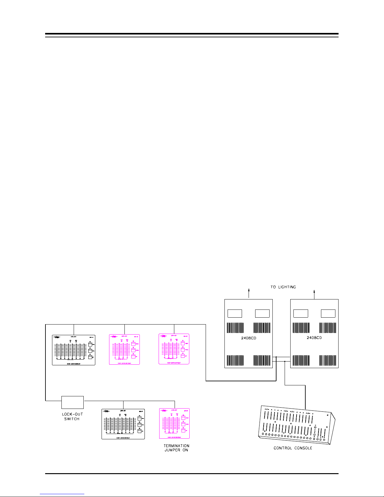
The 804CP and 808CP may be connected to the dimming system via parallel or daisy-chained wiring. Due to
power supply current demands, panels must be limited to 5 units per daisy chain run with 22 awg wire, or 10
units with 20 AWG wire.
The Luma-net panels feature plug on wiring terminals. The terminals may be unplugged from the panel to facilitate
ease of wiring and testing. Connect the terminals marked remote+, remote-, common, and +15 VDC to the same
respective terminals on the dimming system and other Luma-net panels. Use one twisted pair for remote+ and
remote- and the other pair for common and +15 VDC.
The wiring to the remote lockout switch, if used, can be simple 2 conductor 22 AWG. Connect the wires from
the switch to the lockout+ and lockout- terminals. Any panel or group of panels may be locked-out remotely by
interrupting the +15V supply to the panels. This should not affect any other panels still powered, or affect lighting
levels currently set.
IMPORTANT: Verify wiring is correct before powering system! Make sure nothing conductive may touch
pc board or components!
MOUNTING
The 804CP and will mount in any standard double-gang electrical box, while the 808CP will mount in a large
three-gang box with the 4 screws provided. See below paragraph on system turn-on before final mounting of
panels.
SYSTEM TURN-ON
It is very important that the system operation be verified one panel at a time. Else, an improper connection at
one panel would cause the entire system to not operate properly and may be difficult to diagnose.
After all terminal plugs have been wired and the dimmer system has been installed and tested, the installer is ready
to connect each panel to the system. Panels may be plugged-in while system is live, but the installer must take
care not to touch PC board or connections with fingers or metal objects. On daisy-chain runs, the panels closest
to the dimming system should be connected first.
804CP and 808CP panels have dip switches to set network ID number and must have their ID programmed before
the system power is connected. It is recommended that the installer review the programming procedures for
network ID before proceding. A duplicate network ID number will cause the entire network to malfunction.
Connect the first panel and immediately notice whether the POWER LED comes on, indicating power to the
panel. The BUSY LED should come on momentarily and then go out and stay out. This indicates a successful
reconfiguration of the network. If the BUSY LED flashes slowly, this indicates a duplicate ID number or wiring
problem. Program the ID number, if not already, and observe the BUSY LED. (Note, the busy LED also flashes
quickly when the program jumper is removed).
Now test the dimmer function by operating the panel. If the dimmer responds, then mount the panel and procede
to the next panel in the system and follow the same procedure.
NSI CORPORATION 2
REMOTE CONTROL PANEL
Software Revision 3.00, Version C LEDS
LEDS
The PWR LED indicates the presence of +15VDC to the panel.
The CONTROL ACTIVE green LED’s indicate that the panel has control over any dimmers assigned
to the repective zone and the dimmer levels have not been altered by any other panel. The LED will
go out as soon as another panel changes the levels of any dimmer assigned to that particular zone.
The BUSY LED indicates the following:
Off Normal state when there is no activity.
Short Blinks A message is being sent on the network.
Steady on or Slow flashing Network trying to reconfigure (bad ID?)
While programming, the following actions are normal.
Quickly flashing Programming mode.
LOCKOUT
Any 804CP and 808CP may be disabled from operation with a remote key switch or other contact closure. Several
Luma-net panels of the same version may be connected to the same contacts in parallel as long as polarity is
maintained.
Closing the contact will prevent connected panels from operating, regardless of button presses.
Luma-net panels may also be locked out by causing a switch to disconnect the +15V supply to the panels.
NSI CORPORATION 3
 Loading...