

NSI 2408CD, 2408 Installation And Operation Manual

2408 CD I
CR DIMMER SYSTEM
2408 CD
CR DIMMER SYSTEM
Software Revision 2.0, Version C
INTRODUCTION
The NSI 2408 dimmer represents a key part of a state of the art, total lighti
ng control system. Combined
with either NSI remote control panels and / or an NSI memory control console, a totally integrated
system is achieved.
The 2408 provides eight channels of 2400 watts each. This dimmer is designed to be permanently
control of house or stage lighting in schools, churches, theaters, buildings, etc. Several
remote control panels such as the NSI 400CP may be mounted at doorways, or other locations at which
ory control console or other suitable
console may be added to the system for special lighting effects. Several 2408 dimmer packs may be
combined for more channels or circuits of lighting.
Number of Channels:
el (20A 120VAC)
Output capacity:
Pressure type screw terminals (CU wiring
Load fi1tering: Control
512 digital signal (512 channel).
NSI's remote control digital signal (512 channel).
Pressure type screw terminals. Passive
Software Revision 2.0, Version C
/
INSTALLATION AND OPERATION GUIDE
installed for
dimmer control is desired. For entertainment lighting; an NSI mem
INTRODUCTION
SPECIFICATIONS
Input Power:
Line and Load connectors:
Input Types:
Control Wiring:
Control Connections:
Cooling System:
8 (4 for 2404)
2400 watts \ chann
120/240VAC or 120/208VAC 80A
only).
400us rise time torroids. (CR models only).
0 -10VDC each channel.
DMX-
MICROPLEX multiplex signal (128 channel).
Class 2 low voltage.
aluminum fins.
Page 1 of 10
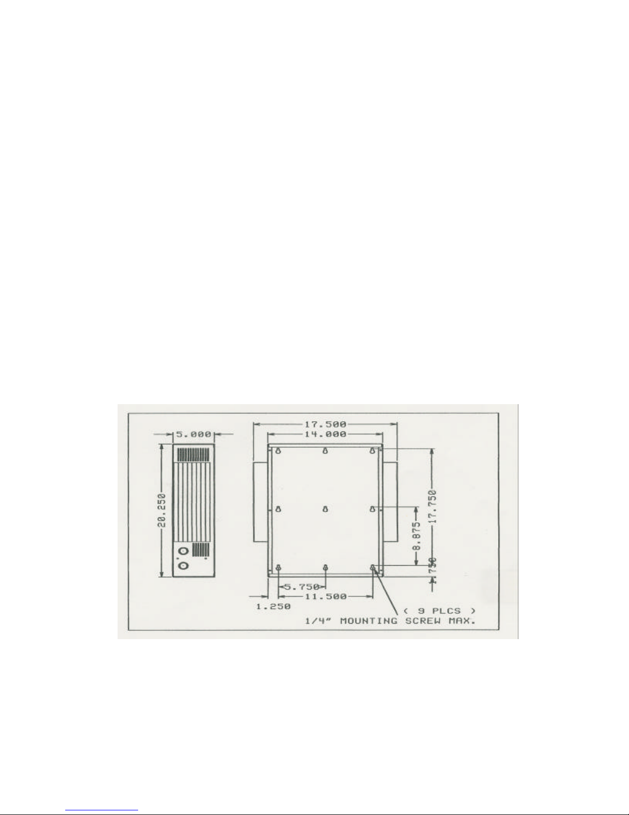
MOUNTING
The 2408 CD Dimmer pack or 2408 CR Relay pack must be mounted securely in a dry location
manner which is capable of supporting
hole" type mounting holes for 1/4" lag screws are provided in the back
wall of the unit for this purpose. See diagram for hole locations.
Since the 2408 CD/CR depends upon convection cooling, room airflow must not be prevented
side and top clearances from adjacent walls and
equipment are necessary:
enclosed room, adequate ventilation must be
working space and access to the 2408 CD/CR must be provided in accordance with
MOUNTING Software Revision 2.0, Version C
to the surface of a wall or other vertical flat surface in a
it's weight. Nine "key-
by walls or other obstructions. Adequate
Minimum distance from top to ceiling:
Minimum distance from top to other equipment:
Minimum distance from side adjacent to wall:
Minimum distance from side to other equipment:
If several units are to be installed in a small-
provided to prevent the room temperature from exceeding 100 degrees Fahrenheit.
36"
12"
12"
6"
2408 CD / CR DIMMER SYSTEM
Clear
electrical codes.
Page 2 of 10
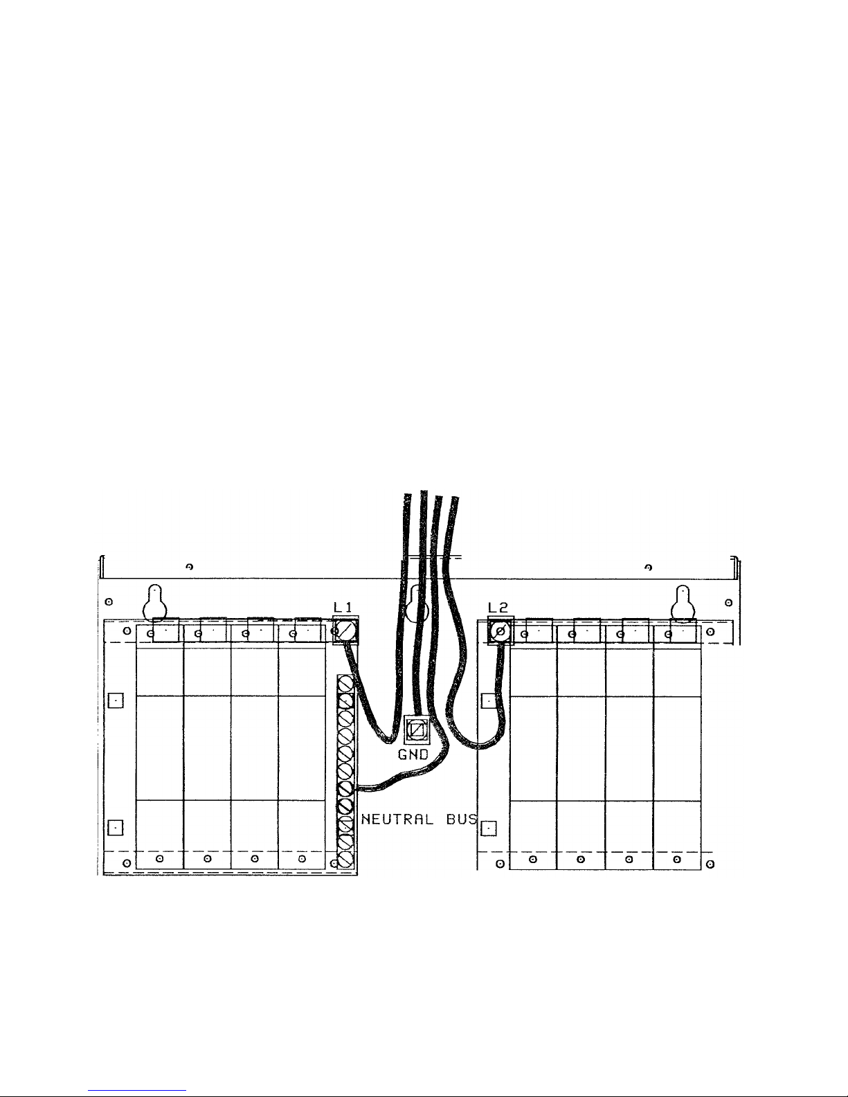
INPUT WIRING
The 2408 CD/CR must be provided with an 80 amp, 120/240 or
l20/208Y VAC, three wire
electrical service. This service must include two live wires not exceeding 150 volts to ground
and one neutral wire.
In addition the unit must be grounded by conduit or an additional ground wire in accordance with
electrical codes.
The input wiring should be #4 AWG THWN or equivalent copper wire rated for least 75 C.
Pass the input wiring through the 1 1/4" conduit hole in the top of the unit. Allow the wires to drop 4
-
6"
2). Connect each of the two live wires to the
copper lugs located above the circuit breakers and connect the neutral wire to the neutral bar .If provided,
connect the additional ground wire to the terminal marked "GND".
2408 CD / CR DIMMER SYSTEM
Software Revision 2-0, Version C INPUT WIRING
into the unit then loop the wires back upwards (see diagram #
120/24O or 120/200 80A
-------------------------------------------------------------------------------
----------------------------------------------------------------------------
20 AMP CIRCUIT BREAKERS
20 AMP CIRCUIT BREAKERS
Page 3 of 10
 Loading...