

NSC LMH6624MFX, LMH6624MF, LMH6624MDC, LMH6624MAX, LMH6624MA Datasheet
LMH6624/LMH6626
Single/Dual Ultra Low Noise Wideband Operational
Amplifier
General Description
The LMH6624/LMH6626 offer wide bandwidth (1.5GHz for
single, 1.3GHz for dual) with very low input noise (0.92nV/
, 2.3pA/ ) and ultra low dc errors (100µV VOS,
±
0.1µV/˚C drift) providing very precise operational amplifiers
with wide dynamic range. This enables the user to achieve
closed-loop gains of greater than 10, in both inverting and
non-inverting configurations.
The LMH6624 (single) and LMH6626’s (dual) traditional voltage feedback topology provide the following benefits: balanced inputs, low offset voltage and offset current, very low
offset drift, 81dB open loop gain, 95dB common mode rejection ratio, and 88dB power supply rejection ratio.
The LMH6624/LMH6626 operate from
±
2.5V to±6V in
dual supply mode and from +5V to +12V in single supply
configuration.
LMH6624 is offered in SOT23-5 and SOIC-8 packages.
The LMH6626 is offered in SOIC-8 and MSOP-8 packages.
Features
VS=±6V, TA= 25˚C, AV= 20, (Typical values unless
specified)
n Gain bandwidth (LMH6624) 1.5GHz
n Input voltage noise 0.92nV/
n Input offset voltage (limit over temp) 700uV
n Slew rate 350V/µs
n Slew rate (A
V
= 10) 400V/µs
n HD2
@
f = 10MHz, RL= 100Ω −63dBc
n HD3
@
f = 10MHz, RL= 100Ω −80dBc
n Supply voltage range (dual supply)
±
2.5V to±6V
n Supply voltage range (single supply) +5V to +12V
n Improved replacement for the CLC425 (LMH6624)
n Stable for closed loop |A
V
| ≥ 10
Applications
n Instrumentation sense amplifiers
n Ultrasound pre-amps
n Magnetic tape & disk pre-amps
n Wide band active filters
n Professional Audio Systems
n Opto-electronics
n Medical diagnostic systems
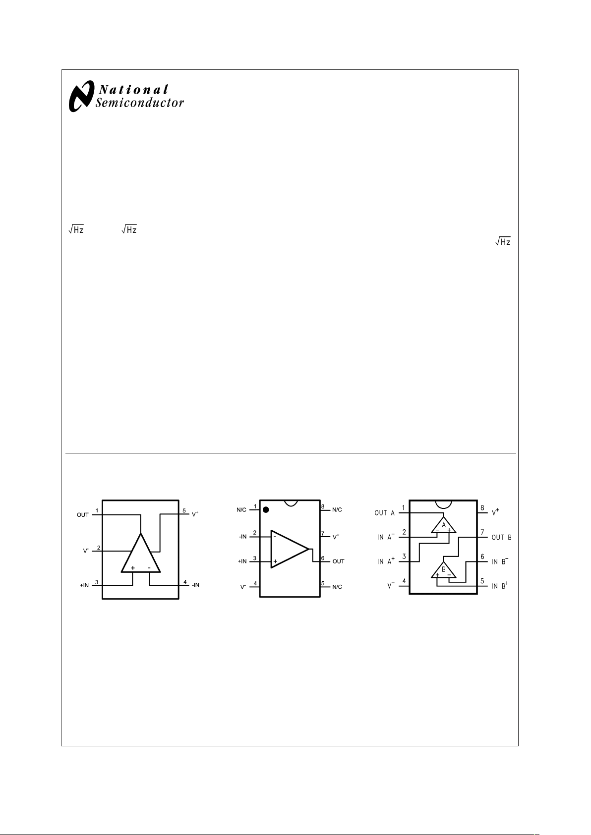
Connection Diagrams
5-Pin SOT23 8−Pin SOIC 8−Pin SOIC/MSOP
20058951
Top View
20058952
Top View
20058961
Top View
May 2003
LMH6624/LMH6626 Single/Dual Ultra Low Noise Wideband Operational Amplifier
© 2003 National Semiconductor Corporation DS200589 www.national.com
Absolute Maximum Ratings (Note 1)
If Military/Aerospace specified devices are required,
please contact the National Semiconductor Sales Office/
Distributors for availability and specifications.
ESD Tolerance
Human Body Model 2000V (Note 2)
Machine Model 200V (Note 9)
V
IN
Differential
±
1.2V
Supply Voltage (V
+-V−
) 13.2V
Voltage at Input pins V
+
+0.5V, V−−0.5V
Soldering Information
Infrared or Convection (20 sec.) 235˚C
Wave Soldering (10 sec.) 260˚C
Storage Temperature Range −65˚C to +150˚C
Junction Temperature (Note 3), (Note 4) +150˚C
Operating Ratings (Note 1)
Operating Temperature Range
(Note 3), (Note 4) −40˚C to +125˚C
Package Thermal Resistance (θ
JA
)(Note 4)
SOIC-8 166˚C/W
SOT23–5 265˚C/W
MSOP-8 235˚C/W
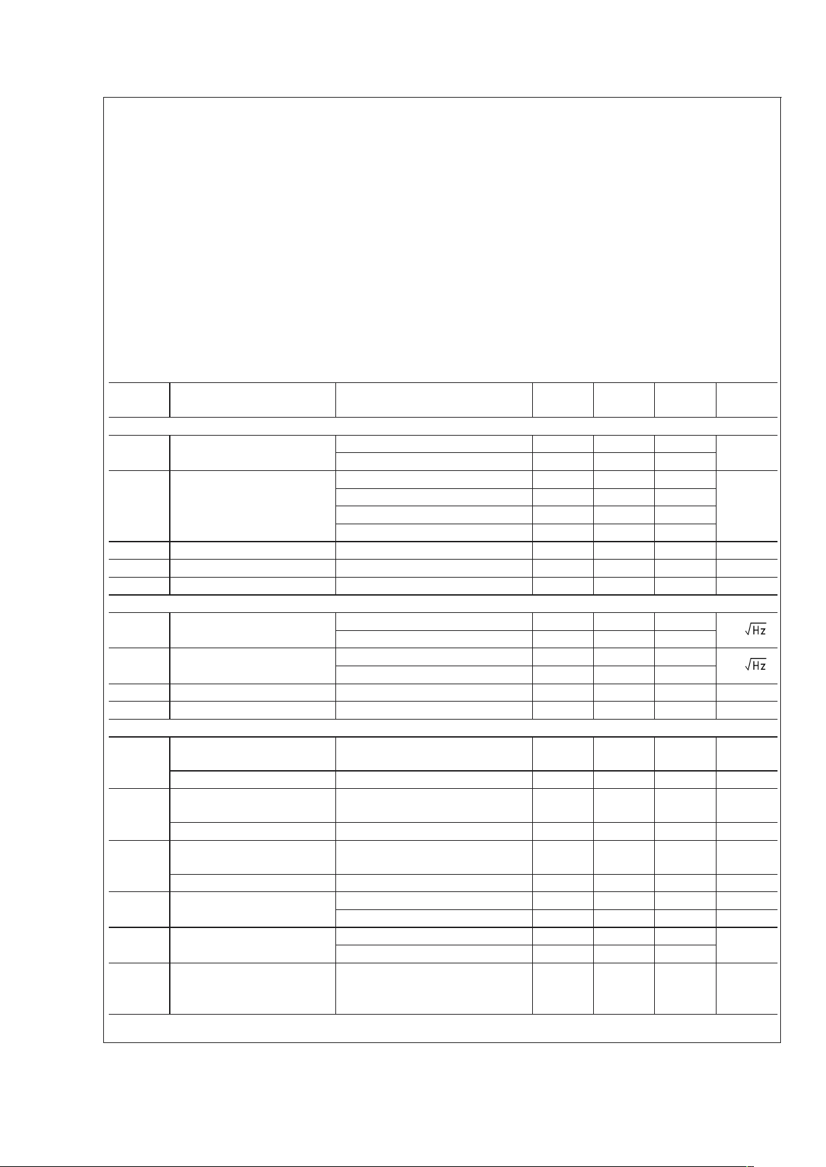
±
2.5V Electrical Characteristics
Unless otherwise specified, all limits guaranteed at TA= 25˚C, V+= 2.5V, V−= −2.5V, VCM= 0V, AV= +20, RF= 500Ω,RL=
100Ω. Boldface limits apply at the temperature extremes. See (Note 12).
Symbol Parameter Conditions Min
(Note 6)
Typ
(Note 5)
Max
(Note 6)
Units
Dynamic Performance
f
CL
−3dB BW VO= 400mVPP(LMH6624) 90
MHz
V
O
= 400mVPP(LMH6626) 80
SR Slew Rate(Note 8) V
O
=2VPP,AV= +20 (LMH6624) 300
V/µs
V
O
=2VPP,AV= +20 (LMH6626) 290
V
O
=2VPP,AV= +10 (LMH6624) 360
V
O
=2VPP,AV= +10 (LMH6626) 340
t
r
Rise Time VO= 400mV Step, 10% to 90% 4.1 ns
t
f
Fall Time VO= 400mV Step, 10% to 90% 4.1 ns
t
s
Settling Time 0.1% VO=2VPP(Step) 20 ns
Distortion and Noise Response
e
n
Input Referred Voltage Noise f = 1MHz (LMH6624) 0.92
nV/
f = 1MHz (LMH6626) 1.0
i
n
Input Referred Current Noise f = 1MHz (LMH6624) 2.3
pA/
f = 1MHz (LMH6626) 1.8
HD2 2
nd
Harmonic Distortion fC= 10MHz, VO=1VPP,RL100Ω −60 dBc
HD3 3
rd
Harmonic Distortion fC= 10MHz, VO=1VPP,RL100Ω −76 dBc
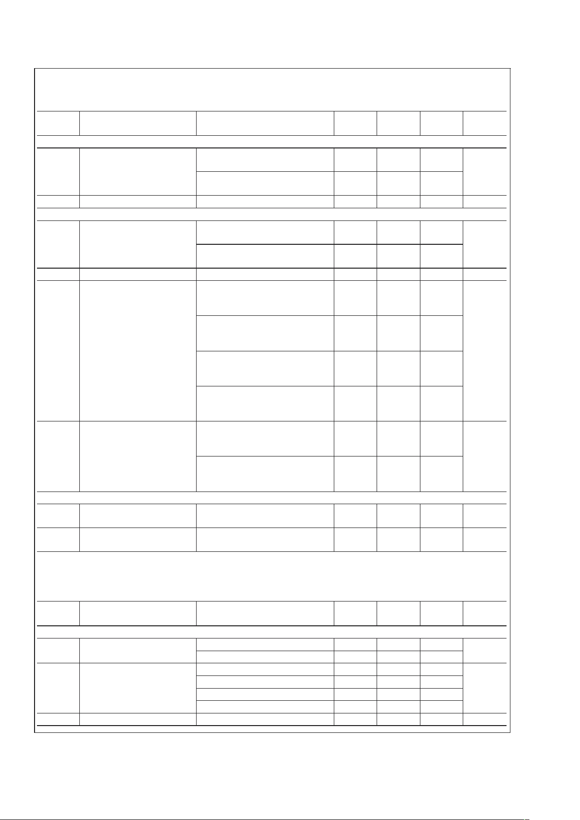
Input Characteristics
V
OS
Input Offset Voltage VCM= 0V −0.75
−0.95
−0.25 +0.75
+0.95
mV
Average Drift (Note 7) VCM=0V
±
0.25 µV/˚C
I
OS
Input Offset Current VCM= 0V −1.5
−2.0
−0.05 +1.5
+2.0
µA
Average Drift (Note 7) V
CM
= 0V 2 nA/˚C
I
B
Input Bias Current VCM= 0V 13 +20
+25
µA
Average Drift (Note 7) VCM= 0V 12 nA/˚C
R
IN
Input Resistance (Note 10) Common Mode 6.6 MΩ
Differential Mode 4.6 kΩ
C
IN
Input Capacitance (Note 10) Common Mode 0.9 pF
Differential Mode 2.0
CMRR Common Mode Rejection
Ratio
Input Referred,
dB
V
CM
= −0.5 to +1.9V
V
CM
= −0.5 to +1.75V
87
85
90
LMH6624/LMH6626
www.national.com 2
±
2.5V Electrical Characteristics (Continued)
Unless otherwise specified, all limits guaranteed at TA= 25˚C, V+= 2.5V, V−= −2.5V, VCM= 0V, AV= +20, RF= 500Ω,RL=
100Ω. Boldface limits apply at the temperature extremes. See (Note 12).
Symbol Parameter Conditions Min
(Note 6)
Typ
(Note 5)
Max
(Note 6)
Units
Transfer Characteristics
A
VOL
Large Signal Voltage Gain (LMH6624)
R
L
= 100Ω,VO= −1V to +1V
75
70
79
dB
(LMH6626)
R
L
= 100Ω,VO= −1V to +1V
72
67
79
X
t
Crosstalk Rejection f = 1MHz (LMH6626) −75 dB
Output Characteristics
V
O
Output Swing RL= 100Ω
±
1.1
±
1.0
±
1.5
V
No Load
±
1.4
±
1.25
±
1.7
R
O
Output Impedance f ≤ 100KHz 10 mΩ
I
SC
Output Short Circuit Current (LMH6624)
Sourcing to Ground
∆V
IN
= 200mV (Note 3), (Note 11)
90
75
145
mA
(LMH6624)
Sinking to Ground
∆V
IN
= −200mV (Note 3), (Note 11)
90
75
145
(LMH6626)
Sourcing to Ground
∆V
IN
= 200mV (Note 3),(Note 11)
60
50
120
(LMH6626)
Sinking to Ground
∆V
IN
= −200mV (Note 3),(Note 11)
60
50
120
I
OUT
Output Current (LMH6624)
Sourcing, V
O
= +0.8V
Sinking, V
O
= −0.8V
100
mA
(LMH6626)
Sourcing, V
O
= +0.8V
Sinking, V
O
= −0.8V
75
Power Supply
PSRR Power Supply Rejection Ratio V
S
=±2.0V to±3.0V 82
80
90 dB
I
S
Supply Current (per channel) No Load 11.4 16
18
mA
±
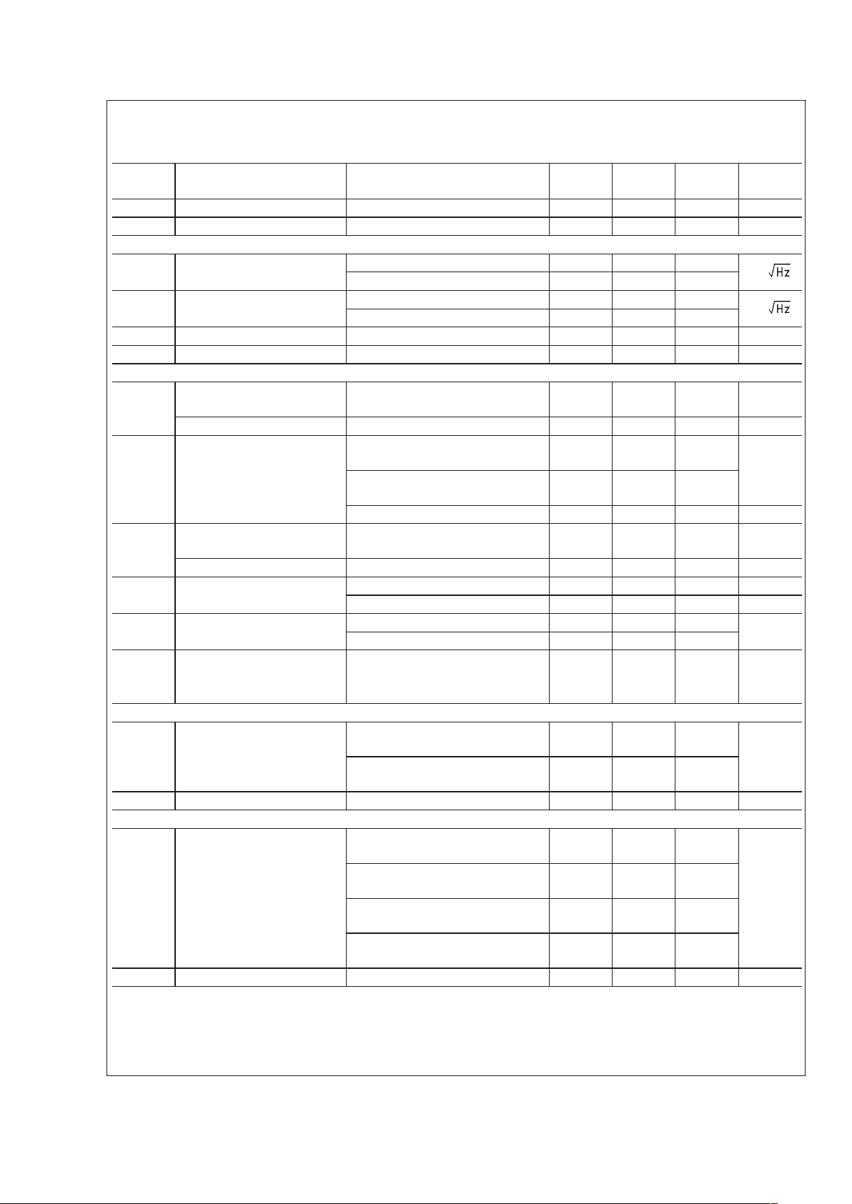
6V Electrical Characteristics
Unless otherwise specified, all limits guaranteed at TA= 25˚C, V+= 6V, V−= −6V, VCM= 0V, AV= +20, RF= 500Ω,RL=
100Ω. Boldface limits apply at the temperature extremes. See (Note 12).
Symbol Parameter Conditions Min
(Note 6)
Typ
(Note 5)
Max
(Note 6)
Units
Dynamic Performance
f
CL
−3dB BW VO= 400mVPP(LMH6624) 95
MHz
V
O
= 400mVPP(LMH6626) 85
SR Slew Rate (Note 8) V
O
=2VPP,AV= +20 (LMH6624) 350
V/µs
V
O
=2VPP,AV= +20 (LMH6626) 320
V
O
=2VPP,AV= +10 (LMH6624) 400
V
O
=2VPP,AV= +10 (LMH6626) 360
t
r
Rise Time VO= 400mV Step, 10% to 90% 3.7 ns
LMH6624/LMH6626
www.national.com3
±
6V Electrical Characteristics (Continued)
Unless otherwise specified, all limits guaranteed at TA= 25˚C, V+= 6V, V−= −6V, VCM= 0V, AV= +20, RF= 500Ω,RL=
100Ω. Boldface limits apply at the temperature extremes. See (Note 12).
Symbol Parameter Conditions Min
(Note 6)
Typ
(Note 5)
Max
(Note 6)
Units
t
f
Fall Time VO= 400mV Step, 10% to 90% 3.7 ns
t
s
Settling Time 0.1% VO=2VPP(Step) 18 ns
Distortion and Noise Response
e
n
Input Referred Voltage Noise f = 1MHz (LMH6624) 0.92
nV/
f = 1MHz (LMH6626) 1.0
i
n
Input Referred Current Noise f = 1MHz (LMH6624) 2.3
pA/
f = 1MHz (LMH6626) 1.8
HD2 2
nd
Harmonic Distortion fC= 10MHz, VO=1VPP,RL100Ω −63 dBc
HD3 3
rd
Harmonic Distortion fC= 10MHz, VO=1VPP,RL100Ω −80 dBc
Input Characteristics
V
OS
Input Offset Voltage VCM= 0V −0.5
−0.7
±
0.10 +0.5
+0.7
mV
Average Drift (Note 7) V
CM
=0V
±
0.2 µV/˚C
I
OS
Input Offset Current Average
Drift (Note 7)
(LMH6624)
V
CM
=0V
−1.1
−2.5
0.05 1.1
2.5
µA
(LMH6626)
V
CM
=0V
−2.0
−2.5
0.1 2.0
2.5
V
CM
= 0V 0.7 nA/˚C
I
B
Input Bias Current VCM= 0V 13 +20
+25
µA
Average Drift (Note 7) VCM= 0V 12 nA/˚C
R
IN
Input Resistance (Note 10) Common Mode 6.6 MΩ
Differential Mode 4.6 kΩ
C
IN
Input Capacitance (Note 10) Common Mode 0.9
pF
Differential Mode 2.0
CMRR Common Mode Rejection
Ratio
Input Referred,
dB
V
CM
= −4.5 to +5.25V
V
CM
= −4.5 to +5.0V
90
87
95
Transfer Characteristics
A
VOL
Large Signal Voltage Gain (LMH6624)
R
L
= 100Ω,VO= −3V to +3V
77
72
81
dB
(LMH6626)
RL= 100Ω,VO= −3V to +3V
74
70
80
X
t
Crosstalk Rejection f = 1MHz (LMH6626) −75 dB
Output Characteristics
V
O
Output Swing (LMH6624)
R
L
= 100Ω
±
4.4
±
4.3
±
4.9
V
(LMH6624)
No Load
±
4.8
±
4.65
±
5.2
(LMH6626)
R
L
= 100Ω
±
4.3
±
4.2
±
4.8
(LMH6626)
No Load
±
4.8
±
4.65
±
5.2
R
O
Output Impedance f ≤ 100KHz 10 mΩ
LMH6624/LMH6626
www.national.com 4
±
6V Electrical Characteristics (Continued)
Unless otherwise specified, all limits guaranteed at TA= 25˚C, V+= 6V, V−= −6V, VCM= 0V, AV= +20, RF= 500Ω,RL=
100Ω. Boldface limits apply at the temperature extremes. See (Note 12).
Symbol Parameter Conditions Min
(Note 6)
Typ
(Note 5)
Max
(Note 6)
Units
I
SC
Output Short Circuit Current (LMH6624)
Sourcing to Ground
∆V
IN
= 200mV (Note 3), (Note 11)
100
85
156
mA
(LMH6624)
Sinking to Ground
∆V
IN
= −200mV (Note 3), (Note 11)
100
85
156
(LMH6626)
Sourcing to Ground
∆V
IN
= 200mV (Note 3), (Note 11)
65
55
120
(LMH6626)
Sinking to Ground
∆V
IN
= −200mV (Note 3), (Note 11)
65
55
120
I
OUT
Output Current (LMH6624)
Sourcing, V
O
= +4.3V
Sinking, V
O
= −4.3V
100
mA
(LMH6626)
Sourcing, V
O
= +4.3V
Sinking, V
O
= −4.3V
80
Power Supply
PSRR Power Supply Rejection Ratio V
S
=±5.4V to±6.6V 82
80
88 dB
I
S
Supply Current (per channel) No Load 12 16
18
mA
Note 1: Absolute maximum ratings indicate limits beyond which damage to the device may occur. Operating Ratings indicate conditions for which the device is
intended to be functional, but specific performance is not guaranteed. For guaranteed specifications and the test conditions, see the Electrical Characteristics.
Note 2: Human body model, 1.5kΩ in series with 100pF.
Note 3: Applies to both single-supply and split-supply operation. Continuous short circuit operation at elevated ambient temperature can result in exceeding the
maximum allowed junction temperature of 150˚C.
Note 4: The maximum power dissipation is a function of T
J(MAX)
, θJA, and TA. The maximum allowable power dissipation at any ambient temperature is
P
D
=(T
J(MAX)-TA
)/ θJA. All numbers apply for packages soldered directly onto a PC board.
Note 5: Typical Values represent the most likely parametric norm.
Note 6: All limits are guaranteed by testing or statistical analysis.
Note 7: Average drift is determined by dividing the change in parameter at temperature extremes into the total temperature change.
Note 8: Slew rate is the slowest of the rising and falling slew rates.
Note 9: Machine Model, 0Ω in series with 200pF.
Note 10: Simulation results.
Note 11: Short circuit test is a momentary test. Output short circuit duration is 1.5ms.
Note 12: Electrical table values apply only for factory testing conditions at the temperature indicated. Factory testing conditions result in very limited self-heating of
the device such that T
J=TA
. No guarantee of parametric performance is indicated in the electrical tables under conditions of internal self-heating where T
J
>
TA.
Absolute maximum ratings indicate junction temperature limits beyond which the device may be permanently degraded, either mechanically or electrically.
Ordering Information
Package Part Number Package Marking Transport Media NSC Drawing
SOT23-5 LMH6624MF A94A 1k Units Tape and Reel MF05A
LMH6624MFX 3k Units Tape and Reel
SOIC-8 LMH6624MA LMH6624MA 95 Units/Rail M08A
LMH6624MAX 2.5k Units Tape and Reel
SOIC-8 LMH6626MA LMH6626MA 95 Units/Rail M08A
LMH6626MAX 2.5k Units Tape and Reel
MSOP-8 LMH6626MM A98A 1k Units Tape and Reel MUA08A
LMH6626MMX 3.5k Units Tape and Reel
LMH6624/LMH6626
www.national.com5
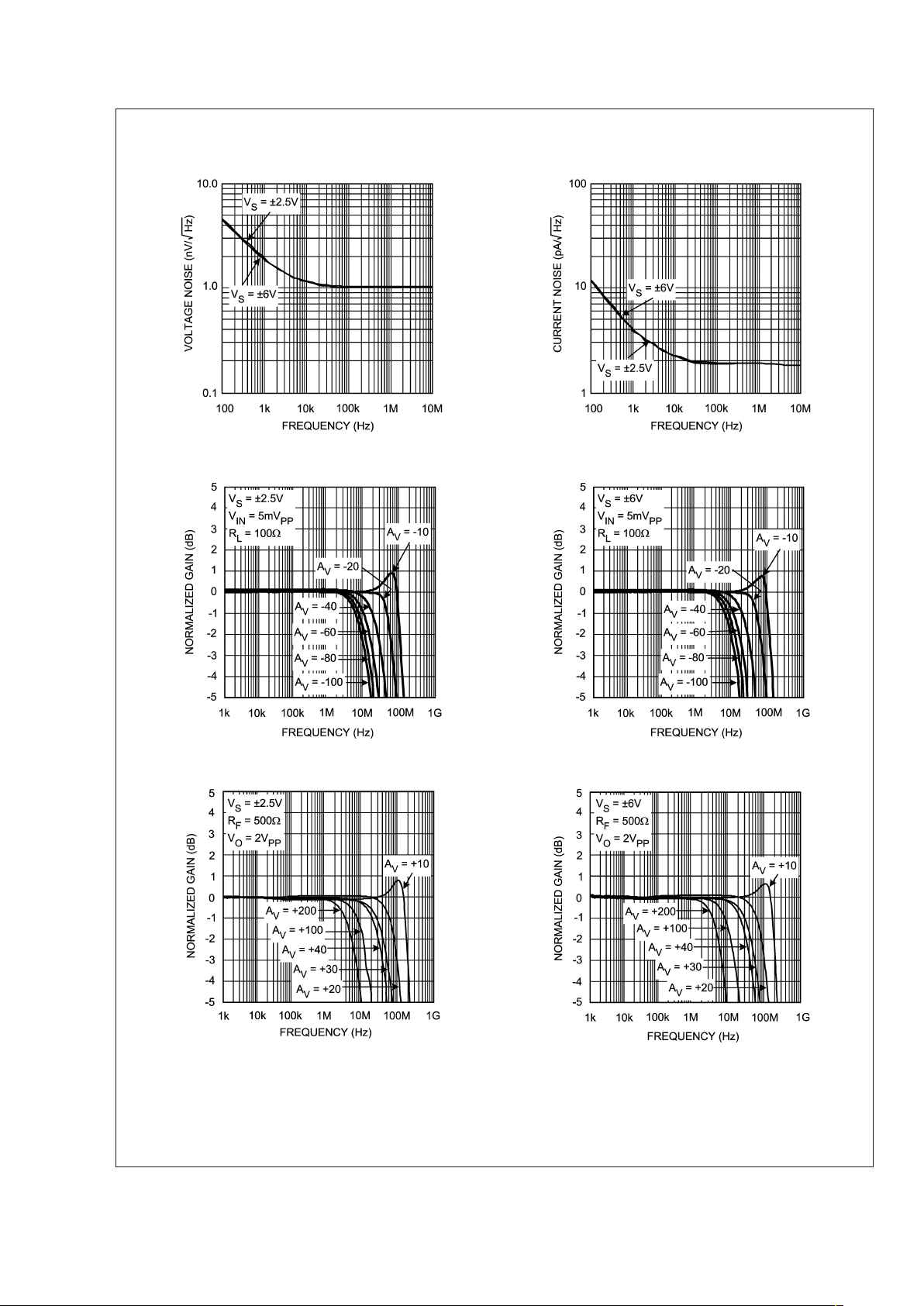
Typical Performance Characteristics
Voltage Noise vs. Frequency Current Noise vs. Frequency
20058962 20058963
Inverting Frequency Response Inverting Frequency Response
20058989 20058988
Non-Inverting Frequency Response Non-Inverting Frequency Response
20058904
20058903
LMH6624/LMH6626
www.national.com 6
 Loading...