

LM134/LM234/LM334
3-Terminal Adjustable Current Sources
General Description
The LM134/LM234/LM334 are 3-terminal adjustable current
sources featuring10,000:1 range in operating current, excellent current regulation and a wide dynamic voltage range of
1V to 40V. Current is established with one external resistor
and no other parts are required. Initial current accuracy is
±
3%. The LM134/LM234/LM334 are true floating current
sources with no separate power supply connections. In addition, reverse applied voltages of up to 20V will draw only a
few dozen microamperes of current, allowing the devices to
act as both a rectifier and current source in AC applications.
The sense voltage used to establish operating current in the
LM134 is 64mV at 25˚C and is directly proportional to absolute temperature (˚K). The simplest one external resistor
connection, then, generates a current with ≈+0.33%/˚C temperature dependence. Zero drift operation can be obtained
by adding one extra resistor and a diode.
Applications for the current sources include bias networks,
surge protection, low power reference, ramp generation,
LED driver, and temperature sensing. The LM234-3 and
LM234-6 are specified as true temperature sensors with
guaranteed initial accuracy of
±
3˚C and±6˚C, respectively.
These devices are ideal in remote sense applications because series resistance in long wire runs does not affect
accuracy. In addition, only 2 wires are required.
The LM134 is guaranteed over a temperature range of
−55˚C to +125˚C, the LM234 from −25˚C to +100˚C and the
LM334 from 0˚C to +70˚C. These devices are available in
TO-46 hermetic, TO-92 and SO-8 plastic packages.
Features
n Operates from 1V to 40V
n 0.02%/V current regulation
n Programmable from 1µA to 10mA
n True 2-terminal operation
n Available as fully specified temperature sensor
n
±
3% initial accuracy
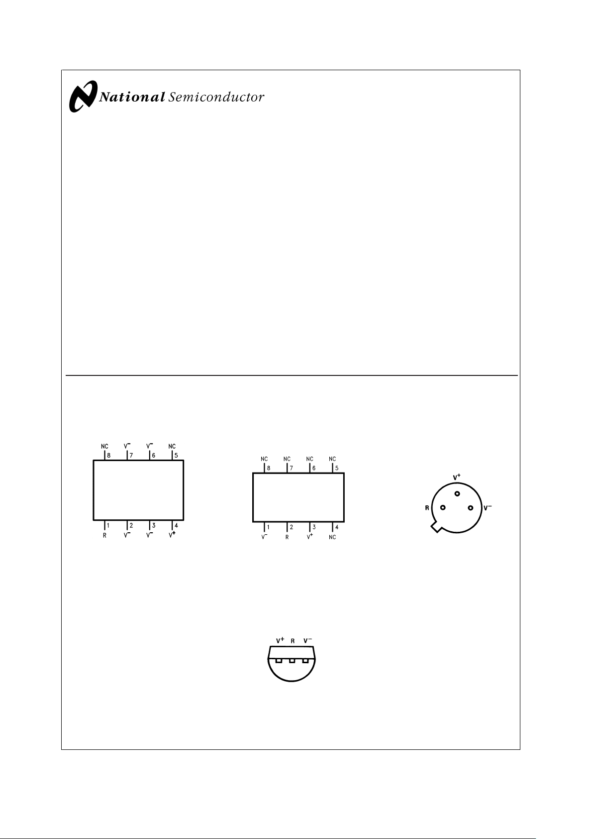
Connection Diagrams
SO-8
Surface Mount Package
DS005697-24
Order Number LM334M or
LM334MX
See NS Package Number M08A
SO-8 Alternative Pinout
Surface Mount Package
DS005697-25
Order Number LM334SM or
LM334SMX
See NS Package Number M08A
TO-46
Metal Can Package
DS005697-12
V−Pin is electrically connected to case.
Bottom View
Order Number LM134H,
LM234H or LM334H
See NS Package
Number H03H
TO-92 Plastic Package
DS005697-10
Bottom View
Order Number LM334Z, LM234Z-3 or LM234Z-6
See NS Package Number Z03A
March 2000
LM134/LM234/LM334 3-Terminal Adjustable Current Sources
© 2001 National Semiconductor Corporation DS005697 www.national.com
Absolute Maximum Ratings (Note 1)
If Military/Aerospace specified devices are required,
please contact the National Semiconductor Sales Office/
Distributors for availability and specifications.
V
+
to V−Forward Voltage
LM134/LM234/LM334 40V
LM234-3/LM234-6 30V
V
+
to V−Reverse Voltage 20V
R Pin to V
−
Voltage 5V
Set Current 10 mA
Power Dissipation 400 mW
ESD Susceptibility (Note 6) 2000V
Operating Temperature Range (Note 5)
LM134 −55˚C to +125˚C
LM234/LM234-3/LM234-6 −25˚C to +100˚C
LM334 0˚C to +70˚C
Soldering Information
TO-92 Package (10 sec.) 260˚C
TO-46 Package (10 sec.) 300˚C
SO Package
Vapor Phase (60 sec.) 215˚C
Infrared (15 sec.) 220˚C
See AN-450 “Surface Mounting Methods and Their Effect on
Product Reliability” (Appendix D) for other methods of soldering surface mount devices.
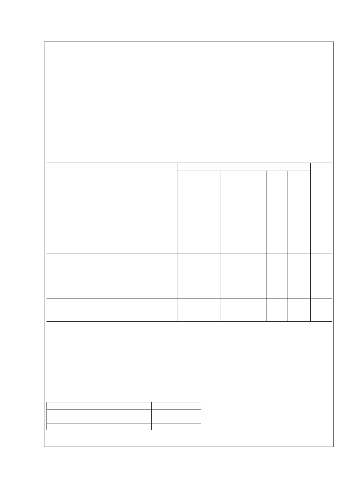
Electrical Characteristics (Note 2)
Parameter Conditions LM134/LM234 LM334 Units
Min Typ Max Min Typ Max
Set Current Error, V
+
=2.5V, 10µA ≤ I
SET
≤ 1mA 3 6 %
(Note 3) 1mA
<
I
SET
≤ 5mA 5 8 %
2µA ≤ I
SET
<
10µA 8 12 %
Ratio of Set Current to 100µA ≤ I
SET
≤ 1mA 14 18 23 14 18 26
Bias Current 1mA ≤ I
SET
≤ 5mA 14 14
2µA≤I
SET
≤100 µA 18 23 18 26
Minimum Operating Voltage 2µA ≤ I
SET
≤ 100µA 0.8 0.8 V
100µA
<
I
SET
≤
1mA
0.9 0.9 V
1mA
<
I
SET
≤ 5mA 1.0 1.0 V
Average Change in Set Current 2µA ≤ I
SET
≤ 1mA
with Input Voltage 1.5 ≤ V
+
≤ 5V 0.02 0.05 0.02 0.1 %/V
5V ≤ V
+
≤ 40V 0.01 0.03 0.01 0.05 %/V
1mA
<
I
SET
≤ 5mA
1.5V ≤ V ≤ 5V 0.03 0.03 %/V
5V ≤ V ≤ 40V 0.02 0.02 %/V
Temperature Dependence of 25µA ≤ I
SET
≤ 1mA 0.96T T 1.04T 0.96T T 1.04T
Set Current (Note 4)
Effective Shunt Capacitance 15 15 pF
Note 1: .“Absolute Maximum Ratings” indicate limits beyond which damage to the device may occur. Operating Ratings indicate conditions for which the device is
functional, but do not guarantee specific performance limits.
Note 2: Unless otherwise specified, tests are performed at T
j
= 25˚C with pulse testing so that junction temperature does not change during test
Note 3: Set current is the current flowing into the V
+
pin. For the Basic 2-Terminal Current Source circuit shown on the first page of this data sheet. I
SET
is
determined by the following formula: I
SET
= 67.7 mV/R
SET
(@25˚C). Set current error is expressed as a percent deviation from this amount. I
SET
increases at
0.336%/˚C
@
Tj= 25˚C (227 µV/˚C).
Note 4: I
SET
is directly proportional to absolute temperature (˚K). I
SET
at any temperature can be calculated from: I
SET=Io
(T/To) where Iois I
SET
measured at T
o
(˚K).
Note 5: For elevated temperature operation, T
J
max is:
LM134 150˚C
LM234 125˚C
LM334 100˚C
Thermal Resistance TO-92 TO-46 SO-8
θ
ja
(Junction to Ambient) 180˚C/W (0.4" leads) 440˚C/W 165˚C/W
160˚C/W (0.125" leads)
θ
jc
(Junction to Case) N/A 32˚C/W 80˚C/W
Note 6: Human body model, 100pF discharged through a 1.5kΩ resistor.
LM134/LM234/LM334
www.national.com 2
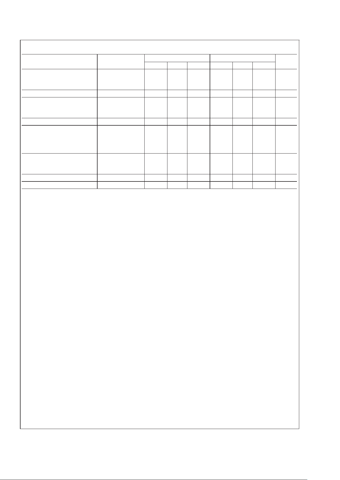
Electrical Characteristics (Note 2)
Parameter Conditions LM234-3 LM234-6 Units
Min Typ Max Min Typ Max
Set Current Error, V
+
=2.5V, 100µA ≤ I
SET
≤
1mA
±
1
±
2%
(Note 3) T
J
= 25˚
Equivalent Temperature Error
±
3
±
6˚C
Ratio of Set Current to 100µA ≤ I
SET
≤
1mA
14 18 26 14 18 26
Bias Current
Minimum Operating Voltage 100µA I
SET
≤ 1mA 0.9 0.9 V
Average Change in Set Current 100µA ≤ I
SET
≤
1mA
with Input Voltage 1.5 ≤ V
+
≤ 5V 0.02 0.05 0.02 0.01 %/V
5V ≤ V
+
≤ 30V 0.01 0.03 0.01 0.05 %/V
Temperature Dependence of 100µA ≤ I
SET
≤
1mA
0.98T T 1.02T 0.97T T 1.03T
Set Current (Note 4) and
Equivalent Slope Error
±
2
±
3%
Effective Shunt Capacitance 15 15 pF
LM134/LM234/LM334
www.national.com3
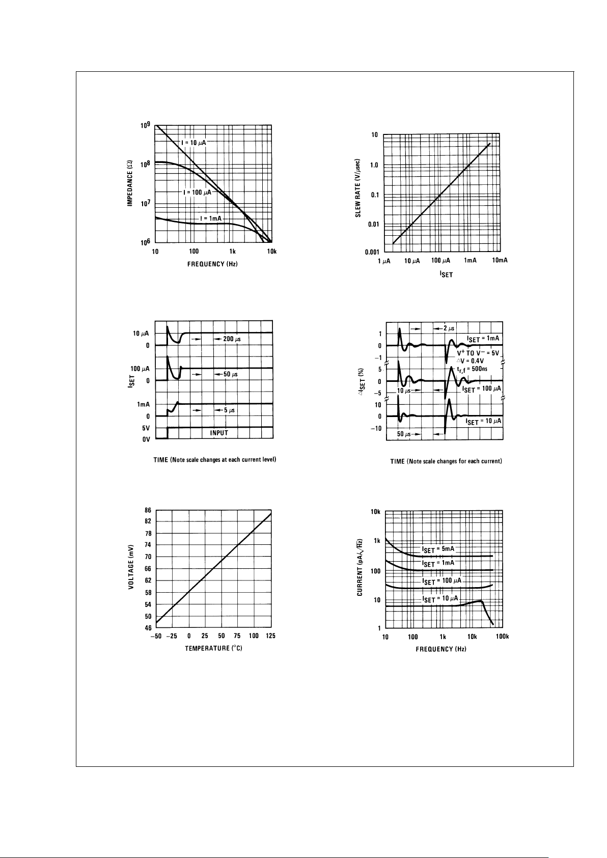
Typical Performance Characteristics
Output Impedance
DS005697-30
Maximum Slew Rate
Linear Operation
DS005697-31
Start-Up
DS005697-32
Transient Response
DS005697-33
Voltage Across R
SET(VR
)
DS005697-34
Current Noise
DS005697-35
LM134/LM234/LM334
www.national.com 4
Typical Performance Characteristics (Continued)
Application Hints
The LM134 has been designed for ease of application, but a
general discussion of design features is presented here to
familiarize the designer with device characteristics which
may not be immediately obvious. These include the effects
of slewing, power dissipation, capacitance, noise, and contact resistance.
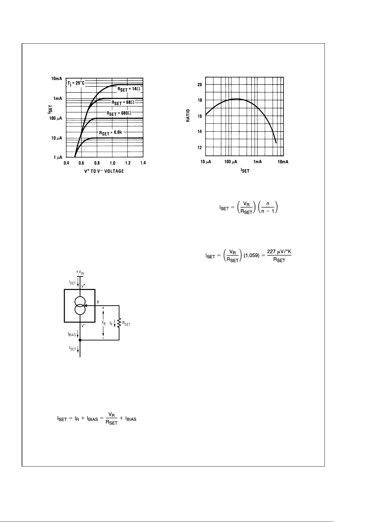
CALCULATING R
SET
The total current through the LM134 (I
SET
) is the sum of the
current going through the SET resistor (I
R
) and the LM134’s
bias current (I
BIAS
), as shown in
Figure 1
.
A graph showing the ratio of these two currents is supplied
under Ratio of I
SET
to I
BIAS
in the Typical Performance
Characteristics section. The current flowing through R
SET
is
determined by V
R
, which is approximately 214µV/˚K (64
mV/298˚K ∼ 214µV/˚K).
Since (for a given set current) I
BIAS
is simply a percentage of
I
SET
, the equation can be rewritten
where n is the ratio of I
SET
to I
BIAS
as specified in the
Electrical Characteristics Section and shown in the graph.
Since n is typically 18 for 2µA≤ I
SET
≤ 1mA, the equation can
be further simplified to
for most set currents.
SLEW RATE
At slew rates above a given threshold (see curve), the
LM134 may exhibit non-linear current shifts. The slewing
rate at which this occurs is directly proportional to I
SET
.At
I
SET
= 10µA, maximum dV/dt is 0.01V/µs; at I
SET
= 1mA, the
limit is 1V/µs. Slew rates above the limit do not harm the
LM134, or cause large currents to flow.
THERMAL EFFECTS
Internal heating can have a significant effect on current
regulation for I
SET
greater than 100µA. For example, each
1V increase across the LM134 at I
SET
= 1 mA will increase
junction temperature by ≈0.4˚C in still air. Output current
(I
SET
) has a temperature coefficient of ≈0.33%/˚C, so the
change in current due to temperature rise will be (0.4)
(0.33) = 0.132%. This is a 10:1 degradation in regulation
compared to true electrical effects. Thermal effects, therefore, must be taken into account when DC regulation is
critical and I
SET
exceeds 100µA. Heat sinking of the TO-46
package or the TO-92 leads can reduce this effect by more
than 3:1.
SHUNT CAPACITANCE
In certain applications, the 15 pF shunt capacitance of the
LM134 may have to be reduced, either because of loading
problems or because it limitsthe AC outputimpedance of the
current source. This can be easily accomplished by buffering
the LM134 with an FET as shown in the applications. This
can reduce capacitance to less than 3 pF and improve
Turn-On Voltage
DS005697-29
Ratio of I
SET
to I
BIAS
DS005697-3
DS005697-27
FIGURE 1. Basic Current Source
LM134/LM234/LM334
www.national.com5
 Loading...