

LM2877 Dual 4W Audio Power Amplifier
LM2877 Dual 4W Audio Power Amplifier
February 1995
General Description
The LM2877 is a monolithic dual power amplifier designed
to deliver 4W/channel continuous into 8X loads. The
LM2877 is designed to operate with a low number of external components, and still provide flexibility for use in stereo
phonographs, tape recorders and AM-FM stereo receivers,
etc. Each power amplifier is biased from a common internal
regulator to provide high power supply rejection and output
Q point centering. The LM2877 is internally compensated
for all gains greater than 10, and comes in an 11-lead single-in-line package.
Features
Y
4W/channel
Y
b
68 dB ripple rejection, output referred
Y
b
70 dB channel separation, output referred
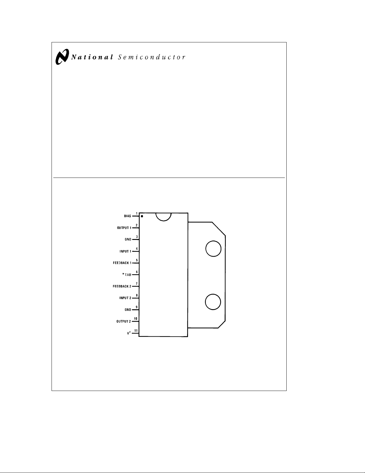
Connection Diagram
(Single-In-Line Package)
Y
Wide supply range, 6-24V
Y
Very low cross-over distortion
Y
Low audio band noise
Y
AC short circuit protected
Y
Internal thermal shutdown
Applications
Y
Multi-channel audio systems
Y
Stereo phonographs
Y
Tape recorders and players
Y
AM-FM radio receivers
Y
Servo amplifiers
Y
Intercom systems
Y
Automotive products
Top View
TL/H/7933– 1
Order Number LM2877P
See NS Package Number P11A
*Pin 6 must be connected to GND.
C
1995 National Semiconductor Corporation RRD-B30M75/Printed in U. S. A.
TL/H/7933

Absolute Maximum Ratings
If Military/Aerospace specified devices are required,
please contact the National Semiconductor Sales
Office/Distributors for availability and specifications.
Supply Voltage 26V
Ctoa70§C
§
e
20V, T
S
g
0.7V
TAB
Input Voltage
Operating Temperature 0
Electrical Characteristics V
Storage Temperature
Junction Temperature 150§C
Lead Temperature (Soldering, 10 sec.) 260§C
Thermal Resistance
i
JC
i
JA
e
25§C, R
e
L
8X,A
e
50 (34 dB) unless otherwise specified.
V
Parameter Conditions Min Typ Max Units
Total Supply Current P
e
0W 25 50 mA
O
Operating Supply Voltage 6 24 V
Output Power/Channel fe1 kHz, THDe10%, T
e
V
20V 4.0 4.5 W
S
e
V
18V 3.6 W
S
e
V
S
e
V
S
Distortion, THD fe1 kHz, V
e
P
O
e
P
O
e
P
O
e
f
1 kHz, V
e
P
O
e
P
O
e
P
O
Output Swing R
Channel Separation C
PSRR Power Supply C
e
L
e
F
Output Referred
e
V
S
e
V
S
e
F
e
12V, R
12V, R
50 mW/Channel 0.1 %
4X 1.5 1.9 W
L
e
8X 1.0 W
L
e
20V
S
1W/Channel 0.07 1 %
2W/Channel 0.07 %
e
12V, R
S
50 mW/Channel 0.25 %
500 mW/Channel 0.20 %
1W/Channel 0.15 1 %
8X V
O
O
IN
e
e
0.5 Vrms
IN
e
4 Vrms
e
0.1 mF, fe1 kHz,
0.1 mF, fe120 Hz
50 mF, C
20V, V
7V, V
50 mF, C
e
25§C
TAB
e
4X
L
S
b
50
b
b
Rejection Ratio Output Referred
e
V
20V, V
S
e
V
7V, V
S
RIPPLE
RIPPLE
e
e
0.5 Vrms
1 Vrms
b
50
b
b
Noise Equivalent Input Noise
e
0, C
IN
e
0, C
IN
e
0, fe1 kHz, R
e
0.1 mF, BWe20 Hz–20 kHz 2.5 mV
e
0.1 mF, A
e
200 0.80 mV
V
e
8X 70 dB
L
Open Loop Gain R
R
S
Output Noise Wideband
R
S
S
Input Offset Voltage 15 mV
Input Bias Current 50 nA
Input Impedance Open Loop 4 MX
DC Output Level V
e
20V 9 10 11 V
S
Slew Rate 2.0 V/ms
Power Bandwidth 65 kHz
Current Limit 1.0 A
Note 1: For operation at ambient temperature greater than 25§C, the LM2877 must be derated based on a maximum 150§C junction temperature using a thermal
resistance which depends upon device mounting techniques.
b
65§Ctoa150§C
10§C/W
55§C/W
b
4V
p-p
70 dB
60 dB
68 dB
40 dB
2
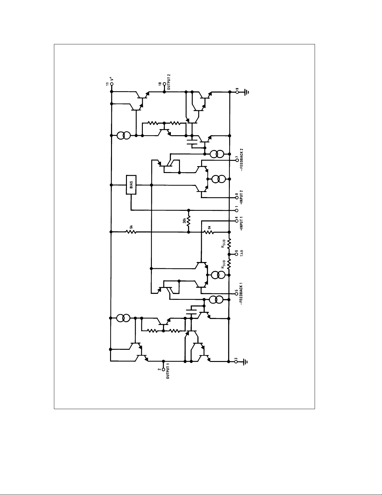
Equivalent Schematic Diagram
TL/H/7933– 2
3
 Loading...