

Page 1
Your excellent helper in cable test!
MOD EL:NF -HDMI -II
INSTRUCTION MANUAL INSTRUCTION MANUAL INSTRUCTION MANUAL INSTRUCTION MANUAL
HDMI Cable Tester
OR
O
IG
RIGI N
I
NA
L
AL
A
UT
AUTH ENTI
H
ENTI C
C
e
d
t
n
p
e
t
r
a
o
d
P
u
c
t
s
,
t
ng
i
i
e
f
r
e
n
t
o
n
t
u
a
o
l
l
C
o
w
e
d
RE V1 .0
Page 2
DESCRIPTION
The Noyafa NF-HDMI-II HDMI Cable Tester is designed for
professional HDMI installations. This portable device allows
installers to quickly test, troubleshoot, and verify HDMI (high
definition multimedia interface) cables.NF-H DMI is designed
to test wire circuit state of HDMI cables with Type A & C
connectors conforming to 1.0, 1.1, 1.2, 1.2a, 1.3, 1.3a, 1.3b,
1.3c, 1.4, 1.4a Category 1 and Category 2 cables.
Equipped with 3 test modes, Automatically fast/slow scan
or manual test for step by step, this tool can either test the
conductors in straight、short、open、crossover in all RGB
conductors.
SAFETY INFORMATION
Safety is essential in the use and maintenance of
NOYAFA equipment. This instruction manual and any
markings on the tool provide information for avoiding
hazards and unsafe practices related to the use of
this tool. Observe all of the safety information provided.
Warnings
●
Do not connect tester to a live circuit as it may
damage the unit.
It is easy to damage this tester with charged HDMI lines.
●
Caution
●
Read all instructions in this manual before using this
tester. Failure to do so may result in damage to the tester
or injury to the user.
●
Do not drop or get the unit wet. Do not expose tester to
extreme humidity or direct sunlight.
01
Your excellent helper in cable test!
Page 3

●
Do not use this tester with its case open, or with parts
removed. Doing so may damage the tester and/or injure
the user.
●
Repairs and maintenance must only be carried out by
qualified service personnel or qualified electricians/
technicians who know the dangers.
Follow the recommendations of any Trade
●
Organizations or Regulatory Agencies whose scope
encompasses the use of this tester or injury to the user.
Remove the battery when the tester not in use for
●
longer than a month. Chemical leakage from the battery
could damage the tester.
Please use batteries according to the specification;
●
otherwise it may result in damage to equipment.
CONTENTS
Your NF-HDMI-II HDMI Cable Tester contains the following
1. 1 x Master unit.
2. 1 x Remote unit.
3. 1 x Pouch bag.
4. Users' Manual.
FEATURES:
The NF-HDMI-II HDMI cable tester allows the fast and
accurate verification both HDMI type A and Type C
cables, mapping continuity and proper configuration
and displays 19 pins and shield connection status on
both main and remote unit.
Your excellent helper in cable test!
02
Page 4

For HDMI cables Type A, C
Test all HDMI cables with Type A to A, A to C and C to C
connectors, especially for fragile, easily damaged HDMI
patch cord and in-wall HDMI cables.
Loopback function
Design with loopback function allows test HDMI type
A to A, A to C on main unit.
3 Test Modes
●
Fast continuity scans for testing all conductors'
status in a cable.
●
Slow continuity scans for testing all conductors'
status in a cable.
●
Manual test for step by step scan detecting of
individual conductors' situation.
HDMI Cable Mapping
Automatically detect wiring on HDMI type A or type C
condition in straight、short、open、crossover in pin
#1~#19 and Shield conductor.
Troubleshooting
Quickly troubleshoot and verify HDTV installation
and DIY termination in the field.
03
Your excellent helper in cable test!
Page 5

SPECIFICATIONS:
●
Cables Tested:HDMI cables with Type A & C
connectors conforming to 1.0, 1.1, 1.2, 1.2a, 1.3, 1.3a,
1.3b, 1.3c, 1.4, 1.4a Category 1 and Category 2 cables.
●
Support test (main unit and remote unit):
19 pin-to-pin wire map and shielding detection.
●
Test interface of Master unit:
HDMI (type A) ×1 pcs, Mini HDMI (type C) ×1 pcs.
●
Test interface of Remote unit:
HDMI (type A) ×1pcs, Mini HDMI (type C) ×1 pcs.
●
Cable length:Under 50 meters.
●
Test Mode:
Automatically fast scan、Automatically Slow scan.
●
Displays:
19 LEDs and shield LED on both main and remote unit.
●
Beeper indication.
●
Low battery indication:Under 6.0V
●
Power source:
DC 9V(NEAD 1604/6F22)×1 (not included)
●
Dimension:
Main unit:103×66×27,Remote unit:103×35×27 mm
●
Weight:130g (not incuding battery)
●
Operating environment:
32ºF to 104ºF (0ºC to 40ºC)<80% RH
●
Storage environment:
14ºF to 122ºF (-10ºC to +50ºC)<70% RH
Your excellent helper in cable test!
04
Page 6
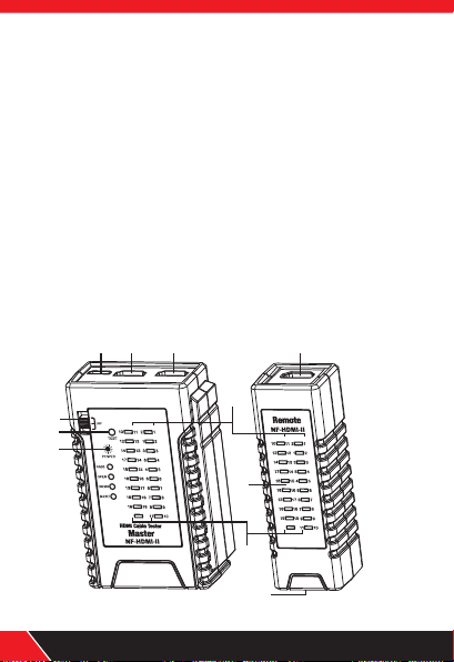
PRO DU CT D IAGRAM(Fi g 1)
1.LO OP BACK:Mi ni -HDMI ( C Type )
Thi s so cket no t on ly can be u sed on Ma st er unit
loo pb ack tes t bu t also ca n be used o n Ma ster un it
Min i- HDMI (C Type) w it h Remot e un it Mini -HDMI
(C Type) to p er form sc an t est.
2.MA IN:H DMI (A Type)
3.LO OP BACK:HD MI ( A Type)
4.Re mo te unit:H DM I (A Type)
5.Re mo te unit:M in i-HDM I (C Typ e)
6.Sw it ch:MAST ER /OFF/ REMOT E
7.TE ST:A utoma ti c fas t/ slow sc an o r manua l te st for
ste p by s tep.
8.Po we r and low b at tery in dicat io n.
9.HD MI ( A Type) P in numb er.
10.M in i-HDM I (C Typ e) P in numb er.
11.LED for i nd icati ng s ignal s it uatio n.
2
1 4
3
MASTER
6
C p
i
n
A p
in
A pi
C pin
n
REMOTE
7
8
Clock S
Dat
a 2
+
C
l
oc
k -
Da
t
a 2S
C
E
C
Dat
a 2
-
U
t
i.
/
Res
.
Dat
a 1
+
SC
L
D
a
t
a 1S
SD
A
Da
t
a 1
-
DDC
/
C
E
C
Da
t
a 0
+
+5
V P
o
w
er
D
at
a 0S
Ho
t P
l
ug
Da
t
a 0
-
S
S
Sh
i
el
d
Clo
ck +
9
C p
in
A p
A p
in
in
C p
in
Clo
ck S
D
a
ta 2
+
Cl
ock -
Dat
a 2
S
C
E
C
Dat
a 2
-
Ut
i.
/
Res
.
D
a
t
a 1
+
S
C
L
D
ata 1
11
S
S
D
A
D
ata 1
-
D
D
C
/C
EC
D
ata 0
+
+5
V P
o
wer
Da
t
a 0
S
H
o
t Pl
ug
Dat
a 0
-
S
S
S
hi
eld
Clo
ck +
10
Mast er U ni t Remo te U ni t
05
5
Fig 1
Your excellent helper in cable test!
Page 7

HDMI Cable Wire / Pin And Signal Description:
HDMI
(A)Pin #
1
2
3
4
5
6
7
8
9
10
11
12
13
14
15
16
17
18
19
S
MINI-HDMI
(C) #Pin
11
10
12
14
17
15
16
13
18
19
S
2
1
3
5
4
6
8
7
9
Pin
Assignment
Data 2+
Data 2S
TMD S Re d Da ta S hi el d
Data 2-
TMD S Re d Da ta M in us
Data 1+
TMD S Gr ee n Da ta P lu s
Data 1S
TMDS Green Data Shield
Data 1-
TMDS Green Data Minus
Data 0+
TMD S Bl ue D at a Sh ie ld
Data 0S
TMD S Bl ue D at a Mi nu s
Data 0-
Clock +
Clock S
Clock -
Consu me r El ec troni cs
CEC
Reser ve d
DDC/C EC
+5V Pow er
Hot Plu g
Contr ol
SCL
SDA
Data shield for the display
data channel and consumer electronics control
Shied
Signal Description
TMD S Re d Da ta P lu s
TMD S Bl ue D at a Pl us
TMD S Cl oc k Pl us
TMD S Cl oc k Sh ie ld
TMD S Cl oc k Mi nu s
Uti li ty /R es erved
Seria l Cl oc k
Seria l Da ta
+5V Pow er
Hot Plu g De te ct
Shied
Your excellent helper in cable test!
06
Page 8

Correspo nding to the Pins Defin ition of the
HDMI cable s(Fig 2)
151719
1618
135791113
2468101214
OPER ATION
Note
●
When all LEDs are lighted all LEDs will decrease
brightness.
●
Master unit shorted pins LED will be brighter than
others when shorted 2 pins above that is correct.
●
Shield LED will light up after #1~19 LEDs light up in
sequence on any testing mode. If the HDMI cable has
a shield, the Shield LED will light up, if without shield
the LED will be unlighted.Power off:
Powe r of f:
Slide upper left switch to “OFF”,”P OW ER ” LE D
will go out and the unit will no longer work when
pushing the “TEST” button.
07
Your excellent helper in cable test!
Page 9

Mast er unit l oop c ontin uity sc an
test ing fun cti on
Note
When performing master unit scan test, sequence of
LEDs light up as below.LED#1 (Data 2﹢)→ LED#10
(Clock ﹢)→ LED#S (Shield)→ LED#11 (Clock S ).
※ Insert one of A type connector of cable to Master
unit LOOPBACK (A Type) socket and insert the other
one to Master unit MAIN (A Type) socket for test HDMI
cable A type to A type.
※ Insert A type connector of cable to Master unit
LOOPBACK (A Type) socket and insert C type
connector of cable to Master unit Mini-HDMI (C Type)
for test HDMI cable A type to Mini-HDMI (C Type).
1.Slide upper left switch to “MASTER” then “POWER”
LED lights up, Master unit #1~19 and “Shield” LEDs will
all light up with a long beep sound then all LEDs are off
except “POWER”LED for saving power and the unit is
ready for testing.
2.Push “TEST” button to perform master unit continuity
scan test, it will continually scan 1~19 pin and shield
conductor, Master unit #1~19 and Shield LEDs will light
up in sequence fast, finally master unit LED will indicate
testing result with sound as below. The testing result
will keep 5 second then all LEDs are off except
“POWER” LED for saving power. Press “TEST”
button again for test.
Your excellent helper in cable test!
08
Page 10

3. Master unit scan test result with beep sound as below.
Straight: With a long “beep” sound: Meaning
●
1~19pi n and S pin all straight connected. (Fig 3.)
Open: with a short “beep” sound。No connected
●
pins LED are off. Example: Test HDMI (A Type) to
HDMI (A Type) cable that pin #2, #5, #8 and #11 are
not connect ed , or test HDMI (A Type) to Mini-HDMI
(C Type) cable that pin #1、#4、#7、#10 are not
connected. (Fig 4.)
Short: With three short “beep” sound. Shorte d pins
●
LED will light up at same time. Example: Test HDMI
(A Type) to HDMI (A Type) cable that pin #4、#5、#6
are shorted or test HDMI (A Type) to Mini-HDMI
(C Type) cable that pin #4、#5、#6 are shorted. (Fig 5.)
Crossover: With two short “beep” sound. Crossed
●
pins LED will light on at same time. Example: Test HDMI
(A Type) to HDMI (A Type) cable that pin #13 crossed
with pin #17 and pin #14 crossed with pin #19, or test
HDMI A Type) to Mini-HDM I (C Type) cable that pin
#14 crossed with pin #13 and pin #17 crossed with
pin #19. (Fig 6.)
09
Your excellent helper in cable test!
Page 11

MASTER
REMOTE
C pin A pin C p in
Clock S
Clock -
CEC
Uti./ Res.
SCL
SDA
DDC/C EC
+5V Pow er
Hot Plu g
S S
Shiel d
Data 2+
Data 2S
Data 2-
Data 1+
Data 1S
Data 1-
Data 0+
Data 0S
Data 0-
Clock +
A pin
MASTER
REMOTE
C pin A pin C p in
Clock S
Clock -
CEC
Uti./ Res.
SCL
SDA
DDC/C EC
+5V Pow er
Hot Plu g
S S
Shiel d
Data 2+
Data 2S
Data 2-
Data 1+
Data 1S
Data 1-
Data 0+
Data 0S
Data 0-
Clock +
A pin
Fig 3 . St ra ig ht
MASTER
C pin A pin C p in
REMOTE
Clock S
Clock -
CEC
Uti./ Res.
SCL
SDA
DDC/C EC
+5V Pow er
Hot Plu g
S S
Shiel d
Fig 5 . Sh or t
Your excellent helper in cable test!
Data 2+
Data 2S
Data 2-
Data 1+
Data 1S
Data 1-
Data 0+
Data 0S
Data 0-
Clock +
Fig 4 . Op en
A pin
MASTER
REMOTE
C pin A pin C p in
Clock S
Clock -
CEC
Uti./ Res.
SCL
SDA
DDC/C EC
+5V Pow er
Hot Plu g
S S
Shiel d
Data 2+
Data 2S
Data 2-
Data 1+
Data 1S
Data 1-
Data 0+
Data 0S
Data 0-
Clock +
A pin
Fig 6 . Cr os so ve r
10
Page 12

Master unit with Remote unit automatic
testing function
Insert one of A type connector of cable to Master unit
※
MAIN (A Type) socket and insert the other one to Remote
unit A Type connector for test HDMI cable A type to A type.
※ Insert A type connector to Master unit LOOPBACK
(A Type) and insert C type connector to Remote unit
Mini-HDMI (C Type) for test HDMI cable A type to
Mini-HDMI (C Type).
※ Insert one of C type connectors of cable to Master
unit Mini-HDMI (C Type) socket and insert the other one
to Remote unite (C Type) socket for test HDMI cable
Mini-HDMI (C Type) to Mini-HDMI (C Type) socket.
1.Slide upper left switch to “REMOTE” then “POWER”
LED lights up. Master unit #1~19 and “Shield” LEDs will
all light up with a long beep sound then Master unit and
Remote unit both #1~19 and “Shield” LEDs will indicate
tested result. Testing result will keep 12 seconds then all
of LED are off except “POWER”LED for saving power.
2.Press “ TEST” button then Master unit and Remote unit
both #1~19 and “Shield” LEDs will indicate tested result.
Testing result will keep 12 seconds then all LEDs are off
except “POWER”LED for saving power.
1.LED indicates test result as below:
Straight Master unit and Remote unit both testing pin
● :
#1~19 and “Shield” LEDs are all lighted up. (Fig 7.)
11
Your excellent helper in cable test!
Page 13

Open: Master unit and Remote unit both no connected
●
pins LEDs are off. (Fig 8.)
Short: Master unit testing short pin LEDs brighter
●
than others. Remote unit shorted pins LEDs are off.
(Fig 9.)
Crossover: It can't be tested on this mode.
●
Master unit with Remote unit slow continuity
scan testing function:
1.Press “ TEST button during LED indicate automatic
testing result or Press twice “ TEST” b utton before LED
off for p erfo rm aut omat ic tes ting , it wil l continually scan
#1~#19 pin and shield conductor. Master unit and
Remote unit both #1~19 and Shield LEDs will light up in
sequence very slow and sustained repeated automatic
scan.
”
2.LED indicate testing result as below:
Straight●
: Master unit and Remote unit both testing
pins # 1~19 an d Shie ld LED s are all l ight ed up in sequen ce.
(Fig 7. )
●
Open: Master unit and Remote unit both LEDs are
off whe n scan t o no con nect ed pin s, oth ers LE Ds are
all lighted up in sequence. Example : Test HDMI
(A Type) to HDM I (A Type) cable that pin #2、#5、#8、
#11 are not c onne cted , or tes t HDMI ( A Type) to
Mini-HDMI (C Type) ca ble th at pin # 1、#4、#7、#1 0
are not connected, or test Mini-HDMI (C Type) t o
Mini-HDMI (C Type) ca ble th at pin # 1、#4、#7、#1 0
are not connected. (Fig 8.)
Your excellent helper in cable test!
12
Page 14

● Short: Master unit LED brighter than others and
Remote unit LED off w hen sc an to sh orte d pins ,
Master unit and Remote unit both LED are all lighted
up in sequence, Example : Test HDMI (A Type) to
HDMI (A Type) cable t hat pi n #4、#5、#6 a re sho rted ,
or teat HDMI (A Type) to Mini -HDM I (C Type) ca ble
that pin #4、#5、#6 are shorted, or tes t Mini -HDM I
(C Type) to M ini- HDMI ( C Type) cab le tha t pin #4、# 5
、#6 are shorted. (Fig 9.)
Crossover: Master unit LEDs light up in sequence
and Remote unit LEDs light up sequence by crossed
pins, Example : test HDMI (A Type) to HDM I (A Type)
cable that pin #13 with pin#17 are crossed and pin
#14 with pin #19 are crossed, or test HDMI (A Type)
to Mini-HDMI (C Type) c able p in #14 w ith pi n #13 an d
pin #17 with pin #19 are crossed, or test Mini-HDMI
(C Type) to M ini- HDMI ( C Type) cab le pin # 14 wit h
pin #13 are crossed and pin #17 crossed with #19 are
crossed. (Fig 10.)
13
Your excellent helper in cable test!
Page 15

MASTER
REMOTE
C pin A pin C p in
Clock S
Clock -
CEC
Uti./ Res.
SCL
SDA
DDC/C EC
+5V Pow er
Hot Plu g
S S
Shiel d
A pin
Data 2+
Data 2S
Data 2-
Data 1+
Data 1S
Data 1-
Data 0+
Data 0S
Data 0-
Clock +
Fig 7 . St ra ig ht
C pin A pin
Clock S
Clock -
CEC
Uti./ Res.
SCL
SDA
DDC/C EC
+5V Pow er
Hot Plu g
S
Shiel d
A pin
C pin
Data 2+
Data 2S
Data 2-
Data 1+
Data 1S
Data 1-
Data 0+
Data 0S
Data 0-
S
Clock +
MASTER
C pin A pin C p in
REMOTE
Clock S
Clock -
CEC
Uti./ Res.
SCL
SDA
DDC/C EC
+5V Pow er
Hot Plu g
S S
Shiel d
Your excellent helper in cable test!
Data 2+
Data 2S
Data 2-
Data 1+
Data 1S
Data 1-
Data 0+
Data 0S
Data 0-
Clock +
A pin
C pin A pin
Fig 8 . Op en
Clock S
Clock -
CEC
Uti./ Res.
SCL
SDA
DDC/C EC
+5V Pow er
Hot Plu g
S
Shiel d
A pin
C pin
Data 2+
Data 2S
Data 2-
Data 1+
Data 1S
Data 1-
Data 0+
Data 0S
Data 0-
S
Clock +
14
Page 16

MASTER
REMOTE
C pin A pin C p in
Clock S
Clock -
CEC
Uti./ Res.
SCL
SDA
DDC/C EC
+5V Pow er
Hot Plu g
S S
Shiel d
A pin
Data 2+
Data 2S
Data 2-
Data 1+
Data 1S
Data 1-
Data 0+
Data 0S
Data 0-
Clock +
Fig 9 . Sh or t
C pin A pin
Clock S
Clock -
CEC
Uti./ Res.
SCL
SDA
DDC/C EC
+5V Pow er
Hot Plu g
S
Shiel d
A pin
C pin
Data 2+
Data 2S
Data 2-
Data 1+
Data 1S
Data 1-
Data 0+
Data 0S
Data 0-
S
Clock +
MASTER
REMOTE
C pin A pin C p in
Clock S
Clock -
CEC
Uti./ Res.
SCL
SDA
DDC/C EC
+5V Pow er
Hot Plu g
S S
Shiel d
Data 2+
Data 2S
Data 2-
Data 1+
Data 1S
Data 1-
Data 0+
Data 0S
Data 0-
Clock +
A pin
A pin
C pin A pin
C pin
Data 2+
Clock S
Data 2S
Clock -
Data 2-
CEC
Data 1+
Uti./ Res.
Data 1S
SCL
Data 1-
SDA
Data 0+
DDC/C EC
+5V Pow er
Data 0S
Hot Plu g
Data 0-
S
S
Shiel d
Clock +
Fig 10 . C ro ss ov er
15
Your excellent helper in cable test!
Page 17

Master unit with Remote unit fast continuity
scan testing function:
1.Press “ TEST” button during the slow continuity scan
testing, or press three times“ TEST” button after the
automatic testing LEDs are off:It will fast scan pin
1~19pin and Shield,Master unit and Remote unit both
#1~19 and Shield LEDs will light up in sequence fast and
sustained repeated automatic scan.
2.The test result please refer to the slow continuity scan
testing function. (Fig 7. ~ Fig 10.)
Master unit with Remote unit manual scan
testing function:
1.Press “ TEST” button for three seconds until pin #1
LED lights up, pin #2 ~ 19pin+Shield LEDs light up
step by step sequentially after pressing “ TEST” button
and sustained repeating.
2.The test result please refer to the slow continuity
scan testing function. (Fig 7. ~ Fig 10.)
3.Press “ TEST” button three seconds again then go
back to automatic testing mode.
Your excellent helper in cable test!
16
Page 18

BATTERY LI FE AND R EPL ACEME NT:
Cau tion
● To avoi d unr eliab le te st resu lts , rep lace th e bat tery
as so on as t he low ba tte ry indi cat ion app ear s.
War ni ng s
● To avo id p os si bl e el ec tr ic s ho ck o r pe rs on al i nj ur y,
turn off th e ma st er u ni t an d di sc on ne ct a ll t es t le ad s
before replacing the battery.
Batt er y St at us :When ”PO WE R/ LO W BAT T.”
LED is f la sh in g on t he master u ni t, i t me ans
the ba tt er y vo lt age is unde r 6. 0V w hi ch couldn 't
powe r th e de vi ce o n. Please r ep la ce t he batter y
as the f ol lo wi ng s tep:
1.Tu rn o ff t he m as te r unit and di sc on ne ct all test
lead s be fo re r ep lacing th e ba tt er y.
2.Pro pe rl y re pl ace the bat te ry i nt o the
batt er y ca se .
3.Use o nl y a DC 9 V( NE AD 1604/6 F2 2) b at tery.
HDMI ® is a r eg is te red trade ma rk o f HD MI
Lice ns in g, L LC .
17
Your excellent helper in cable test!
Page 19

NF- 306 NF- 868 N F- 82 08
NF- 268 NF- 806R
NF- 468L NF -3 468 NF8 108-M
NF- 388 NF- 903 NF- 906A
Your excellent helper in cable test!
NF- 816
18
Page 20

Your excellent helper in cable test!
SHENZHEN NOYAFA ELECTRONIC CO.,LTD
 Loading...