

Page 1
MODEL:NF-906
Your excellent helper in cable test!
INSTRUCTION MANUAL INSTRUCTION MANUAL INSTRUCTION MANUAL INSTRUCTION MANUAL
Optical Power Meter
n
u
o
C
ORI GINAL
ORI GINAL
AUT HENTI C
AUT HENTI C
d pr
e
t
n
e
t
a
P
ng
i
t
i
e
f
r
e
t
o
d
u
c
t
s
,
n
o
t
a
l
l
o
w
e
d
RE V1. 0
Page 2

Contents
1. Brief introduction ----------------------------------------------- 1
1.1 Summarize ------------------------------------------------------- 1
1.2 Product features ------------------------------------------------ 2
1.3 Technical parameters ------------------------------------------ 2
1.4 Main applications ----------------------------------------------- 3
2. Functional description ---------------------------------------- 3
2.1 Startup and shutdown ------------------------------------------ 3
2.2 Auto-off activation and shutdown ---------------------------- 3
2.3 Backlight activation and shutdown -------------------------- 3
2.4 Description for control panel ---------------------------------- 4
3. Handling instruction for NF-906 Fiber power meter --- 5
3.1 Description for the information on LCD -------------------- 5
3.2 Test wavelength selection ------------------------------------ 6
3.3 Absolute power measurement ------------------------------- 7
3.4 Relative power (LOSS) measurement --------------------- 7
4. Maintenance ---------------------------------------------------- 10
4.1 Probe cleanness -------------------------------------------- 10
4.2 9V battery replacement ------------------------------------ 11
4.3 Calibration and measurement ------------------------------ 11
4.4 Transportation ------------------------------------------------- 11
5. Common faults and removal methods ----------------- 12
6. Defects liability period -------------------------------------- 12
6.1 General information ------------------------------------------ 12
6.2 Certificate of qualification ----------------------------------- 13
7. Standard configuration -------------------------------------- 13
Your excellent helper in cable test!
Page 3
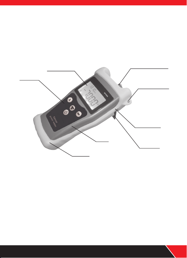
1. Brief introduction
All the details including operation procedure & technical parameters
and as well as others related can be found in this operation manual
for NF-906A and NF-906C series products as shown in the following
photo .
LCD screen
Key field
Body
Sheath
Optical interface
Hanging hole
DC socket
Support
1.1 Summarize
NF-906 portable optical power meter has been equipped with
∮1.0mm large-area detector so that the stability and reliability can
be enhanced effectively; it is a kind of portable tester used for the
installation, debugging and maintenance of fiber network specially.
It has been widely used in various fields, such as cable construction
and maintenance, optical fiber transmission, optical fiber
communication, fiber optical sensor, CATV, etc.
Your excellent helper in cable test!
01
Page 4
1.2 Product features:
● New REF user-defined.
●
User self-calibration function.
●
9V laminated battery with 200hrs battery life.
●
With FC/SC/ST general-purpose interfaces
●
Optional auto-off function and backlight switch.
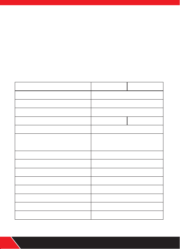
1.3 Technical parameters
Mode l
Wav e- length(nm)
Prob e
Dete ct io n limit
Powe r de te cting range(d Bm)
Unce rt ai nty degree
Stan da rd w avelength(n m)
Disp la y re solution
Working te mp( ℃ )
Stor ag e te mp(℃)
Auto ma ti c shutdown ti me(m in)
batt er y se rving time(h)
Over al l di mension(mm)
Powe r su pp ly
Weight(g )
02
NF-9 06 A
NF-9 06 C
800~ 17 00
InGa As
∮1.0m m
-70~ +1 0
-50~ +2 6
±5%
850、13 00、1 31 0、1490、
1550、1 62 5
0.01 dB m
-20~ +7 0
-30~ +8 0
15
200
185×10 5×50
9V bat te ry, AC ada pt er
350
Your excellent helper in cable test!
Page 5

1.4 Applications
◆Measuring power output.
◆Measuring loss in fiber cable or device.
◆Measuring loss in a fiber device.
◆Identifying system problems.
2. Functional description
2.1 Startup and shutdown
Press button to turn the tester on.
Press for approximately 2 seconds to turn it off.
2s continuously, the meter will be closed.
2.2 Auto-off function
The Auto-off function is auto-matically enabled when NF-906 is
turned on. the unit will turn off after 15mins.Auto-off is displayed
when the feature is on. The Auto-off function can be toggled on
or off by press the power button.
2.3 Backlight
The backlight is on when the tester is turned on and when any key
is pressed.The backlight times out after approximately 30 seconds
of inactivity to conserve battery cover.
Your excellent helper in cable test!
03
Page 6

2.4 Description for control panel
λ
dBm
W
Optical
REF
powe r meter
(1)Power Key
Used to turn on the power meter, if press it by 2s continuously,
the meter will be turned off.
Auto-off function selection: this key can be used to activate or
shut down the Auto-off function, in addition, if there is no operation
over 15min, the power meter will be off automatically.
(2)Wavelength Key
This key is used to select the desire wavelength value at the range
of: 850nm,1300nm,1310nm,1490nm,1150nm and 1625nm, once
confirmed, the specified value will be on the left upper corner of
screen.
(3)Power conversion key
This button can be used for the conversion between the absolute
and relative measurements of optical power.
λ
dBm
W
04
Your excellent helper in cable test!
Page 7

(4) Calibration Key
Press this key continuously to save the current power value as
reference value, which will be on the right upper corner of screen;
if just press this key shortly, it will be switched to relative power
measurement, while the reference power value will be shown on
the right upper corner of screen, and show the relative power value
between the current measurement and reference power, the unit is dB.
REF
3. Handling instruction
3.1 Information on LCD
After press key to start the meter, the following information
will be shown on LCD:
(1)if the meter is supplied by battery, the icon at the left bottom
will be ON. With the reduce of electric amount of battery, the
display segment of battery becomes less and less till empty.
(2)When connect with AC adapter, a icon will be lightened at
the middle of screen, at the same time, the electric amount icon
is ON as well.
(3)At the left lower position, it is a icon.The Auto-off
function is activated simultaneously and the icon is lightened as
well, but if there is no operation, the meter will be shut down
15mins later.
“Auto-off”
Your excellent helper in cable test!
05
Page 8

(4)At the middle display-area of screen, the value of power will be
displayed, the unit is dBm,W,dB.
(5)At right upper display-area of screen, show reference power
value, and the wavelength value at the left.
(6)The user self-calibration function is just the course of power
conversion and calibration.( calibration of each wavelength)
A. After open the battery cover. Turn the toggle switch to “ON”
position, then it is available to carry out power calibration after
startup.
B. The details of calibration are shown as follows:
REF Key
dBm/W Key
Wav el ength Key
ON/OFF Key
If press it eve ry time, a 0.05 dB value will b e increased for from
current val ue. The p ower value calibra ted will be sho wn on LCD
If press it eac h time, a 0.05d B value will be r educed from curren t
value . The power valu e calibrated will be s hown on LCD
Used fo r th e se lecti on o f wavel en gt h
Short ly p re ss this k ey t o save th e va lu e calib ra te d
Press t hi s ke y by 2s con ti nuous ly t o cl ose the p ow er m eter
C. Open the battery cover, turn the toggle switch to OFF
position for normal operation.
ATTENTION: it is strongly suggested that the fiber power
meter should be measured or calibrated so that the accuracy
and reliability can be guaranteed.
3.2 Wavelength selection
There is a wide range of wavelength including 850nm, 1300nm,
1310nm, 1490nm, 1550nm and 1625 nm for your option, it is
available to carry out switch through the press of key.
λ
06
Your excellent helper in cable test!
Page 9

3.3 Absolute power measurement
(1). Use one major bridle wire to connect the output port of light
source and the detecting port of fiber power meter as shown in
the following fig:
NF-906 Fiber Power Meter
(2).Turn on the light source to enter working mode and select
wavelength to be tested.
(3).Turn on the fiber power meter and select specified wavelength.
(Selection method: press the key to select the desire
wavelength value)
(4).The current power value on screen is just the absolute power
value of current output of light source as shown in the following
Fig( the current value is -09.73dBm):
λ
Light Source
3.4 Relative power(LOSS)measurement
Relative power measurements are used to determine the power
loss between two points in the system.The power level is first
measured at one point and that value is saved in the meter as a
reference. The power is then measured at another point. The
meter subtracts the reference value from the new reading and
displays the difference in dB
Your excellent helper in cable test!
07
Page 10

(1). Connect the desired connector to the meter, connect the two ends
of optical fiber jumper with light source and power meter.
NF-906 Fiber Power Meter
Light Source
(2). Turn on the light source and power meter to enter working mode
and select wavelength to be tested.
(3). When the output power of light source has been detected, just
REF
press key, this power value will be stored as the current reference
valve (this power value consists of actual output power of light source
and loss value caused by major test bridle wire)
(4). Connect the tested optical fiber jumper with light source and
power meter.
NF-906 Fiber Power Meter
08
Light Source
Your excellent helper in cable test!
Page 11

(5). Shortly press key, the value on screen is the loss value of
REF
the bridle wire being inserted.
(6). If to measure the loss of optical fiber link, it is necessary to
carry out local initialization reference for light source and optical
power meter, as shown in the following Fig, read the initial
reference value on optical fiber meter, and it is available to
press the key continuously to save this reference value.
REF
NF-906 Fiber Power Meter
Light Source
(7). Put the light source and NF-906 Optical Fiber Meter at the two
ends of optical fiber link being tested respectively, the value on
power meter is just the loss value of optical fiber link being tested
(including the loss of linker).
NF-906 Fiber Power Meter
Your excellent helper in cable test!
Light Source
09
Page 12

4.Maintenance
◆Always clean the optical connector each time a connector is
attached.
◆Avoid exposing the unit to temperature extrames. Condensation
can form inside the unit and affect proper operation.
◆Ensure the dust cap is in place any time a connector is not
attached.
◆Store the unit in clean and dry place.
4.1 Probe cleanness
Clean the probe of optical power meter regularly.
1.Open the dustproof cap
2.Screw off the adapter of power meter
3.Use 2.5mm special cotton swab with some anhydrous alcohol
to clean the surface of probe slightly.
WARNING: when clean the probe of optical power meter, it is
forbidden to use any hard thing to touch the surface of probe
in case cause damage to probe; in addition, keep away from a
strong force to avoid crack of probe. Otherwise, the accuracy
of measurement value will be reduced, even it fails to carry
out any measurement.
ATTENTION: when the optical power meter is under idle mode,
cover the dust-cap to keep the optical power meter clean.
10
Your excellent helper in cable test!
Page 13

4.2 9V battery replacement
When install or take out the battery, the following information
may be helpful for your operation:
◆When the battery energy is lower or no 9V battery installed,
a icon will be on screen.
◆Only an eligible 9V battery can be engaged
◆If no use for a long time, take out the 9V battery in case of
corrosion and damage to internal components.
4.3 Calibration and measurement
Under proper conditions, if this meter can be used in a right way,
a better performance can be guaranteed.
In order to guarantee the performance, it is strongly suggested
that a calibration per year should be implemented.
If there is deviation, please calibrate it again.
4.4 Transportation
When under transportation, keep the meter at the specified
temperature range. And it is suggested the operation should
be done as the follows:
◆Only the original packing material can be used
◆Away from high humidity or obvious temperature variation
◆Away from direct sunlight
◆Away from unnecessary impact and vibration.
Your excellent helper !
Your excellent helper in cable test!
11
Page 14

5. Common faults and solutions
Inaccurate
measure result
Unable to start or
no screen display
Dim LCD display
Some variation of
optical power
when initial start
Lower output power
of light source
Poss ib le r eason
Mismatch wavelength
of light source
Inadequate 9V battery
Inadequate battery
No preheating for
optical maser
Unclean connectivit y
port of light source
Solu ti on sComm on f au lts
Check the corrcet wavel ength
is selected
Replace new battery
Use power adapter or
change the battery
Turn on the light source and
activate the operatin g wave
-length, then carry out m easure
-ment after 30min prehe ating
Clean the connectivit y port
completely
6. Warranty
NF-906 is warranted against defects in materials and workmanship
for a period of one year from the date of purchase.
NOTE: if the damage caused by improper operation or wrong
cleanness of optical connector, our company will charge for the
maintenance or replacement.
7.Standard configuration
(1). NF-906 Portable optical power meter----------- 1 piece
(2). Operation Manual----------------------------------- 1 piece
(3). AC Adapter------------------------------------------- 1 piece
(4). 9V battery--------------------------------------------- 1 piece
(5). Cotton swab------------------------------------------ 1 piece
(6). Toolkit------------------------------------------------- 1 piece
12
Your excellent helper in cable test!
Page 15

NF-306 NF-868 NF-820 8
NF-268 NF-806 R
NF-468 L NF -3468 NF8108 -M
NF-388 NF-903 NF-906 A
Your excellent helper in cable test!
NF-816
13
Page 16

Your excellent helper in cable test!
SHENZHEN NOYAFA ELECTRONIC CO.,LTD
 Loading...