

Page 1

Your excellent helper in cable test!
MODEL:NF-8200
Your excellent helper in cable test!
INSTRUCTION MANUAL INSTRUCTION MANUAL INSTRUCTION MANUAL INSTRUCTION MANUAL
LCD Network & Length Tester
SHENZHEN NOYAFA ELECTRONIC CO.,LTD
ORI GINAL
ORI GINAL
AUT HEN TIC
AUT HEN TIC
t
n
e
t
a
P
i
e
f
r
e
t
n
u
o
C
d pr
o
e
d
u
c
t
s
,
ng
n
i
t
o
t
a
l
l
o
w
e
d
RE V1. 0
Page 2
Plea se r ea d and learn saf et y in struction s
befo re u se o r maintain th e eq ui pment
●Ke e p the t est e rs i n r igh t p la c e to av oid h u rt wi th th e s ha r p pro b e.
●Ne v er pu t the e q ui p men t i n th e p lac e wit h m uch d ust , h um i dit y
an d h igh t emp e ra t ure ( o ve r 4 0℃).
●Pl e ase u se ba t te r y acc o rd i ng to t he sp e cif ica t io n ; oth e rw i se, i t
ma y r esu lt in d a ma g e to eq u ip m ent .
●Pl e ase n eve r d is m oun t t he e q uip men t a rbi tra r il y. T he ma int e n
-a n ce an d car e s ha l l be co n du c ted b y pro f ess ion a l pe r son n el .
● Th e t est er wi l l sh u t off a uto m at i cal ly if i t d oe s n ot wo r k fo r
15 m i nut es in s u cc e ssi o n.
●Pl e ase t ake o u t th e b att e ry i n l aun che r a nd re cei v er i f t he
eq u ipm ent i s n ot u s ed fo r a l on g t ime s o as to p r eve nt th a t th e
ba t ter y liq u id i s l eak e d in f u tur e.
●Ne v er us e the e q ui p men t t o de t ect p owe r c ord w ith e l ec t ric i ty
(s u ch as p owe r s up p ly ci r cu i t of 22 0V) , o th e r wis e , it m a y
re s ult i n dam a ge t o e qui p me n t and p ers o nal i nju r y.
●Ne v er co ndu c t re l ate d o pe r ati on of c o mmu nic a ti o n lin e i n
th u nde rst o rm w e ath e r so a s t o pre ven t l ig h tni n g st r oke a n d
im p act o n per s on a l saf e ty.
CONTENTS
Ov ervie w. ......... ......... .... ..... .... ......... .. ...0 1
Ma in funct ions ....... ......... .... ..... .... ..... .. .02
Tec hnic al Param eters.... .... ..... .... ..... .. ...02
Pr oduct in terface and key int rodu ction. .0 4
Pr oduct op eration meth od....... .. ......... ..05
a.C abl e l ine-to- lin e t est ......... .... ..... .... ... .... .05
b.C abl e l ength test ........ ......... .... . ...... .... ....0 9
c.C abl e t racing tes t.. ......... ......... . .. ....1 2
.. ..
.. ......... .
d.C ros stal k test .... .... ......... ......... .... . ...... ...1 5
Le ngth Cal ibra te... .... ......... ......... .... ..... .... .16
Da ta loadi ng....... .... ..... .... ......... ......... .... ...16
Se tup .... .... ..... .... ......... ......... ......... .... ..... ..16
La nguag e:Ch inese or En glish.... ......... .... ..17
Un it ..... .... ..... .... ......... ......... ......... .... ..... ...1 7
Li ght .... .... ..... .... ......... ......... ......... .... ..... ...1 8
Au to off .... ......... ......... .... ..... .... ......... .......18
Au to-of f t ime ........ ......... ......... .... ..... .... ....18
Pa cking li st....... .... ..... .... ......... ......... .... ....1 9
Di agram of se ries pro ducts .. .... ......... .......20
.. ..
.. ..
.. ..
.. .
.. ..
.. ..
.. ..
Your excellent helper in cable test!
Your excellent helper in cable test!
Page 3
Overview
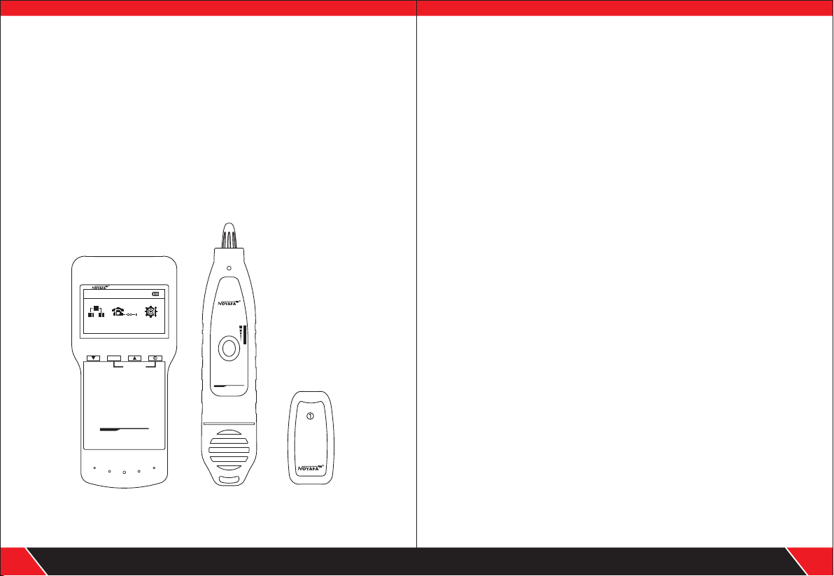
NF-8200 is capable
of av oi di ng current inteferenc e . The equ ip me nt is compos ed
of thr ee par ts: main te st er (NF -8 20 0) , receiver (N F- 82 00 -S ) and
remote iden ti fi er ( NF -8200-R). It h as c ou pl es o f circuit sta te t es ti ng
functions including length tes t, cab le lin e finding, line-to-l in e,
crosstalk an d bre aking poin t, se rv ing as a pr actical tool fo r low
vo ltag e s y ste m i nst a l lat i o n and m a i nte n a nce t echn i c ian s
of co mm un ic ation c ir cu its a nd comprehe ns iv e wirin g circuits. I t is
widely used i n th e fi el ds l ike telepho ne s ys te m, c omputer netwo rk s
and other met al l ea d ci rc uits.
newly develop ed by our compa ny whic h ar e
POWE R
NOYA FA
RJ11
RJ45
PAIR&L
CALIBR ATE
Anti-EI Wire Tracer
LC D Ne two rk
Le ng th Tes te r
EMI TTE R
NF-820 0
Setup
NF-820 0-S
Anti-EI Wire Tracer
PUSH TO TE ST
LCD N et wor k
Len gt h Tes ter
RECE IVER
VOL
NF-82 00-R
WIR EMAP
Main functions
Capable to te st o pe n, s ho rt , cross conn ec ti on , re verse, pairin g
●
connectio n an d br ok en w ire positio ni ng ( R J11,RJ45) .
● To perform cros st al k te st o n network cab le t o so lv e th e potential
problem of sl ow s pe ed .
● To quickly find t he t ar ge t wi re or cable amo ng k in ds o f wi res.
● Measure len gt h of n et wo rk cable, tel ep ho ne c ab le u p to 2500m,
no need of remo te u ni t wh en m easuring le ng th .
● To make a accurat e de te rm in ation of shor t ci rc ui t po sition .
● To trace cable on e xc ha ng er o r Router with ou t cu rr en t
inteferen ce .
● Low voltage p ro mp t fu nc tion is avail ab le (<4 .5 V) .
● Functions o f st or ag e an d memory.
● Automatic d el ay p ow er o n-off a nd b ac kl ig ht function .
● Lanuage& li gh t br ig ht ness can be set i n th e sy st em .
● Single chip s of tw ar e wa tchdog desi gn r un s re li ab ly.
Technical parame ters
(1).
Overall dim en si on s
Main tester : 18 0X 80 X4 0mm; Receiv er : 21 8X 46 X29mm
Remote iden ti fi er : 68 X34X26mm.
(2).
Display
Dot matrix 12 8X 64 ( Effecti ve v is ib le a rea 64X32mm).
(3). Power su pp ly
Main tester : 1. 5V b at te ries of four .
Receiver: 9 V ba tt er y.
(4).Tes ti ng c ab le types
STP/UTP 5E, 6 E ne twork cable , te le ph on e cable, and
common meta l wi re s co nn ected with al li ga to r cl ip.
Your excellent helper in cable test!
01
Main tester
(NF-8200)
Receive r
(NF-820 0- S)
Remote iden ti fi er
(NF-8200- R)
Your excellent helper in cable test!
02
Page 4
(5).Detect in g ca bl e ty pes
STP/UTP 5E, 6 E ne twork cable , te le ph on e ca ble,and com mo n
metal wires c on ne ct ed w ith alligat or c li p.
(6).Operat in g en vi ro nment tempe ra tu re /h umidity
-10 ~ +60 /20% ~ 70%;℃ ℃
(7).Tes ti ng d ev ice interfa ce
Main unit: RJ 45 ( M) , RJ 45 ( S)loop inte rf ac e, R J11main in te rf ac e;
Remote iden ti fi er : RJ 45, connector。RJ11
(8).Length m ea su re me nt
Range: 1-25 00 m;
Calibrati on p re ci si on: 2% (+/-0. 5m , or + /- 1. 5 feet); (calib ra ti on ;
cable >10m) m ea su re me nt precisio n: 3 % (( +/ -0 .5m, or +/-1.5 fe et );
(AMP, CAT5 E, 6E cable mater ia l)
Display uni t: m et er, i nc h, yard.
(9).Length c al ib ra ti on, storage a nd d at a lo ad
User can set a le ng th v al ue a t a known lengt h, s to re t he v alue in
the system, wh ic h ca n be u sed for futur e ch oi ce . an d the calibrati on
length shou ld b e ov er 1 0m .
(10). Line seq ue nc e an d ca ble failure p os it io ni ng
Open, short , re ve rs e , cr oss, crosst al k, e tc .
(11). Languag e se t
Users can cho os e En gl is h or Chinese fo r op er at io n.
(12). Setu p
Unit & brig ht ne ss & Au to -power off ti me c an be set in this m en u.
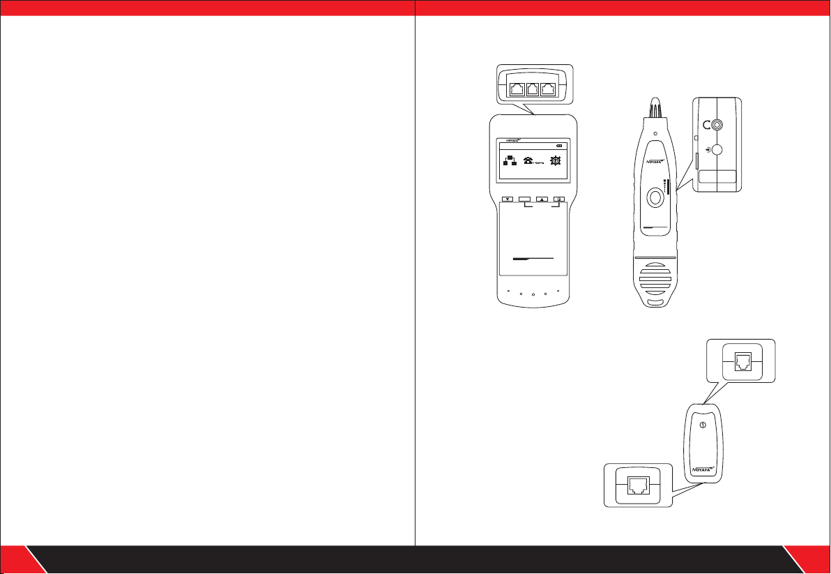
Product interface and key introduction
MAIN RJ11 SCAN
POWER
NF-8200 -S
Anti-EI Wire Tracer
PUSH TO TES T
LCD N etw or k
Len gth T est er
RECEI VER
VOL
NF-820 0-R
RJ11
PAIR&L
CALIBRATE
LC D Net wo rk
Le ngt h Tes te r
EMI TTER
NF-8200
Setup
NOYAFA
RJ45
Anti-EI Wire Tracer
Main test er ( NF -8 200) Receive r (N F- 82 00-S)
Main unit port instructions
(1). Two RJ 45 interfa ces on the main unit:
one of them is “MAIN” interfa ce (“M” for short ),
and the other is “SCAN” inter face (“S” for sho rt);
One RJ11 interf ace.
(2). M interface is used for measu ring leng th and
others, but not for cable tra cing; “S” int erface is
used for cable tracin g test and “local ” connection test ;
(3). RJ11 interf ace is used for line- to-line,
length testin g and line tracin g.
WIR EMAP
Your excellent helper in cable test!
03
Remote iden ti fi er ( NF -8200-R)
Your excellent helper in cable test!
04
Page 5

Product operation method
Bootscreen
Synch ro no us self t es t ( self te st d yn amica ll y displ ay ed i n the lin e
from le ft t o ri ght)
-- - - - -
we lc om e
to c h o ose n o yaf a
NF - 8 200
Test result 1: S ho rt circuit
If there is short circuit wit h the cable and terminal, it will sho w as below:
(Short circui t with 3 and 6)
Sh o r t m a pp i n g:
1 2 3 4 5 6 7 8
5 seconds lat er, t he f ol lo wing main inter fa ce i s di sp layed:
NOYA FA
RJ45 RJ11
Setup
There are three functional options in the main menu interface
. RJ45 — wiremapping / length measurement /
(1)
cable tracing / crosstalk testing
. RJ11 — wiremapping / length measurement /
(2)
cable tracing / crosstalk testing
. Setup— unit / brightness/ auto-power-off time
(3)
Note:
Calibration— Seven calibration coefficient can be stored in it.
User can calibrate network/ Telephone cable.
Data loading---Select the calibration coefficients stored in system.
a.Cable l ine-to-line t est:
Taking network test as an example : after entering RJ45 fun ction to check
wire mapping.At thi s time, the following int erface is shown indic ating tes t
is in process:
NOY AFA
Wi re Map pi ng
Sc a n Ca b le
Ca b le L e ngt h
Your excellent helper in cable test!
05
- - --i d en tif y- - - -
At this time, press any key to return to the main men u, and then press
“ENTER” key for re-te st.
Please do not perform tes t again until short circu it problem solved .
Test result 2: if the far end of the cable to be tested is not plugged in
remote adapter (R) or cable is not plug ged into the local port (S),
the following inter face is shown:
Ca b le open or
to o Sh o rt !
Test result 3:correct connection
the following int erface is shown:
Wir e Map: Rem ote
1 2 3 4 5 6 7 8 G
M:
R:
1 2 3 4 5 6 7 8 G
“M”stands for Master unit. “R” stands for rem ote unit “G” stan ds
for “Grounded”.
Your excellent helper in cable test!
06
Page 6

Test result 4: In case of open circuit existing on far end of the cable,
the following interface is shown:
Wir e Map: Local
1 2 3 4 5 6 7 8 G
M:
S:
1 2 3 X X 6 7 8 G
In the figure, “X” shown in “4” and “5” pin posit ion in “S” line, indicate s there is
open circuit in “4” and “5” pin of the remote pin .
Note: Because net work cable is made of pair cores, if ther e is open circuit,
it will show faults in pairs, just as above "4" &" 5". it means eit her "4" pin
or "5" pin exsits an open circuit , or both "4" and "5" exsit an open circuit.
Test result 5: In case of open circuit existing at the near end of
the cable , the following interface
is shown:
In the figure, “X” shown in “3” and “6” pin posit ion in “M” line, indicate s there is
open circuit in “3” and “6” pin of the near pin.
Test result 6: In case of open circuit existing at the middle part
of the cable , the following
interface is shown:
when testing only with main tester
Wir e Map: Local
1 2 X 4 5 X 7 8
M:
S:
1 2 3 4 5 6 7 8
when testing only with main tester
Wir e Map: Local
1 2 X 4 5 6 7 8
M:
S:
1 2 X 4 5 6 7 8
Test resu lt 7: In case of open circui t existing in the cable when
testing wi th main tester and remote unit together, the following
interface is shown:
In the figu re , “X” sh own in “4” & “5” pin in “M ” & “R” lin e, It has two pos si bl e result s.
Both “4” an d “5” pi n are op en curcu it ed. Or , eith er “4 ” or “5” pi n is open.
Note: Wh en ch ec king wir em ap with mai n tes te r and remot e uni t togeth er,
the cabl e is tes te d in pair. Thus , if there is one pi n is ope n , i t wil l show in pair
as above.
To t est whic h pin is op en , users can ch ec k wirema p onl y wit h main test er li ke
Examp le 4, Ex ample 5 and Ex am ple 6 do.
Test result 8: 6-core telephone cable line sequence test
Before checki ng wiremap of telepho ne cable, users need to choos e "RJ11"
and then check its wirema p. If the testing cable is in good connec tion, it will
displays as follows :
At this time, press any key to return to the main men u, and then press
“ENTER” key for re-test .
Wir e Map: Rem ote
1 2 3 X X 6 7 8
M:
R:
1 2 3 X X 6 7 8
Wir e Map: Rem ote
1 2 3 4 5 6
M:
R:
1 2 3 4 5 6
In the figure, “X” shown in “3” pin posit ion in “M” and “S” line, indicate s there is
open circuit in “3” pin of the middle par t of the cable. Perform"PAIR &LENGTH"
to locate the exact fault point . Refer to the related chapte r below.
Your excellent helper in cable test!
07
Your excellent helper in cable test!
08
Page 7

Special use:
In case of exchanger power-on, the main unit
can test line sequence of the connecting cables
Take network cabl e as an ex ample: one end of the cable is connected with
“MAIN” interf ace of the main unit, and other end is connec ted with exchange r
interface . An d direct connecti on test can be performed. If the exchanger
interface tes ted is reliably conne cted, the followi ng interfaces shown (excha nger
interface is 8-co re):
Short m a p p i n g :
1 2 3 4 5 6 7 8
In case of open circuit with line 1 and 2 of the exchange r tested, the followi ng
interface is show n (exchanger inte rface is 8-core):
Short m a p p i n g :
1 2 3 4 5 6 7 8
b.Cable l ength test:(Test length only w ith the main
tester,don’t connec t cable into remote uni t. )
Firstly insert one end of the testi ng cable into “M” port in the main tester. When
entering ”Cab le Length” testin g function to check the lengt h.At this tim e, the
following int erface is shown:
NOY AFA
Wi re Map pi ng
Sc a n Ca b le
Ca b le L e ngt h
Note: Due to different tec hnical pa rameters with diff erent branded cables,
users are recomme nded to use dynamic calib ration functi on of the equipment
before measur ing length (Refer to the rela ted chapter for more deta ils.) .
- - --i d en tif y- - - -
Test result 1: S ho rt circuit
If there is short circuit wit h the cable and terminal, the fol lowing interface is
shown (Short circ uit with 3 and 6)
Sh o r t m a pp i n g:
1 2 3 4 5 6 7 8
At this time, press any key to return to the main men u, and then press
“ENTER” key to other func tions.
Please do not perform tes t again until short circu it problem solved .
Test result 2: In case of normal pairing and length test,
the following interface is shown:
1 Op en 105. 0m
2 Op en 105. 0m
3 Op en 105. 0m
4 Op en 105. 0m
And then press “UP” or “DOWN” key, the following int erfac e will further
be shown:
5 Op en 105. 0m
6 Op en 105. 0m
7 Op en 105. 0m
9 Op en 105. 0m
Thus , the cable is almost 105m . Only one end of cable conne ct with main
tester, the other end needs no connec tion, so it show "Open" in the pict ure
At this time,pres s “ENTER” to return to the main men u,and then press
“ENTER” key for re-test .
.
Your excellent helper in cable test!
09
Your excellent helper in cable test!
10
Page 8

Test result 4: R J11 (TEL) cable len gth test
If to insert one end of the cable to be tested into “ ” port of the
main tester, the other end is an open circu it, and then select lengt h test, and
then press “ENTER” key to perfo rm length test with the equip ment, the
following int erface will be shown:
And then press “UP” or “DOWN” key, the following interfac e will further be shown:
telephone RJ11
1 Op en 1 0. 1m
2 Op en 1 0 0. m
3 Op en 1 10 . m
4 Op en 1 10 . m
5 Op en 1 0.1 m
6 Op en 1 0 .1 m
c. Cable tracing test:
After powerin g on the main tester and entering
press“ENT ER” key,enterin g main test menu,
to move “ ” cu rsor to cable scan, and then pres s“ENTER” key to find the
line.The foll owing interfa ce will be shown:
Sc ann ing. . .
Connect the cable to be found wit h the correspondi ng RJ45(Scan) por t
emitter
, (RJ11). Take network lin e finding as an example : connect the network
cable to be found with RJ45 port, move “ ” cursor to cable scan , and press
“ENTER” key to perform line fin ding test as shown inth e figure below:
“RJ45” port of the main teste r,
then press “UP”,“ DOWN” key
of the
It indicates that len gth of telephone cabl e is 10.1m
with main tester, the other end needs no conn ection, so it show "Open" in the
pictureAt thi s time,press “ENT ER” to return to th e main menu,and then pres s
“ENTER” key for re-test ..
Your excellent helper in cable test!
11
.
Only one end of cable connect
Your excellent helper in cable test!
12
Page 9

The usage of receiver
Insta ll 9 V ba ttery, p ush the t es t ke y, get c lo se to the c ab les wit h pr ob e.you c an
hear “b ee p” , the pow er l ed flas he s. W hen the p ro be find s th e ta rgete d ca ble,t he
voice w il l be l oudes t, a nd the le d li gh t will be b ri ghtes t.
1.Tracing cable ( RJ45/RJ11 Cabl e) w hich is conne ct ed to
switch o r router.
Insert the cable into por t RJ11/ RJ45 (S), Press the testing key of recei ver, “Power”
will be lighted, then hold the rece iver close to the cables, whe n the probe gets close
to the targeted one, you can hear cle ar and loud “beep,bee p, beep” .
(Note: telephon e cable into RJ11, Lan cabl e into port RJ45(S) )
2. Tracing cable (RJ 11 Ca ble) which is c on nected to
switch o r router.
Insert the cable into por t RJ11, Press the testing key of receive r, “Power” will
be lighted, then hold the rec eiver close to the cables , when the probe gets close
to the targeted one, you can hear cle ar and loud “beep,bee p, beep” .
(Note: turning down the voice slowly help tra ce cable easiler. )
3.Loca te the short or breakge point ( eg : metal line)
Connect the metal lin e with the cable clips, press the tes ting key of receiver,
hold the receiver clo se to the cables, “beep, beep ,beep” will gener ate, but
when the probe target s the breakge point, “bee p,beep,be ep” stops , which
indicates that is where the bre akage is.
Note: 1) the metal line is de-ene rgized.
2) Tur n up the voice, which helps locat e breakge easily.
3) Two cables must be conne cted together, if only one cable, the black
clip has to be grounded.
Your excellent helper in cable test!
13
Your excellent helper in cable test!
14
Page 10

d. Crosstalk test
As shown t he figure below: it shows 3, 6 and 4, 5 with crosst alk. The line
pair with cro sstalk will f lash to indic ate fai lure. In the li ne pair with cr osstalk,
end-to-en d connection is cor rect. How ever the connected lines are from
diffe rent line pairs. Line pair crosstalk will cause an ov er lar ge crosstal k,
otherwise n etwork spee d will be slow.
3
6
4
5
Conne ct ion dia gram of c rosst al k line pa ir
3
6
4
5
Crosstalk interface is shown as below:
Wire Map: Remote
1 2 3 4 5 6 7 8
M:
R:
1 2 3 4 5 6 7 8
Cro ss talk li ne pair f lashe s
Note: In case of t he n on -t wi sted-pair c ab le l ik e te le phone cable ,
due to over lar ge c ro ss ta lk, it genera ll y sh ow n as c rosstalk.
Length Calibrate
The calibrate d cable must be more than 10m, When start ing dynamic calib ratio n,
insert the same type of cables at a specifi ed length into “M” port. It is unnece ssary
to insert into remote unit.
C a l i b r a t i o n ?
No Y es
Select “Yes”, and then press “ENTER” key, the measured lengt h will be shown:
At this time, press “UP” or “DOWN ” key to adjust to show the actual length
as below:
- - B a se Ad j u st - - -
12.5m
When length is given, press “ENTER” key to save the calibration value. The
screen will show calibration 1, cabliration 2...calibration 7. Users can choose
it from “Data load”, which can avoid more calibration next time.
Data loading:
Choose the functions of “Load data”, it will show 7 sets of length values which
were stored before. Select the desired one and then start to test the cable length.
C ali br a t e 1
C ali br a t e 2
C ali br a t e 3
C ali br a t e 4
C ali br a t e 5
C ali br a t e 6
C ali br a t e 7
Re tu r n
Setup
Choose “Setup ” in the main interface,t hen the screen will be as below:
NOYA FA
RJ45 RJ11
Setup
NOY AFA
L a n g : E n g l i s h
U n i t : M e t e r
L i g h t : H i g h
Your excellent helper in cable test!
15
Your excellent helper in cable test!
16
Page 11

Langua ge: Chinese or Englis h
Move“ ” to “ Lang” , then press“ENT ER” key, then the screen
will be as below:
NOY AFA
简 体 中 文
E n g l i s h
Re tu r n
Choose Englis h, return the main interfa ce, then press“EN TER” key,
then the screen will be as below:
NOYA FA
RJ45 RJ11
Setup
Unit :
Set unit : meter
Move to “Unit” item, choos e “meter”,
“ ” then the screen
will be as below:
NOY AFA
U n i t : M e t e r
L i g h t : H i g h
Au t o o f f : O N
Light
Move “ ” to “L igh”, choose the brig htness degree , then the screen
will be as below:
NOY AFA
U n i t : M e t e r
L i g h t : H i g h
Au t o o f f : O N
Auto off
Move“ ” to “ Auto off” , start power-off function to ON,
then the screen will be as below:
NOY AFA
U n i t : M e t e r
L i g h t : H i g h
Au t o o f f : O N
Auto-o ff time
Move “ ” to “A uto-off time”, the n the screen will be as below:
NOY AFA
L i g h t : H i g h
Au t o o f f : O N
Au t o o f f- t i m e
NOY AFA
1 5 m i n
3 0 m i n
6 0 m i n
Note: Setup of the unit of inch and yard is just the same as that of meter.
Your excellent helper in cable test!
17
Choose the time as you need, 15 mins, 30m ins, 60mins,1 20mins.
Your excellent helper in cable test!
18
Page 12

Packing list
1. Emit te r 1PCS
2. Rece iv er 1PCS
3. Remo te a da pter 1P CS
4. Earp ho ne 1PCS
5. RJ11 Ada pt or ca bl e 1P CS
6. RJ45 Ada pt or c able 1PCS
7. Allig at or c lip ada pt or 1PCS
8. User m an ua l 1PCS
9. Kit 1PC S
10. Col or b ox 1P CS
NF-306 NF-838 NF-820 8
NF-268
NF-806 R NF-816
NF-468 L NF-346 8 NF8108-M
Your excellent helper in cable test!
19
NF-388 NF-903 NF-906 A
Your excellent helper in cable test!
20
 Loading...