

Page 1

MODEL:NF-801B
Your excellent helper in cable test!
INSTRUCTION MANUAL INSTRUCTION MANUAL INSTRUCTION MANUAL INSTRUCTION MANUAL
Wire Tracker
n
u
o
C
ORI GINAL
ORI GINAL
AUT HENTI C
AUT HENTI C
d pr
e
t
n
e
t
a
P
ng
i
t
i
e
f
r
e
t
o
d
u
c
t
s
,
n
o
t
a
l
l
o
w
e
d
RE V1 .0
Page 2

Contents
interf a c e s a n d f unctio n s ...............................................1
Parts of e m i t t e r ...................................................................1
Parts of r e c e i v e r .................................................................1
Te l ephone ca b l e t r a c ing funct i o n ..............................2
Te l ephone ca b l e t r a c ing funct i o n ..............................2
Networ k c a b l e t r acing fu n c t i o n...................................3
Networ k c a b l e t r acing fu n c t i o n...................................3
Electr i c w i r e t r acing fu n c t i o n......................................4
Electr i c w i r e t r acing fu n c t i o n......................................4
Networ k c a b l e C o llatio n f u n c t i on ..............................5
Networ k c a b l e C o llatio n f u n c t i on ..............................5
Others f u n c t i o n ................................................................6
Others f u n c t i o n ................................................................6
Open cir c u i t o r s h ort circu i t t e s t ing funct i o n ..............6
Open cir c u i t o r s h ort circu i t t e s t ing funct i o n ..............6
Open cir c u i t o r s h ort circu i t t e s t ing funct i o n ..............6
DC level t e s t i n g f unction ..................................................6
DC level t e s t i n g f unction ..................................................6
DC level t e s t i n g f unction ..................................................6
Access o r i e s.........................................................................7
Specif i c a t i o n of produ c t .............................................8
Specif i c a t i o n of produ c t .............................................8
Specif i c a t i o n of produ c t .............................................8
Diagra m o f s e r i e s produc t s ..........................................9
Diagra m o f s e r i e s produc t s ..........................................9
Diagra m o f s e r i e s produc t s ..........................................9
Your excellent helper in cable test!
Page 3
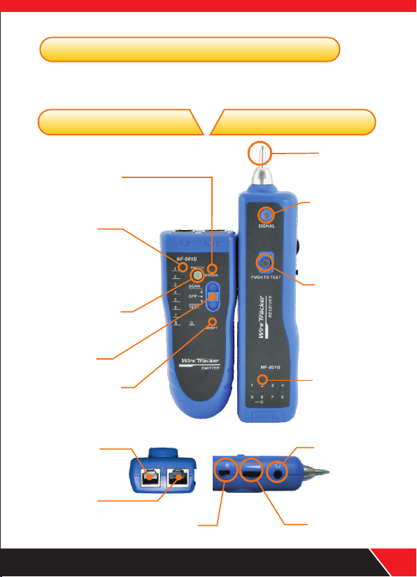
inte rfaces and func tions
Find wire on all types of connected
Find wire on all types of connected operating
Ethernet switch/Router/PC terminal
Ethernet switch/Router/PC terminal
operating
Parts of emitter Parts of receiver
Wire finding
indicator
Signal indicator
Wire sequence
indicator
Function
switchover button
DIP switch
Testing indicator
RJ11 socket
Probe
Inching button
Wire sequence
indicator
Earphone jack
RJ45 socket
Spotlight switch
Your excellent helper in cable test!
Volume
01
Page 4

Teleph one cable tracing function
1. Directly insert telephone wire with RJ11 plug into the RJ11 socket of e mitter;
(Note: Never put energized telephone cable into RJ45 port, in fear of burnout to the tester)
2. Push DIP switch of emitter to position of“SCAN”then wire finding indicator
“STATUS”flashes, which means normal work of emitter;
3. Press the inching button, use the probe of receiver to find target wire at the other end;
4. During testing, function switchover button can be pressed for switchover of dual-tone.
CASE Ⅰ
Find wire on switch
Connect emitter with the
telephone line to be found
Trace cable with receiver at
the other end
02
CASE Ⅱ
Connect emitter with the
Find wire on patch panel
telephone line to be found
Trace cable with receiver at
the other end
Your excellent helper in cable test!
Page 5

Netw ork cable traci ng function
1. Directly insert network cable into the RJ45 port of e mitter;
2. Push DIP switch of emitter to position of “S CAN” then wire finding
indicator “STATUS”flashes which means normal work of emitter;
3. Press the inching button, use the probe of receiver to find target wire at the
other end;
4. During testing, function switchover button can be pressed for switchover of
dual-tone.
CASE Ⅰ
Find wire on router
Connect emitter with the
network cable to be found
CASE Ⅱ
Find wire on net bar
Connect emitter with the
network cable to be found
Your excellent helper in cable test!
Trace cable with receiver at
the other end
Trace cable with receiver at
the other end
03
Page 6

Elec tric wire traci ng function
1. Directly insert RJ11 of crococile clip into RJ11 port of emitter, connect
telephone line with the clamp;
2. Push DIP switch of emitter to position of ”SCAN”then wire finding
indicator “STATUS”flashes which means normal work of emitter;
3. Press the inching button, use the probe of receiver to find target wire at
the other end;
4. During testing, function switchover button can be pressed for switchover
of dual-tone.
Note: The equipme nt is prohibit ed to be used on hea vy-current w ires
04
Connect emitt er with
electric wire t o be found
How to fi nd the wir e from amo ng so many w ires?
It is so sl ow by usin g a multim eter.
No need electric machine to drill !
Your excellent helper in cable test!
Page 7

Netw ork wire Collat ion function
1. Insert the two end s of the network
wire into Rj45 port emitter and receiver.
2. Push function switchover button on
emitter to the position of “TEST ”,
testing indicator “VERIFY” flashes
meaning normal work of emitter.
3. Acc ord ing to 18 in dicat ors, j udge
t he characteristics of short-circuit,
breaking circuit, open circuit and
crossing.
4.During testing, function switchover button can be pressed for switchover
of fast and slow levels.
Note: The equipment is prohibited to
be used on heavy-current wires
Support direct wire collation
of operating switch
Replace the above
tester in cabling
It can take p la ce of
cable tes te r
It can rapidly test open circuit/short
circuit and crossing through the 18
status indicators. which is accurate
and clear.
Your excellent helper in cable test!
05
Page 8

Othe rs function
Open circuit or short circuit testing function Open circuit or short circuit testing function
Push DIP switch on emitter to position of“ TEST” , press function
switchoverbutton on emitter for 2 seconds, “ VERIFY” indicator will
change“ flash” to“ lighting” connect crocodile clamp with RJ11 port,
clamp the two ends of cable with crocodile clamps, in case of short circuit,
indicator “1” of emitter will light up, otherwise it will not. Impendance can
be indicated by brightness of status indicators: the lighter , the smaller the
resistance is; the darker, the bigger.
DC level testing functionDC level testing function
Push DIP switch on emitter to position of“SCAN”, press function
switchover button on emitter for 2 seconds, “ STATUS”indicator will turn
off and“ VERIFY” indicator flashes, insert the crystal plug of crocodile
clamp into RJ11, clamp the two ends of cable with crocodile clamps, in
case that“ STATUS” indicator lights up in red , it means the end
clamped by red clamp i s positiv e pol e, in case th at “ STATUS ”
indicator lights up in green, it means the end clamped by red clamp is
negative pole, electric level can be judged by brightness of the status
indicators; the lighter the indicator, the higher the level is; the darker, the lower.
06
test positive and negative pole of DC electric level
Your excellent helper in cable test!
Page 9

Low voltaage alarm functionLow voltaage alarm function
Push DIP switch on emitter to po sition of“SCAN”, if the that battery level
is lower th an 6.0V,“STATUS”and“VERIFY”indicators w ill light up
at the same time, it indi cates to have new battery.
Earphone functionEarphone function
In noisy environment, earphone can be
used to prevent interference from the outside.
Volume adjusting funcctionVolume adjusting funcction
While tracing cable, volume can be
adjusted for moderate level of sound.
Spotlight functionSpotlight function
You can easily work as usual with backlight at night and in dark.
Energy-savingEnergy-saving
Inching switch can automatically delay power-off.
The continuous lifespan of battery is over 50 hours.
AccessoriesAccessories
RJ11 adapter cable
Your excellent helper in cable test!
Cro codil e clip
RJ45 adapte r cable
Ear phone
9V ba ttery
07
Page 10

Appl icable usersApplicable u sers Appl icable scopeAppl icable scope
Telecom bureau/net bar/telecom
engineering companies / network
engineering companies/power supply/
army and other departments requiring
wire.
Specification of productSpecification of product
Wire engineering of telecom, network
and regular maintenance work; network
line engineering of computer; other wire
engineering and maintenance.
Produ ct na me
Power s upp ly
The max w ork ing cur ren t
Signa l tra nsmis sio n for mat
Signa l out put ele ctr ic st atus
Dista nce o f signa l tra nsm issio n
Appea ran ce dime nsi on
Wei ght
The list of packageThe list of package
Emitter
1.
Receiver
2.
battery
3.
9V
Earphone
4.
adaptor
5.
RJ11
08
Item
1
1
2
1
cable
1
piece
piece
pieces
piece
piece
Speci fic ation
Wire tr ack er
DC, 9V ba tte ry
Emitt er
Recei ver
Multi -fr equen cy im pul se
8Vp-p
≥2km
Emitt er
Recei ver
Whole s et
126×49×34 ,mm
175×42×27 ,mm
270×165×4 5,m m
Emitt er
Recei ver
Whole s et
6.
Cable
RJ45
7.
Instruction manual
8.
9. Toolkit
10.
Color box
crocodile
with
adaptor cable
Your excellent helper in cable test!
≤10mA
≤30mA
0.060 kg
0.072 kg
0.420 kg
clamp 1 piece
piece
1
piece
1
piece
1
piece
1
Page 11

NF-306 NF-868 NF-8208
NF-268 NF-806R
NF-468L NF-3468 NF8108- M
NF-388 NF-903 NF-906A
Your excellent helper in cable test!
NF-816
09
Page 12

Your excellent helper in cable test!
SHENZHEN NOYAFA ELECTRONIC CO.,LTD
 Loading...