

Page 1

NDR-HA4208
NDR-HA4416
U s e r ’s m a n ual
Page 2
NDR-HA4208 / NDR-HA4416 1.2 version - User’s manual
All rights reserved © NOVUS Security Sp. z o.o.
2
EMC (2004/108/EC) and LVD (2006/95/EC ) Directives
CE Marking
Our products are manufactured to comply with requirements of following directives and national
regulations implementing the directives:
• Electromagnetic compatibility EMC 2004/108/EC.
• Low voltage LVD 2006/95/EC with further amendment. The Directive applies to electrical
equipment designed for use with a voltage rating of between 50VAC and 1000VAC as well
as 75VDC and 1500VDC.
WEEE Directive 2002/96/EC
Information on Disposal for Users of Waste Electrical and Electronic Equipment
This appliance is marked according to the European Directive on Waste Electrical and Electronic
Equipment (2002/96/EC) and further amendments. By ensuring this product is disposed of correctly,
you will help to prevent potential negative consequences for the environment and human health, which
could otherwise be caused by inappropriate waste handling of this product.
The symbol on the product, or the documents accompanying the product, indicates that this appliance
may not be treated as household waste. It shall be handed over to the applicable collection point for the
waste electrical and electronic equipment for recycling purpose. For more information about recycling
of this product, please contact your local authorities, your household waste disposal service or the shop
where you purchased the product.
RoHS Directive 2002/95/EC
Concerning for human health protection and friendly environment, we assure that our products falling
under RoHS Directive regulations, regarding the restriction of the use of hazardous substances in
electrical and electronic equipment, were designed and manufactured in compliance with mentioned
regulation. Simultaneously, we claim that our products were tested and do not contain hazardous
substances exceeding limits which could have negative impact on human health or natural
environment.
Information
The device, as a part of professional CCTV system used for surveillance and control, is not designed
for self installation in households by individuals without technical knowledge.
COMMENTS AND WARNINGS
Page 3

NDR-HA4208 / NDR-HA4416 1.2 version - User’s manual
All rights reserved © NOVUS Security Sp. z o.o.
3
SAFETY REQUIREMENTS
ATTENTION!
PRIOR TO UNDERTAKING ANY ACTION THAT IS NOT PROVISIONED FOR THE GIVEN
PRODUCT IN ITS USER’S MANUAL AND OTHER DOCUMENTS DELIVERED WITH THE
PRODUCT, OR THAT ARISES FROM THE NORMAL APPLICATION OF THE PRODUCT, ITS
MANUFACTURER MUST BE CONTACTED OR THE RESPONSIBILITY OF THE
MANUFACTURER FOR THE RESULTS OF SUCH AN ACTION SHELL BE EXCLUDED.
1. The installation of NDR-HA4208, NDR-HA4416 should be made by a qualified service person or a
professional safety system installer.
2. Recorders mustn’t be placed in places where ventilating holes are partially or fully covered.
3. User’s interference inside the device is not allowed and is unnecessary as it does not have any
systems which require adjusting or which are suitable for self-repair. You mustn’t dismantle the
recorder or remove any single fastening screws. If any repairs are necessary contact the service.
The device must be take care of and protected against any mechanical damage.
4. The recorder has to be protected against humidity and dust. In case the recorder had a contact with
water react immediately: switch off the power supply and contact the authorised Novus service. If
the device gets dirty it might get damaged or electrocute someone.
5. The device can only be cleaned with a damp cloth after the power supply has been switched off.
Avoid strong detergents (liquids and sprays). Mild detergents can be used if the recorder becomes
very dirty.
6. Power supply unit cords and signal cords should be laid in a way that eliminates the risk of
mechanical damage; special attention should be paid to the plug. Be careful not to overload sockets
and extension cords so that there is no fire.
7. To avoid recorder’s damage vision and control signals should be equipped with systems protecting
against disturbances, over voltage and atmospheric discharge that are in compliance with Polish
regulations. It is also advised to use ground loop isolators.
8. The device mustn’t be used in conditions which do not fulfil operating requirements as far as power
supply, relative humidity or air temperature are concerned.
9. You cannot allow any metal objects get inside the recorder. It might cause serious damage. If a
metal object gets inside the device contact the authorised Novus service immediately.
10. The manufacturer does not bear responsibility for damage or loss of data stored on HDDs or other
media occurred during the usage of the product.
Page 4

NDR-HA4208 / NDR-HA4416 1.2 version - User’s manual
All rights reserved © NOVUS Security Sp. z o.o.
4
1. FOREWORD INFORMATION ............................................................................................. ..6
1.1 Main Characteristics ........................................................................................................... 6
1.2 Recorder’s technical data ................................................................................................. ...7
2. STARTING THE DEVICE....................................................................................................... 8
2.1 Getting the device ready to work ....................................................................................... 8
2.2 Electrical connection and other back panel elements ....................................................... 9
2.3 Connecting of peripheral equipment ............................................................................... 12
2.4 Front panel description ................................................................................................... 13
2.5 Remote controller ........................................................................................................... 16
2.6 HDD Installation ............................................................................................................ 16
3. RECORDER’S MENU ............................................................................................................ 19
3.1 System Menu .................................................................................................................. 20
3.1.1 Information ............................................................................................................. 20
3.1.1.1 System log ................................................................................................... 21
3.1.1.2 Recording range .......................................................................................... 21
3.1.2 Date /time ............................................................................................................... 22
3.1.3 Disks ....................................................................................................................... 22
3.1.4 Users ....................................................................................................................... 26
3.1.5 System shutdown .................................................................................................... 28
3.1.6 User logout ............................................................................................................ 28
3.2 Network ........................................................................................................................... 29
3.2.1.1 Network ....................................................................................................... 29
3.2.1.2 LAN ............................................................................................................ 30
3.2.1.3 Modem ........................................................................................................ 31
3.2.1.4 DVRNS ....................................................................................................... 31
3.2.2 Notifying ................................................................................................................ 32
3.2.2.1 E-mail .......................................................................................................... 32
3.2.2.2 Call-back connection ................................................................................... 32
3.3 Devices .......................................................................... ........................................... .......33
3.3.1 Cameras .................................................................................................................. 33
3.3.2 Audio ...................................................................................................................... 35
3.3.3 Alarm-out ............................................................................................................... 35
3.3.4 Display ................................................................................................................... 37
3.3.5 Remote control ....................................................................................................... 39
3.4 Recording ......................................................................................................................... 40
3.4.1.Record .................................................................................................................... 40
3.4.2 Schedule ................................................................................................................. 42
3.4.3. Pre-event ............................................................................................................... 43
3.5 Event ................................................................................................................................ 44
3.5.1. Alarm-in ................................................................................................................ 44
3.5.2. Motion detection ................................................................................................... 46
3.5.3. Video loss…………………………………………………………………………47
3.5.4. Video blind ........................................................................................................... 48
3.5.5. System event ......................................................................................................... 48
4. RECORDER’S OPERATION ............................................................................................... 50
4.1 Live monitoring ............................................................................................................... 50
4.2 Active cameo mode ........................................................................................................ 51
4.3 PIP mode ......................................................................................................................... 51
4.4 ZOOM mode ................................................................................................................... 51
4.5 PTZ mode ........................................................................................................................ 51
TABLE OF CONTENT
Page 5

NDR-HA4208 / NDR-HA4416 1.2 version - User’s manual
All rights reserved © NOVUS Security Sp. z o.o.
5
4.6 Image adjustment ............................................................................................................ 52
4.7 Event monitoring ............................................................................................................. 53
4.8 Covert cameras ................................................................................................................ 53
4.9 Spot monitor .................................................................................................................... 53
4.10 Recording video ............................................................................................................. 54
4.11 Recording audio ............................................................................................................. 54
4.12 Playing recorded video .................................................................................................. 54
4.13 Searching video ............................................................................................................. 55
4.13.1 Calendar search ..................................................................................................... 55
4.13.2 Event log search .................................................................................................... 56
4.13.3 Motion search ........................................................................................................ 58
4.13.4 Go to the date/time ................................................................................................. 59
4.15 Record table search ........................................................................................................ 60
4.16 Clip copy ........................................................................................................................ 61
4.17 Playback ......................................................................................................................... 63
5. PTZ CAMERAS CONTROL AND CONNECTION .............................................................. 66
6. CONNECTING DEVICES TO ALARM INPUTS AND OUTPUTS ....................................... 68
7. RECORDER’S OPERATING FROM NV-KBD60 SYTEM KEYBOARD ........................... 69
8. DISPLAYING TEXT ON THE IMAGE .................................................................................. 70
8.1 DISPLAYING TEXT ON THE IMAGE ......................................................................... 70
8.2 TRANSACTION SEARCH ............................................................................................. 73
9. SYSTEM STATUS .................................................................................................................. 75
10. USING A MOUSE .................................................................................................................. 76
TABLE OF CONTENT
Page 6

NDR-HA4208 / NDR-HA4416 1.2 version - User’s manual
All rights reserved © NOVUS Security Sp. z o.o.
6
1. FOREWORD INFORMATION
NDR-HA4208 (8-channel) and NDR-HA4416 (16-channel) recorders were designed especially for
CCTV systems. A very efficient H.264 compression is utilised, guaranteeing detailed, high quality
images recorded for a long period of time. It also allows for flexible recording parameters adjustment
depending on system requirements.
1.1. Main characteristics
• 8 or 16 (depending on the model) arterial BNC inputs,
• Compatible with color (NTSC, PAL) and black-and-white (CCIR, EIA-170) Video Sources,
• Auto detection for NTSC and PAL ,
• Multiple monitor connectors: 1 BNC Video Out, 1 Spot, 1 VGA
• Multiple search modes (Date/Time, Calendar, Event)
• System menu displayed on the screen (OSD menu),
• Recording speed up to 400(200 for NDR-HA4208) images per second,
• Hard drive overwrite function,
• 2 USB 2.0 ports,
• Independent recording, playback, live monitoring feature and network connections,
• User-friendly graphic interface,
• 4-Channel Audio Recording ,
• Speaker output,
• Built-in text input for ATM and POS,
• Alarm Connections Include: Input, Output and Reset Input
• Remote access to Live Monitoring Feature, recordings, menu settings, system diagnostics and
camera control via TCP/IP network or modem connection,
• Embedded Web Server ,
• Server/recorder time check,
• Self-diagnostics with automatic notification,
• Infrared remote control,
• Advanced system of user privileges and access rights,
• H.264 compression with image quality parameter configuration,
• RS-485 port for remote control via NV-KBD70 system keyboard ,
• Possibility of copying files onto the USB or DVD drives.
The list of recommended disk models and their capacity is available on Novus Security website in the
Compatible Disks and DVD file in the product tab
FOREWORD INFORMATION
Page 7
NDR-HA4208 / NDR-HA4416 1.2 version - User’s manual
All rights reserved © NOVUS Security Sp. z o.o.
7
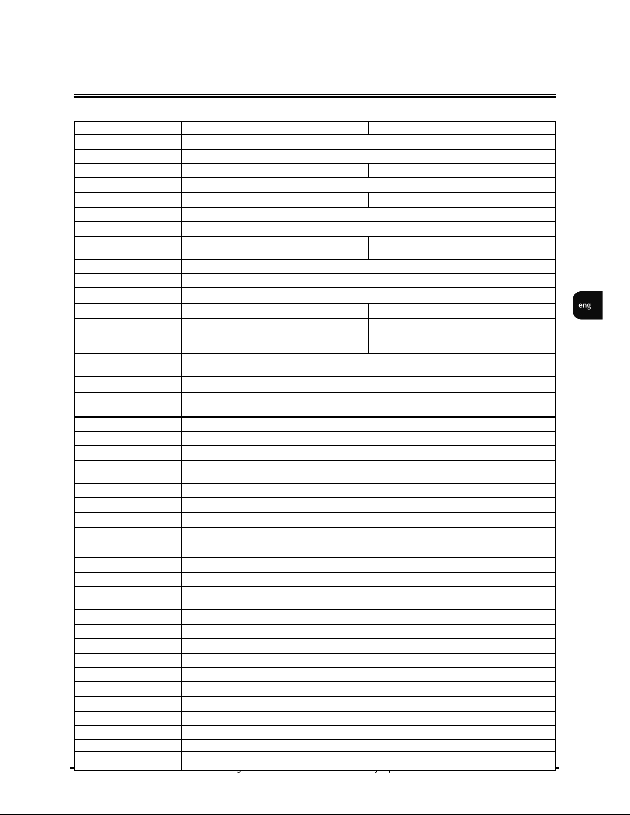
1.2. RECORDER’S TECHNICAL DATA
Model
NDR-HA4208
NDR-HA4416
Operation Mode
QUADRUPLEX
Operating System
Linux
Video Input
8 x BNC, loop-through
16 x BNC, loop-through
Video Output
Main Monitor (1 x BNC, 1 x VGA), Spot Monitor (1 x BNC)
Alarm Input
8
16
Alarm Output
2 relays
Audio Input/Output
2 x RCA / 1 x RCA
Recording Speed
200 fps (360x 288), 100 fps (720 x 288), 50 fps
(720x576),
Compression
H.264 - own algorithm
Recording Resolution
720x 576,720 x 288, 360 x 288
Recording Mode
Time-lapse, Event (Alarm, Motion detection and/or “Text-in”)
Display Speed
200 fps (real-time)
400 fps (real-time)
Display Screen
Full screen, 4, 9, PiP, sequence, user defined, freeze
image function, digital zoom of a chosen screen
area: 2x
Full screen, 4, 9, 16, PiP, sequence, user defined,
freeze image function, digital zoom of a chosen
screen area: 2x
Motion Detection
768 detection windows (24x32 grid) with sensitivity & active areas cells number needed for alarm
activation defined individually for each channel
Video Loss Detection
Yes
Schedule Recording
Individually adjustable for each day/specific days (holidays etc.) per camera, combination of individual
recording modes possibility
Recorded Data Search
By date/time or events (motion, disappeared object, “Text-in”)
Event History Log
Up to 5 000 system events and unlimited alarm events
Time Synchronization
Automatic time synchronization with NTP server
System Diagnostic
Automatic control of HDD bad sectors number (“Health”) & temperature status with local and network
notification function
Storage
Supports up to 3 internal HDDs , 1 HDD 500 GB in-set included
Backup
Onto CD/DVD, HDD or USB Flash Memory through USB port, through the network
DVD-RW Drive
Not included
External Ports
1 x Ethernet - RJ-45 interface, 10/100 Mbit/s, 2 x USB 2.0 for external drives (HDD, PC mouse, Flash
Memory), 1 x RS-485 for PTZ cameras or NV-KBD70, NV-KBD60 & NV-KBD30 keyboards,
1 x RS-232 for POS, ATM, AC etc.
PTZ Functions
PTZ cameras control directly from the device and through the network (RASplus, IE)
Protocol
Novus-C, Novus-C1, Pelco-D and others
Control
Front panel, Network (RASplus, IE), NV-KBD70,NV-KBD60, NV-KBD30 keyboards, USB PC mouse,
Remote Control
Set-up
Multi-lingual On Screen Display (OSD)
Software
RASplus
User Authorization
Creation of user groups and accounts with diverse grants, password protection
Auto System Recovery
Hardware WATCHDOG function
Power Supply
100~240 VAC
Power Consumption
Approx. 90 W with 4 HDDs
Operating Temperature
5°C ~ 40°C
Relative Humidity
0% ~ 80% (non-condensing)
Dimensions (mm)
430 (W) x 88 (H) x 405 (D)
Weight
7.6 kg (without HDD)
Rack Mount
Standard EIA 19”, 2U
400 fps (360 x 288), 200 fps (720 x 288), 100 fps
(720x576),
FOREWORD INFORMATION
Page 8

NDR-HA4208 / NDR-HA4416 1.2 version - User’s manual
All rights reserved © NOVUS Security Sp. z o.o.
8
Unpack the device carefully.
After unpacking please ensure that package contains the following items:
If any of the elements has been damaged during transport, please pack the items back into the original
packaging and contact your supplier.
ATTENTION!
If the device was brought from a location with lower temperature, please wait until it reaches the
temperature of location it is currently in. Turning the device on immediately after bringing it from a
location with lower ambient temperature is forbidden, as the condensing water vapour may cause shortcircuits and damage the device as a result.
Note: Please get familiarized with description and functions of rear panel inputs.
2. STARTING THE DEVICE
2.1. Getting ready to work
NDR-HA4208 / NDR-HA4416 recorder.
Rack mounting bracket with screws for install-
ing additional HDDs.
Power cord.
CD with a user’s manual and
network software.
User’s manual and network
software guide
STARTING THE DEVICE
Remote controller
Page 9

NDR-HA4208 / NDR-HA4416 1.2 version - User’s manual
All rights reserved © NOVUS Security Sp. z o.o.
9
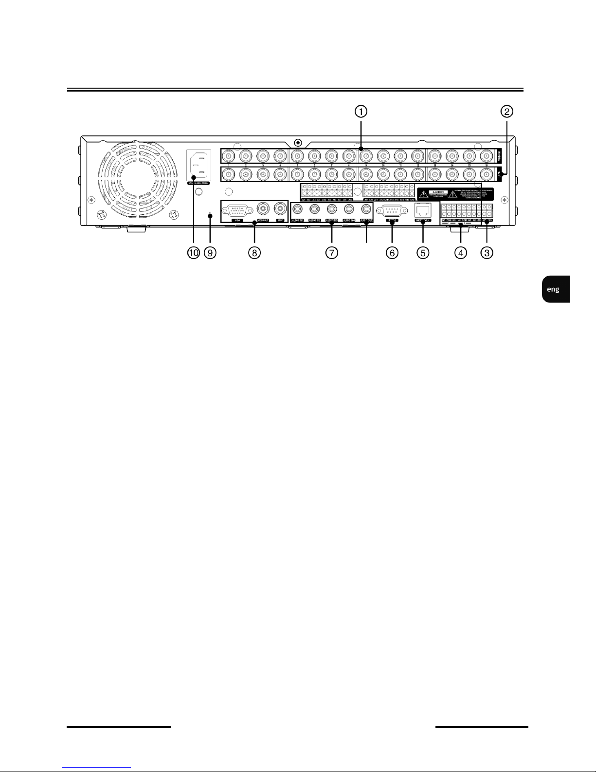
2.2. Electrical connection and other rear panel elements
NDR-HA4416 rear view
Fan cooling power supply unit, please do not cover!
1,2. VIDEO IN/LOOP: video inputs with loop-through outputs, for connecting video signal
sources with the DVR ( 16 or 8 channels depending on the model).
3. RS-485: RS-485 bus connector for remote controlling of speed dome cameras
or NV-KBD30, NV-KBD70 keyboard systems. Only one of the
aforementioned devices may be connected in the same time.
4. ALARM INPUTS: 16 or 8 (depending on a model) alarm inputs, which may be set either as
normal open (N.O.) or normal closed (N.C.). In order to detect the alarm
signal it should last 0.5sec at least. All GND connectors are common
grounded. The ground of the alarm device needs to be connected to one of
the GND connectors.
ALARM OUTPUTS The DVR is capable of activating external devices such as buzzers, halide
lamps, sirens etc. via its relay outputs. Max current for the output is 1A for
30VDC and 0.5 A for 125VAC.
ARI (Alarm Reset Input): External signal applied to ARI and GND connectors is able to
deactivate active relay output together with the internal buzzer of the
recorder. The voltage of the applied signal should be at least 0,3V and last
for about 0,5sec.
STARTING THE DEVICE
Page 10

NDR-HA4208 / NDR-HA4416 1.2 version - User’s manual
All rights reserved © NOVUS Security Sp. z o.o.
10
NDR-HA4416 rear view
STARTING THE DEVICE
5. NETWORK: RJ-45 connector for connecting the DVR to the computer network in
10/100Mb/s standard.
6. RS-232 PORT: Allows for connection of modems for remote video preview, connection o f
external keyboards (optional) or devices generating the ASCII codes for
additional information (cash registers, ATM machines). Only one of the
devices may be connected at once. If transmission standard of connected
device is different than RS-232, you need to use additional device (e.g. such
as NVRS-001RSC) to change standard transmission from RS-485 to RS-
232.
7. AUDIO IN : 4 audio mono inputs (RCA type) for connecting microphones.
Note: sound recording may be conducted only when law regulations of
a given country allow for such activities.
Audio inputs are not equipped with pre-amplifiers, so connecting the
microphones directly to the inputs is not advised. Usage of preamplifiers is
recommended.
AUDIO OUT: Audio output for connecting speaker and amplifier. Connecting the speaker
directly to the outputs is not advised. Usage of pre-amplifier is
recommended.
Attention: Cord used for connecting to RS-232 port is not included with the set.
Make sure that the cord you have is appropriate. (DB9S female connector).
Page 11
NDR-HA4208 / NDR-HA4416 1.2 version - User’s manual
All rights reserved © NOVUS Security Sp. z o.o.
11
STARTING THE DEVICE
Widok NDR-HA4416
8. SPOT 1 BNC outputs for SPOT monitor allowing for full screen display of any
camera or sequence of cameras;
VIDEO OUT, Main monitor connectors, BNC or VGA type. VGA output allows for
connecting the main monitor in the computer mode. Please use signal cord
provided with the monitor when using said connection type.
9. RESET
10. Power socket for connecting 100 ~ 230 V AC, please ensure that the plug
is sitting firmly in the socket and that the power socket in the wall is
equipped with a grounding pin. Do not bend the power cable excessively.
Page 12
NDR-HA4208 / NDR-HA4416 1.2 version - User’s manual
All rights reserved © NOVUS Security Sp. z o.o.
12
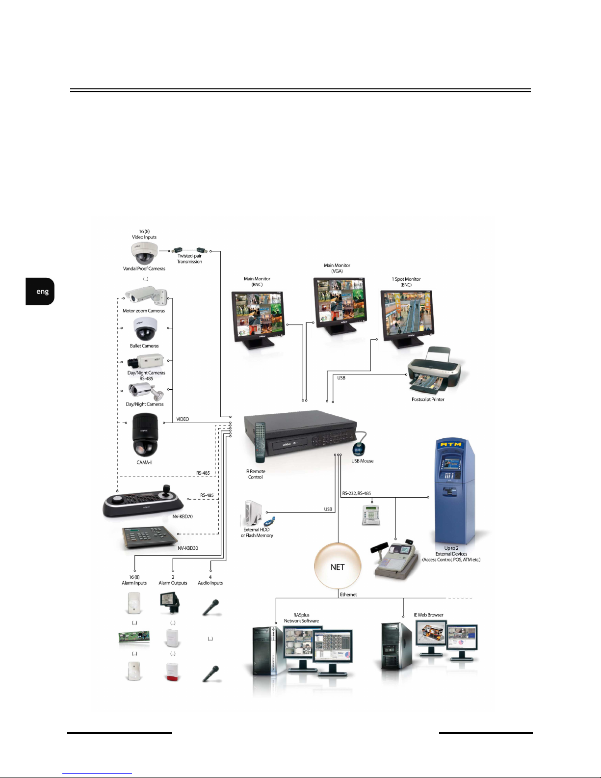
2.3. Connecting peripherals
System connection should be performed only by qualified personnel. Please familiarize yourself with
the scheme located below, depicting possible implementation of the DVR in the system, before
installation.
Depending on requirements, each system will have different number of peripherals connected.
Monitors, cameras etc. should be purchased separately, depending on current needs. Detailed
description of peripheral connections can be found in the following chapters of this manual.
STARTING THE DEVICE
Page 13
NDR-HA4208 / NDR-HA4416 1.2 version - User’s manual
All rights reserved © NOVUS Security Sp. z o.o.
13
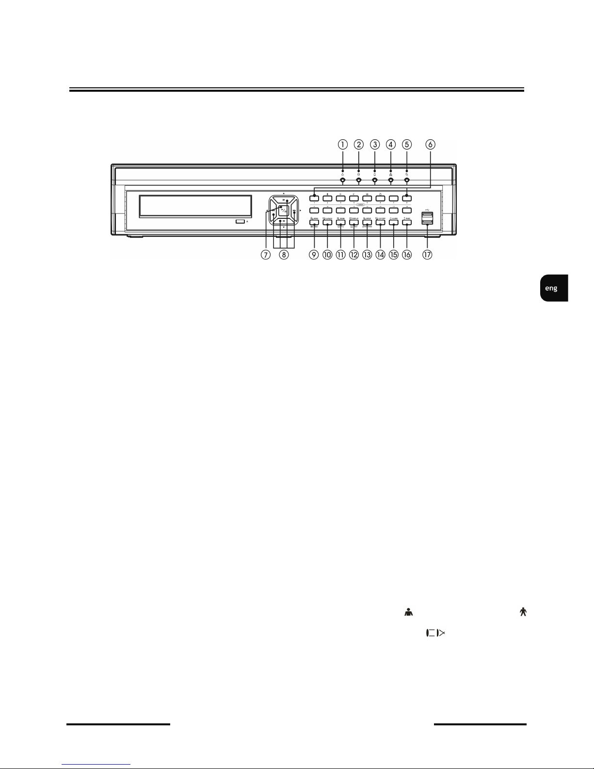
2.4. Front panel description
NDR-HA4416 View
STARTING THE DEVICE
Some buttons of the front panel are used for different functions. Below, you have the description of all
buttons and their functions.
NOTE: a mouse with USB interface can be used for recorder’s control and setting. All the details can
be found in the following chapters of the manual.
1. POWER LED When solid red, indicates that the device is turned on
2. HDD LED Flashing LED indicates that the HDD is either in recording or
playback mode.
3. ALARM LED Solid light when alarm has been triggered and / or internal
buzzer is active.
4. NETWORK LED Flashing of NETWORK LED means that the device is connected
to Ethernet or external modem.
5. CLIP COPY LED Emits solid light when copying is in progress.
6. CHANNEL BUTTONS Press one of the channel buttons to display required camera in full
screen mode. Channel buttons are used for setting and entering the
password. Holding any channel button for 3 seconds allows to
enter image setting menu (brightness, contrast, saturation, hue).
In PTZ mode press 1 button to zoom in , button 2 to zoom out
Buttons 3 and 4 set the sharpness, button 5 e n a b l e s
PRESET function, button 6 saves PRESET.
Page 14
NDR-HA4208 / NDR-HA4416 1.2 version - User’s manual
All rights reserved © NOVUS Security Sp. z o.o.
14
7. PLAY / PAUSE Press the PLAY/PAUSE button to play stored images at normal
speed. Pressing the button in the Playback mode pauses the
video.
8. Used for navigating through OSD menu, and changing parameter
values with and buttons. In PTZ mode navigation buttons
are used for speed dome cameras control.
In PIP mode and buttons are used for changing the
position of PIP window. and buttons are used to change
size of the PIP window.
In DISPLAY mode pressing fast playback butons
buttons speeds up the playback, with the speed indicated by
icons visible on the screen.
press or in PAUSE mode to watch picture frame by frame.
9. MENU/CAMEO Press MENU button to enter the DVR menu.
Pressing and holding MENU button for 2 seconds while in screen
division display mode starts sequence display. Function allows to
change the sequence of camera display in screen division mode on
the main monitor or start sequence display on the SPOT monitor
fullscreen.
10. PLAYBACK Press PLAYBACK button to enter or exit Playback mode.
▲ ▼
▲ ▼
► ◄
STARTING THE DEVICE
Page 15
NDR-HA4208 / NDR-HA4416 1.2 version - User’s manual
All rights reserved © NOVUS Security Sp. z o.o.
15
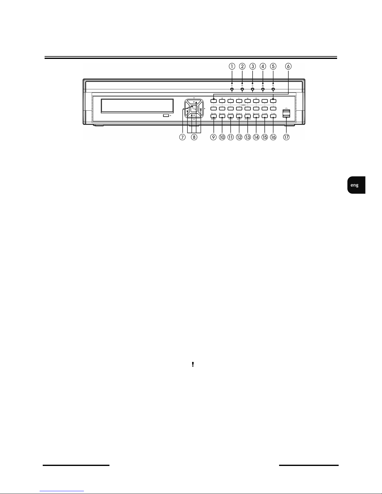
11. ZOOM/PTZ Press the ZOOM button to zoom the currently displayed image.
A rectangular PIP displays the zoomed-in area. Please use
the arrow buttons to move the rectangle through the screen.
Press the PTZ button to enter the PTZ (Pan/Tilt/Zoom) mode
which allows for remote camera controlling.
12. DISPLAY Toggles between different display formats. The available formats
are: full, 4x4, 3x3, 2x2 and PIP. Press and hold DISPLAY
button for 2 seconds to display selected camera on the SPOT
monitor.
13. SEQUENCE Consecutive pressing of the SEQUENCE button while in full
screen live camera display successively switches between the
cameras. Press and hold SEQUENCE button for 2 seconds to
start automatic sequence display.
14. CLIP COPY CLIP COPY button allows to copy selected recordings onto
DVD or Flash type memory.
15. ALARM Press ALARM button to deactivate internal buzzer and active
relay outputs. Pressing ALARM button in live mode opens event
register. This function may be password protected.
16. PANIC Pressing the PANIC button starts recording on all channels,
and displays on the main screen.
17. USB USB port for Mouse, Printer , POS or Flash memory.
STARTING THE DEVICE
Page 16

NDR-HA4208 / NDR-HA4416 1.2 version - User’s manual
All rights reserved © NOVUS Security Sp. z o.o.
16
Remote Controller
NOTE: For simplicity, the button descriptions in this manual refer to the front panel buttons.
2.5 HDD installation
DVR’s NDR-HA4208 i NDR-HA4416 supports up to 4 hard disks (3 HDDs with DVD burner).
NOTE: To obtain the latest info on compatible disks together with their maximum supported
capacities please contact your supplier or visit the www.novuscctv.com website.
NOTE: HDDs previously used in any other device need to be formatted. Please keep that in
mind due to the possibility of important data loss.
ATTENTION: The list of compatible HDDs contains all the HDDs that are compatible with a
given DVR including HDDs designed to office use (desktop disks). However, due
to the fact that reliability of the recording process and data safety are most
important factors of any CCTV system, we strongly advise to use HDDs
designed for continuous (24/7) operation.
TURNING ON THE POWER
After connecting the power cord to the DVR it takes approximately 60 seconds to initialize.
STARTING THE DEVICE
Page 17
NDR-HA4208 / NDR-HA4416 1.2 version - User’s manual
All rights reserved © NOVUS Security Sp. z o.o.
17
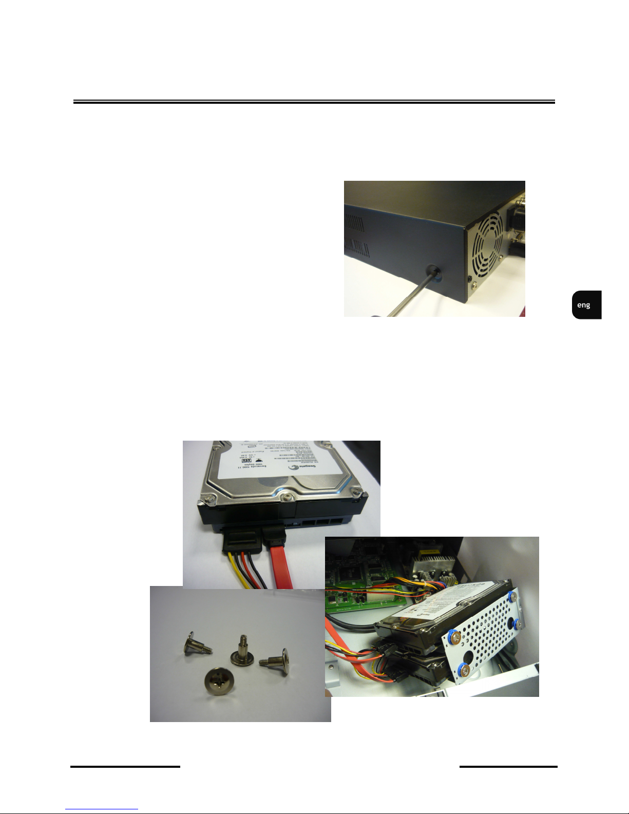
Before installing a hard drive (HDD), DVD drive (ODD), please make sure the power is disconnected
from the DVR. A factory recommended HDD, ODD should be used for this installation.
To install a HDD, ODD on your DVR :
1. Remove the lid of the DVR by unfastening the
screws.
2. Install the HDD in the HDD rack using the provided screws. Connect power and SATA cables to
the HDD.
STARTING THE DEVICE
Page 18

NDR-HA4208 / NDR-HA4416 1.2 version - User’s manual
All rights reserved © NOVUS Security Sp. z o.o.
18
STARTING THE DEVICE
3. Install the ODD in the ODD rack using screws provided by ODD manufacturer. Connect power
and SATA cables to the ODD.
4. Connect HDD, ODD to the motherboard of the DVR with the included SATA cables.
5. Re-install the lid of the DVR and fasten screws.
Page 19
NDR-HA4208 / NDR-HA4416 1.2 version - User’s manual
All rights reserved © NOVUS Security Sp. z o.o.
19
3. RECORDER’S MENU
NDR-HA4208 and NDR-HA4416 digital multiplexers feature an multilingual OSD menu allowing for
adjusting the settings of the device.
The difference between 8– and 16-channel versions lies in the number of channels and recording
speed.
Prior to using DVR for the first time, initial setup is strongly advised. This includes setting such parameters as time and date, language version, camera, audio, remote control, record mode, network and
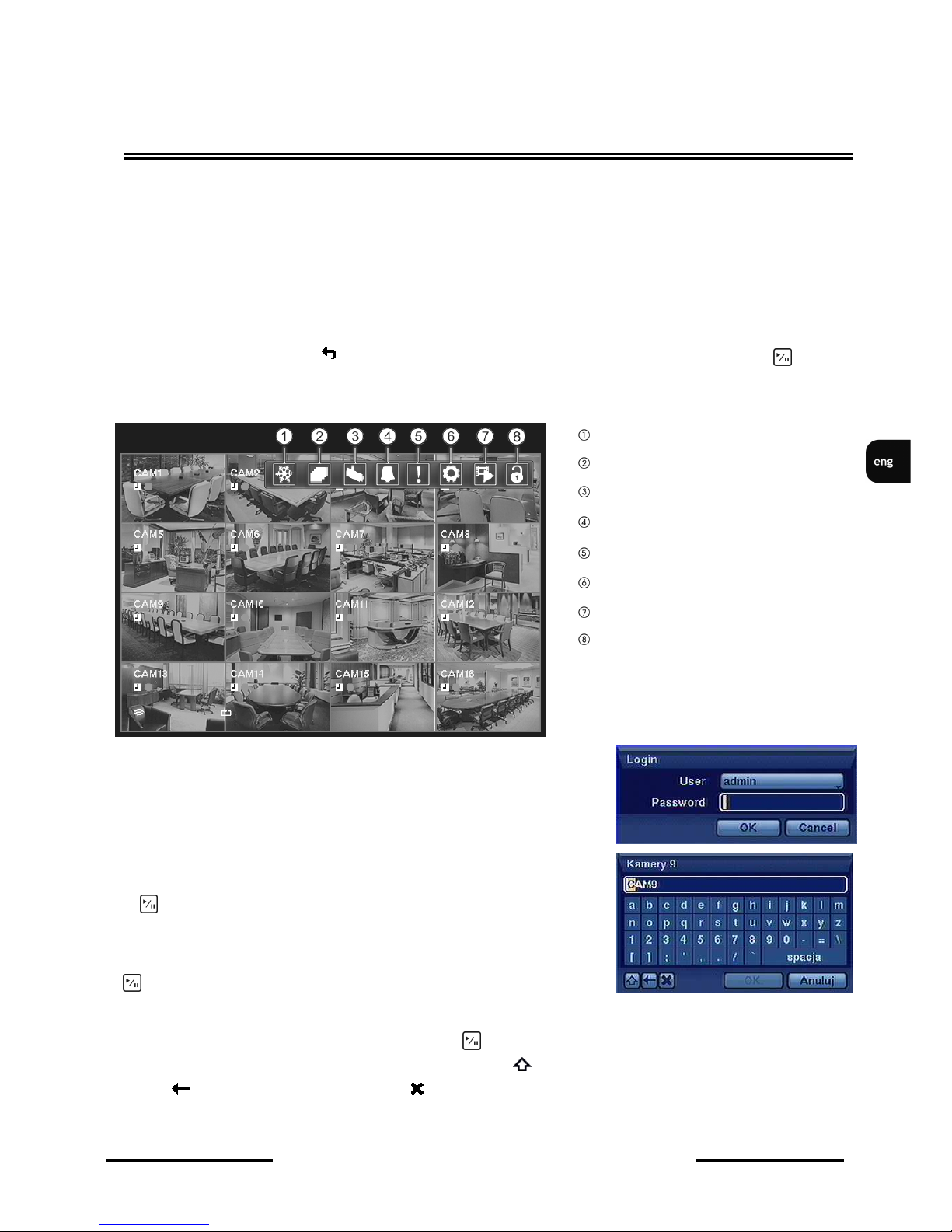
password. Highlighting the icon visible in most of the menus/submenus and pressing b u t ton resets the parameters available on that screen to their default values.
NOTE: The Live Monitoring menu can be alternatively displayed by
moving the mouse pointer to the top of the screen.
There is no default password when logging in for the first time as
the admin user! Please leave the password field void and press
the button
Arrow buttons navigate through the menu.
To confirm selection, enter sub-menus and change values use
button .
Parameter changes are performed via arrow buttons.
A virtual keyboard is available whenever the need for entering names and titles arises. Use the arrow
keys to highlight the desired character and press button. The selected character appears in the title
bar and the cursor moves to the next position. Pressing toggles between the upper and lower case
letters, serves as the backspace, and deletes entered characters. Up to 31 characters including
spaces can be used for creating title.
RECORDERS MENU
Freeze
Sequence
Camera Menu
Alarm Reset
Panic
Setup
Search Mode
Login/Logout
Page 20

NDR-HA4208 / NDR-HA4416 1.2 version - User’s manual
All rights reserved © NOVUS Security Sp. z o.o.
20
3.1. System menu
After pressing MENU button and entering user password the following screen appears:
System menu contains six sub-menus regarding the system settings.
3.1.1. Information
After choosing this sub-menu and pressing the following screen appears:
Highlight the Site box and press button. A virtual keyboard appears for entering a SITE name.
Highlight the box beside System ID and press button.
NOTE: The Unit ID number is used to identify the unit when it is connected to other DVRs through
the RS-485 port or when using remote control. You cannot set the same ID number for two or more
DVRs which are in the same RS-485 network. It is possible to have multiple DVRs with Unit ID 0 that
are in the same area as long as they are not part of an RS-485 network. In such case, all DVR’s will be
controlled at the same time when using the infrared remote control.
RECORDER’S MENU
Page 21
NDR-HA4208 / NDR-HA4416 1.2 version - User’s manual
All rights reserved © NOVUS Security Sp. z o.o.
21
Highlight the box next to Language text and press button. Available languages should be displayed
in the drop-down list. Highlight the desired language and press button.
To upgrade the software, connect a USB device with upgrade package file to the DVR. Highlight
Upgrade… and press button. The Upgrade screen should appear displaying the upgrade package file
names that are available. The “.rui” indicates that the file is for software upgrades and “.ofi” indicates
that the file is for optical drive’s firmware upgrades. Select the desired file and press the button.
Highlight the Install button and press button to install selected software package. Highlight Cancel
button and press button to close the window without upgrading. If the upgrade package file is not
installed properly, you will get an error message. The system restarts automatically after completing
upgrade.
NOTE: The Upgrade button will be deactivated if hard disk drive has not been formatted as it requires
the space for temporary files when upgrading the system.
CAUTION: The USB device must be FAT16 or FAT32 formatted.
Use Import/Export buttons to import or export system settings.
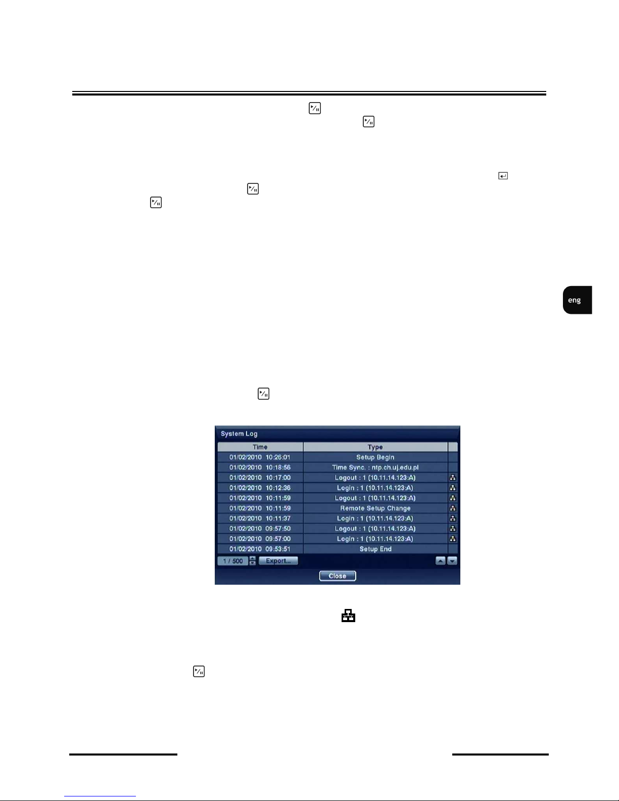
3.1.1.1. System log
Highlight Show System Log… and press
button to display the System Log
The System Log screen lists system activities (up to 5,000 starting from most recent) that have
occurred, along with their appropriate time and dates. The icon will be displayed in the last column
for system activities of the remote site. Scroll through the log pages using Up and Down arrows.
Alternatively, going directly to desired log page by entering the log page number in the box at the
bottom left of the screen is also possible. EXPORT button allows for exporting all logs to text file.
Highlight Close and press button to exit the screen.
RECORDER’S MENU
Page 22
NDR-HA4208 / NDR-HA4416 1.2 version - User’s manual
All rights reserved © NOVUS Security Sp. z o.o.
22
RECORDER’S MENU
3.1.1.2. Recorded data
RECORDED DATA field informs about time frame in which the recordings were made.
Selecting and confirming CLEAR ALL DATA field deletes all recordings currently stored on the HDD.
Prior to deletion, user will be informed about irrecoverable data loss.
Deletion of recordings doesn’t remove entries from system log, therefore entries with no associated
video may occur.
3.1.2. Date / time
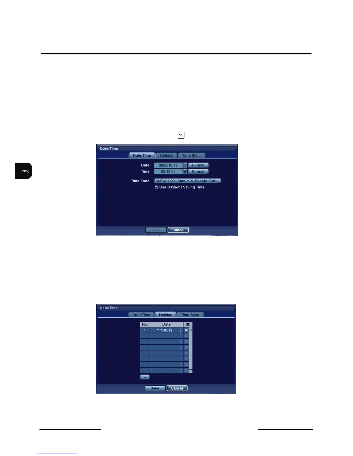
Highlight Date/Time in the System menu and press button. The Date/Time setup screen appears.
This submenu is responsible for adjusting the date and time using navigation and ENTER buttons.
Please select appropriate date/time format, adjust time settings and select time zone the DVR will work
in.
NOTE: Changes are applied at the moment of pressing SAVE button.
To automatically update time settings according to DST change, please check the USE
DAYLIGHT SAVING TIME option.
Highlight the Holiday tab, and the Holiday setup screen appears.
HOLIDAY tab allows for defining special days, e.g. holidays, when the DVR will be working in a
specially defined mode, other than the default one. Days described as holidays may be used in creating
record schedule.
Page 23
NDR-HA4208 / NDR-HA4416 1.2 version - User’s manual
All rights reserved © NOVUS Security Sp. z o.o.
23
RECORDER’S MENU
NOTE: Movable feasts should be updated each year.
To add a new holiday, please select + icon. Current date (as set in the DVR) should appear on the
list. Please select desired month and day using navigation buttons. By pressing previously
entered date may be deleted.
TIME SYNC. tab allows for defining external time servers (via entering their IP addresses),
which will update the time and date of the DVR in desired intervals (from 30 minutes up to 1
day). LAST SYNC-TIME field informs about the latest update.
When a particular monitoring system utilises more than one DVR, one of the devices may be set up as
a time server for the rest. In order to do so, please check the RUN AS SERVER, box, set the rest of
the DVRs to the AUTOMATIC SYNC. and enter the IP address of DVR-server in the TIME
SERVER field.
Note: Please provide the devices with proper classes of IP addresses.
Time sync function is especially useful in dispersed systems, when a necessity of synchronizing time
with external devices (e.g. cash registers or ATMs) arises.
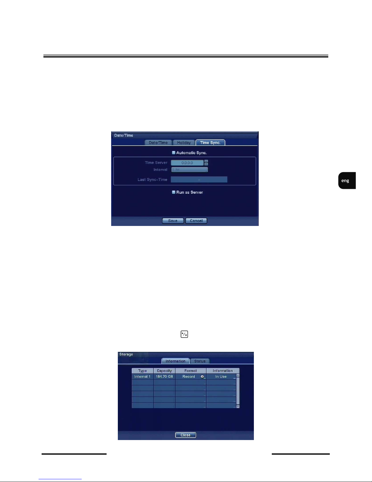
3.1.3. Disks
Highlight Storage in the System menu and press button. Storage setup screen appears and displays
information about DVR’s storage devices.
Page 24

NDR-HA4208 / NDR-HA4416 1.2 version - User’s manual
All rights reserved © NOVUS Security Sp. z o.o.
24
TYPE column describes type of storage device (internal disk, external disk with USB interface).
Capacity of the storage device is displayed in the CAPACITY column.
FORMAT column informs if the device is used for recording (Record) or not. Unformatted indicates
that device is not formatted. icon indicates that the storage device (HDD) creates temporary
partition serving as the buffer space during CD/DVD-RW backup data burning. Burning the stored
data without the buffer space is not allowed.
To format the disk, highlight the box in the Format column for the desired storage device and press
button.
USE AS switches the storage device between recording and archiving modes.
PARTITION allows for enabling the buffer space to store temporary files for CD/DVD burning by
checking the appropriate option.
The INFORMATION column displays whether the device is being used or not. Other indicates the
storage device has been previously used in a different device.
Highlight the box in the INFORMATION column for the desired storage device and press button.
You will be able to check the time information of recorded data.
If you want to erase recorded data stored on the selected device, highlight Clear and press button.
You will be asked whether or not you want to delete the data.
NOTE: External disks with USB interfaces can be used only for copying data.
NOTE: When disconnecting an USB hard disk drive from the DVR, highlight Don’t Use first and then
disconnect the device.
Do NOT disconnect the USB cable or the power from the device while copying video clips. If the USB
cable is disconnected while copying, video clips may be lost as a result.
RECORDER’S MENU
Page 25

NDR-HA4208 / NDR-HA4416 1.2 version - User’s manual
All rights reserved © NOVUS Security Sp. z o.o.
25
Highlight the Status tab, and the Storage Status screen displays:
TYPEcolumn displays the type of storage device.
DISK BAD displays information about percentage of bad sectors existing on the HDD.
TEMPERATURE field contains information about current HDD temperature.
S.M.A.R.T. (Self-Monitoring Analysis and Reporting System) monitors current HHD operation:
• GOOD - proper HDD operation,
• BAD - data cannot be read/written to HDD,
• N/A - HDD works properly, but SMART function is inactive.
NOTE: Temperature and S.M.A.R.T. information will be available only for hard disk drives
supporting SMART (Self-Monitoring Analysis and Reporting Technology) monitoring program.
When the storage condition is “Bad”, Event Status – Storage screen displays and you can check the
storage condition for details. Once “Bad” message displays, replacing the hard disk drive is
recommended, usually within 24 hours.
RECORDER’S MENU
Page 26
NDR-HA4208 / NDR-HA4416 1.2 version - User’s manual
All rights reserved © NOVUS Security Sp. z o.o.
26
RECORDER’S MENU
3.1.4. Users
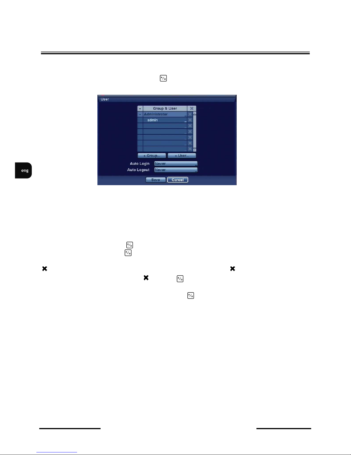
Highlight User in the System menu and press button. User setup screen displays authorized groups
and users.
You can add and delete groups and users. When adding a group, you can assign privileges to the group.
The +/- column is used to collapse and expand user groups. Selecting and confirming any position
from the first column marked + or - allows to display only group names (selected group) or group
names (selected group) and names of particular users.
The administrator group and the user admin are default recorder’s settings and cannot be deleted. All
users of the Administrator group have all administrator’s rights by default.
Highlight Group Name and press button to change the authority levels assigned to the group.
Highlight User Name and press button to add or change the password assigned to that user. You can
also change the group to which the user is assigned.
column can be used to delete a User Name or an entire Group. If the is grayed out, that Group or
User cannot be deleted. Highlight the and press button. You will be asked to confirm that you
want to delete the User or Group.
To add a Group, highlight the + Group… box and press button. A virtual keyboard appears allowing
you to enter the Group name. You can use up to 15 characters including spaces in the group name.
Enter the name and assign authority levels to the group.
Page 27

NDR-HA4208 / NDR-HA4416 1.2 version - User’s manual
All rights reserved © NOVUS Security Sp. z o.o.
27
RECORDER’S MENU
A group of users can be assigned the following privileges:
• Authority — If selected, a given user has all authority levels.
• Shutdown — The user can shut the local system down.
• Upgrade — The user can upgrade the software on a local system or a PC running RAS software.
• System Time Change — The user can change the system date and time on a local system or a PC
running RAS.
• Data Clear — The user can clear all video data or format disks on a local system or a PC running
RAS.
• Setup — The user without Setup authority cannot establish any system settings excluding system
shutdown and logout on a local system or a PC running RAS.
• Color Control — The user can control brightness, contrast, hue and saturation for cameras on a
local system or a PC running RAS.
• PTZ Control — The user can control the PTZ camera on a local system or a PC running RAS.
• Alarm-Out Control — The user can reset the DVR’s outputs including the internal buzzer during
an alarm by pressing the ALARM button on a local system or alarm-out control button on a PC
running RAS.
• Covert Camera View — The user can view video from cameras set as Covert while in the Live
Monitoring or Search mode on a local system or a PC running RAS.
• System Check — The user can view the remote system status or check the remote system status
as a batch process on a PC running RAS.
• Record Setup — The user can establish all Record settings on a local system or a PC running
RAS.
• Search — The user can access the Search mode on a local system or a PC running RAS.
• Clip-Copy — The user can copy video clips on a local system or a PC running RAS, and save
video data in an AVI, bitmap or JPEG file format.
Highlight the box beside AUTO LOGIN to select a User to be automatically logged in when the DVR
is powered up.
Highlight the box beside AUTO LOGOUT to select time in which user will be automatically logged
out. The options are: Never, 1 min., 3 min., 5 min., 10 min., 15 min., 20 min., 25 min., 30 min. and 1
hr.
Page 28
NDR-HA4208 / NDR-HA4416 1.2 version - User’s manual
All rights reserved © NOVUS Security Sp. z o.o.
28
RECORDER’S MENU
3.1.5. System shutdown
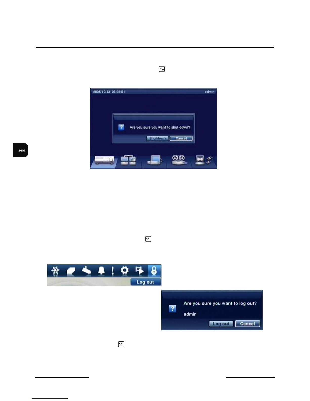
Highlight Shutdown in the System menu and press button. The Shutdown screen displays asking
you to confirm whether or not you want to shut the system down:
After confirming the intent of shutting the system down, a message informing about the
possibility of safe switching off the device is displayed.
Note: Turning off the device in a way other than described above is not allowed, and may result
in data loss or even damage to the equipment itself.
3.1.6. User logout
Highlight Logout in the System menu and press button. The Logout screen confirmation appears:
After selecting Logout and pressing button, user is logged out and camera image is displayed on the
screen.
Page 29
NDR-HA4208 / NDR-HA4416 1.2 version - User’s manual
All rights reserved © NOVUS Security Sp. z o.o.
29
RECORDER’S MENU
3.2. Network
NETWORK menu contains two submenus allowing for configuring network settings and event
confirmation.
3.2.1.1. Network
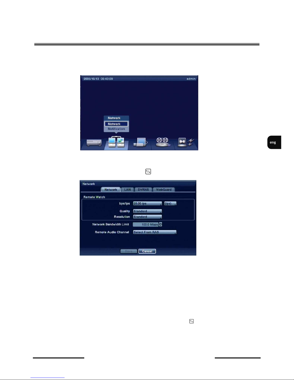
Highlight Network in the Network menu and press button. Network setup screen appears.
TRANSFER SPEED field in the NETWORK tab allows for configuring the speed of image
transmission - from 50 Kbps to 100 Mbps, or from 0,1 to 25 images per second (ips). Defined value is
the maximum theoretically possible, but in reality depends directly on the settings of particular network
devices and bandwidth quality of the network system.
In the QUALITY field you can select one of the available qualities: Very High, High, Standard and
Low. Settings selected here do not influence the quality of recorded images. Lower quality of images
which are broadcasted through the network grants higher refreshing frequency at the same level of
bandwidth.
The DVR supports two-way audio communication between a local system and a PC running RAS.
Highlighting the box next to Remote Audio Channel and press the button, therefore allowing to
select the channel sending audio stream to the remote site. Selecting Select From RAS will send audio
of the channel selected from RAS.
Page 30
NDR-HA4208 / NDR-HA4416 1.2 version - User’s manual
All rights reserved © NOVUS Security Sp. z o.o.
30
3.2.1.2. LAN
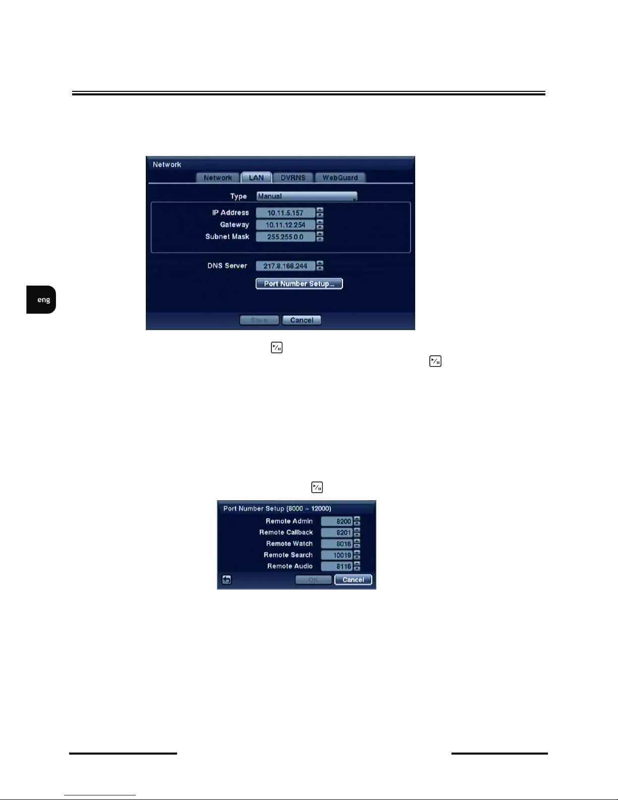
After selecting LAN tab, the following setup screen appears:
Highlight box next to Type field and press button. You can select type of the network configuration
from: Manual, DHCP and ADSL (with PPPoE). Select desired type and press button.
Select Manual from the Type to set up LAN parameters manually. You will need to get the appropriate
IP Address, Gateway and Subnet Mask from your network administrator.
The factory default LAN settings are:
IP Address: 192.168.1.129
Gateway: 192.168.1.254
Subnet Mask: 255.255.255.0
Highlight PORT NUMBER SETUP box and press button. The Port Number Setup screen appears.
Change the numbers by highlighting them and using Up and Down arrow buttons to increase or
decrease value. The system restarts automatically after changing port settings.
The factory default Port settings are:
Remote Admin: 8200
Remote Call-back: 8201
Remote Watch: 8016
Remote Search: 10019
Remote Audio: 8116
RECORDER’S MENU
Page 31

NDR-HA4208 / NDR-HA4416 1.2 version - User’s manual
All rights reserved © NOVUS Security Sp. z o.o.
31
NOTE: Do NOT use the same port number for two different programs, otherwise, DVR cannot be
connected with a PC running RASPlus.
Changing port settings, you must change the port settings on the PC running RASPlus as well. Refer
to the RASPlus manual for details.
For the ADSL network connection with PPPoE protocol you need to manually configure connection
parameters as far as ID number and passwords are concerned.
NOTE: The ADSL and modem cannot be configured at the same time. If DVR is configured by
modem, the ADSL (with PPPoE) will not be selected.
Entering the ID and Password and highlighting OK reads the current IP address of the DVR configured
by ADSL network. If DVR is configured by DHCP or ADSL network, the IP address might change
whenever the unit is turned on.
3.2.1.3. DVRNS
Function unavailable in current firmware version.
3.2.1.3. WebGuard
This tab allows for configuring the DVR to be remotely accessible via IE 6.0 (or newer) browser. The
access to the DVR is achieved through ports ranging from 12001 to 14000. 12088 is the default port for
the IE remote access.
RECORDER’S MENU
Page 32
NDR-HA4208 / NDR-HA4416 1.2 version - User’s manual
All rights reserved © NOVUS Security Sp. z o.o.
32
RECORDER’S MENU
3.2.2. Notification
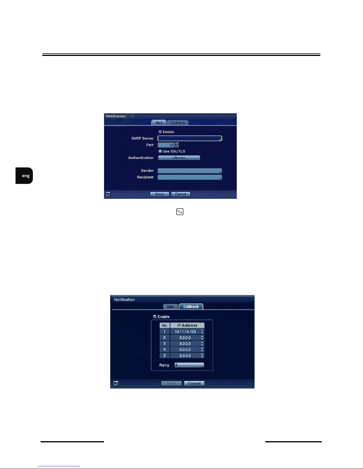
The DVR can be set up to send emails or to contact a computer running RASPlus (Remote
Administration System) when an event occurs.
3.2.2.1. E-mail
After selecting NOTIFICATION the following screen appears:
Please check ENABLE box, to activate the e-mail notifying setup.
Highlight the box beside SMTP Server and press button. Virtual keyboard apears. Enter the SMTP
Server IP address or name obtained from your system administrator. Set Port number and
Authentication.
Highlight box beside Sender and enter the sender’s e-mail address.
Highlight box beside Recipient and enter the recipient’s e-mail address.
3.2.2.2. Call-back
After selecting CALLBACK, the following screen appears:
When LAN is turned On you can change the IP addresses. Enter the IP address of the computer you
want contacted during an event. You can enter up to five IP addresses.
Highlight box beside Retry and enter the number of times you you want DVR to try contacting the
computer. You can select from 1 to 10 retries.
Page 33

NDR-HA4208 / NDR-HA4416 1.2 version - User’s manual
All rights reserved © NOVUS Security Sp. z o.o.
33
RECORDER’S MENU
3.3. Devices
You can configure the video, audio, alarm, display and remote control devices connected to the DVR.
3.3.1. Cameras
Highlight Camera in the Devices menu and press button. The Camera setup screen appears.
You can turn camera number On or Off, and you can change Title of each camera using the virtual
keyboard. You can also determine which cameras will display on monitors by selecting Normal, Covert
1 or Covert 2 from a drop-down list in Use column.
• Normal - live and playback images from the camera are displayed on the screen, together with
status icons
• Covert 1 - „live” and playback images from the camera are hidden, only the camera title and
status icon are displayed,
• Covert 2 - „live” and playback images from the camera are hidden, together with status icons.
Only the camera title is displayed.
Page 34
NDR-HA4208 / NDR-HA4416 1.2 version - User’s manual
All rights reserved © NOVUS Security Sp. z o.o.
34
RECORDER’S MENU
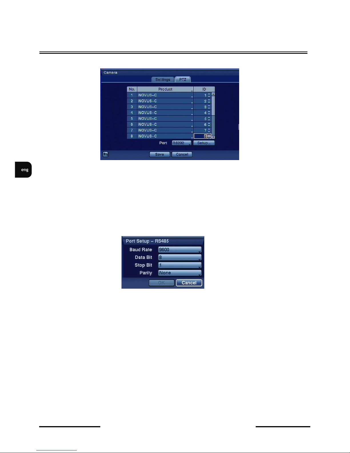
Highlight the PTZ tab, and the PTZ setup screen displays.
In order to assure a proper cooperation of the device with PTZ cameras these settings should
correspond to the camera settings. When there are no PTZ cameras in the system there is no need to
make any changes in this tab.
In PTZ tab you also define communication port settings for PTZ camera control and a given camera
protocol type and ID.
In the port position you choose telemetry port, where PTZ commands will be transmitted and define its
parameters (transmission speed, bit number, stop bit and parity).
NOTE: You cannot simultaneously connect PTZ camera control and recorder’s keyboard to the RS485 port. To connect the keyboards and speed domes cameras simultaneously you need to use RS232 /
RS485 converter.
In Product box choose one telemetry protocol from list (e.g. Novus-C, Pelco-P and Pelco-D) which is
in accordance with PTZ camera settings.
In ID box set PTZ camera number in accordance with the camera settings. It is advised to set camera
number in accordance with recorder’s camera input number.
Page 35
NDR-HA4208 / NDR-HA4416 1.2 version - User’s manual
All rights reserved © NOVUS Security Sp. z o.o.
35
RECORDER’S MENU
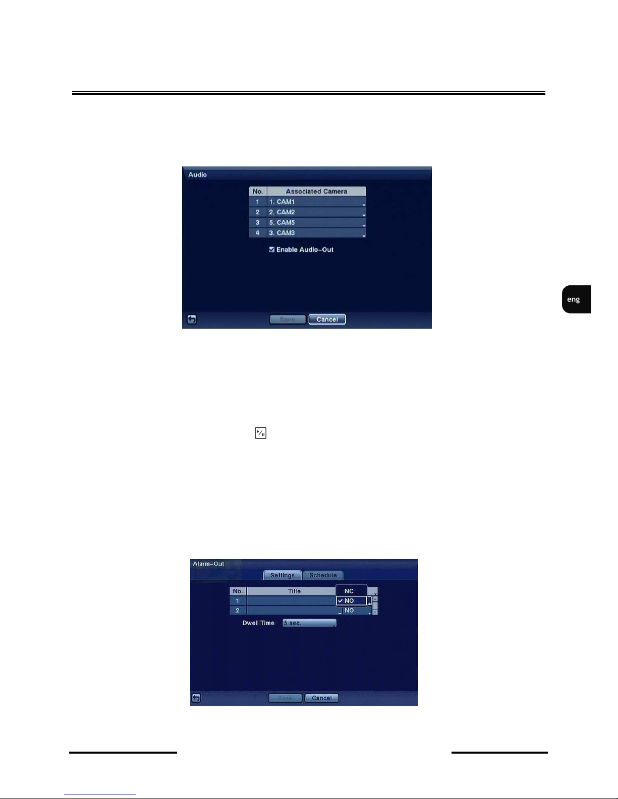
3.3.2. Audio
After selecting AUDIO submenu, the following window appears on the screen:
DVR can record up to four audio inputs.
ASSOCIATED CAMERA column allows for assigning any audio channel to any video channel.
Audio signal can originate from any place, e.g. from microphone in remote camera or a peripheral
microphone. Assignment mentioned above results in audio playing only when a full screen picture of
the video channel the audio is assigned to is displayed on the screen.
Input audio signal should be pre-amplified prior to being fed to the audio input of the DVR.
ENABLE AUDIO-OUT allows for live (or playback) listening to the audio signal in the full-screen
display mode.
Audio playback is possible only during normal playback speed .
Note: Audio recording is unavailable when the video recording speed of assigned channel is
smaller than 1 fps.
3.3.3. Alarm-out
After selecting ALARM-OUT submenu, the following window appears:
Page 36
NDR-HA4208 / NDR-HA4416 1.2 version - User’s manual
All rights reserved © NOVUS Security Sp. z o.o.
36
RECORDER’S MENU
Each alarm output can be by highlighting the box in the TITLE column and pressing button. A
virtual keyboard appears allowing you to enter the title.
Highlighting the boxes under the TYPE header allows to set the alarm output either as NO or NC
(normally open or normally closed).
Highlighting the box beside DWELL TIME and pressing button allows you to set the dwell time of
the alarm output. Dwell time ranges from 5 seconds to 15 minutes.
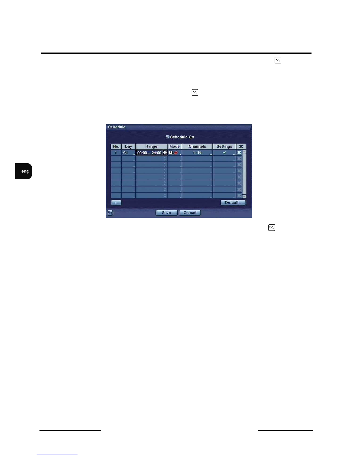
Once the Schedule tab is highlighted, the following screen will appear:
You can add and edit alarm output schedules on this screen. Highlight the + and press button to add
a schedule. The schedule may contain up to 20 entries.
The DAY box allows you to select the days that the alarm schedule will be active. The choices are:
Sun, Mon, Tue, Wed, Thu, Fri, Sat, M~F (Monday to Friday), Hol (holidays previously defined by
user in the Date/Time submenu) and All (all week).
The Range box allows you to set the time that the alarm schedule will be active in 15-minute steps
ranging from 00:00 to 24:00.
The Mode box allows you to set how the alarm reacts during the scheduled time. When set to On, the
Alarm-Out is active during the scheduled time. When set to Event, the Alarm-Out is only active when
there is an Event during the scheduled time.
The Channels box allows you to set which alarm outputs will be active. You can also select the DVR’s
internal buzzer.
The Settings column allows you to set recording parameters for schedule and event such as quality and
speed.
Page 37

NDR-HA4208 / NDR-HA4416 1.2 version - User’s manual
All rights reserved © NOVUS Security Sp. z o.o.
37
RECORDER’S MENU
3.3.4. Display
Highlight DISPLAY in the DEVICES menu and press button. The DISPLAY screen allows you to
select what information are displayed on the monitor.
Highlighting an item and pressing button toggles that item On and Off , visually represented as
checking/unchecking them.
ZOOM - icon informing about active digital zoom function.
NETWORK - icon informing about user currently remotely connected to the DVR.
FREEZE&SEQUENCE - icon informing about currently displayed picture being
„frozen”
icon informing about activated sequence display function.
SCREEN GROUP - The number of screen group displays when the DVR is not in the 4x4 display
mode of the 16-channel DVR, and 3x3 mode of the 8-channel DVR.
FREE SPACE - icon informing about active overwrite function (or percentage of free space
left, if overwrite function is off),
ARCHIVE - The icon indicates that the DVR is archiving recorded data.
DATE/TIME - displays current date / time.
USER NAME - displays name of the user that is currently logged in.
CAMERA NO. - Displays the camera number in the top-left corner of each camera screen.
CAMERA TITLE - Displays the camera title in the top-left corner of each camera screen.
RECORD - Displays icons depicting various recording modes for each of the cameras.
PTZ - The icon is displayed for each PTZ camera in its window.
TEXT-IN - Indicates that text input strings are displayed on the screen.
AUDIO - The icon is displayed on each camera screen for which the DVR can play live audio on a
local system, and the icon is displayed on each camera for which the DVR is sending
audio to a PC running RASPlus.
Page 38
NDR-HA4208 / NDR-HA4416 1.2 version - User’s manual
All rights reserved © NOVUS Security Sp. z o.o.
38
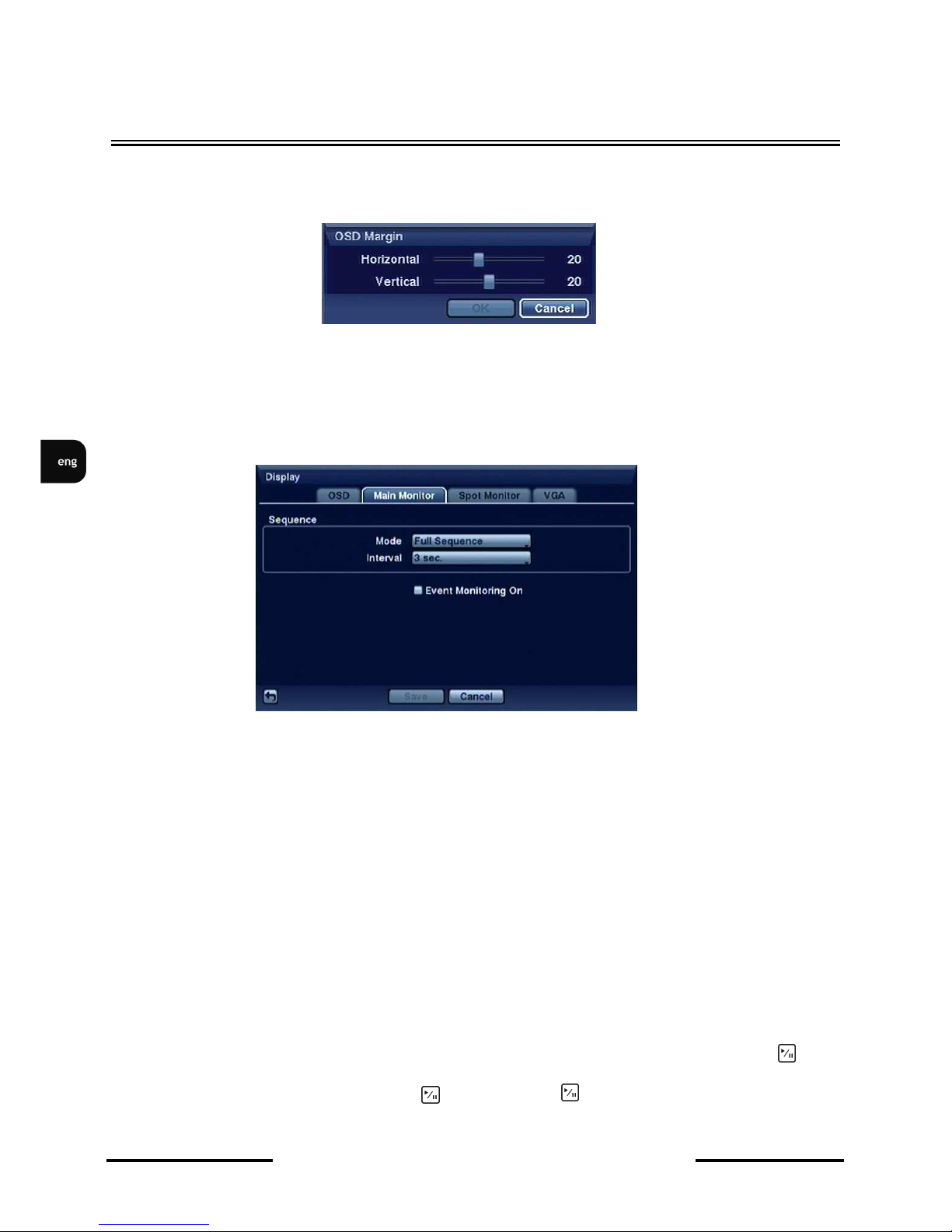
You can adjust the transparency level for the menus by highlighting Transparency and using the Left and
Right arrow buttons to adjust the value.
Once the OSD Margin tab is highlighted, the following screen will appear:
You can adjust the horizontal and vertical margins so the text and icons won’t disappear beyond the
edges of the monitor.
Highlight the Main Monitor tab to switch to the Sequence screen.
Pressing the SEQUENCE button causes the DVR to display cameras in two possible sequence modes:
“Full” and “Cameo”. In the Full mode, the DVR sequences through the cameras and displays them full
screen. In the Cameo mode, the bottom right PIP window displays the sequence images.
NOTE: Any cameras that are Off, have their video lost or are set to Covert (unless the user has authority
to view covert cameras) will be excluded from the Cameo sequence.
You can define the screen layout in a variety of formats and set the DVR to sequence through the
different screen layouts (pages) so that all the cameras will be displayed. You can also set up the DVR
to display one camera or a group of cameras all the time while cycling through the remaining cameras in
a “cameo” window. This can be done with one camera displayed full screen while displaying the cameo
window as a PIP (picture in picture), or displaying the cameras in a grid pattern with the bottom right
window as the cameo.
NOTE: Sequence cannot be used in the 4x4 display mode of the 16-channel, and 3x3 mode of the
8-channel DVR.
You can adjust the display dwell time by highlighting the box beside Interval and pressing button.
You can select dwell intervals ranging from 1 second to 1 minute.
Highlight Event Monitoring On and press button. Pressing button toggles between On and Off.
When On, the DVR will display the camera associated with the event when an event occurs.
RECORDER’S MENU
Page 39
NDR-HA4208 / NDR-HA4416 1.2 version - User’s manual
All rights reserved © NOVUS Security Sp. z o.o.
39
Widok dla NV-DVR1600
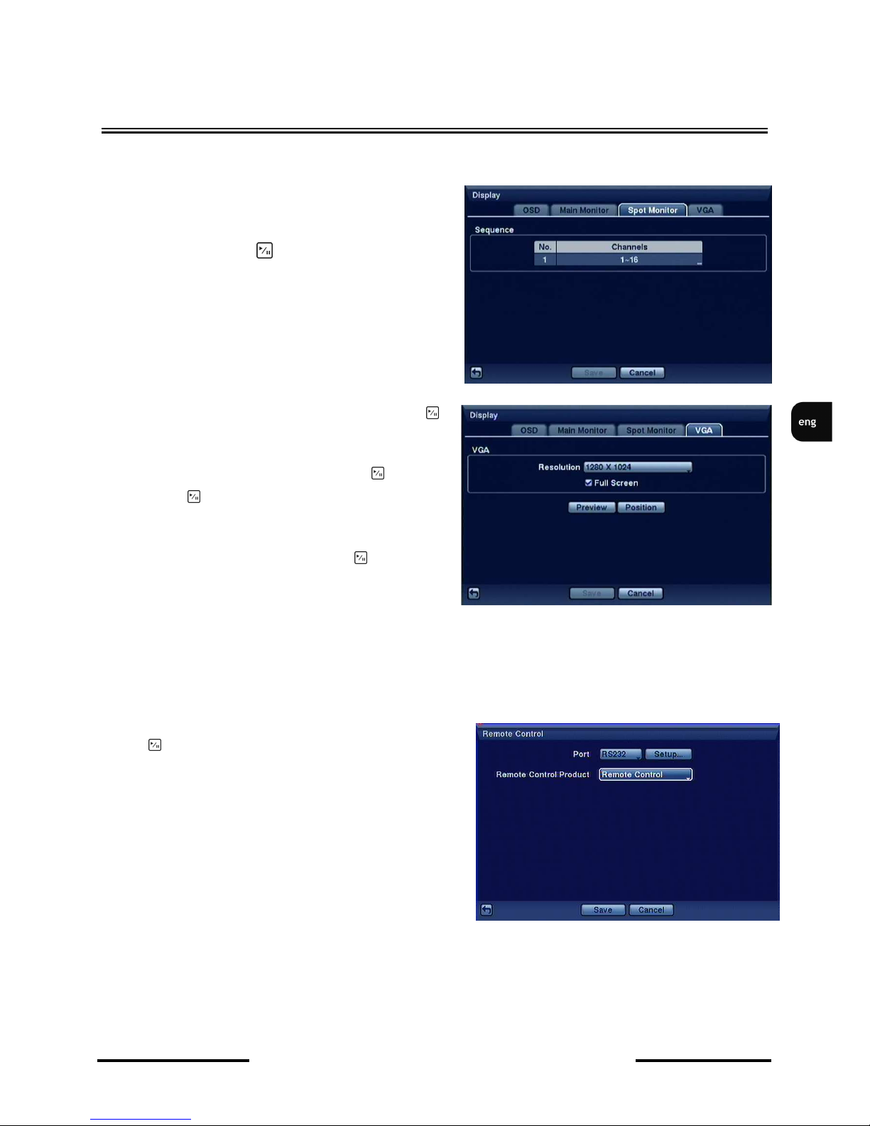
Highlight the Spot monitor tab to display the following screen:
This tab allows for setting which cameras are
sequentially displayed on the Spot Monitor. Please
highlight the box in the Channels column for the
Spot Monitor and press button.
Highlight the box beside Resolution and press the
button. 800x600, 1024x768 and 1280x1024
resolutions are available.
Highlight Full Screen and press the button.
Pressing the button toggles between On and Off.
When On, the screen on the VGA monitor operates
in full screen mode.
Highlighting Preview and pressing the button
enables the preview of functions on the VGA
monitor.
3.3.5. Remote Control
Highlight Remote Control in the Devices menu and
p r e s s button. The Remote Control setup screen
allows to select a port and properly set a remote
keyboard.
PORT field allows for selecting the remote control
port (RS-232 or RS-485), that the keyboard will be
connected to.
Note: If RS-232 or RS-485 ports are already used for
remote camera control/text input, keyboard connection
is not possible.
Highlight Setup… and select the correct Baud Rate,
Parity, Data Bits and Stop Bits for the device you are
connecting to the DVR.
Remote Control Product should be set to Keyboard in order to control the DVR via the NV-KBD70
system keyboard.
RECORDER’S MENU
Page 40
NDR-HA4208 / NDR-HA4416 1.2 version - User’s manual
All rights reserved © NOVUS Security Sp. z o.o.
40
RECORDER’S MENU
3.4. Recording
RECORD menu is divided into three submenus controlling the record settings.
3.4.1. Record
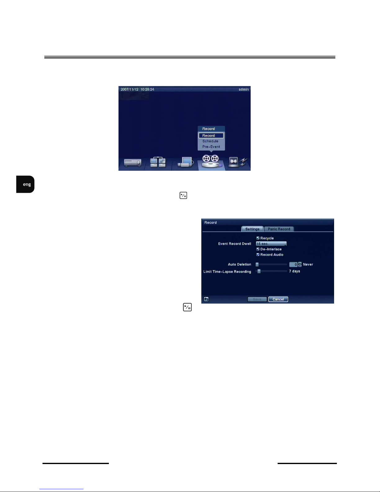
Highlight Record in the Record menu and press button. The Record setup screen appears.
Checking the RECYCLE box will result in oldest
materials being overwritten by most recent ones,
during recording process. Leaving the RECYCLE
box stops the recording as soon as the disk is full.
Note: When recycle (overwrite) function is
turned on, the information on used disk space is
not displayed.
The DVR can record up to four audio inputs.
Highlighting Record Audio and pressing the
button toggles between recording function being turned On and Off.
AUTO-DELETION allows for deleting video recordings that are older than a defined period of time,
regardless of free space left on a HDD (working independently of OVERWRITE). AUTO-
DELETION can be set up to 999 days or NEVER.
Highlight the slide bar beside Limit Time-Lapse Recording, and use the Left and Right arrow buttons
to adjust the length of the maximum storage time for time-lapse recording from 1 to 99 days. The
Limit Time-Lapse Recording feature will function when the storage device has enough space to record
video data longer than the preset period. When this feature is On, the DVR records over the oldest
“time-lapse” video once all available storage has been used in the Recycle mode, so more video events
can be saved. Selecting Never will disable the Limit Time-Lapse Recording function.
Page 41

NDR-HA4208 / NDR-HA4416 1.2 version - User’s manual
All rights reserved © NOVUS Security Sp. z o.o.
41
RECORDER’S MENU
Widok dla NV-DVR1600
NOTE: When the storage device does not have enough space to record video data longer than the
preset Limit Time-Lapse Recording period, the DVR records over the oldest video data (time-lapse or
event video) as it would in the Recycle mode even if this feature is turned On.
NOTE: Recording speed decreases by half when resolution is increased from standard 360 x 288 to
720 x 288 .Recording speed decreases by four when resolution is increased from standard 360 x 288 to
720 x 576 .
Highlight the Event Record Dwell box and set the length of time you would like to record for the
associated event. You can set the dwell from 5 seconds to 15 minutes. Refer to Event Actions screen
in this chapter for the information of event recording.
Highlight the Panic Recording Duration box and set the duration of panic recording. The panic
recording will be stopped automatically according to the preset duration as long as the PANIC button is
not pressed to stop the panic recording. You can set the dwell from 1 minute to 1 hour. Select No Limit
if you want to stop panic recording manually.
NOTE: Activating hold-up recording is only possible when the user is logged-in to the device.
Highlighting boxes under Ips and pressing button allows you to set the images per second for Time,
Event and Panic recording. You can select from 0.10 to 25.0 images per second.
You can also set quality of image for Panic recording.
Page 42
NDR-HA4208 / NDR-HA4416 1.2 version - User’s manual
All rights reserved © NOVUS Security Sp. z o.o.
42
RECORDER’S MENU
3.4.2. Schedule
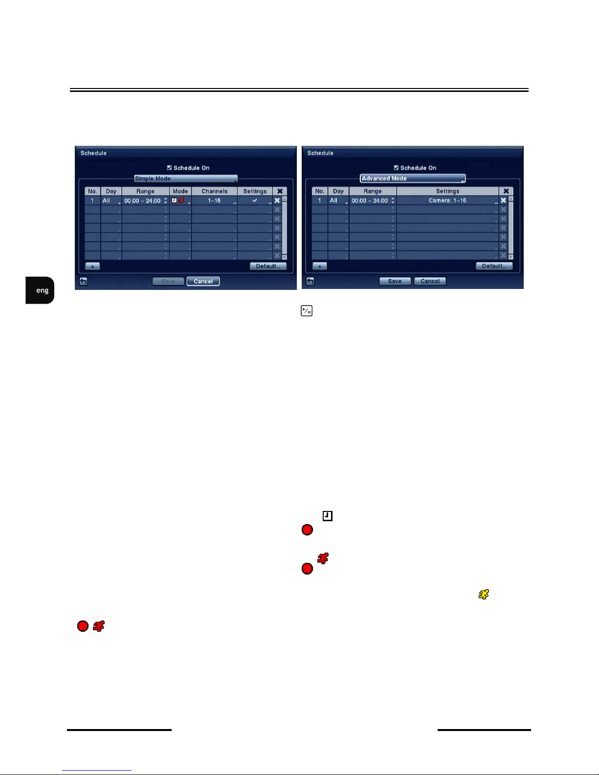
Highlight the Schedule submenu and the following screen will appear:
Highlight the Schedule Mode box and press the button. You can select between Simple Mode
and Advanced Mode. Selecting Advanced Mode allows you to set up individual recording
schedule for each event.
This DVR allows you to create very complex recording schedules in order to adjust recording settings
to the specificity of the object and to save disk space. The Schedule is designed as an easy to read
table. For each option additional settings such as days of the week, recording hours, recording modes,
recording channels, speed and quality may be defined. New points of the Schedule are added with the
help of the + button at the bottom of the table.
DAY position allows for selecting days, when the recording takes place. Sun, Mon, Tue, Wed, Thu,
Fri, Sat, M~F (Mon-Fri), Holiday (holidays, previously set in Date / Time menu) are available.
RANGE allows for setting the recording time for each day, with 15 minutes step increment.
MODE allows for switching between the following recording modes: NO RECORD, TIME,
EVENT, and TIME&EVENT.
NO RECORD should be selected for those time periods when recording is not to be conducted.
If the DVR operates in schedule recording mode, the icon is displayed in the upper left corner of
the picture. Additionally, the device displays the icon next to the aforementioned one, if time
frames for the schedule recording are set.
If the DVR operates in the event recording mode, the icon is displayed in the upper left corner of
the picture. Additionally, the device displays the icon, if the event recording is currently taking
place.
If the DVR operates in the pre-alarm mode, and no alarm events were detected, the icon is
displayed in the upper left corner of the screen. With alarm events detected, the DVR displays
icons instead.
CHANNELS field allows for selecting the channels that will be recorded according to the recording
schedule.
Page 43
NDR-HA4208 / NDR-HA4416 1.2 version - User’s manual
All rights reserved © NOVUS Security Sp. z o.o.
43
RECORDER’S MENU
Widok dla NV-DVR1600
SETTINGS field allows for selecting the recording speed, ranging from 0.1 to 25 fps, and the quality
of the recordings: VERY HIGH, HIGH, STANDARD, LOW.
Selecting the results in deletion of the particular line of schedule.
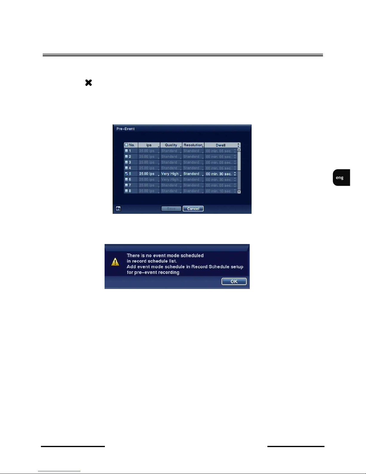
3.4.3 Pre-Event
Highlight the Pre-Event submenu and the following screen will appear:
If event recording wasn’t enabled earlier, a notification window is displayed.
If recording is performed in EVENT mode, a pre-event recording is possible.
IPS field allows for setting the pre-event recording speed, ranging from 0.1 to 25 fps.
Quality field allows for selecting the quality of the recording: VERY HIGH, HIGH, STANDARD,
LOW.
DWELL allows for setting the time of pre-alarm recording, ranging from 5 seconds to 30 minutes.
Attention: If the recorder is active in the Schedule recording or Schedule&Event recording mode,
the pre-alarm settings remain inactive.
Page 44
NDR-HA4208 / NDR-HA4416 1.2 version - User’s manual
All rights reserved © NOVUS Security Sp. z o.o.
44
RECORDER’S MENU
Widok dla NV-DVR1600
3.5. Event
The DVR has the ability to detect various event types. Depending on settings, various actions may be
taken as a result.
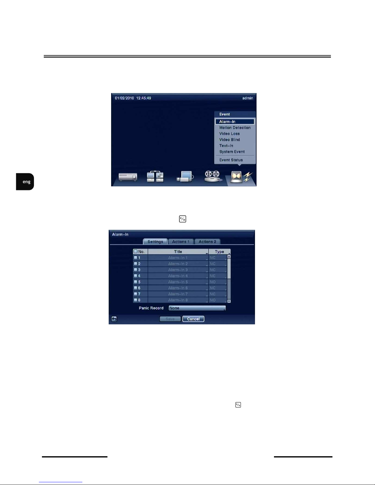
3.5.1. Alarm-in.
Highlight Alarm-In in the Event menu and press button. The Alarm-In setup screen appears.
This submenu allows for enabling or disabling each of the alarm inputs located in the connector block
at the rear of the device. To activate/deactivate particular input please select desired input number in
the NO. column.
Assigning a desired name for the alarm input is possible in TITLE column, using virtual keyboard.
TYPE column allows for defining the operating mode of alarm input. NO - normal open or NC -
normal closed values are selectable.
You can set up the DVR to start panic recording whenever it senses an input on one of its alarm input
connectors. Highlight the box beside Panic Record and press the button. A list of Alarm Inputs
should appear. Please select which alarm input you want to associate with panic recording. The panic
recording is active as long as the alarm input of the device is in its active state, or PANIC button is not
pressed to stop the panic recording.
Page 45
NDR-HA4208 / NDR-HA4416 1.2 version - User’s manual
All rights reserved © NOVUS Security Sp. z o.o.
45
RECORDER’S MENU
Widok dla NV-DVR1600
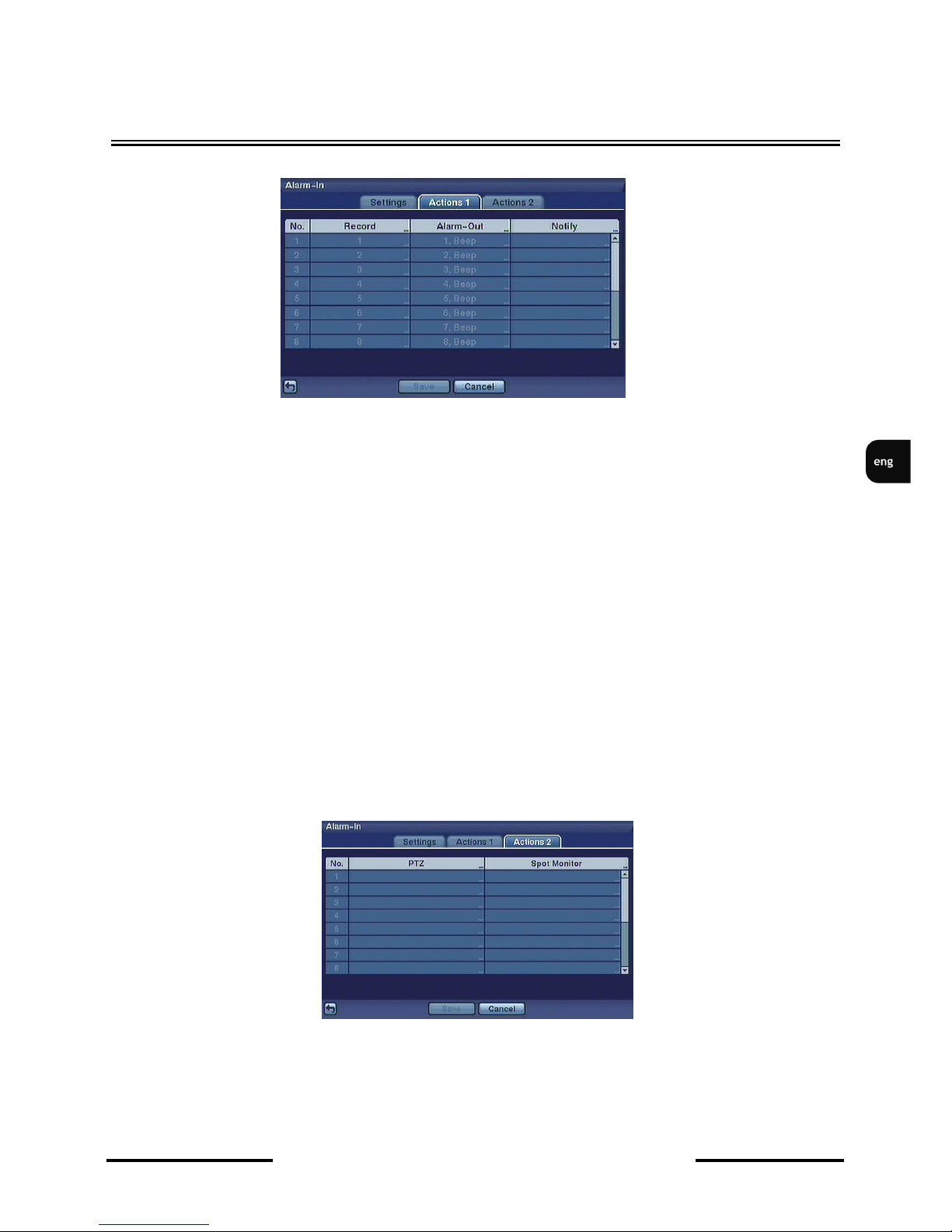
After selecting ACTIONS tab, the following screen appears:
ACTIONS tab allows for setting the response of the DVR after a certain alarm input has been
activated.
RECORD column allows for selecting cameras that will be recording pictures, when a particular alarm
output is activated.
Note: Picture recording depends strictly on the recording mode settings. Selected cameras should
operate in SCHEDULE&EVENT mode.
ALARM-OUT column allows for defining the alarm outputs (or internal buzzer) that are activated
when alarm event occurs.
NOTIFY column allows for defining which functions should be executed when alarm event takes
place:
• E-MAIL - notify by email
• LAN1 ~ LAN5 - connect automatically with desired RASplus software.
• On-screen message - display current state of the DVR on main monitor
Activation of all the above actions is possible through marking the Notify function.
Action2 section allows you to run PTZ camera into one of programmed presets and display it on
selected spot monitor after activation of alarm input.
Note: In order to establish a proper connection between the DVR and remote location please ensure
that the RASplus software is set up properly.
Page 46
NDR-HA4208 / NDR-HA4416 1.2 version - User’s manual
All rights reserved © NOVUS Security Sp. z o.o.
46
RECORDER’S MENU
3.5.2. Motion detection
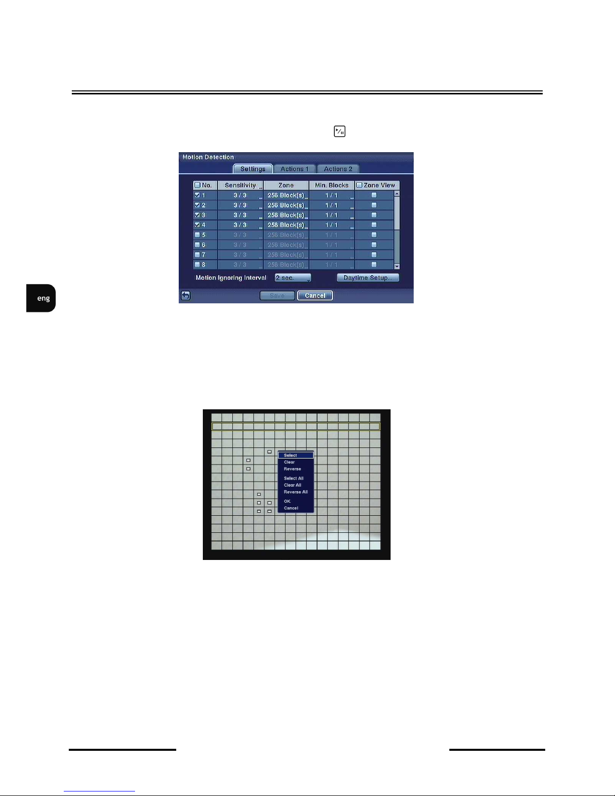
Highlight Motion Detection in the Event menu and press button. The Motion Detection setup
screen appears:
This DVR has built-in video motion detection. NO. column check boxes activate/deactivate motion
detection function for a desired channel.
SENSITIVITY sets the motion detection sensitivity. Level 1 is the minimum sensitivity, level 5 is the
maximum value. Sensitivity is defined separately for day and night operating modes.
ZONE column defines the motion detection zone. Selecting the position displays 24x32 motion
detection grid, as depicted below:
Grid is displayed as superimposed onto the picture from a selected camera.
Attention: You can set up motion zones one block at a time in groups of 8 or 16 individual block
groups (8- and 16-channel DVR respectively). A block group is positioned within the image area using
the Up and Down arrow buttons, and individual blocks within the block groups are selected or cleared
using the camera buttons. A white square over an individual block denotes that motion detection is
active for this block.
Page 47

NDR-HA4208 / NDR-HA4416 1.2 version - User’s manual
All rights reserved © NOVUS Security Sp. z o.o.
47
RECORDER’S MENU
Widok dla NV-DVR1600
Press button to display the menu screen. The menu on the setup screen has the following functions
• SELECT– selects all cells in the field,
• CLEAR - clears all cells in the field,
• REVERSE - reverses current assignment of cells in the field,
• SELECT ALL - selects all cells in the grid,
• CLEAR ALL - deselects all cells in the grid,
• REVERSE ALL- reverses current assignment of cells in the grid
• OK - saves changes and exits the menu
• CANCEL– quits the menu without saving.
MIN. BLOCKS column defines the minimum number of cells that will trigger the motion detection,
when the function is active. This feature allows for setting the cells in such a way, that false alarms
originating from small objects as birds, leaves can be avoided. Sensitivity threshold is defined
separately for night and day.
ZONE VIEW allows for selecting, whether the rectangles in motion detection zones should be
displayed or not.
MOTION IGNORING INTERVAL defines the time of motion insensitivity, that is triggered after a
motion detection event.
DAYTIME SETUP sets the daytime period for the device with the rest of the day treated as night time.
ACTIONS tab is identical in content as the ACTIONS tab in the ALARM IN submenu.
3.5.3. Video loss
Highlight Video Loss in the Event menu and press button. The Video Loss setup screen appears.
Highlight Video Loss in the Event menu and press the button. The Video Loss setup screen
appears.
Highlighting the box under the Video Loss Interval header allows you to set the duration of a signal loss
before the DVR will report a Video Loss. The DVR will not consider any signal loss from a camera to be a
Video Loss if the detected signal loss is shorter than the interval set on this screen.
Highlight Use Ignoring Time and press the button to toggle between On and Off. When set to On, the
DVR will ignore video loss events occurring during the preset period. Highlighting Time Setup and
pressing the button allows you to set up event ignoring time.
Page 48
NDR-HA4208 / NDR-HA4416 1.2 version - User’s manual
All rights reserved © NOVUS Security Sp. z o.o.
48
RECORDER’S MENU
Widok dla NV-DVR1600
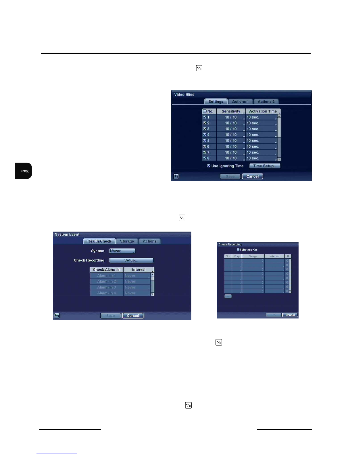
3.5.4. Video Blind
Highlight Video Blind in the Event menu and press the button. The Video Blind setup screen
appears. The DVR checks for picture obscuration.
Highlighting the box under the Sensitivity
heading allows you to adjust the DVR’s
sensitivity to video blind for Black and White
independently from 0 (Never) and 1 (least
sensitive) to 15 (most sensitive).
Settings in the Actions tabs are identical with
those in the Actions tab in the Alarm-in
submenu
3.5.5. System event
Highlight System Event in the Event menu and press button. The System Event setup screen
appears.
DVR can be configured to run self-diagnostics and report the results.
In Health column, particular elements of the system subject to automatic self-diagnostics are
enumerated. Highlight the box under Interval heading, and press button. List of intervals ranging
from 1 hr to 30 days or Never appears. You can select the interval that you want DVR to run selfdiagnostics. When Never option is selected, the self-diagnostics function becomes inactive.
In Recorder function Good means that for a defined period of time images were recorded. Bad means
that for a defined period of time images were not recorded. In alarm-in function Good means that for
a defined period of time an alarm occurred. Bad means that for a defined period of time an alarm didn’t
occur. In Interval column you define a period of time ranging from 1 hour to 30 days, when system
auto diagnostics takes place. If you highlight Never auto diagnostics is switched off.
Highlight the box beside Disk Bad Notify, and press button. Select percentage level of bad disk
sectors at which you want DVR to trigger an alert.
Page 49
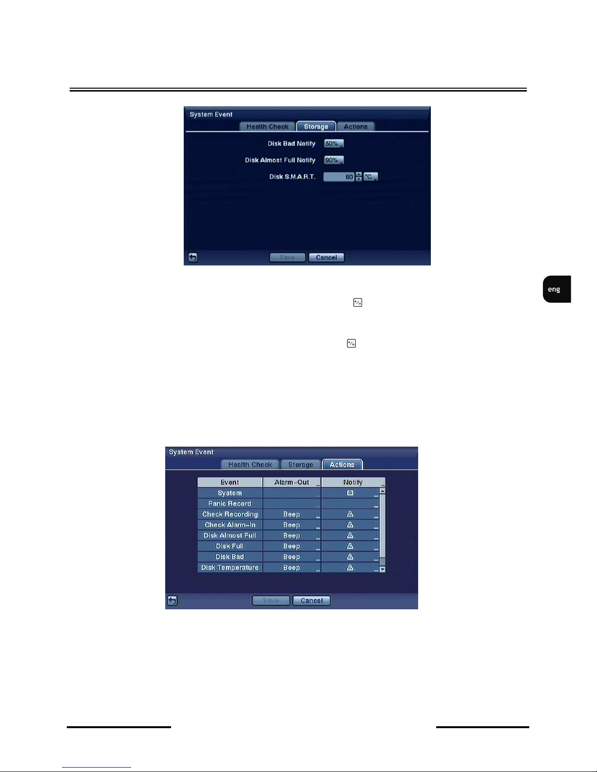
NDR-HA4208 / NDR-HA4416 1.2 version - User’s manual
All rights reserved © NOVUS Security Sp. z o.o.
49
RECORDER’S MENU
Highlight the box beside Disk Almost Full Notify, and press the button. Select the percentage level
of disk usage at which you want the DVR to trigger an alert. Percentage levels range from 80% to 99%.
Highlight the first box beside Disk S.M.A.R.T., and press the button. Use the Up and Down arrow
buttons to scroll through the numbers. Refer to the hard disk drive manufacturer’s documentation for
the correct temperature setting. If the temperature of hard disk drive exceeds the defined threshold, the
system triggers an alert.
After selecting ACTIONS tab, the following screen appears:
For such system events as: SYSTEM, PANIC RECORD, CHECK RECORDING, CHECK ALARM
-IN, DISK ALMOST FULL, DISK FULL, DISK BAD, DISK TEMPERATURE, DISK S.M.A.R.T.,
FAN ERROR pre-defining alarms and system notifying messages is performed identically as in
ACTIONS tab in the ALARM IN submenu. SYSTEM field allows only for e-mail notification, while
PANIC RECORD has its alarm output activation disabled.
Page 50

NDR-HA4208 / NDR-HA4416 1.2 version - User’s manual
All rights reserved © NOVUS Security Sp. z o.o.
50
RECORDER’S OPERATION
Widok dla NV-DVR1600
4. MULTIPLEXER’S OPERATION
4.1. Live monitoring
After finishing the system initialisation, live pictures from camera are displayed on the main monitor,
together with audio feed via speakers. Simultaneous display of all camera inputs is the default mode
(16 or 8, depending on the DVR model). Press one of camera buttons to display particular camera full
screen. Pressing DISPLAY button cycles DVR through the different display formats.
Press SEQUENCE button to start sequential camera display. Pressing this button while in split screen
mode will cause the DVR to go through predefined screen layouts (Full Sequence) or to display live
cameras sequentially in the bottom right corner of the screen (Cameo Sequence).
Press Left or Right arrow buttons to go to the previous or next page.
If images from 4 cameras are displayed simultaneously on the monitor, press Left or the Right button to
change displayed cameras according to the following scheme:
< Full Sequence >
< Cameo Sequence >
If all 4 cameras that should be displayed on the screen are disconnected, their signal is lost, or they
operate in covert mode and user does not have rights to watch pictures from them, such screens will be
excluded from the sequence.
The choice between full-screen sequence or multiple-camera sequence is done via the menu of the
DVR.
Press Freeze button to freeze the currently displayed image subsequent pressing deactivates the
function. When the Freeze function is active, an icon appears in the lower left corner of the screen.
Page 51

NDR-HA4208 / NDR-HA4416 1.2 version - User’s manual
All rights reserved © NOVUS Security Sp. z o.o.
51
RECORDER’S OPERATION
Widok dla NV-DVR1600
4.2. Active Cameo Mode
You can enter the Active Cameo mode by pressing MENU button during any split-screen display
mode. Yellow outline surrounding the video frame indicates active cameo. Pressing arrow buttons
moves active cameo. Press MENU button to exit Active Cameo mode. Cameo mode will deactivate
itself after 15s of user’s inactivity.
In active cameo mode, press the numeric button for the camera you want to display as active cameo
(with the yellow outline). After setting the camera number to active cameo, the DVR moves the active
cameo to the next cameo. You can change the screen layout this way.
Attention: Single camera can be displayed only once within a single screen,
4.3. PIP Mode
You can display a Picture-in-Picture by pressing DISPLAY button. You can change the location of
PIP counterclockwise and clockwise by pressing the Up and Down arrow buttons and change its size
by pressing left/right arrow buttons.
4.4. Zoom Mode
You can enlarge an area of the video by pressing the ZOOM button. For a few seconds after pressing
the ZOOM button, a PIP window is displayed. Inside PIP window, a rectangle shows a zoomed in
area. You can move the rectangle around using the arrow buttons. Subsequent ZOOM button pressing
exits the zoom function. When ZOOM function is turned on, the icon is displayed in the lower left
corner of the screen (if menu settings allow for such action).
4.5. PTZ Mode
After logging in, user with the PTZ control privileges can control PTZ cameras using DVR front panel
buttons. After pressing the PTZ button, selecting the PTZ camera and entering remote control mode is
possible. Second pressing of the PTZ button exits the PTZ control mode.
Once the PTZ button is pressed, cameras defined as PTZ will be shown on the screen. Select the PTZ
camera you wish to control from the menu with the help of Up and Down arrow buttons. icon is
displayed on the screen afterwards.
Use the front panel buttons, press the Left and Right arrow buttons to pan left and right. Press the Up
and Down arrow buttons to tilt the camera up and down. Press button to zoom in, and press
button to zoom out. You can use and buttons to focus the image.
Page 52
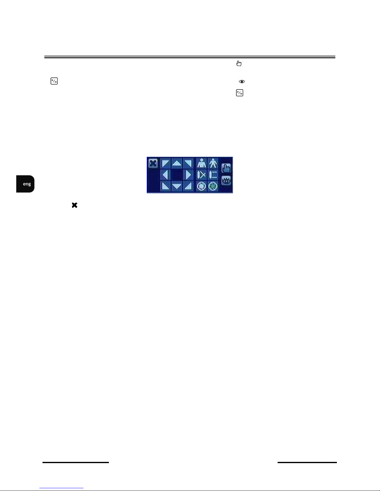
NDR-HA4208 / NDR-HA4416 1.2 version - User’s manual
All rights reserved © NOVUS Security Sp. z o.o.
52
RECORDER’S OPERATION
To program a preset, direct the camera at a selected scene and press .
When the PTZ dialog box appears, select the number you want assign the preset to and press the
button. Use virtual keyboard to enter the preset name. Press button to load PTZ preset and
Preset View dialog box will appear. Select desired preset and press button to load preset.
Pressing MENU button displays PTZ menu. Set feature you wish to control by selecting it from the
menu. Refer to the camera manufacturer’s instructions for proper settings. Depending on camera
specifications, some features may be not supported.
You can use an USB mouse for convenience. Positioning mouse pointer at the bottom of the screen,
displays the following PTZ toolbar:
Clicking on the left side exits the toolbar. Change the toolbar location by clicking the empty space
on the left side of the toolbar and drag it to a desired location
4.6. Image adjustment
Prior to the image parameters setting, please adjust the image settings of monitor and the camera (focus
and white balance).
If a user has privileges to set image settings, pressing and holding a desired camera button for a few
seconds displays the image adjustment box.
User may adjust image settings using the sliders, with values ranging from 0 to 256.
• BRIGHTNESS
• CONTRAST
• HUE
• SATURATION
Note: Changes made affect both live and recorded picture. Image adjustment is active only for the
channels with active video feed.
Page 53

NDR-HA4208 / NDR-HA4416 1.2 version - User’s manual
All rights reserved © NOVUS Security Sp. z o.o.
53
RECORDER’S OPERATION
Widok dla NV-DVR1600
4.7. Event monitoring
If EVENT MONITORING ON is checked in the MAIN MONITOR tab, the picture from a selected
camera will be displayed on the main monitor.
The display mode depends on the amount of cameras linked to the event, and on the number of events
that are simultaneously taking place in the system.
If a single camera is associated with the events, the picture from it is displayed in full-screen. If events
are linked with 2~4 cameras, the cameras participating in that event are displayed in quad mode.
If five to nine cameras are associated with the event, DVR displays the cameras on a 3x3 screen. If 10
or more cameras are associated with the event, DVR displays the cameras on a 4x4 screen.
The display time matches the predefined time of panic recording. After the panic recording times out,
the monitor returns to its previous display mode. In order to return to previous display mode before
event monitoring times out, please press the DISPLAY button or any camera selection button.
4.8. Covert cameras
If the cameras were defined as COVERT 1, the picture from them isn’t displayed unless the user has
the appropriate privileges to watch covert cameras. For COVERT 1 cameras, both the camera name
and status icons are displayed.
If the cameras were defined as COVERT 2, they aren’t displayed unless the user has the appropriate
privileges to watch covert cameras. For COVERT 2 cameras, only the camera name is displayed.
4.9. Spot monitor
You can select the camera you want to display on a Spot Monitor. Press SPOT button on the front
panel or remote control, and select Spot Monitor. Then, select the camera to be displayed on the Spot
Monitor.
If you want to display more than one camera on a Spot Monitor, you can display them sequentially. In
Spot Monitor selection mode, press SPOT button on the front panel and select Sequence On from
the menu to start displaying cameras sequentially. Any cameras that are Off, have lost their video or are
set to Covert (unless the user has authority to view covert cameras) will be excluded from the sequence.
Sequence dwell time is defined in DVR menu.
Page 54
NDR-HA4208 / NDR-HA4416 1.2 version - User’s manual
All rights reserved © NOVUS Security Sp. z o.o.
54
RECORDER’S OPERATION
Widok dla NV-DVR1600
4.10. Recording video
Maximum recording speed of images in 360 x 288 resolution (PAL) is 400(200) images / s. for the
complete system.
Maximum recording speed of images in 720 x 288 resolution (PAL) is 200(100) images / s. for the
complete system.
Maximum recording speed of images in 720 x 576 resolution (PAL) is 100(50) images / s. for the
complete system.
NOTE: If DVR is working in playback mode recording speed may decrease.
NOTE: If DVR is not working in the recycle mode and available disk space becomes exhausted,
hold-up recording is not executed.
4.11. Recording audio
If a DVR is set-up properly, audio recording may be performed from up to 4 channels. If the recording
speed is less than 1 fps, the sound won’t be recorded.
Note: Please check if audio recording is in accordance with your legal regulations.
4.12. Playing recorded video
Users, that have the privileges to watch stored recordings, after logging in to the DVR may do so. To
start the playback, please press the PLAYBACK button. If the stored material is viewed for the first
time since the device power-up, latest recordings will be shown. If the playback mode is entered for the
next time, playback will resume at the point of its last interruption.
NOTE: Only administrator and users with Covert Camera View authority can view video from covert
cameras. Covert cameras in the playback mode are determined by the current camera setting.
PLAY/PAUSE - Press PLAY/PAUSE button to freeze the video on the screen (pause)
Pressing the button plays the recordings backwards. Subsequent pressing of the button changes
the speed of playback. Speed is indicated by the , and icons, that are displayed on the
screen.
Pressing the button plays the recording forward. Subsequent pressing of the button changes the
speed of playback. Speed is indicated by the , and icons.
Pressing the button while in pause mode, moves the picture one frame forward.
Pressing the button while in pause mode, moves the picture one frame backward.
◄
►
Page 55

NDR-HA4208 / NDR-HA4416 1.2 version - User’s manual
All rights reserved © NOVUS Security Sp. z o.o.
55
RECORDER’S OPERATION
PLAYBACK - Press PLAYBACK button in the Playback mode to return DVR to the Live Monitoring
mode. Press SEARCH/STOP button in Live Monitoring mode to return DVR to the Search mode.
CAMERA BUTTONS- Press camera button to display that camera full screen.
DISPLAY - Press DISPLAY button to cycle the display through different screen layouts. The display
modes are: full, 4x4, PIP, 3x3 and 2x2 (not all formats are available for the 8-channel DVR).
ZOOM - Press ZOOM button to zoom the current play back image on the screen.
4.13. Searching video
Selecting (Search) in the Search menu displays the following menu:
• Event log search... - search for recordings associated with events;
• Record Table Search: search for recordings using a recording table with 1 minute step.
• Calendar Search: Selecting Calendar Search searches using a calendar.
• Motion Search: Selecting Motion Search searches for motion events.
• Text-In Search: Selecting Text-In Search searches for text input strings.
4.13.2. Calendar search
Once the Calendar search option is selected, the following menu appears:
Page 56
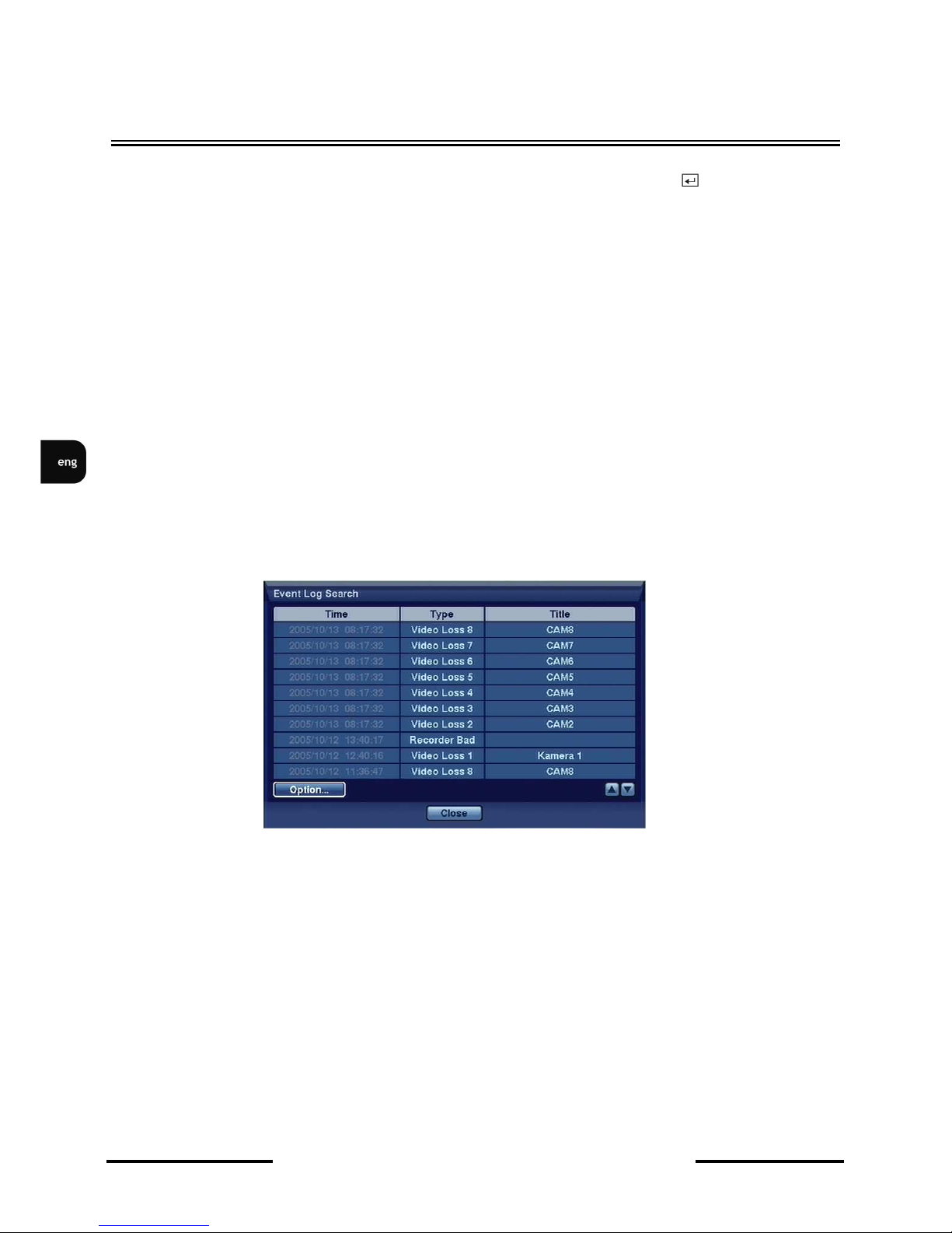
NDR-HA4208 / NDR-HA4416 1.2 version - User’s manual
All rights reserved © NOVUS Security Sp. z o.o.
56
RECORDER’S OPERATION
Days with recorded video display are colored white in the calendar. You can highlight the days with
recorded video using arrow buttons. Once you have highlighted a day, press button to select it.
This will also result in the actualization of video recording origin time on the time bar. Time in which
video was recorded will be highlighted in blue.
NOTE: The time bar is divided into one-hour segments. If a segment is highlighted, it means that
some video was recorded during that hour. However, it does not mean the video was recorded for an
entire hour.
If the DVR’s time and date had been set to an earlier value than the recording’s time, it is possible for
the DVR to have more than one video stream in the same time range. Move to Select a Segment,
and select the video stream you wish to search.
Pressing Enter on the time bar or the Go option results in the DVR switching into playback mode.
NOTE: It is possible that no recorded image displays on the current screen. Press DISPLAY button
and change the screen mode to 4x4. You can find recorded video during target hour easily.
4.13.3. Event log search
Once Event log search option is selected, following screen appears:
All events in the system are recorded in DVR. The Event Log can be accessed by pressing ALARM
button on the front panel of the DVR or with help of playback menu through selecting Event Log
Search option.
There is no determined user authority to display Event Log Search screen, however, the event video
will not be played unless user with Search privileges logs into the system.
NOTE: It is possible that no recorded image displays on the screen despite the search. Press
DISPLAY button and change the screen mode to 4x4. You can then easily find recorded video during
the targeted hour.
You can also narrow your event search by selecting the Option button and setting up the new search
condition.
Page 57
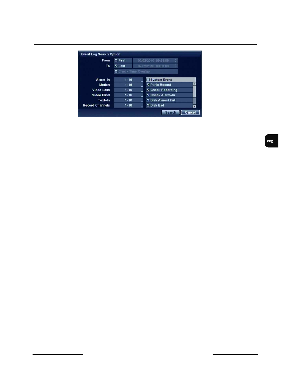
NDR-HA4208 / NDR-HA4416 1.2 version - User’s manual
All rights reserved © NOVUS Security Sp. z o.o.
57
RECORDER’S OPERATION
You can search video from the first to last recorded images, or you can set the start and stop times and
dates. For this last purpose serve the From and To options.
If the DVR’s time and date have been reset to a time that is earlier than some recorded video, it is
possible for the DVR to have more than one video stream in the same time range. Move to Select
a Segment, and select the video stream you want to search..
In case of date/time change, a situation may emerge when two video streams are labelled with the same
date and time. To overcome this, please check the Check Time Overlap in order to include
overlapping fragments in the search. You will only be able to turn the Check Time Overlap on or off
if a user-defined date and time is set in From and To mode. If the DVR’s date and time have been
reset, it is possible for the DVR to have more than one overlapping start and stop time NOTE: a lower
number denotes later recording time.
Highlight the box beside Alarm-In .
You can select the alarm inputs that you want to include in your search.
Highlight the box beside Motion.
You can select the cameras for which you want reports of motion detection.
Highlight the box beside Video Loss.
You can select the cameras for which you want any reports of lost video.
Highlight the box beside Text-In.
You can select the text-in devices for which you want report of text input.
Highlight the box beside Record Channels.
You can select the cameras that you want to search for any reports of event recorded data.
You can also toggle On and Off self-diagnostic events as part of your search. The choices are:
• Panic Record
• Check Recording
• Check Alarm-In
• Disk Almost Full
• Disk Bad
• Disk Temperature
• Disk S.M.A.R.T.
• Fan Error
.
Page 58
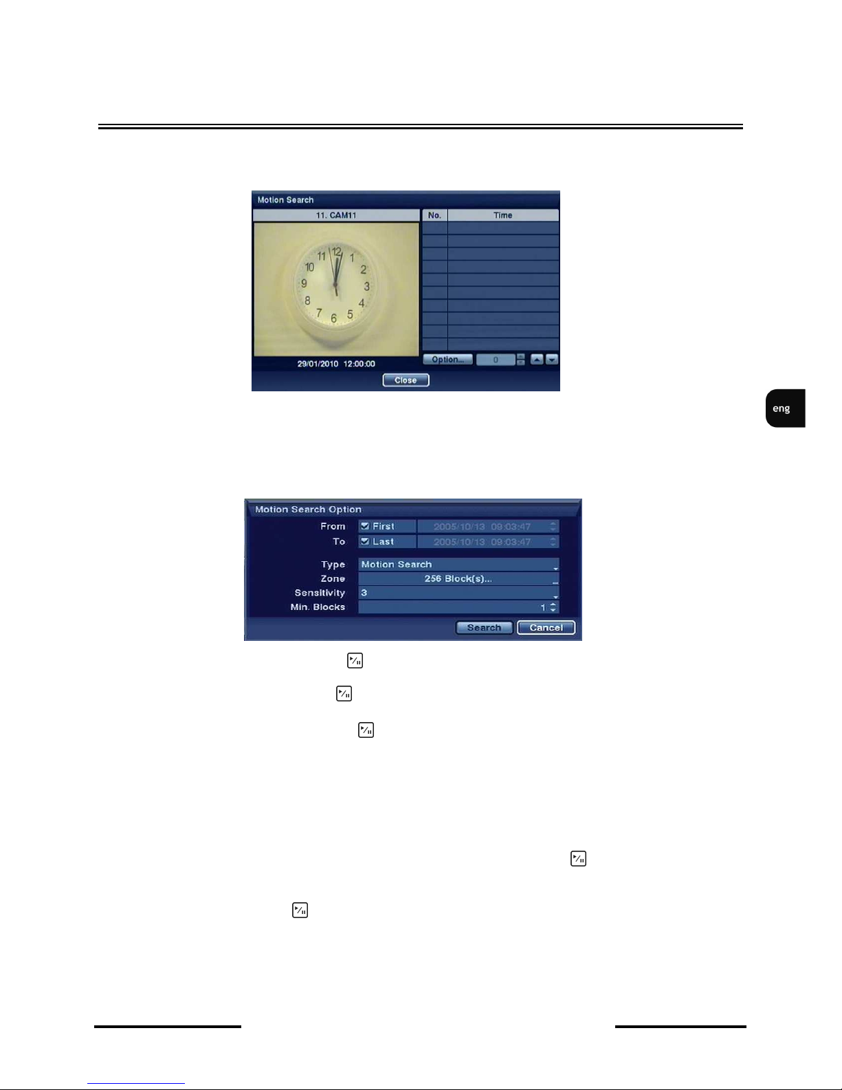
NDR-HA4208 / NDR-HA4416 1.2 version - User’s manual
All rights reserved © NOVUS Security Sp. z o.o.
58
4.13.4 Motion search
Once Event log search option is selected, following screen appears:
The Motion Search can be selected from the Search menu while the DVR displays the camera full screen.
The Motion Search screen displays a list of motion events. Use the arrow buttons to highlight the event for
which you would like to see video
You can also narrow your event search by selecting the Option… button and setting up the new search condition.
Highlight the box beside From and press button to toggle between On and Off. When set to Off, you can
enter a specific Date and Time. When set to On, the search will be from the first recorded image.
Highlight the box beside To and press button to toggle between On and Off. When set to Off, you can
enter a specific Date and Time. When set to On, the search will be from the last recorded image.
Highlight the box beside Type and press button. You can select between Motion Search and Museum
Search. Motion Search detects motion in the defined area. Museum Search detects if a defined object has
moved.
NOTE: Defining the area of the image in which you want to search for motion is nearly identical to setting
up the DVR for Motion Detection.
When setting the Museum Search Zone, the zone should be placed inside of the border line of the target object. If the selected block is placed on the border line, the sensitivity of the Museum Search may decrease.
Once you set your desired search conditions, highlight Search and press button to display the search results in the Event Log screen. Selecting Cancel exits the screen without saving the changes.
Selecting an event and pressing displays the first image of the chosen event. Pressing the Menu button
brings you to full screen playback mode for the chosen event.
RECORDER’S OPERATION
Page 59
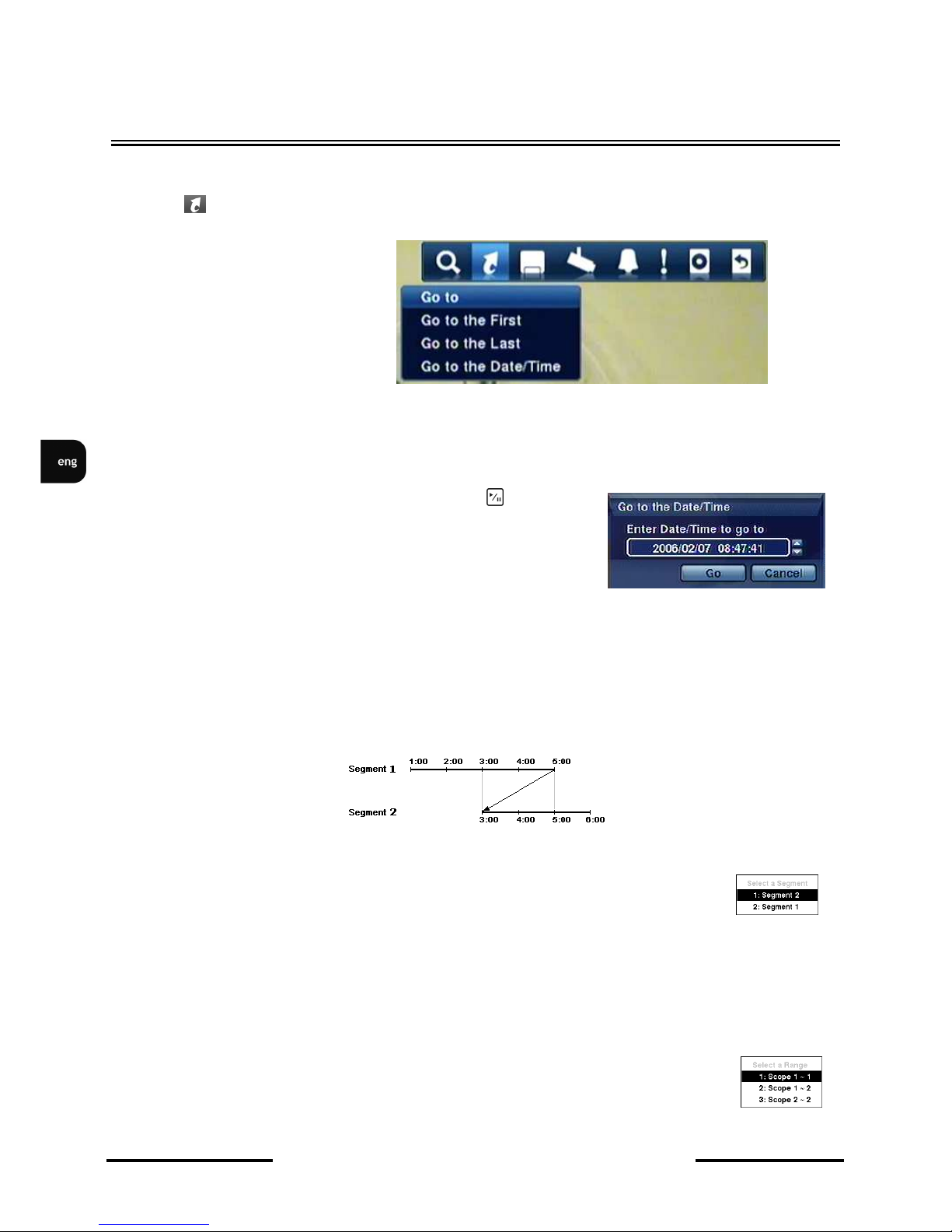
NDR-HA4208 / NDR-HA4416 1.2 version - User’s manual
All rights reserved © NOVUS Security Sp. z o.o.
59
RECORDER’S OPERATION
4.13.1. Go to
Selecting (Go To) in the Search menu displays the following Go to menu.
• Go to the First: Selecting Go to the First displays the first recorded image.
• Go to the Last: Selecting Go to the Last displays the last recorded image.
• Go to the Date/Time: Selecting Go to the Date/Time displays the Go to the Date/Time screen.
If the DVR’s time and date have been reset to a time that is earlier than the existing recorded video, it is
possible for the DVR to have more than one video stream in the same time range. In this case, you can
search overlapping video streams individually by selecting a specific segment. For example, when the
DVR has recorded video from one till five PM and the user changes the time backward from five to
three PM and then continues recording until six PM, there will be two video streams and segments
from three to five PM.
You can search overlapping video streams by selecting a specific time or time range.
If you want to search recorded video at four PM during the overlapping time range
using a search menu such as Go to the Date/Time, select the segment you want to
search
If you want to search recorded video from four to five PM during the overlapping time range using a
search menu such as Event Log Search, Text-In Search or Motion Search, it is possible for the DVR to
have two overlapping start and stop times. You will be asked to select one of the overlapping start and
stop times from the search time ranges as follows:
From four o’clock of the first segment to five o’clock of the first segment
From four o’clock of the first segment to five o’clock of the second segment
From four o’clock of the second segment to five o’clock of the second segment
Move the cursor over the date and time and press the (Play/
Pause) button. You can use the Left and Right arrow buttons to
highlight the year, month, day, hours, minutes and seconds. Use the
Up and Down arrow buttons to change to the date and time you
want to search for video.
Page 60
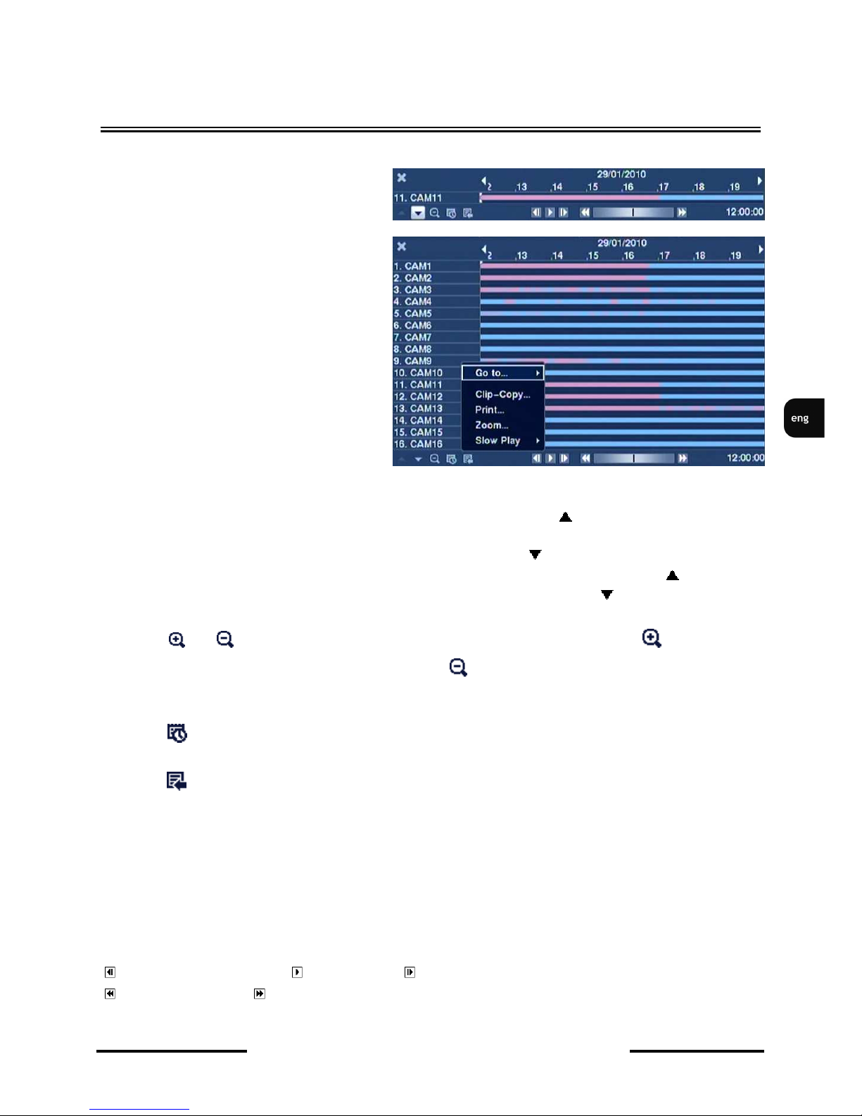
NDR-HA4208 / NDR-HA4416 1.2 version - User’s manual
All rights reserved © NOVUS Security Sp. z o.o.
60
RECORDER’S OPERATION
4.13.1. Record Table Search
Information about recordings are displayed
on the recording status bar. A grey vertical
line indicates the current search position.
To search specific video, move the vertical
line by using the Left or Right arrow
buttons on the front panel or by clicking
the mouse on the desired segment.
If the DVR’s time and date have been
reset to a time earlier than recorded video,
DVR may indicate more than one video
stream in the same time frame. In this
case, the overlapping time range in the
record table will be separated by a yellow
vertical line.
Three viewing modes are available:
Standard, Expanded and Compact view.
Standard view (default) displays combined recording information of all camera channels currently
displayed on the screen. In the Standard view mode, selecting the icon located at the bottom
switches to the Expanded view mode. The Expanded view displays the recording information of each
camera channel currently displayed on the screen. Selecting the icon in the Standard view mode
switches to the Compact view mode which displays only the toolbar. Selecting the icon in the
Compact view mode switches to the Standard view mode, and selecting the icon in the Expanded
view mode switches to the Standard view mode.
Selecting or located at the bottom zooms in the record table. Selecting displays eight
hours of recordings (in 1-minute steps), and selecting displays 24 hours (in 3-minute steps) at once.
To move to earlier or later recordings that are not shown in the current record table screen, select the
arrows located at the end of the time bar by using the arrow buttons on the front panel.
Selecting located at the bottom displays the Calendar Search screen. See the following Calendar
Search section for details.
Selecting located at the bottom displays the Search menu.
Go To: Displays the first or last recorded image, or searches by date and time
Clip-Copy: Clips a video segment and saves it (see the following Clip Copy section for more details).
Print: Prints the current playback image.
Zoom: Zooms the current playback image.
Slow Play: Plays video at low speed (x1/2, x1/3, x1/4, x1/6 and x1/8).
The individual playback controls at the bottom perform the following functions as described below:
Go to the previous image Play/Pause Go to the next image
Fast backward play Fast forward play
Page 61
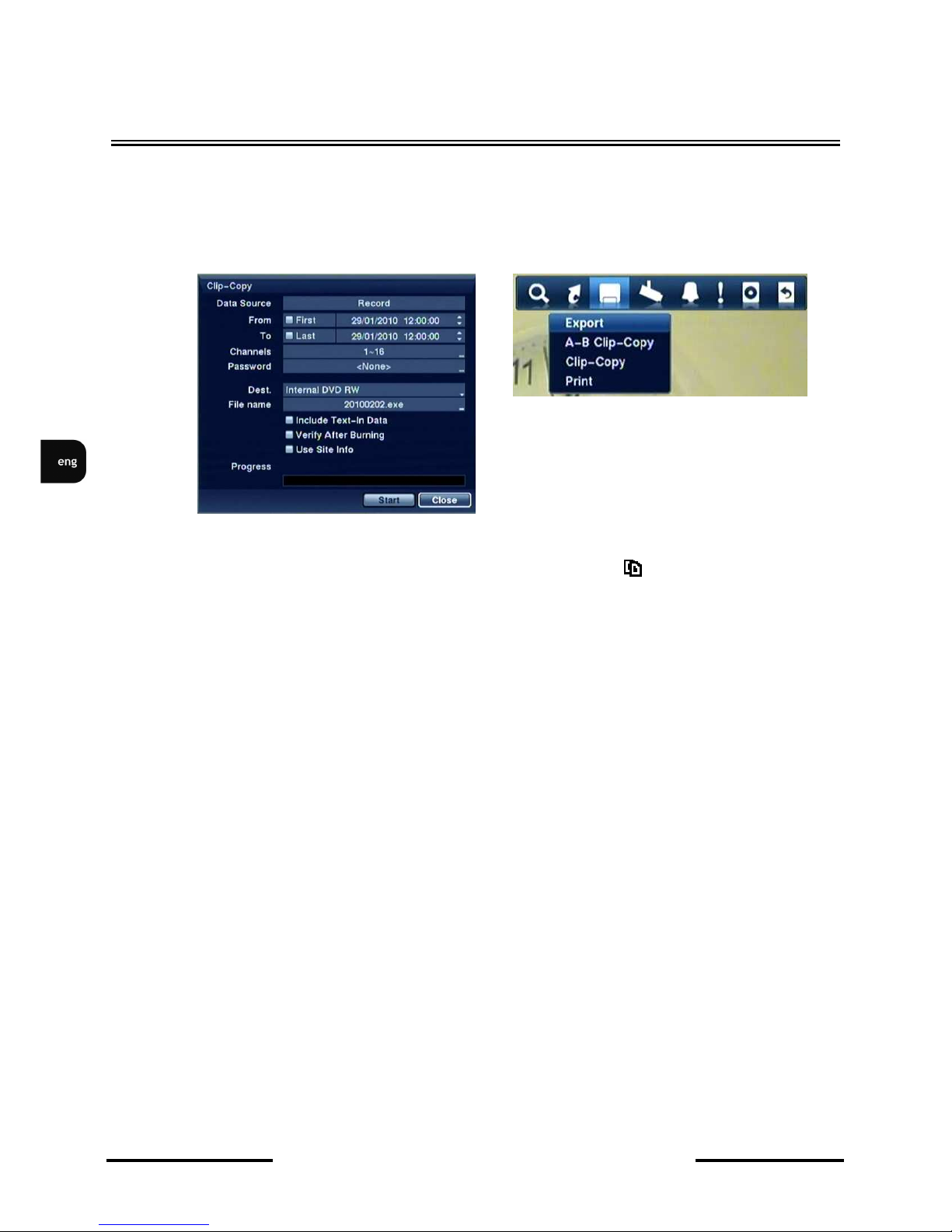
NDR-HA4208 / NDR-HA4416 1.2 version - User’s manual
All rights reserved © NOVUS Security Sp. z o.o.
61
RECORDER’S OPERATION
4.14. Clip Copy
Video clips can be copied on an internal DVD RW drive, or external USB hard disk / flash drive. The
copied video clips can be viewed on computers running Microsoft Windows 98, ME, 2000, XP or
Vista.
Selecting A–B Clip-Copy in the Search – Export menu or pressing the CLIP COPY button during
playback will set the starting point of the video to be clip copied, and the icon displays at the bottom-
left corner of the screen. Selecting A–B Clip-Copy in the Search – Export menu or pressing the CLIP
COPY button again will set the ending point of the video to be clip copied by displaying the ClipCopy screen.
Pressing and holding the CLIP COPY button for more than three seconds while in the Search mode or
Live Monitoring mode initiates the One-Touch Clip Copy function. The last recorded image will be the
ending point of video to be clip copied, and the system will automatically begin to calculate the
possible video data size that the selected storage media can handle.
Select Clip-Copy in the Search – Export menu or press the CLIP COPY button while in the Search
mode or Live Monitoring mode, and the Clip-Copy screen appears to allow clip copy setup.
NOTE:
• The USB device for clip copy must be FAT 16 or FAT32 format
• Partition size should not exceed 32 GB.
• While copying video clips on the CD/DVD-RW, the recording speed might decrease.
• While copying video clips on the CD/DVD-RW, the DVR will stop archiving video data until
clip copy is finished.
The name of the backup file with an .exe extension is created automatically entitled YYYYMMDD.
Pressing ENTER in the FILE NAME field brings up virtual keyboard to enter the filename manually.
To save the file in a specified folder, please add a slash „/” and a directory name e.g. „DIRECTORY/
FILE.EXE”.
Note: Characters such as \ / : ; * ? “ < > | cannot be used in the filename.
Page 62

NDR-HA4208 / NDR-HA4416 1.2 version - User’s manual
All rights reserved © NOVUS Security Sp. z o.o.
62
RECORDER’S OPERATION
When no free space is currently available on the target device, a message informing about lack of free
space will be displayed, together with question if the amount of data copied should match the free
space left on the memory device.
During copy, PROGRESS bar indicates the current completion status of copying process.
An appropriate message is displayed when the copying process finishes.
NOTE: Do not copy video clips larger than 2GB .
You can use other functions on the DVR while video is being backed up. To do this, highlight
the Close button and press button. You can return to the Clip-Copy screen at any time to check
the progress.
NOTE: During Clip Copy, you cannot shut the system down, clear data on the storage device, or
format the storage device.
Note: During clip copy, disconnecting USB cable and/or power supply of the device is forbidden,
as it may cause the DVR to malfunction or damage the external device itself. During
subsequent clip copying, an information on system malfunction may be displayed. In order
to restore the situation to normal, please restart the DVR. When data located on the
external memory devices are damaged, please format the device or use data recovery
software.
Page 63

NDR-HA4208 / NDR-HA4416 1.2 version - User’s manual
All rights reserved © NOVUS Security Sp. z o.o.
63
RECORDER’S OPERATION
4.15. Playback
You do not need to install any special software on your personal computer to review the video clips.
The copied video clip contains the ClipPlayer program.
NOTE: It is suggested that the computer used for the ClipPlayer program has at least a 800MHz
Pentium III. If your CPU is slower than stated above, video clips recorded at maximum speed with very
high image quality will be played back slowly. DirectX 8.0 or higher is required while VGA card with
16MB or higher video RAM is recommended for proper operation.
NOTE: Proper image display depends on the display settings of your PC.
If you are experiencing display problems, click the right mouse button on the background screen and
select Properties à Settings then set the Color quality to “32 bit”.
Page 64

NDR-HA4208 / NDR-HA4416 1.2 version - User’s manual
All rights reserved © NOVUS Security Sp. z o.o.
64
RECORDER’S OPERATION
Next, select the ADVANCED button and TROUBLESHOOTING tab, then select the maximum value
of hardware acceleration.
To check version number of the libraries installed, please enter „dxdiag” in the RUN bar, located in the
START menu, and press ENTER.
In the DISPLAY please select DIRECT DRAW HARDWARE ACCELERATION and check if it’s
working properly.
Please update the video drivers to the newest ones recommended by the producer. When still having
problems with playback, please consider change of the video card. ATI - based video cards are
recommended.
Page 65

NDR-HA4208 / NDR-HA4416 1.2 version - User’s manual
All rights reserved © NOVUS Security Sp. z o.o.
65
RECORDER’S OPERATION
Playback software description:
Pressing X
closes the software.
Pressing moves to the beginning of the recording.
Pressing plays the recording fast backwards.
Pressing moves to a previous frame of the recording.
Pressing plays the recording forward with normal speed.
Pressing moves to the next frame in the recording.
Pressing plays fast forward.
Pressing moves to the end of the video.
Pressing the button in full-screen mode displays previous camera.
Pressing the button allows for
switching between various display modes: 2x2, 3x3 and 4x4.
Pressing the in full screen mode displays the next camera.
By highlighting Image processing you can save images in the form of BMP format, print them or get
file information (cameras, the name of camera input, time, type, size, resolution).
Image processing function (brightness, blurring, sharpness) is not available in split.
Click the to select from Normal, Double and Full Screen views.
Copied materials may be watermarked to prevent manipulation. icon visible in the lower right of
the picture indicates that the material wasn’t altered in any way. icon means that the displayed
image was changed in any way compared to the original.
NOTE: If the VGA card or monitor for your PC does not support 640x480 video resolution, Full
Screen might not display properly when selected. If this happens, press the ESC key on your PC to
return to the normal screen mode.
Placing the mouse cursor on an image and clicking will cause that image to display full frame.
NOTE: Do not run more than one ClipPlayer on a PC, otherwise the ClipPlayer will not operate
properly.
Page 66

NDR-HA4208 / NDR-HA4416 1.2 version - User’s manual
All rights reserved © NOVUS Security Sp. z o.o.
66
PTZ CAMERAS CONTROL AND CONNECTION
5. PTZ CAMERAS CONTROL AND CONNECTION
NDR-HA4208 and NDR-HA4416 are able to control up to 16 cameras through RS-485 port
connected in daisy chain. Daisy chain cannot exceed 1200m total length and 1.5m taps from the main
line.
You can control PTZ cameras, motor-zoom cameras with optical or digital zoom. You can control
cameras from main panel of the DVR, via Internet Explorer or RAS+ software. To control cameras
you have to assign addresses to each camera.
The DVR is able to cooperate with various control protocols, e.g. Novus-C, Novus-C1, Pelco-D and
others.
Note: All the cameras in one system should have the same control protocol and transmission
speed set in their menus (check the user’s manual of the camera for more details).
Presented connection description is dedicated to Novus camera. To connect cameras of different
producent please contact your Novus distributor and read instruction of the camera.
Note: For PTZ cameras control you can also use RS-232 port. In this case you need to use
RS232—RS-485 converter. It is required in case of connection keyboard and PTZ cameras to the DVR
in the same time.
5.1 Novus PTZ cameras connection.
PTZ cameras are connected in daisy chain with UTP5 cable. Cameras are connected to RS-485 port.
Telemetry junctions are located at the rear of the device, as a terminal block. To ease the connecting
process, plugging the socket out of the terminal is possible. Please connect the wires between the DVR
and cameras in a way described below:
For the detail information regarding PTZ settings of the DVR please find in the chapter 3.3.1
PTZ control via front panel buttons please find in the chapter 2.4
+
- connect to Rx + (Tx+) in camera
-
- connect to Rx - (Tx-) in camera
Page 67

NDR-HA4208 / NDR-HA4416 1.2 version - User’s manual
All rights reserved © NOVUS Security Sp. z o.o.
67
PTZ CAMERAS CONTROL AND CONNECTION
Appendix 1:
Novus camera connection
camera Novus CAMA I
nr 1
Vision cord
camera Novus CAMA I
nr 9 (16)
24VAC +
24VAC -
FGND
(RX+)
RX+(TX+)
RX-(TX-)
GND
24VAC-
24VAC+
24VAC +
24VAC -
FGND
(RX+)
RX+(TX+)
RX-(TX-)
GND
24VAC-
24VAC+
UTP 5 max 1200m
max 1,5 m
max 1,5 m
View of NDR-HA4416
Page 68
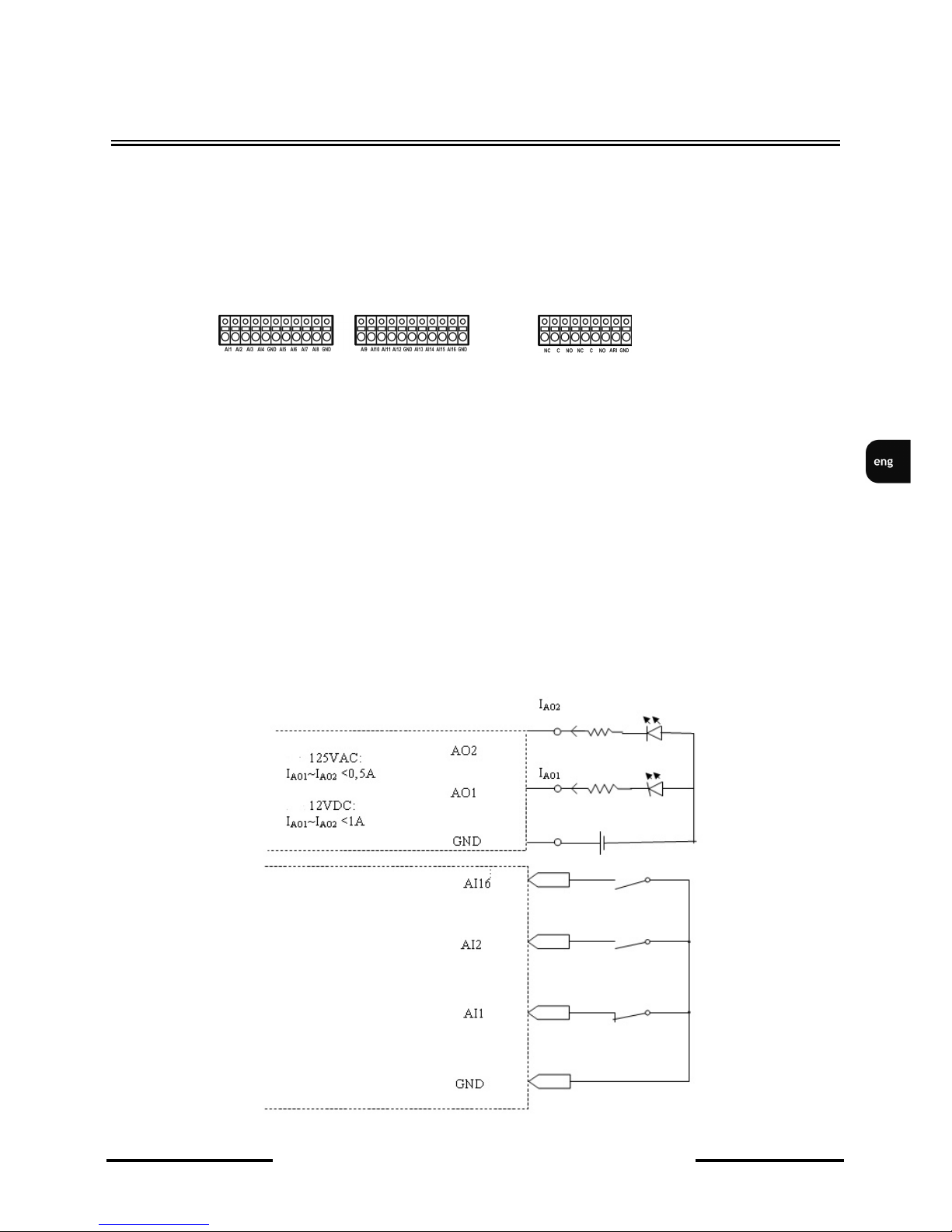
NDR-HA4208 / NDR-HA4416 1.2 version - User’s manual
All rights reserved © NOVUS Security Sp. z o.o.
68
CONNECTING DEVICES TO ALARM INPUTS AND OUTPUTS
6. CONNECTING DEVICES TO ALARM INPUTS AND OUTPUTS
Connecting devices to alarm inputs and outputs.
NDR-HA4208 and NDR-HA4416 recorders feature 8 or 16 alarm inputs and out allowing you to
connect external devices. Wiring connectors are equipped with clamp terminals.
NOTE: Alarm inputs and outputs are not lightning-protected. User should protect the inputs against the
electric discharges, that may damage the equipment..
Current load capacity of each alarm input cannot exceed 2 A for 125 V AC and 1A for 30 VDC .
Directly to outputs you can connect e.g. LED (light-emitting diode) creating a circuit (as presented on
the chart below) for each output. If there is a need to connect devices which demand a lot of current
you have to use additional circuits (e.g. with a transmitter). Outputs can work as normally closed or
normally open.
Alarm inputs/outputs of NDR-HA4416
Page 69
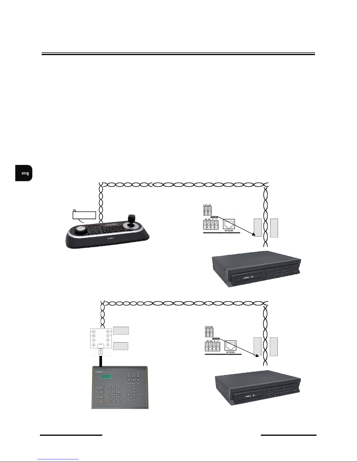
NDR-HA4208 / NDR-HA4416 1.2 version - User’s manual
All rights reserved © NOVUS Security Sp. z o.o.
69
7.
MULTIPLEXER’S OPERATING FROM SYTEM KEYBOARD
NDR-HA4208 and NDR-HA4416 may be remotely controlled using NV-KBD70 keyboard. System is
controlled via RS-485 port located in the device. Controlling large systems is possible in such a
connection (up to 10 DVRs). The RS-485 wire length should not exceed 1200m. In such a system,
devices are cascade connected, with taps length not exceeding 1,5m.
Keyboard has its keys in accordance with appropriate buttons in the DVR, serving the same function.
Additional informative feature is the LCD display located in the keyboard, displaying information
about active functions, transmission parameters etc.
Diagrams depicting connection between NV-KBD70 and NDR-HA4208/16 are shown below. Details
on connections and remote control of the device using keyboard are included in keyboard’s manual.
MULTIPLEXER’S OPERATING FROM THE LEVEL OF NV-
KBD60 SYTEM KEYBOARD
RS485+
RS485-
RS485+
RS485-
PIN 4
RS485(TX+)
PIN 5
DOME 2
NV-KBD70
NV-KBD30
Page 70

NDR-HA4208 / NDR-HA4416 1.2 version - User’s manual
All rights reserved © NOVUS Security Sp. z o.o.
70
MULTIPLEXER’S OPERATING FROM THE LEVEL OF NV-
KBD60 SYTEM KEYBOARD
OBSŁUGA REJESTRATORA Z POZIOMU KLAWIATURY SYSTEMOWEJ NV-KBD60
8. DISPLAYING TEXT ON THE IMAGE
8.1 Displaying text on the image
NDR-HA4208 and NDR-HA4416 feature the possibility of displaying both the images from the
cameras and ASCII text generated by external devices, such as cash registers, ATM machines or a
PC computers with access control software installed. The DVR can support up to 16
peripheral devices that generate text and are connected to LAN, RS-232, RS-485 and USB ports.
Note: Proper communication between peripherals and the DVR requires that the data format sent
by the peripheral is known. As mentioned before, the data should be in ASCII format. In
case devices generate text data in other formats, no text displaying is possible.
The DVR doesn’t limit the amount of recorded text. Text is stored together with images originating
from corresponding cameras.
In order for the transaction to be displayed in the preview and playback modes you need to highlight Transaction in the recorder’s menu found in the Devices / Monitors / OSD submenu.
When operating in network environment, text data are not displayed, both in live and playback
modes. During network copying of the recordings using Minibank format, text data are included
into the file. An example of this is shown below:
In order to enable the function of displaying text on the images you need to choose Transaction
sub-menu in the Event menu.
DISPLAYING TEXT ON THE IMAGE
Page 71

NDR-HA4208 / NDR-HA4416 1.2 version - User’s manual
All rights reserved © NOVUS Security Sp. z o.o.
71
DISPLAYING TEXT ON THE IMAGE
After selecting TEXT-IN, the following screen appears:
NDR-HA4208 and NDR-HA4416 may be programmed in such way that the device starts a desired
action (i.e. starts recording, enables internal buzzer, activates relay outputs, or sends notifying messages) whenever it receives some pre-defined text string.
Caution: In case displaying text on the images is simultaneously done from a few channels it can
slow the system down.
Page 72
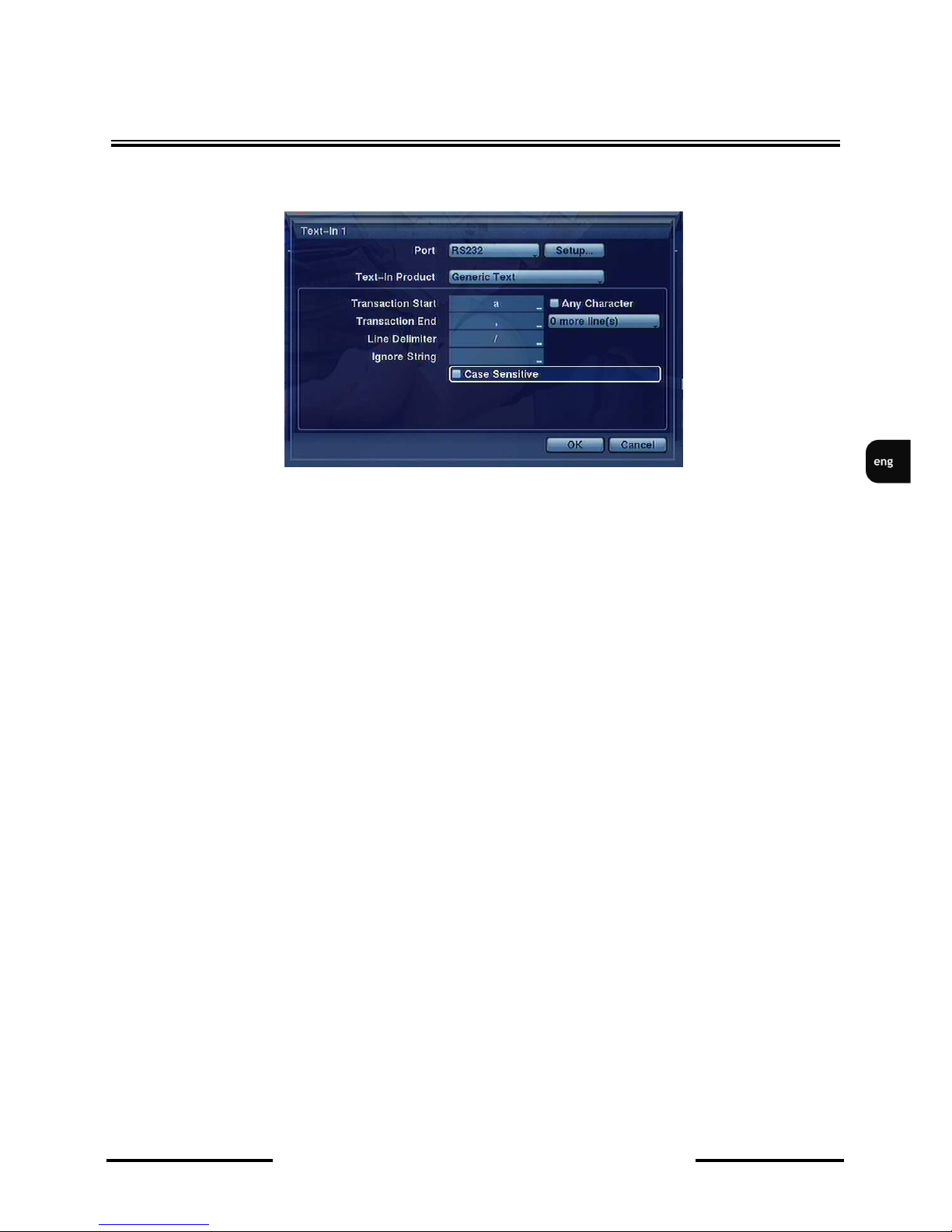
NDR-HA4208 / NDR-HA4416 1.2 version - User’s manual
All rights reserved © NOVUS Security Sp. z o.o.
72
DISPLAYING TEXT ON THE IMAGE
After highlighting Settings the below tab appears on the screen:
PORT position allows for defining the input the text data are sent to. RS-485, RS-232 or one of
four USB inputs are selectable.
Note: If no PORT is defined, the rest of fields are left inactive.
When working with cash registers or
recorder
s you need to set the Settings according to their pro-
ducers’ recommendation.
When cooperating with cash registers, etc. please adjust the transmission parameters in SETUP, as
required. Please define (using virtual keyboard) the characters, that will be interpreted as start of the
text input, in the TRANSACTION START field. Please set the starting character in accordance
with the peripheral’s manufacturer specification.
In case transaction starts with a different character each time, please check the ANY CHARACTER
option. TRANSACTION START field is disabled, as a result.
In the TRANSACTION END field, please define (using virtual keyboard) the characters, that will
be interpreted as ending of the text input. Please set the ending character in accordance with the peripheral’s manufacturer specification..
LINE DELIMITER allows for defining the characters that will be interpreted as end of the line, for
purpose of text formatting.
X MORE LINES allows for setting the number of additional lines (ranging 0~10) the DVR stores
in the process.
IGNORE STRING allows for setting the characters the DVR ignores during text capture.
When case sensitivity is needed, please check CASE SENSITIVE option.
TIMEOUT position allows for setting the maximum interval between text messages (ranging 5
s~15 min) after which the TIME OUT message is displayed, informing about data transmission
ending.
Page 73
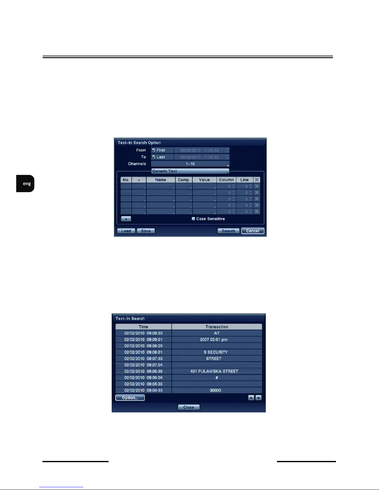
NDR-HA4208 / NDR-HA4416 1.2 version - User’s manual
All rights reserved © NOVUS Security Sp. z o.o.
73
DISPLAYING TEXT ON THE IMAGE
In the Ignore position you define strings, whose detection is totally ignored by the system.
If there are both small and capital letters of different characteristic in the system you need to tick off
Case Sensitive.
8.2 Transaction search
The
recorder
saves text generated by connected peripheral devices in the data-base register. If you
want to set Transaction Search you need to highlight Option. The following screen appears:
FROM - TO and CHANNELS fields define the time frame and channels that are searched for the
text presence. Next, please define the keywords that are searched for in the registry. Logical “AND”
and “OR” operators are available in the search. Search may be conducted also using 5 keywords
simultaneously. CASE SENSITIVE search takes case sensitivity into account. Comp. Value, Col-
umn, Line don’t require filling in, and cooperate only with specialized cash registers.
After selecting SEARCH and pressing ENTER a search screen is displayed:
Page 74

NDR-HA4208 / NDR-HA4416 1.2 version - User’s manual
All rights reserved © NOVUS Security Sp. z o.o.
74
DISPLAYING TEXT ON THE IMAGE
After choosing a required result and choosing the first image of a registered transaction with an
associated keyword is displayed. By choosing you can start playback of the registered material
connected with the transaction. By choosing PLAYBACK you switch to Live Monitoring.
Caution: in case of images played back on the screen you need to choose 4x4 display mode in order to quickly find recorded images.
Caution: Text information will be displayed on the image only in case of their playback at a standard speed x1 and in the full screen view!!!
Page 75
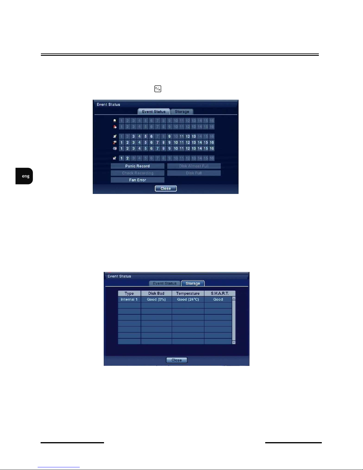
NDR-HA4208 / NDR-HA4416 1.2 version - User’s manual
All rights reserved © NOVUS Security Sp. z o.o.
75
9. SYSTEM STATUS
Highlight Show Event Status and press button to display the Event Status screen:
The Event Status window contains information about the current status of the DVR, together with the
status of its inputs. Events or associated channels will blink in yellow in case of event detection.
ALARMY IN., MOTION, VIDEO LOSS, TEXT-IN are enabled depending on the settings present in
the EVENT menu.
Alarm-In Bad and Recorder Bad will be highlighted when each event is detected based on the
settings you made in the System Event setup screen in the Event menu.
DISK FULL is active, when the DVR has the „recycle” function disabled, and all of the disk space has
been used.
Selecting STORAGE tab displays information about the disk currently installed in the DVR, such as
the percentage of bad sectors, temperature and overall disk status, using S.M.A.R.T. (Self-Monitoring
Analysis and Reporting System).
DISPLAYING TEXT ON THE IMAGE
Page 76
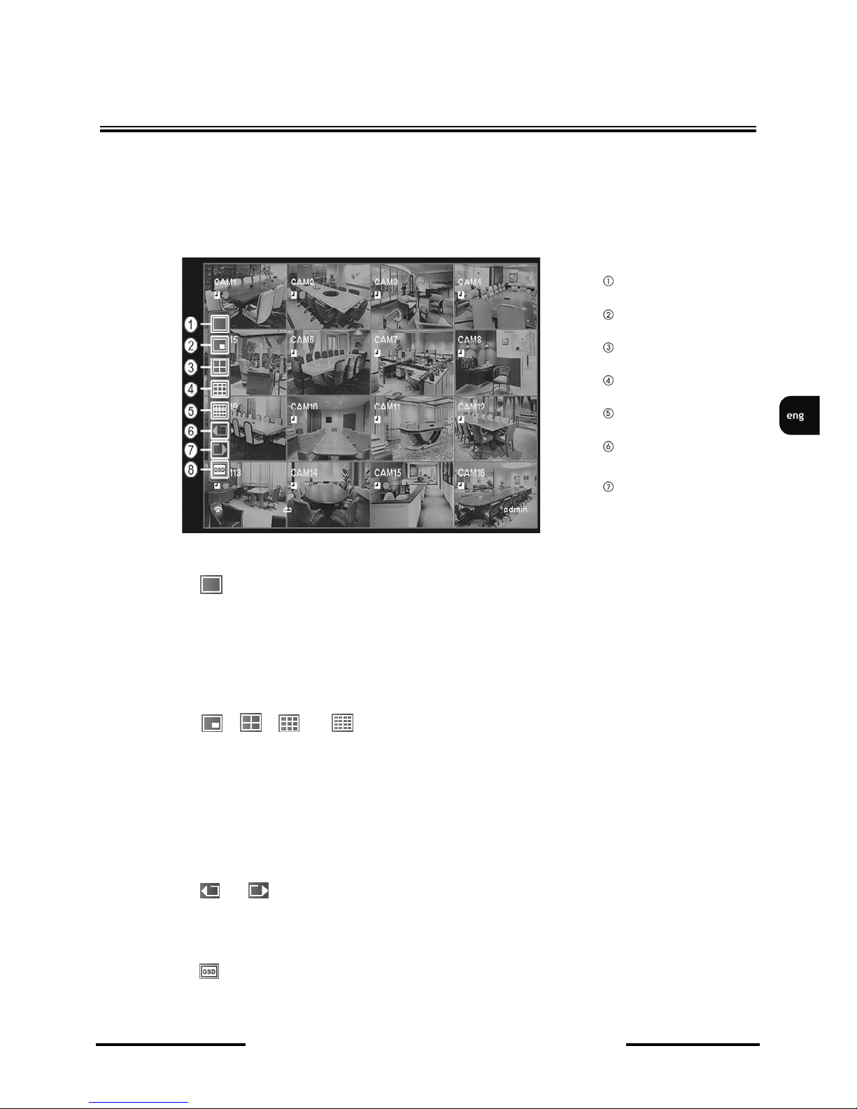
NDR-HA4208 / NDR-HA4416 1.2 version - User’s manual
All rights reserved © NOVUS Security Sp. z o.o.
76
10. USING A MOUSE
You can use a mouse instead of the front panel buttons to perform many of the DVR functions. In the
Live Monitoring mode or Search mode, moving the mouse pointer to the left edge of the screen displays
the following Mouse Display menu.
Full Screen
Selecting (Full Screen) in the Mouse Display menu and choosing the camera number button displays the selected camera full screen. It is the same as pressing the individual camera buttons on the
front panel or clicking the left mouse button on a camera image when in one of the multiview formats
(i.e., 2x2, 3x3 or 4x4). Clicking the left mouse button on the screen again returns to the previous display mode.
PIP, 2x2, 3x3, 4x4
Selecting , , or (PIP, 2x2, 3x3 or 4x4) in the Mouse Display menu displays the
cameras in the selected multiview screen mode (PIP, 2x2, 3x3 or 4x4). Selecting each display mode
is the same as pressing the DISPLAY button or scrolling the mouse wheel up and down when in one
of the multiview formats (i.e., 2x2, 3x3 or 4x4).
Previous Group, Next Group
Selecting or (Previous Group or Next Group) in the Mouse Display menu moves to the previous or next page. It is the same as pressing the GROUP button.
OSD
Selecting (OSD) in the Mouse Display menu toggles OSD On and Off.
NOTE: The PIP display mode will not be supported in the search mode.
DISPLAYING TEXT ON THE IMAGE
Full Screen
PIP
2x2
3x3
4x4
Previous Group
Next Group
Page 77

NDR-HA4208 / NDR-HA4416 1.2 version - User’s manual
All rights reserved © NOVUS Security Sp. z o.o.
77
NOTES
Page 78

NDR-HA4208 / NDR-HA4416 1.2 version - User’s manual
All rights reserved © NOVUS Security Sp. z o.o.
78
NOTES
Page 79

NDR-HA4208 / NDR-HA4416 1.2 version - User’s manual
All rights reserved © NOVUS Security Sp. z o.o.
79
NOTES
Page 80

NDR-HA4208 / NDR-HA4416 1.2 version - User’s manual
All rights reserved © NOVUS Security Sp. z o.o.
80
2010-10-18
AAT Holding sp. z o.o., 431 Pulawska St., 02-801 Warsaw, Poland
tel.: +4822 546 07 00, fax: +4822 546 07 59
www.novuscctv.com
Page 81
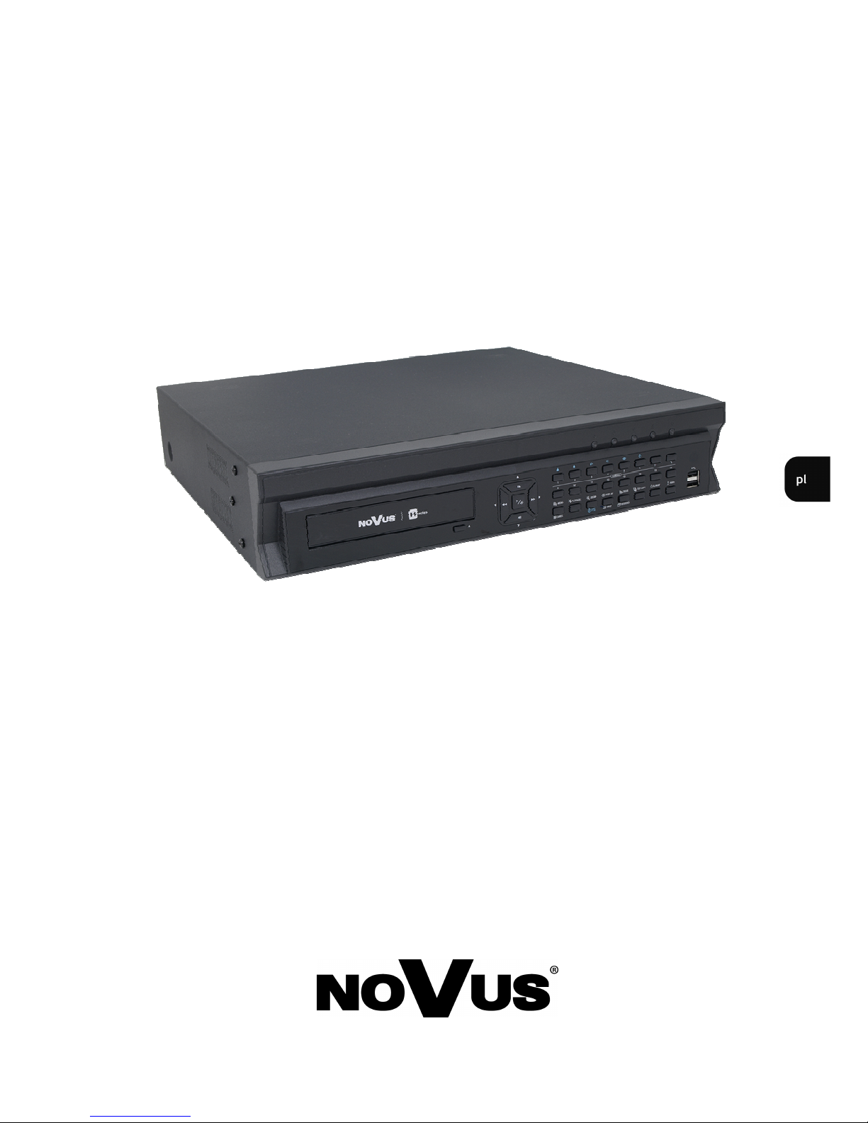
NDR-HA4208
NDR-HA4416
i n str u k c j a obs ł u g i
Page 82

NDR-HA4208, NDR-HA4416 - Instrukcja obsługi wer. 1.2
Wszelkie prawa zastrzeżone © NOVUS Security Sp. z o.o.
2
Dyrektywy EMC (2004/108/EC) i LVD (2006/95/EC)
Oznakowanie CE
Nasze produkty spełniają wymagania zawarte w dyrektywach oraz przepisach krajowych
wprowadzających dyrektywy: Kompatybilność elektromagnetyczna EMC 2004/108/EC.
Niskonapięciowa LVD 2006/95/EC. Dyrektywa ma zastosowanie do sprzętu elektrycznego
przeznaczonego do użytkowania przy napięciu nominalnym od 50VAC do 1000VAC oraz od 75VDC do
1500VDC.
Dyrektywa WEEE 2002/96/EC
Informacja dla użytkowników o pozbywaniu się urządzeń elektrycznych i elektronicznych
Niniejszy produkt został oznakowany zgodnie z Dyrektywą WEEE (2002/96/EC) oraz późniejszymi
zmianami, dotyczącą zużytego sprzętu elektrycznego i elektronicznego. Zapewniając prawidłowe
złomowanie przyczyniają się Państwo do ograniczenia ryzyka wystąpienia negatywnego wpływu
produktu na środowisko i zdrowie ludzi, które mogłoby zaistnieć w przypadku niewłaściwej utylizacji
urządzenia.
Symbol umieszczony na produkcie lub dołączonych do niego dokumentach oznacza, że nasz produkt nie
jest klasyfikowany jako odpad z gospodarstwa domowego. Urządzenie należy oddać do odpowiedniego
punktu utylizacji odpadów w celu recyklingu. Aby uzyskać dodatkowe informacje dotyczące recyklingu
niniejszego produktu należy skontaktować się z przedstawicielem władz lokalnych, dostawcą usług
utylizacji odpadów lub sklepem, gdzie nabyto produkt.
Dyrektywa RoHS 2002/95/EC
Informacja dla użytkowników dotycząca ograniczenia użycia substancji niebezpiecznych w sprzęcie
elektrycznym i elektronicznym.
W trosce o ochronę zdrowia ludzi oraz przyjazne środowisko zapewniamy, że nasze produkty
podlegające przepisom dyrektywy RoHS, dotyczącej użycia substancji niebezpiecznych w sprzęcie
elektrycznym i elektronicznym, zostały zaprojektowane i wyprodukowane zgodnie z wymaganiami tej
dyrektywy. Jednocześnie zapewniamy, że nasze produkty zostały przetestowane i nie zawierają substancji
niebezpiecznych w ilościach mogących niekorzystnie wpływać na zdrowie człowieka lub środowisko
naturalne.
Informacja
Urządzenie, jako element profesjonalnego systemu telewizji dozorowej służącego do nadzoru i kontroli,
nie jest przeznaczone do samodzielnego montażu w gospodarstwach domowych przez osoby nie
posiadające specjalistycznej wiedzy.
UWAGI I OSTRZEŻENIA
Page 83

NDR-HA4208, NDR-HA4416 - Instrukcja obsługi wer. 1.2
Wszelkie prawa zastrzeżone © NOVUS Security Sp. z o.o.
3
UWAGA!
ZNAJOMOŚĆ NINIEJSZEJ INSTRUKCJI JEST NIEZBĘDNYM WARUNKIEM PRAWIDŁOWEJ
EKSPLOATACJI URZĄDZENIA. PROSIMY O ZAPOZNANIE SIĘ Z NIM PRZED PRZYSTĄPIENIEM DO
INSTALACJI I OBSŁUGI REJESTRATORA.
UWAGA !
NIE WOLNO DOKONYWAĆ ŻADNYCH SAMODZIELNYCH NAPRAW. WSZYSTKIE
NAPRAWY MOGĄ BYĆ REALIZOWANE JEDYNIE PRZEZ WYKWALIFIKOWANYCH
PRACOWNIKÓW SERWISU
.
1. Przed zainstalowaniem i rozpoczęciem eksploatacji należy dokładnie zapoznać się z niniejszą
instrukcją obsługi i zawartymi w niej wymogami bezpieczeństwa;
2. Uprasza się o zachowanie instrukcji na czas eksploatacji rejestratora na wypadek konieczności
odniesienia się do zawartych w niej treści;
3. Należy skrupulatnie przestrzegać wymogów bezpieczeństwa opisanych w instrukcji, gdyż mają one
bezpośredni wpływ na bezpieczeństwo użytkowników i trwałość oraz niezawodność urządzenia;
4. Wszystkie czynności wykonywane przez instalatorów i użytkowników muszą być realizowane
zgodnie z opisem zawartym w instrukcji;
5. W czasie czynności konserwatorskich urządzenie musi być odłączone od zasilania;
6. Nie wolno stosować żadnych dodatkowych urządzeń lub podzespołów nie przewidzianych
i nie zalecanych przez producenta;
7. Nie wolno używać rejestratora w środowisku o dużej wilgotności (np. w pobliżu basenów, wanien,
w wilgotnych piwnicach);
8. Nie należy instalować tego urządzenia w miejscu, gdzie nie można zapewnić właściwej wentylacji
(np. zamknięte szafki, itp.), co powoduje zatrzymanie się ciepła i w konsekwencji może
doprowadzić do uszkodzenia;
9. Nie wolno umieszczać rejestratora na niestabilnych powierzchniach. Rejestrator musi być
instalowany przez wykwalifikowany personel o odpowiednich uprawnieniach według zaleceń
podanych w niniejszej instrukcji;
10.Urządzenie może być zasilane jedynie ze źródeł o parametrach zgodnych ze wskazanymi przez
producenta w danych technicznych kamery. Dlatego też, zabrania się zasilania rejestratora ze źródeł
o nieznanych, niestabilnych lub niezgodnych z wymaganiami określonymi przez producenta
parametrach;
11. Wyłączenie odpowiedzialności w przypadku uszkodzenia danych zawartych na dysku lub innych
urządzeniach:
Producent nie ponosi odpowiedzialności w razie uszkodzenia lub utraty w trakcie eksploatacji
Produktu danych zawartych na dyskach lub innych urządzeniach.
Przed wykonaniem czynności, która nie jest przewidziana dla danego Produktu w instrukcji obsługi,
innych dokumentach doł
ączonych do Produktu lub nie wynika ze zwykłego przeznaczenia Produktu,
należy, pod rygorem wyłączenia odpowiedzialności Producenta za następstwa takiej czynności,
WARUNKI BEZPIECZEŃSTWA
Page 84

NDR-HA4208, NDR-HA4416 - Instrukcja obsługi wer. 1.2
Wszelkie prawa zastrzeżone © NOVUS Security Sp. z o.o.
4
SPIS TREŚCI ................................................................................................................................. 4
1. INFORMACJE WSTĘPNE .................................................................................................... ..6
1.1. Charakterystyka ogólna ....................................................................................................... 6
1.2. Dane techniczne rejestratora cyfrowego NDR-HA4208, NDR-4416 .............................. ...7
2. URUCHAMIANIE URZĄDZENIA ......................................................................................... 8
2.1. Przygotowanie urządzenia do pracy ................................................................................. 8
2.2. Złącza elektryczne i inne elementy panelu tylnego .......................................................... 9
2.3. Podłączanie urządzeń peryferyjnych .............................................................................. 12
2.4. Opis płyty czołowej ........................................................................................................ 13
2.5. Instalacja dysków twardych .......................................................................................... 16
3. MENU REJESTRATORA ...................................................................................................... 19
3.1. Menu System ................................................................................................................... 20
3.1.1. Informacje ............................................................................................................. 20
3.1.1.1. Rejestr systemu .......................................................................................... 20
3.1.1.2. Zakres nagrań ............................................................................................. 21
3.1.2. Data /czas .............................................................................................................. 22
3.1.3. Dyski ..................................................................................................................... 24
3.1.4. Użytkownicy ......................................................................................................... 26
3.1.5. Zamknięcie systemu .............................................................................................. 26
3.1.6. Wylogowanie użytkownika ................................................................................... 26
3.2. Sieć ................................................................................................................................. 29
3.2.1.1. Sieć ............................................................................................................. 29
3.2.1.2. LAN, ochrona sieci ................................................................................... 30
3.2.1.4. DVRNS ...................................................................................................... 31
3.2.2 Powiadamianie ............................................................................................... 32
3.2.2.1. E-mail ......................................................................................................... 32
3.2.2.2. Połączenia zwrotne..................................................................................... 32
3.3 Urządzenia .......................................................................... ...................................... .......33
3.3.1. Kamery .................................................................................................................. 33
3.3.2. Audio ..................................................................................................................... 35
3.3.3. Wyjścia alarmowe ................................................................................................. 35
3.3.4. Monitory ................................................................................................................ 37
3.3.5. Klawiatura ............................................................................................................. 39
3.4 Nagrywanie ...................................................................................................................... 40
3.4.1.Nagrywanie ............................................................................................................ 40
3.4.2.Nagrywanie napadowe .......................................................................................... 41
3.4.3. Harmonogram ....................................................................................................... 42
3.4.4. Ustawienia nagrywania przedalarmowego............................................................ 44
3.5 Zdarzenie ......................................................................................................................... 45
3.5.1. Alarmy zewnętrzne ............................................................................................... 45
3.5.2. Detekcja ruchu ...................................................................................................... 48
3.5.3. Utrata sygnału, Oślepianie ................................................................................... 49
3.5.4. Zdarzenia systemowe ............................................................................................ 50
SPIS TREŚCI
Page 85

NDR-HA4208, NDR-HA4416 - Instrukcja obsługi wer. 1.2
Wszelkie prawa zastrzeżone © NOVUS Security Sp. z o.o.
5
4. OBSŁUGA REJESTRATORA.............................................................................................. 52
4.1. Obserwacja obrazów z kamer .......................................................................................... 52
4.2. Komponowanie obrazów z kamer w podziale ................................................................. 53
4.3. Funkcja PIP ..................................................................................................................... 53
4.4. Funkcja ZOOM ............................................................................................................... 53
4.5. Sterowanie kamerami PTZ .............................................................................................. 53
4.6. Ustawienia parametrów obrazu ....................................................................................... 54
4.7. Monitoring zdarzeń .......................................................................................................... 55
4.8. Kamery ukryte ................................................................................................................. 55
4.9. Monitory pomocnicze ...................................................................................................... 55
4.10. Rejestracja obrazów z kamer ......................................................................................... 56
4.11. Rejestracja audio............................................................................................................ 56
4.12. Odtwarzanie zarejestrowanego materiału ...................................................................... 56
4.13. Wyszukiwanie materiału ............................................................................................... 57
4.13.1. Wyszukiwanie po dacie i czasie ............................................................................ 58
4.13.2. Wyszukiwanie za pomocą kalendarza ................................................................... 58
4.13.3. Wyszukiwanie zarejestrowanych obrazów powiązanych ze zdarzeniami ............. 59
4.13.4. Wyszukiwanie ruchu ............................................................................................. 61
4.14. Kopiowanie nagrań ........................................................................................................ 61
4.15. Odtwarzanie skopiowanych materiałów ........................................................................ 64
5. PODŁĄCZANIE I STEROWANIE KAMER OBROTOWYCH (PTZ) ............................ 67
6. PODŁĄCZANIE URZĄDZEŃ DO WEJŚĆ I WYJŚĆ ALARMOWYCH ........................ 69
7. OBSŁUGA REJESTRATORA Z POZIOMU KLAWIATUR SYSTEMOWYCH ........... 70
8. PRZECHWYTYWANIE DANYCH TEKSTOWYCH ........................................................ 71
8.1. Przechwytywanie danych tekstowych ............................................................................. 71
8.2. Wyszukiwanie po transakcjach ........................................................................................ 74
9. ZDARZENIA - STAN SYSTEMU ......................................................................................... 76
10. STEROWANIE REJESTRATOREM ZA POMOCĄ MYSZY USB .............................. 77
10.2. Sterowanie za pomocą pilota zdalnego sterowania ........................................................ 77
NOTATKI ................................................................................................................................... 80
SPIS TREŚCI
Page 86

NDR-HA4208, NDR-HA4416 - Instrukcja obsługi wer. 1.2
Wszelkie prawa zastrzeżone © NOVUS Security Sp. z o.o.
6
1. INFORMACJE WSTĘPNE
1.1. Charakterystyka ogólna
• Rejestratory cyfrowe pracujące w trybie quadruplex: równoczesny zapis, podgląd „na żywo”,
odtwarzanie nagrań i połączenie sieciowe
• System operacyjny oparty na Linux
• Wyświetlanie „na żywo”
• Prędkość nagrywania do 400 obr/s
• Własny algorytm kompresji bazujący na H.264
• Rozdzielczość nagrywania: - 360 x 288,
- 720 x 288
- 720 x 576
• Możliwość definiowania prędkości i jakości nagrywania odrębnie dla każdej z kamer
• Zaawansowane funkcje harmonogramu nagrywania i detekcji ruchu
• Funkcje przed-alarmu i po-alarmu
• Możliwość rejestrowania do 4 kanałów audio
• Funkcja przechwytywania danych tekstowych z systemu kontroli dostępu, urządzeń fiskalnych,
bankomatów itp.
• Zaawansowane funkcje przeszukiwania zarejestrowanego materiału
• Sterowanie kamerami szybkoobrotowymi bezpośrednio z rejestratora i przez sieć
• Możliwość sterowania kamerami stacjonarnymi NOVUS® z interfejsem RS-485
• Protokoły sterowania: Novus-C, Novus-C1, Pelco-D i inne
• Współpraca z klawiaturą NV-KBD70, NV-KBD60,NV-KBD30
• Możliwość zamontowania nagrywarki DVD-RW*
• Możliwość kopiowania nagrań poprzez port USB, na DVD/CD, dysk twardy*, pamięć typu Flash
i przez sieć komputerową
• Praca w sieci komputerowej, w tym możliwość połączenia z wieloma rejestratorami jednocześnie
oraz wysyłanie wiadomości e-mail o sytuacjach alarmowych
• Oprogramowanie: RASPlus (do zdalnej administracji, podglądu i przeglądania nagrań),
• Auto-diagnostyka systemu z automatycznym powiadamianiem
• Menu w języku polskim
• Funkcja ukrywania kamer
• Zasilanie: 230 VAC
* Lista zalecanych modeli nagrywarek DVD i dysków HDD dostępna jest na stronie
www.novuscctv.pl w załączniku „Kompatybilne dyski i nagrywarki DVD”.
Rejestrator umożliwia zainstalowanie 3 HDD oraz 1 napędu DVD-RW. Możliwość zamontowania 4
HDD dost
ępna jest po dokupieniu odpowiedniego zestawu montażowego.
INFORMACJE WSTĘPNE
Page 87

NDR-HA4208, NDR-HA4416 - Instrukcja obsługi wer. 1.2
Wszelkie prawa zastrzeżone © NOVUS Security Sp. z o.o.
7
INFORMACJE WSTĘPNE
Model NDR-HA4208 NDR-HA4416
Tryb pracy quadropleks
System operacyjny Linux
Wejścia wideo 8 x BNC, przelotowe 16 x BNC, przelotowe
Wyjścia wideo do monitora głównego (1 x BNC, 1 x VGA), do monitora pomocniczego (1 x BNC)
Wejścia alarmowe 8 16
Wyjścia alarmowe 2, przekaźnikowe
Wejścia audio / Wyjścia audio 4 x RCA / 1 x RCA
Prędkość nagrywania do 200 obr/s (360 x 288), do 100 obr/s (720 x 288), do 50 obr/s (720x576),
Kompresja własny algorytm, bazujący na H.264
Rozdzielczość nagrywania 360 x 288, 720 x 288, 720x576
Tryby nagrywania ciągły, wyzwalany alarmem, detekcją ruchu lub pojawieniem się słowa kluczowego wysłanego np. z kasy fiskalnej lub bankomatu
Prędkość wyświetlania 200 obr/s („na żywo”) 400 obr/s („na żywo”)
Format wyświetlania
1, 4, 9, PiP, sekwencja, dowolnie definiowane przez użytkownika, zoom cyfrowy
wybranego fragmentu obrazu x2, „zamrożenie obrazu”
1, 4, 9, 16, PiP, sekwencja, dowolnie definiowane przez użytkownika, zoom cyfrowy
wybranego fragmentu obrazu x2, „zamrożenie obrazu”
Detekcja ruchu siatka 24x32, z regulowaną czułością i ilością pól wymaganych do aktywacji (niezależnie dla każdej kamery)
Detekcja utraty sygnału tak
Harmonogram
odrębne ustawienia dla każdego dnia tygodnia, odrębne ustawienia dla każdej kamery, odrębne ustawienia dla specyficznych dni (święta itp.), możliwość łączenia dowol-
nych trybów nagrywania
Sposób wyszukiwania według czasu/daty, po zdarzeniach, po transakcji, wykrycie obiektu, ruchu
Rejestr zdarzeń do 5 000 logów systemowych pozostałem bez ograniczeń
Synchronizacja czasu automatyczna synchronizacja zegara systemowego z serwerami NTP
Diagnostyka systemu automatyczne sprawdzanie ilości uszkodzonych sektorów na dyskach i ich temperatury z funkcją alarmowania lokalnego jak i przez sieć komputerową
HDD
3 HDD SATA montowane wewnątrz, dysk 500 GB w standardzie *
Kopiowanie obrazów na płyty DVD/CD, przez port USB na dysk twardy lub pamięć typu Flash, przez sieć komputerową
Nagrywarka DVD-RW brak (istnieje możliwość zamontowania)*
Porty zewnętrzne 1 x Ethernet - złącze RJ-45, 10/100 Mbit/s 2 x USB 2.0 - do podłączenia zewnętrznych nośników pamięci, myszy, drukarki, 1 x RS-485 - do podłączenia kamer PTZ lub
Sterowanie PTZ bezpośrednio z rejestratora i przez sieć (RASPlus, IE)
Protokoły sterowania kamerami Novus-C, Novus-C1, Pelco-D i inne
Obsługa przedni panel, sieć komputerowa ( IRASPlus, przeglądarka IE), klawiatura NV-KBD70, myszka komputerowa (przez USB), pilot
Menu wyświetlane na ekranie (w języku polskim)
Oprogramowanie RASPlus
Autoryzacja hasłem możliwość tworzenia grup i kont użytkowników o różnych uprawnieniach, zabezpieczonych hasłem
Zabezpieczenie systemu WATCHDOG sprzętowy
Zasilanie
100 ~ 240 VAC
Pobór mocy ok.70 W bez dysków, ok. 90 W z 4 dyskami
Temperatura pracy 5°C ~ 40°C
Wilgotność względna 0% ~ 80% (bez kondensacji)
Wymiary (mm) 430 (szer) x 88 (wys) x 405 (gł)
Masa 7,6 kg (bez dysków)
Mocowanie w szafie rack
tak, 2U120
do 400 obr/s (360 x 288), do 200 obr/s (720 x 288), do 100 obr/s (720x576),
1.2. Dane techniczne rejestratora cyfrowego NDR-HA4208 NDR-HA4416
Page 88

NDR-HA4208, NDR-HA4416 - Instrukcja obsługi wer. 1.2
Wszelkie prawa zastrzeżone © NOVUS Security Sp. z o.o.
8
2. URUCHAMIANIE URZ
ĄDZENIA
2.1. Przygotowanie urządzenia do pracy
Rozpakowując urządzenie należy postępować ostrożnie.
Po otwarciu należy upewnić się czy w opakowaniu znajdują się następujące elementy:
Jeżeli którykolwiek z elementów został uszkodzony w transporcie, należy spakować zawartość
z powrotem do oryginalnego opakowania i skontaktować się z dostawcą.
UWAGA !
Jeżeli urządzenie przyniesione zostało z pomieszczenia o niższej temperaturze należy odczekać aż
osiągnie temperaturę pomieszczenia, w którym ma pracować. Nie wolno włączać urządzenia
bezpośrednio po przyniesieniu z chłodniejszego miejsca. Kondensacja zawartej w powietrzu pary
wodnej może spowodować zwarcia i w konsekwencji uszkodzenie urządzenia.
Uwaga: Przed uruchomieniem urządzenia należy zapoznać się z opisem i rolą poszczególnych wejść
znajdujących się na panelu tylnym.
Rejestrator NDR-HA4208 lub NDR-HA4416.
Uchwyty do mocowania w szafie typu rack oraz
śruby do montażu dodatkowych dysków
twardych.
Przewód zasilający.
Płyta CD z instrukcją obsługi
i programami sieciowymi
URUCHAMIANIE URZĄDZENIA
Instrukcje obsługi urządzenia
i oprogramowania sieciowego
Pilot zdalnego sterowania na podczerwień.
Page 89
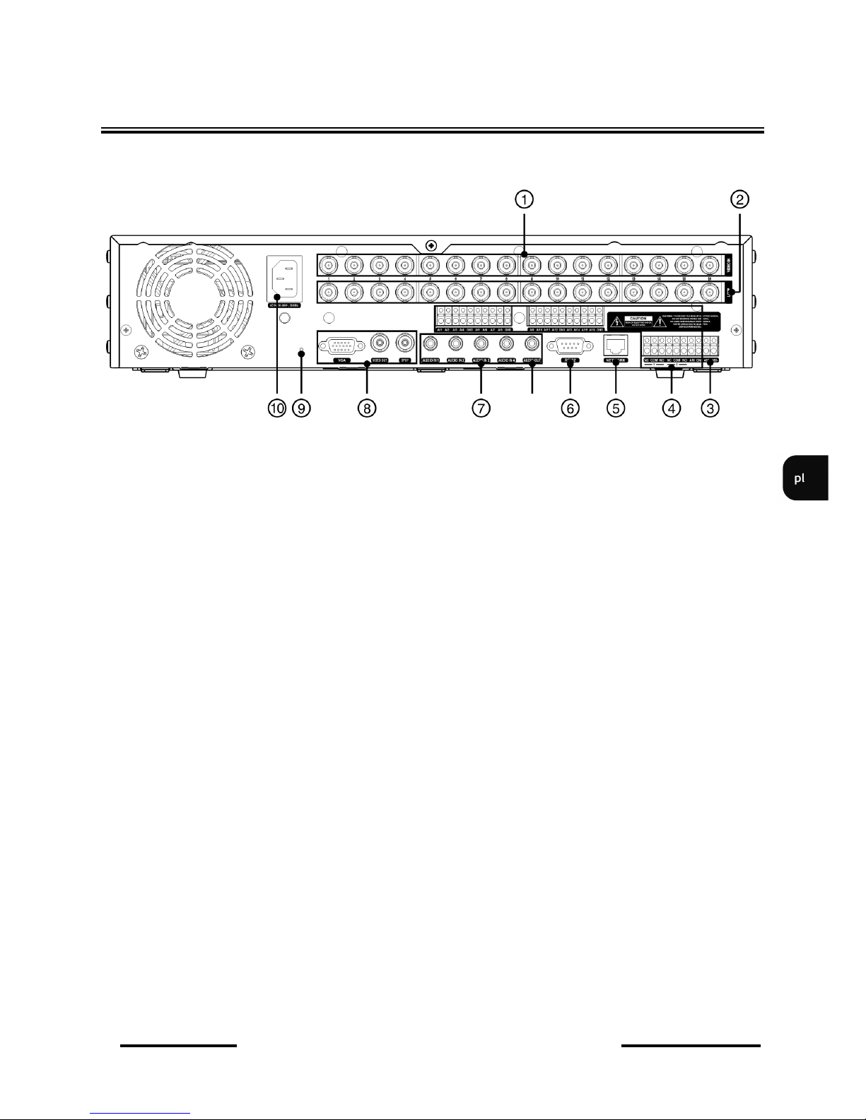
NDR-HA4208, NDR-HA4416 - Instrukcja obsługi wer. 1.2
Wszelkie prawa zastrzeżone © NOVUS Security Sp. z o.o.
9
2.2. Zł
ącza elektryczne i inne elementy panelu tylnego
Widok NDR-HA4416
URUCHAMIANIE URZĄDZENIA
1. VIDEO IN : wejścia wideo do podłączenia sygnału wizyjnego z kamer
2. VIDEO LOOP: wyjścia przelotowe sygnału wizyjnego, 16 lub 8 w zależności od modelu.
3. RS-485: złącze magistrali RS-485 do podłączenia kamer, klawiatur systemowych lub
urządzeń generujących dane tekstowe. Jednocześnie możliwe jest
podłączenie tylko jednego z wymienionych urządzeń.
4. ALARM INPUTS wejścia alarmowe, które z poziomu menu mogą być ustawiane jako
normalnie otwarte (N.O.) lub normalnie zamknięte (N.C.), 16 lub 8
w zależności od modelu. Aby sygnał został zdetektowany musi trwać
co najmniej 0.5s. Wszystkie złącza oznaczone GND znajdują się na
wspólnym potencjale masy. Przewód masy urządzenia alarmowego należy
połączyć z jednym za złącz GND.
ALARM OUTPUTS rejestrator może uaktywniać zewnętrze urządzenia typu brzęczyki, lampy
halogenowe, syreny itp. Za pomocą 2 wyjść przekaźnikowych.
Obciążalność wyjścia wynosi 0,5A@125VAC i 1 A@ 30 VDC.
ARI (Alarm Reset Input):
zewnętrzny sygnał podany na złącza ARI i GND może kasować aktywne
wyjścia przekaźnikowe oraz wewnętrzny brzęczyk urządzenia.
Minimalne napięcie podanego sygnału powinno mieć wartość 0,3V
i trwać około 0,5s, aby został wykryty.
Page 90
NDR-HA4208, NDR-HA4416 - Instrukcja obsługi wer. 1.2
Wszelkie prawa zastrzeżone © NOVUS Security Sp. z o.o.
10
5. NETWORK złącze RJ-45 do podłączenia urządzenia do sieci lokalnej w standardzie
10/100Mb/s.
6. PORT RS-232: port do podłączenia zewnętrznego modemu do zdalnego podglądu, do
podłączenia zewnętrznej klawiatury sterującej (opcjonalnie) lub
urządzeń generujących informacje w postaci kodów ASCII (kasy
fiskalne, bankomaty itp.). Jednocześnie możliwe jest podłączenie
tylko jednego z wymienionych urządzeń. W przypadku podłączenia
urządzenia posiadającego inny interfejs niż RS-232 wymagane jest
zastosowanie odpowiedniego konwertera np. do zmiany transmisji ze
standardu RS-485 na RS-232 np. NV-001RSC
Uwaga: Kabel do połączenia z portem RS-232 nie jest dostarczany
z urządzeniem. Należy upewnić się, że posiadany kabel jest właściwy
(złącze DB9S żeńskie).
7. AUDIO IN /OUT: 4 wejścia audio mono (złącza typu RCA) do podłączenia mikrofonów.
Uwaga: rejestracja dźwięku może odbywać się jedynie w przypadku gdy
regulacje prawne danego kraju na to pozwalają.
Tory audio wejść mikrofonowych nie zostały wyposażone
w przedwzmacniacze i dlatego nie należy podłączać bezpośrednio
mikrofonów lecz należy stosować w torach przedwzmacniacze.
Jedno wyjście audio do podłączenia głośnika ze wzmacniaczem.
Wyjście głośnikowe nie posiada w torze audio wzmacniacza
i dlatego należy stosować głośniki ze wzmacniaczem.
Widok NV-DVR5116(S)DVD
URUCHAMIANIE URZĄDZENIA
Page 91
NDR-HA4208, NDR-HA4416 - Instrukcja obsługi wer. 1.2
Wszelkie prawa zastrzeżone © NOVUS Security Sp. z o.o.
11
URUCHAMIANIE URZĄDZENIA
Widok NDR-HA4416
8. VIDEO OUT/ SPOT 1/ VGA
wyjście VGA do podłączenia monitora głównego w trybie VGA
(komputerowego). Należy użyć kabla sygnałowego dostarczanego wraz
z monitorem.
złącza VIDEO OUT do podłączenia głównego monitora, możliwe jest
wybranie jednego z wielu trybów wyświetlania.
wyjście SPOT do podłączenia monitora pomocniczego (dodatkowego),
wyświetlanie w trybie pełnoekranowym dowolnej kamery lub sekwencji
kamer.
9. RESET przywraca rejestrator do ustawień fabrycznych
10. gniazdo do podłączenia przewodu sieciowego 230 V AC, należy
upewnić się, że wtyczka jest właściwie włożona i zapewnia stabilne
połączenie między stykami oraz podłączona jest do sieci z uziemieniem, nie
należy nadmiernie zginać kabla zasilającego.
Page 92
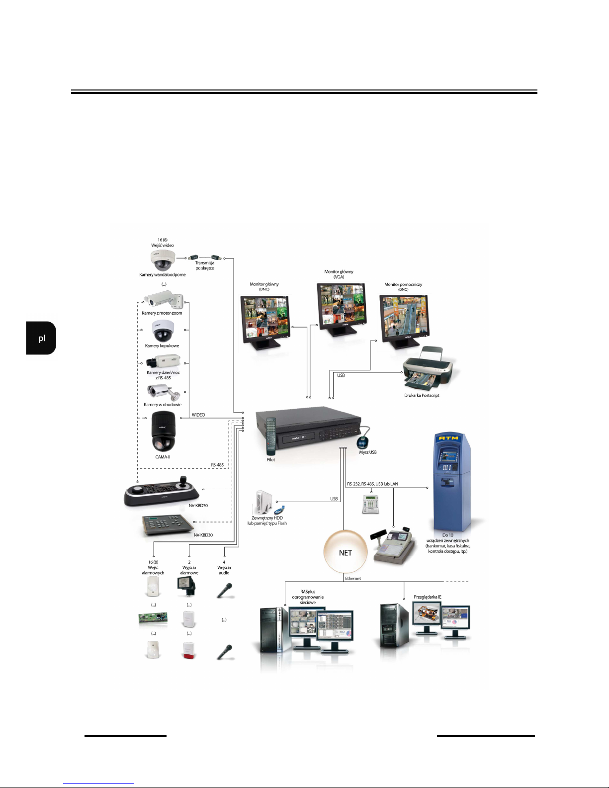
NDR-HA4208, NDR-HA4416 - Instrukcja obsługi wer. 1.2
Wszelkie prawa zastrzeżone © NOVUS Security Sp. z o.o.
12
2.3. Podłączanie urządzeń peryferyjnych
Połączenie systemu powinno być przeprowadzone przez wykwalifikowany personel.
Przed wykonaniem połączeń należy zapoznać się ze schematem przedstawionym poniżej, który jest
schematem poglądowym. W zależności od wymagań, konkretny system będzie składał się z różnej
liczby urządzeń peryferyjnych. Monitory, kamery i inne urządzenia należy zakupić oddzielnie
w zależności od potrzeb. Opis podłączania niektórych urządzeń zewnętrznych znajduje się rozdziałach
5, 6, 7 i 8 instrukcji.
URUCHAMIANIE URZĄDZENIA
Page 93
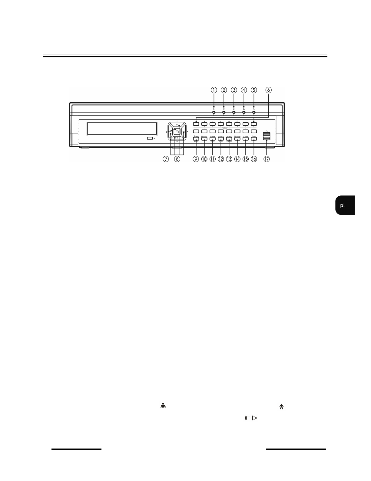
NDR-HA4208, NDR-HA4416 - Instrukcja obsługi wer. 1.2
Wszelkie prawa zastrzeżone © NOVUS Security Sp. z o.o.
13
2.4. Opis płyty czołowej
Widok NDR-HA4416
URUCHAMIANIE URZĄDZENIA
UWAGA: do sterowania rejestratorem oraz dokonywania ustawień menu można użyć myszy
z interfejsem USB oraz klawiatury systemowej. Szczegóły dotyczące sterowania za pomocą myszy z
interfejsem USB zawarte są w rozdziale 10 niniejszej instrukcji.
1. DIODA LED ZASILANIA Dioda świeci kiedy rejestrator jest włączony
2. DIODA LED DYSKU Dioda miga podczas nagrywania oraz wyszukiwania materiału na
dysku
3. DIODA LED ALARM Dioda świeci kiedy został wywołany alarm lub został aktywowany
wewnętrzny brzęczyk.
4. DIODA LED SIEĆ Dioda świeci kiedy rejestrator zostanie podłączony do sieci
Ethernet
5. DIODA LED KOPIA Dioda świeci podczas kopiowania.
6. 1~16 (1~8) Przyciski wyboru kanału; naciśnięcie jednego z przycisków wyboru
kanału powoduje wyświetlenie na ekranie obrazu z kamery
podłączonej do danego kanału. Obraz wyświetlany jest w trybie
pełnoekranowym. Przyciski wyboru kanału wykorzystywane są do
ustawienia i wpisania hasła. Przytrzymanie prze okres trzech
sekund dowolnego przycisku wyboru kanału pozwala na wejście
do menu ustawień obrazu (jasności, kontrastu, nasycenia, odcienia
barwy).
W trybie PTZ wciśnięcie przycisku 1 powoduje przybliżenie
obrazu , przycisk 2 powoduje oddalenie obrazu, , p rzyci s k
3,4 umożliwiają ustawienie ostrości ,przycisk 5 powoduje
przej
ście do PRESETU, 6 zapisuje PRESET
Page 94
NDR-HA4208, NDR-HA4416 - Instrukcja obsługi wer. 1.2
Wszelkie prawa zastrzeżone © NOVUS Security Sp. z o.o.
14
7. PLAY / PAUSE W trybie podglądu na żywo wciśnięcie przycisku p o w o d u j e
zmrożenie obrazu. Na ekranie pojawi się ikona
W trybie odtwarzania wciśnięcie przycisku PLAY/PAUSE
powoduje rozpoczęcie odtwarzania ze standardową prędkością. W
menu przycisk używany jest do zatwierdzania dokonanych zmian
podczas ustawień systemu.
8. Przyciski nawigacyjne używane są do nawigacji w menu rejestratora
oraz do zmiany wartości poszczególnych pozycji (przyciski i ). W
trybie PTZ przyciski nawigacyjne używane są do sterowania ka
merami szybkoobrotowymi. W trybie wyświetlania PIP przyciski i
używane są do przemieszczania okna wyświetlania obrazu, natomiast
przyciski i do zmiany rozmiaru okna PIP.
W trybie odtwarzania naciśnięcie przycisku szybkiego od twarzania
powoduje zwiększenie prędkości odtwarzania w przód lub w tył..
Zmiana prędkości odtwarzania realizowane jest poprzez kolejne
naciśnięcia przycisku lub .
Prędkościom odtwarzania towarzyszą wyświetlane na e k r a n i e
monitora następujące znaki graficzne:
W trybie pauzy użycie przycisku lub powoduje przejście do po
przedniego lub następnego obrazu
9. MENU/CAMEO Naciśnięcie przycisku MENU pozwala wejść do ustawień rejestratora.
Na ekranie wyświetlone zostanie menu, którego opis znajduj się w
dalszej części instrukcji.
Naciśnięcie przycisku MENU w trybie podziału i przetrzymanie
przez ok. 2s powoduje uruchomienie funkcji sekwencji w podziale.
Funkcja umożliwia edytowanie kolejności wyświetlanych kamer
w podziale na monitorze głównym oraz uruchomienie sekwencji
wyświetlania kamer na monitorze pomocniczym.
10. PLAYBACK Wciśnięcie przycisku PLAYBACK powoduje przejście do trybu
odtwarzania. Ponowne wciśnięcie PLAYBACK powoduje powrót do
trybu podglądu na żywo.
URUCHAMIANIE URZĄDZENIA
▲
▼
▼
► ◄
▲
Page 95
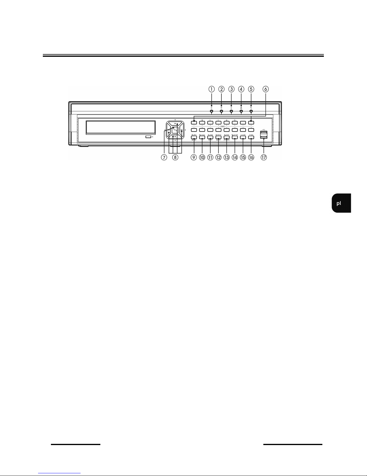
NDR-HA4208, NDR-HA4416 - Instrukcja obsługi wer. 1.2
Wszelkie prawa zastrzeżone © NOVUS Security Sp. z o.o.
15
11. ZOOM/PTZ Naciśnięcie przycisku powoduje powiększenie aktualnie
wyświetlanego obrazu. W automatycznie włączanej f u n k c j i
obrazu w obrazie uaktywnia się biały prostokąt wsk azują cy,
który obszar z pola widzenia kamery został powiększony.
Za pomocą przycisków nawigacyjnych prostokąt powiększenia
może być przesuwany.
Wciśnięcie i przetrzymanie przycisku ZOOM/PTZ powoduje
przejście do trybu PTZ wybranej kamery. Ikona PTZ miga na
ekranie. Sterowanie poprawnie skonfigurowaną kamerą odbywa
się za pomocą przycisków nawigacyjnych oraz MENU.
12. DISPLAY Przycisk posiada dwie funkcje. Kolejne naciśnięcia
przycisku powodują zmianę formatu wyświetlania. Dostępne
formaty wyświetlania: pełny ekran, 2x2, 3x3, 4x4 i funkcja PIP
(obraz w obrazie). Wciśnięcie i przetrzymanie przycisku przez 2 s
umożliwia wybór wyświetlanej kamery na monitorze
pomocniczym.
13. SEQUENCE W trybie „na żywo” naciśnięcie przycisku powoduje
wyświetlanie kolejnych kamer w trybie pełnoekranowym.
Wciśnięcie i przetrzymanie przycisku przez 2 s umożliwia
uruchomienie sekwencyjnego wyświetlania obrazów z kamer.
14. CLIP COPY Przycisk umożliwia kopiowanie wybranego materiału na CD/
DVD lub Flash USB.
URUCHAMIANIE URZĄDZENIA
ZOOM
DISPLAY
Widok NDR-HA4416
Page 96

NDR-HA4208, NDR-HA4416 - Instrukcja obsługi wer. 1.2
Wszelkie prawa zastrzeżone © NOVUS Security Sp. z o.o.
16
15. ALARM Naciśnięcie przycisku powodu je skasowa nie
wewnętrznego brzęczyka urządzenia i aktywnych wyjśc
przekaźnikowych. Naciśnięcie przycisku w trybie “live”
powoduje wejście do rejestru zdarzeń. Powyższa funkcja może
być chroniona hasłem.
16.PANIC Naciśnięcie przycisku napadowego powoduje
rozpoczęcie nagrywania sygnałów wizji z wszystkich kamer
i wyświetlenie ikony na monitorze głównym.
17. USB Port USB do podłączenia myszy USB i pamięci Flash
2.5. Instalacja dysków twardych
Rejestratory NDR-HA4208 i NDR-HA4416 pozwalają na zainstalowanie 3 dysków twardych SATA
oraz nagrywarki DVD.. Możliwość zamontowania 4 HDD dostępna jest po dokupieniu
odpowiedniego zestawu montażowego.
UWAGA: W celu uzyskania informacji o kompatybilnych modelach twardych dysków oraz
maksymalnych ich pojemnościach należy skontaktować się z dystrybutorem lub
sprawdzić na stronie www.novuscctv.com. Firma Novus nie ponosi
odpowiedzialności za problemy wynikłe ze stosowania nie zalecanych dysków
twardych.
UWAGA: Lista kompatybilnych dysków zawiera wszystkie dyski poprawnie współpracujące z
danym rejestratorem, w tym także przeznaczone do pracy biurowej tzw. desktopowe.
Jednak ze względu na to, że w systemach CCTV priorytetem jest niezawodność
procesu rejestracji i zarządzania danymi zaleca się stosowanie dysków
przeznaczonych do pracy ciągłej tzw. 24x7.
UWAGA: Jeżeli użyty dysk był stosowany w innym urządzeniu konieczne jest jego
formatowanie. Należy mieć to na uwadze ze względu na utratę danych.
WŁĄCZENIE ZASILANIA
Podłączenie kabla zasilającego do urządzenia rozpoczyna pracę rejestratora. Inicjalizacja
systemu trwa około 60 sekund. W tym czasie nie należy uruchamiać żadnych funkcji urządzenia
i naciskać żadnych przycisków. Wyłączenie urządzenia odbywa się za pomocą menu (rozdział
3.1.5).
URUCHAMIANIE URZĄDZENIA
ALARM
ALARM
PANIC
Page 97
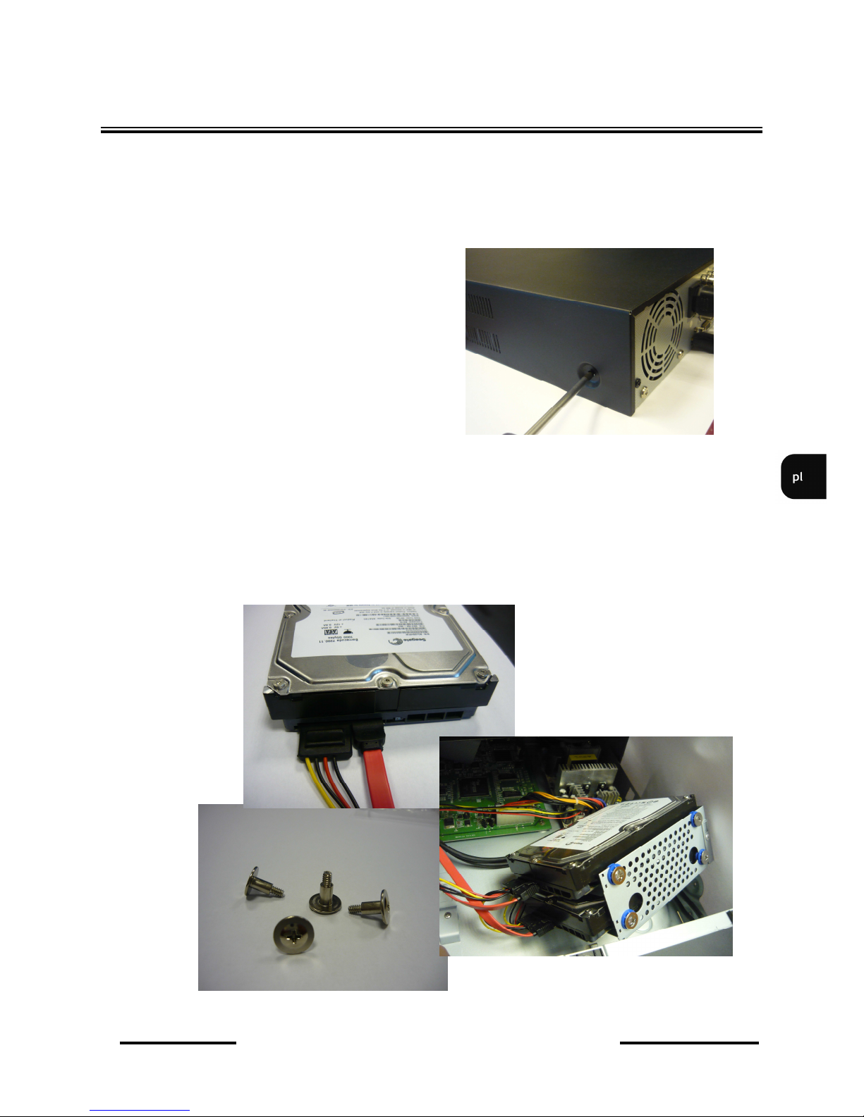
NDR-HA4208, NDR-HA4416 - Instrukcja obsługi wer. 1.2
Wszelkie prawa zastrzeżone © NOVUS Security Sp. z o.o.
17
NOTATKI
Przed zdjęciem obudowy należy się upewnić czy kabel zasilający został odłączony od rejestratora.
W celu zamontowania nagrywarki DVD i/lub dysków HDD
Należy:
1. Zdjąć górną cześć obudowy rejestratora.
2. Zainstalować dyski w specjalnym koszyku śrubami dołączonymi w zestawie. Podłączyć kable
zasilające oraz kable SATA.
URUCHAMIANIE URZĄDZENIA
Page 98
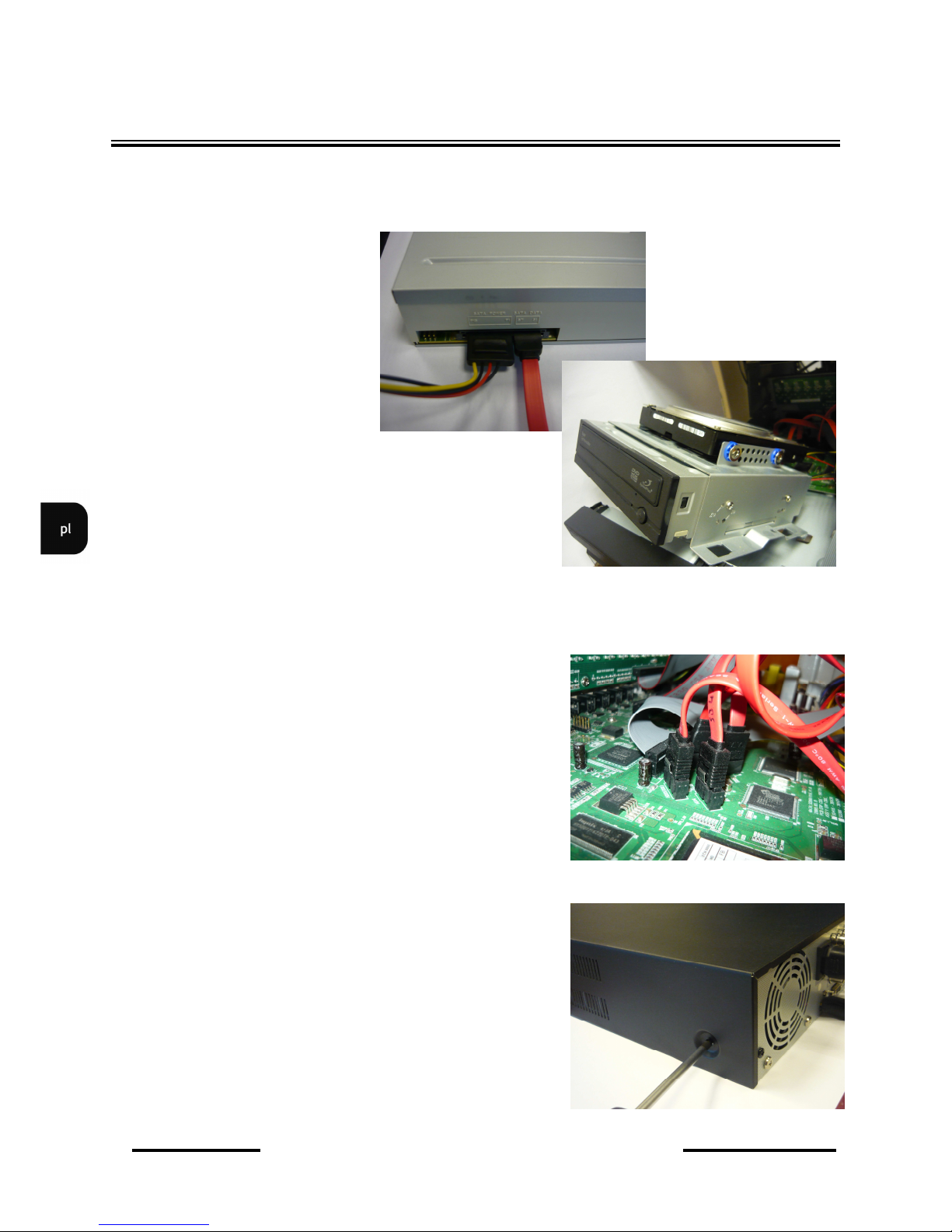
NDR-HA4208, NDR-HA4416 - Instrukcja obsługi wer. 1.2
Wszelkie prawa zastrzeżone © NOVUS Security Sp. z o.o.
18
NOTATKI URUCHAMIANIE URZĄDZENIA
3. Zainstalować dysk HDD i/lub nagrywarkę DVD w specjalnym koszyku. Podłączyć kable
zasilające oraz kable SATA. Śruby do zamontowania DVD-RW dostarczane są przez producenta
nagrywarki.
4. Podłączyć dyski i nagrywarkę DVD-RW do płyty głównej rejestratora kablami SATA.
5. Założyć górną cześć obudowy i skręcić obudowę
rejestratora.
Page 99
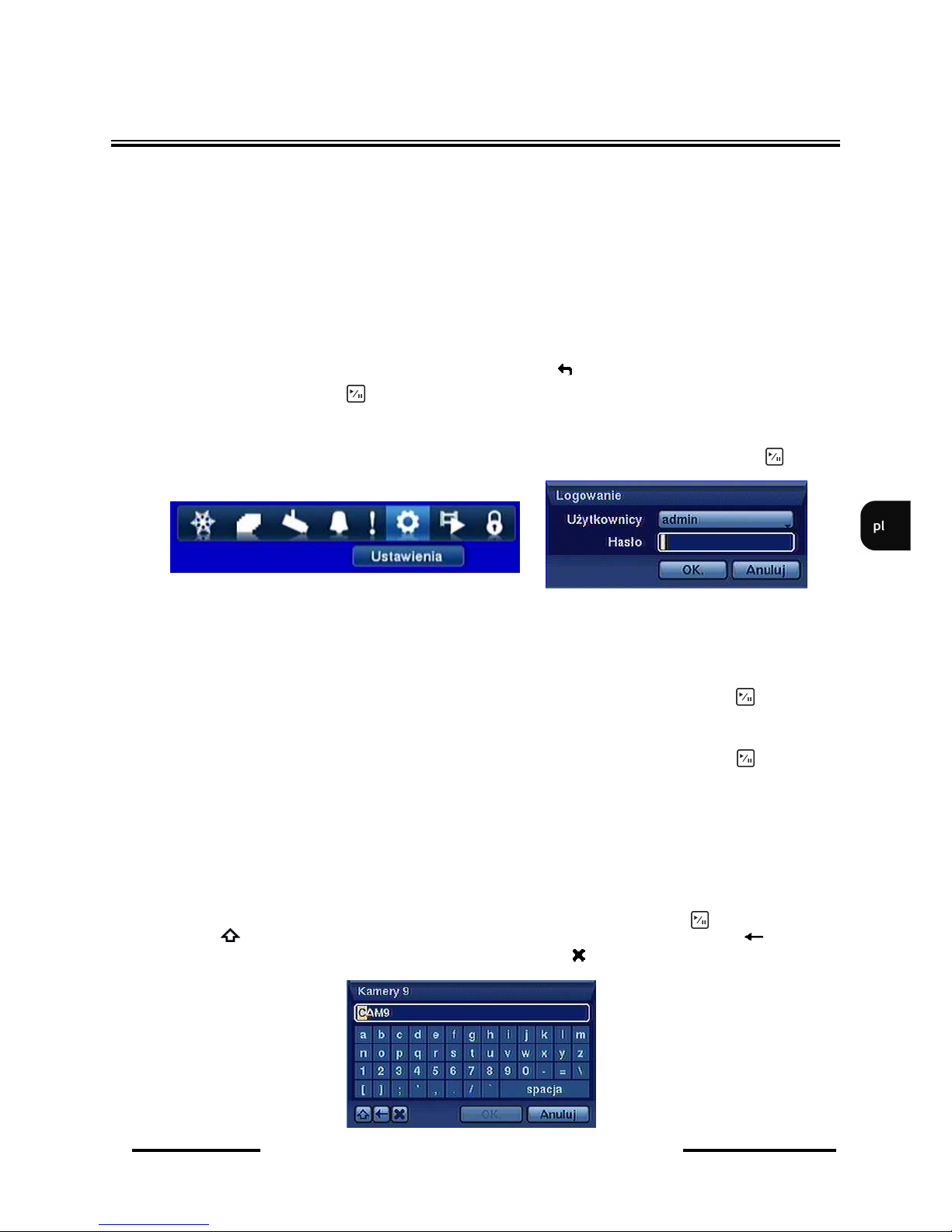
NDR-HA4208, NDR-HA4416 - Instrukcja obsługi wer. 1.2
Wszelkie prawa zastrzeżone © NOVUS Security Sp. z o.o.
19
MENU REJESTRATORA
3. MENU REJESTRATORA
Rejestratory NDR-HA4208 i NDR-HA4416 posiadają wielopoziomowe menu wyświetlane na ekranie
monitora służące do programowania ustawień.
Menu urządzenia jest wielojęzyczne i wyświetlane w jednym z poniższych języków: angielski,
niemiecki, hiszpański, francuski, włoski, polski, rosyjski, węgierski i czeski.
Menu dla urządzeń w wersji 8 i 16 kanałowej różnią się jedynie ilością poszczególnych kanałów
wizji, wejść alarmowych itd.
Przed rozpoczęciem użytkowania rejestratora należy dokonać wstępnych ustawień menu w zakresie
daty i czasu, języka menu, haseł, zdalnej kontroli, dostępu sieciowego itp.
W poszczególnych zakładkach menu znajduje się ikona . Najechanie kursorem na tę ikonę
i naciś nię cie przycisku powoduje powrót do ustawień fabrycznych danej zakładki menu.
Aby wejść do menu ustawień rejestratora należy nacisnąć przycisk MENU. Pojawi się ekran
logowania jak poniżej. Należy wybrać ikonę USTAWIENIA, a następnie wcisnąć klawisz
Aby zalogować się do urządzenia należy w pozycji UŻYTKOWNICY wybrać użytkownika oraz
w pozycji hasło za pomocą przycisków kamerowych 1~9 wpisać hasło użytkownika.
W przypadku pierwszego logowania dla użytkownika ADMIN domyślnie nie jest ustawione
hasło! Oznacza to, że pole HASŁO należy zostawić puste i nacisnąć przycisk na panelu
czołowym.
Do poruszania się po menu służą przyciski nawigacyjne oznaczone strzałkami.
Do zatwierdzania wyboru, wchodzenia w pod-menu i w pola edytowalne służy przycisk .
Zmiany wartości dokonuje się za pomocą przycisków strzałek.
Do wyjścia z trybu programowania lub do wyjścia poziom wyżej z poszczególnych pod-menu i pól
edycji służy przycisk MENU. W celu ustawienia tej samej wartości dla wszystkich pozycji
w kolumnie należy najechać kursorem na pozycję nazwa kolumny z trzema kropeczkami
oznaczającymi możliwość globalnych ustawień i dokonać ustawień.
Dla wielu pozycji menu rejestratora wymagane jest wpisanie nazwy lub tytułu. Po wybraniu
edytowalnej pozycji na ekranie monitora pojawia się wirtualna klawiatura. Wybór znaków
dokonywany jest za pomocą klawiszy nawigacyjnych i zatwierdzony przyciskiem .
Wybór znaku przełącza klawiaturę na system liter dużych lub małych, znak oznacza
klawisz BACKSPACE tradycyjnej klawiatury, natomiast znak kasuje wprowadzone znaki.
Page 100
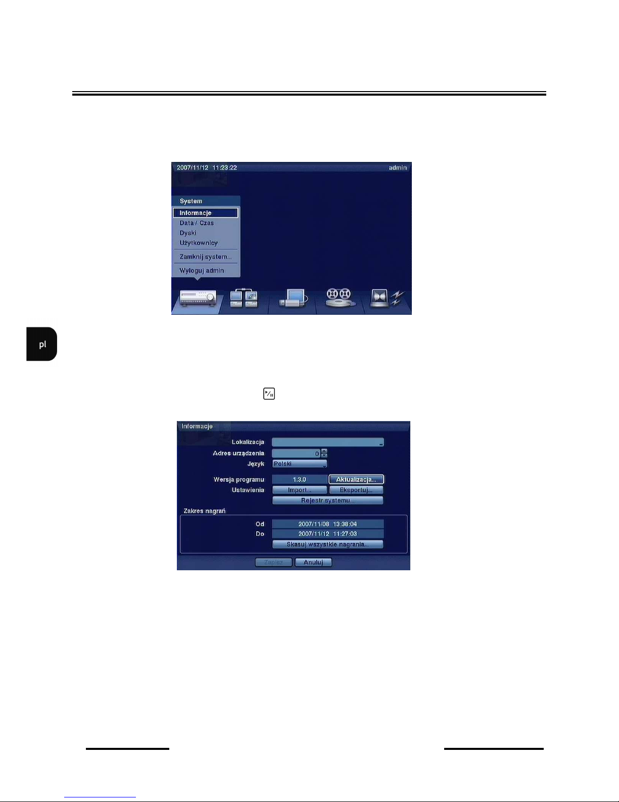
NDR-HA4208, NDR-HA4416 - Instrukcja obsługi wer. 1.2
Wszelkie prawa zastrzeżone © NOVUS Security Sp. z o.o.
20
3.1. System
Po naciśnięciu przycisku MENU i wpisaniu hasła użytkownika pojawi się poniższy ekran:
W menu SYSTEM znajduje się pięć pod-menu dotyczących ustawień systemowych rejestratora.
3.1.1. Informacje
Po wybraniu tego pod-menu i naciśnięciu pojawi się poniższy ekran:
W pozycji LOKALIZACJA za pomocą wirtualnej klawiatury należy wpisać nazwę lokalizacji
rejestratora.
W pozycji ADRES URZĄDZENIA za pomocą klawiszy nawigacyjnych góra - dół należy ustawić
numer identyfikacyjny (ID) urządzenia.
Uwaga: Numer identyfikacyjny (ID) urządzenia jest wykorzystywany do identyfikacji urządzenia
w sieci RS-485 oraz przy sterowaniu zdalnym pilotem. W przypadku, gdy w sieci znajduje się więcej
niż jeden rejestrator każdy z nich musi posiadać unikalny adres ID. Jeżeli więcej niż jeden rejestrator
posiada adres ID równy 0 to mogą być sterowane równocześnie z poziomu pilota zdalnego sterowania.
MENU REJESTRATORA
 Loading...