

Page 1
A-STATION
A-station
in music, anything is possible.
polyphonic synthesizer
▲
User Manual
Page 2

Copyright: Novation E.M.S Limited 2001 A-Station User Guide
Version 1.1
Features and specifications subject to change without notice due
to improvements
www.novationmusic.com
Page 3

Table of Contents
Introduction....................................................................
Using this manual...................................................................
Main Features.........................................................................
Conventions used in this manual............................................
Quick Start Guide..........................................................
Connecting to audio equipment.............................................
Listening to the factory preset sounds...................................
Selecting sounds....................................................................
Auditioning a sound.................................................................
Editing a sound......................................................................
Saving a sound......................................................................
Listening to the factory demonstration...................................
Synthesis Tutorial.........................................................
Elements of a sound..............................................................
Oscillators and Waveforms......................................................
Mixer and Filter........................................................................
Envelopes and Amplifier..........................................................
LFOs and Memories...............................................................
Summary..................................................................................
Main features and operation.........................................
Volume, Portamento controls ,Function Switch and LED........
Mode select button..................................................................
Oscillators................................................................................
Mixer........................................................................................
Filter.........................................................................................
Amp and Mod Envelopes........................................................
LFO’s.......................................................................................
Advanced features........................................................
Effects......................................................................................
Delay........................................................................................
Reverb.....................................................................................
Chorus, Phaser........................................................................
Distortion..................................................................................
Panning....................................................................................
EQ Filter...................................................................................
Vocoder....................................................................................
Other Menus............................................................................
Arpeggiator..............................................................................
Oscillators................................................................................
Oscillators - FM synthesis.......................................................
Pitch and Modulation wheels...................................................
Aftertouch and Breath Control.................................................
Velocity, Triggering and Synchronisation................................
Utility Mode.............................................................................
Global Master tuning - Local On / Off.....................................
Global Midi clock - Midi sync...................................................
Global Velocity Curve, Display operation, Ext Audio Input.....
Saving (backing up) sounds to an external device.................
Loading (restoring) factory preset sounds...............................
Receiving sounds from an external device.............................
Connection diagram................................................................
Notes.....MIDI Volume... Sustain Pedal...................................
Appendix........................................................................
Factory Preset Sounds Listings and Examples.......................
Operating System Upgrade Process.......................................
Technical Specification............................................................
MIDI Controller List..................................................................
MIDI NRPN List.......................................................................
Packed Controller / NRPN Details...........................................
MIDI System Exclusive ...........................................................
MIDI Implementation Chart.....................................................
Menu Lists...............................................................................
FCC Information......................................................................
1
2
2
3
4
4
4
4
5
5
6
7
8
8
9
10
11
12
13
14
14
15
16
19
20
22
23
24
24
24
28
29
30
31
32
34
36
36
40
41
44
46
47
52
52
53
54
56
56
57
58
59
A1
A1
A3
A4
A5
A8
A9
A10
A16
A17
A20
1
Page 4

Thank you for purchasing the Novation A-Station Synthesizer.
This polyphonic sound module has evolved from the classic
Novation Bass Station, using the very latest Novation technology from award winning products such as the Nova and
SuperNovaII. It is capable of producing an enormous range of
high quality synthesized sounds and is an ideal machine for a
home studio set-up or for an experienced producer looking to
add an extra dimension of controllable sound power.
Using this Manual
This manual consists of four chapters, Introduction, Quick
Start Guide, Main Features and Operation, and Advanced
Features. For easy reference, the chapter name is printed in
the footer margin of each page. An Appendix on the final
pages lists all menu options and factory preset sounds list.
In order to become an expert user as quickly as possible, it is
recommended that this manual is read in sequence chapter by
chapter. If sound synthesis is an unfamiliar subject, then the
chapter ‘About Analogue synthesis’ will provide a useful introduction to the techniques used to electronically simulate the
sound of a musical instrument using an analogue music synthesizer.
If the general principles of Sound Synthesis are already familiar,
then the Quick Start Guide is the place to begin. Once familiar
with the main features of the machine, the Advanced Features
section which covers the Effects, Arpeggiator, Synchronisation,
Triggering and the Utilities, will provide all the information to
operate the A-Station in the most creative, productive way.
Main Features
* Four hundred Program sound locations
Two hundred factory programmed sounds are included and a
further two hundred user sound memory locations are provided
(the two hundred factory sounds may be overwritten).
* Powerful Oscillators
Three Oscillators provide Sawtooth, Square, Variable Pulse,
Triangle and Sine waves. The Sawtooth, Triangle and Sine
waveforms may be duplicated within an Oscillator to provide
thicker sounding waveforms. Synchronization and FM between
two Oscillators allow the generation of metallic or percussive
timbres. A white noise source completes the waveform engine.
* External Audio Input
The Mixer allows an external audio signal to be combined with
the Oscillators and processed through the Filter and Envelopes.
Envelopes may then be auto-triggered by the external signal.
* Filter
The filter in the A-Station Synthesizer delivers the liquid sound
of an analogue filter. Selectable Low-pass, 12dB or 24dB cut-off
curves with Resonance, Overdrive and Resonance normalize
make it easy to faithfully recreate anything from distorted rave
screams to tightly rounded bass patches.
* Vocoder
The 12 band Vocoder makes it easy to create Robot and Talky
sound effects.
2Introduction
Using this Manual - Main Features
Page 5

Introduction
* Arpeggiator
The arpeggiator features six different pattern types with
adjustable gate time for staccato effects.
* Comprehensive MIDI control spec
Adjustments of any controls transmit MIDI Controller numbers
for real time recording by a sequencer or computer.
* Powerful Effects
The effects processor includes Distortion, Stereo Chorus,
Phaser, Reverb, Synchronized Delay and Synchronized Stereo
Panning. Complex, dynamic timbres may be created using
tempo synchronized effects settings. A final output EQ and
Filter section complete with a tempo synchronized LFO allow
for a performance to be automatically filtered and time locked
from 32nd triplets through to several bars.
Conventions used in this Manual.
The word ‘Program’ refers to a collection of knob and switch
settings that define an individual ‘Sound’. These settings are
then saved as a ‘Program’ that has a corresponding number in
the machines non volatile memory.
Throughout this manual the two words, ‘Sound’ and ‘Program’
are frequently referred to and essentially have the same meaning.
Text in CAPITALS refer to a front panel control or legend (even
though the name of the control may be in lower case on the
actual front panel). It could be a knob or button. For example
FREQUENCY refers to the Filter frequency control knob.
MODE select refers to the mode select button.
Warning Mode
If for any reason the front panel switches are set to an undetermined position (mid way between one setting and another) the
display will alert the condtion by flashing the following sequence
Should this occur, simply locate the switch that is mid position
and move it left or right.
3
Main Features
Page 6
4Quick Start Guide
Connecting to audio equipment - Listening to factory preset sounds - Selecting sounds
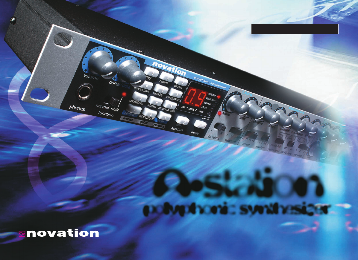
Left / Right Master Outputs
Midi Sockets Power In
Rear Panel
Selecting Sounds
There are three ways to step through the factory preset sounds.
PROGRAM mode must be selected (the Program LED is lit or
flashing). If necessary press the MODE button until it is.
There are 4 banks of 100 sounds in the A-Station named Bank
1, 2, 3 and 4
Bank 1 100 - 199 - First bank of factory preset sounds
Bank 2 200 - 299 - Second bank of factory preset sounds
Bank 3 300 - 399 - First bank of user sounds
Bank 4 400 - 499 - Second bank of user sounds
1 - Using the 0 - 9 Keypad
Ensure the FUNCTION button is set to NORMAL. There must
always be a three digit entry on the numeric keypad, for example : To select Bank 1 sound 8, press the 1, 0 and 8 buttons.
The display reads 08 and the PROGRAM LED will blink continuously indicating that the selected program is from Bank 1;
The fastest way to become familiar with the A-Station is to follow this quick start guide. It covers connecting up the AStation, listening to the factory preset sounds, selecting
sounds, editing a sound and saving a sound.
Connecting to audio equipment
Before connecting the A-Station to other units in the system,
ensure the power to all units is off. Connect an audio cable
from the Left and Right master output sockets to a suitable
amplifier or mixing desk stereo inputs. If the A-Station is to be
operated in MONO, either output may be used.
Connect the MIDI Out from a master keyboard or sequencer to
the MIDI In on the A-Station. Connect the power supply
(Novation PSU-6) to the socket ‘Power In 9VDC’ and connect
the adapter to the AC mains. Switch on the power. The AStation front panel LED display will now display the last selected program number. Switch on other units in the Audio system.
Listening to the factory preset sounds
Ensure the FUNCTION switch is set to NORMAL. Set the
VOLUME control to a reasonably high output level. This will
maintain a good signal to noise ratio. Make sure that the input
volume setting on the system amplifier or mixer is initially set to
zero.
The A-Station is set at the factory to receive on MIDI channel
1, so ensure the keyboard or sequencer is set to transmit on
this channel. Play the master keyboard or sequencer and the
currently selected factory preset sound will be heard.
Page 7
Quick Start Guide5
Auditioning a sound - Editing a sound
To select a program in Bank 2, sound 17, press the 2, 1 and 7
buttons, the display reads 17 and the program LED will blink
twice continuously indicating that the selected program is from
Bank 2; Selecting Bank 3 or 4 with a three digit entry will cause
the PROGRAM LED to blink three and four times respectively.
2 - Using the + / - Keypad buttons
Use the + and - buttons to move up or down to the next program. Pressing and holding either button for a short period will
cause the program number to advance by a further 9. This is
useful for auditioning factory preset sounds that are set ten
locations apart. For example Bass type sounds are at 100, 110,
120 etc.
3 - Using MIDI Program Change Commands
A MIDI Program change or Bank Change command sent from
an external sequencer or controller keyboard will select the
appropriate Program or Bank Number.
Auditioning a sound
As well as responding to MIDI commands from a keyboard or
sequencer, the sounds in the A-Station may be triggered or
Auditioned by pressing the AUDITION button. Each press of the
button will sequence through a selection of notes to give a clear
indication of the sound at different pitches.
Editing a Sound
Once familiar with the sounds that are available, select program
number 499. This is a very basic synthesizer sound. It can be
used as a starting point to create a new, more interesting
sound. When this sound is played from the keyboard, it will be
noticed that there is no change to the volume of the sound
other than it being on when the key is pressed, and off when
the key is released. The most useful editing controls on the AStation are on the front panel and some of these will be now be
used to modify (edit) this basic program.
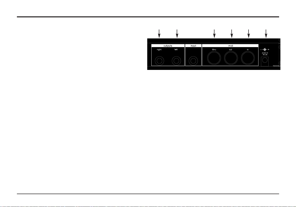
While playing the keyboard, adjust the Amplifier Envelope
SUSTAIN control. Notice that the sound level when holding a
key down changes. Set this control to just over half. Now adjust
the RELEASE control. Notice how, when a key on the keyboard
is released the sound will continue after the key is released.
How quickly the sound dies away depends on the setting of this
control.The sound is still a little too bright. Adjust the FREQUENCY control in the filter area. Notice how the sound
becomes softer as the control is rotated anticlockwise. Continue
to make adjustments until a desired sound is heard. The first
small edit is complete on the A-Station!
The sound must now be saved if it is needed for the future.
Sustain control Release control
Page 8

6Quick Start Guide
Sounds may be saved in any location. It is recommend that the
user locations (Banks 3 and 4, 300 - 499 ) be used early on for
saving new sound creations. The factory preset sounds in
Banks 1 and 2 may also be overwritten if desired. Once these
factory presents are overwritten, they may only be retrieved by
performing a factory restore - See page 54 (A backup of the
factory preset or user programs, either one by one or by bank
may be made to an external MIDI storage device - See page
54)
NOTE: When the A-Station is shipped from the factory, the
global memory protect switch is set to on. In order to save a
sound, the global memory protect must be switched off.
Switching off Global Memory Protect
Press the MODE button repeatedly until the UTILITY LED is lit.
Press the +(UNPROTECT) button once. The LED above and to
the right of the FUNCTION switch will now light indicating that
memory protect is now off (writing is enabled).
To save a program in the same location
Assuming the sound in location 499 has been edited, it may be
saved in the same location or a different one. To save it in the
same location, repeatedly press the MODE button until the
SAVE mode LED is lit.
Press the + (WRITE) button once. The write and edit dots on
the LED display will flash once to confirm that a new program
has been written. If a program is written and there has been no
edits (changes to the sound) then the write dot only on the LED
display will flash. Once a sound has been written, the operating
MODE will automatically return to PROGRAM mode.
NOTE: Any edits to any parameters will cause the edit LED to
light.
NOTE: Since there is only a two digit display available, a value
of any parameter greater than 99 (100 - 127) will be displayed
as (00. - 27.) Negative values greater than -9 will also be displayed as 10. - 63."
To save a program in a different location
Press the MODE select button until the SAVE LED is lit. Using
the keypad buttons 0 - 9 only, select the program number
where the new program is to be stored. Remember this is a
three digit entry, (100 - 499)
Press the + (WRITE) once. The write dot (and the edit dot if
there has been an edit) on the LED display will flash once to
confirm that a new program has been written. Once a sound
has been written, the MODE will automatically return to PROGRAM mode.
Using the Compare Function
After editing a sound it may be useful to compare it to the originally stored program.
Press the MODE button until the SAVE mode LED is lit.
Hold down the - (COMPARE) button. The sound being listened
to will be the originally stored program. Releasing the - (COMPARE) button will switch to listening to the edited sound again.
To save the edited sound, press the + (WRITE) button.
Saving a sound
Saving a sound
Page 9

Quick Start Guide7
Listening to the factory demonstration
Listening to the factory demonstration
To complete this Quick Start Guide section, some time spent
listening to the sounds that the A-Station is capable of producing will be of benefit when it comes to creating new sounds.
Press the MODE select button repeatedly until the UTILITY
LED is lit. Press the AUDITION (demo) button. The Factory
demonstration will begin to play. To stop the demonstration,
either press the AUDITION (demo) button again or press the
MODE button to return to program mode.
Page 10
It is recommended that this chapter is read carefully if Analogue
sound synthesis is an unfamiliar subject. Experienced users
can skip this chapter and move to the chapter - Main features
and Operation on Page 14.
Elements of a Sound
To gain an understanding of how a Synthesizer generates
sound it is helpful to have an understanding of the components
that make up a sound, be it musical or non musical.
The only way that a sound may be detected is by air vibrating
the eardrum in a regular, periodic manner. The brain interprets
these vibrations (very accurately) into one of an infinite number
of different types of sound.
Remarkably, any sound may be described by just three terms,
and all sounds always have them. They are :
* Volume
* Pitch
* Tone
What makes one sound different to another is how these three
terms change during the duration of the sound.
In a musical synthesizer we deliberately set out to have precise
control over these three terms and, in particular, how they can
be changed throughout the duration of the sound. These terms
are often given different names, Volume is referred to as
Amplitude, Pitch as Frequency and Tone as Timbre.
Pitch
Taking the example of air vibrating the ear drum, the pitch is
determined by how fast the vibrations are. For an adult human
the lowest vibration perceived as sound is about twenty times a
second, which the brain interprets as a bass type sound, and
the highest is many thousands of times a second, which the
brain interprets as a treble type sound.
Tone
Musical sounds consist of several different related pitches
occurring simultaneously. The loudest is referred to as the
‘Fundamental’ pitch Pitches related to the fundamental are
called harmonics. The relative loudness of these harmonics
compared to the loudness of all the other harmonics (including
the fundamental) determines the tone or ‘Timbre’ of the sound.
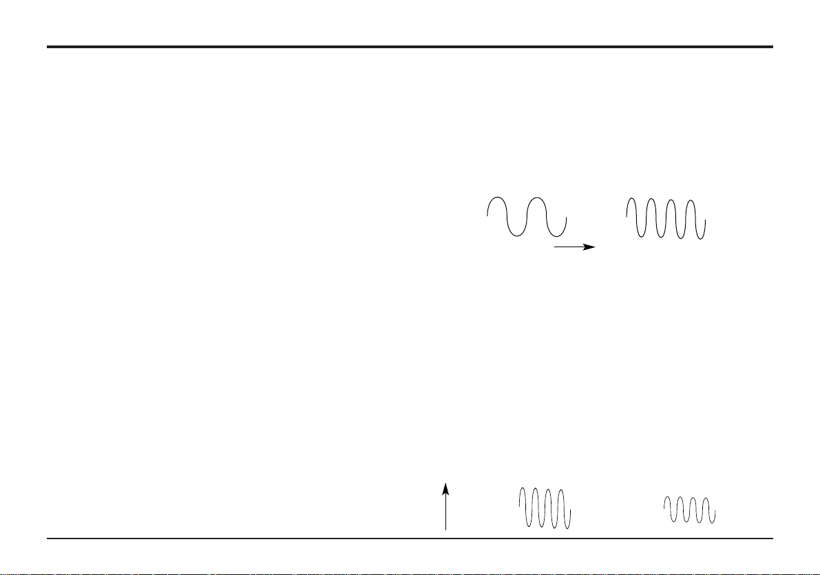
Volume
Volume, which is referred to as the amplitude or loudness of the
sound is determined by how large the vibrations are. Very simply, listening to a piano from a metre away would sound louder
than if it were fifty metres away.
8Synthesis Tutorial
Elements of a Sound
Wave A
Wave B
Time
Wave B is twice the Pitch of Wave A
Wave A
Wave B
Volume
Wave A is louder than Wave B but is the same pitch
Page 11
Having shown that just three elements make up a sound, these
elements now have to be related to a Musical synthesizer. It is
logical that a different section of the Synthesizer ‘synthesizes’
these different elements.
Oscillators and Waveforms
The Oscillator is really the heartbeat of the Synthesizer. It generates an electronic wave (which creates the vibrations) at a
controllable musical pitch that has a distinctive tone or timbre.
Many years ago pioneers of musical synthesis discovered that
just a few distinctive waves contained most of the useful harmonics for musical synthesis. They are known as, Sine waves,
Square waves, Sawtooth waves, Triangle waves and Noise
Waves.
Each one has a specific fixed amount of musically related harmonics (except noise waves) that can be manipulated by other
sections of the Synthesizer. These waves are referred to as
Waveforms.
A piece of equipment known as an Oscilloscope is able to display these waveforms on a television type screen. The name
given to the waveform is simply because, when viewed on this
piece of equipment, it looks like its named wave.
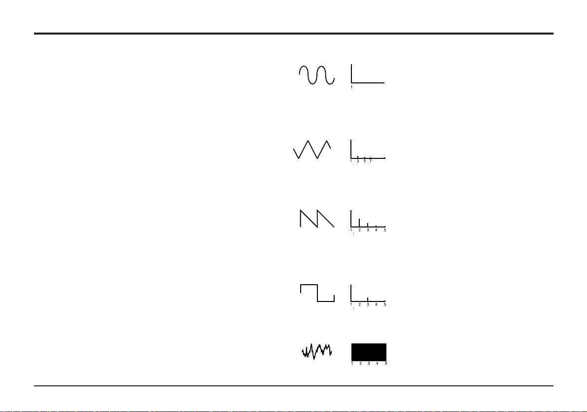
The diagrams show how these waveforms look on the
Oscilloscope and illustrate the relative volumes of their harmonics.
In summary, the Oscillators generate Waveforms at a controllable pitch. These Waveforms determine the character (Timbre)
of the sound.
9
Oscillators and Waveforms
Synthesis Tutorial
Sine waves have just a single fre-
quency. This waveform produces
the purest sound because it only
has this single pitch (frequency).
Triangle waves contain odd harmonics only. The volume of each is
the square of its position in the
harmonic series. For example, the
5th harmonic has a volume of
1/25th of the fundamental.
Sawtooth waves contain all the
harmonics of the fundamental frequency. The volume of each harmonic is proportional to its position
in the harmonic series.
Square waves have only the odd
harmonics present. These are at
the same volume as the odd harmonics in a sawtooth wave.
Noise waves have no fundamental
frequency and all frequencies are at
the same volume.
Sine Wave
Volume
Volume
Volume
Volume
Volume
Harmonic
Harmonic
Triangle Wave
Harmonic
Sawtooth Wave
Harmonic
Square Wave
Harmonic
Noise
Page 12
10Synthesis Tutorial
To extend the range of sounds that may be reproduced, a typical Analogue synthesizer has more than one Oscillator. The AStation has three independent Oscillators and a separate Noise
Oscillator.
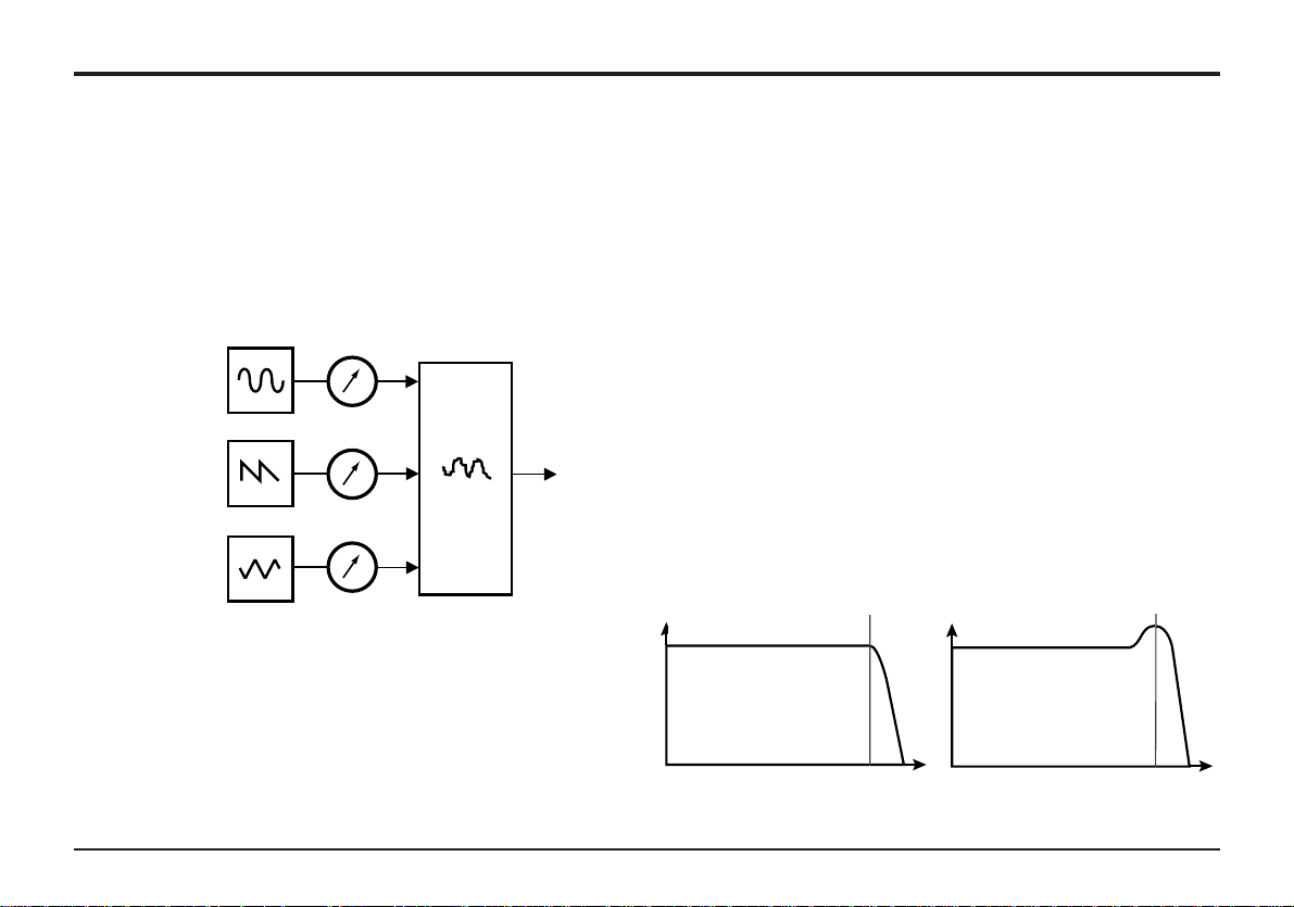
For flexibility, a mixer section is included so that the amplitude
(volume level) of each of the Oscillators may be adjusted independently and mixed together to form a harmonically complex
waveform.
Filter
The A-Station is an Analogue subtractive type of music synthesizer. Subtractive implies that part of the sound is subtracted
somewhere in the synthesis process.
The Oscillators provide the raw waveforms with plenty of harmonic content and it is the Filter that subtracts harmonics in a
controllable manner.
The Filter in the A-Station is a Low Pass type. A cut-off point is
chosen and any frequencies below the point are passed and
any above are filtered out. This process of removing harmonics
from the waveforms has the effect of changing the sounds character or timbre.
In practice there is a gradual reduction in the volume of the harmonics above the cut-off point. How quickly these harmonics
are reduced in volume above the cut-off frequency is determined by the Filter’s slope. This slope is measured in ‘volume
units per octave’ Since Volume is measured in decibels this
slope is quoted in number of decibels per octave (dB). Typical
values are 12dB or 24 dB per Octave. The higher the number,
the faster the harmonics are cut and the more pronounced the
filtering effect.
A further important feature of the Filter is the Resonance control. Frequencies at the cut-off point may be increased in volume by this control. This is useful for emphasizing certain harmonics of the sound.
Mixer and Filter
Response of a typical low
pass filter. Frequencies
above the cut off point are
reduced in volume
When resonance is added,
frequencies at the cut off
point are boosted in volume
OSC1
OSC1 VOLUME
MIXER
INPUT TO
FILTER
COMPLEX
WAVEFORM
MIX OF
OSC1,2 AND 3
OSC2 VOLUME
OSC3 VOLUME
OSC2
OSC3
Volume
Volume
Frequency
Frequency
Cut off
Frequency
Cut off
Frequency
Mixer
Page 13
11
Envelopes and Amplifier
Synthesis Tutorial
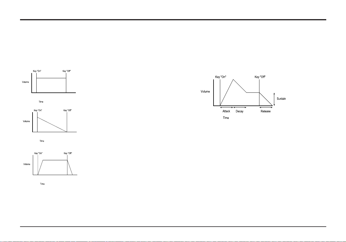
An Organ sound quickly attains
full volume when a key is
pressed. It stays at full volume
until the key is released, at which
point the volume falls to zero.
A Piano
quickly attains
full volume when a key is pressed and
gradually falls back down to
zero after several seconds, even
if a key is held.
A String Section emulation
attains
full volume graduall when
a key is pressed. It remains at
full volume until the key is
released, when gradually, the
volume falls to zero.
A = Attack time. Adjusts the time it takes when a key is
pressed for the envelope to climb from zero to full volume. It
can be used to create a sound with a slow fade in.
D = Decay time. Adjusts the time it takes for the envelope to
decay from full volume to the level set by the Sustain control.
S = Sustain level. Sets the level that the envelope remains at
while the key is held down.
R = Release time. Adjusts the time it takes when key is
released from the Sustain level to zero. It can be used to create sounds that slowly fade away in volume.
Envelopes and Amplifier
In earlier paragraphs, it was determined how the pitch and timbre of a sound is synthesized. This final part describes how the
volume is controlled. The volume throughout the duration of a
sound created by a musical instrument varies greatly according
to the type of instrument.
The diagrams show how three instruments have very different
volume characteristics. These volume intensity curves are
referred to as volume envelopes.
In an Analogue synthesizer, an Envelope Generator circuit is
connected to an Amplifier, which controls the Volume of the
sound.
The envelope generators have four controls that are used to
adjust the shape of the envelope.
When controlling Volume, these controls adjust the following
phases of the Envelope as shown in the illustration.
Page 14

12Synthesis Tutorial
LFOs and Memories
A typical synthesizer will have one or more envelopes. One is
always applied to the amplifier. Additional envlopes are typically
used to modify the filter cut off frequency or change an oscillators pitch.
LFOs
The electronic building blocks so far described allow a sound to
be synthesized. However, apart from the volume changing
throughout the duration, the sound would be fairly static and
uninteresting.
Most musical instruments produce sounds that vary not just in
volume but also in pitch and timbre. To generate this movement, additional sound modifying blocks are included in a typical Analogue Synthesizer. These generate low frequency wavforms of distinct shapes. They are given the name LFOs ( Low
Frequency Oscillators).
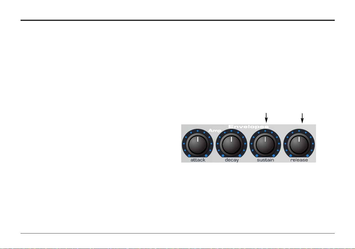
The waveforms generated by the LFO’s may be fed to other
parts of the synthesizer to create the desired movements.
A typical waveshape for an LFO would be a Triangle wave.
Imagine this slow moving wave being applied to an Oscillator’s
pitch. The result would be that the pitch slowly rises and falls
above and below its original pitch.
This would simulate, for example, a violinist moving a finger up
and down the string of the instrument whilst it is being bowed.
This subtle up and down movement of pitch is referred to as
the ‘Vibrato’ effect.
As well as LFOs being available to modify (or more commonly
known as Modulate) different sections of the synthesizer, additional Envelopes may also be used.
Clearly the more Oscillators, Filters, Envelopes and LFO’s there
are in a Synthesizer, the more powerful it becomes.
Memories
Many years ago large modular machines were produced where
each part of the synthesizer was housed in a separate unit
(block). These blocks could be connected together in any combination by patch leads. Every time a new sound was required
the leads would have to be physically disconnected and reconnected.
Modern machines such as the A-Station have all the blocks in
one compact unit and the sound generating or modifying blocks
are arranged in a sensible fashion. Front panel switches and
knobs determine how each block functions and where the
sound modifying blocks such as the LFOs and Envelopes are
routed.
Page 15

Synthesis Tutorial
The settings of these front panel controls (which of course
determine the current sound) may then be stored in memory
locations in the machine which can be recalled at any time.
Summary
An Analogue synthesizer can be broken down into five main
sound generating or sound modifying (modulating) blocks.
1 Oscillators that generate Waveforms at a certain
pitches.
2 A Mixer that mixes the outputs from the Oscillators
together.
3 A Filter that cuts out certain harmonics, which changes
the characteristic or tImbre of the sound.
4 An Amplifier that is controlled by an Envelope
generator, that alters the volume of a sound over
time.
5 LFO’s and Envelopes that can be used to modulate
any of the above.
Much of the enjoyment to be had with a Synthesiser is with
experimenting with the factory preset sounds and creating new
ones. There is no substitute for ‘hands on‘ experience.
Armed with the knowledge in this chapter, and understanding
what is actually happening in the machine when tweaks to the
knobs and switches are made will make to process of creating
new and exciting sounds easy - Have fun.
13
Summary
Page 16
14Main features and operation
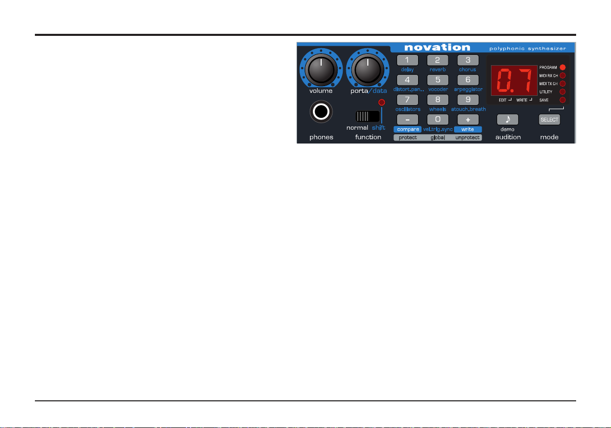
Volume and Portamento controls - Function Switch and LED
This chapter describes the main front panel controls and
how they affect a sound.
Volume knob
This knob is dual function. When the FUNCTION switch is
set to NORMAL it adjusts the overall output volume on both
the Left and Right master audio outputs on the rear panel
and the Headphone output on the front panel. Using a mixing desk as a comparison, this control can be thought of as
the channel volume fader.
When the FUNCTION switch is set to SHIFT the volume knob
adjusts the program output level. This control is used to maintain a consistent volume level without distortion throughout all
sound programs. Delicate sounds, those which use just one
Oscillator and closed filter settings, can be increased in volume
using this control. Conversely, sounds that use all Oscillators
and high polyphony (6 to 8 notes played at once), can be
reduced in volume to avoid distortion. Using a mixing desk as a
comparison, this control can be thought of as the gain or trim
control for the channel.
Portamento / Value knob
This knob is dual function. When the FUNCTION switch is set
to NORMAL (left position) it adjusts the Portamento effect.
Notes change instantly from one pitch to another when this
knob is zero. Turning the knob clockwise introduces the
Portamento effect. Notes will glide smoothly from one pitch to
the next. Increasing the amount will slow the time taken for the
pitch of the first note to reach that of the second note played.
When the FUNCTION switch is set to SHIFT (right position) this
knob adjusts the value of the data on the display. For example
if Reverb is selected, this knob will control the amount of
Reverb applied to the sound.
Function switch and LED
This switch and its associated LED behave differently depending on the MODE selected.
Function switch operation in PROGRAM MODE
Set to NORMAL, programs may be selected by using the 0-9
and + / - keys on the data entry keypad. Set to SHIFT, the 0-9
keys select the function labeled in the light blue highlighted
area below each rubber key such as Delay, Reverb. The + / keys may still be used to select the PROGRAM number. The
LED above the switch will light to indicate SHIFT selected. In
SHIFT position, certain other front panel knobs and switches
have a secondary (shifted) function. - See following pages.
LED operation SAVE and UTILITY mode
In SAVE and UTILITY mode, the LED above the FUNCTION
switch will light if writing to program memory is enabled. (Global
memory protect set to ‘off’).
Page 17

Main features and operation
15
Mode Select Button
This stereo output jack socket will drive most Stereo headphones and monitors the main Left and Right audio outputs.
Mode Select button
Selects which MODE the 0-9 keys and + / - keys are operating
in. The mode is indicated by one of five LEDs on the right hand
side of the LED display panel.
When the A-Station is switched on, PROGRAM mode is automatically selected.
Each time the button is pressed, the next operating mode will
be selected - SAVE, UTILITY, MIDI TX Channel and MIDI RX
Channel and a final loop back to PROGRAM mode. The MODE
sequence will run from the bottom to the top of the column of
LEDs.
PROGRAM MODE
Sounds (programs) may be selected using the 0-9 and + / - key
on the keypad. The PROGRAM LED indicates what program-
bank is selected.
SAVE MODE
Sounds (programs) may be compared (using - key), or written
to (using + key) a memory location in this mode. The 0 - 9
keypad buttons are used to select the destination memory location for the sound to be saved. - Also see Page 6.
UTILITY MODE
The Global Menu (which has options that affect the overall
operation of the machine and the sending of Program memories to external devices (backing up)) may be accessed in this
mode. Pressing keypad button 0 activates the Global Menu.
See Page 50 for Global settings and Page 54 for saving sounds
to external devices.
MIDI Tx CH mode allows the MIDI transmit channel to be set.
Use the PORTA/DATA knob to enter the channel number. The
recognised MIDI channel numbers are 01 to 16.
NOTE: The MIDI TX and RX channel settings are automatically
memorised when exiting from this mode.
MIDI Rx CH mode allows the MIDI receive channel. Use the
PORTA/DATA knob to enter the channel number.
The MIDI RX CH LED will flash when MIDI data is received on
the selected channel.
Mode Button Operating Mode
Power up default Program
1st Press Save
2nd Utlity
3rd MIDI Transmit Channel
4th MIDI Receive Channel
5th
Headphone Jack
Page 18
16
Oscillators
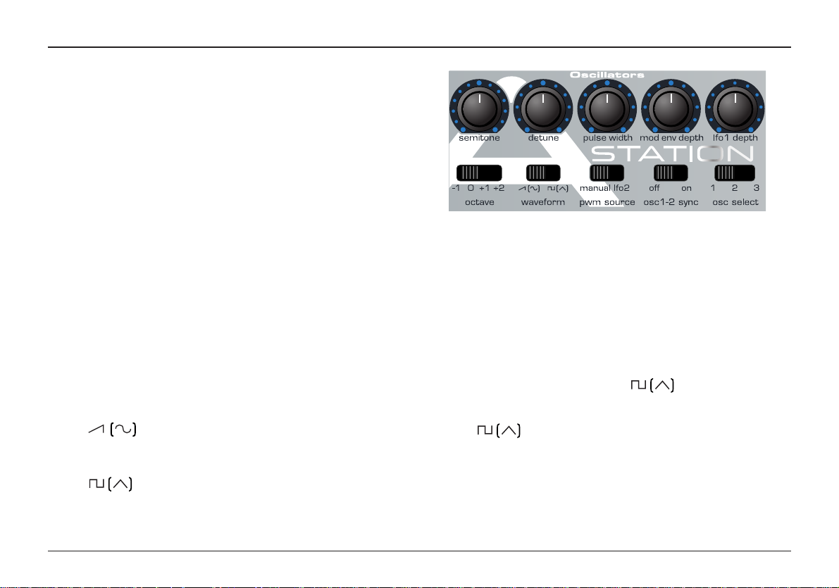
Oscillators
The Oscillators generate pitched waveforms (as described in
the Synthesis tutorial) and these are fed into the Mixer.
Most of the controls that determine the pitch and waveform of
the Oscillators, and how they react to modulation are in this
area.
Osc Select Switch
There are three independent Oscillators and each one can be
independently controlled by the switches and knobs in the
Oscillator area. To adjust the controls for Oscillator 1, select
position 1, to adjust Oscillator 2, select position 2 and to adjust
Oscillator 3, select position 3.
Octave Switch
Sets the basic pitch of Oscillator 1, 2 or 3 in Octave jumps. To
change the basic pitch of Oscillator 1, set the OSC SELECT
switch to position 1 and move the OCTAVE switch to position 1
NOTE: The 0 position corresponds to the pitch of 440Hz when
note A above middle C is played.
Waveform Switch
In the position, the selected Oscillator’s waveform will
change to Sawtooth if the FUNCTION switch is set to NORMAL or Sine if the FUNCTION switch is set to SHIFT.
In the position, the selected Oscillators waveform will
change to Square if the FUNCTION switch is set to NORMAL
or Triangle if the FUNCTION switch is set to SHIFT.
Oscillator 1 - 2 Sync Switch
Synchronizes the waveform of Oscillator 2 to Oscillator 1. Each
time Oscillator 1 completes its cycle it resets the start cycle of
Oscillator 2. When listening to Oscillator 2 only, it has a dramatic effect on the timbre of the sound. The easiest way to illustrate the effect is to create a sound using the Oscillator Sync.
Creating a sound using the Sync Effect
Select a factory preset basic sound - preset 499. Select OSC 1
and set its WAVEFORM to square - . Turn the OSC 1 &
2 knob in the MIXER section to fully clockwise to OSC 2. Select
OSC 2 in the Oscillator Section. Select OSC 2 WAVEFORM to
square - . Play a note and listen to the sound. It will be
a simple tone.
Apply a little MODE ENV depth by turning the MOD ENV
DEPTH knob slightly clockwise from centre. Adjust the MOD
ENV ATTACK and MOD ENV DECAY in the Envelopes section.
Listen to the sound, it will now rise and fall quickly at the begin
Main features and operation
Page 19

17
Oscillators
ning of the sound and rest at a final pitch. Finally turn the OSC
1-2 sync on by sliding the switch to the ON position.
Experiment with the sound by raising the semitone pitch of
OSC 2 and by adjusting the MOD ENV ATTACK and DECAY
knobs in the Envelopes section.
PWM (Pulse Width Modulation) Source switch and Pulse
Width knob
The function of the PULSE WIDTH knob is dependent on the
PWM SOURCE switch.
With the switch in the MANUAL position, the PULSE WIDTH
knob will manually control the pulse width of a square waveform (The selected waveform for the Oscillator must be Square
for this to happen). In order to understand how the Pulse Width
knob affects other waveforms see the paragraph following titled:
Width control of other Waveforms.
With the PULSE WIDTH knob in the central position, the Pulse
Width wave becomes a square wave. As the knob is adjusted
clockwise, or anticlockwise, the Pulse Width becomes narrower,
producing thinner more nasal sounds.
With the PWM SOURCE switch in the LFO 2 position, the width
of the Pulse Wave may be modulated by either LFO 2, or, when
the FUNCTION switch is set to SHIFT, the MOD ENV. The
intensity of this modulation is determined by the PULSE WIDTH
knob. With the Pulse Width knob at central position there is no
effect. Turning clockwise or anticlockwise introduces the effect.
Continuous variation in the width of a pulse waveform (which is
what is happening when LFO 2 is modulating it) changes the
harmonic content. This is pleasing to the ear, especially at
lower pitches where all the associated harmonics fall within the
audio range.
When modulated by the MODE ENV, the effect is most apparent when using fairly long Mod Env Attack and Decay times.
Width control of other waveforms
If the square wave is not selected for the Oscillator being
adjusted by the pulse width control, its waveform will gradually
change to a double waveform of the same type as the pulse
width control is moved away from its central position.
Very thick sound textures may be created by using LFO2 to
modulate this doubling effect. To hear the effect, select a sawtooth waveform for one of the Oscillators. Set the PWM
SOURCE switch to the LFO2 position. Set LFO2’s waveform to
triangle. Introduce an amount of modulation from LFO2 by
moving the PULSE WIDTH knob from its central position.
Adjust the speed of LFO2 and notice how the speed affects the
apparent detuning ‘thickening’ of the sound.
Main features and operation
Page 20

18
Oscillators
Detune Knob
Sets the detune amount in Cents for the selected Oscillator 1,2
or 3. If it is set fully clockwise, Oscillators pitch will be 50 cents
sharper than its basic pitch, fully anticlockwise and it will be 50
cents flat.
Slight detuning between each Oscillator will enrich the sound by
introducing a beating between the Oscillators (in the same way
a 12-string guitar sounds richer than a 6-string). Bass and lead
sounds can be fattened up using a small amount of detune.
Large amounts of detuning will lead to more extreme effects.
Semitone
Raises or lowers the selected Oscillators pitch in semitone
increments up to a full octave. By setting the pitch of Oscillator
1 to zero and adjusting the pitch of Oscillator 2 and 3 by differing amounts results in some musically pleasing intervals.
Settings 5 (a perfect 4th), 7 (a perfect 5th), 3 (minor 3rd), 4
(major 3rd), 8 (minor 6th) and 9 (major 6th) offer the best
results.
Mod Env Depth Knob
Controls the amount of pitch modulation to the currently selected Oscillator from the Mod Envelope. In the centre position
there is no effect on the oscillator's pitch, anticlockwise the
effect is negative (i.e. the pitch drops and then rises) and clockwise positive (the pitch rises and then falls).
See Page 22 - Amp and Mod Envelopes, for the setting of the
rise and fall times.
LFO1 Depth Knob
Controls the amount of pitch modulation to an Oscillator from
LFO 1. It controls how much above and below the basic pitch
the Oscillator regularly rises and falls. If the LFO is set to
Triangle wave and the LFO’s speed knob is above the centre of
its range, this will produce a vibrato effect. Other effects like a
siren or sea gull cry are possible with more extreme settings.
Main features and operation
Page 21
Main features and operation19
Mixer
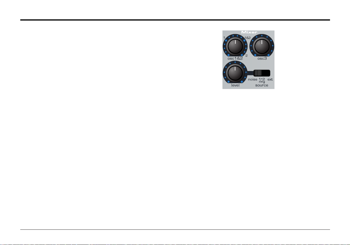
Mixer
The Mixer makes it it possible to combine the outputs of
Oscillators 1,2 and 3, the Noise source, the Ring modulator and
the external Audio Input. The ability to mix together any or all of
these sound sources makes easy to create complex timbres.
Osc 1 & 2 Knob
Controls the volumes of the two Oscillators. Fully anticlockwise
results in no signal. In this position and with all the other Mixer
levels turned down, there will be no audio output. Turning clockwise, Oscillator 1 will be introduced. At the 1 & 2 position both
Oscillators will be of equal volume. Fully clockwise results in
Oscillator 2 only being heard.
Osc 3 Knob
Controls the volume of Oscillator 3. Fully anticlockwise results
in no signal. Fully clockwise results in full volume for this
Oscillator.
Source Switch and level Knob
Selects which sound source the level knob will control.
In the NOISE position it controls volume of the White Noise
Generator. White Noise is useful for creating sound effects such
as Wind.
In the RING position it controls the volume of the Ring
Modulator. Ring Modulation is useful for creating harder Metallic
tones.
In the EXT position it controls the volume of the External audio
input signal. This signal can be processed by the filter,
envelopes and effects.
Note: All three sound sources may be used simultaneously and
if they are, it may be necessary to reduce the program level
(see page 14).
Page 22
Resonance ( Resonance Normalize ) Knob
This knob is dual function, When the FUNCTION select switch
is set to NORMAL this knob will control the Resonance of the
Filter. The control will boost frequencies at the Cut off frequency. On on some synthesizers this control is known as
Emphasis since it will emphasize certain frequencies. At the
zero position there is no effect. Turning clockwise slowly introduces the emphasis.
If set fully clockwise, the Filter will begin to self oscillate, producing a new pitched element (similar to feedback on an electric guitar).
When the FUNCTION select switch is set to SHIFT, this knob
controls the Resonance Normalize. At zero, when resonance
is applied, the main audio signal will remain at normal levels.
Adjusting clockwise will reduce the signal level in relation to
the resonance level. This control enables the Filter to emulate
20
Filter
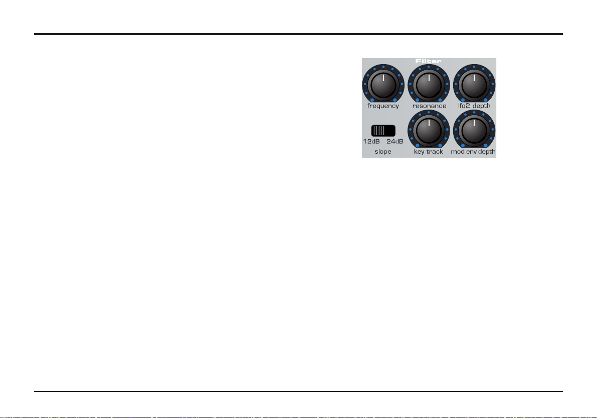
Filter
The Filter is a Low Pass type. As the frequency knob is adjusted
anticlockwise, harmonics are gradually removed from the sound.
When almost closed, only the fundamental frequency remains.
Fully closed and no sound at all passes. This type of Filter is
musically the most useful, especially for bass sounds.
Cut off Switch
Controls how drastically the frequencies above the Cut off point
are removed from the sound. In the 12dB position, the Cut off
slope is gentle so higher harmonics are not attenuated (reduced
in volume) as sharply as they are when in the 24dB position.
Frequency ( Overdrive ) Knob
This knob is dual function, When the FUNCTION select switch is
set to NORMAL it controls the basic Cut off frequency of the filter. If set fully clockwise and the filter is wide open allowing all
frequencies (harmonics) produced by the Oscillators to sound.
As the knob is turned anticlockwise, the filter closes, cutting out
harmonics, starting with the highest, then increasingly lower ones
until only the fundamental or nothing at all is allowed to sound
(fully anticlockwise).
If there is silence when the VOLUME knob is turned up, it is most
likely that the Filter is fully closed. Turn the Frequency knob
clockwise to open the filter.
When the FUNCTION select switch is set to SHIFT, this knob
controls the Filter OVERDRIVE. Used in large amounts it will
have the effect of making the sound richer and slightly distorted.
Main features and operation
Page 23

21
Filter
many of the classic Filters such as the Moog type, Oberheim
type and Roland TB303* type.
If the A-Station produces a high pitched whistling sound, it is
probably due to this knob is being adjusted too far clockwise. If
this self-oscillating effect is not desired, keep the Resonance
control away from the extreme clockwise setting. Increasing the
Resonance is very good for bringing out modulation (movement
or change) in the filter Cut off frequency, such as in Acid bass
lines and other very edgy sounds.
K’YBD Track Knob
Controls the amount of change to the filter Cut off (set by the
Frequency knob) by the pitch of the note played. Set fully anticlockwise and there is no change to the filter Cut off frequency.
With clockwise movement there will be an increasing amount of
modulation. The filter will be opened more as higher notes are
played on the keyboard. This control is used to define how the
timbre of a sound changes over the keyboard. At the 10 position the filter tracks the pitch changes in a 1 to 1 ratio.
Mod Env Knob
Controls the amount of change to the filter Cut off (set by the
Frequency knob) by the Modulation Envelope. In its central
position there is no change to the filter Cut off frequency.
Adjusting the knob anticlockwise from centre will introduce an
increasing amount of negative modulation. The filter will close
as the MOD ENV runs through its cycle. Adjusting the knob
clockwise from centre will introduce an increasing amount of
positive modulaton. The filter will be opened by the MOD ENV.
LFO 2 Depth Knob
Controls the amount of change to the filter Cut off (set by the
Frequency knob) by LFO 2. In its central position there is no
change to the filter Cut off frequency. Adjusting the knob anticlockwise from centre will introduce an increasing amount of
negative modulation. The filter will close and open in time with
LFO2 (this creates the popular wow wow effect).
Adjusting the knob clockwise from centre will introduce an
increasing amount of positive modulaton. The filter will open
and close in time with LFO 2.
NOTE : An external audio signal such as a microphone, guitar
or CD player may be processed by the filter and effects. Refer
to pages 50, 54 and 55 in the Advanced Features Chapter for
more details on setting up this feature.
*TB303 is a trademark of the Roland corporation of Japan
Main features and operation
Page 24
Main features and operation 22
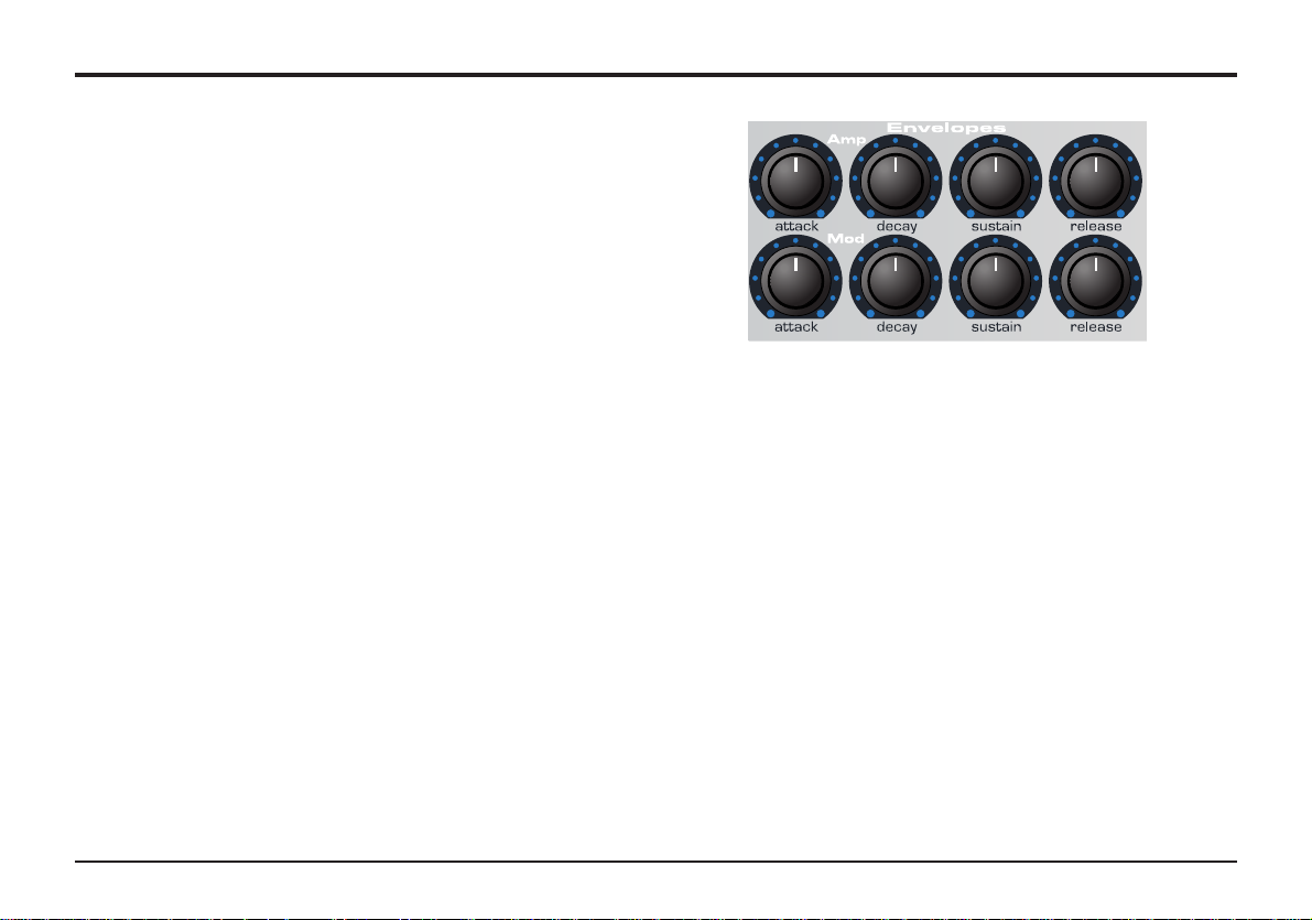
Amp and Mod Envelopes
Attack Knob
Sets how quickly the envelope rises to its maximum level when
a note is struck. Fully anticlockwise and this rise time or slope
is very fast, less than half a thousanth of a second (instantaneous to the ear) increasing exponentially to twenty seconds
when fully clockwise. To shorten attack times turn this knob
anticlockwise and to lengthen attack times turn this knob clockwise.
NOTE: When the attack time is set to Zero the instantaneous
rise time of the Envelope may produce audible ‘clicks’. This is
not a faulty condition and may be useful for the creation of certain sounds. If this is undesirable, increase the Attack time until
the clicks are inaudible.
Decay Knob
Sets how quickly the envelope falls to a sustain level after the
maximum level has been reached. Fully anticlockwise and this
time is about one thousanth of a second (still instantaneous to
the ear ) increasing exponentially to twenty seconds when fully
clockwise.To shorten decay times turn this knob anticlockwise
and to lengthen decay times turn this knob clockwise.
Sustain Knob
Sets the level at which the envelope remains following the
Decay phase, only while a key is being held on a controller keyboard (or there is a Midi note on command present). Fully anticlockwise and the envelope will decay to zero without being
interrupted. As the knob is turned clockwise, the sustain level
increases until, when fully clockwise, the sustain level is at
maximum.
Release Knob
Sets how quickly the envelope falls from the sustain level to
zero once the note has been released. Fully anticlockwise this
time is about one thousanth of a second (instantaneous to the
ear) increasing exponentially to twenty seconds when fully
clockwise.To shorten release times turn this knob anticlockwise
and to lengthen release times turn this knob clockwise.
Amp and Mod Envelopes
The Envelopes are used to shape the sound throughout its
duration. The AMP Envelope determines the volume of the
sound with respect to its duration.
The MOD Envelope may be used to control other sound elements of the synthesizer throughout the duration of the sound.
It can control Pulse Width, Filter frequency and Oscillator Pitch.
Page 25
Main features and operation23
LFOs
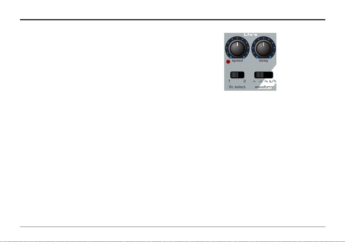
LFOs
There are two LFOs - Low Frequency Oscillators - available.
These produce regular electronic variations which are too low
to be heard when converted into audio vibrations. They can be
used to modify various elements of the sound, producing regular changes in pitch (vibrato), pulse width or filter Cut off.
LFO Select Switch
Selects which LFO the Speed, Delay and waveform controls
relate to. Select position 1 for LFO 1 and 2 for LFO 2.
Speed Knob
Controls the speed of the low frequency Oscillations. An LED
directly below the knob indicates the speed. Faster speeds are
set by turning the knob clockwise. These are suitable for vibrato
and tremolo effects. Slower speeds are more appropriate for
Pulse Width changes or special effects.
Delay Knob
Controls how long after the note is struck the selected LFO
begins to take effect. Fully anticlockwise and the selected LFO
effect will begin immediately. Turning clockwise it will introduce
a time delay before the LFO effect can be heard. This is particularly useful for delayed vibrato effects.
Shape - Switch
Selects the waveform shape for the selected LFO.
S/H - Sample & Hold. At a regular interval (governed by the
Speed knob), the level of the LFO jumps to a new random level
and stays there until the next jump. This creates a rhythmic
effect particularly if routed to the Filter Cut off. Routing this to
pitch gives a less musical result, but is useful for computer or
machinery sound effects.
TRI -Triangle waveform gives the smoothest continuous change
in level to the LFO. When routed to pitch, it introduces vibrato
or a siren effect dependent of its speed setting. When routed to
Filter Cut off, a Wow Wow effect results.
SAW - Sawtooth waveform generates a falling level which then
jumps back up to full level. Routed to the Filter Cut off, it produces a rhythmic pulse effect. Routing it to pitch produces siren
type sounds.
SQR - Square waveform changes level instantly from minimum
to maximum. This waveform is useful for trills and computer
game effects.
Page 26

Advanced features 24
Effects - Delay
This chapter describes how to use the advanced features of the
Effects, Arpeggiator, Synchronization, Triggering and the
Utilities.
Effects
The A-Station features a powerful effects processor. Used in a
creative fashion, it can greatly enhance a sound.
Delay Effect
The comprehensive Delay effects processor has many programmable parameters. These may be edited to create the
desired delay effect for a particular sound and saved with the
sound.
Delay Level
Sets how much of the delayed or echoed sound can be heard.
Delay Time
Controls the amount of time it takes for the delayed signal to be
heard after the original signal.
Delay Feedback Amount
Controls how much of the delayed signal is fed back into the
delay input. No feedback produces a slapback echo effect, just
one delayed sound with no repeats. Small amounts of feedback
produce repeated sounds resulting in a multiple echo effect.
Large amounts of feedback produces infinite echoes.
Delay Sync
The time of the Delay repeats can be synchronized to the
tempo of a song. The standard synchronization method is to
use a MIDI clock as a master timer (See page 26). This may be
used to lock the repeats in time with a range of musical timings
(See table on page 27).
Delay Stereo Width
Sets the Stereo spread between the long and short Delay
times. With a width setting of zero, both delays appear in the
middle of the stereo field (Mono). At maximum width setting, the
longer delay will appear on one output and the shorter on the
other, producing a dramatic stereo effect.
Delay Ratio
Automatically adjusts the ratio of the longest delay time and the
shorter delay time into timings that are musically useful.
(See Delay ratio table on page 26 for timing).
Wheel Level
Sets how much the movement of the Modulation wheel on a
Midi controller keyboard will introduce the delay effect.
Page 27

25
Advanced features
Effects - Delay
To access the Effects processor and other menus, the FUNCTION switch in the master control area must be set to SHIFT
(right hand position).
Instead of numerically selecting programs, the keypad accesses Menus as described by the legends below each key. For
example KEY 1 accesses the DELAY effects Menu, KEY 5
accesses the VOCODER effects Menu etc.
Operation of Menus
In SHIFT mode, each key therefore has a menu associated
with it and for ease, the contents of the menus are presented
in this manual in the form of a table. The first press of the
specific button enters the first level of the menu. Subsequent
key presses select a new item in the menu until the final one
is reached. A further press loops back to the first item (See
the Delay table menu opposite as an example).
A previous item in the Menu may be selected by pressing the
AUDITION button. This allows for easy navigation, both backwards and forwards in the menus. NOTE: The Audition button
only behaves like this when the FUNCTION button is in the
SHIFT mode.
Adding a Delay effect to a sound
Ensure the function switch is set to SHIFT. Press KEY 1 and
the display shows d L with an alternating value. Turn the
PORTA/DATA knob clockwise.
Depending on the settings of the other parameters in the
delay menu, a delay effect will be heard.
Note: As long as the function switch is set to shift, the display
will alternate as in the menu table. To return to displaying and
selecting a program, set the switch back to normal mode.
Key 1 Function Alternating LED Display
1st Press Delay Level d L 0 - 27.
2nd Delay Time d t 0 - 27.
3rd Delay Feedback d F 64. - 63
4th Delay Sync d y oF - 2b
5th Delay Stereo Width d S 0 - 27.
6th Delay Ratio d r 11 - 14
7th Delay Wheel Level d u 0 - 27.
8th
Delay Menu
Page 28

Advanced features
Delay Synchronisation
A very pleasing audio effect may be heard when the Delay time
is synchronized to the tempo of musical piece. The table on the
following page describes the musical timings available.
Setting up a synchronized delay effect using midi clock
sync sent from an external sequencer.
Press the MODE SELECT button until the UTILITY LED is lit.
Repeatedly press KEY 0 until the display shows C S (Clock
Sync) and an alternating value. Set to e (external) by turning
the PORTA/DATA knob. The tempo that the synchronization will
lock to will now be dictated by the MIDI clock being sent by an
external sequencer.
NOTE: When set to
i (internal) the Arpeggiator Rate (set in the
Arpeggiator Menu) will be the master tempo control.
Check that the sequencer is sending MIDI clock events, and
play a previously recorded sequence.
Return to PROGRAM MODE (Press the MODE SELECT until
the PROGRAM LED is lit).
Ensure the function switch is set to SHIFT. Turn the PORTA
/DATA knob clockwise so that the delay effect may be heard.
Repeatedly press KEY 1 until the display shows d y - delay
sync value. Turn the PORTA/DATA knob to experiment with different lengths of delay. The repeats will now be in time with the
musical piece, the repeat time being determined by the synchronization value.
Changing the Delay ratio
There are thirteen musically useful Delay ratios available.
Ensure the function switch is set to SHIFT. Repeatedly press
KEY 1 until the display shows d r - delay ratio value.
Use the PORTA/DATA knob to select the most suitable ratio. A
Simple equal 1 to 1 ratio is the first entry in the table. This setting sends a delay of equal time to the left and right output
channels. The number in the left column of the table indicates
the ratio of the delay time that will be in the left channel versus
the number in the right column.
For example, if a delay of twice the
time is required in the left channel
compared to the right, select the 2 1
option. The final 1 0 and 0 1 options
will result in no delay being in the
channel indicated by the 0.
26
Effects - Delay
Delay Ratio Table
Left Right
11
43
34
32
23
21
12
31
13
41
14
10
01
Page 29

27
Effects - Delay
Advanced features
Five different effects use this table to determine the musical time synchronized to. For example, to Pan the sound to the left for 1
Bar and then to the right for 1 Bar select option 1 b - 1 Bar. To have a Delay repeat every crotchet (quarter note) select 4.
Delay, Panning, Chorus, Arpeggiator and LFO's
Synchronisation to MIDI Clock Table
Display MIDI Clocks Synchronised to:- Display MIDI Clocks Synchronised to:o F - Free running 1 d 144 1.5 Bars
3 t 2 32nd Triplet 2 b 192 2 Bars
3 2 3 32nd 4 t 256 4 Bar Triplet
6 t 4 16th Triplet 3 b 288 3 Bars
1 6 6 16th 5 t 320 5 Bar Triplet
8 t 8 8th Triplet 4 b 384 4 Bars
6 d 9 16th Dotted 3 d 432 4.5 Bars
8 12 8th 7 t 448 7 Bar Triplet
4 t 16 4th Triplet 5 b 480 5 Bars
8 d 18 8th Dotted 8 t 512 8 Bar Triplet
4 24 4th 6 b 576 6 Bars
2 t 32 2nd Triplet 7 b 672 7 Bars
4 d 36 4th Dotted 5 d 720 7.5 Bars
2 48 2nd 8 b 768 8 Bars
1 t 64 1 Bar Triplet 9 b 864 9 Bars
2 d 72 2nd Dotted 7 d 1008 10.5 Bars
1 b 96 1 Bar 1 2 1152 12 Bars
2 t 128 2 Bar Triplet
ENGLISH
Page 30

28Advanced features
The Reverb Effect is an electronic simulation of a room or building that is acoustically reflective.
When a sound is made in a room or large building, there are
sound reflections from all directions. When a Reverb effect is
added, it is these reflections of the sound that are being added.
Adding a Reverb effect to a sound
Ensure the function switch is set to SHIFT. Press KEY 2 and
the display will show r L. Turn the PORTA/DATA knob clockwise. A Reverb effect will be heard. The Reverb menu table
opposite lists the parameters that may be edited for the Reverb
processor.
Reverb type
Different types of rooms and halls have different acoustics,
therefore different Reverb characteristics. The Reverb
processor features six different Reverb types. These range
from a small room to a large hall.
Changing the Type of Reverb
Ensure the function switch is set to SHIFT. Repeatedly press
KEY 2 until the display shows r t. Turn the PORTA/DATA
knob to experiment with different types of Reverb (See table
opposite for display legends).
Reverb Decay Time
This is the time it takes for the Reverb to die away after the
original sound has decayed. Very acoustically reflective rooms
(like those with metal or glass surfaces) tend to have long
decay times and non reflective rooms have short ones.
Reverb Wheel Level
Sets how much movement of the Modulation wheel on a MIDI
controller keyboard will introduce the Reverb effect.
Effects - Reverb
Key 2 Function Alternating LED Display
1st Press Reverb Level r L 0 - 27.
2nd Reverb Type r t S r - L h
3rd Reverb Decay r d 0 - 27.
4th Reverb - Wheel Level r u 0 - 27.
5th
Reverb Menu
Reverb Type Description
E c Echo Chamber
S r Small Room
S h Small Hall
L r Large Room
L h Large Hall
G h Grand Hall
Reverb
Page 31

Advanced features
Chorus
This effect was originally designed to simulate the sound of
many people singing together (hence the name Chorus) in contrast to a single voice. Instrumentally, consider the sound of a
12 string guitar compared to a 6 string guitar.
Chorus is an effect produced by mixing a continuously delayed
version of the audio signal back with the original. The timing of
the delayed version is very small and is controlled by the chorus’s own internal LFO. The characteristic swirling Chorus effect
is the result.
Adding a Chorus effect to a sound
Ensure the function switch is set to SHIFT. Press KEY 3 and
the display will show c L with an alternating value. Turn the
PORTA/DATA knob clockwise. A Chorus effect will be heard.
The Chorus menu table below lists the parameters that may be
edited in for the Chorus processor.
Types of Chorus
Chorus
Chorus provides a stereo effect with a smooth swirling sensation that fattens up sounds and provides a stereo image.
Chorus retains the definition of the effected sound making it
more suitable for basses, organs and percussive sounds.
Phaser
Although referred to as a Chorus type, the Phaser effect is in
fact entirely different. A portion of the audio signal is split off
and phase shifted at certain frequencies. It is then mixed back
with the original signal to generate the characteristic swishing
effect.
Changing the Type of Chorus
Ensure the function switch is set to SHIFT. Repeatedly press
KEY 3 until the display shows c t alternating with either C h Chorus or P h - Phaser. Turn the PORTA/DATA knob to switch
between Chorus and Phaser.
Chorus Speed
Controls how fast the internal LFO is oscillating. A fairly slow
speed is recommended. Higher speeds tend to introduce a
vibrato like quality to the sound.
29
Effects - Chorus - Phaser
Key 3 Function Alternating LED Display
1st Press Chorus Level c L 0 - 27.
2nd Chorus Type c t C h - P h
3rd Chorus Rate c r 0 - 27.
4th Chorus Sync c y oF - 12
5th Chorus Mod Depth c d 0 - 27.
6th Chorus Centre c c 64. - 63
7th Chorus Feedback c F 64. - 63
8th Chorus LFO Initial Pos'n c I o F - R t
9th Chorus Wheel Level c u 0 - 27.
10th
Chorus Menu
Page 32

30Advanced features
Similar to Delay Sync, the Chorus’s own internal LFO may be
synchronized to internal or external MIDI clock tempo - Refer to
Page 26 - Setting up synchronization with MIDI clock.
Chorus Mod Depth
The Chorus has it own LFO which is continuously changing the
delay time. The MOD DEPTH sets how much of the fixed delay
time is being modulated. Large amounts of modulation will produce a more noticeable effect. Moderate amounts are recommended.
Chorus Centre
The Stereo Chorus can be thought of as two continuously variable delays. The delay variations are being controlled by the
LFO. The LFO is constantly moving the two delay amounts
from minimum to maximum. When one delay is at max the
other is at min (hence the stereo effect) The CHORUS CENTRE control moves the middle point between the Min and Max
values. Experiment with this control for the desired effect.
Chorus Feedback
Feedback controls how much of the delayed signal is fed back
to the input of the Chorus generator. The Chorus effect benefits
from low levels of feedback. The Phaser effect requires higher
levels of feedback.
Chorus LFO Initial Position
As well as being able to synchronize to MIDI clock (tempo), the
Chorus LFO may have its initial position set after a specific
MIDI event is received (see page 51 - Global menu options).
The initial positions are shown in the table above. For example,
if the Chorus initial position sync is set to R t , after a MIDI
event the Chorus effect will move from the right to the left.
Chorus Wheel Level
Sets how much movement of the Modulation wheel on a MIDI
controller keyboard will introduce the Chorus effect.
Distortion
Distortion is an effect commonly used by Guitar players, however it is increasingly used in the production of modern Dance
music. The effect gives the sound a hard edged, distorted and
dirty kind of quality.
Adding a Distortion effect to a sound
Ensure the function switch is set to SHIFT Repeatedly press
KEY 4 until the display shows d d (Distortion Drive) and an
alternating value. Turn the PORTA/DATA knob clockwise. The
sound will distort in relation to the setting of the PORTA/DATA
knob.
Effects - Chorus - Phaser - Distortion
Chorus LFO Initial Position Description
o F Off
L t Left
C t Centre
R t Right
Chorus Sync
Page 33

The Distortion and Panning menu table opposite lists the
parameters that may be edited in for the Distortion and Panning
processor.
Distortion Compensation
If distortion is added to a sound it will tend to get louder. In
order to contain or compress the sound back to a level which is
consistent with other programs, use the compensation control.
Distortion Wheel Amount
Determines how much movement of the Modulation wheel on a
MIDI controller keyboard will introduce the Distortion effect.
Panning
The Panning control in the A-Station performs the same function as the Panning knob on a mixing console. It can be used to
position a sound anywhere from left to right in the stereo field.
Changing the Pan Position of a sound
Ensure the function switch is set to SHIFT. Repeatedly press
KEY 4 until the display shows P P and an alternating value.
Turn the PORTA/DATA knob clockwise or anticlockwise to move
the sound across the Stereo field.
Pan Depth
A subsequent press of Key 4 will select Pan Depth. This
parameter determines how much of the Panning effect can be
heard.
Pan Rate
If the Pan Depth is set to a non zero value, the sound will move
from the Left to the Right at at speed determined by the Pan
Rate.
31 Advanced features
Effects - Distortion - Panning
Key 4 Function Alternating LED Display
1st Press Distortion Drive d d 0 - 27.
2nd Distortion Compensation d c 0 - 27.
3rd Distortion Wheel Amt d u 0 - 27.
4th Pan Position P P 64. - 63
5th Pan Depth P d 0 - 27.
6th Pan Rate P r 0 - 27.
7th Pan Sync P Y oF - 12
8th Panning's LFO Initial Position P I oF - R t
9th EQ Amount E A 64. - 63
10th EQ Frequency E F 0 - 27.
13th EQ Depth E d 0 - 27.
11th EQ Rate E r 0 - 27.
12th EQ Sync E y oF - 12
14th EQ LFO Initial Position E k oF - R t
15th
Distortion.. Panning.. Menu
Page 34

Pan Sync
A very pleasing audio effect may be heard when the Panning
effect is synchronized to the tempo of a musical piece. The
table on the Page 27 describes the musical timings available.
Set to o F and the Panning effect will be at the rate determined
by the Speed parameter. Set to any other selection, the
Panning will be in time with the selected musical timing. This
works in similar way to Delay sync (refer to Page 26 for information on setting up this feature).
Panning LFO Initial Position
As well as being able to be synchronized to a MIDI clock
(tempo), the Panning LFO may have it’s initial position set after
a specific MIDI event is received (see page 53- Global menu
options).
The initial positions are shown in the table below. For example,
if the Panning initial position sync is set to R t (Right), after a
MIDI event the sound will begin in the right output audio channel and then move to the left.
EQ Filter
As well as being able to boost low or high frequencies, the final
output EQ Filter may be used to create automatic sweeps of
EQ and filtering. It may be synchronized to tempo and locked to
musical timings from 32nd triplets through to several bars.
EQ Amount
An EQ amount control is provided to give the sound a boost or
cut at any chosen frequency. Positive amounts boost the volume of frequencies above the FREQUENCY POINT (see next
page) and cut the volume of frequencies below it. Negative
settings do the opposite. To change the EQ amount, ensure the
function switch is set to SHIFT. Repeatedly press KEY 4 until
the display shows E A and an alternating value. Adjust the
PORTA/DATA knob for the desired boost / cut.
NOTE: The settings of the EQ FREQUENCY control will determine where in the spectrum the boost / cut appears. Operate
this control in conjunction with EQ frequency.
Advanced features 32
Effects - Panning - EQ Filter
Panning LFO Initial Position
Description
o F Off
L t Left
C t Centre
R t Right
EQ set to -10 (.10) EQ set to 63
Volume
Boost
Volume
Boost
EQ Frequency Point (50)
EQ Frequency Point (50)
Unchanged volume level
Volume
Cut
Volume
Cut
Page 35

The EQ frequency set point determines where in the sound
spectrum the boost or cut occurs. It may be moved anywhere
from very low frequencies (0 = less than 10Hz) to very high frequencies (127 = above 20,000Hz)
To change the EQ frequency, ensure the function switch is set
to SHIFT. Repeatedly press KEY 4 until the display shows E F
and an alternating value. Adjust the PORTA/DATA knob for the
desired EQ frequency.
EQ Depth
The real power of the EQ filter is the ability to move the EQ frequency set point automatically with the dedicated LFO. This
control dictates how intense the movements are from the LFO.
Any amount of depth will result in EQ changes at the rate determined by the EQ rate control.
To change the depth, ensure the function switch is set to
SHIFT. Repeatedly press KEY 4 until the display shows E d
and an alternating value. Adjust the PORTA/DATA knob for the
desired EQ Depth.
Determines the rate (speed) of the dedicated LFO. This LFO is
able to modulate the EQ frequency (see EQ depth). To change
the rate, ensure the function switch is set to SHIFT. Repeatedly
press KEY 4 until the display shows E r and an alternating
value. Rotate the PORTA/DATA knob clockwise to increase the
rate and anticlockwise to decrease the rate.
EQ Sync
The rate (speed) of the LFO may be locked to the tempo of the
musical piece to allow auto EQ Filtering effects.The table on the
Page 27 describes the musical timings available.
Set to o F and the LFO speed will be at the rate determined by
the EQ RATE (see above). Set to any other selection, the LFO
speed will be in time with the selected musical timing. This
works in similar way to Delay sync (refer to Page 26 for information on setting up this feature).
EQ Initial Position
As well as being able to synchronize to MIDI clock (tempo), the
dedicated LFO used to modulate the depth of the EQ may have
its initial position set after a specific MIDI event is received such
as program change of Start Song (see page 53- Global menu
options).
To change the EQ Initial position, ensure the function switch is
set to SHIFT. Repeatedly press KEY 4 until the display shows
E k and an alternating value. The initial positions are shown in
the table on the following page. For example, if the desired
position is to start moving upwards then set to L o (Low). After
a MIDI event the LFO wave will start to climb from this low
Advanced features33
Effects - EQ Filter
EQ Frequency set to 5
EQ Frequency set to 50
Volume
Boost
Volume
Boost
EQ Frequency Point
EQ Frequency Point
EQ Amount (-64)
EQ Amount (-64)
Unchanged volume level
Unchanged volume level
Volume
Cut
Volume
Cut
EQ Frequency
EQ Rate
Page 36

position. Set to C E and it climbs from the centre of the waveform.
Using the EQ Filter Effect
One of the most powerful ways to use this effect is to automatically open and close the filter in time with the musical piece.
The easiest way to listen to this effect is to play a sound with
this feature setup. Select a sound (a bright lead or string type
sound is ideal for this example).
For this effect, the filter must be set to mimic a low pass filter
that opens and closes (‘sweeps’ up and down the frequency
spectrum)
Select the EQ FREQUENCY option (page33) and set it to 5.
Select the EQ AMOUNT option (Page 32) and set it to 63.
Play a few notes and listen to the sound. It should be a very
muted bassy sound. This is because the EQ filter is cutting
most of the frequencies above the set point and boosting those
below.
Select the EQ FREQUENCY option again and while playing the
keyboard, adjust the value and notice how the sound becomes
brighter as the value increases and softer as the value
decreases. Set the EQ FREQ back to 5.
Select the EQ DEPTH option (Page 33) and set it to 30.
Select the EQ RATE option and set it to a medium speed.
While playing, notice how the sound automatically becomes
brighter and softer in time with the speed of the LFO (If there is
no effect, select the EQ SYNC option and make sure it is set to
o F). The final step is to synchronize this with the musical
piece. With a sequencer connected and sending MIDI clock
information, (see page 26) set the EQ SYNC to the desired
musical timing (See page 27 for listing of timings available).
Vocoder
Vocoder sounds have recently returned to popularity and are
being used more frequently in modern Pop and Dance music.
In order to hear a Vocoded sound, recall one of the factory preset sounds (Bank 2 259,269 and 279) and experiment by
entering the Vocoder Menu (Press KEY 5 when in SHIFT
mode) and tweaking the settings.
All the factory presets require an external audio input such as a
microphone to be connected to the external Audio Input jack on
the rear panel (See pages 54,55 and 58 for setting up).
To listen to the sound, simultaneously play a connected MIDI
keyboard and talk into the microphone (if another input device
is being used such as a CD player, then ensure this is playing).
The resulting sound will have a Robot or talky like quality to it.
34
Effects - EQ Filter - Vocoder
Advanced features
EQ LFO Initial Position Description
o F Off
L o Low
C E Centre
H i High
Page 37

Assuming a voice is used via a microphone connected to the
external input, the Vocoder superimposes a replica of the
voice’s energy pattern on to the currently selected sound.
The voice signal known as the Modulator is fed to a bank of
band pass filters. Each of these filters, 12 of them in the AStation covers a set band in the audio spectrum from low to
high frequencies.
A program (for example a string sound) is known as the Carrier.
It is routed to another complete set of 12 filters that have the
same frequency band settings as the bank of filters used forthe
voice. Each of the outputs from the 12 band pass filters in the
modulator (voice) bank control the volume of each of filters in
the carrier bank.
It can now be visualized that, when a low frequency (extracted
from the voice by the modulator filter bank) is received by the
carrier bank, it passes the low frequency of the selected sound.
The other frequencies from the voice are treated in the same
way. This process creates the spoken or vocoded effect.
Adding a Vocoder effect to a sound
Ensure the function switch is set to SHIFT. Repeatedly press
KEY 5 until the display shows u d (Vocoder Balance) and an
alternating value. With a microphone or other sound source
connected to the input jack (this being the modulator), play a
note or chord on the connected MIDI keyboard (this being the
carrier). At a setting of 64, a mix of the Modulator and Carrier
will be heard - the Vocoder effect. At a setting of 0 the Carrier
only will be heard and at a setting of 127 the Modulator only.
Sibilance Level
Determines the amount of sibilance there will be in the vocoded
signal. Typically these are the ‘S’ type of sounds in speech.
Adding sibilance gives the Vocoder a more defined sound.
Sibilance Type
Determines if the vocoder uses real sibilance filtered from the
modulator or artificially generates it using noise. Set to h P and
a high pass filter is used to extract the sibilance from the modulator (NOTE: this will allow some of the modulator signal to be
heard). Set to n o and Noise is used to artificially generate sibilance.
Stereo Width
Determines how wide the stereo output of the vocoder will be.
The 12 bands of the Vocoder are panned one by one to the left
and to the right. Increasing the value moves the bands further
away from the centre position.
35
Effects - Vocoder
Advanced features
Key 5 Function Alternating LED Display
1st Press Vocoder Balance u b 0 - 27.
2nd Vocoder Sibilance Level u L 0 - 27.
3rd Vocoder SibilanceType u t h P - n o
4th Vocoder Stereo Width u S 0 - 27.
5th
Vocoder Menu
What is a Vocoder ?
Page 38

Arpeggiator
The Arpeggiator breaks down chords into single notes and
plays them one at a time. For example, if a ‘C’ triad chord is
held, the notes C, E and G will play one by one in sequence.
How the sequence is played is determined by parameters that
may be set up in the Arpeggiator menu.
Adding an Arpeggio to a sound
Ensure the function switch is set to SHIFT. Press KEY 6 and
the display will show A c (Arpeggiator Condition) and an alternating value. Turn the PORTA/DATA knob clockwise until the
display reads o n (No Latch or Keysync). Play a note or chord
on a MIDI controller keyboard and hold the keys down. The
sound will now start repeating in a pattern determined by other
parameters in the Arpeggiator Menu.
Turning the porta/data knob further clockwise will set different
Arpeggiator modes as described in the table above. Adjusting
fully anticlockwise turns the Arpeggiator off - Display shows o F
No Latch or Keysync - o n
The arpeggiator will stop as soon as notes played on a controller keyboard are released. New notes played will not resynchronize the pattern. Experiment by changing modes and playing the keyboard.
No Latch, Keysync On - o K
The Arpeggiator will behave as above, however new notes
played will resynchronize the pattern. This mode is useful for
certain musical styles.
Latched, No Keysync - o L
This is similar to the o n option, however notes will continue to
sound even when keys are released on the controller keyboard.
To stop the sequence a program change must be made, or the
Arp condition set back to option o F
The final option is similar to o K, except that notes will continue
to sound even when keys are released on the controller keyboard. Repeated presses of KEY 6 will move through the
Arpeggiator menu as described in the table opposite.
Arpeggiator Rate
Sets the speed at which the Arpeggiator sweeps through its
patterns. Fully anticlockwise and the Arpeggiator will step
through a sequence at 64 beats per minute (Display shows 64).
Clockwise movement increases speed. The max speed range is
191 b.p.m. indicated by 91.
36Advanced features
Arpeggiator
Arp Condition Description
o F Off
o n On - No Latch or Keysync
o K On - No Latch, Keysync on
o L On - Latched, No Keysync
o b On - Latched and Keysync On
Latched and Keysync on - o b
Page 39

Arpeggiator Range
Set how many octaves the Arpeggiator will sweep through. The
sweep range is selectable from 1 to 4 octaves.
Arpeggiator Gate Time
Sets the gate time or duration of the notes being played by the
Arpeggiator. Small values of gate time produce a Staccato
effect. Large values produce a Legato effect. Anticlockwise and
the gate time is very short, clockwise and the gate time is long.
Arpeggiator Pattern
Determines the type of Pattern the Arpeggiator will use. Six patterns are available from Up to Random. Use the PORTA/DATA
knob to select the desired pattern.
u P - UP The arpeggio starts at the lowest note played and
sweeps up through the notes until it reaches the highest note. It
then starts at the bottom again and repeats the sequence.
d n - DOWN The arpeggio starts at the highest note played
and sweeps down through the notes until it reaches the lowest
note. It then starts at the top again and repeats the sequence.
U d - UP/DOWN The arpeggio starts at the lowest note played
and sweeps up through the notes until it reaches the highest
note. It then sweeps back down. This is useful when playing
three notes in songs with a 3/4 time signature.
u d - UP/DOWN2 The arpeggio starts at the lowest note
played, plays it twice, and sweeps up through the notes until it
reaches the highest note. It then plays the top note again and
sweeps back down.
L p - LAST NOTE PLAYED The arpeggio plays the last note
played in sequence. Once at the end of the notes played it
repeats the sequence.
r d - RANDOM Notes played will be arpeggiated in a random
order.
NOTE: It is possible to control the Arpeggiator Latch On/Off
from an external Computer/Sequencer. Transmit Midi controller
number 64 with a value of 127 to turn the Arpeggiator latch On
and transmit controller number 64 with a value of 0 to turn the
latch Off.
Advanced features37
Arpeggiator
Key 6
Function Alternating LED Display
1st Press Arp Condition A c o F - o b
2nd Arp Rate A r 64 - 91.
3rd Arp Oct Range A o 1 - 4
4th Arp Gate Time A g 0 - 27.
5th Arp Pattern A P u P - r d
6th Arp Sync A y oF - 2b
7th Arp Note Destination A d In - Et - IE - EP
8th
Arpeggiator Menu
Page 40

Arpeggiator Sync
Allows the Arpeggiator to be synchronized with an external
sequencer. A range of synchronization values are available is
shown in the table below.
When a sync interval is selected, the tempo of the Arpeggiator
is controlled by the Arpeggiator Rate setting (page 36) when
MIDI Clock Source is set to i - internal - or by the external
sequencer’s tempo when MIDI Clock Source is set to e - external - See Page 52 for information on setting the Global MIDI
Clock Source.
Arpeggiator Destination
For flexibility, the Arpeggiator output may be routed to a number
of destinations. Setting the Arp destination to In ( Internal)
routes the Arpeggiated notes to the internal sound engine. This
could be considered as the normal mode of operation. There
will be no Arpeggiated notes output from the MIDI out socket
using this setting.
Setting the destination to Et (external) will route the
Arpgeggiated notes ONLY to the MIDI output socket. Please
note: There will be no sound from the A-Station rack's own
sound engine when this option is selected.
Setting the destination to IE (internal and external) will route
Arpgeggiated notes to both the MIDI output socket and the
internal sound engine.
Setting the destination to EP (External and Played) will route
the Arpeggiated notes to the MIDI output socket but in addition
the A-Station sound engine will just play the notes as received
(not arpeggiated) from an external MIDI keyboard or controller
device.
38
Arpeggiator
Advanced features
Arpeggiator Sync to MIDI Clock table
Display MIDI Clocks Synchronised to
o F - Manual Rate
3 t 2 32nd Triplet
3 2 3 32nd
6 t 4 16th Triplet
1 6 6 16th
8 t 8 8th Triplet
6 d 9 16th Dotted
8 12 8th
4 t 16 4th Triplet
8 d 18 8th Dotted
4 24 4th
2 t 32 2nd Triplet
4 d 36 4th Dotted
2 48 2nd
1 t 64 1 Bar Triplet
2 d 72 2nd Dotted
1 b 96 1 Bar
Page 41

39
Arpeggiator
Advanced features
ENGLISH
Page 42

40
Oscillators
Advanced features
To complement the front panel controls in the Oscillator section
there are many other parameters located in the Oscillators
menu - KEY 7
Setting the Oscillators to play in Unison
Unison mode allows more than one voice to be used for each
note played. This effect is useful when a very thick sound is
required. The A-Station allows up to eight voices to sound layered one on top of another when just a single note is played.
To listen to the effect, ensure the function switch is set to
SHIFT. Press KEY 7 and the display shows u n (Unison
Number) and an alternating value. Turn the PORTA/DATA knob
clockwise until the display shows 2. Play a note and listen to
the sound. It will become thicker sounding. Increasing the number of notes to a maximum of 8 will result in very dense sounding textures. NOTE: As voices are used, the polyphony will
reduce, for example using 8 voices in Unison mode will result in
just one note of polyphony!
Unison Detune Amount
Unison Detune Amount is used in conjunction with Unison
mode as described above. When using more than one voice
per note the Unison detune amount sets how much each voice
is detuned relative to the others. Adjust the amount until the
desired effect is heard.
VCO Drift
Controls the amount of tuning drift for the Oscillators. Setting a
modest value, 10 for example will cause each Oscillator to
slowly drift fractionally out of tune. Classic Analogue
Synthesizers were known to gradually go out of tune as the
internal circuits heated up. This helped to give them there own
unique character.
Oscillator Preglide
A Preglide is applied to the pitch of the Oscillators starting at a
pitch determined by the Preglide amount in semitones. Gliding
up from a pitch occurs when the display indicates between .12 -
1 (minus 12 to minus 1 semitones) and gliding down from a
pitch occurs when the display indicates 1 - 12. (plus 1 to plus
12 semitones) The time it takes to complete the Glide is determined by the Portamento time knob on the front panel. The
Preglide is triggered with every note received.
Key 7 Function Alternating LED Display
1st Press Unison u n o F - 8
2nd Unison Detune u d 0 - 27.
3rd VCO Drift d r 0 - 27.
4th Osc 1,2,3 Preglide P g 12. - 12
5th Oscillator Start Phase o P o F - 14
6th Osc 2 - 3 FM Manual Level F L 0 - 27.
7th Osc 2 - 3 FM Env Amt F E 64. - 63
8th FM Env Attack F A 0 - 27.
9th FM Env Decay F d 0 - 27.
10th
Oscillator Menu
Oscillators
Page 43

Oscillator Start Phase
When synthesizing percussive or plucked type sounds, where
there is a lot of detailed waveform information at the beginning
of the sound, it is often useful to have the Oscillator wave start
in exactly the same place every time a key is pressed.
The start phase option allows the precise starting point of the
Oscillator wave to be determined. At zero, the wave will start at
zero Degrees. Each increment on the display shifts the start
point of the wave approximately 24 degrees. The wave will start
at a random phase when set to o F (off).
FM Synthesis.
The next four menu options allow sounds based on FM
(Frequency Modulation) synthesis to be created. Before looking
at the operations of these controls, a little explanation of FM
synthesis follows.
Earlier in this manual, the basics of subtractive synthesis were
introduced. Terms such as harmonics, timbre, waveforms and
oscillators became familiar.
FM Synthesis is the technique of using one waveform to
Frequency Modulate - FM- another to produce a resultant more
harmonically complex waveform.
The following diagram illustrates that the higher the modulation
between the Modulating wave and the Carrier wave, the more
the waveform changes. In this illustration the Oscillators are
producing Sine waves. It is the change in harmonics over time
that makes a sound interesting to our ears. In FM synthesis, an
envelope generator is inserted between the modulator and carrier waveforms so that there is control over of how much of the
frequency modulation is taking place with respect to time.
Adding this envelope constructs the basic FM building block as
illustrated below.
41
Oscillators - FM Synthesis
Advanced features
Modulator Oscillator
Modulator
Envelope modulation = 20
Modulation level = 0
= 30
= 90
Carrier Oscillator
Carrier
Output waveform
Output waveform
Page 44

42Advanced features
Oscillators - FM Synthesis
Referring to the diagram on the last page, it can be seen that
the output waveform begins the same as the carrier, and
becomes more complex (harmonics are added) as the amount
of FM modulation increases via the envelope. It then returns to
a simple wave again as the envelope decays.
The timbre of the Waveform is changing with time. This is the
opposite of subtractive synthesis where a low pass Filter is
used to remove harmonics.
To complete a simple synthesizer, a further envelope is added
to control the output volume.
The complete FM building block is illustrated below.
OSC 2 is able to FM OSC 3 via a dedicated FM envelope. The
diagram below shows in block diagram format how the
A-Station can produce FM sounds.
The easiest way to be totally familiar with FM is to take one of
the factory preset FM sounds, for example Bank 2 - 49 (Sound
249) and modify it.
Setting OSC 2 - 3 manual FM amount
Ensure the function switch is set to SHIFT. Repeatedly press
KEY 7 (Oscillator Menu) until the display shows F L (Osc 2-3
Manual Level) and an alternating value. Whilst playing a note,
adjust the PORTA/DATA knob. Notice that increasing amounts
of modulation level make the sound more metallic.
Programming FM sounds
Modulator
OSC 2
FM Envelope
OSC 3
AMP ENV
Carrier
Envelope used
to control FM
modulation
amount
Envelope used
to control amplitude
Page 45

Advanced features
Setting the OSC 2 - 3 FM Envelope Amount
Many sounds have complex harmonic movements at the start
of the sound. Introducing envelope modulation from an envelope with a fast attack and decay time to control the FM amount
will simulate this fast changing harmonic effect.
Once in the Oscillator Menu (see previous page), a further key
press will enter the OSC 2 - 3 Envelope Amount settings. The
display will show F E and an alternating value. Adjust this value
using the PORTA/DATA knob. Notice how the ‘spit’ at the beginning of the sound may be accentuated. Experiment with
Oscillator 2 pitch using the OCTAVE switch, SEMITONE and
DETUNE knobs.
Adjusting the FM Envelope Attack and Decay times
Assuming the the Oscillator Menu is selected and FM Envelope
Amount was the last selected item, a further key press will
enter the FM envelope attack time options. The display will
show F A and an alternating value. Adjust this value using the
PORTA/DATA knob.
A further press will select the FM envelope decay time options.
The display will show F d and an alternating value. Adjust this
value using the PORTA/DATA knob.
43
Oscillators - FM Synthesis
Page 46

Advanced features
The A-Station will respond to Pitch and Modulation wheel information from a MIDI keyboard. The response is set using the
Wheels Menu - KEY 8.
Setting up a Pitch change when pushing a wheel forward
Press KEY 8 (ensure the function switch is in SHIFT mode) and
the display will show b 1 alternating with a numeric value. The
value indicates how many semi-tones the pitch will change for
Oscillator 1 when moving the pitch wheel.
Adjust the PORTA/DATA knob until the desired number of semitones is displayed. This affects the current program being listened to. Display values 1-12 will result in a higher pitch when
the wheel is pushed forward. Display values -1 - .12 will result
in a lower pitch.
Subsequent key presses of Key 8 will scroll through
the Wheels menu as described in the table opposite.
NOTE: If the current program uses more than one
Oscillator, it is recommended that the bend amount is
set equal for each Oscillator. If chord type effects are
required when moving the pitch wheel, different pitch
bend amounts may be set for each Oscillator.
Changing the Absolute Pitch using the
Modulation Wheel
During performance it may be desirable to drastically
change the pitch of all the Oscillators using the
Modulation Wheel. Repeatedly press KEY 8 (ensure
the function switch is in SHIFT mode) until the display shows P
A alternating with a numeric value. Adjust the PORTA/DATA
knob. A value from -1 to 64. will result in a lower pitch being
generated when the mod wheel is pushed forward. A value
from 01 to 63 will result in a higher pitch being generated when
the mod wheel is pushed forward.
Setting up Vibrato using the Modulation Wheel
During a performance it is often desirable to introduce a Vibrato
effect by pushing the Modulation Wheel forwards or backwards.
A Vibrato effect is simulated by adding a small amount of pitch
modulation to the Oscillators. The A-Station allows modulation
from LFO 1 to alter the pitch of the Oscillators. Repeatedly
press KEY 8 (ensure the function switch is in SHIFT mode)
44
Pitch and Modulation wheels
Key 8 Function Alternating LED Display
1st Press Osc 1 Pitch Bend Amt b 1 12. - 12
2nd Osc 2 Pitch Bend Amt b 2 12. - 12
3rd Osc 3 Pitch Bend Amt b 3 12. - 12
4th Osc 1,2,3 Absolute Pitch Amt P A 64. - 63
5th Osc 1,2,3 Pitch Mod (LFO1) Amt P L 64. - 63
6th Filter Cut Off Absolute Freq Amt F A 64. - 63
7th Filter Cut Off Freq Mod (LFO2) Amt F L 64. - 63
8th Amplifier Level A L 64. - 63
9th
Wheels Menu
Responding to Pitch and Modulation Wheel Data
Page 47

Advanced features
until the display shows P L alternating with a numeric value.
Adjust the PORTA/DATA knob. A positive value (1 - 63) will
introduce a pitch shift in time with LFO 1. If LFO 1 is set to a
sawtooth wave then the pitch will climb , then rapidly return to
the base pitch.
A negative value (-1 - .64) will result in the pitch falling then
rapidly returning to the base pitch. To achieve the vibrato effect,
set the LFO 1 waveform to triangle. Since this waveform is
symetrical, it does not matter if positive or negative modulation
is used. Adjust the speed of the LFO until the vibrato is satisfactory.
Opening or closing the Filter using the Modulation Wheel
The filter Cut off frequency may be raised (opening the filter) or
lowered (closing the filter) directly from the modulation wheel on
a MIDI controller keyboard.
Press KEY 8 (ensure the function switch is in SHIFT mode)
until the display shows F A alternating with a numeric value.
Adjust the PORTA/DATA knob. A positive value (1 - 63) will
open the Filter when the Mod wheel is pushed forward. A negative value (.1 - .64) will close the Filter when the Mod wheel is
pushed forward.
Setting up a Wow WoW effect using the Modulation Wheel.
Sending a small amount of triangle LFO modulation to the Filter
will simulate the popular Wow Wow effect. Repeatedly press
KEY 8 (ensure function switch is in shift mode) until the display
shows F L alternating with a numeric value. Adjust the
PORTA/DATA knob. A positive value (1 - 63) will open the filter
in time with LFO 2 above the basic Cut off frequency. A negative value (-1 - .64) will close the filter in time with LFO 2 below
the basic Cut off frequency.
Controlling the Volume from the Modulation Wheel.
By routing the Modulation wheel to the amplifier, the overall volume of the sound may be controlled.
Repeatedly press KEY 8 (ensure the function switch is in
SHIFT mode) until the display shows A L alternating with a
numeric value. Adjust the PORTA/DATA knob. A positive value
(1 - 63) will increase the volume when the Mod wheel is pushed
forward. A negative value (-1 - .64) will reduce the volume
when the Mod wheel is pushed forward.
45
Pitch and Modulation wheels
Page 48

The A-Station will respond to Aftertouch information from a
MIDI keyboard and Breath Control from from a Breath
Controller. The response to this information can be set using
the Aftertouch, Breath Menu - KEY 9.
Changing absolute pitch using Aftertouch or Breath
control
Press KEY 9 (ensure the function switch is in SHIFT mode) the
display shows A P (for Aftertouch adjustment) or with 5 more
key presses b P (for Breath control adjustment) alternating with
a numeric value. Adjust the PORTA/DATA knob. A
value from -1 to .64 will result in a lower pitch being
generated when aftertouch or breath control is
received. A value from 1 to 63 will result in a higher
pitch being generated when Aftertouch or Breath control is received.
Setting up a vibrato effect using Aftertouch or
Breath Control
Repeatedly press KEY 9 (ensure the function switch is
in SHIFT mode) - the display shows A L (for
Aftertouch adjustment) or with 5 more key presses b L
(for Breath control adjustment) alternating with a
numeric value. Adjust the PORTA/DATA knob to a
positive value (1 - 64). This will introduce a pitch shift
in time with LFO 1 raising and lowering the basic pitch
of the note.
Note : Ensure the Waveform of LFO 1 is set to triangle
The filter Cut off frequency may be raised (opening the filter) or
lowered (closing the filter) directly from Aftertouch or Breath
control. Repeatedly press KEY 9 (ensure the function switch is
in SHIFT mode) until the display shows A F (for Aftertouch
adjustment) or with 5 more key presses b F (for Breath control
adjustment) alternating with a numeric value. Adjust the
PORTA/ DATA knob. A positive value (1 - 63) will open the
Filter when Aftertouch or Breath control is received. A negative
value (.1 - 64.) will close the Filter when Aftertouch or Breath
control is received.
Opening or closing the Filter using Aftertouch or Breath
Control
46
Aftertouch and Breath Control
Advanced features
Key 9 Function Alternating LED Display
1st Press
Aftertouch to Osc 1,2,3 Absolute Pitch A P 64. - 63
2nd Aftertouch to Osc 1,2,3 LFO 1 Mod Amt A L 64. - 63
3rd Aftertouch to Filter Absolute Freq A F 64. - 63
4th Aftertouch to Filter LFO 2 Mod Amt A n 64. - 63
5th Aftertouch to Amplifier Level A A 64. - 63
6th Breath to Osc 1,2,3 Absolute Pitch b P 64. - 63
7th Breath to Osc 1,2,3 LFO 1 Mod Amt b L 64. - 63
8th Breath to Filter Absolute Freq b F 64. - 63
9th Breath to Filter LFO 2 Mod Amt b n 64. - 63
10th Breath to Amplifier Level b A 64. - 63
11th
Aftertouch..Breath.. Menu
Responding to Aftertouch and Breath Control Data
Page 49

Advanced features
Setting up a Wow Wow effect using Aftertouch or Breath
Control.
Move the function switch to SHIFT and press KEY 9 four times.
The display shows A n(Aftertouch adjustment) or with five more
presses, b n (Breath control adjustment) alternating with a
numeric value. Adjust the PORTA/DATA knob clockwise to a
positive value (1 - 64). This setting will open and close the filter in time with LFO 2.
Note: Ensure the Waveform of LFO 2 is set to triangle
Setting the Volume of the Amplifier using Aftertouch or
Breath Control.
Repeatedly press KEY 9 (ensure function switch is in shift
mode) until the display shows A A (Aftertouch adjustment) or
b A (Breath control adjustment) alternating with a numeric
value. Adjust the PORTA/DATA knob. A positive value (1 -
63) will increase the output volume of the Amplifier Envelope.
A negative value (-1 - .64) will decrease the output volume of
the Amplifier Envelope.
Note: When Using Aftertouch and Breath control features,
check that the MIDI controller device being used is able to
transmit Aftertouch or Breath control information.
Note: In order to hear the effect of any of these settings, press
a key on the MIDI controller, or blow into the breath controller
while adjusting the parameters.
Velocity, Triggering and Synchronization Control
Powerful synchronization and triggering options are available
through the KEY 0 Menu. The table below illustrates the
options available in the menu.
Responding to velocity information from a Controller
keyboard
The Amplifier Envelope, the Mod Envelope and the FM
Envelope can respond to Velocity information. The response to
this information is set using the first three options in this menu
47
Velocity - Triggering - Synchronization
Key 0 Function Alternating LED Display
1st Press Velocity to Amp Env Level u A 64. - 63
2nd Velocity to Mod Env Level u E 64. - 63
3rd Velocity to FM Env Level u F 64. - 63
4th Voice Mode n n n A - P 2
5th Porta Type P t E L
6th Envelopes Triggering Type E t n E - b E
7th Enable External Triggering E E o F - E d
8th LFO's Delay Triggering L d n L - b L
9th
LFO 1 Lock and Sync Control
L 1 - - - k O
10th
LFO 2 Lock and Sync Control
L 2 - - - k O
11th LFO 1 Midi Clock Sync y 1 o F - 12
12th LFO 2 Midi Clock Sync y 2 o F - 12
13th
Vel..Trig..Sync Menu
Page 50

48Advanced features
Press KEY 0 (ensure the function switch is in SHIFT mode) and
the display will show u A alternating with a numeric value.
Adjust the PORTA/DATA knob. At a setting of zero a soft key
stroke will produce a sound at the same volume as a hard key
stroke. At a maximum positive value (63) soft key strokes will
be much quieter than hard key strokes. At a maximum negative
value (.64) soft key strokes will be much louder than hard key
strokes.
Setting up a sound to make its brightness or pitch respond
to velocity
Repeatedly press KEY 0 (ensure the function switch is in
SHIFT mode) until the display shows u E alternating with a
numeric value. Adjust the PORTA/DATA knob.Turn the FILTER
FREQUENCY knob to a near zero setting or until the sound
almost disappears. Turn the MOD ENV DEPTH knob in the
Filter section to maximum clockwise.
In the Envelopes section, Set the MOD ENV ATTACK and SUSTAIN knob to zero and the DECAY knob to nearly full. While
playing notes on a MIDI Keyboard, Adjust the PORTA/DATA
knob. At a setting of zero there will no effect on the brightness
of the sound.
At maximum positive value (63) soft key strokes will produce a
tone much softer than hard key strokes. At a maximum negative value (.64) soft key strokes will produce a tone much
brighter than than hard key strokes.To affect the pitch, adjust
the MOD ENV knob in the Oscillator section.
Select a factory preset FM sound (such as 209) Repeatedly
press KEY 0 (ensure the function switch is in SHIFT mode) until
the display shows u F alternating with a numeric value. Adjust
the PORTA/DATA knob. Notice how the FM effect at the start of
the sound becomes dependent on how hard the keys are
struck.
Voice Mode
Interpretation of new MIDI notes received is set using the Voice
Mode option in the Triggering menu.
Mono Mode - n A For emulating sounds that are naturally
monophonic, Mono mode is available. In this mode only one
voice is used. When a new note is received, the current voice is
truncated and re-run with the new pitch information.
Autoglide - A G A special mode where, only one voice is used
but there must be a gap in between notes played in order for
both Envelopes to re-trigger. Overlapping notes will not trigger
either Envelope. If Portamento is applied to the sound, it will
only be active when notes are overlapped. This mode allows
TB303* type sounds to be easily programmed.
Poly 1 Mode - P1 A new voice is allocated to every new note
received even if a voice is already active at the same pitch.
This is the standard polyphonic mode and is how most modern
synthesizers allocate voices.
Poly 2 Mode - P 2 When a new note is received, any active
voices at the same pitch will be soft triggered (re-used). This is
how many vintage 6 or 8 voice analogue synthesizers allocated
voices.
Velocity - Triggering - Synchronisation
Setting up a sound to make its volume respond to velocity
Adjusting the Velocity Response of the FM Envelope
Page 51

Advanced features
Changing the Voice Mode
Repeatedly press KEY 0 (ensure the function switch is in
SHIFT mode) until the display shows n n and an alternating
value. The table above illustrates the modes according to the
letters displayed. Use the PORTA/DATA knob to change the
mode.
Portamento Type
When PORTAMENTO is applied to a sound, the slow change in
pitch from one note to the next may be at a linear or exponential rate. Experimentation with this parameter is recommend for
different playing styles. To change the type, repeatedly press
KEY 0 (ensure function switch is in shift mode) until the display
shows P t alternating with either E or L. Use the PORTA/DATA
knob to change the mode.
Envelope Triggering Types (Mono mode only)
When the Voice mode is set to any of the Mono options, different envelope triggering options are available for legato playing
styles (notes overlapping). When the first note of a musical
phrase is played, it might be desirable to have both the
Amplifier and Filter envelopes trigger. For the remaining legato
notes,just the filter envelope re-triggering would create the
effect of the phrase becoming quieter and quieter.
Changing the Envelope Triggering Type (Mono mode only)
Repeatedly press KEY 0 (ensure function switch is in shift
mode) until the display shows E t and an alternating value. The
table below illustrates the modes according to the letters displayed. Use the PORTA/DATA knob to change the mode.
Envelope Auto Triggering from External Audio Input
The external audio triggering menu option determines how the
external audio signal is processed. To change the settings,
repeatedly press KEY 0 (ensure function switch is in shift
mode) until the display shows E E and an alternating value.
Rotate the PORTA/DATA knob until the value changes to the
required selection as shown in the table on the following page.
The option E d will send the signal direct to the effects processor.
49
Velocity - Triggering - Synchronisation
Voice Mode Description
n A Mono No Auto Glide
A G Mono with Autoglide
P 1 Poly 1
P 2 Poly 2
Env's Trig Type Description
n E None
A E Amp Env Only
F E Mod Env and FM Only
b E Amp Env,mod Env & FM Env
Page 52

For more information on setting up and triggering from an external audio input signal, see page 52.
LFO Delay Triggering
When the Voice mode is set to any of the Mono options, different LFO delay settings are available for legato playing styles
(notes overlapping). When the first note of a musical phrase is
played it might be desirable to have an initial delay on LFO 1.
(If LFO is routed to pitch modulation, a vibrato effect would be
introduced after the delay time). For the remaining legato notes,
a non interrupted vibrato might be required.
Changing the LFO Delay Triggering (Mono mode only)
Repeatedly press KEY 0 (ensure function switch is in shift
mode) until the display shows L d and an alternating value. The
table opposite illustrates the options according to the letters displayed. Use the PORTA/DATA knob to change the mode.
LFO1 and LFO2 Locking and Key Sync
Both LFO 1 and LFO 2 may be locked or synchronized to Key
presses.
Locking the LFOs
Each of the eight voices have two LFO’s - sixteen in total. The
eight LFOs designated LFO 1 (one per voice) may be ‘phase’
locked together and similarly the eight LFO’s designated LFO 2
may be locked.
To illustrate this, assume the LFO waveform is a triangle wave
and at a specific moment in time all eight are at the beginning
of a the rising portion of the wave. At a later point in time all will
be at the beginning of the falling portion of the wave. If this
waveform is applied to pitch, when a number of notes are
played simultaneously, the pitch of all the notes will rise and fall
at precisely the same time.
If the LFO is not locked, then each wave will be at a random
position relative to the others. In this pitch modulation example,
the pitch of all the notes will be changing ‘out of synchronization’ with others.
LFO's Delay Trig Type Description
n L None
1 L LFO 1 only
2 L LFO 2 Only
b L Both LFO's
50Advanced features
Velocity - Triggering - Synchronisation
External Audio Trig Description
o F Triggering Disabled
t r Triggering Enabled
F d Ext Audio fed Direct to Effects
Page 53

Advanced features
Imagine a String section of eight violin players. With the LFO
locked and the LFO being used to create a vibrato. All eight
of the string players would have the bow in exactly the same
position. This obviously does not occur in a real string section
and if it did the sound would be very unusual. In reality each
player’s bow would be in a different position which gives the
strings a ‘chorus’ type sound. To simulate the string section the
LFOs would not
be locked.
Key Synchronization.
Each LFO may be restarted every time a key is pressed.
For example, if a siren type sound effect was required, an LFO
using a sawtooth wave would be set to positively modulate
pitch. Each time a new key is pressed the pitch would climb
from the same point rather than being at an undetermined pitch
position.
Changing LFO1 and LFO2 Locking and Key Sync
Repeatedly press KEY 0 (ensure function switch is in shift
mode) until the display shows L 1 (for LFO1) or L 2 ( for LFO 2)
and an alternating symbol. The table opposite illustrates the
options according to the letters displayed. Use the PORTA /
DATA knob to change the mode.
LFO1 and LFO2 Midi Clock Synchronization
Both LFOs may be locked to MIDI Clock. As an example, a
very pleasing audio effect may be achieved when an LFO is
modulating the filter cut off frequency and this is synchronized
to the tempo of amusical piece.
To synchronize an LFO, repeatedly press KEY 0 (ensure the
function switch is in SHIFT mode) until the display shows y 1
(for LFO 1) or y 2 (for LFO 2) and an alternating value. Rotate
the PORTA/DATA knob until the desired musical timing value is
displayed according to the table on Page 27.
This works in a similar way to Delay sync. Refer to Page 26 for
information on how to set this up for use with an external
sequencer or computer.
51
LFO's Lock and Sync Description
- - No Keysync No Lock
k - Keysync'd, No Lock
k o Keysync'd with offset, No Lock
- L No Keysync, Locked
k L Keysync'd, Locked *
k O Keysync'd with offset, Locked
Velocity - Triggering - Synchronization
Page 54

52Advanced features
Utility Mode
General functions that are common to the whole machine rather
than program specific are accessed by the GLOBAL MENU.
To access the GLOBAL menu, UTILITY MODE must be selected. Press the MODE SELECT button until the UTILITY LED is
lit.
Pressing KEY 0 now enters the GLOBAL menu. The functions
available with subsequent key presses are listed in the table
below.
Adjusting the Master Tuning
Ensure the MODE is set to UTILITY - Repeatedly press KEY 0
until the display shows t u (Global Tuning) and an alternating
value.
The A-Station is preset at the factory with the display indicating
0 0. The zero value indicates there is no tuning offset. Playing
the note ‘A’ above middle ‘C’ will produce a pitch of 440Hz.
Turn the PORTA/DATA knob, the value on the display will indicate an offset in cents from this pitch. Negative offsets are displayed with a minus before the numeric value or a dot after.
Setting Local On - Off
The knobs on the A-Station will transmit MIDI controller data
that may be recorded by a sequencer. This feature allows a
sequencer, when in playback mode to send MIDI controller data
which has the effect of adjusting knob values. Although there is
no physical movement of the knobs, the sound will be manipulated in real time according to the controller data values.
NOTE: To prevent a MIDI data conflict arising when knobs
are being adjusted and data being is received from a
sequencer when there is a complete MIDI loop, LOCAL
OFFf must be selected. If there is no MIDI loop LOCAL ON
must be selected
See page 58 for a typical MIDI connection diagram where there
is a loop and setting to LOCAL OFF would apply.
Ensure the MODE is set to UTILITY - Repeatedly press KEY 0
until the display shows L o (Local ) and an alternating value.
Turn the PORTA/DATA knob, to switch between off and on (o F
and o n).
Utility Mode - Global Menu - Master tuning - Local On / Off
Key 0 Function Alternating LED Display
1st Press Tuning - Cents t u 50. - 50
2nd Local L o of - on
3th Midi Clock Source c S i - e
4th Midi Clock Inspector c i - - 96
5th Clock Sync Type S t PC - SS
6th Pot Display Persistance P P 0 - 27.
7th Velocity Curve u c S t - H d
8th Menu Initial Display i d oF - on
9th Input Sensitivity i S Lo - HI
10th Input Trim i t 10. - 20
11th Input Trig Sensitivity i L 0 - 27.
12th
Utility Mode Global Menu
Page 55

The A-Station requires a master timing clock in order to determine the tempo (rate) of the arpeggiator and to provide a time
base for synchronization to other musical timings. This clock
may be derived internally or received from an external device
that is able to send a master timing clock (This is often known
as a MIDI clock).
If synchronization to external events is not required, then setting this Master clock source to Internal is recommended. Set to
internal, the Arpeggiator Rate (adjustable in the Arpeggiator
Menu) sets the speed of the clock in Beats per Minute (B.P.M.).
To change from internal to external clock, press the MODE
SELECT button until the UTILITY LED is lit. Repeatedly press
KEY 0 until the display shows c S (Clock Sync) and an alternating value. Set to e (external) by turning the PORTA/DATA knob.
The tempo that the Arpeggiator and any synchronisation will
lock to will now be dictated by the MIDI clock being sent by an
external sequencer. To change back to Internal, turn the
PORTA/DATA knob until the display indicates i.
MIDI Clock Synchronization Type
If the MIDI clock source is set to external, a clock synchronization type may be selected. This allows a MIDI event, either first
note played after program change or MIDI Start Song Message
to synchronize the Panning, EQ Filter and Chorus LFO’s. They
may have their start position locked in time with the musical
piece for stunning effects.
To change the clock sync type, press the MODE SELECT button until the UTILITY LED is lit. Repeatedly press KEY 0 until
the display shows S t (Sync Type) and an alternating value. Set
to P C for first note after Program Change or S S for Start Song
Message by turning the PORTA/DATA knob.
MIDI Clock Inspector
It is possible to see if an external device is sending a MIDI
clock by using the MIDI Clock inspector. This is useful for trouble shooting. Press the MODE SELECT button until the UTILITY LED is lit. Repeatedly press KEY 0 until the display shows
C i (Clock Inspector) If an external clock is being received, the
display will indicate the tempo of the external clock. If not
- -
will be displayed.
Knob value display time
In normal operation, when the front panel knobs are adjusted,
the LED display momentarily switches from displaying the
Program number, to displaying the value of the parameter being
adjusted. It then switches back to displaying the Program number. The length of time that the adjusted parameter is displayed
before switching back, may be set in this menu option.
Press the MODE SELECT button until the UTILITY LED is lit.
53
Global Menu - Midi Clock Source/Sync type/Inspector - Display time
Advanced features
Clock Sync Type Description
P C First note after program chg
S S Midi Start Song Msg
MIDI Clock Source
Page 56

Repeatedly press KEY 0 until the display shows P P (Potentiometer Persistence). To increase the display time of the adjusted value, turn the PORTA/DATA knob clockwise, to reduce the
time, turn anticlockwise. A setting of 0 0 will inhibit the display
from showing parameter values when knobs are adjusted.
Velocity Curve
The response to MIDI velocity information from an external
device such as a MIDI controller keyboard or a sequencer may
be set using this option. Press the MODE SELECT button until
the UTILITY LED is lit. Repeatedly press KEY 0 until the display
shows u C (Velocity Curve)and an alternating value.
A setting of S t (Soft) indicates that smaller changes in velocity
, a lighter playing style, is required to create a large change in
response to velocity, be it volume or any other parameter that
velocity routed to. A setting of H d (Hard) indicates that higher
changes in velocity - a much harder playing style, is required to
create large changes in response to velocity.
Operation of the Display Menus
The display menus (including this one) can operate in two different modes. The first mode (factory default setting) specifies
that each time a new menu key is pressed, the first item in the
menu list is always selected. For example pressing KEY 2 Reverb, after KEY 3 Chorus, will result in always selecting
Reverb level. The second mode specifies that the last used
item in the menu list for a KEY is selected. For example, if
Reverb Decay is being adjusted - KEY 2, and the Chorus button is pressed - KEY 3, a subsequent press of KEY 2 will
result in Reverb Decay being the menu item selected.
Press the MODE SELECT button until the UTILITY LED is lit.
Repeatedly press KEY 0 until the display shows i d (Initial
Display) and an alternating value. Adjust the PORTA/DATA
knob. The display will switch from o F (first mode) to o n
(second mode).
Using the External Audio Input
In order to use an external audio input, the A-Station must be
set up to correctly to respond to the level (amplitude) of the
incoming signal. Since the levels of these signals can vary substantially, the Global menu option, Input Sensitivity and Input
Trim must be adjusted for optimum performance.This will minimize distortion and noise.
Adjusting the Input Sensitivity of the External Audio In
Connect the input device to the rear panel jack labeled INPUT.
Repeatedly press the MODE SELECT button until the UTILITY
LED is lit. Repeatedly press KEY 0 until the display shows i S
(Input sensitivity) and an alternating value. When connecting
devices such as CD’s Turntables, Mixing desks or other line
level equipment, set the sensitivity to L o. Set to H I for devices
such as Guitars or Microphones.
54
Global Menu - Velocity Curve - Display Menus - External Audio Input
Advanced features
Velocity Curve Description
S t Soft
H d Hard
Page 57

Once set, play (or talk into the microphone), the column of
LEDs to the right of the display should now respond to the level
of the signal. It is likely that they will either all illuminate or just
the lowest one or two in the column. The ‘Input Trim’ must now
be set to optimize performance.
Adjusting the AudioTrim for External Signals
After Input Sensitivity is set - see above, the sensitivity must be
‘trimmed’ for best performance. Ensure the MODE
is set to UTILITY. Repeatedly press KEY 0 until the display
shows i t (Input Trim) and an alternating value. Whilst the input
signal is present adjust the PORTA/DATA knob until the all the
LEDs except the very top one - PROGRAM - frequently light.
The sensitivity level is now set correctly.
In order to hear the external signal through the effects processor or to make the signal trigger sounds, the current PROGRAM selected has to have external audio enabled (see page
50).
Setting an External Audio Signal to Trigger the Envelopes
Once the input sensitivity has been set for the input device (see
above) set the SOURCE switch in the Mixer section on the front
panel to EXT and turn up the LEVEL. Before adjusting the
threshold (how loud the external signal has to be before it trig-
gers the envelopes ) check that the specific program has its
triggering options enabled for external audio.(Set Triggering
Option E E to E n in the KEY 0 Vel..Trig..Sync Menu.. (see
page 49)
Adjusting the Audio Input Auto triggering Sensitivity
Ensure the MODE is set to UTILITY. Repeatedly press KEY 0
until the display shows i L (Input Trigger Level) While playing
the external audio input device (or talking into the microphone).
adjust the PORTA/DATA knob until the external audio signal is
heard at the output. If there is no output, check that the
Envelope controls are set to sensible levels and that the Filter
FREQUENCY is fully clockwise.
If any of the Oscillator volumes are turned up (Mixer section) a
default middle ‘C’ note will be heard even when there is no
MIDI input. If this is undesirable, then reduce the volumes of all
the Oscillators.
Using External Audio Direct to Effects
The external audio signal may be fed directly to the effects
bypassing the Mixer, Filter and Envelopes. Once the input sensitivity has been set for the input device (see previous page) set
the SOURCE switch in the Mixer section on the front panel to
EXT and turn up the LEVEL. Set the Triggering Option E E to
F d in the KEY 0 Vel, Trig, Sync Menu, (see page 50) The
external signal should now be heard at the outputs. It may now
be processed by all the effects including the EQ Filter.
55
Global Menu - External Audio Input
Advanced features
Input Sensitivity Description
L o Low Gain
H I High Gain
Page 58

56
Utility Mode - Backing up sounds - Restoring factory preset sounds
Advanced features
Sending (Backing Up) sounds to an external device
Remaining KEYS in the UTILITY MENU are used for sending
PROGRAMS (backing up) to external storage devices and for
restoring factory preset programs. Press the MODE SELECT
button until the UTILITY LED is lit.
Referring to the table above, each button corresponds to the
operation as listed. The action of pressing the button initiates
the data transmission.
The data is sent in a standard format which is known as MIDI
System Exclusive. This is often known by its shorthand name
SYSEX. Before any sending data, check that the device (usually a sequencer) is able to receive this type of data. To send
Bank 3 Programs, for example, press KEY 3. The display will
flash b 3 while data transmission is in progress.
Restoring a single factory preset sound
Select PROGRAM mode and enter the destination location for
the single factory preset to be restored to. Select UTILITY
mode. Press Key 9, the display will indicate 1 P (restore single
program) Press the + KEY once, the display will start flashing
the selected destination program number as a prompt. A second press of the + KEY actually restores the factory preset program.
NOTE: If at any time it is necessary to abandon the restore
process, then press the MODE select button.
Restoring a Bank of factory preset sounds
Select PROGRAM mode and enter the destination bank for the
bank of factory presets to be restored to. (for example, if the
sounds in bank 2 are required to be over written, select ANY
Key 9 Function LED Display
1st Press Restore One Program 1 P
2nd Restore 100 Sounds from Bank 1 B 1
3th Restore 100 Sounds from Bank 2 B 2
4th
Utility Mode Restore Menu
Key Number Function
0 Global Menu
1 Send Bank 1 Programs
2 Send Bank 2 Programs
3 Send Bank 3 Programs
4 Send Bank 4 Programs
5
Not Used at Present
6 Send All Banks
7 Send current Sound
8 Send Global
9 Restore Menu
Util Mode
Page 59

57
Utility Mode - Receiving sounds from an external device
Advanced features
sound in bank2) Go to UTILITY mode. Press Key 9 twice, the
display will indicate B 1 (restore bank 1) Each subsequent
press will move to the next bank, bank 2. Press the + KEY
once, the display will start flashing the selected destination
bank number as a prompt.
A second press of the + KEY and the two dots in the display
will also flash. The third press actually initiates the restore
process. Finally the two dots only will flash and the MODE will
change back to PROGRAM mode.
NOTE: If at any time it is necessary to abandon the restore
process, then press the MODE select button.
Receiving a single sound from an external device (or other
A-Station)
Sounds (using MIDI SYSEX transfers) may be sent to the unit
at any time from a sequencer/computer or other A-Station.
When a sound is received the display will alternate with - - and
the current program number. The received sound will be heard
when a note is played. If the sound is to be kept it must be
saved in the normal way.
Receiving a bank of sounds from an external device (or
other A-Station)
As long as the Memory protect is switch off (see page 6) banks
of sounds (using MIDI SYSEX transfers) may be sent to the unit
at any time from a sequencer/computer or other A-Station. The
bank of sounds will be written into the bank of the currently
selected program. For example, if sound 321 is selected, the
incoming bank will be placed in bank 3. To acknowledge reception of incoming data, the display will show the incoming program numbers while data is being received.
Page 60

58
Connection Diagram
Advanced features
The diagram above illustrates how the A-Station is connected in
a typical MIDI recording setup. It utilises all the Input and Output
features. This setup allows real-time recording of knob movements into a Computer Software/Sequencer since both the MIDI
output of the keyboard and the MIDI output of the A-Station are
connected to the Computer Software/Sequencer.
The Computer Software/Sequencer MUST have at least 2 MIDI
inputs to allow knob movements to be recorded at the same
time as playing the keyboard. If it does not, then a MIDI merge
box must be used to merge the MIDI information from the keyboard and the A-Station into a single stream (Consult the manufacturers user guide for the MIDI merge box for correct connec-
tion). If the Master Keyboard is a Workstation (it has a
Synthesizer built in) set it to Local Off or the equivalent in its
MIDI setup. Turn the Computer Software/Sequencers Soft Thru
(or sometimes called Echo Back) to the On or Enabled position.
Select a track in the Computer Software/Sequencer and assign
it to the MIDI receive channel of the A-Station.
Play the keyboard and an audio output from the A-Station
should be heard through the Headphones/Monitors. Tracks on
the Computer Software/Sequencer that are assigned to the MIDI
channel(s) of the workstation should also trigger sounds in the
workstation.
A-Station must be set
to Local OFF mode
Page 61

59
Notes
Advanced features
Volume Control
The Volume may be overridden by MIDI Volume data. If MIDI
Volume of 0 has been received by the A-Station, no output will
be heard regardless of the position of the volume knob. To
reset the volume, either transmit the relevant MIDI Volume level
or move the Volume knob - this automatically overrides the
MIDI setting.
Responding to MIDI Sustain Pedal On / Off
The A-Station will respond the normal MIDI controller message
for Sustain Pedal On / Off. Connect a sustain pedal to the MIDI
controller keyboard or workstation that is to be used in the system. It is often necessary to check that the polarity of the pedal
is correct for the controller keyboard or workstation that it is to
be used with.
Page 62

A-1
Factory Preset Sounds Listings and Examples
Appendix
No. Name No. Name No. Name No. Name No. Name No. Name No. Name No. Name No. Name No. Name
100 Bass1 110 Bass2 120 Bass3 130 Bass4 140 Bass5 150 Bass6 160 Bass7 170 Bass8 180 Bass9 190 Bass10
101 Hard Lead1 111 Hard Lead2 121 Hard Lead3 131 Hard Lead4 141 Hard Lead5 151 Hard Lead6 161 Hard Lead7 171 Hard Lead8 181 Hard Lead9 191 Hard Lead10
102 Arpeggio1 112 Arpeggio2 122 Arpeggio3 132 Arpeggio4 142 Arpeggio5 152 Arpeggio6 162 Arpeggio7 172 Arpeggio8 182 Arpeggio9 192 Arpeggio10
103 Dance1 113 Dance2 123 Dance3 133 Dance4 143 Dance5 153 Dance6 163 Dance7 173 Dance8 183 Dance9 193 Dance10
104 Pad1 114 Pad2 124 Pad3 134 Pad4 144 Pad5 154 Pad6 164 Pad7 174 Pad8 184 Pad9 194 Pad10
105 Keyboard1 115 Keyboard2 125 Keyboard3 135 Keyboard4 145 Keyboard5 155 Keyboard6 165 Keyboard7 175 Keyboard8 185 Keyboard9 195 Keyboard10
106 Strings1 116 Strings2 126 Strings3 136 Strings4 146 Strings5 156 Strings6 166 Strings7 176 Strings8 186 Strings9 196 Strings10
107 Brass1 117 Brass2 127 Brass3 137 Brass4 147 Brass5 157 Brass6 167 Brass7 177 Brass8 187 Brass9 197 Brass10
108 Organ1 118 Organ2 128 Organ3 138 Organ4 148 Organ5 158 Organ6 168 Organ7 178 Organ8 188 Organ9 198 Organ10
109 Soft Lead1 119 Soft Lead2 129 Soft Lead3 139 Soft Lead4 149 Soft Lead5 159 Soft Lead6 169 Soft Lead7 179 Soft Lead8 189 Soft Lead9 199 Soft Lead10
No. Name No. Name No. Name No. Name No. Name No. Name No. Name No. Name No. Name No. Name
200 Bass11 210 Bass12 220 Bass13 230 Bass14 240 Bass15 250 Bass16 260 Bass17 270 Bass18 280 Bass19 290 Bass20
201 Hard Lead11 211 Hard Lead12 221 Hard Lead13 231 Hard Lead14 241 Hard Lead15 251 Hard Lead16 261 Hard Lead17 271 Hard Lead18 281 Hard Lead19 291 Hard Lead20
202 Arpeggio11 212 Arpeggio12 222 Arpeggio13 232 Arpeggio14 242 Arpeggio15 252 Arpeggio16 262 Arpeggio17 272 Arpeggio18 282 Arpeggio19 292 Arpeggio20
203 Dance11 213 Dance12 223 Dance13 233 Dance14 243 Dance15 253 Dance16 263 Dance17 273 Dance18 283 Dance19 293 Dance20
204 Pad11 214 Pad12 224 Pad13 234 Pad14 244 Pad15 254 Pad16 264 Pad17 274 Pad18 284 Pad19 294 Pad20
205 Keyboard11 215 Keyboard12 225 Keyboard13 235 Keyboard14 245 Keyboard15 255 Keyboard16 265 Keyboard17 275 Keyboard18 285 Keyboard19 295 Keyboard20
206 Trance1 216 Trance2 226 Trance3 236 Trance4 246 Trance5 256 Trance6 266 Trance7 276 Trance8 286 Trance9 296 Trance10
207 Brass11 217 Brass12 227 Brass13 237 Brass14 247 Brass15 257 Brass16 267 Brass17 277 Brass18 287 Brass19 297 Brass20
208 Motion1 218 Motion2 228 Motion3 238 Motion4 248 Motion5 258 SFX1 268 SFX2 278 SFX3 288 SFX4 298 SFX5
209 FM1 219 FM2 229 FM3 239 FM4 249 FM5 259 Vocoder1 269 Vocoder2 279 Vocoder3 289 Ex Aud Trig 299 Ex Aud to FX
Bank 1 - Sounds 100 - 199
Bank 2 - Sounds 200 - 299
Example initialisation Sounds
A few example sounds have been provided that illustate how some of
the feature of the A-Station can be used.
Sound 300 - Double Saw Example 1
The double effect works by making each oscillator produce two waves
for each setting - sine, saw and tri. These are normally in phase and
appear to be one waveform. The phase difference between each of the
two waves for a single oscillator can be independently phase shifted by
adjusting the pulse amount control. The phase can be moved from -180
to 180 degrees.
This can be automated by using an LFO to adjust the phase difference
between the two waves. When a triangle LFO 2 wave is selected, this
will ramp the phase difference of the double waves up and down and
the result is similar to a chorus effect. At moderate to high settings this
sounds much like PWM of a square wave.In this sound only oscillator
1 is used. It is set to a sawtooth wave. The PWM position is set centrally and the PWM position from LFO 2 is set to +30. LFO 2 speed is set
to 65 with the waveform as a tri wave.
Try varying the speed of LFO 2 and the PWM position from LFO 2
amount for different effects.
Sound 301 - Double Saw Example 2
When a sawtooth wave for LFO 2 is selected and used to modulate the
phase difference between the two waves AND the LFO 2 pulse amount
is set to maximum, a complete change in phase occurs between the
double waves from maximum to
minimum (180 to -180 degrees)
during the cycle of 1 period of the LFO. This then repeats immediately
Page 63

from 180 degrees again. This is equivalent to two waves with a constant detune.
In this example only Oscillator 1 is used again. It is set to a sawtooth
wave. The PWM position is set centrally and the PWM position from
LFO 2 is set to +63. The LFO speed is set to 50 with the LFO 2 waveform as a saw wave.
Try varying the LFO speed to adjust the amount of detune between the
double oscillators. Note that settings for the LFO 2 pulse amount that
are not maximum or minimum values will produce clicks in the sound
because the phase difference will be interrupted.
Sound 302 - Oscillator Sync Example
Oscillator 1 can sync Oscillator 2 so that each time Oscillator 1 completes it's cycle it resets the start cycle of Oscillator 2. When listening to
only Oscillator 2 this has a very distinctive sound.
Here the Oscillator 2 level is 100% and Oscillator levels for Oscillators
1&3 are both 0%. Oscillator 1 has no envelope modulation whereas
Oscillator 2 has a mod env depth of 45. The modulation envelope is set
with an attack of 080 and a decay of
100. The sustain and release times for the mod envelope are 000. As
the pitch of Oscillator 1 rises and falls this changes the way the
Oscillator 2 wave is reset.
Try experimenting with the modulation envelope settings, the mod env
depth amount for Oscillator 2 and the Octave / Semitone settings for
Oscillators 1&2.
Sound 303 - Ring Mod Example
Here all the Oscillator levels are set to 000. The Ring Mod level is set
to 100%. The modulation envelope has an attack setting of 035 and a
decay setting of 105. The mod env amount is set to +50 for Oscillator 2
and -40 for Oscillator 1.
Try experimenting with the modulation envelope settings, the mod env
depth amount for Oscillators 1&2 and the octave / semitone settings for
Oscillators 1&2.
Sound 304 - Main Output EQ Filter Example.
The additional main output tempo sync'ed enveloped filter.
This is a powerful eq filter which is at the output stage of the signal path
of the A-Station. This can boost frequencies as well as attenuate them compared the low pass filter which can only attenuate. Positive settings
of the amount control will boost frequencies above the frequency point
and attenuate frequencies below it. Negative settings of the eq amount
will attenuate frequencies above the frequency point and boost frequencies below it.
The key point to this feature is the EQ Depth control. This will use a
dedicated LFO to move the frequency point of the eq. The eq LFO can
be sync'ed to midi clock or to the arpeggiator clock and an eq initial
position can also be set just like for the chorus and pan effects.
This example has been set up for use with an external input. It will work
particularly well with drum loops etc. Try varying the amp envelope controls and the eq level, depth, rate and frequency controls.
A-2
Factory Preset Sounds Listing and Examples
Appendix
Page 64

Operating System version and Upgrading via the Internet
The A-Station uses a special memory device known as “flash”
that contains all of the information that determine how the AStation functions.
This special device can be re-written by sending it a new set of
information using the MIDI input. This set of information is
known as an Operating System and has the format of a MIDI
file. (Often referred to as O/S) From time to time a new O/S
may become available that has new features, or where an
existing feature has been improved.
To check the level of current O/S, apply power to the A-Station.
The version number will be displayed will briefly. For example
1.0 or 1.1
A free download of the latest O/S is available from the Novation
website www.novationmusic.com The O/S is located in the
downloads section within the site.
This manual conforms to Operating System version 1.1
Loading in a new operating system (OS).
1) Make a back up of all data stored in the A-Station to a
sequencer.
From program mode, press the select button twice so that the
utility LED is lit. Connect midi out of the A-Station to midi in of a
sequencer and set the sequencer recording. Press button 6 on
the A-Station keypad to initiate the "all banks" data transfer.
Stop the sequencer recording when the sequencer midi in indicator shows that all midi activity has finished.
2) Verify the back up.
Change a setting in program 100 which can be remembered.
Save the change to the A-Station program 100. Connect the
midi out of the sequencer to the midi in of the A-Station. Play
the back-up file originally recorded back into the A-Station. If
program 100 reverts to the original setting then the back-up
should be ok.
3) Play the OS .mid file into the A-Station
Once downloaded from the website, Import the midi file of the
operating system into a sequencer. While holding the MODE
SELECT down, apply power to the A-Station. 'nu' alternating
with 'os' will be displayed. Release the MODE SELECT button
and then press the demo button.
The machine will be ready to accept the OS midi file, 'se' alternating with 'nd' will be displayed. Play the midi file out of the
sequencer into the A-Station. The LED display will show the
percentage of operating system received. Once complete, the
LED screen will show 'tn' alternating with 'of' (turn off). The AStation will need to be turned off and on again for the new OS
to take effect.
A-3
Operating System upgrading via the Internet
Appendix
Page 65

Oscillators
Waveform Square / Saw / Variable Pulse /
Tri / Sine / Double Saw /
Double Tri / Double Sine
Octave Range Shift -1 / 0 /+1 / +2
Mod Env Depth -100% to +100%
LFO1 Depth -100% to +100%
PWM Source Mod Env / Manual / LFO2
Ring Mod 1 * 2
FM 2 * 3
2 * 3 FM Level 0 – 100%
2 * 3 FM Mod Level 0 – 100%
FM Env Attack Rate 500uS-20 Seconds
FM Env Decay Rate 1mS-20 Seconds
Mixer
Osc 1 - 2 Level Off-Osc1-Osc2
Osc 3 Level 0 – 100%
Noise Level 0 – 100%
FM Level 0 – 100%
External Input Level 0 – 100%
Filter
Frequency 5Hz-24kHz
Resonance 0-Self Oscillation (24dB mode)
Mod Env Depth -100% to +100%
LFO 2 Depth -100% to +100%
Cut Off 0-100%
Keyboard Tracking 0-100%
Overdrive / Q normalise 0-100%
Amplifier and Mod Envelope
V
elocity -100% to +100%
Attack 250uS-20 Seconds
Decay 1mS-20 Seconds
Sustain 0-100%
Release 1mS – 20 Seconds
LF01 and LFO2
Waveform Sample & Hold / Tri / Saw / Squ
Speed 0 Hz – 1Khz
Delay Fade In 0 – 5 Seconds
LFO Sync Internal – MIDI Clock
Arpeggiator
Arpeggiator Speed / Range / Gate Time /
MIDI Clock / Sync / Keysync
Interfacing
MIDI Sockets In / Out / Thru
Audio Input Line Level 1 x Mono 1/4” Jack
Audio Outputs Line Level 2 x Mono 1/4” Jack
Effects
Reverb Level / Echo Chamber, Small Room
Large Room, Small Hall, Large Hall
Grand hall / Decay / Wheel Level
Chorus - Phaser Level / Rate / Type / MIDI
Clock Sync / Feedback / Mod
Depth / Centre / MIDI clock sync inital Position
Wheel Level
Distortion Drive / Compensation / Wheel Level
Panning Position / Mod Depth / Speed / MIDI clock Sync
Initial Position
Delay Depth / Time / Feedback / MIDI
Clock Sync/ Stereo Width / Ratio
/ Wheel Level
Vocoder On –Off / Sibilance Level /
Sibilance Type
EQ / Filter Depth / Freq / Mod Depth / Mod Speed
MIDI clock sync / MIDI clock sync Initial postion
General
Power 9 Volt D.C. 600 mA
Dimensions W=483mm H=44mm D=125mm
Weight 1.6 Kg
A-4
A-Station technical Specification
Appendix
ENGLISH
Page 66

#
MIDI-SSPECIFIED UUSE A-SSTATION UUSE
0 bank msb IGNORED/NOT TRANSMITTED
1 modwheel msb MODWHEEL (receive only)
2 breath msb BREATH CONTROL (receive only)
3 undefined msb ARP PATTERN (0..5 = up, dn, ud1, ud2, order, rand)
4 foot controller msb --5 portamento time msb PORTAMENTO TIME
6 data entry msb USED FOR NRPN DATA VALUES
7 volume msb VOLUME
8 balance msb PREGLIDE SEMITONES *** -12..+12 (0=preglide disabled)
9 undefined msb ARP RATE (64..191 bpm)
10 pan msb PAN POSITION ***
11 expression msb --12 effect control 1 msb NON-SYNC PAN RATE
13 effect control 2 msb SYNC PAN RATE 0..34 (non-sync, 32Triplet..12bars)
14 undefined msb VOCODER STEREO WIDTH
15 undefined msb VOCODER SIBILANCE LEVEL
16 gen. controller 1 msb MODWHEEL DISTORTION ***
17 gen. controller 2 msb DISTORTION COMPENSATION
18 gen. controller 3 msb MODWHEEL DELAY SEND
19 gen. controller 4 msb NON-SYNC DELAY TIME
#
MIDI-SSPECIFIED UUSE A-SSTATION UUSE
20 undefined msb SYNC DELAY TIME 0..19 (non-sync, 32Triplet..2Bars)
21 undefined msb DELAY FEEDBACK
22 undefined msb DELAY STEREO WIDTH
23 undefined msb DELAY RATIO
24 undefined msb MODWHEEL REVERB SEND ***
25 undefined msb REVERB DECAY
26 undefined msb MODWHEEL CHORUS SEND ***
27 undefined msb NON-SYNC CHORUS RATE
28 undefined msb SYNC CHORUS RATE 0..34 (non-sync, 32Triplet..12bars)
29 undefined msb CHORUS FEEDBACK ***
30 undefined msb CHORUS MOD DEPTH
31 undefined msb CHORUS MOD CENTRE POINT
32 bank lsb BANK SELECT 1..4
33 modwheel lsb EQ LEVEL *** (0, 1..63, 64, 65..126,
127 = LP, LPshelf, flat, HPshelf, HP)
34 breath lsb EQ FREQUENCY
35 undefined lsb NON-SYNC EQ MOD RATE
36 foot controller lsb SYNC EQ MOD RATE 0..34 (non-sync,32Triplet..12bars)
37 por tamento time lsb EQ MOD DEPTH
38 data entry lsb ---
A-5
MIDI Controller List
Appendix
Midi Controller List
Some controllers adhere to the normal midi-specified use (eg modwheel, volume) but most are used arbitrarily and no claim is made of
compatibility with other Novation products or other manufacturer’s products. This is a common practice among manufacturers.
Whilst an attempt has been made to avoid misuse of “standard” controllers which could cause problems, Novation takes no responsibility
for compatibility issues.
Unless noted, controllers are transmitted and received. Unless noted,
values have the range 0-127.
*** denotes a signed value where 64 represents zero.
Unless noted, this is -64..0..+63 stored as 0..64..127
another example is -12..0..+12 stored as 52..64..76
--- denotes controller not used
Some controllers use the available 7 data value bits to control more
than one parameter. These are noted as “packed parameters” and
details are given.
The term “pulse width” is properly applied when squarewave is selected. For other waveforms, read “pulse width” as “double waveform
phase offset”. Double waveform phase offset is zero when the signed
pulse width position parameter is 64 (meaning 0)
Page 67

#
MIDI-SSPECIFIED UUSE A-SSTATION UUSE
39 volume lsb --40 balance lsb OSC1 SEMITONE *** -12..+12
41 undefined lsb OSC1 CENT *** -50..+50
42 pan lsb OSC1 BENDWHEEL PITCH AMOUNT ***
43 expression lsb OSC1 LFO1 PITCH AMOUNT ***
44 effect control 1 lsb OSC1 MOD.ENV PITCH AMOUNT ***
45 effect control 2 lsb OSC1 PULSE WIDTH POSITION ***
(0=50% or in-phase double wave)
46 undefined lsb OSC1 LFO2 PULSE WIDTH MOD ***
47 undefined lsb OSC1 MOD.ENV PULSE WIDTH MOD ***
48 gen. controller 1 lsb OSC2 SEMITONE *** -12..+12
49 gen. controller 2 lsb OSC2 CENT *** -50..+50
50 gen. controller 3 lsb OSC2 BENDWHEEL PITCH AMOUNT ***
51 gen. controller 4 lsb OSC2 LFO1 PITCH AMOUNT ***
52 undefined lsb OSC2 MOD.ENV PITCH AMOUNT ***
53 undefined lsb OSC2 PULSE WIDTH POSITION ***
(0=50% or in-phase double wave)
54 undefined lsb OSC2 LFO2 PULSE WIDTH MOD ***
55 undefined lsb OSC2 MOD.ENV PULSE WIDTH MOD ***
56 undefined lsb OSC3 SEMITONE *** -12..+12
57 undefined lsb OSC3 CENT *** -50..+50
58 undefined lsb OSC3 BENDWHEEL PITCH AMOUNT ***
59 undefined lsb OSC3 LFO1 PITCH AMOUNT ***
60 undefined lsb OSC3 MOD.ENV PITCH AMOUNT ***
61 undefined lsb OSC3 PULSE WIDTH POSITION ***
(0=50% or in-phase double wave)
62 undefined lsb OSC3 LFO2 PULSE WIDTH MOD ***
63 undefined lsb OSC3 MOD.ENV PULSE WIDTH MOD ***
64 sustain pedal SUSTAIN / MOMENTARY ARP LATCH ON
65 por tamento on/off ENVELOPE MODES / OSC WAVEFORM KEYSYNC
((sseeee ppaacckkeedd ppaarraammeetteerr 11))
66 sostenuto pedal --67 soft pedal UNISON / VOICE TYPE / FILTER TYPE
((sseeee ppaacckkeedd ppaarraammeetteerr 22))
68 legato footswitch UNISON DETUNE
69 hold 2 INDIVIDUAL OSCILLATOR RANDOM DETUNE
#
MIDI-SSPECIFIED UUSE A-SSTATION UUSE
70 sound controller 1 OSC 1,2,3 WAVEFORM / PORTAMENTO MODE
((sseeee ppaacckkeedd ppaarraammeetteerr 33))
71 sound controller 2 OSC 1,2,3 OCTAVE / OSC 1>2 SYNC
((sseeee ppaacckkeedd ppaarraammeetteerr 44))
72 sound controller 3 OSC1 LEVEL (to filter)
73 sound controller 4 OSC2 LEVEL (to filter)
74 sound controller 5 OSC3 LEVEL (to filter)
75 sound controller 6 NOISE LEVEL (to filter)
76 sound controller 7 OSC 1*2 RINGMOD LEVEL (to filter)
77 sound controller 8 EXTERNAL INPUT (to filter)
78 sound controller 9 LFO 1,2 WAVEFORM / DELAY MULTI MODE
((sseeee ppaacckkeedd ppaarraammeetteerr 55))
79 sound controller 10 LFO 1,2 KEYSYNC / LOCK / PHASE CONTROL
((sseeee ppaacckkeedd ppaarraammeetteerr 66))
80 gen. controller 5 lsb NON-SYNC LFO1 SPEED
81 gen. controller 6 lsb SYNC LFO1 SPEED (0=NON-SYNC)
82 gen. controller 7 lsb LFO1 DELAY (GRADUAL ONSET TIME)
83 gen. controller 8 lsb NON-SYNC LFO2 SPEED
84 por tamento control SYNC LFO2 SPEED (0=NON-SYNC)
85 undefined LFO2 DELAY (GRADUAL ONSET TIME)
86 undefined --- (may be used in future software releases)
87 undefined ARPEGGIATOR SYNC SETTING 0..15 (32Triplet..1 bar)
88 undefined ARPEGGIATOR GATE TIME (100+ GIVES TIED NOTE
IN MONO MODE)
89 undefined ARPEGGIATOR CONTROL
((sseeee ppaacckkeedd ppaarraammeetteerr 77))
90 undefined
91 effects 1 depth REVERB SEND LEVEL
92 effects 2 depth DELAY SEND LEVEL
93 effects 3 depth CHORUS SEND LEVEL
94 effects 4 depth PAN MOD DEPTH
95 effects 5 depth VOCODER BALANCE
(0=off 64=full vocoder 127=modulator only)
96 data increment --97 data decrement --98 nrpn lsb NRPN NUMBER
99 nrpn msb IGNORED / NOT TRANSMITTED
(for future compatibility, assume value is 0)
A-6
MIDI Controller List
Appendix
Page 68

#
MIDI-SSPECIFIED UUSE A-SSTATION UUSE
100 rpn lsb --101 rpn msb --102 undefined FILTER FREQUENCY LFO2 MOD DEPTH ***
103 undefined FILTER Q NORMALISE (127=zero filter drive at max resonance)
104 undefined FILTER OVERDRIVE
105 undefined FILTER FREQUENCY
106 undefined FILTER RESONANCE
107 undefined FILTER FREQUENCY MOD.ENV DEPTH ***
108 undefined AMPLITUDE ENVELOPE ATTACK
109 undefined AMPLITUDE ENVELOPE DECAY
110 undefined AMPLITUDE ENVELOPE SUSTAIN
111 undefined AMPLITUDE ENVELOPE RELEASE
112 undefined AMPLITUDE ENVELOPE VELOCITY DEPTH ***
113 undefined --- (may be used in future software releases)
114 undefined MOD. ENVELOPE ATTACK
115 undefined MOD. ENVELOPE DECAY
116 undefined MOD. ENVELOPE SUSTAIN
117 undefined MOD. ENVELOPE RELEASE
118 undefined MOD. ENVELOPE VELOCITY DEPTH ***
119 undefined VOICE LEVEL TO OUTPUT & EFFECTS
120 all sounds off ALL NOTES OFF WITH FAST RELEASE (receive only)
121 reset controller s RESET CONTROLLERS (receive only)
122 local on/off LOCAL ON/OFF
123 all notes off ALL NOTES OFF (receive only)
124 omni off ALL NOTES OFF (receive only)
125 omni on ALL NOTES OFF (receive only)
126 mono mode setup ALL NOTES OFF (receive only)
127 poly mode on ALL NOTES OFF (receive only)
A-7
MIDI Controller List
Appendix
Page 69

MIDI NNRPN LLIST
The A-Station uses a few NRPNs as detailed below. Since less than 128 of them are used, only one NRPN
msb (bank) is needed. Therefore only the NRPN lsb is transmitted/received and the NRPN msb is ignored
and is not transmitted.
For future compatibility, assume that the NRPN msb is 0.
NNRRPPNN llssbb AA-SSTTAATTIIOONN UUSSEE
0 FM FIXED LEVEL
1 FM ENVELOPE DEPTH ***
2 FM ENVELOPE VELOCITY DEPTH ***
3 FM ENVELOPE ATTACK
4 FM ENVELOPE DECAY
5 OSCs 1,2,3 MODWHEEL DIRECT PITCH DEPTH ***
6 OSCs 1,2,3 AFTERTOUCH DIRECT PITCH DEPTH ***
7 OSCs 1,2,3 BREATH DIRECT PITCH DEPTH ***
8 OSCs 1,2,3 MODWHEEL LFO1 PITCH DEPTH ***
9 OSCs 1,2,3 AFTERTOUCH LFO1 PITCH DEPTH ***
10 OSCs 1,2,3 BREATH LFO1 PITCH DEPTH ***
11 FILTER KEYBOARD TRACKING (0=NONE, 127=PRECISE PITCH TRACK)
12 FILTER MODWHEEL DIRECT FREQUENCY DEPTH ***
13 FILTER AFTERTOUCH DIRECT FREQUENCY DEPTH ***
14 FILTER BREATH DIRECT FREQUENCY DEPTH ***
15 FILTER MODWHEEL LFO2 FREQUENCY DEPTH ***
16 FILTER AFTERTOUCH LFO2 FREQUENCY DEPTH ***
17 FILTER BREATH LFO2 FREQUENCY DEPTH ***
18 AMPLITUDE MODWHEEL DIRECT DEPTH ***
19 AMPLITUDE AFTERTOUCH DIRECT DEPTH ***
20 AMPLITUDE BREATH DIRECT DEPTH ***
21 EFFECTS TYPE CONTROL
((sseeee ppaacckkeedd ppaarraammeetteerr 88))
22 EFFECTS GLOBAL SYNC CONTROL
((sseeee ppaacckkeedd ppaarraammeetteerr 99))
23 EFFECTS, VOCODER & EXTERNAL AUDIO CONTROL
((sseeee ppaacckkeedd ppaarraammeetteerr 1100))
24-31 RESERVED --- (may be used in future software releases)
NNRRPPNNss FFOORR GGLLOOBBAALL DDAATTAA ((nnoott ppaarrtt ooff pprrooggrraammss))
32 MIDI RECEIVE CHANNEL 0..15
33 MIDI TRANSMIT CHANNEL 0..15
34-37 --- (may be used in future software releases)
38 MIDI CLOCK SOURCE (0=internal 1=external)
39 --- (may be used in future software releases)
40 MASTER TUNE CENTS ***
41 VELOCITY CURVE (0=soft 1=hard)
42 EXTERNAL INPUT RANGE (0=line 1=mic)
43 EXTERNAL INPUT TRIM (-10..+20 dB)
44 EXTERNAL INPUT TRIGGER SENSITIVITY (0 is most sensitive)
45 GLOBAL SYNC TYPE (0,1,2 = note when all notes off, first note after
prog change, midi song start)
46 PARAMETER MOMENTARY DISPLAY TIME (off.200..1200mS)
47 MENU INITIAL PAGE MODE (0=first 1=last used)
48-127 --- (may be used in future software releases)
A-8
MIDI NRPN List
Appendix
Page 70

Packed Controller / NRPN Parameter Details -
11 EENNVVEELLOOPPEESS SSIINNGGLLEE-MMUULLTTII // OOSSCC WWAAVVEEFFOORRMM KKEEYYSSYYNNCC
bit 0 amp env trigger 0=single 1=multi
bit 1 mod env trigger 0=single 1=multi
bit 2 fm env trigger 0=single 1=multi
bits 3-6 4-bit wave keysync phase
0=free-running 1..15 = 0..336 degrees in 24 degree steps
22 UUNNIISSOONN // PPOOLLYY MMOODDEE // FFIILLTTEERR TTYYPPEE
bits 0-2 3-bit unison count
0=off 1..7=2..8 voices
bits 3-4 2-bit voice polyphony mode
0=mono 1=mono autoglide 2=poly 3=poly with “same
note voice stealing”
bit 5 filter type 0=12dB 1=24dB per octave
33 OOSSCC 11//22//33 WWAAVVEEFFOORRMM // PPOORRTTAAMMEENNTTOO MMOODDEE
bits 0-1 2-bit osc1 waveform sine, tri, saw, square (pulse)
bits 2-3 2-bit osc2 waveform sine, tri, saw, square (pulse)
bits 4-5 2-bit osc3 waveform sine, tri, saw, square (pulse)
bit 6 por tamento mode 0=exponential 1=linear
44 OOSSCC 11,,22,,33 OOCCTTAAVVEE // OOSSCC 11>>22 SSYYNNCC
bits 0-1 2-bit osc1 octave -1,0,1,2
bits 2-3 2-bit osc2 octave -1,0,1,2
bits 4-5 2-bit osc3 octave -1,0,1,2
bit 6 osc1>2 sync 1=on
55 LLFFOO 11,,22 WWAAVVEEFFOORRMM // DDEELLAAYY MMUULLTTII MMOODDEE
bit 0 lfo1 delay multi 1=on
bit 1 lfo2 delay multi 1=on
bits 2-3 2-bit lfo1 waveform tri, saw, square, s/h
bits 4-5 2-bit lfo2 waveform tri, saw, square, s/h
6
LLFFOO 11,,22 KKEEYYSSYYNNCC // LLOOCCKK // PPHHAASSEE CCOONNTTRROOLL
bit 0 lfo1 keysync phase shift
bit 1 lfo1 keysync 1=on
bit 2 lfo1 lock 0=independent per voice 1=all voices same phase
bit 3 lfo2 keysync phase shift
bit 4 lfo2 keysync 1=on
bit 5 lfo2 lock 0=independent per voice 1=all voices same phase
note that when lock is on, keysync becomes global sync
(ie note when all notes off, first note after prog change, song star t message)
Refer to the lists of MIDI Controllers and NRPNs on Pages A-6 thru
A-8
77 AARRPPEEGGGGIIAATTOORR CCOONNTTRROOLL
bits 0-1 2-bit number of octaves 1,2,3,4
bit 2 arpeggiator off/on 1=on
bit 3 arpeggiator keysync control 1=on
bit 4 arpeggiator latch control 1=on
bits 5-6 2 bit Arp Note Destination Control where 00 = Inter nal
01 = External 10 = Internal + Exter nal 11 = External +
Played
88 EEFFFFEECCTTSS TTYYPPEE CCOONNTTRROOLL
bits 0-2 3-bit reverb type Ec Sr Sh Lr Lh gh (values 6,7 not used)
bit 3 chorus/phaser control 0=chorus 1=phaser
99 EEFFFFEECCTTSS GGLLOOBBAALL SSYYNNCC CCOONNTTRROOLL
bits 0-1 2-bit chorus global sync off,left,centre,right
bits 2-3 2-bit pan global sync off,left,centre,right
bits 4-5 2-bit eq frequency global sync off,low,mid,high
1100 EEFFFFEECCTTSS,, VVOOCCOODDEERR && EEXXTTEERRNNAALL AAUUDDIIOO CCOONNTTRROOLL
bit 3 vocoder sibilance type 0=hi-pass 1=noise
bit 5 external audio trigger control 1=enabled
bit 6 external audio to fx control 1=enabled
1111 OOSSCC SSEELLEECCTT,, NNOOIISSEE RRIINNGG EEXXTTEERRNNAALL SSEELLEECCTT PPWWMM SSOOUURRCCEE SSEELLEECCTT LLFFOO SSEELLEECCTT
bits 0-1 Osc Select 0=1 1=2 2=3
bits 2-3 0=Noise 1=Ring1,2 2=External Input
bits 4-5 0=PW Position 1=LFO2 Mod 2=Mod Env Modbits 4-5
bit 6 LFO Select 0= LFO1 1=LFO2
A-9
Packed Controller / NRPN Parameter Details
Appendix
Page 71

S
YYSSEEXX MMEESSSSAAGGEESS
CCOOMMMMOONN FFOORRMMAATT
F0h SYSEX START
00h NOVATION ID 1
20h NOVATION ID 2
29h NOVATION ID 3
01h DEVICE TYPE (1 = Synth)
40h A-STATION
SyCh SYSEX CHANNEL Always transmitted as 7Fh for receive can be 7Fh or the
receive channel)
M MESSAGE TYPE (Cur rent Sound, Program, Global data etc. See following
Messages)
C CONTROL BYTE (Used to control destination bank when program dumps are
received)
Vv SOFTWARE VERSION (Bits:- 0VVVV.vvv eg 00001000 = version 1.0)
Vi VERSION INCREMENT 0..99 (Hold keypad "3" during power-up to view the full version eg
1.0.06)
B PROGRAM BANK 1..4 (Zero if not appropriate)
P PROGRAM NUMBER 0..99 (Zero if not appropriate)
DDAATTAA BBLLOOCCKK
( data block(s) )
..
( included if )
..
( appropriate to )
DDAATTAA BBLLOOCCKK
( message type )
F7h END OF EXCLUSIVE
Note: Currently, the software version and version increment bytes are transmitted for information only and
are ignored when a message is received. Future software releases may, on receipt of some message types
from an earlier version, alter the data before storing it. This will only apply to messages which contain data
blocks. To ensure future compatibility, librarian programs should always maintain a match between the Vv
and Vi byte values and the data block content.
S
YYSSEEXX DDAATTAA DDUUMMPP MMEESSSSAAGGEESS
CCUURRRREENNTT SSOOUUNNDD DDUUMMPP
When received, this will be the active sound. It is not stored in flash.
The source bank and program number are irrelevant and the control byte is ignored.
F0h SYSEX START
00h NOVATION ID 1
20h NOVATION ID 2
29h NOVATION ID 3
01h DEVICE TYPE
40h A-STATION
SyCh SYSEX CHANNEL Transmitted 7Fh : Received 7Fh or current receive channel
00h MESSAGE TYPE Current sound dump
00h CONTROL BYTE Transmitted 0 : Received don't care
Vv SOFTWARE VERSION
Vi VERSION INCREMENT
00h PROGRAM BANK Transmitted 0 : Received don't care
00h PROGRAM NUMBER Transmitted 0 : Received don't care
PPRROOGGRRAAMM BBLLOOCCKK 112288 bbyytteess
See PROGRAM DATA BLOCK On page
AA-1133
for format
F7h END OF EXCLUSIVE
A-10
MIDI System Exclusive
Appendix
Page 72

PPRROOGGRRAAMM DDUUMMPP
When received, the sound is stored in flash at the supplied bank and program number if C = 1.
If C = 0, the bank used is the cur rently selected bank.
F0h SYSEX START
00h NOVATION ID 1
20h NOVATION ID 2
29h NOVATION ID 3
01h DEVICE TYPE
40h A-STATION
SyCh SYSEX CHANNEL Transmitted 7Fh : received 7Fh or current receive channel
01h MESSAGE TYPE Program dump
C CONTROL BYTE 0 or 1 destination bank control
Vv SOFTWARE VERSION
Vi VERSION INCREMENT
B PROGRAM BANK Transmitted 1-4 : received don't care if C=0
P PROGRAM NUMBER 0-99
PPRROOGGRRAAMM BBLLOOCCKK 112288 bbyytteess..
See PROGRAM DATA BLOCK On page
AA-1133
for format
F7h END OF EXCLUSIVE
PPRROOGGRRAAMM PPAAIIRR DDUUMMPP
Conveys two adjacent programs where the first is even-numbered eg 98+99. Note that P must be even.
When received, the two sounds are stored in flash at the supplied bank and program number if C = 1.
If C = 0, the bank used is the cur rently selected bank.
F0h SYSEX START
00h NOVATION ID 1
20h NOVATION ID 2
29h NOVATION ID 3
01h DEVICE TYPE
40h A-STATION
SyCh SYSEX CHANNEL Transmitted 7Fh : Received 7Fh or current receive channel
02h MESSAGE TYPE Program pair dump
C CONTROL BYTE 0 or 1 destination bank control
Vv SOFTWARE VERSION
Vi VERSION INCREMENT
B PROGRAM BANK Transmitted 1-4 : received don't care if C=0
P PROGRAM NUMBER 0,2,4….98
PROGRAM BLOCK 128 bytes. Even numbered program - See PROGRAM DATA BLOCK On
page
AA-1133
for format
PROGRAM BLOCK 128 bytes. Odd numbered program - See PROGRAM DATA BLOCK On
page
AA-1133
for format
F7h END OF EXCLUSIVE
Note: the purpose of the program pair dump is for internal efficiency in flash memory storage. This message type is used for all bank dumps invoked from the front panel. A full bank dump consists of 50 program
pair dumps.
When a single bank dump is transmitted, C=0 such that the receiving A-Station current bank will be the
destination.
When an all banks dump is transmitted, C=1 such that the receiving Station will store the programs in the
bank given in the B byte.
When a third party librarian or device receives either a program dump or program pair dump, it can ignore
the C value but when it transmits one of these dumps to a A-Station, it must be aware of the effect of the C
value.
GGLLOOBBAALL DDAATTAA DDUUMMPP
When received, the flash global data block is overwritten.
The source bank and program number are irrelevant and the control byte is ignored.
F0h SYSEX START
00h NOVATION ID 1
20h NOVATION ID 2
29h NOVATION ID 3
01h DEVICE TYPE
40h A-STATION
SyCh SYSEX CHANNEL Transmitted 7Fh : received 7Fh or current receive channel
03h MESSAGE TYPE Global data dump
00h CONTROL BYTE Transmitted 0 : received don't care
Vv SOFTWARE VERSION
Vi VERSION INCREMENT
00h (PROGRAM BANK) Transmitted 0 : Received don't care
00h (PROGRAM NUMBER) Transmitted 0 : Received don't care
GGLLOOBBAALL DDAATTAA BBLLOOCCKK 225566 bbyytteess
. See GLOBAL DATA BLOCK On page
AA-1133
for format
F7h END OF EXCLUSIVE
A-11
MIDI System Exclusive
Appendix
Page 73

SSYYSSEEXX RREEQQUUEESSTT MMEESSSSAAGGEESS ((rreecceeiivvee oonnllyy))
CCUURRRREENNTT SSOOUUNNDD DDUUMMPP RREEQQUUEESSTT
F0h SYSEX START
00h NOVATION ID 1
20h NOVATION ID 2
29h NOVATION ID 3
01h DEVICE TYPE
40h A-STATION
SyCh SYSEX CHANNEL 7Fh or current receive channel
40h MESSAGE TYPE Current sound dump request
00h CONTROL BYTE Don't care
Vv SOFTWARE VERSION Ddon't care
Vi VERSION INCREMENT Ddon't care
00h PROGRAM BANK Don't care
00h PROGRAM NUMBER Don't care
F7h END OF EXCLUSIVE
PPRROOGGRRAAMM DDUUMMPP RREEQQUUEESSTT
F0h SYSEX START
00h NOVATION ID 1
20h NOVATION ID 2
29h NOVATION ID 3
01h DEVICE TYPE
40h A-STATION
SyCh SYSEX CHANNEL 7Fh or current receive channel
41h MESSAGE TYPE Program dump request
C CONTROL BYTE Reply will copy this value for C
Vv SOFTWARE VERSION Don't care
Vi VERSION INCREMENT Don't care
B PROGRAM BANK 1-4 : don't care if C=0
P PROGRAM NUMBER 0-99
F7h END OF EXCLUSIVE
PPRROOGGRRAAMM PPAAIIRR DDUUMMPP RREEQQUUEESSTT
F0h SYSEX START
00h NOVATION ID 1
20h NOVATION ID 2
29h NOVATION ID 3
01h DEVICE TYPE
40h A-STATION
SyCh SYSEX CHANNEL 7Fh or current receive channel
42h MESSAGE TYPE Program pair dump request
C CONTROL BYTE Reply will copy this value for C
Vv SOFTWARE VERSION Don't care
Vi VERSION INCREMENT Don't care
B PROGRAM BANK 1-4 : Don't care if C=0
P PROGRAM NUMBER 0,2,4….98
F7h END OF EXCLUSIVE
GGLLOOBBAALL DDAATTAA DDUUMMPP RREEQQUUEESSTT
F0h SYSEX START
00h NOVATION ID 1
20h NOVATION ID 2
29h NOVATION ID 3
01h DEVICE TYPE
40h A-STATION
SyCh SYSEX CHANNEL 7Fh or current receive channel
43h MESSAGE TYPE Global data dump request
00h CONTROL BYTE Don't care
Vv SOFTWARE VERSION Don't care
Vi VERSION INCREMENT Ddon't care
00h (PROGRAM BANK) Don't care
00h (PROGRAM NUMBER) Don't care
F7h END OF EXCLUSIVE
A-12
MIDI System Exclusive - Receive Requests
Appendix
Page 74

GGLLOOBBAALL DDAATTAA BBLLOOCCKK ((225566 bbyytteess))
BByyttee PPaarraammeetteerr
0 POWER-UP PROGRAM BANK 1..4
1 POWER-UP PROGRAM NUMBER 0..99
2 MEMORY PROTECT (0=protected 1=not protected)
3 MIDI LOCAL CONTROL (0=off 127=on)
4 MIDI RECEIVE CHANNEL 0..15
5 MIDI TRANSMIT CHANNEL 0..15
6-9 --- (may be used in future software releases)
10 MIDI CLOCK SOURCE (0=internal 1=external)
11 --- (may be used in future software releases)
12 MASTER TUNE CENTS ***
13 VELOCITY CURVE (0=soft 1=hard)
14 EXTERNAL INPUT RANGE (0=line 1=mic)
15 EXTERNAL INPUT TRIM (-10..+20 dB)
16 EXTERNAL INPUT TRIGGER SENSITIVITY (0 is most sensitive)
17 GLOBAL SYNC TYPE (0,1,2 = note when all notes off, first note after
prog change, midi song start)
18 PARAMETER MOMENTARY DISPLAY TIME (off.200..1200mS)
19 MENU INITIAL PAGE MODE (0=first 1=last used)
20-255 --- (may be used in future software releases)
Zeros are transmitted. Use zeros for future compatibility
DDAATTAA BBLLOOCCKKSS UUSSEEDD IINN SSYYSSEEXX MMEESSSSAAGGEESS
See Midi Controller Map for further details of parameters and meaning of ***.
PPRROOGGRRAAMM DDAATTAA BBLLOOCCKK ((112288 bbyytteess
)
BByyttee PPaarraammeetteerr
0 UNISON / VOICE TYPE / FILTER TYPE (see packed parameter 2)
1 UNISON DETUNE
2 INDIVIDUAL OSCILLATOR RANDOM DETUNE
3 PORTAMENTO TIME
4 PREGLIDE SEMITONES *** -12..+12 (0=preglide disabled)
BByyttee PPaarraammeetteerr
5 OSC 1,2,3 WAVEFORM / PORTAMENTO MODE (see packed parameter 3)
6 OSC 1,2,3 OCTAVE / OSC 1>2 SYNC (see packed parameter 4)
7 OSC1 SEMITONE *** -12..+12
8 OSC1 CENT *** -50..+50
9 OSC1 BENDWHEEL PITCH AMOUNT ***
10 OSC1 LFO1 PITCH AMOUNT ***
11 OSC1 MOD.ENV PITCH AMOUNT ***
12 OSC1 PULSE WIDTH POSITION *** (0=50% or in-phase double wave)
13 OSC1 LFO2 PULSE WIDTH MOD ***
14 OSC1 MOD.ENV PULSE WIDTH MOD ***
15 OSC2 SEMITONE *** -12..+12
16 OSC2 CENT *** -50..+50
17 OSC2 BENDWHEEL PITCH AMOUNT ***
18 OSC2 LFO1 PITCH AMOUNT ***
19 OSC2 MOD.ENV PITCH AMOUNT ***
20 OSC2 PULSE WIDTH POSITION *** (0=50% or in-phase double wave)
21 OSC2 LFO2 PULSE WIDTH MOD ***
22 OSC2 MOD.ENV PULSE WIDTH MOD ***
23 OSC3 SEMITONE *** -12..+12
24 OSC3 CENT *** -50..+50
25 OSC3 BENDWHEEL PITCH AMOUNT ***
26 OSC3 LFO1 PITCH AMOUNT ***
27 OSC3 MOD.ENV PITCH AMOUNT ***
28 OSC3 PULSE WIDTH POSITION *** (0=50% or in-phase double wave)
29 OSC3 LFO2 PULSE WIDTH MOD ***
30 OSC3 MOD.ENV PULSE WIDTH MOD ***
31 OSCs 1,2,3 MODWHEEL DIRECT PITCH DEPTH ***
32 OSCs 1,2,3 AFTERTOUCH DIRECT PITCH DEPTH ***
33 OSCs 1,2,3 BREATH DIRECT PITCH DEPTH ***
34 OSCs 1,2,3 MODWHEEL LFO1 PITCH DEPTH ***
35 OSCs 1,2,3 AFTERTOUCH LFO1 PITCH DEPTH ***
36 OSCs 1,2,3 BREATH LFO1 PITCH DEPTH ***
A-13
MIDI System Exclusive
Appendix
Page 75

PPRROOGGRRAAMM DDAATTAA BBLLOOCCKK ((ccoonnttiinnuueedd))
BByyttee PPaarraammeetteerr
37 OSC1 LEVEL (to filter)
38 OSC2 LEVEL (to filter)
39 OSC3 LEVEL (to filter)
40 NOISE LEVEL (to filter)
41 OSC 1*2 RINGMOD LEVEL (to filter)
42 EXTERNAL INPUT (to filter)
43 FILTER OVERDRIVE
44 FILTER RESONANCE
45 FILTER Q NORMALISE (127=zero filter drive at max resonance)
46 FILTER FREQUENCY
47 FILTER KEYBOARD TRACKING (0=NONE, 127=PRECISE PITCH TRACK)
48 FILTER MODWHEEL DIRECT FREQUENCY DEPTH ***
49 FILTER AFTERTOUCH DIRECT FREQUENCY DEPTH ***
50 FILTER BREATH DIRECT FREQUENCY DEPTH ***
51 FILTER FREQUENCY LFO2 MOD DEPTH ***
52 FILTER FREQUENCY MOD.ENV DEPTH ***
53 FILTER MODWHEEL LFO2 FREQUENCY DEPTH ***
54 FILTER AFTERTOUCH LFO2 FREQUENCY DEPTH ***
55 FILTER BREATH LFO2 FREQUENCY DEPTH ***
56 FM FIXED LEVEL
57 FM ENVELOPE DEPTH ***
58 FM ENVELOPE VELOCITY DEPTH ***
59 FM ENVELOPE ATTACK
60 FM ENVELOPE DECAY
61 AMPLITUDE ENVELOPE VELOCITY DEPTH ***
62 AMPLITUDE ENVELOPE ATTACK
63 AMPLITUDE ENVELOPE DECAY
64 AMPLITUDE ENVELOPE SUSTAIN
65 AMPLITUDE ENVELOPE RELEASE
66 MOD. ENVELOPE VELOCITY DEPTH ***
67 MOD. ENVELOPE ATTACK
68 MOD. ENVELOPE DECAY
69 MOD. ENVELOPE SUSTAIN
70 MOD. ENVELOPE RELEASE
71 --- (may be used in future software releases)
72 NON-SYNC LFO1 SPEED
73 SYNC LFO1 SPEED (0=NON-SYNC)
BByyttee PPaarraammeetteerr
74 LFO1 DELAY (GRADUAL ONSET TIME)
75 NON-SYNC LFO2 SPEED
76 SYNC LFO2 SPEED (0=NON-SYNC)
77 LFO2 DELAY (GRADUAL ONSET TIME)
78 LFO 1,2 WAVEFORM / DELAY MULTI MODE (see packed parameter 5)
79 LFO 1,2 KEYSYNC / LOCK / PHASE CONTROL (see packed parameter 6)
80 ENVELOPE MODES / OSC WAVEFORM KEYSYNC (see packed parameter 1)
81 AMPLITUDE MODWHEEL DIRECT DEPTH ***
82 AMPLITUDE AFTERTOUCH DIRECT DEPTH ***
83 AMPLITUDE BREATH DIRECT DEPTH ***
84 ARPEGGIATOR/GENERAL SYNC RATE (64..191 bpm)
85 ARPEGGIATOR SYNC SETTING 0..15 (32Triplet..1 bar)
86 ARPEGGIATOR GATE TIME (100+ GIVES TIED NOTE IN MONO MODE)
87 ARP PATTERN (0..5 = up, down, ud1, ud2, order, random)
88 ARPEGGIATOR CONTROL (see packed parameter 7)
89 VOCODER BALANCE (0=off 64=full vocoder 127=modulator only)
90 VOCODER STEREO WIDTH
91 VOCODER SIBILANCE LEVEL
92 EQ LEVEL *** (0, 1..63, 64, 65..126, 127 = LP, LP shelf, flat, HP shelf, HP)
93 EQ FREQUENCY
94 NON-SYNC EQ MOD RATE
95 SYNC EQ MOD RATE 0..34 (non-sync, 32Triplet..12bars)
96 EQ MOD DEPTH
97 DISTORTION LEVEL
98 MODWHEEL DISTORTION ***
99 DISTORTION COMPENSATION
92 EQ LEVEL *** (0, 1..63, 64, 65..126, 127 = LP, LP shelf, flat, HP shelf, HP)
93 EQ FREQUENCY
94 NON-SYNC EQ MOD RATE
95 SYNC EQ MOD RATE 0..34 (non-sync, 32Triplet..12bars)
96 EQ MOD DEPTH
97 DISTORTION LEVEL
98 MODWHEEL DISTORTION ***
99 DISTORTION COMPENSATION
A-14
MIDI System Exclusive
Appendix
Page 76

PPRROOGGRRAAMM DDAATTAA BBLLOOCCKK ((ccoonnttiinnuueedd))
BByyttee PPaarraammeetteerr
100 DELAY SEND LEVEL
101 MODWHEEL DELAY SEND
102 NON-SYNC DELAY TIME
103 SYNC DELAY TIME 0..19 (non-sync, 32Triplet..2bars)
104 DELAY FEEDBACK
105 DELAY STEREO WIDTH
106 DELAY RATIO
107 REVERB SEND LEVEL
108 MODWHEEL REVERB SEND ***
109 REVERB DECAY
110 CHORUS SEND LEVEL
111 MODWHEEL CHORUS SEND ***
112 NON-SYNC CHORUS RATE
113 SYNC CHORUS RATE 0..34 (non-sync, 32Triplet..12bars)
114 CHORUS FEEDBACK ***
115 CHORUS MOD DEPTH
116 CHORUS MOD CENTRE POINT
117 PAN POSITION ***
118 NON-SYNC PAN RATE
119 SYNC PAN RATE 0..34 (non-sync, 32Triplet..12bars)
120 PAN MOD DEPTH
121 EFFECTS TYPE CONTROL (see packed parameter 8)
122 EFFECTS GLOBAL SYNC CONTROL (see packed parameter 9)
123 EFFECTS, VOCODER & EXTERNAL AUDIO CONTROL (see packed parameter 10)
124 --- (may be used in future software releases)
125 VOICE LEVEL TO OUTPUT & EFFECTS
126 --- (may be used in future software releases)
127 OSC, SOURCE, PW, LFO SELECTORS (see packed parameter 11)
A-15
MIDI System Exclusive
Appendix
Page 77

MIDI Implementation Chart Model : Novation A-Station Date 01/04/2002
Mode 1 : OMNI ON, POLY Mode 2 : OMNI ON , MONO O : Yes
Mode 3 : OMNI OFF, POLY Mode 4 : OMNI OFF, MONO X : No
A-16
MIDI Implementation Chart
Appendix
Basic Def ault 1 - 16 1 - 16 Memorised
Channel Changed 1 - 16 1 - 16
Mode Default MODE 3 - 4 Memorised i n Program
Messages X X
Altered
Note TRUE 0 - 127 0 - 127
Number Voice
Velocity Note On O V = 1 - 127 O V = 1 - 127
Note Off X X
Aftertouc h Keys X X
Channel X O
Pitch Bend O O
Control Change 1, 3, 5 - 10 1, 3, 5 - 10 See Controller & NRPN
12 - 37,40 - 65 12 - 37, 40 - 65 tables in Appendi x for
67 - 85, 87 - 89 67 - 85, 87 - 89 full details
91 - 95, 98, 100 91 - 95, 98, 100
102 - 112, 114 - 119 102 - 112, 114 - 119
Function
Transmitted
Recognised
Remarks
Program 0 - 99 0 - 99
Change TRUE *************
System Exclusive O O Programs & Global Data
Dumps, OS Upgrades
System Real - Time X O Start Song, Clock
Sy stem Common X X
Aux Local On O O
Messages All Notes Off O O
Active Sense X X
Reset Control
XX
All Sound Off X X
Page 78

KEY 1 KEY 2 KEY 3 KEY 4 KEY 5
Delay Reverb Chorus
Distortion..
Panning.. EQ… Vocoder
Delay Level Reverb Level Chorus Level Distortion Drive Vocoder Balance
d L 0 - 27. r L 0 - 27. c L 0 - 27. dd 0 - 27. u b 0 - 27.
Delay Time Reverb Type Chorus Type Distortion Compensation Vocoder Sibilance Level
d t 0 - 27. r t S r - L h c t C h - P h d c 0 - 27. u L 0 - 27.
Delay Feedback Reverb Decay Chorus Rate Distortion Wheel Amt Vocoder SibilanceType
d F 64. - 63 r d 0 - 27. c r 0 - 27. d u 0 - 27. u t h P - n o
Delay Sync Reverb - Wheel Level Chorus Sync Pan Position Vocoder Stereo Width
d y oF - 2b r u 0 - 27. c y oF - 12 p p 64. - 63 u S 0 - 27.
Delay Stereo Width Chorus Mod Depth Pan Depth
d S 0 - 27. c d 0 - 27. P d 0 - 27.
Delay Ratio Chorus Centre Pan Rate
d r 11 - 14 c c 64. - 63 p r 0 - 27.
Delay Wheel Level Chorus Feedback Pan Sync
d u 0 - 27. c F 64. - 63 p y oF - 12
Chorus LFO Initial Pos'n Panning's LFO's Init Position
c I o F - R t P I oF - R t
Chorus Wheel Level EQ Amount
c u 0 - 27. E A 64. - 63
EQ Frequency
E F 0 - 27.
EQ Depth
E d 0 - 27.
EQ Rate
E r 0 - 27.
EQ Sync
E y oF - 12
EQ LFO Initial Position
E k oF - H I
A-17
Menus
Appendix
KEY 0
Global
Tuning - Cents
t u 50. - 50
Local
L o of - on
Midi Clock Source
c S i - e
Midi Clock Inspector
c
I
- - 96
Clock Sync Type
S t PC - SS
Pot Display Persistance
P P 00 - 99
Velocity Curve
u C S t - H d
Menu Initial Display
i d oF - on
Input Sensitivity
i S Lo - HI
Input Trim
i t 10. - 20
Input Trig Sensitivity
i L 00 - 99
Global Mode Program mode - Function switch set to SHIFT
KEY
PRESS
1st
2nd
3rd
4th
5th
6th
7th
8th
9th
10th
11th
12th
13th
14th
Page 79

KEY 6 KEY 7 KEY 8 KEY 9 KEY 0
Arpeggiator Oscillators Wheels
Aftertouch..
Breath..
Velocity.. Triggering..
Synchronisation
Arp Mode Unison Osc 1 Pitch Bend Amt Aftertouch to Osc 1,2,3 Absolute Pitch Velocity to Amp Env Level
A c o F - o b u n o F - 8 b 1 12. - 12 A P 64. - 63 u A 64. - 63
Arp Speed Unison Detune Osc 2 Pitch Bend Amt Aftertouch to Osc 1,2,3 LFO 1 Mod Amt Velocity to Mod Env Level
A r 64 - 91. u d 0 - 27. b 2 12. - 12 A L 64. - 63 u E 64. - 63
Arp Oct Range VCO Drift Osc 3 Pitch Bend Amt Aftertouch to Filter Absolute Freq Velocity to FM Env Level
A o 1 - 4 d r 0 - 27. b 3 12. - 12 A F 64. - 63 u F 64. - 63
Arp Gate Time Osc 1,2,3 Preglide Osc 1,2,3 Absolute Pitch Amt Aftertouch to Filter LFO 2 Mod Amt Voice Mode
A g 0 - 27. P g 12. - 12 P A 64. - 63 A n 64. - 63 n n n A - P 2
Arp Pattern Oscillator Start Phase Osc 1,2,3 Pitch Mod (LFO1) Amt Aftertouch to Amplifier Level Porta Type
A P u P - r d o P o F - 14 P L 64. - 63 A A 64. - 63 P t E L
Arp Sync Osc 2 - 3 FM Manual Level Filter Cut Off Absolute Freq Amt Breath to Osc 1,2,3 Absolute Pitch Envelopes Triggering Type
A y oF - 2b F L 0 - 27. F A 64. - 63 b P 64. - 63 E t n E - b E
Osc 2 - 3 FM Env Amt Filter Cut Off Freq Mod (LFO2) Amt Breath to Osc 1,2,3 LFO 1 Mod Amt Enable External Triggering
F E 64. - 63 F L 64. - 63 b L 64. - 63 E E o F - E d
FM Env Attack Amplifier Level Breath to Filter Absolute Freq LFO's Delay Triggering
F A 0 - 27. A L 64. - 63 b F 64. - 63 L d nL - b L
FM Env Decay Breath to Filter LFO 2 Mod Amt LFO 1 Lock and Sync Control
F d 0 - 27. b n 64. - 63 L 1 - - k O
Breath to Amplifier Level LFO 2 Lock and Sync Control
b A 64. - 63 L 2 - - k O
LFO 1 Midi Clock Sync
y 1 o F - 12
LFO 2 Midi Clock Sync
y 2 o F - 12
A-18
Menus
Appendix
Program mode - Function switch set to SHIFT
Page 80

FCC Information ( U.S.A.)
1. IMPORTANT NOTICE: DO NOT MODIFY THIS UNIT! This product, when installed as indicated in the instructions contained in this Manual, meets FCC requirements. Modifications not expressly approved by Novation may void your
authority, granted by the FCC, to use the product.
2. IMPORTANT: When connecting this product to accessories and/or another product use only high quality shielded cables. Cable/s supplied with this product MUST be used. Follow all installation instructions. Failure to follow instructions
could void your FCC authorization to use this product in the USA.
3 NOTE: This product has been tested and found to comply with the requirements listed in FCC Regulations, Part 15 for Class “B” digital devices. Compliance with these requirements provides a reasonable level of assurance that your use
of this product in residential environment will not result in harmful interference with other electronic devices. This equipment generates/uses radio frequencies and, if not installed and used according to the instructions found in the users
manual, may cause interference harmful to the operation of other electronic devices. Compliance with FCC regulations does not guarantee that interference will not occur in all installations. If this product is found to be the source of interference, which can be determined by turning the unit “OFF” and “ON”, please try to eliminate the problem by using one of the following measures:
Relocate either this product or the device that is being affected by the interference.
Utilize power outlets that are on different branch (Circuit breaker or fuse) circuits or install AC line filter/s.
In the case of radio or TV interference, relocate/re orient the antenna. If the antenna lead-in is 300 ohm ribbon lead, change the lead-in to co-axial type cable.
If these corrective measures do not produce satisfactory results, please contact the local retailer authorized
to distribute this type of product.
The statements above apply ONLY to products distributed in the USA.
CANADA
The digital section of this apparatus does not exceed the “Class B” limits for radio noise emissions from digital apparatus set out in the radio interference regulation of the Canadian Department of Communications.
Le present appareil numerique n’emet pas de bruits radioelectriques depassant les limites applicables aux appareils numeriques de la “Classe B” prescrites dans le reglement sur le brouillage radioelectrique edicte par le Ministere Des
Communications du Canada.
This only applies to products distributed in Canada.
Ceci ne s’applique qu’aux produits distribues dans Canada.
Other Standards ( Rest of World )
This product complies with the radio frequency interference requirements of the Council Directive 89/336/EC.
Dette apparat overholder det gaeldenda EF-direktiv vedr¯rendareadiost¯j.Cet appareil est conforme aux prescriptions de la directivecommunautaire 89/336/EC
Diese Ger‰te entsprechen der EG-Richtlinie 89/336/EC.
Specifications subject to change:
The information contained in this manual is believed to be correct at the time of going to press. However, Novation reserves the right to change or modify the specification without notice or obligation to update existing units.
Copyright 2001
Novation Electronic Music Systems Ltd.
A-20
FCC Information
Appendix
Page 81

Part No: MAN-AST-UK
Vers. 1.1
O
n
in music, anything is possible.
Novation EMS Limited
Platinum House 32 Clivemont Road Maidenhead Berkshire England SL6 7BZ
Phone +44 1 628 678520 Fax +44 1 628 671122 E-mail sales@novationmusic.com
Novation USA Limited
Int. Toll-free Tel: 011 - 800 - NOVATION (6682-8466) E-mail salesusa@novationmusic.com
Specification subject to change without prior notice.
www.novationmusic.com
 Loading...