

Novatel OEM, OEM4-G2L, OEM4-G2 User Manual
OEM4 Family
of Receivers
USER MANUAL - VOLUME 1
Installation and Operation
OM-20000046 Rev 12

Proprietary Notice
OEM4 Family of Receivers Installation & Operation Manual
Publication Number: OM-20000046
Revision Level: 12
Revision Date: 2003/07/31
Proprietary Notice
Information in this document is subject to change without notice and does not represent a commitment
on the part of NovAtel Inc. The software described in this document is furnished under a licence
agreement or non-disclosure agreement. The software m ay b e us ed o r cop ied on ly in accordance with
the terms of the agreement. It is against the law to copy the software on any medium except as
specifically allowed in the license or non-disclosure agreement.
No part of this manual may be reproduced or transmitted in any form or by any means, electronic or
mechanical, including photocopying and recording, for any purpose without the express written
permission of a duly authorized representative of NovAtel Inc.
The information contained within this manual is believed to be true and correct at the time of
publication.
NovAtel, GP Solution, MiLLennium, ProPak, RT-20 and RT-2 are registered trademarks of NovAtel
Inc.
FlexPak, PAC, GPSCard, and GPSAntenna are trademarks of NovAtel Inc.
All other brand names are trademarks of their respective holders.
Manufactured and protected under U.S. Patent:
#5,809,064
#6,243,409 B1
#5,736,961
#5,734,674
© Copyright 2000, 2001, 2002, 2003 NovAtel Inc. All rights reserved.
Unpublished rights reserved under International copyright laws.
Printed in Canada on recycled paper. Recyclable.
2 OEM4 Family Installation and Operation User Manual Rev 12

Table of Contents
Proprietary Notice 2
Software License 10
Warranty Policy 12
Customer Service 13
Notice 14
Foreword 16
Congratulations! ........................................................................................................ 16
Scope........................................................................................................................ 16
User Manual Updates ............................................................................................... 16
Prerequisites ............................................................................................................. 16
Conventions .............................................................................................................. 16
1 Introduction 17
1.1 Overview of the OEM4 Family ............................................................................. 17
1.1.1 Common Features...................................................................................... 17
1.2 GPSCards............................................................................................................ 18
1.2.1 OEM4-G2L GPSCard ................................................................................. 18
1.2.2 OEM4-G2 GPSCard ................................................................................... 19
1.3 Enclosures ........................................................................................................... 20
1.3.1 FlexPak....................................................................................................... 21
1.3.2 ProPak-G2.................................................................................................. 22
1.3.3 ProPak-LB .................................................................................................. 23
2 Receiver System Overview 25
2.1 GPSCard.............................................................................................................. 25
2.1.1 Radio Frequency (RF) Section ................................................................... 26
2.1.2 Digital Electronics Section .......................................................................... 26
2.2 Enclosure and Wiring Harness ............................................................................ 26
2.3 GPS Antenna ....................................................................................................... 26
2.3.1 Optional LNA Power Supply ....................................................................... 26
2.4 Principal Power Supply ........................................................................................ 27
2.5 Data Communications Equipment ....................................................................... 27
3 Installation and Set Up 28
3.1 Additional Equipment Required ........................................................................... 28
3.1.1 Selecting a GPS Antenna........................................................................... 28
3.1.2 Choosing a Coaxial Cable .......................................................................... 29
3.1.3 Power Supply Requirements ...................................................................... 29
3.2 Installation Overview ............................................................................................ 30
3.2.1 Installing a GPSCard in a Wiring Harness and Enclosure.......................... 32
3.2.2 Mounting the GPS Antenna........................................................................ 34
3.2.3 Connecting the Antenna to the Receiver .................................................... 34
OEM4 Family Installation and Operation User Manual Rev 12 3

Tab le of Conten ts
3.2.4 Applying Power to the Receiver ..................................................................35
3.2.5 Connecting Data Communications Equipment ...........................................35
3.3 Additional Features and Information ....................................................................36
3.3.1 Strobes........................................................................................................36
3.3.2 USB (OEM4-G2 and OEM4-G2L Only) ......................................................38
3.3.3 Status Indicators .........................................................................................38
3.3.4 External Oscillator (OEM4-G2 / -G2L Only)................................................39
3.3.5 External Antenna LNA Power (OEM4-G2 Only) .........................................40
3.3.6 Mounting Bracket (ProPak-G2 and ProPak-LB Only) .................................40
4 Operation 42
4.1 Communications with the Receiver ......................................................................42
4.1.1 Serial Port Default Settings .........................................................................42
4.1.2 Communicating Using a Remote Terminal .................................................43
4.1.3 Communicating Using a Personal Computer ..............................................43
4.2 Getting Started .....................................................................................................43
4.2.1 Starting the Receiver ..................................................................................44
4.2.2 Remote Terminal, PC and GPS Receiver...................................................44
4.3 Transmitting and Receiving Corrections...............................................................46
4.4 Enabling SBAS Positioning ..................................................................................48
4.5 Enabling OmniSTAR Positioning (ProPak-LB Only).............................................48
4.6 Pass-Through Logging .........................................................................................49
4.7 T Sync Mod ..........................................................................................................51
4.8 Transferring Time Between Receivers .................................................................52
4.8.1 Procedures..................................................................................................52
5 Message Formats 54
5.1 RTCA-Format Messages......................................................................................54
5.1.1 RTCA1 ........................................................................................................54
5.1.2 RTCAEPHEM Type 7...............................................................................55
5.1.3 RTCAOBS Type 7 ....................................................................................55
5.1.4 RTCAREF Type 7 ....................................................................................56
5.2 RTCM-Format Messages .....................................................................................56
5.2.1 RTCM1........................................................................................................57
5.2.2 RTCM3 Base Station Parameters (RTK) ....................................................58
5.2.3 RTCM9 Partial Satellite Set Differential Corrections...................................58
5.2.4 RTCM15 Ionospheric Corrections...............................................................59
5.2.5 RTCM16 Special Message .........................................................................60
5.2.6 RTCM18 and RTCM19 Raw Measurements (RTK)....................................60
5.2.7 RTCM20 and RTCM21 Measurement Corrections (RTK) ..........................61
5.2.8 RTCM22 RTCM Extended Base Station Parameters (RTK) ......................61
5.2.9 RTCM59 Type 59N-0 NovAtel Proprietary Message (RTK) .......................61
5.3 CMR Format Messaging ......................................................................................62
5.3.1 Using RT-2 or RT-20 with CMR Format Messages ....................................62
5.4 NMEA Format Data Logs .....................................................................................64
6 Positioning Modes of Operation 65
6.1 Single-Point or Autonomous.................................................................................65
4 OEM4 Family Installation and Operation User Manual Rev 12

Table of Contents
6.1.1 GPS System Errors .................................................................................... 67
6.2 Satellite-Based Augmentation System (SBAS).................................................... 68
6.2.1 SBAS Receiver ........................................................................................... 69
6.2.2 SBAS Commands and Logs....................................................................... 70
6.3 Pseudorange Differential ..................................................................................... 70
6.3.1 Pseudorange Algorithms ............................................................................ 70
6.3.2 Position Solutions ....................................................................................... 71
6.3.3 Dual Station Differential Positioning ........................................................... 72
6.4 OmniSTAR Positioning ........................................................................................ 74
6.4.1 Coverage .................................................................................................... 74
6.4.2 Virtual Base Station (VBS) ......................................................................... 74
6.4.3 High Performance (HP) .............................................................................. 76
6.4.4 OmniSTAR Commands and Logs .............................................................. 76
6.5 Carrier-Phase Differential .................................................................................... 76
6.5.1 Real-Time Kinematic (RTK)........................................................................ 78
7 PC Software and Firmware 87
7.1 GPSolution/Convert Installation ........................................................................... 87
7.2 GPSolution ........................................................................................................... 88
7.3 Convert ................................................................................................................ 91
7.3.1 Rinex Format .............................................................................................. 92
7.4 Firmware Upgrades & Updates............................................................................ 93
7.4.1 Upgrading Using the AUTH Command ...................................................... 94
7.4.2 Updating Using the WinLoad Utility ............................................................ 95
8 Built-In Status Tests 99
8.1 Overview .............................................................................................................. 99
8.2 Receiver Status Word .......................................................................................... 99
8.3 Error Strobe Signal ............................................................................................ 100
8.4 RXSTATUSEVENT Log ..................................................................................... 100
8.5 Receiver Status Log........................................................................................... 100
8.5.1 Overview................................................................................................... 100
8.5.2 Error Word ................................................................................................ 101
8.5.3 Status Code Arrays .................................................................................. 102
8.5.4 Receiver Status Code............................................................................... 102
8.5.5 Auxiliary Status Codes ............................................................................. 102
8.5.6 Set and Clear Mask for all Status Code Arrays ........................................ 102
8.6 Status LED ......................................................................................................... 103
9 Troubleshooting 104
9.1 Examining the RXSTATUS Log ......................................................................... 106
OEM4 Family Installation and Operation User Manual Rev 12 5

Tab le of Conten ts
APPENDICES
A Technical Specifications 109
B Anti-Static Practices 146
C GPS Overview 149
D Multipath 154
E TTFF and Satellite Acquisition 161
F Unit Conversion 163
G Standards/References 166
H GPS Glossary 168
I GPS Acronyms 178
J Replacement Parts 181
K Specifications Archive 183
6 OEM4 Family Installation and Operation User Manual Rev 12

Figures
1 OEM4-G2L GPSCard ................................................................................................... 18
2 OEM4-G2 GPSCard ..................................................................................................... 19
3 FlexPak Enclosure ........................................................................................................ 21
4 ProPak-G2 Enclosure ................................................................................................... 22
5 ProPak-G2 Back End-Cap (DB-9 Version) ................................................................... 22
6 ProPak-LB .................................................................................................................... 23
7 ProPak-LB Back End Cap ............................................................................................ 23
8 GPS Receiver System Functional Diagram .................................................................. 25
9 Typical Receiver Installation ......................................................................................... 31
10 OEM4-G2L Connector and Indicator Locations............................................................ 33
11 OEM4-G2 Connector and Indicator Locations .............................................................. 34
12 ProPak-G2 with Mounting Bracket ............................................................................... 41
13 ProPak-LB with Mounting Bracket ................................................................................ 41
14 Typical Operational Configuration ................................................................................ 42
15 Pass-Through Log Data ............................................................................................... 50
16 Input Signal Phase Relationship Constraints ............................................................... 51
17 1PPS Alignment ........................................................................................................... 53
18 Single-Point Averaging (Typical Results) ..................................................................... 66
19 The SBAS Concept ...................................................................................................... 69
20 Typical Differential Configuration .................................................................................. 72
21 OmniSTAR Concept ..................................................................................................... 75
22 RT-2 Accuracy Convergence ....................................................................................... 82
23 Typical RT-2 Horizontal Convergence - Static Mode ................................................... 82
24 Typical RT-2 Horizontal Convergence - Kinematic Mode ............................................. 82
25 Typical RT-20 Convergence - Static Mode ................................................................... 84
26 Typical RT-20 Convergence - Kinematic Mode ............................................................ 84
27 RT-20 Re-Initialization Process .................................................................................... 86
28 Convert Screen Examples ............................................................................................ 91
29 Main Screen of WinLoad .............................................................................................. 96
30 WinLoadís Open Dialog ................................................................................................ 96
31 Open File in WinLoad ................................................................................................... 97
32 COM Port Setup ........................................................................................................... 97
33 Authorization Code Dialog ............................................................................................ 98
34 Update Process Complete ............................................................................................ 98
35 Location of Receiver Status Word .............................................................................. 100
36 Reading the Bits in the Receiver Status Word ........................................................... 101
37 Location of Receiver Error Word ................................................................................ 101
38 Reading the Bits in the Receiver Error Word .............................................................. 102
39 Status LED Flash Sequence Example ....................................................................... 103
40 OEM4-G2L Board Dimensions ................................................................................... 110
41 Top-view of 24-Pin Connector on the OEM4-G2L ...................................................... 114
42 OEM4-G2 Board Dimensions ..................................................................................... 115
43 Top-view of 40-Pin Connector on the OEM4-G2 ........................................................ 119
44 FlexPak Power Cable ................................................................................................. 125
OEM4 Family Installation and Operation User Manual Rev 12 7

Figures
45 FlexPak 13-Pin Serial Cable ....................................................................................... 126
46 FlexPak USB Cable .................................................................................................... 127
47 ProPak-G2 Power Cable ............................................................................................. 132
48 ProPak-G2 (DB-9 Version) Y-Type Null Modem Cable ..............................................133
49 ProPak-G2 (DB-9 Version) Straight Serial Cable ........................................................ 134
50 ProPak-G2 (DB-9 Version) I/O Strobe Port Cable ...................................................... 135
51 ProPak-G2 (LEMO Version) Null Modem Cable .........................................................136
52 ProPak-G2 (LEMO Version) Straight Serial Cable ......................................................137
53 ProPak-LB Port Pin-Outs ............................................................................................ 140
54 ProPak-LB Power Cable ............................................................................................. 142
55 ProPak-LB 6-Pin Serial Cable .....................................................................................143
56 ProPak-LB 7-Pin Serial Cable .....................................................................................144
57 ProPak-LB 8-Pin Serial Cable .....................................................................................145
58 NAVSTAR Satellite Orbit Arrangement ....................................................................... 149
59 Illustration of Receiver Height Measurements ............................................................ 151
60 Accuracy versus Precision .......................................................................................... 152
61 Example of Differential Positioning ............................................................................. 153
62 Illustration of GPS Signal Multipath ............................................................................ 154
63 GPS Signal Multipath vs. Increased Antenna Height .................................................. 156
64 Illustration of Quadrifilar vs. Microstrip Patch Antennae ............................................. 158
65 Comparison of Multipath Envelopes ........................................................................... 160
66 OEM4 Board Dimensions ........................................................................................... 185
67 Top-view of 40-Pin Connector on the OEM4 .............................................................. 189
68 Euro4 Board Dimensions ............................................................................................191
69 Front-view of 64-Pin Connector on the Euro4 ............................................................. 194
70 PowerPak Power Adapter ...........................................................................................199
71 PowerPak Y-Type Null Modem Cable ........................................................................ 200
72 ProPak-4E Power Cable ............................................................................................. 204
73 ProPak-4E Straight Serial Cable .................................................................................205
74 ProPak-4E Null Modem Cable ....................................................................................206
75 ProPak-4E Strobe Cable ............................................................................................. 207
8 OEM4 Family Installation and Operation User Manual Rev 12

Tables
1 Enclosure Features Comparison ................................................................................... 20
2 ProPak-LB Interface ...................................................................................................... 24
3 NovAtel GPS Antenna Models ...................................................................................... 28
4 Voltage Input Ranges for GPSCards............................................................................. 29
5 Power Requirements for Enclosures ............................................................................. 30
6 Default Serial Port Configurations ................................................................................. 35
7 Available Strobe Signals on Receivers.......................................................................... 38
8 FlexPak Status Indicators.............................................................................................. 39
9 ProPak-G2 Status Indicators ......................................................................................... 39
10 ProPak-LB Status Indicators ......................................................................................... 39
11 Latency-Induced Extrapolation Error ............................................................................. 71
12 Comparison of RT-2 and RT-20 .................................................................................... 79
13 Summary of RTK Messages and Expected Accuracy ................................................... 79
14 RT-2 Performance: Static Mode .................................................................................... 81
15 RT-2 Performance: Kinematic Mode ............................................................................. 81
16 RT-2 Degradation With Respect To Data Delay............................................................ 81
17 RT-20 Performance ....................................................................................................... 83
18 NovAtel Logs for Rinex Conversion............................................................................... 92
19 Troubleshooting based on Symptoms ......................................................................... 104
20 Resolving a Receiver Error Word ................................................................................ 106
21 Resolving an Error in the Receiver Status Word ......................................................... 107
22 FlexPak COM1 Port Pin-Out Descriptions .................................................................. 123
23 FlexPak COM2 Port Pin-Out Descriptions................................................................... 124
24 ProPak-G2 (DB-9 Version) Serial Port Pin-Out Descriptions ...................................... 130
25 ProPak-G2 (LEMO Version) Serial Port Pin-Out Descriptions .................................... 130
26 ProPak-G2 (DB-9 Version) I/O Port Pin-Out Descriptions........................................... 131
27 ProPak-LB PWR Port Pin-Out Descriptions ............................................................... 140
28 ProPak-LB COM1 Port Pin-Out Descriptions ............................................................. 140
29 ProPak-LB COM2 Port Pin-Out Descriptions ............................................................. 141
30 ProPak-LB COM3 Port Pin-Out Descriptions ............................................................. 141
31 Static-Accumulating Materials ..................................................................................... 147
32 Typical Receiver TTFF ................................................................................................ 161
33 Approximate Time and Position Methods .................................................................... 162
34 Voltage Input Ranges for GPSCards........................................................................... 183
35 GPSCard RF Input Connectors ................................................................................... 183
36 GPSCard Power Inputs ............................................................................................... 183
37 Enclosure Power Inputs............................................................................................... 183
38 Default Serial Port Configurations ............................................................................... 184
39 PowerPak-4 Status Indicators ..................................................................................... 184
40 PowerPak-4E Status Indicators ................................................................................... 184
41 PowerPak Serial Port Pin-Out Descriptions ............................................................... 198
42 PowerPak I/O Port Pin-Out Descriptions ..................................................................... 198
43 ProPak-4E Serial Port Pin-Out Descriptions .............................................................. 203
44 ProPak-4E I/O Port Pin-Out Descriptions.................................................................... 203
OEM4 Family Installation and Operation User Manual Rev 12 9

Software License
Software L icense
BY INSTALLING, COPYING, OR OTHERWISE USING THE SOFT WARE PRODUCT, YOU AGREE
TO BE BOUND BY THE TERMS OF THIS AGREEMENT . IF YOU DO NOT AGREE TO THE TERMS
OF THIS AGREEMENT, DO NOT INSTALL, COPY OR USE THE SOFTWARE PRODUCT.
1. License: NovAtel Inc. ("NovAtel") grants you a non-exclusive, non-transferable license (not a
sale) to use one copy of the enclosed NovAtel software on a single computer, and only with the
product it was supplied with. You agree not to use the software for any purpose other than the
due exercise of the rights and licences hereby agreed to be granted to you.
2. Copyright: NovAtel owns, or has the right to sublicense, all copyright, trade secret, patent and
other proprietary rights in the software and the software is protected by national copyright laws,
international treaty provisions and all other applicable national laws. You must treat the software
like any other copyrighted mat eri al except that you may either (a) make one co py o f the s of twar e
solely for backup or archival purposes, the media of said copy shall bear labels showing all
trademark and copyright notices that appear on the original copy, or (b) transfer the software to a
single hard disk provided you keep the original solely for backup or archival purposes. You may
not copy the product manual or written materials accompanying the software. No right is
conveyed by this Agreement for the use, directly, indirectly, by implication or otherwise by
Licensee of the name of NovAte l, or of any trade names or nomenclat ure used by N ovAtel, or any
other words or combinations of words proprietary to NovAtel, in connection with this
Agreement, without the prior written consent of NovAtel.
3. Patent Infringement: NovAtel shall not be liable to indemnify the Licensee against any loss
sustained by it as the result of any claim made or action brought by any third party for
infringement of any letters patent, registered design or like instrument of privilege by reason of
the use or application of the software by the Licensee or any other information supplied or to be
supplied to the Licensee pursuant to the terms of this Agreement. NovAtel shall not be bound to
take legal proceedings against any third party in respect of any infringement of letters patent,
registered design or like instrument of privilege which may now or at any future time be owned
by it. However, should NovAtel elect to take such legal proceedings, at NovAtel's request,
Licensee shall co-operate reasonably with NovAtel in all legal actions concerning this license of
the software under this Agreement taken against any third party by NovAtel to protect its rights in
the software. NovAtel shall bear all reasonable costs and expenses incurred by Licensee in the
course of co-operating with NovAtel in such legal action.
4. Restrictions: You may not: (1) copy (other than as provided for in paragraph 2), distribute,
transfer, rent, lease, lend, sell or sublicense all or any portion of the software; (2) modify or
prepare derivative works of the software; (3) use the software in conn ection with computer -b ased
services business or publicly display visual output of the software; (4) transmit the software over
a network, by telephone or electronically using any means; or (5) reverse engineer, decompile or
disassemble the software. You agree to keep confidential and use your best efforts to prevent and
protect the contents of the software from unauthorized disclosure or use.
5. Term an d Termination: This Agreement and the rights and licences hereby gr ant ed s hall co nt inue
in force in perpetuity unless terminated by NovAtel or Licensee in accordance herewith. In the
event that the Licensee shall at any time during the term of this Agreement: i) be in breach of its
obligations hereunder where such breach is irremediable or if capable of remedy is not remedied
within 30 days of notice from NovAtel requ iring its remedy; or ii) be or become bankrupt or
insolvent or make any composition with its creditors or have a receiver or manager appointed of
the whole or any part of its undertaking or assets or (otherwise as a solvent company for the
purpose of and followed by an amalgamation or reconstruction hereunder its successor shall be
bound by its obligations hereunder) commence to be wound up; or iii) be acquired or otherwise
10 OEM4 Family Installation and Operation User Manual Rev 12

Software License
come under the direct or indirect control of a person or persons other than those controlling it,
then and in any event NovAtel may forthwith by notice in writing terminate this Agreement
together with the rights and licences hereby granted by NovAtel. Licensee may terminate this
Agreement by providing 30 days prior written notice to NovAtel. Upon termination, for any
reasons, the Licensee shall promptly, on NovAtel's request, return to NovAtel or at the election of
NovAtel destroy all c opies o f any document s and extracts comprisi ng or containing the software.
The Licensee shall also erase any copies of the software residing on Licensee's computer
equipment. T ermination shall be without prejudice to the accrued r ights of either party, including
payments due to NovAtel. This provision shall survive termination of this Agreement howsoever
arising.
6. Warranty: For 90 days from the date of shipment, NovAtel warrants that the media (for example,
compact disk) on which the software is contained will be free from defects in materials and
workmanship. This warranty does not cover dam age cau sed by i mp rop er u se or negl ect. NovAtel
does not warrant the contents of the software or that it will be error free. The software is furnished
"AS IS" and without warranty as to the performance or results you may obtain by using the
software. The entire risk as to the results and performance of the software is assumed by you.
7. Indemnification: NovAtel shall be und er no obligation or liabil ity of any k i nd ( in con t ract, t ort o r
otherwise and whether directly or indirectly or by way of indemnity contribution or otherwise
howsoever) to the Licensee and the Licensee will indemnify and hold NovAtel harmless against
all or any loss, damage, actions, costs, claims, demands and other liabilities or any kind
whatsoever (direct, consequential, special or otherwise) arising directly or indirectly out of or by
reason of the use by the Licensee of the software whether the same shall arise in consequence of
any such infringement, deficiency, inaccuracy, error or other defect therein and whether or not
involving negligence on the part of any person.
8. For software UPDATES and UPGRADES, and regular customer support, contact the NovAtel
GPS Hotline at 1-800-NOVATEL (U.S. or Canada only), or 403-295-4900, or fax 40 3-2 95-4 90 1,
e-mail to support@novatel.ca, visit our website http://www.novatel.ca or write to:
NOVATEL INC.
CUSTOMER SERVICE DEPT.
1120 - 68 AVENUE NE,
CALGARY, ALBERTA, CANADA T2E 8S5
9. Disclaimer of Warranty and Limitation of Liability:
a. THE WARRANTIES IN THIS AGREEMENT REPLACE ALL OTHER WARRAN-
TIES, EXPRESS OR IMPLIED, INCLUDING ANY WARRANTIES OF MERCHANTABILITY OR FITNESS FOR A PARTICULAR PURPOSE. NovAtel DISCLAIMS
AND EXCLUDES ALL OTHER WARRANTIES. IN NO EVENT WILL NovAtel's LIABILITY OF ANY KIND INCLUDE ANY SPECIAL, INCIDENTAL OR CONSEQUENTIAL DAMAGES, INCLUDING LOST PROFITS, EVEN IF NovAtel HAS
KNOWLEDGE OF THE POTENTIAL LOSS OR DAMAGE.
a. NovAtel will not be liable for any loss or damage caused by delay in furnishing the soft-
ware or any other performance under this Agreement.
a. NovAtel's entire liability and your exclusive remedies for our liability of any kind (includ-
ing liability for negligence) for the software covered by this Agreement and all other performance or non-performance by NovAtel under or related to this Agreement are to the
remedies specified by this Agreement.
THIS AGREEMENT IS GOVERNED BY THE LAWS OF THE PROVINCE OF ALBERTA, CANADA.
EACH OF THE PARTIES HERETO IRREVOCABLY ATTORNS TO THE JURISDICTION OF THE
COURTS OF THE PROVINCE OF ALBERTA.
OEM4 Family Installation and Operation User Manual Rev 12
11

Warranty Policy
Warranty Policy
NovAtel Inc. warrants that its Global Positioning System (GPS) products are free from defects in materi als and
workmanship, subject to the conditions set forth below, for the following periods of time:
OEM4-G2L, or OEM4-G2 GPSCard Receivers One (1) Year
FlexPak, ProPak-G2, or ProPak-LB One (1) Year
GPSAntenna™ Series One (1) Year
Cables and Accessories Ninety (90) Days
Software Support One (1) Year
Date of sale shall mean the date of the invoice to the original customer for the product. NovAtel’s responsibility
respecting this warranty is solely t o product re placement o r product repair a t an authoriz ed NovAtel loc ation only.
Determination of replacement or repair will be made by NovAtel personnel or by technical personnel expressly
authorized by NovAtel for this purpose.
THE FOREGOING WARRANTIES DO NOT EXTEND TO (I) NONCONFORMITIES, DEFECTS OR
ERRORS IN THE PRODUCTS DUE TO ACCIDENT, ABUSE, MISUSE OR NEGLIGENT USE OF
THE PRODUCTS OR USE IN OTHER THAN A NORMAL AND CUSTOMARY MANNER, ENVIRONMENTAL CONDITIONS NOT CONFORMING TO NOVATEL’S SPECIFICATIONS, OR FAILURE TO FOLLOW PRESCRIBED INSTALLATION, OPERATING AND MAINTENANCE
PROCEDURES, (II) DEFECTS, ERRORS OR NONCONFORMITIES IN THE PRODUCTS DUE TO
MODIFICATIONS, ALTERATIONS, ADDITIONS OR CHANGES NOT MADE IN ACCORDANCE
WITH NOVATEL’S SPECIFICATIONS O R AUTHORIZED BY NOVATEL, (III) NORMAL WEAR
AND TEAR, (IV) DAMAGE CAUSED BY FORCE OF NATURE OR ACT OF ANY THIRD PERSON,
(V) SHIPPING DAMAGE; OR (VI) SERVICE OR REPAIR OF PRODUCT BY THE DEALER WITHOUT PRIOR WRITTEN CONSENT FROM NOVATEL. IN ADDITION, THE FOREGOING WARRANTIES SHALL NOT APPL Y TO PRODUCTS DESIGNATED BY NOVATEL AS BETA SITE TEST
SAMPLES, EXPERIMENTAL, DEVELOPMENTAL, PREPRODUCTION, SAMPLE, INCOMPLETE
OR OUT OF SPECIFICATION PRODUCTS OR TO RETURNED PRODUCTS IF THE ORIGINAL
IDENTIFICATION MARKS HAVE BEEN REMOVED OR ALTERED. THE WARRANTIES AND
REMEDIES ARE EXCLUSIVE AND ALL OTHER WARRANTIES, EXPRESS OR IMPLIED, WRITTEN OR ORAL, INCLUDING THE IMPLIED WARRANTIES OF MERCHANTABILITY OR FITNESS FOR ANY PARTICULAR PURPOSE ARE EXCLUDED. NOVATEL SHALL NOT BE LIABLE
FOR ANY LOSS, DAMAGE, EXPENSE, OR INJURY ARISING DIRECTLY OR INDIRECTLY OUT
OF THE PURCHASE, INSTALLATION, OPERATION, USE OR LICENSING OR PRODUCTS OR
SERVICES. IN NO EVENT SHALL NOVATEL BE LIABLE FOR SPECIAL, INDIRECT, INCIDENTAL OR CONSEQUENTIAL DAMAGES OF ANY KIND OR NATURE DUE TO ANY CAUSE.
There are no user serviceable parts in t he GPS receiver and no maintenance is required. When the status code
indicates that a unit is faulty, replace with another unit and return the faulty unit to NovAtel Inc.
Before shipping any material to NovAtel or Dealer, please obtain a Return Material Authorization (RMA)
number from the point of purchase. You may also visit our website at http://www.novatel.com
Support | Repair Request from the side menu.
Once you have obtained an RMA number, you will be advised of proper shipping procedures to return any
defective product. When returning any product to NovAtel, please return the defective product in the original
packaging to avoid ESD and shipping damage.
and select
12 OEM4 Family Installation and Operation User Manual Rev 12

Customer Service
Customer Service
OEM4 Family Firmware UPDATES and UPGRADES
Firmware updates are firmware revisions to an existing model, which improves basic functionality of
the GPS receiver. During the one-year warranty coverage following initial purchase, firmware updates
are supplied free of charge. After the warranty has expired, firmware updates and updated manuals
may be subject to a nominal charge.
Firmware upgrades are firmwar e releases, which increase basic functionality of the receiver from one
model to a higher level model type. When available, upgrades may be purchased at a price, which is
the difference between the two model types on the current NovAtel GPS Price List plus a nominal
service charge.
Firmware updates and upgrades are accomplished through NovAtel authorized dealers.
Contact your local NovAtel dealer first for more information. To locate a dealer in your area or if the
problem is not resolved, contact NovAtel Inc. directly using one of the following methods:
Call the NovAtel GPS Hotline at 1-800-NOVATEL (U.S. & Canada), or 403-295-4900 (international)
Fax: 403-295-4901
E-mail: support@novatel.ca
Website: http://www.novatel.com
Write: NovAtel Inc., Customer Service Dept., 1120 - 68 Avenue NE, Calgary, AB., Canada, T2E 8S5
Before contacting NovAtel Customer Service regarding software concerns, please do the
following:
1. Issue a FRESET command
2. Log the following data to a file on your PC for 30 minutes
RXSTATUSB once
RAWEPHEMB onchanged
RANGEB ontime 1
BESTPOSB ontime 20
RXCONFIGA once
VERSIONB once
3. Send the file containing the log to NovAtel Customer Service, using either the NovAtel ftp site
at ftp://ftp.novatel.ca/incoming or the support@novatel.ca e-mail address.
If there is a hardware problem that has not been resolved, please send a list of the troubleshooting
steps you have taken and their result. See also Chapter 9 on Page 104.
OEM4 Family Installation and Operation User Manual Rev 12 13

Notice
Notice
The following notices apply to ProPak-LB and ProPak-G2.
FCC NOTICE
This equipment has been tested and found to comply with the radiated and conducted emission limits
for a Class B digital device, for both CISPR 22 and Part 15 of the FCC rules. These limits are
designed to provide reasonable protection against harmful interference in a residential installation.
This equipment generates, uses, and can radiate radio frequency energy and, if not installed and used
in accordance with the instructions, may cause harmful interference to radio communications.
However, there is no guarantee that interference will not occur in a particular installation. If this
equipment does cause harmful interference to radio or television reception, which can be determined
turning the equipment off and on, the user is encouraged to try to correct the interference by one or
more of the following measures:
• Re-orient or relocate the receiving antenna
• Increase the separation between the equipment and the receiver
• Connect the equipment to an outlet on a circuit different from that to which the
receiver is connected
• Consult the dealer or an experienced radio/TV technician for help
IMPORTANT: In order to maintain compliance with the limits of a Class B digital device, it is
required to use properly shielded interface cables (such as Belden #9539 or
equivalent) when using the serial data port s, and double-s hielded cabl es (such as
Belden #9945 or equivalent) when using the I/O strobe port.
WARNING: Changes or m odificati ons to this equi pment not expres sly app roved by NovAtel
Inc. could result in violation of Part 15 of the FCC rules.
CE NOTICE
The enclosures carry the CE mark.
WARNING: This is a Class B product. In a d omestic environment this product may cause radio
interference in which case the user may be required to take adequate measures.
14 OEM4 Family Installation and Operation User Manual Rev 12

Common Regulatory Testing
• EN55022 Radiated and Conducted Emissions
• CISPR 22 Class B
• EN 50081-1 Generic Emissions Class B
• EN 50082-1 Generic Immunity Class B
• EN 61000-4-2 Electrostatic Discharge Immunity
• EN 61000-4-3 Radiated RF EM Field Immunity Test
• E N 61000-4-4 Electrical Fast Transient/Burst Test
• EN 61000-4-6 Conducted Immunity
• EN 61000-4-8 Magnetic Field Immunity
ProPak-LB Additional Testing
• ISO 7637-1 Conducted Transients
Notice
EMC
OEM4 Family Installation and Operation User Manual Rev 12 15

Foreword
Foreword
Congratulations!
Thank you for purchasing a NovAtel receiver. Whether you have bought a stand alone GPSCard or a
packaged receiver you will have also received companion documents for the product. Volume 1 will
help you get the hardware operational and provide further general information. Afterwards, Volume 2
will be your primary OEM4 family command and logging reference source.
Scope
The OEM4 Family of Receivers User Manual - Volume 1 contains sufficient information on the
installation and operation of the OEM4-G2L and OEM4-G2 GPSCards to allow you to effectively
integrate and fully operate them. There is also informatio n on the FlexPak and ProPak enclosures.
After the addition of accessories, user-supplied data communications equipment and a power supply,
the FlexPak and ProPak are ready to go.
The OEM4 family receivers utilize a comprehensive user-interface command structure, which
requires communications through its communications (COM) ports. This manual is volume one of a
two volume set. The second volu me, the Comm and an d Log Refe r en ce, lists and describes the various
receiver commands and logs. Please remember that since each receiver is shipped from the distr ibutor
with a customer-specific list of features, some commands or logs may not be applicable to your
model. Other supplementary manuals may be included to accommodate special models and software
features with unique functionality. It is recommended that these documents be kept together for easy
reference.
It is beyond the scope of this manual to provide details on service or repair. Please contact your local
NovAtel dealer for any customer-service related inquiries, see Customer Service on Page 13.
User Manual Updates
The most up-to-date version of this manual and any related addendums can be downloaded from the
Documentation Updates
section of www.novatel.com.
Prerequisites
The OEM4-G2L and OEM4-G2 are OEM products requiring the addition of an enclosure and
peripheral equipment before becoming a fully functional GPS receiver. The installation chapters of
this document provide information concerning the installation requirements and considerations for the
GPSCards and the FlexPak and ProPak enclosures.
Conventions
The terms OEM4-G2 and OEM4-G2L will not be used in this manua l unless a specific detail refers to
it alone. The term receiver will infer that the text is applicable to an OEM4-G2L or OEM4-G2, either
stand-alone or in an enclosure, unless otherwise stated.
In tables where values are missing they should be assumed to be reserved for future use.
16 OEM4 Family Installation and Operation User Manual Rev 12

Chapter 1 Introduction
1.1 Overview of the OEM4 Family
The OEM4 family is a group of high-performance GPS receivers capable o f receiving and tracking the
L1 C/A Code, L1 and L2 carrier phase, and L2 P Code (or encrypted Y Code) of up to 12 GPS
satellites. W ith patented Pulse Aperture Correlator (PAC) technology and a powerful 32-bit processor ,
the OEM4 family receivers offer multipath-resistant processing at high data update rates. Excellent
acquisition and re-acquisition times allow the receivers to operate in environments where very high
dynamics and frequent interruption of signals can be expected.
In addition, the OEM4 family offers system integrators unparalleled flexibility in areas such as
configuration and specification of output data and control signals. Multiple software models are
available, allowing you to better fit the receiver to the application while maintaining the option for a
compatible upgrade path.
The OEM4 family consists of two types of receivers: GPSCards and FlexPak and ProPak enclosures.
The GPSCards, which are provided as printed circuit boards, are ideal for custom integration. The
FlexPak and ProPak enclosures offer a complete solution, a protective enclosure that provides an
interface to the GPSCard’s power, data, and status signals.
1.1.1 Common Features
All OEM4 family receivers have the following features:
• 24 channel “all-in-view” parallel tracking
• Pulse Aperture Correlator (PAC) technology, which is described in Appendix D
• Fast reacquisition
• Fully field-upgradeable firmware
• Low power consumption
• 20 Hz raw data and position output rates
• Voltage and temperature monitoring and reporting
At a minimum, the following models are available for each receiver:
•L1 only
•L1/L2
• L1 plus RT-20
• L1/L2 plus RT-2
• L1 plus Satellite-Based Augmentation System (SBAS) support
• L1/L2 plus SBAS support
Those models with dual-frequency capabilities make the following possible:
• Longer baselines in differential positioning mode, due to the reductio n of atmo spheric
errors
• Faster resolution of carrier-phase ambiguities when performing RT K positioning
• Enhanced positioning precision due to the additional measurements
OEM4 Family Installation and Operation User Manual Rev 12 17
Chapter 1 Introduction
1.2 GPSCards
The OEM4 family GPSCards consist of a single printed circuit board with integrated radio frequency
(RF) and digital sections. They are designed for flexibility of integration and configuration. After
installation with a power source, mounting structure, GPS antenna, and data communications
equipment, NovAtel’s GPSCards are ready for the most demanding surveying, positioning, and
navigation applications.
Two different GPSCards, described in the sections that follow, are included in the OEM4 family:
•OEM4-G2L
•OEM4-G2
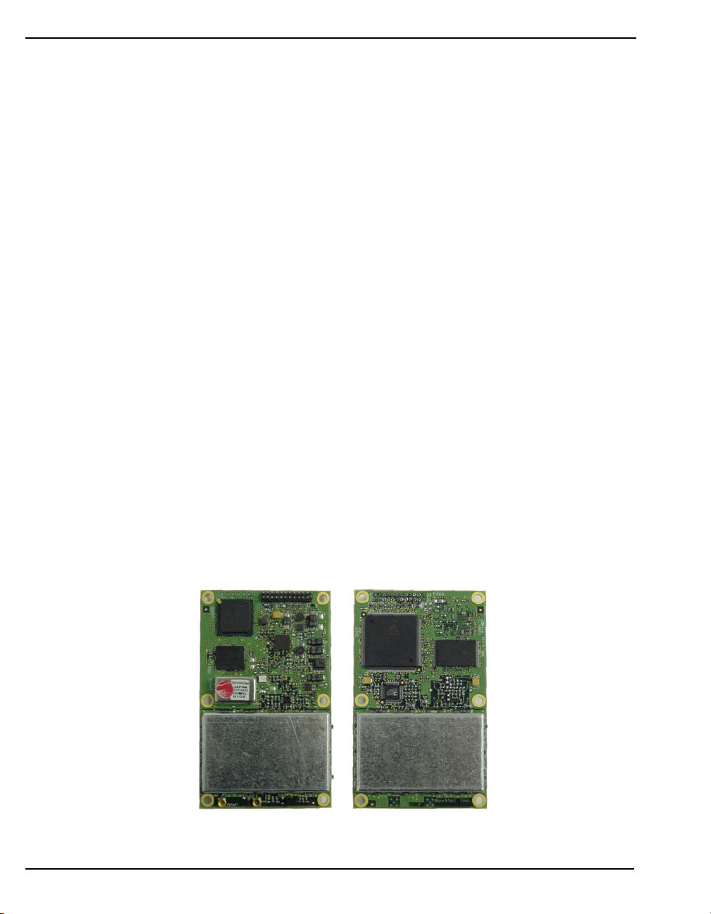
1.2.1 OEM4-G2L GPSCard
The OEM4-G2L provides the best features of the OEM4 family in a compact, low-power card. In
addition to the functionality given in Section 1.1.1 on Page 17, the OEM4-G2L offers:
• 40% smaller than the OEM4-G2
• 15% less power consumption compared to the OEM4-G2 and 35% less than th e original
OEM4
•Two serial ports
• USB support (with firmware version 2.100 or higher)
• An external oscillator input
• Two mark inputs for triggering the output of logs on external events
• Programmable PPS output (with firmware version 2.100 or higher)
• Auxiliary strobe signals for status and synchronization
• Full compatibility with other OEM4 family products
Included with the OEM4-G2L is a wrist-grounding strap to prevent ESD damage when handling the
card and a CD containing NovAtel’s GPS PC utilities and product documentation.
For technical specifications on the OEM4-G2L, please see Section A.2, starting on Page 110.
Figure 1: OEM4-G2L GPSCard
Top
18 OEM4 Family Installation and Operation User Manual Rev 12
Bottom
Introduction Chapter 1
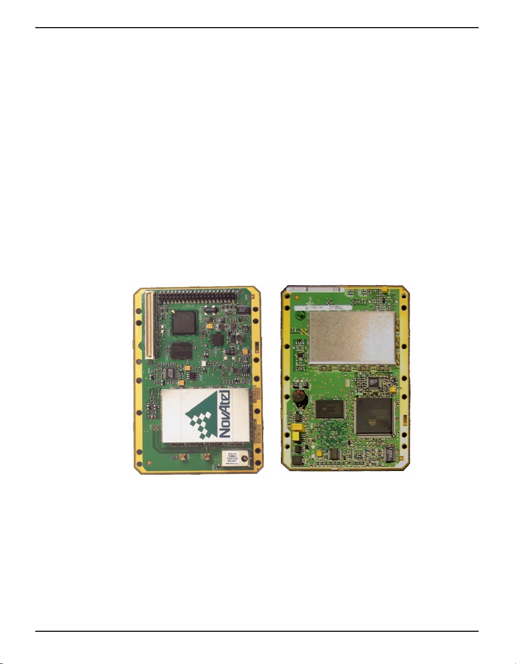
1.2.2 OEM4-G2 GPSCard
The OEM4-G2 is the second generation of the original OEM4. In addition to what is listed in Section
1.1.1 on Page 17, the OEM4-G2 offers:
• An improved processor and memory
• 20% less power consumption compared to the OEM4
• Three serial ports, one of which is user-selectable for RS-232 or RS-422
• USB support (with firmware version 2.100 or higher)
• An external oscillator input
• Two mark inputs for triggering the output of logs on external events
• Programmable PPS output (with firmware version 2.100 or higher)
• Auxiliary strobe signals for status and synchronization
• On-board power conversion, eliminating the need for external power conditioning
• Full compatibility with other OEM4 family products
Included with the OEM4-G2 is a wrist-grounding strap to prevent ESD damage when handling the
card and a CD containing NovAtel’s GPS PC utilities and product documentation.
For technical specifications on the OEM4-G2, please see Section A.3, star t ing on P age 115.
Figure 2: OEM4-G2 GPSCard
Top
OEM4 Family Installation and Operation User Manual Rev 12 19
Bottom

Chapter 1 Introduction
1.3 Enclosures
The OEM4 family GPSCards can be housed in a ProPak or FlexPa k enclos ure to pr ovide a compl ete
receiver solution. When connected to an antenna and a power source, the enclosure and associated
GPSCard together form a fully functioning GPS receiver.
The enclosures offer protection against environmental conditions and RF interference. In addition,
they provide an easy-to-use interface to the GPSCard’s data, power, and status signals. Th e enclosures
offer GPS integrators an effective, self-contained system for indoor applications while also providing
a rugged, water, shock, and vibration resistant housing for outdoor applications.
The table below provides a comparison between the features available on the various enclosures. The
sections that follow give details on each of them.
Table 1: Enclosure Features Comparison
Feature ProPak-G2
GPSCard
Supported
Serial Ports 3 ports on 3
USB Not available Not available Yes
Strobe Port DB-9S or
Input Voltage +7 to +18 V +7 to +15 V +8 to +16 V
OmniSTAR LBand Differential
Corrections
c
OEM4-G2 OEM4-G2 OEM4-G2L
DB-9P or 2
LEMO
connectors
a
LEMO
Not available Yes Not available
ProPak-LB FlexPak
3 Switchcraft 2 Deutsch
Switchcraft
b
Deutsch
a. For the ProPak-G2 with LEMO connectors, strobe
signals are available on the COM2 connector.
b. For the ProPak-LB, the strobes are available at the
COM1 connector, which also provides RS-232 signals for one of the serial ports.
c. A subscription to the OmniSTAR service is required.
20 OEM4 Family Installation and Operation User Manual Rev 12
Introduction Chapter 1
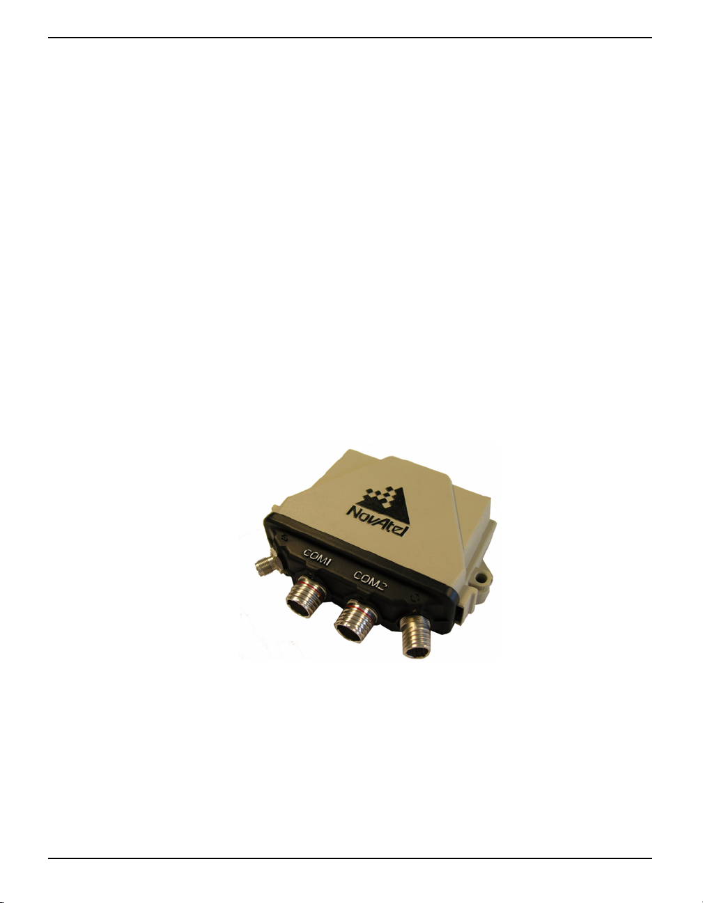
1.3.1 FlexPak
NovAtel's FlexPak is a rugged, waterproof housing for the OEM4-G2L positioning engine. As a
result, the FlexPak can deliver centimeter-level positioning in a compact, lightweight enclosure. It
provides dual-frequency positioning with a USB interface and an API option for supporting custom
applications.
The FlexPak offers the following features:
• A shock and dust resistant enclosure
• Waterproof to IEC 60529 standards IPX4 and IPX7
• Low power consumption
• Two RS-232 serial ports
• USB support
• PPS output
• Configurable mark inputs
• I ndicators for position, communication status and power
The following accessories are included with the FlexPak:
• 1 automotive power adapter cable
• 1 null-modem serial cable with DB-9 connector
• A CD containing NovAtel’s GPS PC utilities and product documentation
For technical specifications on the FlexPak, please see Section A.4, starting on Page 121.
Figure 3: FlexPak Enclosure
OEM4 Family Installation and Operation User Manual Rev 12 21

Chapter 1 Introduction
1.3.2 ProPak-G2
The ProPak-G2 provides a hardware interface between your equipment and the NovAtel OEM4-G2
GPSCard. It is a rugged, sealed enclosure that provides protection against adverse environments. It is
available in two versions, one with DB-9 connectors to access data and status signals and the other
with LEMO-brand connectors.
The ProPak-G2 offers the following features:
• A mounting enclosure with a PCB interconnect back plane
• Three serial ports provided on either three DB-9P connectors or two LEMO connectors
• Auxiliary status and synchronization signals
• GPS antenna and power ports
• I ndicators to provide power and communication status
The following accessories are included with the ProPak-G2:
• 1 automotive power adapter cable
• 2 or more data cables
• A CD containing NovAtel’s GPS PC utilities and product documentation
For technical specifications on the ProPak-G2, please see Section A.5, starting on Page 128.
Figure 4: ProPak-G2 Enclosure
Figure 5: ProPak-G2 Back End-Cap (DB-9 Version)
22 OEM4 Family Installation and Operation User Manual Rev 12

Introduction Chapter 1
1.3.3 ProPak-LB
The NovAtel ProPak-LB provides a hardware interface between your equipment and the NovAtel
OEM4-G2 GPSCard. Additionally, within the ProPak-LB, an OmniSTAR L-band receiver provides
correction data. As shown in Figure 6, the ProPak-LB is a rugged, sealed enclosure, suitable for
adverse conditions.
In order to receive OmniSTAR L-band corrections, a subscription to the OmniSTAR service is
required. See Section 4.5 on Page 48 or the ProPak-LB Quick Start Guide, provided with the
receiver, for details.
In addition to support for OmniSTAR positioning, the ProPak-LB provides the following:
• A rugged, environmentally-sealed enclosure
• 3 serial ports with Switchcraft-brand connectors
• GPS antenna and power ports
• Auxiliary strobe signals for status and synchronization
• Indicator to provide status information
The following accessories are included with the ProPak-LB:
• 1 automotive power adapter cable
• 3 straight serial port cables
• A CD containing NovAtel’s GPS PC utilities and product documentation
For technical specifications on the ProPak-LB, please see Section A.6, starting on Page 138.
Figure 6: ProPak-LB
Figure 7: ProPak-LB Back End Cap
OEM4 Family Installation and Operation User Manual Rev 12 23
Chapter 1 Introduction
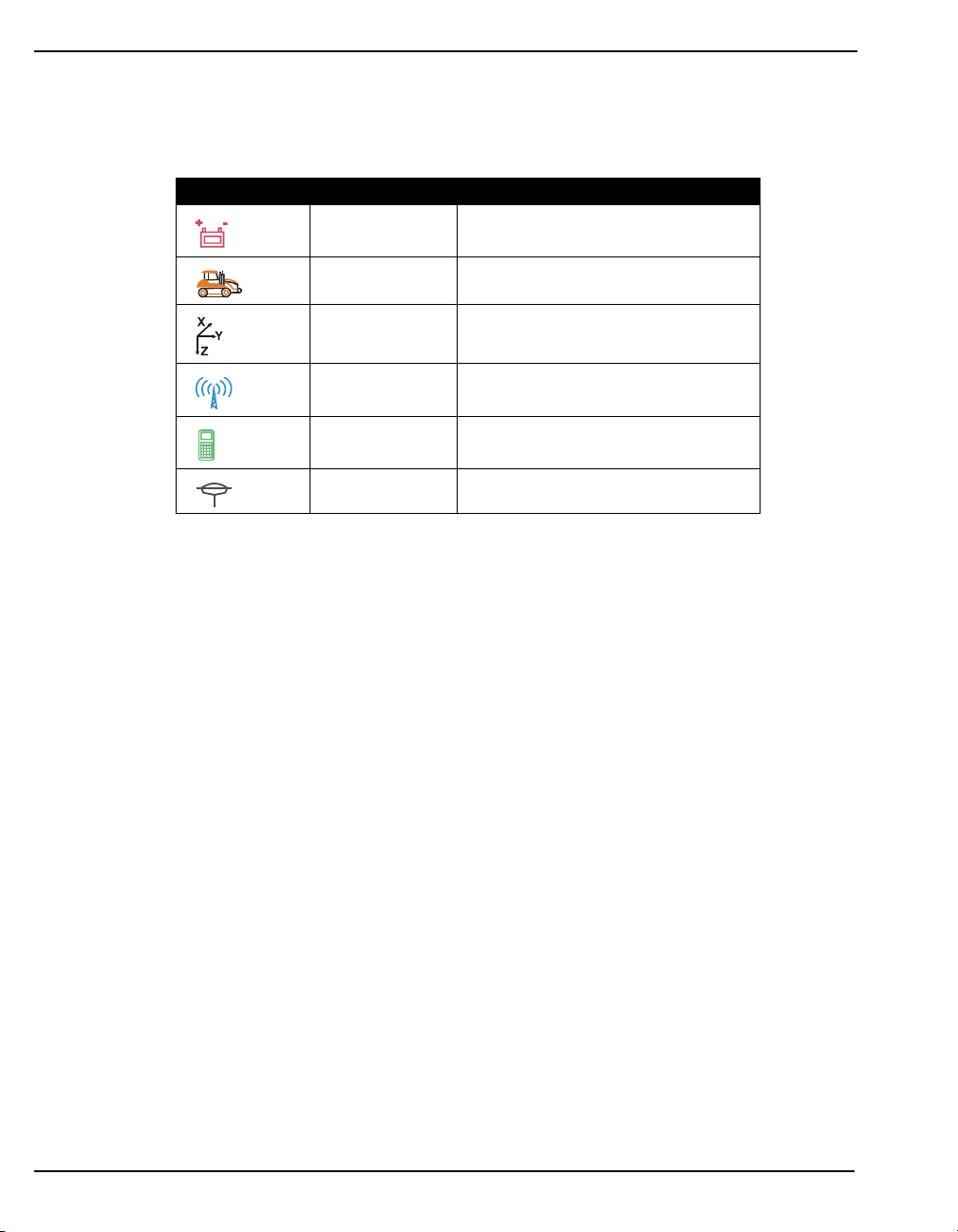
Figure 7 shows the s ix por ts on th e back end cap of the ProPak-LB that are labeled with icons. Table 2
provides information on these ports, including the name used to reference each of them throughout
this manual.
Table 2: ProPak-LB Interface
Icon Name Description
PWR DC power input
RES Reserved
COM1
COM2
COM3 RS232 and general I/O signals
ANT Antenna connection
RS232 signals and auxiliary strobe
signals
RS232 signals with optional flow
control
24 OEM4 Family Installation and Operation User Manual Rev 12
Chapter 2 Receiver System Overview
In addition to a NovAtel OEM4 family GPSCard, a complete GPS receiver system typically contains
four other major components:
• A FlexPak or ProPak enclosure or a custom enclosure and wiring harness
• A GPS antenna (and optional LNA power supply)
• A power suppl y
• Data communications equipment
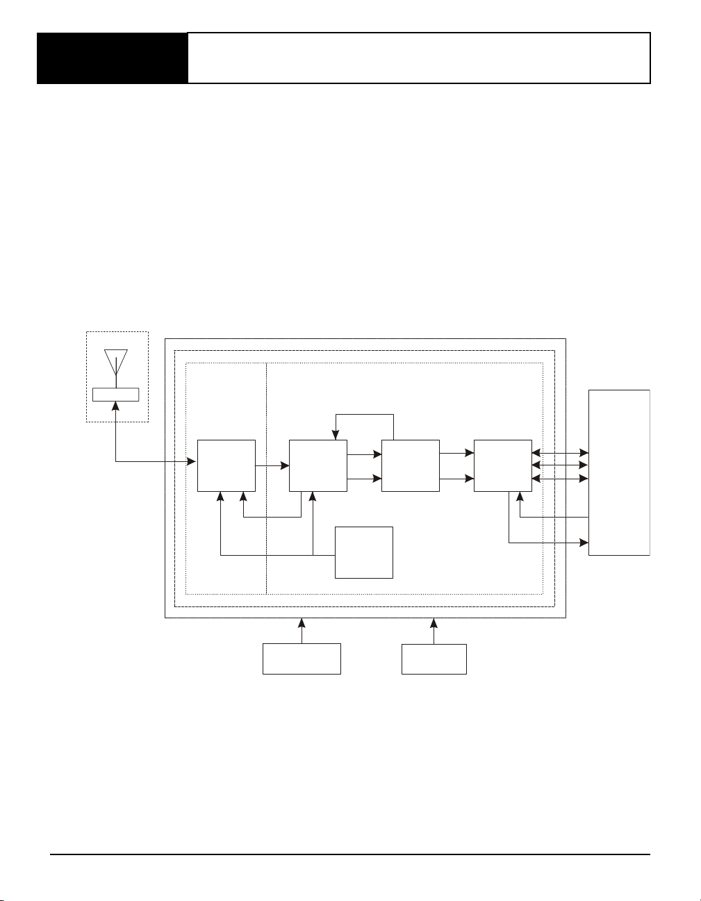
The overall system is represented in Figure 8. A brief description of each section follows the figure.
Details of installation and set up are provided in Chapt er 3, Installation and Set Up on Page 28.
Figure 8: GPS Receiver System Functional Diagram
GPS antenna
L N A
Enclosure
GPSCard
RF Section Digital Section
Controls
R F - I F
Sections
A G C
Clock
Optional
LNA power)
Signal
Processor
Clock
VCTCXO
32-bit
C P U
Powe r
supply
System
I / O
Data & signal
processing
equipm ent
COM 1
COM 2
COM 3
Input
timing signal
Output
timing signal
2.1 GPSCard
NovAtel’s GPSCards c onsist of a ra dio frequency (RF) and a digital electronics section.
OEM4 Family Installation and Operation User Manual Rev 12 25

Chapter 2 Receiver System Overview
2.1.1 Radio Frequency (RF) Section
The receiver obtains a partially filtered and amplified GPS signal from the antenna via the coaxial
cable. The RF section performs the translation from the incoming RF signal to an IF signal usable by
the digital section. It also supplies power to the active antenna’s LNA through the coaxial cable while
maintaining isolation between the DC and RF paths. The RF section can reject a high level of
potential interference (e.g., MSAT, Inmarsat, cellular phone, and TV sub-harmonic signals).
2.1.2 Dig ital Electronics Section
The digital section of the receiver , receiv es a down -converted, amp lified GPS signal which it dig itizes
and processes to obtain a GPS solution (position, velocity and time). The digital section consists of an
analog-to-digital converter, a 3 2-bit system processor , memory, control and configuration logic, signal
processing circuitry, serial peripheral devices, and supporting circuitry.
The digital section performs the translations and calculations necessary to convert the IF analog
signals into usable position and status information. It also hand les all I /O f unctions, including the
auxiliary strobe signals, which are described in detai l in Sec tion 3.3.1 on Page 36. For input and
output levels please see Appendix A, Input/Output Strobes on Page 113 for the OEM4-G2L and Page
118 for th e OEM4-G2.
2.2 Enclosure and Wiring Harness
As discussed in Section 1.3 on Page 20, an enclosure is necessary to protect the GPSCard from
environmental exposure and RF interference. If a FlexPak or ProPak is not being used as the
enclosure, a wiring harness will also be required to provide an interface to the GPSCard’s antenna and
power inputs and data and status signals.
2.3 GPS Antenna
The purpose of the GPS antenna is to convert the electromagnetic waves transmitted by the GPS
satellites into RF signals. An active GPS antenna is required for the receiver to function properly.
NovAtel’s active antennas are recommended.
2.3.1 Optional LNA Power Supply
Power for the antenna LNA is normally supplied by the receiver. However, if a different type of
antenna is required that is incompatible with this supply, then you could connect an external power
source to the receiver.
External LNA power is not possible with a FlexPak or ProPak receiver.
26 OEM4 Family Installation and Operation User Manual Rev 12

Receiver System Overview Chapter 2
2.4 Principal Power Supply
A single external power supply capable of delivering 5 W is necessary to operate the receiver. See
Appendix A, Technical Specificatio ns starting on Page 109 for details.
WARNING: If the voltage supplied is below the minimum specification, the receiver will
suspend operation. If the voltage supplied is above the maximum
specification, the receiver may be permanently damaged, voiding your
warranty.
2.5 Data Communications Equipment
A PC or other data communications equipment is necessary to communicate with the receiver and, if
desired, to store data generated by the receiver.
OEM4 Family Installation and Operation User Manual Rev 12 27

Chapter 3 Installation and Set Up
This chapter contains instructions and tips to set up your NovAtel receiver to create a GPS receiver
system similar to that described in C hapter 2, Receiver System Overview on Page 25.
3.1 Additional Equipment Required
In order for the receiver to perform optimally, the following additional equipment is required:
• I f your receiver has been purchased as a GPSCard without an enclosure, an interface for
power, communications, and other signals and an enclosure to protect against the
environment
• A NovAtel GPS antenna
• A quality coaxial cable (and interconnect adapter cable as necessary)
• Data communications equipment capable of serial communications
• A serial cable (if not included with the receiver)
• A power suppl y
• A power cable (if not included with the receiver)
CAUTION: When the OEM4 family receiver is installed in a permanent location, such
as in a building, it should b e protected by a lightening protection device
according to local building codes. See also Warranty Policy on Page 12.
3.1.1 Selecting a GPS Antenna
An active antenna is required because its low-noise ampl ifier (LN A) boosts the power of the incoming
signal to compensate for the line loss between the antenna and the receiver.
NovAtel offers a variety of single an d dual-frequency GPS antenna models, as indicated in the table
below. All include band-pass filtering and an LNA. The GPS antenna you choose will depend on your
particular application. Each of these models offer exceptional phase-center stability as well as a
significant measure of immunity against multipath interference. Each one has an environmentallysealed radome.
Table 3: NovAtel GPS Antenna Models
Models Frequencies Supported
701, 501, 511, 521, 531 L1 only
702, 502, 503, 512 L1 and L2
600-LB L1 and L2 plus L-band
OEM4 Family Installation and Operation User Manual Rev 12 28

Installation and Set Up Chapter 3
3.1.2 Choosing a Coaxial Cable
An appropriate coaxial cable is one that is matched to the impedance of the antenna a nd receiver being
used (50 ohms), and whose line loss does not exceed 10.0 dB. If the limit is exceeded, excessive
signal degradation will occur and the receiver may not be ab le to meet its per form ance specifications.
NovAtel offers a variety of coaxial cables to meet your GPS antenna interconnection requirements,
including:
• 5, 15, or 30 m antenna cables with TNC male connectors on both ends (NovAtel part
numbers C006, C016 and C 032 respectively)
• 22 cm interconnect adapter cable with MMCX male and TNC female connectors (NovAtel
part number GPS-C002)
Note that a conversion is required between the female MMCX connector on the OEM4-G2L and
OEM4-G2 GPSCards, and the female TNC connector on Novatel’s GPS antennas.
Your local NovAtel dealer can advise you about your specific configuration. Should your application
require the use of cable longer than 30 m you will find the application note RF Equipment Selection
and Installation at our website, www .nov at el.com
Service directly.
High-quality coaxial cables should be used because a mismatch in imped ance, possible with lower
quality cable, produces reflections in the cable that increase signal loss. Though it is possible to use
other high-quality antenna cables, the performance specifications of the OEM4 family receivers are
warranted only when used with NovAtel-supplied accessories.
, or you may obtain it from NovAtel Customer
3.1.3 Power Supply Requirements
This section contains information on the requirements for the input power to the receiver. See
Appendix A, Technical Specificatio ns starting on Page 109 for more powe r supply specifications.
WARNING: If the voltage supplied is below the minimum specification, the receiver will
suspend operation. If the voltage supplied is above the maximum
specification, the receiver may be permanently damaged, voiding your
warranty.
3.1.3.1 GPSCards
The OEM4-G2 GPSCard contains a DC to DC converter that is very tolerant to noise and ripple at its
input. A tightly regulated input supply to the card is not required, as long as it falls within the given
input range. A tightly regulated input supply to the OEM4-G2L GPSCard is required. The power
supply used for any GPSCard should be capable of 5 W. The voltage input range for each GPSCard
type is given in the table below.
Table 4: Voltage Input Ranges for GPSCards
GPSCard Power Input Range
OEM4-G2L +3.3 ± 0.15 VDC
OEM4-G2 +4.5 to +18 VDC
OEM4 Family Installation and Operation User Manual Rev 12 29

Chapter 3 Installation and Set Up
All members of the OEM4 family receivers are designed to prevent internal damage when subjected
to a reverse polarity power connection. The OEM4-G2 also provides protection from short over
voltage events. It is recommended that appropriate fuses or current limiting be incorporated as a safety
precaution on all power lines used. Use a sufficient gauge of wire to ensure that the voltage at the
connector is within the GPSCard’s requirements.
3.1.3.2 FlexPak and ProPak Enclosures
The FlexPak and ProPak enclosures are supplied with an automobile power adapter with a built-in
slow-blow fuse for use with a standard 12 VDC automobile power outlet. NovAtel’s Aircraft Power
Conditioner can also be used to provide further protection for your receiver.
If a different supply is desired, the table below provides the input range required as well as the type of
connector required to mate with the receiver’s power connector . The supply should be capable of 5 W.
Table 5: Power Requirements for Enclosures
Enclosure Power Cable Connector Required Power Input Range
FlexPak
ProPak-G2
ProPak-LB
3-pin Deutsch socket connector
4-pin LEMO socket connector
2-pin Switchcraft socket connectora labelled
a
labelled
a
labelled PWR
+8 to +16 VDC
+7 to +18 VDC
+7 to +15 VDC
a. See Appendix J, Replacement Parts starting on Page 181 for part numbers for the
connectors.
3.2 Installation Overview
Once you have selected the appropriate equipment, complete the following steps to set up and begin
using your NovAtel GPS receiver.
1. If your receiver has been provided as a GPSCard without an enclosure, install the card in an
enclosure with a wiring harness, as described in Section 3.2.1 on Page 32.
2. Mount the GPS antenna to a secure, stable structure, as described in Section 3.2.2 on Page 34.
3. Connect the GPS antenna to the receiver using an antenna RF cable, using the information given
in Section 3.2.3 on Page 34.
4. Apply power to the receiver, as described in Section 3.2.4 on Page 35.
5. Connect the receiver to a PC or other data communications equipment by following the
information given in Section 3.2.5 on Page 35.
Figure 9 on the next page shows a typical set up for an enclosed receiver.
30 OEM4 Family Installation and Operation User Manual Rev 12
 Loading...