

Novatel MT 4100, MT4100X-UG001 User Manual
MT4100X-UG001
MT 4100
Version
1.3 April 9, 2015
User Guide

NOVATEL WIRELESS COPYRIGHT STATEMENT
©2015 Novatel Wireless, Inc. All rights reserved. The information contained in this document is subject
to change without notice and should not be construed as a commitment by Novatel Wireless, Inc.
NOVATEL WIRELESS TRADEMARKS AND SERVICE MARKS
Novatel Wireless is a trademark of Novatel Wireless, Inc., and the other trademarks, logos, and service
marks (collectively the “Trademarks”) used in this user manual are the property of Novatel Wireless or
their respective owners. Nothing contained in this user manual should be construed as granting by
implication, estoppel, or otherwise, a license or right of use of Novatel Wireless or any other Trademark
displayed in this user manual without the written permission of Novatel Wireless or its respective
owners.
Novatel Wireless, and the Novatel Wireless logo are all trademarks of Novatel Wireless, Inc.
MiFi® and the MiFi logo are registered trademarks of Novatel Wireless, Inc.

Contents
Introduction 1
Description 2
Technical Specifications 3
Features and Functions 6
GPS 7
Power 8
LEDs 9
22-Pin I/O Connector 10
Battery Disconnect Switch 11
Low-Power Sleep Mode 12
Accelerometer 13
1-Wire® Interface 14
Device Check-In 15
Garmin Fleet Management Interface (GFMI) 16
Installation 17
SIM Installation 18
Device Installation 21
Precautions and Guidelines 21
Mounting Locations 22
Mounting Methods 23
Device Orientation 24
Mounting and Installing the Device 25
Network Test Procedure 26
Test Preparation 27
Verifying Communications with the Computer 28
Configuring the Modem to Access the GPRS Network 29
Checking the Device Connection to the Cellular Network 30
Configuring the Modem to Talk to the Test Server 31
Verifying Server Connectivity 32
Accessories 34
Metal Lever 35
Mounting Bracket 36
Cables 37
Power Cable 38
Integration and Development Cable 39
iii

Cable Wiring Guides 40
22-Pin I/O Connector Parameters 41
Compliance and Regulatory 43
General Disclaimer 44
Warranty Information 45
Regulatory Compliance 48
Battery Information and Safety Requirements 50
iv

1
Introduction
Description
Technical Specifications
1
Description
Novatel Wireless' MT 4100 keeps you connected to your assets. It is more than just a communication
device, it is a full-featured telematics solution designed to optimize your mobile resources and improve
your company's bottom line. MT 4100 offers two serialinterfaces, 1-wire driver ID support, multiple
GPIO, polygon geo-fencing, driver behavior reporting, and an optional backup battery. MT 4100
includes optional routing and optimization with Garmin® Fleet Management Interface (FMI)—a key part
of today’s most useful, versatile, and cost-efficient fleet management solutions.
When you add N4A™ Communications and Management platform to your MT 4100 (shown here), you
can provision, monitor, and reconfigure the MT 4100 remotely from almost anywhere in the world.
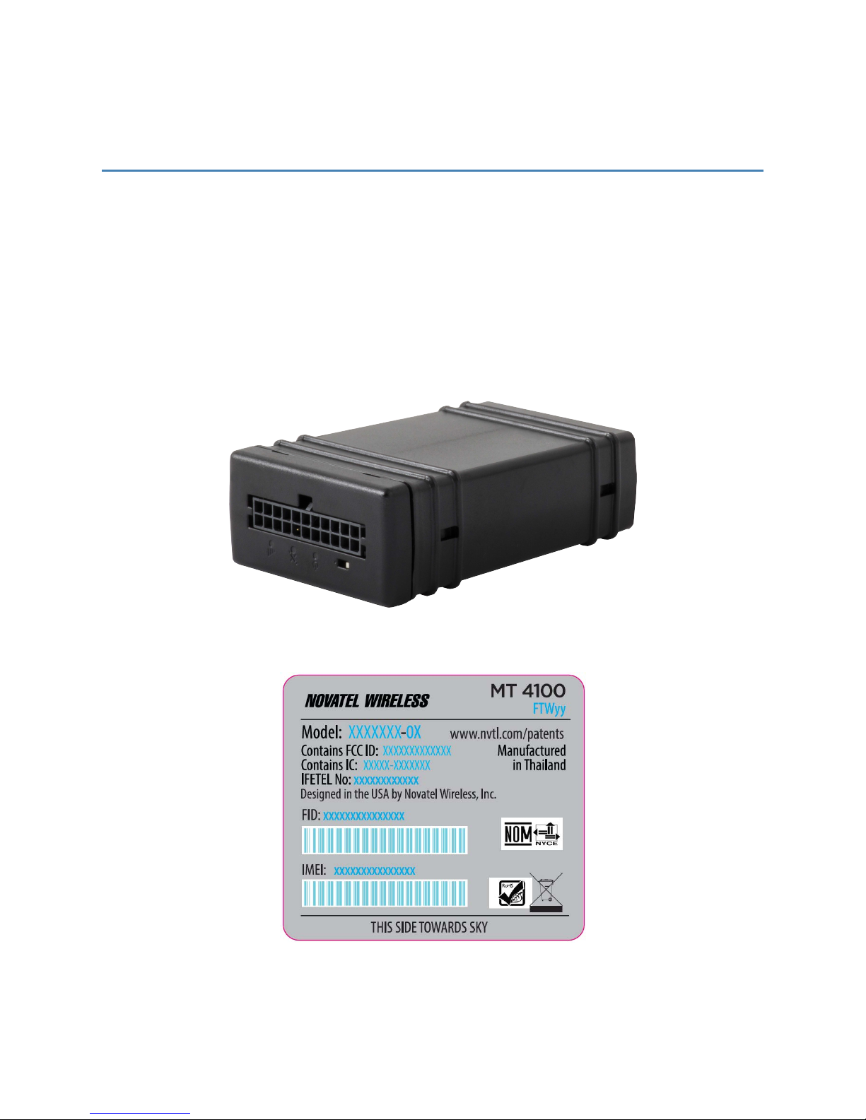
The MT 4100 has a printed label on the top side of the device. The following figure shows a sample label
with the type of information it includes.
Figure 1-1: MT 4100 Label
MT 4100 User Guide 2

Technical Specifications
General
Name: MT 4100
Models: RTT2201, UMT2202, UMT2203
Approvals: FCC, CE, RoHS, Industry Canada
Housing: Rugged textured plastic enclosure UL94-Vo fire
Weight: Without Battery: 71.8 grams
With Battery: 81 grams
Dimensions: 82 x 52 x 26.4 mm
Battery: Rechargeable lithium-ion battery (230 mAh)
Recharge Temperature Range 0 to +45º C
Operating Voltage: 9 - 32 VDC operational for 12 V & 24 V systems
Radio Technology
Downlink/Uplink
- CDMA: 153 Kbps
- GPRS: 80 Kbps, 40 Kbps
- EDGE: 237 Kbps,118 Kbps
- WCDMA Release 99: 384 Kbps, 384 Kbps
- HSDPA Release 5: 3.6 Mbps, 3.6 Mbps
Cellular Technology: 1xRTT (CDMA2000) or HSDPA (UMTS 3G)
1xRTT (CDMA): 850/1900
HSDPA (UMTS):
850/1900 (Bands V, II) (NA) or
900/2100 (Bands VIII, I) (ROW)
GSM/GPRS/EDGE Fallback:
850/1900 Mhz Fallback (NA)
900/1800 Mhz Fallback (ROW)
Packet Data
Packet Data IS-95, IS-2000
SMS Functionality
- HSDPA SMS: Text, PDU, MO/MT, Cell Broadcast
- CDMA SMS: Text, MO/MT
MT 4100 User Guide 3
Environmental
Operating Temperature: Battery version: -20º C to 60º C
Non battery version: -30º C to 85º C
Storage Temperature: -40º C to 85º C
Humidity:
Vibration Stability: In accordance with SAE J1211
Battery version: Up to 89% non-condensing
Non-battery version: Up to 95% non-condensing
Components
GPS Protocols: NMEA, Binary
Buffered GPS Message Feature: Yes
Accelerometer: 3-axis digital
SIM Access: Internal (HSDPA models only)
Cellular Antenna: Internal
GPS Antenna: Internal
Serial Data I/O: (2) RS-232 (RX, TX, CTS, RTS) (RX, TX on 2nd)
I/O Connector: 22-pin Molex
(3) digital outputs
(2) analog inputs (0-16 V, 0-32 V)
(5) digital inputs
1-wire interface (Driver ID)
Ignition Sense
Garmin® FMI: Optional, Version 2.6 with integrated safe mode and speed limit alerts
LEDs: Power (green), Cellular (green), GPS (red)
Analog To Digital Converter (ADC1): 10 bit, 0-16 V input range, +/- 1%, 40 V max, scaling 0.0156 per bit
(16 VDC/1023)
Analog To Digital Converter (ADC2): ADC2: 10 bit, 0-32 V input range, +/- 1%, 40 V max scaling 0.0312 per
bit (32 VDC/1023)
Protocols
Host Protocols: AT commands, UDP API, FOTA
Internal Protocols: UDP API, TCP API
API Control/Status: AT commands, UDP API, TCP API, AT commands over SMS
MT 4100 User Guide 4

Part Numbers
RTT2201-00 CDMA 1xRTT w/ Backup Battery
RTT2201-01 CDMA 1xRTT w/o Backup Battery
UMT2202-00 ROW (HSDPA Version with Battery)
UMT2202-01 ROW (HSDPA Version without Battery)
UMT2203-00 NA (HSDPA Version with Battery)
UMT2203-01 NA (HSDPA Version without Battery)
BRK4100 Mounting bracket
CAB2448-01 Power, ground, ignition cable
CAB2200-02 Power and full I/O integration/development cable
Document References
MT4100R-AT144 MT 4100 R AT Command Reference
MT4100U-AT144
ENF0000AN003 Accelerometer Guide Application Note
ENF0000AN009 Low Power Sleep Mode Application Note
ENF0000AN002 FOTA Application Note
ENF0000CB001 API Reference
ENF0000XG001 GFMI Technical Guide
ENF0000AN014 Access the Novatel Wireless Test Server Application Note
ENF0000AN010 MT Decoding NMEA Messages Application Note
ENF0000AN018 1-Wire Interface Application Note
MT 4100 UAT Command Reference
Certifications
FCC: Yes
CE: Yes
RoHS Compliant: Yes
Industry Canada: Yes
Additional Features
FOTA (Firmware Over-the-Air) I/O control
Binary reporting
Timed reporting
MT 4100 User Guide 5

2
Features and Functions
GPS
Power
LEDs
22-Pin I/O Connector
Battery Disconnect Switch
Low-Power Sleep Mode
Accelerometer
1-Wire® Interface
Device Check-In
Garmin Fleet Management Interface (GFMI)
6

GPS
GPS functions include:
l
NMEA protocol (to update all data points)
l
Novatel Wireless Binary Packets
l
Buffered GPS message feature
l
Geo-fencing (helps secure devices within a defined location)
l
Virtual odometer (uses GPStechnology to track devices)
GPS Measurements
Dimension Measurement
Time to first fix - Cold Start @ -130 dBm with 20 m accuracy < 60 sec
Time to first fix - Hot Start @-130 dBm with 20 m accuracy ≤ 3 sec
Time to first fix - Reacquisition @-130 dBm with 20 m accuracy < 3 sec
Acquisition Sensitivity with 50 m accuracy < -140 dBm
Tracking sensitivity with < 50 m accuracy < -157 dBm
Tracking sensitivity with > 50 m accuracy -162 dBm
Accuracy, R 95%, Clear view of the sky, 24 hours < 15 meters
For more information on NMEA and Binary Packets, see Novatel Wireless document MT Decoding NMEA
Messages Application Note (ENF0000AN010).
For more information on Virtual Odometer, see Novatel Wireless document APIReference
(ENF0000AN010).
MT 4100 User Guide 7

Power
The MT 4100 accepts 9-32 VDC, minimum 2 amps input power. This allows the device to be used on
both 12 V and 24 V vehicles per SAE specifications, including protection for jump-starting 24 V vehicles.
Pins 17 and 18 on the 22-Pin IO connector are the power input and pins 6 and 7 are ground.
All power and ground pins must be connected.
Power Consumption
Mode Current GPS
CDMA BC0 - 800 MHz < 66 mA @ 14.2 V GPS off; lowest current consumption while still
being able to contact the device
CDMA BC1 - 1900 MHz < 63 mA @ 14.2 V GPS on
Idle (GPS on) < 54 mA @14.2 V Registered
Idle (GPS off) < 33 mA @14.2 V Registered
Low Power Sleep Mode <1.3 mA @14.2 V GPS off
Bench Testing / Programming
WARNING! After performing a firmware upgrade the device will respond that the firmware load is
complete. However, power must remain applied to the device for approximately two minutes after the
firmware upgrade completion message is received. This allows time for the upgrade to be applied to
the auxiliary processor. The user can confirm it is safe to remove power by sending the AT$OBDVER?
command. If the upgrade is still processing, the device will respond with an error. If the upgrade is
complete, the device willrespond with the current software version.
MT 4100 User Guide 8
LEDs
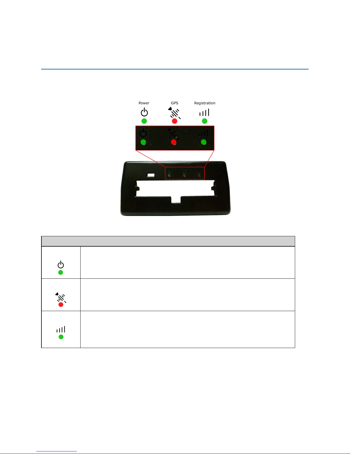
The MT 4100 includes LEDs to indicate Power, GPS, and Registration status. The following image shows
the location of each LED.
The LEDs are described in the following table.
MT 4100 LEDs
PWR:
GPS:
Registration:
This LED indicates power to the GPS module. LED is on ~1 second after powered on and
the GPS module is operational. This LED is off when powered off or when the MT 4100
enters Low-Power Sleep mode. Note: If you disable the GPS module, you must apply
power for this LED to turn on.
You can configure this LED to display registration, GPS fix status, or other user functions.
By default, this LED indicates GPS fix status. The LED remains off when it receives invalid
GPS data. The LED remains on when it receives valid GPS data.
You can configure this LED to display registration or other user functions. By default, this
LED indicates network registration status. If this LED stays off, this indicates that the device
is not attempting to register to the network. If the LED blinks, it indicates that the device is
trying to connect to the network. If the LED is always on, this indicates that the device has
connected to the network.
MT 4100 User Guide 9
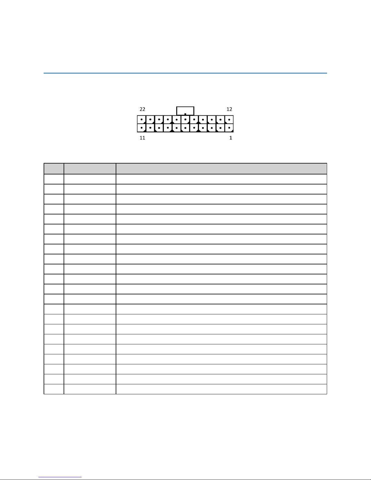
22-Pin I/O Connector
The MT4100 has a 22-pin I/O connector. The following image shows the pin layout.
The 22-Pin I/O Connector provides the following functionality:
Pin # User Name Description
1 Digital Input #5 Digital Input #5 (GPI12)
2 Digital Input #4 Digital Input #4 (GPI11)
3 1-Wire 1-Wire® Interface / Note: Maximum voltage on this pin is 3.3 VDC
4 ADC In #2 Analog-to-Digital Input, 0 – 32 VDC
5 ADC In #1 Analog-to-Digital Input, 0 – 16 VDC
6 Ground System Ground
7 Ground System Ground; Connector has longer pin for MFBL
8 Digital Input #2 Digital Input #2 (GPI9)
9 Digital Input #1 Digital Input #1 (GPI1)
10 RS-232 CTS1 RS-232 CTS1 Out / Note: Output only. Input voltages should not be applied.
11 Ignition Sense Vehicle Ignition Sense
12 RS-232 TX2 RS-232 TX2 In / Note: -25 VDC to 25 VDC
13 RS-232 RX2 RS-232 RX Out / Note: Output only. Input voltages should not be applied.
14 Digital Output 1 Output, High-Current Sink, Low-Current Source, Latched (GPO2)
15 Digital Output 2 Output, High-Current Sink, Low-Current Source, Latched (GPO5)
16 Digital Output 3 Output, High-Current Sink, Latched (GPO3)
17 Power In Vehicle Power from 12 or 24 V Vehicles
18 Power In Vehicle Power from 12 or 24 V Vehicles
19 Digital Input #3 Digital Input #3 (GPI10)
20 RS-232 RTS1 RS-232 RTS1 In / Note: -25 VDC to 25 VDC
21 RS-232 TX1 RS-232 TX1 In / Note: -25 VDC to 25 VDC
22 RS-232 RX1 RS-232 RX1 Out / Note: Output only. Input voltages should not be applied.
MT 4100 User Guide 10
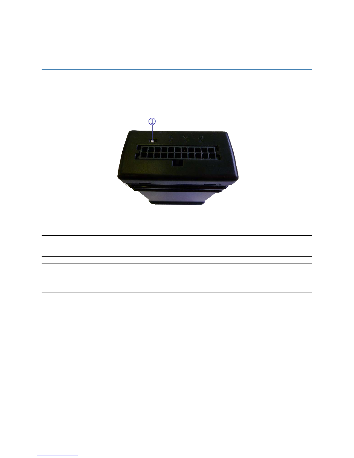
Battery Disconnect Switch
Use the MT 4100 Battery Disconnection Switch to remove battery power from the device (battery
models only). Move the switch toward the dot to place the battery in the ON position. Move the switch
away from the dot to place the battery in the OFF position. The following figure shows the MT 4100
Battery Disconnection Switch in the OFF position.
You must place the Battery Disconnection Switch in the ON position before using the optional backup
battery for programming or operating the MT 4100.
WARNING! If the Battery Disconnection Switch remains in the ON position with no external power
applied for an extended period of time, then the battery may significantly lose its charging capability.
WARNING! Before connecting to any auxiliary I/O device, you must apply power to the MT 4100 by
moving the Battery Power Switch to the ON position. Failure to apply power to the MT 4100 before
connecting auxiliary devices may result in damage to the attached I/O device.
NOTE: Move the Battery Disconnection Switch to the OFF position when transporting the device by
air.
MT 4100 User Guide 11

Low-Power Sleep Mode
In Low-Power Sleep Mode (LPS), allmodem/GPS activity stops; this allows extreme power savings. The
auxiliary processor efficiently monitors system inputs based on the configuration assigned and willexit
LPS mode when needed. The current draw during LPS is:
< 1.5 mA @ 12 V
You can configure the MT 4100 to exit Low-Power Sleep Mode when:
l
Ignition detected
l
Motion detected
l
Input triggered
l
Elapsed-time expired
For more details, see Novatel Wireless document Power Saving Techniques Application Note
(ENF0000AN015).
MT 4100 User Guide 12

Accelerometer
The MT 4100 has two, three-axis digital accelerometers that provide the following features:
l
Motion alert (towing alert)
l
Driver behavior reporting
o
Rapid acceleration
o
Harsh braking
l
Configurable thresholds
o
Range settings
o
Mode (Normal, Sleep, Wakeup)
o
Wakeup pause (20 to 2560 msec)
o
Sample Rate (0 to 25 per second)
o
Filter Coefficient and Filter Bandwidth
o
Device Orientation Setup
For more information, please refer to Novatel Wireless document Accelerometer Guide Application Note
(ENF0000AN003).
MT 4100 User Guide 13
 Loading...