

Novatel MiLLennium OM-20000040 User Manual
OM-20000040 REV 1
OM-20000040 Rev 1
MiLLennium-GLONASS GPSCard
User Manual
User Manual
NovAtel Inc.

OM-20000040 rev 1
MiLLennium-GLONASS GPSCard
User Manual
Publication Number: OM-20000040
Revision Level: 1 99/11/18
Firmware Version: 6.48
PROPRIETARY NOTICE
Information in this document is subject to change without notice and does not represent a commitment on the part
of NovAtel Inc. The soft ware desc ribed in this docum ent is f urni shed under a license agreement or n on-dis closu re
agreement. The software may be used or copied only in accordance with the terms of the agreement. It is against
the law to copy the software on any medium except as specifically allowed in the license or non-disclosure
agreement.
No part of this manual may be reprod uced or transm itted in an y form or by any means , electronic o r mechan ical,
including photocopyin g and recordin g, for any purp ose without the express writ ten permiss ion of a duly authorized
representative of NovAtel Inc.
The information contained within this manual is believed to be true and correct at the time of publication.
NovAtel, ProPak, PowerPak, MiLLennium, GPSolution and Narrow Correlator are registered trademarks of
NovAtel Inc.
GPSCard, GPSAntenna RT-20 and RT-10 are trademarks of NovAtel Inc.
All other brand or product names are either trademarks or registered trademarks of their respective holders.
© Copyright 1999 NovAtel Inc. All rights reserved
Unpublished rights reserved under Int ernat ion a l copyri gh t l aws.
Printed in Canada on recycled paper. Recyclable.
2 GPS/GLONASS Receiver User Manual Rev 1

Table of Contents
T ABLE OF CONTENTS
TABLE OF CONTENTS
Warranty Policy 6
Customer Service and Caution Notice 7
Caution...................................................................................................................................... 7
Foreword 8
Congratulations ........................................................................................................................8
Scope ......................................................................................................................................... 8
Prerequisites .............................................................................................................................8
1 Introduction 9
1.1 MiLLennium-GLONASS GPSCard ..................................................................................9
1.2 GPS and GLONASS Overview .........................................................................................10
1.3 GPS System Design ...........................................................................................................10
1.3.1 The Space Segment .............................................................................................................10
1.3.2 The Control Segment ..........................................................................................................11
1.3.3 The User Segment ...............................................................................................................11
1.4 GLONASS System Design ................................................................................................11
1.4.1 The Space Segment .............................................................................................................11
1.4.2 The Control Segment ..........................................................................................................12
1.4.3 The User Segment ...............................................................................................................13
1.5 Time ...................................................................................................................................13
1.5.1 GPS Time vs. Local Receiver Time ...................................................................................13
1.5.2 GLONASS Time vs. Local Receiver Time ........................................................................13
1.6 Datum .................................................................................................................................13
2 Quick Start 15
2.1 Quick Start Steps ................................................................................................................15
3 Installation 17
3.1 System Configuration .........................................................................................................17
3.2 Minimum Configuration ....................................................................................................18
3.3 Anti-Static Precautions .......................................................................................................18
3.4 Installation Procedure .........................................................................................................18
3.4.1 Mounting The Printed Circuit Board ..................................................................................19
3.4.2 Preparing the Data, Signal & Power Harness .....................................................................19
3.4.3 External Power ....................................................................................................................21
3.4.4 RS232C Communications ..................................................................................................22
3.4.5 Strobe Signals .....................................................................................................................22
3.4.6 L1 GPS/GLONASS Antenna Considerations ....................................................................23
4 Operation 24
4.1 Before Operation ................................................................................................................24
4.2 Communications With The MiLLennium-GLONASS GPSCard ......................................24
4.2.1 Serial Port Default Settings ................................................................................................25
4.2.2 Communicating Using a Remote Terminal ........................................................................25
4.2.3 Communicating Using a Personal Computer .....................................................................25
4.3 Getting Started ...................................................................................................................25
4.3.1 Power-On ............................................................................................................................26
4.3.2 DOS ....................................................................................................................................27
4.3.3 Microsoft Windows 3.1 or Higher ......................................................................................28
4.4 Commands Common To All GPSCards ............................................................................28
4.4.1 Commands Specific to MiLLennium-GLONASS GPSCard .............................................28
4.5 Special Data Input Commands............................................................................................30
4.5.1 Almanac Data .....................................................................................................................30
GPS/GLONASS Receiver User Manual Rev 1 3

Table of Contents
4.5.2 Differential Corrections Data ............................................................................ ..................33
4.5.3 Calibration Data ............................... ... .... .......................... ..................................................33
4.6 Logs Common To All GPSCards .......................................................................................34
4.6.1 Logs Specific To MiLLennium-GLONASS GPSCard .......................................................34
4.6.2 Output Logging ..................... .... ............................................... ...........................................34
4.6.3 NovAtel Format Data Logs .................................................................................................36
4.6.4 NMEA Format Data Logs ...................................................................................................38
4.7 Differential Position Operation ..........................................................................................39
4.7.1 Pseudorange (PSR) Differential Positioning .......................................................................40
4.7.2 Real-Time Kinematic (RTK) Differential Positioning .......................................................41
4.7.3 Monitoring Your RTK Output Data ........................................................... .........................42
4.7.4 GPS-Only Operation with Standard MiLLennium-GLONASS GPSCard .........................42
4.8 Integrity Algorithm ..................................................... ..... ..................................................43
5 Firmware Updates and upgrades 44
5.1 Update/Upgrade Overview .................................................................................................44
5.1.1 Upgrading Using the $AUTH Command ........................................... ......................... .......44
5.1.2 Updating Using the LOADER Utility .................................................................................45
APPENDICES
A Anti-Static Practices 47
B Technical Specifications 49
C Common Unit Conversions 54
D Functional Overview 56
E ProPak II Enclosure 59
F PowerPak II Enclosure 73
G GLONASS Commands 82
G.1 GLONASS-Specific Commands .......................................................................................82
G.2 Other Relevant GPScard Commands................................................................................. 84
G.3 UnImplemented Commands...............................................................................................87
H NovAtel Format Logs 88
H.1 GLONASS-Specific Logs .................................................................................................88
H.2 Other Relevant GPSCard Logs .........................................................................................95
I GPS/GLONASS Glossary of Terms 114
J GPS/GLONASS Glossary of Acronyms 124
K Replacement Parts and Accessories 126
L Index 127
TABLES
1.1 Positioning Modes of Operation ............................................................. ...... ..... ................9
1.2 Comparison of GLONASS and GPS Characteristics .........................................................14
3.1 Antenna LNA Power Configuration ................................ ...... ...... ......................................22
3.2 Recommended Maximum Cable Loss ...............................................................................23
4.1 NMEA Messages Supported By The MiLLennium-GLONASS GPSCard .......................39
4.2 Latency-Induced Prediction Error ......................................................................................41
4.3 RT10 Convergence Summary ............................................................................................41
A.1 Prime Static Accumulators ................................................................................................48
B.1 MiLLennium-GLONASS GPSCard Specifications ............................... ...... ..... ................49
B.2 64 Pin I/O Connector Description .....................................................................................53
4 GPS/GLONASS Receiver User Manual Rev 1

Table of Contents
E.1 ProPak II Enclosure Specifications ...................................................................................61
F.1 PowerPak II Enclosure Specifications ........................................................... ....................75
H.1 GLONASS Ephemeris Flags Coding ................................................................................94
H.2 Receiver Self-Test Status Codes ...................................................................................96
H.3 Channel Tracking Status ...................................................................................................99
H.4 GPSCard Range Reject Codes ..........................................................................................100
H.5 Navigation Status ..............................................................................................................102
H.6 Range Record Format (RGED only) .................................................................................107
H.7 Velocity Status ..................................................................................................................111
H.8 GPSCard Solution Status ..................................................................................................111
H.9 Position Type ....................................................................................................................112
H.10 RTK Status for Position Type 3 and Type 8 ...................................................................112
H.11 Ambiguity Types .............................................................................................................112
H.12 Searcher Status ................................................................................................................113
H.13 RTK Status ......................................................................................................................113
FIGURES
1.1 View of GPS and GLONASS Combined Satellite Orbit Arrangement .............................10
1.2 View of GPS Satellite Orbit Arrangement .........................................................................11
1.3 View of GLONASS Satellite Orbit Arrangement ..............................................................12
2.1 NovAtel Coaxial and Serial Cables ....................................................................................15
3.1 Typical System Configuration ...........................................................................................17
3.2 Edge-view of Connector P1 on the MiLLennium-GLONASS ..........................................20
3.3 LNA Power Jumper P301 - 3 Cases ...................................................................................21
4.1 Typical Operational Configuration ....................................................................................24
4.2 Sample GPSolution Screen ................................................................................................26
5.1 Main Screen of LOADER Program ...................................................................................46
B.1 OEM5 Board Dimensions .................................................................................................49
B.2 L1/L1 Series Side & End Views .......................................................................................50
D.1 MiLLennium-GLONASS GPSCard System Functional Diagram ....................................56
E.1 ProPak II Enclosure ...........................................................................................................59
E.2 ProPak II Enclosure Front End-Cap ..................................................................................60
E.3 ProPak II Enclosure Rear End-Cap ...................................................................................60
E.4 Typical ProPak II Enclosure Installation Configuration ...................................................62
E.5 Battery Assembly ...............................................................................................................70
E.6 Battery Cap ........................................................................................................................70
F.1 PowerPak II Enclosure ....................................................... ...... ....................................... ...73
F.2 PowerPak II Enclosure Front Panel ...................................................................................74
F.3 Typical PowerPak II Enclosure Installation Configuration ...............................................76
F.4 Opening the PowerPak II Enclosure ..................................................................................78
G.1 Illustration of Magnetic Variation & Correction ...............................................................86
H.1 Navigation Parameters ......................................................................................................103
GPS/GLONASS Receiver User Manual Rev 1 5

Warranty Policy
WARRANTY POLICY
WARRANTY POLICY
NovAtel Inc. warrants that its Global Positioning System (GPS) products are free from defects in materials and
workmanship, subject to the conditions set forth below, for the following periods of time:
MiLLennium-GLONASS GPSCard receiver One (1) Year
GPS/GLONASS Antenna Series One (1) Year
Battery, Cables and Accessories Ninety (90) Days
Software Support One (1) Year
Date of sale shall mean the date of th e i nvoice to th e original cu stom er for t he produ ct. Nov Atel’s respon sibility
respecting this warranty is limited solely to product replacement or product repair at an authorized NovAtel
location only. Determination of replacement or repair will be made by NovAtel personnel or by technical
personnel expressly authorized by NovAte l for this purpose.
THE FOREGOING WARRANTIES DO NOT EXTEND TO (I) NONCONFORMITIES, DEFECTS OR ERRORS
IN THE PRODUCTS DUE TO ACCIDENT, ABUSE, MISUSE OR NEGLIGENT USE OF THE PRODUCTS OR
USE IN OTHER THAN A NORMAL AND CUSTOMARY MANNER, ENVIRONMENTAL CONDITIONS NOT
CONFORMING TO NovAtel’s SPECIFICATIONS, OR FAILURE TO FOLLOW PRESCRIBED
INSTALLATION, OPERATING AND MAINTENANCE PROCEDURES, (II) DEFECTS, ERRORS OR
NONCONFORMITIES IN THE PRODUCTS DUE TO MODIFICATIONS, ALTERATIONS, ADDITIONS OR
CHANGES NOT MADE IN ACCORDANCE WITH NovAtel’s SPECIFICATIONS OR AUTHORIZED BY
NovAtel, (III) NORMAL WEAR AND TEAR, (IV) DAMAGE CAUSED BY FORC E OF NATURE OR ACT OF
ANY THIRD PERSON, (V) SHIPPING DAMAGE; OR (VI) SERVICE OR REPAIR OF PRODUCT BY THE
DEALER WITHOUT PRIOR WRITTEN CONSENT FROM NovAtel.
IN ADDITION, THE FOREGOING WARRANTIES SHALL NOT APPLY TO PRODUCTS DESIGNATED BY
NovAtel AS BETA SITE TEST SAMPLES, EXPERIMENTAL, DEVELOPMENTAL, PREPRODUCTION,
SAMPLE, INCOMPLETE OR OUT OF SPECIFICATION PRODUCTS OR TO RETURNED PRODUCTS IF
THE ORIGINAL IDENTIFICATION MARKS HAVE BEEN REMOVED OR ALTERED.
THE WARRANTIES AND REMEDIES ARE EXCLUSIVE AND ALL OTHER WARRANTIES, EXPRESS OR
IMPLIED, WRITTEN OR ORAL, INCLUDING THE IMPLIED WARRANTIES OF MERCHANTABILITY OR
FITNESS FOR ANY PARTICULAR PURPOSE ARE EXCLUDED.
NovAtel SHALL NOT BE LIABLE FOR ANY LOSS, DAMAGE OR EXPENSE ARISING DIRECTLY OR
INDIRECTLY OUT OF THE PURCHASE, INSTALLATION, OPERATION, USE OR LICENSING OR
PRODUCTS OR SERVICES. IN NO EVENT SHALL NovAtel BE LIABLE FOR SPECIAL, INDIRECT,
INCIDENTAL OR CONSEQUENTIAL DAMAGES OF ANY KIND OR NATURE DUE TO ANY CAUSE.
There are no user serviceable parts in the MiLLennium-GLONASS GPSCard receiver and no maintenance is
required. When the status code indicates that a unit is faulty, replace with another unit and retur n the f aulty u nit to
NovAtel Inc.
NOTE: You must obtain a Return Material Authorization (RMA) number by calling the Nov Atel Customer
Service Department at 1-800-NOVATEL (USA and Canada only) or 403-295-4900 before shipping
any product to NovAtel or a Dealer.
Once you have obtained an RMA number, you will be advised of proper shipping procedures to return any
defective product. When returning any product to NovAtel, please return all original diskettes along with the
defective product in the original packaging to avoid ESD and shipping damage.
6 GPS/GLONASS Receiver User Manual Rev 1

Customer Service and Caution Notice
CUSTOMER SERVICE AND CAUTION NOTICE
CUSTOMER SERVICE
For customer support contact your local Nov Atel dealer first. If the problem is still un resolved contact NovAtel
directly in any of the following ways:
• GPS/GLONASS Hotline at 1-800-NOVATEL (U.S. and Canada only)
• telephone: 403-295-4900
•fax: 403-295-4901
•e-mail: support@novatel.ca
•web site: http://www.novatel.ca
• postal address:
NovAtel Inc.
Customer Service Dept.
1120 - 68 Avenue NE
Calgary, Alberta
Canada
T2E 8S5
CAUTION
Handle with Care
Use Anti-Static Precautions
NOTE: The ProPak II and PowerPak II enclosures incorporate circuitry to absorb most static discharges.
However, severe static shock may damage the unit. If the MiLLennium-GLONASS GPSCard is not in
a NovAtel-supplied enclosure, special handling precautions must be observed. Please see Appendix A,
Page 47, for details.
GPS/GLONASS Receiver User Manual Rev 1 7

Foreword
FOREWORD
CONGRATULATIONS
Congratulations on purchasing your MiLLennium-GLONASS positioning system. The MiLLennium-GLONASS
GPSCard is the latest example of NovAtel’s line of state-of-the-art technology, in an easy-to-integrate single-card
format. Your new MiLLennium-GLONASS GPSCard receiver accepts both GPS and GLONASS input signals
from a GPS/GLONASS L1 antenna. This system also provides real-time kinematic (RTK) capability, with
NovAtel RT-10.
The MiLLennium-GLONASS is a tightly-integrated system that provides a positioning system that meets the
accuracy requirements of many applications on a single hardware platform.
SCOPE
This manual addresses in detail the MiLLennium-GLONASS GPSCard hardware attributes and installation
information. This MiLLennium-GLONASS G PSCard User Manual also describes each of t he special commands
and logs that the MiLLennium-GLONASS GPSCard is capable of accepting or outputting. Please consult the
MiLLennium Command Descrip tions M anual ( NovAtel part num ber OM-200000 41) for o ther commands and logs
available with your MiLLennium-GLONASS GPSCard.
The MiLLennium-GLONASS GPSCard is also available as part of two stand-alone packaged configurations, the
ProPak II enclosure or the PowerPak II enclosure. A guide to using the ProPak II enclosure may be found on Page
59, and a guide to using the PowerPak II enclosure may be found on Page 73.
When you are ready to use your MiLLennium-GLONASS GPSCard for the first time, consult the easy-to-follow
Quick Start chapter that is provided on Page 15.
The focus of this manual is on your p erspective for integr ation, evaluation and operation purposes. It is b eyond the
scope of this manual to provide service details. Please consult your local NovAtel dealer for any customer service
problems or inquiries. Should the need arise to contact NovAtel directly please see the Customer Support section
on Page 7.
The standard for measurement throughou t this document is metric (SI) units . See Appendix C, Page 54 for help
with any conversions to imperial measurements.
PREREQUISITES
The MiLLennium-GLONASS GPSCard is an OEM product requiring the addition of an enclosure and peripheral
equipment before it can become a fully functional combined GPS/GLONASS receiver. Chapter 3, MiLLennium-
GLONASS GPSCard Installation, Page 17, provides information concerning installation requirements and
considerations.
8 GPS/GLONASS Receiver User Manual Rev 1
1 Introduction
1 INTRODUCTION
1 INTRODUCTION
1.1 MILLENNIUM-GLONASS GPSCARD
The MiLLennium-GLONASS GPSCard can receive L1 signals from combined GPS/GLONASS satellites. This
hybrid receiver offers combined GPS/GLONASS position solutions.
An RTK version of the MiLLennium-GLONASS GP SC ard performs sig nificantly better wh en trackin g GPS an d
GLONASS satellites, than when tracking GPS satellites only. Faster floating-ambiguity soluti ons mean shorter
observations times.
The use of GLONASS in addition to GPS provides very significant advantages:
• increased satellite signal observations
• markedly increased spatial distribution of visible satellites
• reduction in the Horizontal and Vertical Dilution of Precision factor
• no special precision degrading mode in GLONASS (unlike GPS Selective Availability mode)
• single frequency (L1) positioning accuracy is about 4 times better for GLONASS as compared to GPS single
frequency signals
• improved RTK performance
• decreased occupation times result in faster surveying
The MiLLennium-GLONASS GPSCard is capable of combined GPS/GLONASS operation. In order to track
GLONASS satellites the MiLLennium must track at least one GPS satellite to determine the GPS/GLONASS time
offset. In order to determine a position in GPS-Only mode the receiver must track a minimum of four satellites,
representing the four unknowns of 3-D position and time. In combined GPS/GLONASS mode the receiver must
track five satellites, representing the same four previous unknowns as well as the GPS/GLONASS time offset.
With the availability of combined GPS/GLONASS receivers, users have access to a potential 48-satellite combined
system. With 48 satellites, performance in urban canyon s and other locations with restricted visibility, such as
forested areas, is improved, as more satellites are visible in the non-blocked portions of the sky. A larger satellite
constellation also improves real-time carrier-phase differential po sitioning performance. In add ition, stand-alone
position accuracies improve with the combined system, and in the absence of deliberate accuracy degradation,
differential GLONASS requires a much lower correction update rate.
Table 1.1 lists the two types of NovAtel MiLLennium-GLONASS GPSCards available, each capable of multiple
positioning modes of operation:
Table 1.1 Positioning Modes of Operation
Positioning Modes of Operation MiLLennium-GLONASS GPSCard
MiLLen-G MiLLen-G-RT10
Single Point
Waypoint Navigati on
Pseudorange differential corrections (TX & RX)
RTK pseudorange & carrier-phase double
differencing: < 10 cm RMS accuracies (floating)
√ √
√ √
√ √
X √
The NovAtel MiLLennium-GLONASS GPSCards can be applied in mining and machine control, robotics, flight
inspection, marine navigation, agriculture, military, direction finding and other custom OEM applications.
Some of the information used to create the Introduction was obtained from two sources.
1. Langley, Richard B. “GLONASS: Review and Update”. GPS World
2. Kleusberg, Alfred. “Comparing GPS and GLONASS”. GPS W orld
, July 1997. 46-51
, December 1990. 52-54
GPS/GLONASS Receiver User Manual Rev 1 9
1 Introduction
1.2 GPS AND GLONASS OVERV IEW
The Global Positioning System (GPS) and the Global Navigation Satellite System (GLONASS) are satellite
systems capable of providing autonomous and highly accurate timing and positioning information. GPS and
GLONASS provide 24-hour, all-weather, worldwide coverage. See Table 1.1, Page 14, for a summary of their
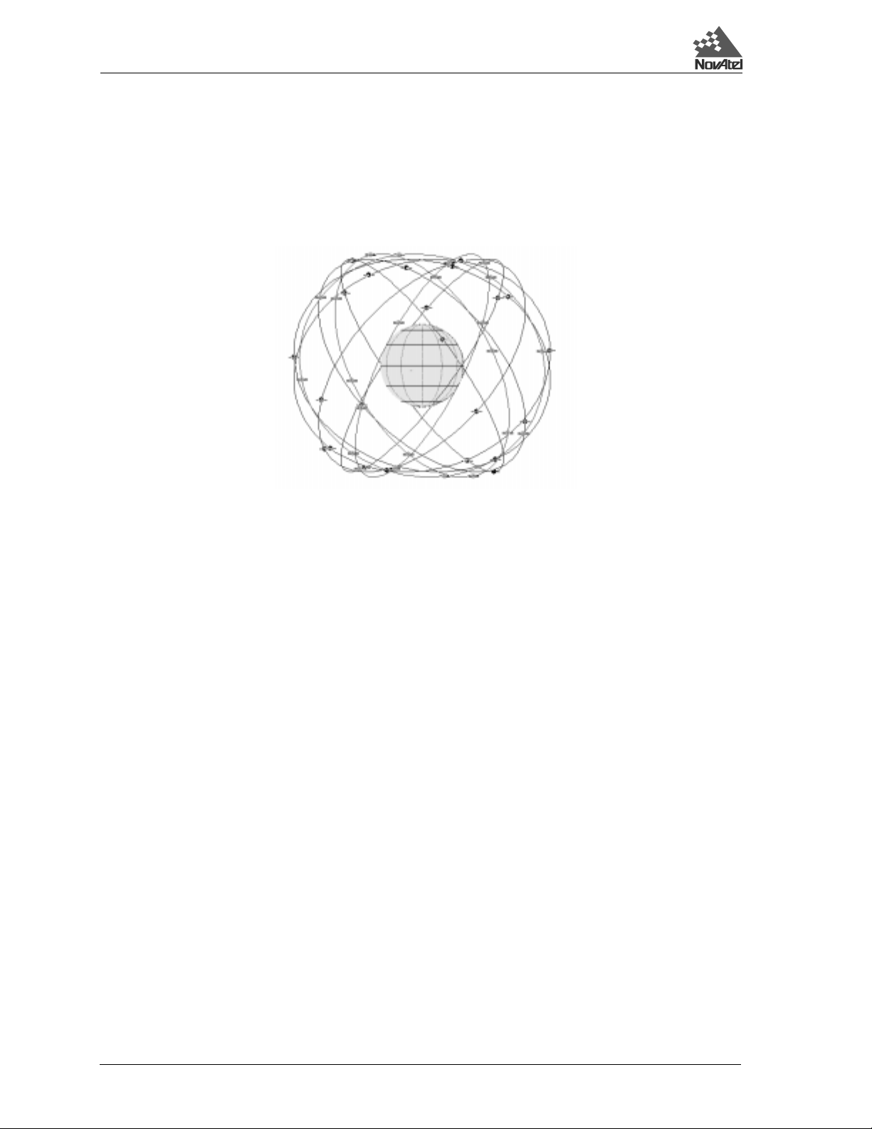
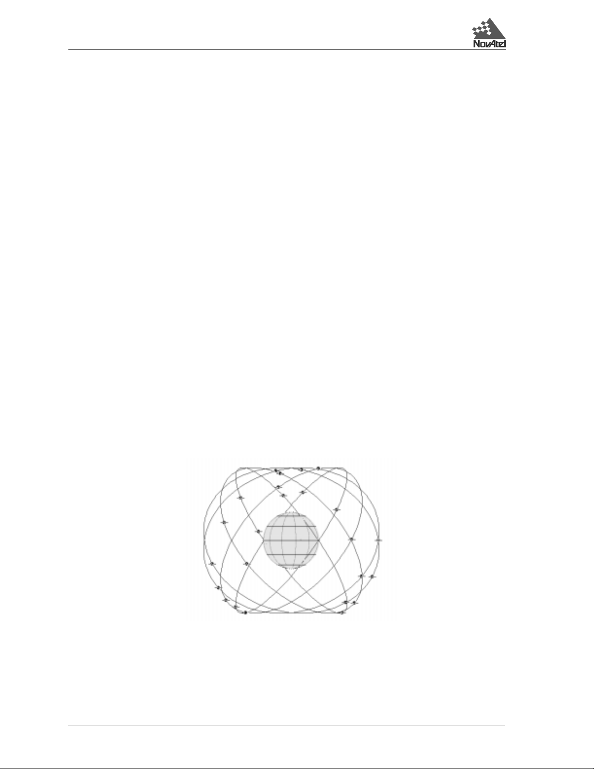
characteristics. Refer to Figure 1.1, Page 10 , for a representation of the GPS and GLONASS com bined satellite
orbit arrangement.
Figure 1.1 View of GPS and GLONASS Combined Satellite Orbit Arrangement
1.3 GPS SYSTEM DESIGN
The system uses the NAVSTAR (NAVigation Satellite Timing And Ranging) satellites which consists of 24
operational satellites to provide a GPS receiver with six to twelve-satellite coverage at all times depending on the
receiver model. A minimum of four satellites in view allows the GPSCard to compute its current latitude, lo ngitude,
altitude with reference to ellipsoid mean sea level an d the GPS system time.
The GPS system design consists of three parts:
• The Space segment
• The Control segment
• The User s egment
All these parts operate together to provide accurate three dimensional positioning, timing and velocity data to users
worldwide.
1.3.1 THE SPACE SEGMENT
The space segment is composed of the NAVSTAR GPS satellites. The final constellation of the system consists of
24 satellites in six orbital planes, inclined 55° from the equator, with four satellites in each plane. The orbital period
of each satellite is approximately 12 hours at an altitude of 20,183 km. This pr ovides a GPS receiver with six to
twelve satellites in view from any point on earth, at any particular time.
The GPS satellite signal identifies the satellite and p rovides the p ositioning, timin g, ranging data, sat ellite status
and ephemerides (orbit parameters) of the satellite to th e receiver. The satellites can be identified either by the
Space Vehicle Number (SVN) or the Pseudorandom Code Number (PRN). The PRN is used by the NovAtel
GPSCard.
The GPS satellites transmit on two L-band frequencies; one centered at 1575.42 MHz (L1) and the other at 1227.60
MHz (L2). The L1 carrier is modulated by the C/A code (C oarse/Acqu isitio n) and t he P cod e (Precision ) which
is encrypted for military and other authorized users. The L2 carrier is modulated only with the P code. Please refer
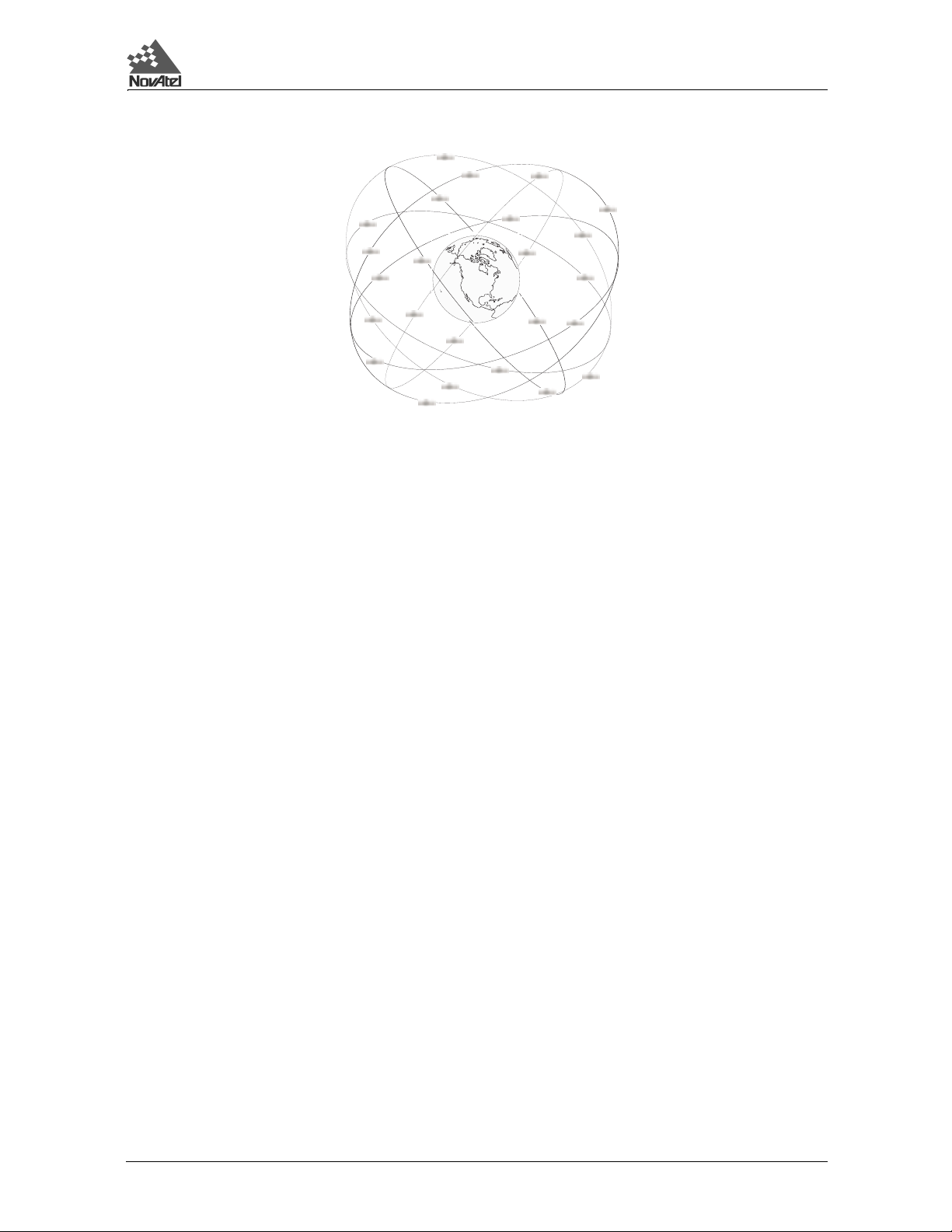
to the following figure for a representation of the GPS satellite orbit arrang e ment.
10 GPS/GLONASS Receiver User Manual Rev 1
1 Introduction
Figure 1.2 View of GPS Satellite Orbit Arrangement
1.3.2 THE CONTROL SEGMENT
The control segment consists of a master control station, five reference stations and three data up-loading stations
in locations all around the globe.
The reference stations track and monitor the satellites via their broadcast signals. The broadcast signals contain the
ephemeris data of the satellites, the ranging signals, the clock data and the almanac data. These signals are passed
to the master control station where the ephemerides are re-computed. The resulting ephemerides corrections and
timing corrections are transmitted back to the satellites via the data up-loading stations.
1.3.3 THE USER SEGMENT
The user segment such as the NovAtel GPSCard receiver, consists of equipment which tracks and receives the
satellite signals. The user equipment must be capa ble of simultaneo usly processing the sig nals from a minimum of
four satellites to obtain accurate position, velocity and timing measurements.
1.4 GLONASS SYSTEM DESIGN
As with GPS, the GLONASS system uses a satellite constellation to ideally provide a GLONASS receiver with six
to twelve satellites at most times. A minimum of four satellites in view allows a GLONASS receiver to compute
its position in three dimensions, as well as become synchronized to the system time.
The GLONASS system design consists of three parts:
• The Space segment
• The Control segment
• The User segment
All these parts operate together to provide accurate three dimensional positioning, timing and velocity data to users
worldwide.
1.4.1 THE SPACE SEGMENT
The Space Segment is the portion of the GLONASS system that is located in space, that is, the GLONASS satellites
and any ancillary spacecraft that provide GLONASS augmentation information (i.e., differential corrections,
integrity messages, etc.). This segment is composed of the GLONASS satellites which, when complete, will
consist of 24 satellites in three orbital planes, with eight satellites per plane, see Figure 1.3, Page 12. Following
are points about the GLONASS space segment.
GPS/GLONASS Receiver User Manual Rev 1 11
1 Introduction
• The orbit period of each satellite is approximately 8/17 of a sidereal day such that, after eight
sidereal days, the GLONASS satellites have completed exactly 17 orbital revolutions. A
sidereal day is the rotation period of the earth and is equal to one calendar day minus four
minutes.
• Because each orbital plane contains eight equally spaced satellites, one of the satellites will
be at the same spot in the sky at the same sidereal time each day.
• The satellites are placed into nominally circular orbits with target inclinations of 64.8
degrees and an orbital height of about 19,123 km, which is about 1,060 km lower than GPS
satellites.
• The GLONASS satellite signal identifies the satellite and provides:
• The GLONASS satellites each transmit on different L1 and L2 frequencies, with the P code
on both L1 and L2, and with the C/A code, at present, only on L1. L1 is currently centered at
1602 - 1615.5 MHz.
• Some of the GLONASS transmissions initially caused interference to radio astronomers and
mobile communication service providers. The Russians consequently agreed to reduce the
number of frequencies used by the satellites and to gradually change the L1 frequencies to
1598.0625 - 1609.3125 MHz. Eventually the system will only use 12 primary frequency
channels (plus two additional channels for tes t ing purposes).
• System operation (24 satellites and only 12 channels) can be accomplished by having
antipodal satellites, satellites in the same orbit plane separated by 180 degrees in argument
of latitude, transmit on the same frequency . This is possible because the paired satellites will
never appear at the same time in your view. Already, eight pairs of satellites share
frequencies.
• the positioning, velocity and acceleration vectors at a reference epoch f or computing
satellite locations
• synchronization bits
• data age
• satellite health
• offset of GLONASS time
• almanacs of all other GLONASS satellites.
Unlike GPS satellites, all GLONASS satellites transmit the same codes. They derive signal timing and frequencies
from one of three onboard cesium atomic clocks operating at 5 MHz. The signals are right-hand circularly
polarized, like GPS signals, and have comparable signal strength.
Figure 1.3 View of GLONASS Satellite Orbit Arrangement
1.4.2 THE CONTROL SEGMENT
The Control Segment consists of the system control center and a network of command tracking stations across
Russia. The GLONASS control segment, similar to GPS, must monitor the status of satellites, determine the
ephemerides and satellite clock offsets with respect to GLONASS time and UTC (SU) time, and twice a day upload
the navigation data to the satellites.
12 GPS/GLONASS Receiver User Manual Rev 1

1 Introduction
1.4.3 THE USER SEGMENT
The User Segment consists of equipment (such as a NovAtel MiLLennium-GLONASS GPSCard receiver) which
tracks and receives the satellite signals. This equipment must be capable of simultaneou sly pro cessing the signals
from a minimum of four satellites to obtain accurate position, velocity and timing measurements. Like GPS,
GLONASS is a dual military/civilian-use system. Selective availability, however, will not be imp lemented on
GLONASS C/A code. The system’s potential civil applications are many and mirror that of GPS.
1.5 TIME
As stated above, both GPS and GLONASS satellites broadcast their time within their satellite messages. NovAtel’s
MiLLennium-GLONASS GPSCard is able to receive and record both time references as well as report the offset
information between GPS and GLONASS time (see GCLA/B, Page 91). Although similar, GPS and GLONASS
have several differences in the way they record and report time. Please see the following sections for information
on GPS and GLONASS time, as well as how NovAtel’s MiLLennium-GLONASS GPSCard is GPS week r ollover
and Y2K compliant.
1.5.1 GPS TIME VS. LOCAL RECEIVER TIME
All logs report GPS time expressed in GPS weeks and seconds into the week. The time reported is not corrected
for local receiver clock error. To derive the closest GPS time, you must subtract the clock offset shown in the
CLKA/B log (field 4) from GPS time reported, refer to the MiLLennium Command Descriptions Manual.
GPS time is based on an atom ic tim e scale. Un iversa l Time C oordi nated U.S . Naval Ob servatory (UTC(USNO))
time (reported in NMEA logs) is also based on an atomic time scale, with an off set of seconds applied to coordinate
Universal Time to GPS time. GPS time is designated as being coincident with UTC(USNO) at the start date of
January 6, 1980 (00 hours). GPS time does not count leap seconds, and therefore an offset exists between
UTC(USNO) and GPS time (at this date: 13 seconds). The GPS week consists of 604800 seconds, where 000000
seconds is at Saturday midnight. Each week at this time (UTC), the week number increments by one, and the
seconds into the week resets to 0 (see Appendix C, Page 54 for an example).
1.5.2 GLONASS TIME VS. LOCAL RECEIVER TIME
GLONASS time is based on an atomic time scale similar to GPS. This time scale is U niversal Time Coordinated
as maintained by the former Soviet Union (UTC(SU)).
Unlike GPS, the GLONASS time scale is not continuous and must be adjusted for periodic leap seconds. Leap
seconds are applied to all UTC time references about every other year as specified by the International Earth
Rotation Service (IERS). Leap seconds are necessary because the orbit of the earth is not uniform and not as
accurate as the atomic time references.
GLONASS time is maintained within 1 ms of UTC(SU) by the control segment with the remaining portion of the
offset broadcast in the navigation message. As well, the GLONASS time is offset from UTC(SU) by plus three
hours due to control segment specific issues. The GCLA/B (see Page 91) contains the offset information between
GPS and GLONASS time.
1.6 DATUM
Because a consistent transformation between WGS84 and the Parametry Zemli 1990 (PZ90) or, in English
translation, Parameters of the Earth 1990 (PE-90, see Page 120) geodetic datum has not been defined, we have
allowed for a new command, PZ90TOWGS84, and a new parameter, PZ90, for the DATUM command.
The PZ90TOWGS84 command (see “G.1.2 PZ90TOWGS84”, Page 82) is intended to define the PZ90 transform
for transferring Glonass satellite coordinates to WGS84. Ho wever, it can also be used, in conjunction with the
DATUM PZ90 command (see “G.2.6 DATUM”, Page 85), to allow for position output in a user-defined PZ90
frame. The PZ90TOWGS84 command will override the default values for the DATUM PZ90 command and set
them to the user-defined values. If the PZ90TOWGS84 com mand is not issued, the DATUM PZ90 command will
use the default PZ90 values (see “G.1 .2 PZ90TOW GS84”, Pa ge 82) for the outp ut positi on paramete rs. The PZ90
transform parameters can be saved in user-configurable memory for immediate use on powerup.
GPS/GLONASS Receiver User Manual Rev 1 13

1 Introduction
Table 1.2 Comparison of GLONASS and GPS Characteristics
Parameter Detail GLONASS GPS
Satellites Number of satellites 21 + 3 spares 21 + 3 spares
Number of orbital p lanes 3 6
Orbital plane inclination (degree s) 64.8 55
Orbital radius (kilometers) 25 510 26 560
Signals Fundamental clock frequ en c y ( MH z ) 5.0 10.23
Signal separation technique
1
Carrier frequencies (MHz) L1 1602.0 - 1615.5 1575.42
Code clock rate (MHz) C/A 0.511 1.023
P 5.11 10.23
Code length (chips) C/A 511 1 023
P
C/A-code Navigation Superframe duration (minutes) 2.5 12.5
Message
Superframe capacity (bits) 7 500 37 500
Superframe reserve capacity (bits) ~620 ~2 750
Word duration (s econds) 2.0 0.6
Word capacity (bits) 100 30
Number of words within a frame 15 50
Technique for specifying satellite
ephemeris
Time reference
Position reference (geodatic datum)
1
Each satellite in the full 24-satellite GLONASS constellation is assigned an antipodal frequency. Such a system of simultaneous multiple
transmissions is known as frequency division multiple access (FDMA) and distinguishes GLONASS from GPS, which is a code division multiple
access (CDMA) system.
2
GLONASS and GPS use different time systems. GLONASS time is referenced to UTC (SU), the Russian National Etalon timescale, whereas, GPS
time is referenced to UTC as maintained by the U.S. Naval Observatory – UTC (USNO). The GLONASS control segment periodically applies a
time step to bring the system’s time within several hundred nano-seconds of UTC time.
3
GLONASS ephemerides are referenced to the Parametry Zemli 1990 (PZ-90 or in English translation, Parameters of the Earth 1990, PE-90)
geodetic datum. The realization of the PZ-90 frame through adopted reference station coordinates has resulted in offsets in origin and orientation as
well as a difference in scale with respect to WGS 84 used by GPS. Relationships between the PZ-90 and WGS 84 have now been established.
2
3
NOTES:
FDMA CDMA
5.11 x 10
Geocentric Cartesian
coordinates and their
derivatives
6
6.187104 x 10
Keplarian orbital
elements and
perturbation facto r s
UTC (SU) UTC (USNO)
PZ-90 WGS 84
12
14 GPS/GLONASS Receiver User Manual Rev 1
2 Quick Start
2 QUICK START
2
QUICK START
2.1 QUICK START STEPS
The total system consists of a combined GPS/GLONASS receiver, an antenna, cables and your PC.
1. Prepare the MiLLennium-GLONASS GPSCard so that it is complete with mounting and wiring
interfaces and ready for operation, as described in Chapter 3, Installatio n, Page 17. If you purchased a
ProPak II enclosure (see Page 59) or a PowerPak II enclosure (see Page 73), they are ready for immediate
operation.
2. Mount the antenna. See GPS/GLONASS Antenna Considerations (Page 23), GPS/GLONASS Antenna
(Page 56) and RF Section (Page 57).
3. Connect the antenna to the RF port of the ProPak II enclosure, PowerPak II enclosure or P101 connector
on the MiLLennium-GLONASS GPSCard, see Figure 3.1, Typic al System Configura tion (Page 17 ) and
Figure E.3, ProPak II Enclosure Re ar End-Cap (Page 60), using interconnecting co axial cable. A typical
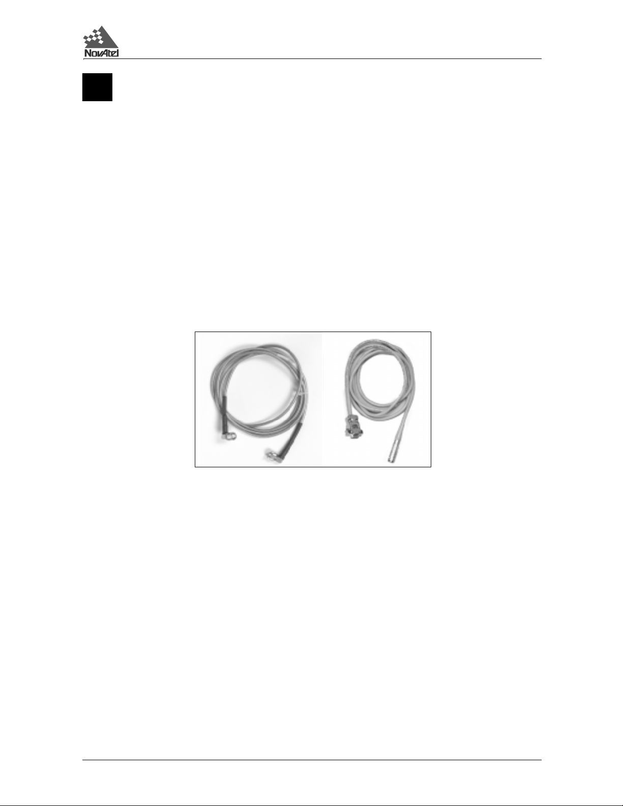
coaxial cable is shown in Figure 2.1 on the left.
Figure 2.1 NovAtel Coaxial and Serial Cables
For more information see Antenna Cable Considerations (Page 23) and RF Section (Page 57).
4. Connect COM1 on the receiver to a serial port on your PC with a null-modem serial data cable (NovAtel
part number 01016329). A typical serial cable is shown in Figure 2.1, on the right. See also Chapter 4,
Operation (P age 24 ), Digital Electronics Section (Page 57) and ProPak II Enclosure Installation (Page
59).
5. Connect a power supply to the MiLLennium-GLONASS. The ProPak II enclosure is supplied with a
LEMO to cigarette lighter power adapter cable. If an alternative power source is preferred, the cigarette
lighter power cable adapter can be removed. When the adapter is cut off, and the cable stripped, it will be
observed that two leads are provided for each positive (+) and negative (-) connection. This allows for
parallel power sources such as dual batteries. The DC power must be in the ran ge f rom +10 to +3 6 V DC
and the use of a 3-amp slow-blow fuse is recommended, perhaps the one from the cigarette lighter power
adapter if you do not intend to use it. See Preparing the Data, Signal & Power Har ness (Page 19),
Principal Power Supply (Page 57) and ProPak II Enclosure Installation (P age 59).
6. Start GPSolution on your PC. Select Card | Open from the menu. To connect to the MiLLennium-
GLONASS in GPSolution you must open a configuration. A configuration is a group of settings that
define the type of card, the communication protocol, window positions and file locations. The Open
Configuration dialog will appear. All created configurations are displayed in the listbox. Choose a
configuration from the list and cl ick the OK button. If there are no configuratio ns available you must
create a new configuration. GPSolution will attempt to open MiLLennium-GLONASS using the
specifications in the selected configuration. The MiLLennium-GLONASS default port settings are as
follows:
RS232C, 9600 bps, no parity, 8 data bits, 1 stop bit, no handshaking, echo off
GPS/GLONASS Receiver User Manual Rev 1 15

2 Quick Start
See Communications with the MiLLennium-GLONASS GPSCard, Page 24.
7. Select View | Command Console and then View | ASCII Records fr om the menu. You may also open o ther
visual displays from the View menu at any stage. See Getting Started, Page 25.
8. If high-accuracy GLONASS pseudoranges are desired, run the calibration procedure. See Cal ibration
Procedure, Page 27.
16 GPS/GLONASS Receiver User Manual Rev 1

3Installation
3 INSTALLATION
3Installation
3.1 SYSTEM CONFIGURATION
The MiLLennium-GLONASS GPSCard receiver is an OEM product designed for flexibility of integration and
configuration. You are free to select an appropriate data and signal interface, power supply system, and mounting
structure. This concept allows OEM purchasers to custom-design th eir own applications around the MiLLenniumGLONASS.
It also comes in a ProPak II enclosure or PowerPak II enclosure, please see ProPak II Enclosur e (Page 59) or
PowerPak II Enclosure (Page 73).
This section provides the necessary information for you to install and begin to use the MiLLennium-GLONASS
GPSCard. A typical system configuration is shown in Figure 3.1.
Figure 3.1 Typical System Configuration
1
3
6
4
7
8
2
9
10
11
5
13
Reference Description Reference Description
1 ProPak II enclosure, PowerPak II enclosure 8 Optional LNA DC power (1 pin)
2 RF sign al & LNA power SMB connector P101 10 COM2 (8 pins)
(male, right angle) to antenna via 11 Input & output timing strobes
3 Optional external reference clock input SM B 12 Matching user- supplied
4 Power, data & signals connector, P1 (male, 13 Optional choke ring ground pl ane
5 Status LEDs (green & red) with 5/8” adapter or an y NovAtel
6 LNA power jumper P301,
7 +5 VDC primary power
or user-supplied enclosure 9 COM1 (8 pins)
interconnecting coaxial cable (12 pins)
connector P301 (male, straight) interface i.e. matches item #4
64-pin, 0.1”, DIN 41 612, Type B, right angle) 14 Antenna model 504 shown
see the External L1 GPS/GLONASS antenna
Power section, Page 21
14
12
GPS/GLONASS Receiver User Manual Rev 1 17

3 Installation
3.2 MINIMUM CONFIGURATION
In order for the MiLLennium-GLONASS GPSCard to perform optimally, the following additional equipment is
required:
• NovAtel GPS/GLONASS antennas (model 504 or model 514)
• NovAtel coaxial cable (note that a conversion is required between the male SMB connector
on the MiLLennium-GLONASS GPSCard and the female TNC connector on the GPS/
GLONASS antenna)
• A regulated power supply providing +5 V DC (see Table B.1, Page 49, for p ower regu lation
specifications)
• A 64-pin 0.1" DIN 41612 Type B female connector as an interface for power,
communications and signals
• Data communications equipment capable of RS-232C serial communications
3.3 ANTI-STATIC PRECA UTIONS
Electrostatic discharge (ESD) is a leading cause of failure of electronic equipment components and printed circuit
boards containing ESD-sensitive devices and components. It is imperative that ESD precautions be followed when
handling or installing the MiLLennium-GLONASS GPSCard printed circuit board. See Appendix A, Page 47, for
more information on ESD precautions.
Leave the MiLLennium-GLONASS GPSCard in its anti-static packaging when not connected in its normal
operating environment. When removing the MiLLennium-GLONASS GPSCard from the ESD-protective plastic
clamshell, follow accepted standard anti-static practices. Failure to do so may cause damage to the card.
When you remove the MiLLennium-GLONASS GPSCard from the original packing box, it is recommended that
you save the box and ESD protective plastic clamshell for future storage or shipment purposes.
REMEMBER
• Always wear a properly grounded anti-static wrist strap when handling the MiLLennium-GLONASS
GPSCard.
• Always hold the MiLLennium-GLONASS GPSCard by its corners or the RF backplane, and avoid direct
contact with any of the components.
• Do not let the MiLLennium-GLONASS GPSCard come in contact with clothing at any time because the
grounding strap cannot dissipate static charges from fabrics.
• Failure to follow accepted ESD handling practices could cause damage to the MiLLennium-GLONASS
GPSCard.
• Warranty may be voided if equipment is damaged by ESD.
3.4 INSTALLATION PROCEDURE
Installing the MiLLennium-GLONASS GPSCard typically consists of the following:
• mounting the MiLLennium-GLONASS GPSCard in a secure enclosure to reduce
environmental exposure, RF interference, and vibration effects
• pre-wiring the I/O harness and the 64-pin DIN female connector for power and
communications, then connecting them to the MiLLennium-GLONASS GPSCard
• installing the GPS/GLONASS antenna, then connecting it to the MiLLennium-GLONASS
GPSCard
• installing an optional external oscillator (see Page 80)
18 GPS/GLONASS Receiver User Manual Rev 1

3Installation
3.4.1 MOUNTING THE PRINTED CIRCUIT BOARD
The MiLLennium-GLONASS GPSCard is an OEM product and therefore the printed circuit board is not enclosed
in a housing structure. This allows flexibility in creating a mo unting environment to suit particular product and
marketing requirements. The mounting and enclosure must provide the following:
• mounting of external connectors
• protection from hostile physical environments (e.g. rain, snow, sand, saltwater, extreme
temperatures)
• protection from vibration condi t ions
• electromagnetic shielding to protect from hostile RF environments (e.g. nearby transmitters)
• electromagnetic shielding so that the final product itself conforms to RF emissions guides
• protection from ESD
The MiLLennium-GLONASS GPSCard can be screwed in place, held by card rails, or both. Please see Appendix
B, Page 49, for mechanical drawings.
For some applications the ProPak II Encl os ur e, Page 59, or the PowerPak II Enclosure, Page 73, in the chapters
following, are ideal. They are enclosure kits that come complete with mounting and wiring interfaces, and allow
immediate operation of the MiLLennium-GLONASS. The two enclosures are designed for rugged operating
environments.
3.4.2 PREPARING THE DATA, SIGNAL & POWER HARNESS
The wiring harness serves the following interconnect functions:
• provide access to COM1 and COM2 serial communications ports
• provide access to input and output timing strobes
• provide power input(s)
• provide access to control signals
A 64-pin / 0.1" / DIN 41612 / Type B / female connector (e.g. Harting #0902 164 6825, #0902 264 6828, or
equivalent) is required to interface with connector P1 on the MiLLennium-GLONASS GPSCard (see Figure 3.2,
Page 20). The connectors you choose for interfacing to the powe r source(s), COM ports, and st rob es will depen d
on your external equipment requirements. Figure 3.2, Page 20 shows the pin names and locations on connector
P1.
NOTE: See Table B.2, Page 53, for descriptions of the function of each connector pin.
WARNING: The MiLLennium-GLONASS GPSCard will suspend operation if voltage supplied falls outside
input range +4.875 to +5.250 V DC.
GPS/GLONASS Receiver User Manual Rev 1 19
3 Installation
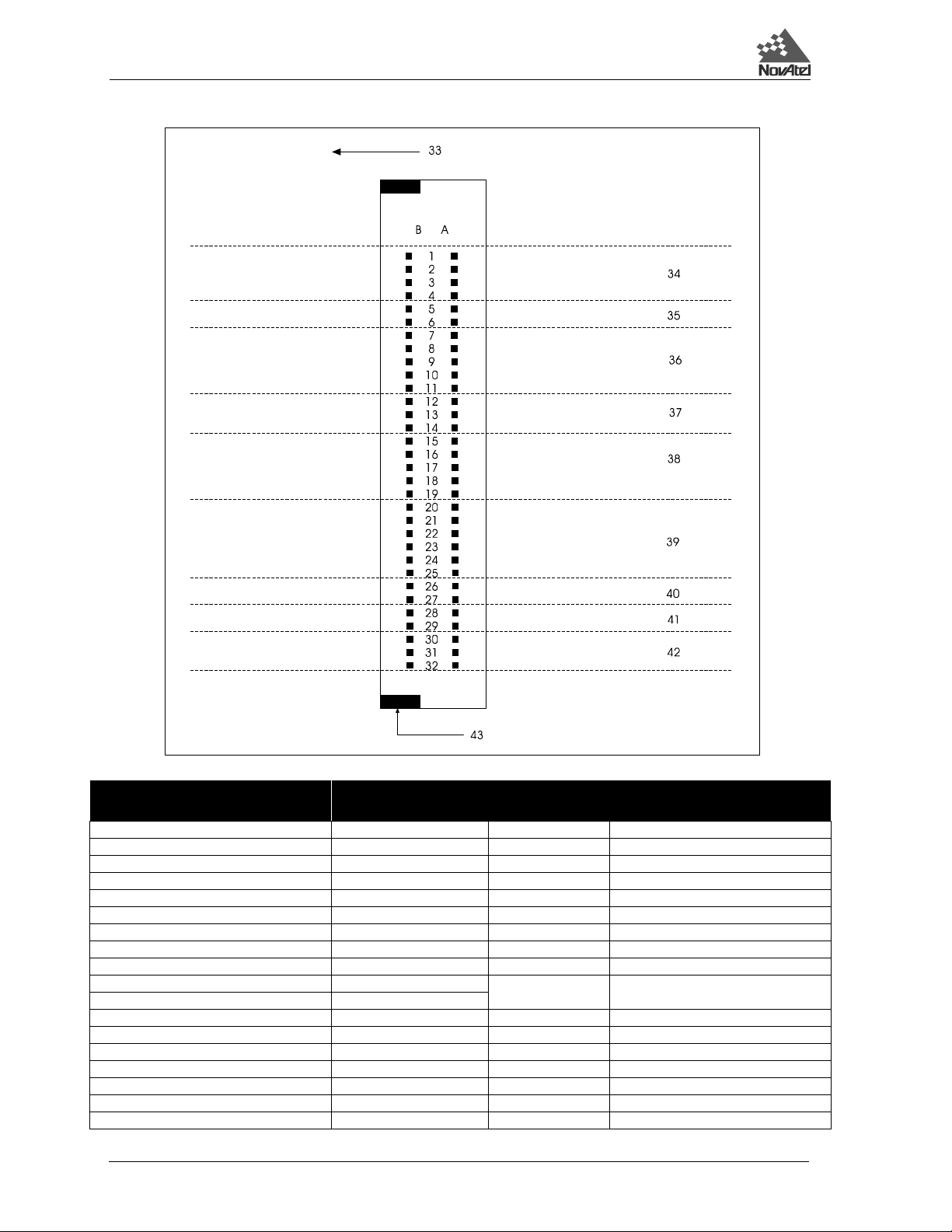
Figure 3.2 Edge-view of Connector P1 on the MiLLennium-GLONASS
PIN NUMBER Description
1A, 1B, 4A, 7A,15A, 21A-32A GND 19A DCD2
2A, 2B Vcc 19B DSR2
3A, 5B-8B, 12A, 12B-16B, 20A, 20B N/C 21B VARF
3B Reserved for future use 22B PPS
4B External LNA power 23B Measure out
5A, 6A, 13A, 14A, 26B, 27B, 30B-32B Factory use 24B Mark in
8A DTR 1 25B Status
9A TXD1 28B Reset in
9B CTS1 29B Reset out
10A RXD1 33 Component side of
10B RTS1 MiLLennium-GLONASS GPSCard
11A DCD1 34 Power
11B DSR1 35, 37, 40, 42 Factory use
16A DTR2 36 COM1 (RS-232C)
17A TXD2 38 COM2 (RS-232C)
17B CTS2 39 Strobes
18A RXD2 41 Control
18B RTS2 43 Keying tab
PIN NUMBER
Description
20 GPS/GLONASS Receiver User Manual Rev 1
3Installation
3.4.3 EXTERNAL POWER
See Figure 3.2, Page 20 for external power input connections:
• Digital ground = pins 1A/B (internally connected)
• Vcc, main power (+5 V DC) = pins 2A/B (internally connected)
• Optional external LNA power = pin 4B (30 V DC) and 4A (GND)
See Table B.1, Page 49, for specifications concerning external power inputs.
The MiLLennium-GLONASS GPSCard requires only one regulated power input of Vcc = +5 V DC.
It is possible to supply power to the LNA on an active antenna either fro m the MiLLenniu m-GLONASS GPSCard
or from an external source. The MiLLennium-GLONASS GPSCard is factory-configured for operation with the
single-frequency 504 or 514 GPS/GLONASS antenna models, in which case no special wiring or configuration is
required: the P301 jumper (s ee Figure 3.1 (Page 17) and Fi gure 3.3 following) is normally set for internal
(connects pins 1 and 2). The internal antenna power supply can produce 4.25 - 5.25 V DC at up to 90 mA. If the
antenna draws more than 90 mA of current, power to th e antenn a will be d isabled and the ant enna self-test statu s
flag set to zero; see Appendix H, RVSA/B log (Page 109) and Table H.2 (Page 96) for receiver self-test status codes.
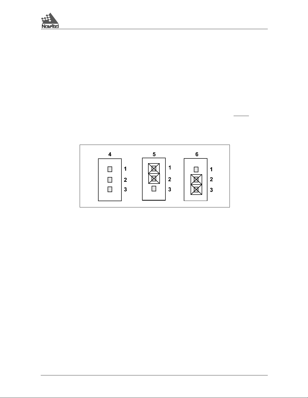
Figure 3.3 LNA Power Jumper P301 - 3 Cases
operation
Reference Description
1Pin 1
2Pin 2
3Pin 3
4 Case 1: No power to LNA
5 Case 2: Intern al power source (default)
6 Case 3: Extern al power source
If a different antenna is used whose LNA requires voltage and/or current capacity beyond what the MiLLenniumGLONASS GPSCard can produce, then the external LNA power option must be utilized - this requires that P301
must be jumpered between pins 2 and 3. The input cannot exceed +30 V D.C. at 100 mA. When the LNA jumper
plug is in the external position, th e antenna sensing circuit will cause the self-test status code to always report
antenna status as 1 (good). See Appendix H, RVSA/B log (Page 109) and Ta ble H.2 (Pa ge 96) for receiver self-test
status codes.
If no LNA power is required, remove the jumper at P301 completely.
In contrast to the physical jumper settings, it is the ANTENNAPOWER command which actually enables or
disables the supply of electrical power from the internal power source of the card to Pin 1 of jumper P301. By
default, ANTENNAPOWER = ON. Table 3.1, Page 22 illustrates the usage of this command in relation to the
jumper position.
The setting of this command will also affect the way the self-test diagnostics report the antenna’s status; please see
the description of the ANTENNAPOWER command, Page 84.
GPS/GLONASS Receiver User Manual Rev 1 21

3 Installation
Table 3.1 Antenna LNA Power Configuration
P301: plug connects pins
1&2
ANTENNAPOWER = ON internal power connected to LNA no external effect no external effect
ANTENNAPOWER = OFF internal power cut off from LNA no external effect no external effect
CAUTION
• The P301 jumper plug must be jumpered to the external position (pins 2 and 3) before
LNA power is connected to pin 4B of the 64-pin wire harness con nector t o prev ent power fro m
feeding back into the receiver.
• Should it be necessary, due to extended length antenna cable, to supply external power to the
GPS/GLONASS antenna or to use an optional in-line LNA amplifier, be careful not to exceed
the voltage ratings of either the antenna or LNA.
• No guarantee is made that the MiLLennium-GLONASS GPSCard will meet its performance
specifications if a non-NovAtel antenna is used.
It is recommended that appropriate fuses or current limiting be incorporated as a safety precaution on all power
lines used. Use a sufficient gauge of wire, fo r examp le AWG 24 , to en sure that th e v oltage at th e 6 4-pin co nne ctor
is within the MiLLennium-GLONASS GPSCard’s requirements.
P301: plug connects pins
2&3
P301: no plug
external
3.4.4 RS232C COMMUNICATIONS
The MiLLennium-GLONASS GPSCard is capable of communications in EIA RS232C serial data format via two
ports, COM1 and COM2. See Figure 3.2, Page 20 for data connections:
• COM1 = pins 7 - 11, A & B
• COM2 = pins 15 - 19, A & B
Each port has a ground connection, and supports the following signals:
• Data Terminal Ready (DTR)
• Clear To Send (CTS)
• Transmitted Data (TXD)
• Request To Send (RTS)
• Received Data (RXD)
• Data Set Ready (DSR)
• Data Carrier Detect (DCD)
The port settings (bit rate, parity, etc.) are software-configurable. These are further described in Chapter 4,
Operation, Page 24.
See Table B.2, Page 53, for further information on data communications characteristics.
3.4.5 STROBE SIGNALS
The MiLLennium-GLONASS GPSCard has 5 TTL-compatible I/O strobe lines. See Figure 3 .2, Page 20 f or strobe
signal connections:
• Variable-Frequency (VARF) Output = Pin 21B
• One Pulse per Second (PPS) Output = Pin 22B
• Measure Output = Pin 23B
• Mark Input = Pin 24B
• Status Output = Pin 25B
See Table B.1, Page 49, for further information on I/O strobe characteristics.
22 GPS/GLONASS Receiver User Manual Rev 1

3Installation
3.4.6 L1 GPS/GLONASS ANTENNA CONSIDERATIONS
The MiLLennium-GLONASS GPSCard has been designed to operate with the NovAtel 504 or 514 singlefrequency GPS/GLONASS antenna models. Though it is possible to operate with other single-frequency GPS/
GLONASS antennas, no guarantee is made that the MiLLennium-GLONASS GPSCard will meet its performance
specifications if a non-NovAtel antenna is used. For further information on GPS/GLONASS antenna systems and
extended length cable runs, contact NovAtel Customer Service.
The NovAtel L1 GPS/GLONASS antennas, models 504 and 514, are active antennas designed to operate at the
GPS and GLONASS L1 frequency. The 504 antenna is intended for surveying and other kinematic positioning
applications, and the 514 is an aviation antenna that is ideally suited for installation on aircraft. For more
information on the model 504 antenna please refer to the NovAtel L1 GPS/GLONASS Antenna Model 504 Brochure
(NovAtel part number OM-20000037), and for more information on the model 514 antenna please refer to the
NovAtel L1 GPS/GLONASS Antenna Model 514 Brochure (NovAtel part number OM-20000038).
When installing the antenna system,
• choose an antenna location that has a clear view of the sky so that each satellite above the
horizon can be tracked without obstruction. (For a discussion on multipath, refer to the
relevant appendix in the MiLLennium Command Descriptions Manual.)
• mount the antenna on a secure, stable structure capable of safe operation in the specific
environment.
3.4.6.1 Antenna Cable Considerations
An appropriate coaxial cable is one that is matched to the impedance of the antenna being used, and whose line
loss does not exceed the recommendations shown in Table 3.2, Page 23. NovAtel offers a variety of coaxial cables
to meet your single-frequency GPS /GLONASS antenna i nterco nnect ion re quirem e nts. Your local NovAtel dealer
can advise you about your specific configuration.
NovAtel provides optional coaxial cables in the following lengths:
• 22 cm interconnect adapter cable (SMB female/TNC bulkhead - female; NovAtel part
number GPS-C001)
• 5, 15, or 30 m anten na cab l e (TNC mal e/ TNC male; NovAtel part numbers C005, C015 and
C030 respectively)
Though it is possible to use other high-quality antenna cables, no warrant is made that the MiLLenniumGLONASS GPSCard will meet its performance specifications if non-NovAtel-supplied coaxial cable is used.
Table 3.2 Recommended Maximum Cable Loss
Antenna Type Allowable Cable Loss
Active 13.0 dB
Passive 1.5 dB
NOTE: The coaxial cable should be connected to the antenna and MiLLennium-GLONASS GPSCard before
system power is turned on. If for any reason the cab le is disconnected from either the antenna or receiver,
you must turn off power before reconnecting the cable(s) otherwise the MiLLennium-GLONASS
GPSCard will not be able to sense the antenna and the system will not work. If this occurs, remove power
from the receiver, wait a few moments, and then apply it again.
GPS/GLONASS Receiver User Manual Rev 1 23

4 Operation
4 OPERATION
4 OPERATION
4.1 BEFORE OPERATION
Before operating the MiLLennium-GLONASS for the first time, ensure that you have followed the installation
instructions of Chapter 3. The following instructions are based on a configuration such as that shown in Figure
4.1. It is assumed that a personal computer is used during the initial operation and testing for greater ease and
versatility.
Figure 4.1 Typical Operational Configuration
10
1
5
7
2
6
3
4
8
11
9
12
Reference Description Reference Description
1 Model 504 or 514 Antenna 7 COM1
2 Combined GPS/GLONASS Signal Input 8 COM2
3 Optional External Oscillator 9 Power
4 Clock Reference Station
5 GPS Card ProPak II or 11 Data Logger or
6 MiLLennium-GLONASS GPSCard 12 External Power Source
(not available with ProPa k II enclosure) 10 Command Source or
PowerPak II enclosure Remote Station
4.2 COMMUNICATIONS WITH THE MILLENNIUM-GLONASS
GPSCARD
Communication with the MiLLennium-GLONASS GPSCard is straightforward, and consists of issuing commands
through the COM1 or COM2 port from an externa l serial commun ica tions device. This could be either a ter minal
or an IBM-compatible PC that is directly connected to a MiLLennium-GLONASS GPSCard serial port using a null
modem cable. For specific information about any of the GPSCard commands and logs, please consult the
MiLLennium Command Descriptions Manual.
24 GPS/GLONASS Receiver User Manual Rev 1

4Operation
4.2.1 SERIAL PORT DEFAULT SETTINGS
The MiLLennium-GLONASS GPSCard communicates with your PC or terminal via the COM1 or COM2 serial
port. For communication to occur, bo th the MiLL ennium-GLONASS GPSCard and the operator interface have to
be configured properly. The MiLLennium-GLONASS GPSCard’s default port settings are as follows:
RS232C, 9600 bps, no parity, 8 data bits, 1 stop bit, no handshaking, echo off
Changing the default settings requires using the COMn command, which is described in the MiLLennium
Command Descriptions Manual. It is recommended that you become thoroughly familiar with these commands
and logs to ensure maximum utilization of the MiLLennium-GLONASS GPSCard’s capabilities.
NOTE: Although the MiLLennium-GLONASS GPSCard can operate at bit rates as low as 300 bps, this may
not always be desirable. For example, if several data logs are active (i.e. a significant amount of
information needs to be transmitted every second) but the bit rate is set too low, data will overflow the
serial port buffers and cause an error condition in the receiver status.
4.2.2 COMMUNICATING USING A REMOTE TERMINAL
One method of communicating with the MiLLennium-GLONASS GPSCard is through a remote terminal. The
MiLLennium-GLONASS GPSCard has been pre-wired to allow proper RS232C interface with your data termin al.
To communicate with the terminal the MiLLennium-GLONASS GPSCard only requires the RX, TX, and GND
lines to be used; handshaking is not required, although it can optionally be used. Ensure that the termin al’s
communications set-up matches the MiLLennium-GLONASS GPSCard RS232C protocol.
4.2.3 COMMUNICATING USING A PERSONAL COMPUTER
An IBM-compatible PC can be set up to emulate a remote terminal as well as provide the added flexibility of
creating multiple-command batch files an d data logging storage files. Any standard communications software
package that emulates a terminal can be used to establish bi-directional communications with the MiLLenniumGLONASS GPSCard.
You can create command batch files using any text editor; these can then be directed to the serial port that is
connected to the MiLLennium-GLONASS GPSCard using a communications software package. This is discussed
in greater detail later in this chapter.
4.3 GETTING STARTED
Included with your MiLLennium -GLONASS GPSCard are NovAtel’s GPSol ution, Convert and Loader programs,
together with their on-line help. GPSolution is a Microsoft Windows compatible program that allows you to access
the MiLLennium-GLONASS GPSCard's many features without struggling with communications protocol or
writing special software. GPSolution automati cally recognizes the model type of the MiLLennium-GLONASS
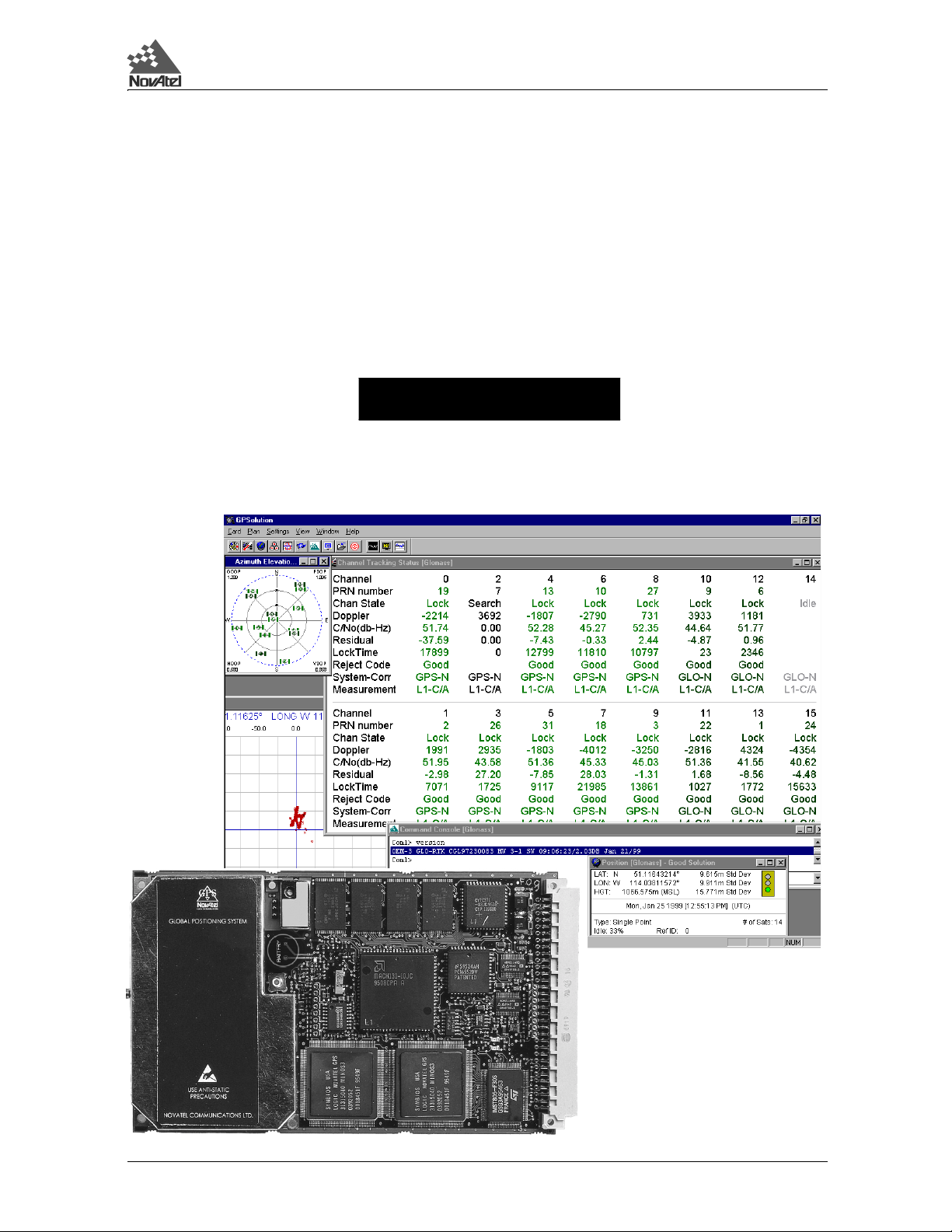
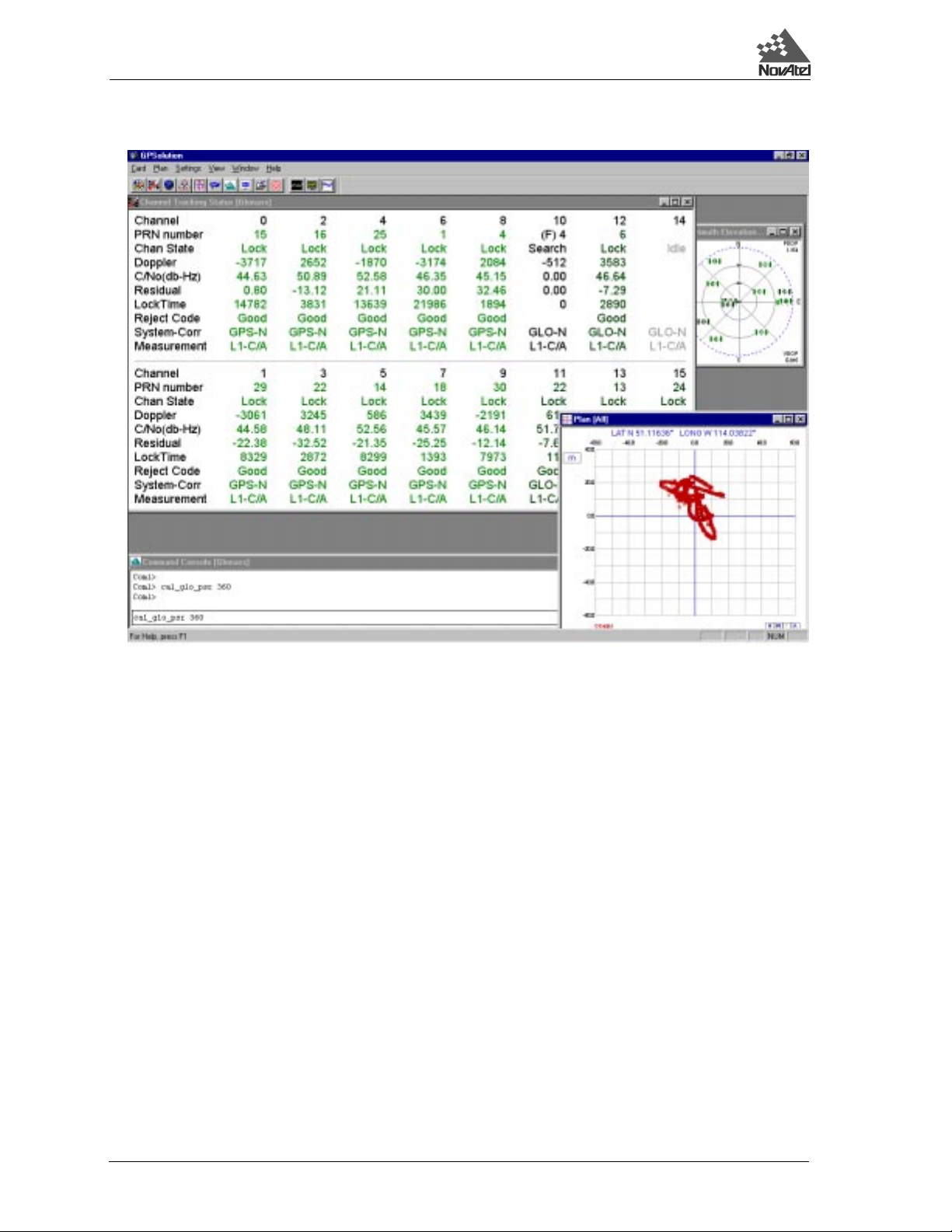
GPSCard that you are using and adjusts the displays accordingly. Figure 4.2 shows a sample GPSolution screen.
The Convert utility is a Windows-based utility that allows you to convert between NovAtel ASCII and binary file
formats, and strips unwanted records for data file compilation. NovAtel’s Loader program is a DOS utility program
designed to facilitate program and model updates.
GPS/GLONASS Receiver User Manual Rev 1 25
4 Operation
Figure 4.2 Sample GPSolution Screen
GPSolution is provided to facilitate your interaction with the MiLLennium-GLONASS GPS Card. However, it
certainly is possible to com municat e with it th rough DOS or a Wi ndows-bas ed commu nications program; this is
discussed in greater detail later in this section.
4.3.1 POWER-ON
The GPSCard’s software resides in read-only memory. As such, the unit “self-boots” when turned on and
undergoes a complete self-test. If an error condition is detected during a self-test, the self-test st atus word will
change; this self-test status word can be viewed in the RGEA/B/D and RVSA/B data output logs (please refer to
the MiLLennium Command Descripti ons Manual). If a persisten t error develops, please contact y our local NovAtel
dealer first. If the problem is still unreso lved please contact NovAt el directly through any of th e methods in the
Customer Service section, Page 7.
When the GPSCard is first turned on, no activity information is transmitted from the COM ports except for the port
prompt; the external data communications equ ipment screen will display one of these two messages:
Com1> if connected to COM1 port,
or
Com2> if connected to COM2 port
Either prompt indicates that the GPSCard is ready and waiting for command input.
Commands are typed at the interfacing terminal’s keyboard, and sent after issuing a carriage return command
which is usually the same as pressing the termin al’s Return or Enter key.
26 GPS/GLONASS Receiver User Manual Rev 1

4Operation
NOTE: Most valid commands do not echo a response to a command input; the indication that they have been
accepted is a return of the port prompt from the GPSCard. VERSION, HELP and ? are the only commands that do
provide a data response other than the port prompt.
The LOCKOUT and SETHEALTH commands are not for use with GLONASS satellites.
Example:
An example of no echo response to an input command is the ASSIGN command. It can be entered as follows:
COM1>assign 4 120043[Return]
COM1>
The above example illustrates command input to the MiLLennium-GLONASS GPSCard’s COM1 port which will
cause the card to assign the s atellite with frequency 12 and slot n umber 43 to channel 14. However, your only
confirmation that the command was actually accepted is the return of the COM1> prompt.
If a command is incorrectly entered, the GPSCard will respond with “Invalid Command Name” (or a more detailed
error message) followed by the port prompt.
After initially turning on the MiLLennium-GLONASS GPSCard, you may find the following logs useful for
observing the MiLLennium-GLONASS GPSCard’s activities. While GPSolution is the easiest way to do this, you
can also use DOS or a Windows-based communications prog ram; examples of both are provided below.
• Use the RCCA log to list the default command settings. The RCCA log is useful for
indicating status of all current command settings. Displaying the RCCA log after a RESET
will show the saved configuration (Refer to the description of the SAVECO NFIG command
in the MiLLennium Command Descriptions Manual for more information).
• Use the ETSA log to monitor the channel tracking status.
• Use the SATA log to observe the satellite sp ecific data.
• Use the POSA log to observe the current computed position solutions.
• Use the DOPA log to monitor the dilution of precision of the current satellite constellation.
• Use the RVSA log to monitor the receiver status.
• Use the HELP command to list all available commands.
• Use the HELP LOG command to list all available logs.
Refer to the MiLLenniu m Command Descript ions Manual for procedures and explanations related to data logging.
4.3.2 DOS
One way to initiate multipl e commands and lo gging from the GP SCard is to create DOS bo ot-up co mmand files
relating to specific functions. This will save time when yo u want to duplicate test situations and minimize set-up
time. Any convenient text editor can be used to create command text files.
Example:
For this example, consider a situation where a PC’s appropriately-configured COM1 port is connected to the
GPSCard’s COM1 port, and where a remote terminal is connected to the GPSCard’s COM2 port. The PC user
wishes to monitor the GPSCard’s activity; the following command file could be used to do this.
1. Open a text editor on the PC and type in the following command sequences:
log com2 sata ontime 15
log com2 etsa ontime 15
log com2 rvsa ontime 60 5
log com2 posa ontime 15
log com2 dopa ontime 15
2. Save this with a convenient file name (e.g. C:\GPS\BOOT1 .TX T) an d exit the text editor.
3. Use the DOS copy command to direct the contents of the BOOT1.TXT file to the PC’s COM1 port:
C:\GPS>copy boot1.txt com1
1 files(s) copied
GPS/GLONASS Receiver User Manual Rev 1 27

4 Operation
C:\GPS>
4. The GPSCard is now initialized with the conten ts of the BOOT1.TXT command file, and logging is
directed from the GPSCard’s COM2 port to the remote terminal.
4.3.3 MICROSOFT WINDOWS 3.1 OR HIGHER
As any text editor or co mmuni cations program can be us ed for th ese pur poses, t he use of Windows 95 is described
only as an illustration. The following example shows how Windows 95 accessory programs Notepad and
HyperTerminal can be used to create a hypothetical waypoint navigation boot-file on a PC, and send it to the
GPSCard. It is assumed that the PC’s serial port COM1 is connected to the GPSCard’s COM1 port, and that a
remote terminal is connected to the GPSCard’s COM2 port.
Example:
1. Open Notepad and type in the following command text:
setnav 51.111 -114.039 51.555 -114.666 0 start stop
magvar -21
log com1 posa ontime 15
log com1 spha ontime 15
log com1 nava ontime 15
log com2 gprmb ont ime 15 5
log com2 gpvtg ont ime 15 5
log com2 rcca ontime 60
2. Save this with a convenient file name (e.g. C:\GPS\BOOTNAV1.TXT) and exit Notepad.
3. Ensure that the HyperTerminal settings are correctly set up to agree with the MiLLennium-GLONASS
GPSCard communications protocol; these settings can be saved (e.g. C:\GPS\OEMSETUP.HT) for use
in future sessions. You may wish to use XON / XOFF han ds haking to prevent loss of data.
4. From the Transfer menu, use the Send text file selection to locate this file to be sent to the MiLLenniumGLONASS GPSCard. Once you double-click on the file or select Open, HyperTerminal will send the file
to the MiLLennium-GLONASS GPSCard.
The above example initializes the GPSCard with origin and destination waypoint coordinates and sets the magnetic
variation correction to -21 degrees. The POSA, SPHA, and NAVA logs have been set to output from the GPSCard
COM1 port at intervals of once every 15 seconds, whereas the GPRMB and GPVTG NMEA (see NMEA, Page 38)
logs have been set to be logged out of the GPSCard COM2 port at intervals of 15 seconds and offset by five
seconds. The RCCA log has been set to output every 60 seconds from the GPSCard’s COM2 port.
Before operating the GPSCard for the first time, ensure that you have followed the instal lation instructions of
Chapter 3, and if you have a ProPak II enclosure or PowerPak II enclosure, have reviewed Appendix E, Page 59,
or Appendix F, Page 73, respectively. The following instructions are based on a configuration such as that shown
in Figure 3.1, Page 17. It is assumed that a personal computer is used d uring the i nitial operation and testing for
greater ease and versatility.
4.4 COMMANDS COMMON TO ALL GPSCARDS
The GPSCard is capable of responding to over 50 different input commands. You will find that once you become
familiar with these commands, the GPSCard offers a wide range in operationa l flexibility. All commands are
accepted through the COM1 and COM2 serial ports.
4.4.1 COMMANDS SPECIFIC TO MILLENNIUM-GLONASS GPSCARD
The MiLLennium-GLONASS GPSCard accepts two GLONASS specific commands:
• DGLOTIMEOUT (see Page 82)
• PZ90TOWGS84 (see Page 82)
For a listing of commands common to all GPSCards, with the exception of the GLONASS specific commands,
refer to the MiLLennium Command Descriptions Manua l. For details on GLONASS specific command s, see Page
28 GPS/GLONASS Receiver User Manual Rev 1

4Operation
82. For details on Special Data Input Commands, see Page 30.
NOTE: You will find the HELP command a useful tool for inquiring about the various commands available.
The following rules apply when entering commands from a terminal keyboard:
• The commands are not case sensitive (
e.g.
e.g.
HELP or help
FIX POSITION or fix position
COMMAND or command).
• All commands and required entries can be separated by a space or a comma
(command,variable
OR command variable).
e.g. datum,tokyo
e.g. datum tokyo
e.g. fix,position,51.3455323,-11 7.289534,1002
e.g. fix position 51.3455323 -117.289534 1002
e.g. com1,9600,n,8,1,n,off
e.g. com1 9600 n 8 1 n off
e.g. log,com1,posa,onchanged
e.g. log com1 posa unchanged
• At the end of a command or command string issue a carriage return command which is
usually the same as pressing the <ENTER> key.
• Most command entries do not provide a response to the entered command. Exceptions to
this statement are the VERSION and HELP commands. Otherwise, successful entry of a
command is verified by receipt of the COM port prompt (i.e. COM1> or COM2>).
The syntax for a command can contain optional parameters (OPT1, OPT2, ...). OPT2 may only be used if it is
preceded by OPT1. OPT3 may only be used if it is preceded by OPT2 and so on. Parameters after and including
OPT1 will be surrounded by square brackets.
An optional parameter such as {hold} may be used with the log without any preceding optional parameters
Example:
log com1 posa 60 1 hold
log com1 posa hold
When the MiLLennium-GLONASS GPSCard is first powered up, or after a FRESET command, all commands will
revert to the factory default settings. The SAVECONFIG command can be used to modify the power-on defaults.
Use the RCCA log to reference station command and lo g settings.
NOTE: In a FRESET or a software load, all previou sly stored configurations that were saved to non-volatile
memory are erased (including Saved Config, Saved Almanac, and Channel Config).
NOTE: Please refer to the MiLLennium Command Descrip tions Manu al for a tab le of Comman ds By Funct ion
and an alphabetical listing of commands. Please see Appendix G, Page 82 for a detailed description of
GLONASS specific commands.
GPS/GLONASS Receiver User Manual Rev 1 29

4 Operation
4.5 SPECIAL DATA INPUT COMMANDS
These entries are data messages that are generated by one MiLLennium-GLONASS GPSCard and sent to another
GPSCard or generated by a MiLLennium-GLONASS GPSCard and saved for later use by that MiLLenniumGLONASS GPSCard (eg. $CALA). For example, consider a special configuration in which a MiLLenniumGLONASS GPSCard #1 is able to send these data messages to a MiLLenniu m-GLONASS GPSCard #2 via a serial
port. For MiLLennium-GLONASS GPSCard #1, this is no different than sending these data messages to a file or
a screen. Each of these data messages has a special header which is interpreted by MiLLennium-GLONASS
GPSCard #2 to mean that the data in that message is to be used as an update of its own GLONASS parameters such
as time, position, velocity, acceleration or knowledge of satellite ephemeris.
In this general category also belong the RTCM data messages ($RTCMA, $RTCM3A, $RTCM9A, $RTCM16A,
$RTCM31, $RTCM34 and $RTCM59A). These are described in further detail in Chapter 4, Message Formats,
Page 33.
The injection of special command data can take place via COM1 or COM2. Remember, the source of these special
data commands are valid NovAtel ASCII data logs.
The special data input commands fall into three categories: Almanac Data, Differential Corrections and
Calibration Data. Listed below are input commands relevant to GLONASS. To see input commands that work
with GPS only, such as $REPA/B and $PVAA/B, please refer to the MiLLennium Command Descriptions Manual.
4.5.1 ALMANAC DATA
The MiLLennium-GLONASS GPSCard is capable of receiving and using both the GLONASS almanac and the
GPS almanac. The GLONASS almanac is stored in the log GALA (see Pa ge 89) and the GPS almanac is stored in
the log ALMA (see Page 31). Please see the following sections for an explanation of both almanacs.
4.5.1.1 GPS Almanac VS GLONASS Almanac
The GPSCard’s standard features include GPS and GLONASS almanac data collection. Following a cold-start
power-on or system reset, the GPSCard will begin a sky search. Once a valid satellite is acquired, the GPSCard
will begin downloading and decoding the almanac information. For a GPS satellite this proces s will take 12.5
minutes following a cold-start or reset (assuming there are no problems with satellite visibility or the antenna
system). It is noted that Ionospheric Correction Data and UTC data are also collected at the same time as almanac
data and will also be available following the 12.5 minutes collection period. The GLONASS almanac takes at least
5 minutes to download.
GPSCards with the SAVECONFIG option will automatically save almanacs i n their non-volatile memo ry. They
will also automatically load the last saved almanac following a cold start or a reset. The car d will sav e an almanac
and ionospheric and UTC data received from a satellite if there is no current data in non-volatile memory (NVM),
or if the GPS week number of the received data is newer than the week number of the data in NVM. The save will
occur for GPS almanacs from 12.5 - 25 minutes since the last reset, while for GLONASS satellites the save will
occur between 5 and 7.5 minutes afterwards. To check if almanac data is saved in the NVM of the GPSCard, check
Bit 16 for GPS and Bit 28 for GLONASS in the receiver status word. See Table H.2, Page 96, for mo re information.
There are no specific NovAtel log option commands to independently specify output of ionospheric or UTC
parameters. These parameters will always output following the GPS alm anac $ALMA log and will be id entified
by a $IONA and $UTCA header respectively. See Chapter 4, Page 3 1 fo r more information on the ALMA output
log command option. The GLONASS almanac is output as a $GALA log and is not followed by the ionospheric
($IONA) or UTC ($UTCA) information. See Chapter 4 (Page 32) and Appendix H (Page 89) for m ore information
on the $GALA log command option.
30 GPS/GLONASS Receiver User Manual Rev 1
 Loading...