

Novatel Lancer 3W Installation Manual
Lancer 3W™ Installation Guide
GI-01016628
Version 1.0

Lancer 3W Installation Guide
Safety Notices and Liabilities
Warning
This device is approved for vehicle-mount applic ations only.
The antenna must be installed to provide a minimum separation distance of 30 cm from all persons
(including users and bystanders) to satisfy FCC RF exposure requirements.
This product is not to be used in any environment where radio frequency equipment is prohibited or
restricted in its use. This includes aircraft/airports, hospitals, and other sensitive electronic areas.
Liability
Novatel Wireless, Inc. assumes no responsibility for the following:
• Any damage or loss resulting from the use of its products.
• Any loss or claims by third parties that may arise through the use of its products.
• Any damage or loss caused by the loss of data as a result of malfunctions or repairs. Be sure to make
backup copies of important data on other media to protect against data loss.
The information disclosed herein is the exclusive property of Novatel Wireless, Inc. and no part of this
publication may be reproduced or transmitted in any form or by any means including electronic storage,
reproduction, execution or transmission without the prior written consent of Novatel Wireless, Inc. The
information contained in this document is subject to change without notice and should not be construed
as a commitment by Novatel Wireless unless such commitment is expressly given in a covering
document.
Warranty
Warranty Period: Lancer 3W is covered for three (3) years from the date you acquire the product. Novatel
Wireless warrants that during the Warranty Period, Lancer 3W ("Product") will be free from defects in
material and workmanship under normal use. THESE WARRANTIES ARE EXPRESSLY IN LIEU OF ALL
OTHER WARRANTIES, EXPRESS OR IMPLIED, INCLUDING, WITHOUT LIMITATION, ALL IMPLIED
WARRANTIES OF MERCHANTABILITY AND FITNESS FOR A PARTICULAR PURPOSE.
NOVATEL WIRELESS LIABILITY HEREUNDER IS EXPRESSLY LIMITED TO REFUND OF ALL
AMOUNTS PAID TO NOVATEL WIRELESS FOR ANY DEFECTIVE UNITS OF PRODUCT, WHETHER
NOVATEL WIRELESS LIABILITY ARISES FROM ANY BREACH OF ITS' EXPRESS WARRANTY,
BREACH OF ANY OBLI GATION ARISING FROM BREACH OF WARRANTY, OR OTHERWISE WITH
RESPECT TO THE MANUFACTURE AND SALE OF ANY UNITS OF THE PRODUCT, WHETHER
LIABILITY IS ASSERTED IN CONTRACT OR TORT, INCLUDING NEGLIGENCE AND STRICT
PRODUCT LIABILITY. NOVATEL WIRELESS SHALL IN NO EVENT BE LIABLE FOR SPECIAL,
INDIRECT, INCIDENTAL, OR CONSEQUENTIAL DAMAGES OF ANY KIND OR NATURE DUE TO ANY
CAUSE.
Purchaser's exclusive remedy for a claim under this warranty shall be limited to the repair or replacement,
at Novatel Wireless' option, of defective or non-conforming materials, parts or components. The
foregoing warranties do not extend to (I) non conformities, defects or errors in the Product due to
i

Lancer 3W Installation Guide
accident, fire, flood, abuse, misuse or negligent use of the Product or use in other than a normal and
customary manner, environmental conditions not conforming to Novatel Wireless' specification, or failure
to follow prescribed installation, operating and maintenance procedures, (II) defects, errors or
nonconformities in the Product due to modifications, alterations, additions or changes not made in
accordance with Novatel Wireless' specifications or authorized by Novatel Wireless, (III) normal wear and
tear, (IV) damage caused by force of nature or act of any third person, (V) service or repair of Product by
the Purchaser without prior written consent from Novatel Wireless, (VI) Products designated by Novatel
Wireless as beta site test samples, experimental, developmental, reproduction, sample, incomplete or out
of specification Products, or (VII) returned Products if the original identification marks have been removed
or altered.
© Copyright 2000 Novatel Wireless, Inc. All rights reserved.
ii

Lancer 3W Installation Guide
Interference Statements
Federal Communications Commission
Radio Frequency Interference Statement
This equipment has been tested according to the limits for a Class B digital device pursuant to FCC
part 15. These limits are designed to provide reasonable protection against harmful interference in
residential situations. This equipment generates, uses, and can radiate radio frequency energy. If not
installed and used in accordance with the instructions, it may cause harmful interference to radio or
television reception. To correct the interference, try one or more of the following measures:
• Reorient or move the receiving antenna of the selected television, radio or cordless telephone.
• Increase the space between the equipment and the receiver.
• Connect the equipment into an outlet on a circuit different than its current connection.
• Consult the dealer or an experienced radio/television technician.
Caution
Changes to this equipment not expressly approved by Novatel
Wireless, Inc. could void your authority to operate the equipment
with your local service provider.
ICES-003 Statement
This Class B digital apparatus meets all requirements of the Canadian Interference-Causing
Equipment Regulations.
iii

Lancer 3W Installation Guide
Table of Contents
1 INTRODUCTION................................................................................1-1
1.1 Configuration ....................................................................................................................................1-1
1.2 Contents ............................................................................................................................................1-1
1.3 Accessories.......................................................................................................................................1-2
2 MODEM COMPONENTS ...................................................................2-1
2.1 Power Connector ..............................................................................................................................2-1
2.2 LED Indicators...................................................................................................................................2-2
2.3 Data Connector .................................................................................................................................2-3
2.4 Modem Antenna Connector.............................................................................................................2-3
3 LANCER 3W SETUP .........................................................................3-1
3.1 Planning A Location.........................................................................................................................3-1
3.2 Antenna Location..............................................................................................................................3-2
3.2.1 Covert Layout (Internal Antenna).............................................................................................3-2
3.2.2 Normal Layout (External Antenna)...........................................................................................3-2
3.3 Modem Location ...............................................................................................................................3-3
3.4 Cable Layout .....................................................................................................................................3-3
3.4.1 Serial Cable Routing ................................................................................................................3-4
3.5 Mounting and Connecting Equipment............................................................................................3-4
3.5.1 Mounting The Antenna.............................................................................................................3-5
3.5.2 Mounting The Modem ..............................................................................................................3-6
3.5.3 Connecting The Cables ...........................................................................................................3-6
3.5.4 Connecting The Power Cable..................................................................................................3-7
4 INSTALLING MODEM SOFTWARE.................................................. 4-1
4.1 Install Wireless Modem Manager Software....................................................................................4-1
4.2 Configure The Modem......................................................................................................................4-2
4.3 Run Wireless Modem Manager........................................................................................................4-2
4.3.1 Icon Display with Windows 95/98/NT/2000………………………………………………………...4-3
4.3.2 Icon Display With Windows CE................................................................................................4-3
iv

Lancer 3W Installation Guide
5 EQUIPMENT SPECIFICATIONS........................................................5-1
5.1 Power Savers ....................................................................................................................................5-2
5.1.1 Transmitting .............................................................................................................................5-2
5.1.2 Sleep Mode..............................................................................................................................5-2
6 COVERAGE INFORMATION.............................................................6-1
7 TROUBLESHOOTING .......................................................................7-1
8 TECHNICAL SUPPORT.....................................................................8-1
8.1 User Information...............................................................................................................................8-1
8.2 Services Offered By Technical Support .........................................................................................8-2
9 INSTALLATION NOTES....................................................................9-1
v

Lancer 3W Installation Guide
1 Introduction
This manual describes procedures to install a Lancer 3W Modem in a vehicle. Please read
this Installation Guide completely before starting the installation process. For information on
alternate installations please contact our technical suppor t depar tment at
1-888-888-9231 or email at support@novatelwireless.com
RECOMMENDED INSTALLATION PERSONNEL
We recommend a professional installation
using qualified personnel experienced in
installing mobile radios. This installation
requires knowledge of t he following to
avoid hazards and damage to the modem
and vehicle wiring:
• Vehicle cable routing
• Radio transmission
• Antenna location
• Automotive wiring
1.1 Configuration
The Lancer 3W Modem can be purchased in
the following configurat ions:
• Base Model (available in bulk or individual packaging)
• GPS Modem (available in bulk or individual packaging)
1.2 Contents
The Lancer 3W package ships with the following:
• Lancer 3W Modem
• Power Cable (15’)
• Serial Cable (15’ DB-9)
• Mounting Hardware
• CD-ROM with Modem Manager software
• Installation Guide
Example of Installed Lancer 3W
1-1

Lancer 3W Installation Guide
1.3 Accessories
The following accessories are available:
• GPS add-on card
• Console mounting kit
• Quick release bracket
• Power Cable (15’)
• Serial Cable (15’ DB-9)
1-2
Lancer 3W Installation Guide
2 Modem Components
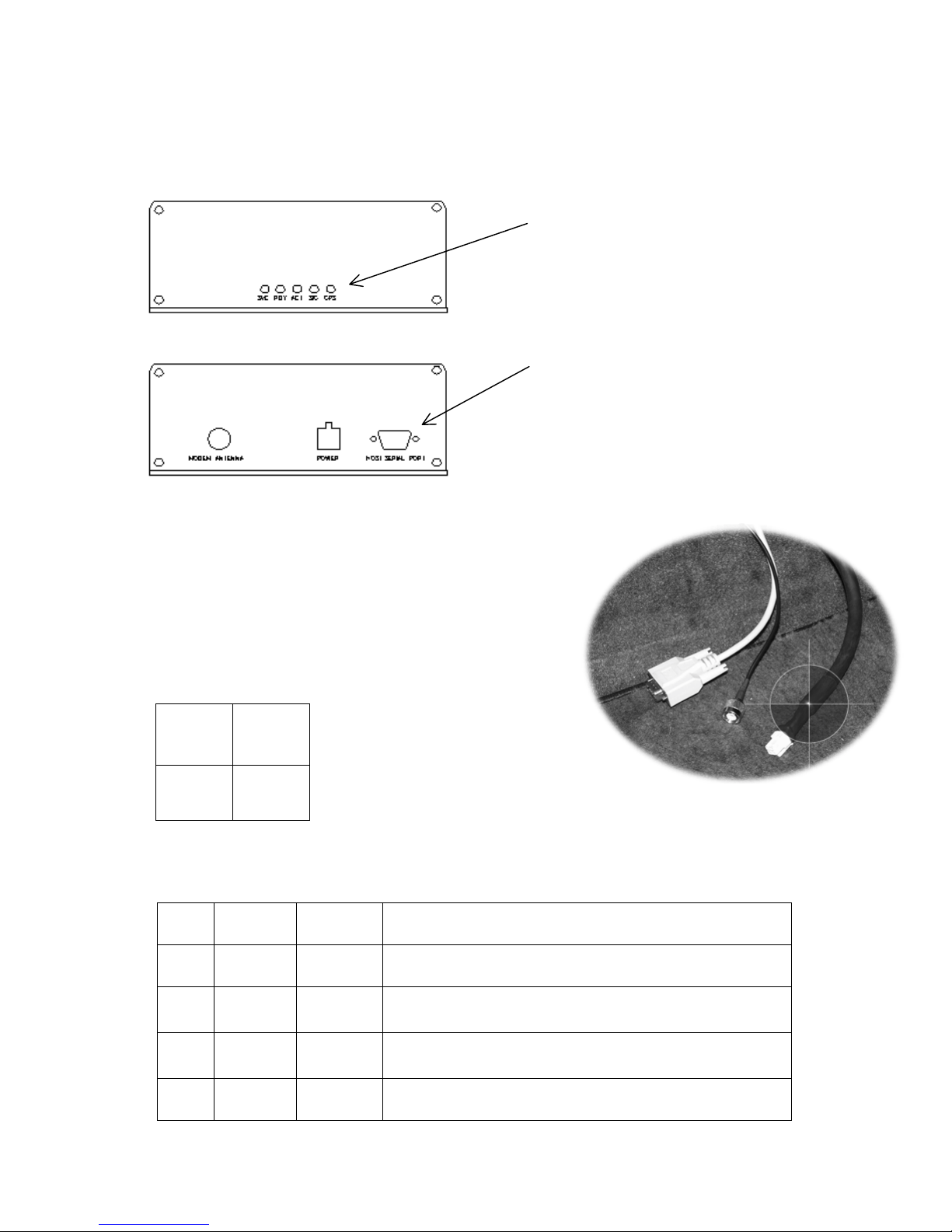
The modem front and rear panels ar e shown in the figures below.
These LEDs (or signal indicators)
show the modem operating status.
See section 2.2 LED Indicators on
page 2-2 for details.
Front panel
Rear panel
Figure 1. Modem LEDs and Connections
2.1 Power Connector
The power connector for the Lancer 3W is a Molex
connector that mates with Molex connectors
(39-01-2040 or 39-01-2045). The pinout (looking
into the modem) is shown below.
1
Alert
2
Ignition
These connectors are for use in
connecting cables. See section
3.5.3 Connecting The Cables on
page 3-6 for details.
3
GND
4
PWR
The following table lists power-pin colors and describes their function:
Table 1. Power Connector Pin Descriptions
Pin Color Function Description
1 White Alert Can be connected to horn to provide an alert signal.
2 Green Ignition Keeps modem operational for a user defined time
3 Black Gnd Common Vehicle Ground (negative battery terminal)
4 Red Power
Power Cable Connector
period after the key is removed from the ignition switch.
Vehicle power lead (positive battery terminal)
2-1

Lancer 3W Installation Guide
2.2 LED Indicators
The modem has five LED indicators on its front panel as shown in Figure 1. The f ollowing
table explains functions of each LED:
Table 2. LED Indicators
LED Function Description
SVC
RDY
ACT
Service
Ready
RF Activity This LED is on when the modem attempts to send or retrieve a data
• Blinking at a slow rate indicates that the modem is actively
searching for a CDPD Channel.
• Blinking at a fast rate indicates that the modem is attempting to
register on a CDPD Channel.
• Steady on indicates that the modem is registered on the CDPD
network.
• Steady off indicates either; -
• No power is being applied to unit.
• The modem is not configured to register.
• Steady on indicates that the modem is registered on the CDPD
network, locked on to a channel and capable of sending and
receiving data.
• Steady off indicates one of the following:
• Lack of power.
• The modem is not configured to register.
• The modem is not locked to a CDPD channel.
• The modem is out of coverage.
packet. To receive a data packet, the packet IP must be valid for
reception. A packet discarded by IP screening or friends mode will
not activate this indicator.
SIG
GPS
Signal Quality This LED shows the quality of a signal as follows:
• Blinking at a slow rate indicates a poor signal (RSSI of less
than -100 dBm).
• Blinking at a fast rate indicates a moderate signal (RSSI of less
than -80 dBm).
• If the BLER is higher than 3% then the quality level will be
reduced to the next lower indication.
• Steady on indicates that signal is good, RSSI is above -80 dBm.
• Steady off indicates no signal present.
GPS Lock This LED shows one of the following conditions:
• Steady on indicates that the GPS module has locked on to one
or more satellites.
• Steady off indicates that the GPS unit is not installed, not active
or cannot lock on to at least one satellite.
2-2
 Loading...