

Page 1

WinFrog Device Group: GPS
Device Name/Model: NOVATEL CON (CONSOLE)
NOVATEL INC.
1120 - 68th Avenue N.E.
Device Manufacturer:
Calgary, Alberta, Canada, T2E 8S5
Tel: U.S. & Canada: 1-800-NovAtel
Fax: (403) 295-4501
E-mail: gps@NovAtel.ca
Device Data String(s)
Output to WinFrog:
WINFROG DATA STRING(S)
Output to Device:
WinFrog Data Item(s) and their
RAW record:
Refer to Configuration Details Section
Configuration/Control Telegrams
RTCM (if turned on at Device Level)
POSITION 303
DEVICE DESCRIPTION:
The NovAtel GPSCard
TM
PC Series products are GPS receivers that are configured as
PC cards rather than as stand alone devices, allowing for the unit to be installed
internally in a host desktop computer. Instead of relying on a serial connection (and the
required cabling) to communicate with the computer, GPSCards utilize the PC ISA bus.
GPSCards are also configured with dual RS232 ports allowing for input and output of
data via serial connections, if so desired. These 2 DB9 male connectors allow you to
receive differential corrections from a DGPS receiver or output data to another
computer, with baud rates varying from 300 to 115,200 bps.
The GPSCard
TM
PC Series are 12 channel parallel tracking, C/A code GPS receivers,
utilizing the L1 (1575.42 MHz) frequency GPS signal. The NovAtel custom proprietary
correlater chip, combined with a high performance 20 MHz 32-bit CPU is capable of
measuring satellite code and carrier phase data to compute up to 10 position solutions
per second. Positional data (stand alone or differentially corrected) can be output at a
rate of up to 20 times per second.
For use with WinFrog, these cards are set to output raw Pseudorange and Ephemeris
data as well as internally calculated, differentially corrected positions. WinFrog’s
optional GPS Calculations extension module can combine the raw Pseudorange and
Ephemeris data with up to 5 differential GPS corrections to provide a Multi-Ref position
(See chapter 14 of the WinFrog Users Guide for more details).
The internally calculated position can utilize differential corrections received via the
serial ports or the PC ISA bus.
The GPSCards must be correctly installed and configured before they can be used with
WinFrog. This involves that you follow specific installation procedure, not just simply
installing the card into the computer. These instructions are listed below in the section
entitled Driver Installation.
This device can provide time synchronization using $--ZDA. See chapter 8.
WinFrog User’s Guide - Appendix C – GPS/NovAtel Con Page 1 of 22
Page 2
DEVICE CONFIGURATION INSTRUCTIONS
WINFROG I/O DEVICES > EDIT I/O:
The NovAtel CON (console) device is added to WinFrog from the GPS device group.
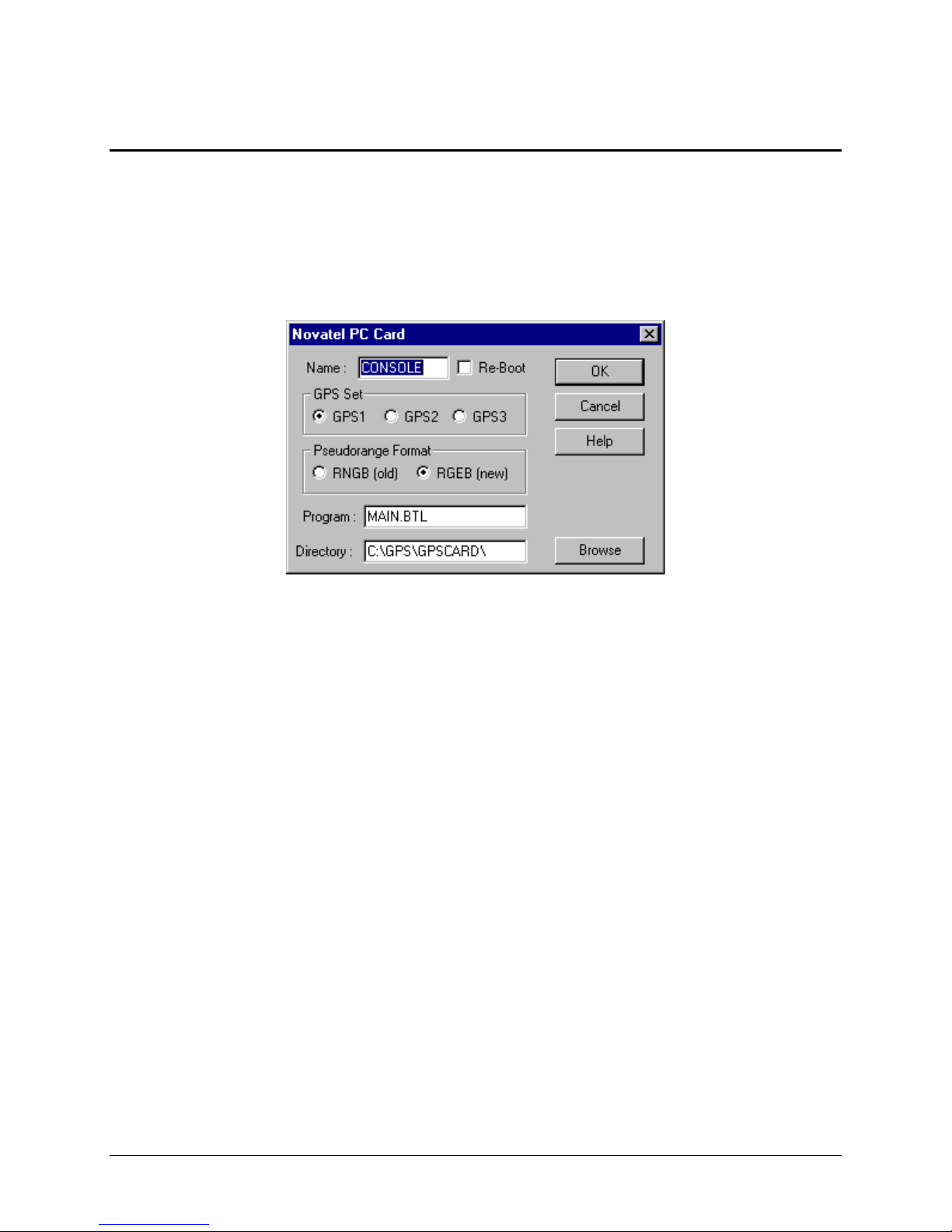
The Novatel PC Card dialog box (shown below) appears when the NovAtel CON
(console) device is selected. Within this dialog are various configuration options. The
settings are dependant on the GPSCard that has been installed in the PC.
Name: Enter the name of this GPSCard, or leave the default.
Re-Boot: Enable this option to re-start the GPSCard if it has been shutdown. The re-
boot will take place once you click OK to close this dialog box.
GPS Set: This section allows you to select which GPSCard to use. As detailed below,
you can add up to 3 GPSCards to a single PC. Each card is identified uniquely as
GPS1, GPS2 or GPS3. Select the appropriate radio button (usually GPS1).
Pseudorange Format: Most cards use the default RGEB (new) format.
Program: This window must display the correct .btl file name, as defined by the
GPSCard serial number. Note that all of the .btl files that were updated for the year
2000 week rollover should have the prefix Y2K.
Directory: Type in the appropriate folder name/location, or select the Browse button to
navigate to the appropriate directory where the .btl file is found. When you click Ok to
close this window, the GPS card is “booted” (i.e. started). A message will appear if there
is a problem with booting the card. A common error is experienced when WinFrog tries
to boot the GPSCard while it is already running. The card can be started when the
drivers are installed, and shutting down the card is often overlooked. To manually shut
down the card, go to Window’s Start > Settings > Control Panel > Devices. Highlight the
GPSCard device and select Stop.
WinFrog User’s Guide - Appendix C – GPS/NovAtel Con Page 2 of 22
Page 3
If problems persist, refer to the Configuration Details section below for information on
setting up the GPSCard and installing the required files.
WINFROG I/O DEVICES > CONFIGURE DEVICE:
This device must be configured at the I/O Device window level. In the I/O Devices
window, click the device name to select it, then right-click and select Configure Device.
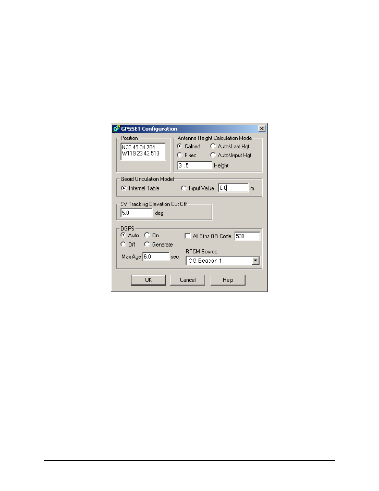
The GPSSET Configuration dialog box appears, as seen below. This configuration
dialog sets the internal calculation parameters of the NovAtel GPSCard.
Position:
An approximate initial position must be entered to provide the position calculations
with a reasonable starting point. This position should be within approximately 5
minutes in both Latitude and Longitude. Ensure that the “quadrant” signifiers are
correct: N/S or E/W.
Antenna Height:
Set the antenna height mode to one of the two provided options:
Calculated – Along with Latitude and Longitude, the NovAtel GPSCard will
calculate the GPS antenna Geoidal Height (Mean Sea Level). A minimum of four
satellites must be tracked in order to calculate both horizontal position and
height.
Fixed - Fixes the GPS antenna height to the Geoidal Height (Mean Sea Level)
value entered in the
provided entry box. In this mode, the NovAtel GPScard is
able to calculate horizontal positions using a minimum of three satellites.
WinFrog User’s Guide - Appendix C – GPS/NovAtel Con Page 3 of 22
Page 4

Auto\Last Height & Auto\Input Height – No Auto Height options are used by
the GPScard.
Note: Heights entered in the provided entry box must refer to the geoid (Mean
Sea level). In some other WinFrog dialog boxes, heights are displayed with
respect to the vehicle’s selected zero vertical reference point.
Undulation Model:
The Undulation Model can be set to the Internal Table, which uses the NovAtel’s
internal (OSU) geoid model, or Input Value in which case a specific Ellipsoid
separation value can be input. This Ellipsoid separation value is used to calculate
Ellipsoid height from the entered geoidal (Mean Sea Level) elevation, using the
following formula:
h = H + N Where: h = Ellipsoid height (of the antenna)
H = MSL (ie geoid) height (of the antenna)
N = Geoid height (undulation)
Unless you have accurate ellipsoid/geoid separation values from another source,
select the Internal Table radio button.
SV Tracking Elevation Cut Off:
Enter a mask angle value, in degrees. The GPSCard will not use measurements
from any satellites with elevation angles below the angular value input in the
Elevation (angle) Cut Off entry box.
DGPS:
This section of the dialog allows you to set the mode by which the GPSCard will
internally apply received differential GPS corrections.
There are four different DGPS modes: Auto, On, Off and Generate.
Auto: The GPSCard will automatically use differential corrections in its position
calculations, when available. If no corrections are available, the GPSCard will
compute a single point (aka autonomous) position solution.
On: The GPSCard will always attempt to use differential corrections. If no
corrections are available, no position will be computed.
Off: The GPSCard will not use differential corrections in its position
computations, even if they are available. Instead it will always compute a single
point GPS solution.
Generate: The GPSCard will generate differential corrections based on a fixed
reference position. This option is used for Base Stations only.
WinFrog User’s Guide - Appendix C – GPS/NovAtel Con Page 4 of 22
Page 5

Maximum Age (of Corrections): If the GPS mode is set to Auto or On, the
GPSCard will only apply the corrections if the received RTCM data is less than
the specified Max. Age (entered in seconds).
Code: This allows you to define which DGPS reference station will be used, as
defined by its Code. If you don’t know the code of the station being received,
select All, in which case the GPSCard will use any received RTCM data.
RTCM Source: Use the dropdown list to select which RTCM receiving device will
be used to provide the GPSCard with differential corrections. This RTCM
receiver must be interfaced to WinFrog before it will be listed. The RTCM data is
received via a serial connection, and is passed to the GPSCard via the ISA bus.
WINFROG VEHICLE > CONFIGURE VEHICLE DEVICES > DEVICE DATA ITEM >
EDIT:
Adding a NovAtel CONSOLE device to WinFrog provides you with three separate data
items: Position, Pseudorange and Ephemeris. The GPS, CONSOLE, POSITION data
item refers to the position data calculated and output by the GPSCard. The GPS,
CONSOLE, PSEUDORANGE and GPS, CONSOLE, EPHEMERIS data items provide
WinFrog with only raw measurement data. WinFrog’s GPS Calculations extension
module is required to combine these measurements to calculate a position.
WinFrog can use either or both position solutions. Adding the Position data item is
simpler but provides the vehicle with only a single GPS or DGPS position. Using the
Pseudorange/Ephemeris option provides the ability to set up a multiple reference
solution - you can add DGPS correction data from up to 5 different RTCM stations,
which are then combined resulting in 1 weighted mean solution.
No matter which positioning method is selected, you must edit the device to suit the
application, as detailed below. (Note that the Ephemeris data item requires no editing).
GPS, CONSOLE, POSITION
In the appropriate vehicle’s Configure Vehicle - Devices dialog box, highlight the
POSITION data item and click the Edit button. The Configure Position dialog box
appears as seen below:
WinFrog User’s Guide - Appendix C – GPS/NovAtel Con Page 5 of 22
Page 6
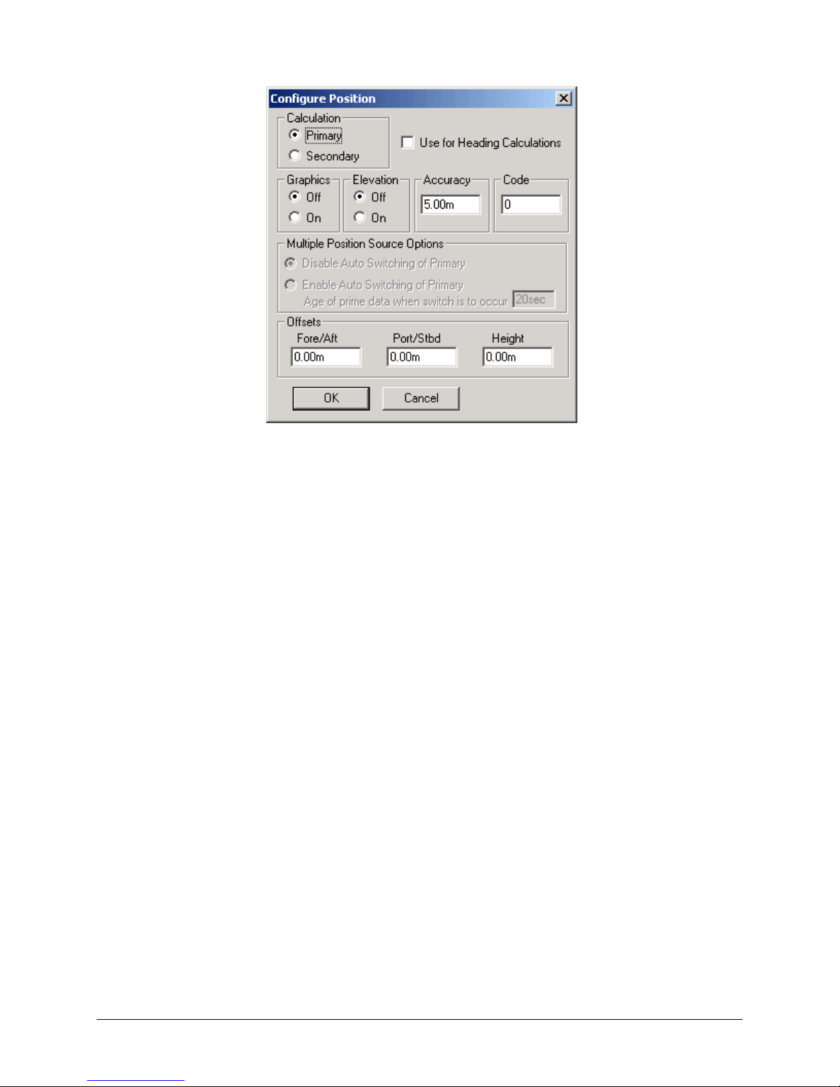
The following items are available for configuration:
Calculation:
Set the Calculation selection to Primary or Secondary. Devices set to Primary
calculation are used to provide a vessel position. Note that more than one Primary
positioning device can be added to a vehicle’s device list; data from these devices
will be combined in a weighted mean solution. (See the paragraph on Accuracy
below for more on the weighting of Primary calculation device data).
If the Calculation type is set to Secondary, WinFrog will simply monitor the device’s
data. WinFrog will not use the data from a secondary device in the final solution of
the vehicle’s position.
If auto switching is enabled (see below) a secondary may automatically become a
primary should all the primaries fail.
Use For Heading Calculations:
Select this checkbox if this GPS position is to be used in conjunction with another
GPS device for determination of the heading of the vessel. The vessel’s heading will
be derived by the inverse of the GPS antenna coordinates.
Graphics:
If On is selected, a labeled square will be made visible in the Graphics and Bird’s
Eye displays, depicting the raw (unfiltered) location of the GPS antenna. This
provides a means of comparing raw and filtered positions between different sources.
WinFrog User’s Guide - Appendix C – GPS/NovAtel Con Page 6 of 22
Page 7

Elevation:
If On is selected, the elevation determined by the GPS will be used as the elevation
of the antenna with respect to the WGS84 Ellipsoid. Do not enable this option unless
you are utilizing high accuracy (centimeter level) RTK type GPS positioning.
Accuracy:
The Accuracy value is the expected accuracy (i.e. standard deviation) of the
positioning device. This value is used in the weighting of this device relative to other
primary positioning devices, and in the vehicle’s kalman filtering. The default values
should be changed only if you have confidence that newly entered accuracy values
are more correct than the default values.
You must also be cautious of setting both a Multi-Ref position and a single source
DGPS position as primary positioning devices. This will weight the single position
equal to the 5 positions combined to create the Multi-Ref position.
Code:
Set the Code to coincide with the code parameters that may be associated with the
GPS unit being used, as required when using telemetered GPS data. This is usually
set to 0.
Multiple Position Source Options:
This group box allows you to enable automatic switching of a secondary to primary
should the data from all POSITION and PSEUDORANGE data items set to primary
timeout. The Age entered is the length of time that the secondary will wait in the
absence of data from all primaries, before taking over as primary. This age is only
entered for the secondary.
For example, if the POSITION or PSEUDORANGE data items associated with two
GPS receivers were set to primary and the POSITION or PSEUDORANGE data
item of a third GPS receiver was set to secondary, both primary GPS receivers must
time out before the secondary will become the primary. Upon the recovery of either
of the original primary data items, the original primary will be reset to primary and the
original secondary will be reset to secondary.
Note for the auto switching feature to work, there must be at least one primary and
one secondary enabled. For example, given two data items, one set to primary with
the auto switching disabled and the other set to secondary with the auto switching
enabled, if the primary fails the secondary is not set to primary and the vehicle
positioning stops until the primary data item recovers.
Disable Auto Switching of Primary:
If this data item is not to be involved in the auto switching process, check this
box. As stated above, this data item is then not involved in the auto switching
process in any way.
WinFrog User’s Guide - Appendix C – GPS/NovAtel Con Page 7 of 22
Page 8

Enable Auto Switching of Primary:
If this data item is to be involved in the auto switching process, either as a
primary or a secondary, check this box. If set to secondary, enter the Age of data
the primary data items must reach before this secondary is switched to act as the
primary.
In order for this option to be effective you must have at least one primary and one
secondary. If there are multiple secondary data items that are enabled for switching,
the first one to receive data will become primary.
Note: This option is not enabled unless WinFrog determines that there is more than
one POSITION and/or PSEUDORANGE data item associated with the respective
vehicle. The exception to this is the case of a WinFrog with the Remote module
operating as a Controlled Remote being configured remotely from the Controller. In
this case, the option is always enabled even though it may not be applicable. The
operator must be aware of what is available on the Remote and configure the data
item accordingly.
Note: This option is not available in the WinFrog Remote package.
Note: This option is not available for USBL based POSITION data items.
Offsets:
Offsets are entered to relate the GPS antenna position to the vessel’s Common
Reference Point (aka CRP). Offsets are entered as measured from the CRP (of the
vehicle) to the device (antenna) location. Offsets Fore and Starboard are entered as
positive values, Offsets measured Port and Aft are entered as negative values.
Rule of thumb suggests the CRP “Z” reference should be at the water line.
GPS, CONSOLE, PSEUDORANGE
The PSEUDORANGE data item must be edited once it is added to a vehicle’s device
list. Highlight the data item in the vehicle’s device list and click the Edit button. The
Pseudorange Calculation dialog box appears as seen below.
WinFrog User’s Guide - Appendix C – GPS/NovAtel Con Page 8 of 22
Page 9

Calculation:
Set the Calculation selection to Primary or Secondary. Devices set to Primary
calculation are used to provide a vessel position. Note that more than one Primary
positioning device can be added to a vehicle’s device list; data from these devices
will be combined in a weighted mean solution. (See the paragraph on Accuracy
below for more on the weighting of Primary calculation device data).
If the Calculation type is set to Secondary, WinFrog will simply monitor the device’s
data. WinFrog will not use the data from a secondary device in the final solution of
the vehicle’s position.
If auto switching is enabled (see below) a secondary may automatically become a
primary should all the primaries fail.
Accuracy:
The Accuracy value entered provides WinFrog with the expected accuracy of the
position from this device. This value is used in the weighting of this device compared
to other positioning devices that may be added to the vehicle’s device list. The
smaller the value entered, the more accurate it is considered to be, and hence the
more weight that will be applied to the device’s data. The Accuracy parameter can
be changed from the suggested values, although changes should be made with
caution, as they will affect the final filtered position of the vehicle.
WinFrog User’s Guide - Appendix C – GPS/NovAtel Con Page 9 of 22
Page 10

The Velocity value is used in positional filtering. The lower the value entered, the
more smoothing that is applied.
Remote Unit ID:
The Remote Station ID parameter is set to zero (0) unless the GPS device is
interfaced to WinFrog via a telemetry device.
Multiple Position Source Options:
This group box allows you to enable automatic switching of a secondary to primary
should the data from all POSITION and PSEUDORANGE data items set to primary
timeout. The Age entered is the length of time that the secondary will wait in the
absence of data from all primaries, before taking over as primary. This age is only
entered for the secondary.
For example, if the POSITION or PSEUDORANGE data items associated with two
GPS receivers were set to primary and the POSITION or PSEUDORANGE data
item of a third GPS receiver was set to secondary, both primary GPS receivers must
time out before the secondary will become the primary. Upon the recovery of either
of the original primary data items, the original primary will be reset to primary and the
original secondary will be reset to secondary.
Note for the auto switching feature to work, there must be at least one primary and
one secondary enabled. For example, given two data items, one set to primary with
the auto switching disabled and the other set to secondary with the auto switching
enabled, if the primary fails the secondary is not set to primary and the vehicle
positioning stops until the primary data item recovers.
Disable Auto Switching of Primary:
If this data item is not to be involved in the auto switching process, check this
box. As stated above, this data item is then not involved in the auto switching
process in any way.
Enable Auto Switching of Primary:
If this data item is to be involved in the auto switching process, either as a
primary or a secondary, check this box. If set to secondary, enter the Age of data
the primary data items must reach before this secondary is switched to act as the
primary.
In order for this option to be effective you must have at least one primary and one
secondary. If there are multiple secondary data items that are enabled for switching,
the first one to receive data will become primary.
Note: This option is not enabled unless WinFrog determines that there is more than
one POSITION and/or PSEUDORANGE data item associated with the respective
vehicle. The exception to this is the case of a WinFrog with the Remote module
operating as a Controlled Remote being configured remotely from the Controller. In
this case, the option is always enabled even though it may not be applicable. The
WinFrog User’s Guide - Appendix C – GPS/NovAtel Con Page 10 of 22
Page 11

operator must be aware of what is available on the Remote and configure the data
item accordingly.
Note: This option is not available in the WinFrog Remote package.
Antenna Height:
Set the Antenna Height using the radio buttons and the (input) Ellipsoid Height field.
Settings are as follows:
Calculated – Select this option to force WinFrog to calculate the GPS antenna
Height, as well as its Latitude and Longitude. In this mode, WinFrog requires a
minimum of four satellites to be visible.
Fixed – Select this option to fix the GPS antenna ellipsoid height to the value
entered in the
Ellipsoid Height field. In this mode, WinFrog is able to calculate
valid positions using a minimum of three satellites.
Auto\Last Height – If this mode is selected, WinFrog will calculate a 3D position
if four or more satellites are available. If only three satellites are visible, or if the
VDOP of the solution exceeds the value set in the Alarms dialog box,
the height
is fixed to that of the last valid position. In this mode WinFrog is able to calculate
valid positions using a minimum of three satellites.
Auto\Input Height – If this mode is selected, WinFrog will calculate a valid 3D
position if four or more satellites are available. If only three satellites are
available, or if the VDOP of the solution exceeds the value set in the Alarms
dialog box, the height is fixed to the value entered in the
Ellipsoid Height field.
In this mode, WinFrog is able to calculate valid positions using a minimum of
three satellites.
Note: The Antenna height entered in the Pseudorange Calculation dialog box
refers to the WGS 84 Ellipsoid.
Offsets:
Offsets are entered to relate the GPS antenna position to the vessel’s Common
Reference Point (CRP). Offsets are entered as measured from the CRP (of the
vehicle) to the device (antenna) location. Offsets Fore and Starboard are entered as
positive values, offsets measured Port and Aft are entered as negative values. Rule
of thumb suggests the CRP “Z” reference should be at the water line.
DGPS Mode:
Select the desired mode of DGPS operation
There are four different DGPS modes: Auto, On, Off and Generate.
Auto: WinFrog will automatically use differential corrections in its position
calculations, when available. If no corrections are available, WinFrog will
compute a single point (autonomous) position solution.
WinFrog User’s Guide - Appendix C – GPS/NovAtel Con Page 11 of 22
Page 12

On: WinFrog will always attempt to use differential corrections. If no corrections
are available, no position will be computed.
Off: WinFrog will not use differential corrections in its position computations,
even if they are available. Instead it will always compute a single point GPS
solution.
Generate: WinFrog will generate differential corrections based on a fixed
reference position. This option is used for Base Stations only.
Phase Smoothing:
Phase smoothing utilizes the GPS receiver’s observations of the GPS satellite’s
carrier signals. Because the GPS L1 frequency has a wavelength of only 19 cm.,
measurements made using this signal will provide higher accuracy than
measurements made on the C/A code message modulated onto the L1 signal. Note,
however, that since the carrier phase position is derived from the C/A code position,
it does not offer an improvement in precision.
If the Phase Smoothing feature is enabled, WinFrog will use the C/A Code derived
(DGPS corrected) position to derive the number of L1 wavelengths to each of the
observed satellites. Over the length of time entered into the Filter Length field
(value in seconds), WinFrog will switch the GPS calculated position from the C/A
code position to the derived Carrier Phase position.
WinFrog will continue to use the carrier phase data to provide positioning until the
Cycle Slip Tolerance is exceeded. A Cycle Slip is the loss of lock on a satellite’s
signal. This loss of lock forces WinFrog to re-establish the number of wavelengths
from the antenna to the satellite. If the number of cycle slips exceeds the Cycle Slip
Tolerance, WinFrog will resort back to the C/A code position and re-calculate the
number of wavelengths to all received satellites.
Graphics:
Select the On radio button to display a labeled square in the Graphics and Bird’s
Eye displays depicting the raw (unfiltered) location of the GPS antenna. This
provides a means of comparing raw and filtered positions between different sources.
Display:
The selection made here determines which type of information will be displayed in
WinFrog’s Calculations window (when the GPS Pseudorange device is turned on for
display in that window). Select from the three provided options:
Results – The Calculations window will show the results of the GPS
Calculations, including the Multi-Ref position and all individual solutions.
Data - The Calculations window will show the results of the GPS Calculations,
including the Multi-Ref position and data related to each individual carrier phase
solution (when Phase Smoothing is enabled).
WinFrog User’s Guide - Appendix C – GPS/NovAtel Con Page 12 of 22
Page 13

Statistics - The Calculations window will show the results of the GPS
Calculations, including the Multi-Ref position and statistical data related to each
individual solution.
Use For Heading Calculations:
Select this checkbox if the device is to be used in conjunction with another GPS
device for determination of heading of the vessel. In most cases, only high accuracy
receivers should be used for heading calculations as WinFrog simply inverses the
individual sensors’ raw positions to derive the bearing between them.
Use Elevation:
Setting the Elevation option to “On” will result in the elevation determined by GPS to
be used as the elevation of the vessel’s CRP referencing the GPS (WGS84)
Ellipsoid. The height of the antenna above (below) the CRP must be entered. Do not
enable this option unless you are utilizing high accuracy (centimeter level) RTK type
GPS positioning.
Alarms:
Click this button to view and enable various GPS alarms, as described below.
GDOP – Geometric Dilution of Precision. GDOP is a numerical value that serves
as a measure of the effect of the satellite constellation’s geometry on the derived
positional accuracy. In other words, the GPS receiver’s measurement accuracy is
multiplied by the GDOP value to derive the overall positional accuracy of the
GPS receiver (including the three positional dimensions and clock offset). If the
GDOP mask is set to On and the calculated GDOP exceeds the entered value,
WinFrog will not compute a position solution using pseudoranges. If the
Calculations window is enabled, an alarm will sound to indicate that the GDOP
has been exceeded.
VDOP – Vertical Dilution of Precision. This parameter is also calculated from
satellite geometry and gives an indication of the expected accuracy of the vertical
component of the GPS position solution. If the VDOP mask is set to On and the
WinFrog User’s Guide - Appendix C – GPS/NovAtel Con Page 13 of 22
Page 14

calculated VDOP exceeds the entered value, WinFrog will automatically initiate
2D or fixed height mode using either the last valid calculated height or the height
entered in the Antenna Height Ellipsoid Height field. If the Calculations window
is enabled, an alarm will sound to indicate that the VDOP has been exceeded.
Elev. Cutoff – (Elevation Angle Cutoff). WinFrog will not use measurements from
any satellites with elevation angles below the angular value input in the Elevation
Angle Cutoff field. Any satellites not used in the pseudorange position
calculations are indicated in the
Calculations window by a change of color.
Min SN – Minimum Signal to Noise. This field is used to set the minimum signal
to noise ratio for the pseudorange calculations. If a satellite’s signal to noise ratio
falls below the entered value, the satellite will not be used in position computation
by WinFrog. Satellites not used in the position computation due to low signal to
noise values are indicated in the Calculations window by a change of color.
Max Res – Maximum Measurement Residual. WinFrog will not use any satellite
measurement with a residual greater than the Maximum Measurement Residual
in its pseudorange position computations. Satellites not used in the position
computation due to measurement residuals are indicated in the Calculations
window by a change of color.
Max RTCM Age – Maximum RTCM Differential Correction Age. This parameter
sets the maximum latency of real time differential corrections for pseudoranges.
If the maximum latency is exceeded, WinFrog will not apply the corrections from
that RTCM source. To indicate this condition, the
STAT light in the Position
portion of the Calculations window will turn yellow. Click on the ACK button to
acknowledge this alarm.
Tests:
Click this button to open the GPS Solution Statistical Testing dialog box, as seen
below.
This dialog box provides you with the ability to enable or disable statistical w test
and F tests. By default, both of the w-test and the F-test are turned off.
WinFrog User’s Guide - Appendix C – GPS/NovAtel Con Page 14 of 22
Page 15

w-Test:
The w-test entails normalizing the residuals of a GPS pseudorange solution and
testing these against a 99% confidence limit for outliers. This limit is 2.576. If
outliers are found, they are removed and the solution is re-executed excluding
that satellite data pertaining to the outlier. If more than one satellite is found to
produce a residual outlier, only that satellite with the largest normalized residual
is eliminated. This continues until no outliers are present or until the exclusion of
any more data would result in insufficient data for a solution (four satellites for 3D
and three for 2D). Since the normalized residuals tend towards being equal with
reduced redundancy (as the number of satellites used in the solution approaches
the minimum required), it is unlikely that WinFrog will ever have to stop the
exclusion of data due to insufficient satellites. Nonetheless, WinFrog still checks
for this condition.
Caution should be exercised when using this option. If the vessel is too far away
from the selected reference stations and/or there are few satellites in common
with the vessel and the reference station(s) the w-test option may eliminate data
to the point where the solution approaches the minimum required.
F-Test:
The F-test is a check of the unit variance of the GPS pseudorange solution. This
confirms the validity of the model used for the solution and the weighting of the
observations used. Note that it is only a confirmation check, no data or solution
results are thrown out based on the results of the test.
The unit variance is the sum of the weighted, squared residuals, divided by the
degrees of freedom (number of redundant measurements) in the solution. The FTest should result in unity. If the unit variance is consistently different from unity,
it indicates that there may be a problem with the stochastic model used, or an
unmodeled bias in the data.
RefStns:
Click the RefStns button in the Pseudorange Calculation dialog box to open the
Select DGPS Reference Stations dialog box, as seen below.
WinFrog User’s Guide - Appendix C – GPS/NovAtel Con Page 15 of 22
Page 16

The Select DGPS Reference Stations dialog box allows you to define which
reference stations will be used by WinFrog in its Multi-Ref solution. You can
either configure WinFrog to simply use all received stations (to a maximum of 5),
or you can control the use of corrections, as deemed proper.
To use all received DGPS corrections, select the Use all Available Stations
checkbox. When this checkbox is selected, all available RTCM corrections are
utilized in the solution, each with the same Relative Standard Deviation.
The individual station method is preferable as it allows you to remove or deweight solutions that may not agree with the weighted mean solution. If this
method is used, you should add the RTCM data item to the vehicle’s device list
once for each solution, then edit that solution entering the proper code and
coordinates. For example, if there are five Reference stations to be used in the
Multi-Ref solution, add the RTCM,RTCM1,DGPS-COR’s data item to the
vehicle’s device list five times.
From the Configure Vehicle-Devices dialog box, highlight and edit each RTCM
data item to indicate a unique Code.
Now, back in the Select DGPS Reference Station dialog box, ensure that the
Use all Available Stations checkbox is not selected. Now the individual reference
station ID’s must be entered, along with station usage and relative standard
deviation values, as detailed below:
Select DGPS Reference Stations:
Selection of individual stations is as follows:
WinFrog User’s Guide - Appendix C – GPS/NovAtel Con Page 16 of 22
Page 17

ID – The Reference Station identification code. See SkyFix documentation for a
listing of all SkyFix reference station ID Codes. Coast Guard Beacon corrections
also contain unique codes for each station.
In the above example, SkyFix stations 535, 545 and 570 are used with assigned
relative standard deviations along with Coast Guard station 336. Coast Guard
Station 334 is monitored and is therefore not utilized in the position solution.
Off – Corrections from the selected Reference Station will not be used in the
Multi-Ref position solution. This individual solution and will appear in red text in
WinFrog’s Calculations window and not update.
Use – Reference Station is used in the Multi-Ref position solution, and will
appear in the Calculations window in black text. This individual solution will
appear in red text if no solution (refer to DGPS Mode) can be calculated from the
data.
Monitor – Reference Station is simply monitored by WinFrog, and is not used in
the Multi-Ref position. This solution will appear in yellow text in WinFrog’s
Calculations window.
Rel. Std. Dev – This value defines the relative standard deviation of this solution
as compared to the other solutions used in the Multi-Ref position. Equal Rel. Std.
Dev. values indicate that all individual solutions will be equally weighted in the
Multi-Ref solution. Entering a higher Rel. Std. Dev value will de-weight an
individual solution compared to the others in the Multi-Ref solution.
CONFIGURE CALCULATIONS WINDOW
A Calculations window can be configured in WinFrog, allowing you to monitor the status
of the Mulit-Ref solution and make appropriate adjustments. To open the Calculations
window select View > Calculations from the main menu. In the Calculations window,
select the appropriate vehicle from the dropdown list and click the Setup button.
In the Setup Calculation Views dialog box, select the Position and Data Item Text
checkboxes. Next, highlight the Pseudorange data item, click the On button and exit
with OK. Refer to Chapter 14, GPS Calculations Displays section of the WinFrog User’s
Guide for more detailed descriptions of the various options and displays available with
the Calculations window.
WinFrog User’s Guide - Appendix C – GPS/NovAtel Con Page 17 of 22
Page 18

CONFIGURATION DETAILS:
Before you install the card, you must ensure that the Address and IRQ settings are
correct, and that they do not conflict with other hardware installed on the same PC.
The GPSCard’s default DIPswitch settings configure the card with a base address of
150 and an IRQ (interrupt request) setting of 5. (Switch 2 in the on position represents
an address of 150, and switch 4 on position represents an IRQ of 5 as shown below).
For more information on the different IRQ and Address settings, please refer to the
NovAtel manual.
NovAtel Card: Base Address and IRQ DIP Switch Setting
WinFrog User’s Guide - Appendix C – GPS/NovAtel Con Page 18 of 22
Page 19

Device Data String(s)
Output to WinFrog:
Upon bootup, WinFrog sends the GPSCard command messages to initiate the output of
the following data:
REPB: raw ephemeris data
RCCA: receiver configuration
ALMB: almanac, ion & utc data
SATB: satellite specific data
RGEB: channel measurements new format
RNGB: channel measurements old format
CTSB: channel-tracking status
GPGGA: GGA position message
P20B: RT20 P20 position message
GPGSA: GSA message
GPGST: GGA message
GPZDA: ZDA message
SVCB: SV x,y,z,ion,trop,clk
Note: The NovAtel Console uses binary messages (as opposed to ASCII). This is
defined in the last letter of the above codes, i.e ALMB is a binary message, while ALMA
is an ASCII message.
WinFrog User’s Guide - Appendix C – GPS/NovAtel Con Page 19 of 22
Page 20

Driver Installation:
In addition to correctly configuring the GPSCard’s address and IRQ settings, you must
also install the correct firmware to run the GPSCard.
In order to install the driver you must first locate the appropriate boot file for the specific
card that you are using. This boot file (named main.btl) is sent along with the GPSCard
when delivered from the factory. Although all NovAtel boot files are named main.btl,
each file is tagged to a specific GPSCard and cannot be interchanged with other
software or GPSCards. It is standard practice at Fugro Pelagos to rename the main.btl
file to match the GPSCard’s serial number, as found on the circuit board (retaining the
.btl file extension). Also, if you are using an older NovAtel GPS Card (pre-2000), you
must ensure that the boot file used is year 2000 (Y2K) compliant.
To install the driver:
1. Using NT Explorer, click on File and create a directory called GPS.
2. Insert the boot file disk into drive A. Copy the boot file that corresponds to the
serial number of the GPS card (for example 090240.btl), to the GPS directory.
3. Insert the disk that has the NTDLL sub-directory into Drive A and then copy the
NTDLL subdirectory into the GPS directory. From the C:\GPS directory copy the
following files ntgpsdrv.sys and pcgps3nt.dll into the following directories
c:\winnt\system32\drivers and c:\winnt\system32 respectively.
4. Exit NT Explorer. Start MSDOS Prompt. Use the cd command to change to the
C:\GPS\NTDLL directory. (i.e. type cd C:\GPS\NTDLL <enter>)
5. Type the following line then press <enter>.
gpsinst /Dc:\winnt\system32\drivers\ntgpsdrv.sys /NGPS1 /I5 /A150
6. To check that the driver is correctly installed, type “gpsquery” and press
<Enter>. The driver parameters will show indicating that it has been successfully
installed.
7. You must now load the boot file by typing the following line and pressing <Enter>.
gpsload /NGPS1 c:\gps\the bootable file (such as 090240.btl) <enter>
8. At this point, the red light on the card should be flashing, indicating that the card
has been booted correctly.
9. Type gpscon /NGPS1 <enter>. Gpscon enables you to issue commands directly
to the GPSCard via the PC keyboard.
10. Type log console rcsa <enter>. This command allows you to monitor the
receiver status. The rcsa will display the Version, Channels, Idle and Status of
the receiver. By looking at the status code you will be able to determine whether
WinFrog User’s Guide - Appendix C – GPS/NovAtel Con Page 20 of 22
Page 21

there is an error with the GPS card or not. For example: Code 00000xF7
indicates that the GPS antenna and GPS Card are correctly installed and
functioning properly. Code 00000xF6 indicates an antenna fault while the GPS
Card status is good.
11 To exit, press <Esc>. Type <Exit> in order to exit the DOS Prompt and return to
Program Manager.
Installation of two NOVATEL GPS CARDS:
1. Verify that there is a directory called \GPS\NTDLL on the C: drive.
2. From the MS-DOS command prompt execute the following command:
C:\GPS\NTDLL\GPSQUERY.EXE
This will display all of the loaded instances of the driver. All instances must be
removed with the following command (repeat this command for each instance of
the driver).
C:\GPS\NTDLL\GPSINST /R/N (insert instance of the driver, i.e. GPSI)
3. Perform a normal shutdown of the computer and turn it OFF.
4. On the first GPS card, set the dip switch to SW2 and SW4 ON, all others OFF
and make a note of it’s serial number for future reference (this will set the card to
IRQ5 and address 150). On the second GPS card, set the dip switch to SW1 and
SW3 ON, all others OFF and make a note of its serial number for future
reference (this will set the card to IRQ3 and address 200).
5. Install both cards in the computer. Install the hold down bar and adjust the
extender feet to ensure that pressure is being applied to both cards.
6. Turn the computer ON. When the keyboard has been recognized press <F1> to
enter the BIOS setup utility. Once in the BIOS setup utility you will have to use
the arrows keys to move around as you will have no mouse.
Go to ADVANCED and press <enter>
Select to Peripheral Configuration and press <enter>.
Select Configuration Mode and press <enter>.
Select Manual and press <enter>.
Select Serial Port 2 Address and press <enter>.
Select Disable and press <enter>.
Press <Esc> to back out of this menu.
Go to Plug and Play Configuration and press <enter>.
Select Configuration Mode and press <enter>.
Select Use Setup Utility and press <enter>.
Select IRQ3 and press <enter>.
Select Used by ISA Device and press <enter>.
Select IRQ5 and press <enter>.
Select Used by ISA Device and press <enter>.
7. Press <F10> to exit the setup utility and save changes.
WinFrog User’s Guide - Appendix C – GPS/NovAtel Con Page 21 of 22
Page 22

8. Allow the computer to boot normally and start NT. Log on as an administrator.
9. From the MS-DOS command prompt execute the following commands:
copy c:\gps\ntdll\ntgpsdrv.sys c:\winnt\system32\drivers\ntgpsdrv1.sys
copy c: \gps\ntdll\ntgpsdrv.sys c:\winnt\system32\drivers\ntgpsdrv2.sys
gpsinst.exe/Dc:\winnt\system32\drivers\ntgpsdrv1.sys /NGPS1 /I5 / A150
gpsinst.exe/Dc:\winnt\system32\drivers\ntgpsdrv2.sys /NGPS2 /I3 / A200
10. Insert the OEM disk for one of the gps cards and execute the following
command:
copy a:maln.btl c:\gps/(insert last 6 digits of the card serial number).btl
11. Repeat step 10 for the second card.
12. Start up WinFrog and add the NOVATEL CON device. In the Edit I/O device
window, select IRQ5 and use the Browse button to select the boot file (*.BTL)
that corresponds to the card that you set to IRQ5 in step 4 (the port address is
not used here). Add another NOVATEL CON device. In the edit I/O device
window, select IRQ3 and use the Browse button to select that boot file (*BTL)
that corresponds to the card that you set to IRQ3 in step 4 (the port address is
not used here either).
13. If this fails, or you get any unusual error messages when you start up NT, you
can define the error by going to Start> Administrative Tools > Event Viewer. This
window defines any hardware conflicts.
SPECIFICATIONS (Manufacturer’s):
Channels: 10 or 12 channel depending on GPS card
Code Tracking: C/A Code (SPS)
Time to First Fix: < 70 seconds typical (cold start: no initial time, almanac, or
position required.
Pseudorange: Standalone
15m CEP (SA off), GDOP < 2
40m CEP (SA on)
Differential with RTCM Standard Reference Station
1-5m CEP
Dual RS-232C Default 9600 baud (COM1 and COM2)
Serial
WinFrog User’s Guide - Appendix C – GPS/NovAtel Con Page 22 of 22
 Loading...