

Novatel GPS-701-GGL, GPS-702-GGL User Manual
GPS-701-GGL and GPS-702-GGL
The GPS-701-GGL and GPS-702-GGL are active antennas
designed to receive signals from the GPS and GLONASS satellites as well as L-Band signals. Both antennas are designed to
operate in GPS L1 (1575.42 MHz), GLONASS L1 (1598 - 1611.5
MHz), and L-band (1525 - 1565 MHz) frequencies. The GPS702-GGL is also designed to operate in GPS L2 (1227.60 MHz)
and GLONASS L2 (1243 - 1255 MHz) frequencies.
This guide provides the basic information you need to install and
begin using your new antenna.
ADDITIONAL EQUIPMENT REQUIRED
The following equipment is required to set up the GPS-702-GGL
or GPS-701-GGL antenna:
• A mount, such as a range pole, tribrach, or tripod, with a
5/8" x 11 thread that extends between 3/8" and 7/8" (9
mm and 22 mm)
• A 1" open-end wrench
• Coaxial cable with a male TNC connector
• A device with an antenna input port that both receives
the RF signal and provides 4.5 - 18.0 VDC to the
antenna (all NovAtel GPS receivers provide the necessary power through their antenna RF connectors)
SITE SELECTION GUIDELINES
Before installing the antenna, select a site that as closely as
possible meets the following conditions for optimal performance:
• An unobstructed line-of-sight from horizon to horizon
and at all bearings and elevation angles
• As far as possible from reflective objects, especially
those that are above the antenna and any water bodies,
which can be a strong source of multipath reflections
• If obstructions and reflective surfaces are within 30 m,
ensure the site is as high as possible. Otherwise, mount
the antenna as low as possible.
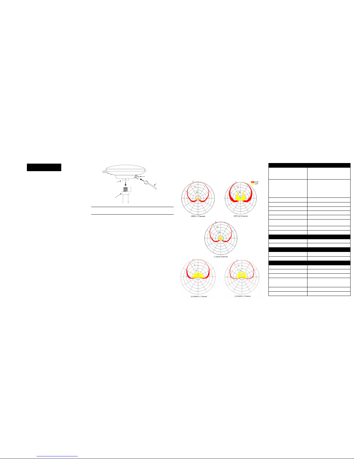
INSTALLING THE ANTENNA
The metal adapter on the bottom of the antenna is fixed in place.
Do not attempt to remove it.
After a site has been selected, install the antenna as follows:
1. Verify that the thread on the mount does not extend more
than 7/8" (22 mm) to ensure the plastic inside the antenna
receptacle is not damaged when the mount is inserted. If it
extends further than 7/8" (22 mm), add two jam nuts to
shorten the exposed thread, ensuring the nuts are well tightened.
2. Align the mount thread with the metal adapter on the bottom
of the antenna and rotate the antenna clockwise until it is
securely screwed to the mount. Using a wrench, tighten the
adapter to the mount.
3. Remove the dust cap from the antenna’s TNC connector.
4. Attach the male TNC connector of the coaxial cable to the
antenna’s TNC connector.
5. Attach the other end of the coaxial cable to the antenna input
port of the receiving device, which must provide power as
detailed in the SPECIFICATIONS section of this guide. All
NovAtel GPS receivers provide the necessary power
through their antenna RF connectors.
ANTENNA CARE
The GPS-701-GGL and GPS-702-GGL are designed to withstand the elements, including rain, snow, and dust. However, to
ensure your antenna performs optimally, keep the radome (the
top surface of the antenna) clean and brush off any ice and
snow. In addition, ensure the TNC connector remains clean and
dry and replace the dust cap when a cable is not connected.
ELEVATION GAIN PATTERN
Table 1: SPECIFICATIONS
USER GUIDE
5/8 x 11
thread
"
3/8 - 7/8"” ( )9 - 22 mm
Antenna Mount
Metal
adapter
Jam nuts
or flange
TNC connector
Coaxial
cable
RF
3 dB pass band (typical)
L-Band 1545 ± 20.0 MHz
L1: 1588.5
± 23.0 MHz
L2: 1236.0
± 18.3 MHz
Out-of-band rejection (typical)
± 150 MHz (L1 centred)
± 100 MHz (L2 centred)
± 250 MHz (L1 centred)
± 200 MHz (L2 centred)
30 dBc
30 dBc
50 dBc
50 dBc
Gain at zenith (
θ = 90°) (min)
LB/L1:+5 dBic L2:+2 dBic
Gain roll-off (zenith to horizon) LB/L1:13 dB L2: 11 dB
LNA gain (typical) 29 dB
Polarization Right-hand circular
Noise figure (typical) 2.5 dB
L1-L2 differential propagation
delay (maximum)
5 ns
Nominal impedance 50 Ω
VSWR ≤ 2.0 : 1
POWER
Input voltage 4.5 - 18.0 VDC
Current (typical) 35 mA
PHYSICAL
Diameter
185 mm (7.28")
Weight 500 g (17.6 oz)
ENVIRONMENTAL
Maximum altitude 9000 m (29527.5 ft)
Operating temperature -40°C to +85°C (-40°F to +185°F)
Storage temperature -55°C to +85°C (-67°F to +185°F)
Vibration
Random: MIL-STD-202F Method
214, Test Curve A
Sine: SAEJ1211, Section 4.7
Salt spray MIL-STD-810F Method 509.4
Ingress protection IPX6 and IPX7
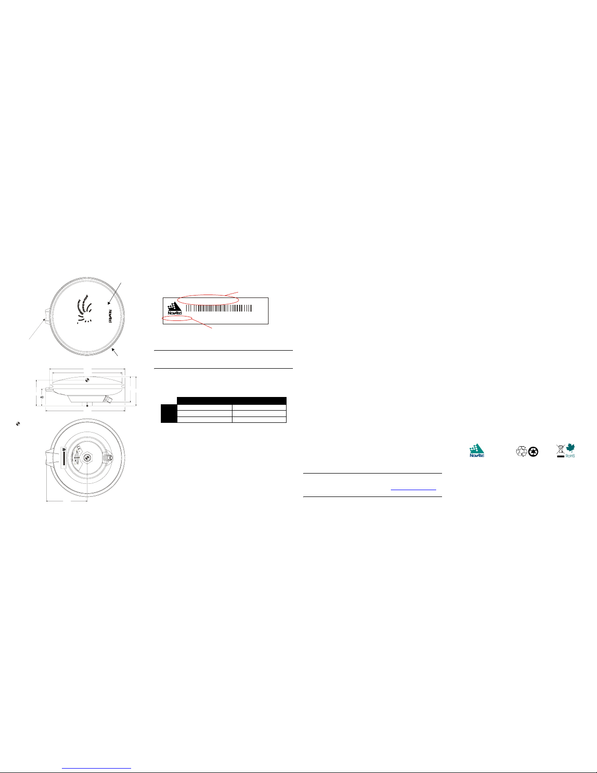
MECHANICAL DRAWINGS PHASE CENTER
Please refer to the Mechanical Drawings on the previous panel
and the close-up of the label below before reading this section.
Height = Vertical phase center offset from antenna reference
point or antenna reference plane (ARP)
Only integer hardware revisions affect the phase center offsets. For
example, the numbers given for hardware revision 2.02 are applicable to an antenna labelled H/W Rev: 2.00, 2.04, 2.12 and so on.
Table 2 shows typical absolute and relative offset numbers for
the current GPS-702-GGL antenna model.
Table 2: Height
If you need any further advice on this matter, please visit our
website at www.novatel.com. Other methods of contacting
Customer Service can be found on the last panel of this guide.
WARRANTY POLICY
NovAtel Inc. warrants that its Global Positioning System (GPS) products
are free from defects in materials and workmanship, subject to the
conditions set forth below, for the following periods of time:
GPSAntenna™ Modules: One (1) Year
Cables and Accessories: Ninety (90) Days
Date of sale shall mean the date of the invoice to the original customer
for the product. NovAtel's responsibility respecting this warranty is
limited solely to product repair at an authorized NovAtel location only.
Determination of repair will be made by NovAtel personnel or by tech-
nical personnel expressly authorized by NovAtel for this purpose.
The foregoing warranties do not extend to
(i) nonconformities, defects or errors in the products due to accident,
abuse, misuse or negligent use of the products or use in other than a
normal and customary manner, environmental conditions not
conforming to NovAtel’s specifications, or failure to follow prescribed
installation, operating and maintenance procedures, (ii) defects, errors
or nonconformities in the products due to modifications, alterations,
additions or changes not made in accordance with NovAtel’s specifications or authorized by NovAtel, (iii) normal wear and tear, (iv) damage
cause by force of nature or act of any third person, (v) shipping damage;
or (vi)service or repair of product by the dealer without prior written
consent from NovAtel.
In addition, the foregoing warranties shall not apply to products designated by NovAtel as beta site test samples, experimental, developmental, preproduction, sample, incomplete or out of specification
products or to returned products if the original identification marks have
been removed or altered.
The warranties and remedies are exclusive and all other warranties,
express or implied, written or oral, including the implied warranties of
merchantability or fitness for any particular purpose are excluded.
NovAtel shall not be liable for any loss, damage or expense arising
directly or indirectly out of the purchase, installation, operation, use or
licensing or products or services. In no event shall NovAtel be liable for
special, indirect, incidental or consequential damages of any kind or
nature due to any cause.
There are no user-serviceable parts in the GPS Antenna and no maintenance is required. If the unit is faulty, replace with another unit and
return the faulty unit to NovAtel Inc. You must obtain a RETURN MATERIAL AUTHORIZATION (RMA) number by calling NovAtel Customer
Service at 1-800-NOVATEL (U.S. and Canada only) or 403-295-4900
before shipping any product to NovAtel or a dealer. Once you have
obtained an RMA number, you will be advised of proper shipping procedures to return any defective product. When returning any product to
NovAtel, please return the defective product in the original packaging to
avoid damage.
Before shipping any material to NovAtel or Dealer, please obtain a
Return Material Authorization (RMA) number from the point of purchase. You may also visit our website at http://www.novatel.com
and select Support | Repair Request from the menu.
WEEE NOTICE
If you purchased your GPS-701-GGL/GPS-702-GGL in Europe, please
return it to your dealer or supplier at the end of its life. The objectives of
the European Community's environment policy are, in particular, to
preserve, protect and improve the quality of the environment, protect
human health and utilise natural resources prudently and rationally.
Sustainable development advocates the reduction of wasteful consumption of natural resources and the prevention of pollution. Waste electrical and electronic equipment (WEEE) is a regulated area. Where the
generation of waste cannot be avoided, it should be reused or recovered for its material or energy. WEEE products may be recognised by
their wheeled bin label.
RoHS NOTICE
The GPS-701-GGL and GPS-702-GGL are compliant with the
European Union (EU) Restriction of Hazardous Substances
(RoHS) Directive 2002/95/EC.
PATENT NOTICE
The GPS-701-GGL and GPS-702-GGL are manufactured and
protected under U.S. Patents #6,445,354 B1, #6,452,560 B2 and
(patent pending) File No 16437-0225.
QUESTIONS OR COMMENTS
If you have any questions or comments regarding your GPS701-GGL or GPS-702-GGL antenna, please contact NovAtel
Customer Service using one of methods provided below.
Email: support@novatel.ca
Web: www.novatel.com
Phone: 1-800-NOVATEL (U.S. & Canada)
403-295-4900 (International)
Fax: 403-295-4901
© Copyright 2007 NovAtel Inc. All rights reserved. Unpublished rights reserved under
international copyright laws. Recyclable.
OM-20000117 Rev 1 March 31, 2007
TOP
VIEW
BOTTOM
VIEW
1
00
60.6
69.
1
Ø185
Ø170
194.5
SIDE
VIEW
Height
A
ll dimensions are in millimeters (mm
)
where 1 inch = 25.4 mm
= PHASE CENTER
Tape measure
station
H/W Rev: 1.00 P/
N
: 0101xxxx
MADE I
N
CA
N
ADA www.novatel.ca
N
VH99999999
GPS-70x A
N
TE
N
N
A
ARP
100 mm
40 mm
A
RP
4
.
5
-
1
8
V
D
C
5
0
m
A
m
a
x
.
65 mm
GNSS + L-BAND
GPS-701-GGL =Blue
GPS-702-GGL =Grey
L-band Graphic
Absolute (GEO++)
Relative (NGS/IGS)
L1
63 mm (2.48”) 81 mm (”)
L2
61 mm (”) 72 mm (”)
Avg.
62 mm (”) N/A
H/W Rev: 1.00 P/N: 0101xxxx
MADE IN CANADA www.novatel.ca
NVH99999999
GPS-70x ANTENNA
Antenna model
Hardware Revision
 Loading...