

Novatel GPS-302L-A User Manual
1
GPS-302L-A
GM-14915161 Rev 2 March 2018
USER GUIDE
The GPS-302L-A is an active antenna designed to operate at the GPS L1 and L2 frequencies, 1575.42
and 1227.60 MHz, GLONASS L1 1592.95 – 1610.38 MHz frequencies and across the L-Band from 1525
to 1560 MHz. This guide provides the information needed to install and use the antenna.
ADDITIONAL EQUIPMENT REQUIRED
• A device with an antenna input port that both receives the RF signal and provides 3.8 to 6.0 VDC to
the antenna is required to set up the GPS-302L-A. (NovAtel GNSS receivers provide the necessary
power through their antenna RF connectors.)
• Coaxial cable with a male TNC connector
INSTALLING THE ANTENNA
Both the input DC power and the output RF signal flow over a single coaxial cable connected to the
antenna's TNC female connector.
The antenna is attached to a surface by means of an ARINC-743 Bolt Pattern.
Four screws pass through the housing of the antenna.
Install the antenna as follows:
1. Place the o-ring into the groove on the antenna base (o-ring supplied).
2. Drill the mounting holes and the connector hole on the surface. Refer to the Mechanical Drawings
section of this guide for details on the ARINC-743 mounting pattern.
The integrator of this antenna is responsible for ensuring antenna installation meets all the
overall integrated system requirements.
Refer to Section 307 of www.faa.gov/documentLibrary/media/Advisory_Circular/
AC%2043.13-2B.pdf for information about antenna bonding in aircraft applications.
User-supplied o-ring grease can be used to hold the o-ring in the groove during installation.
2
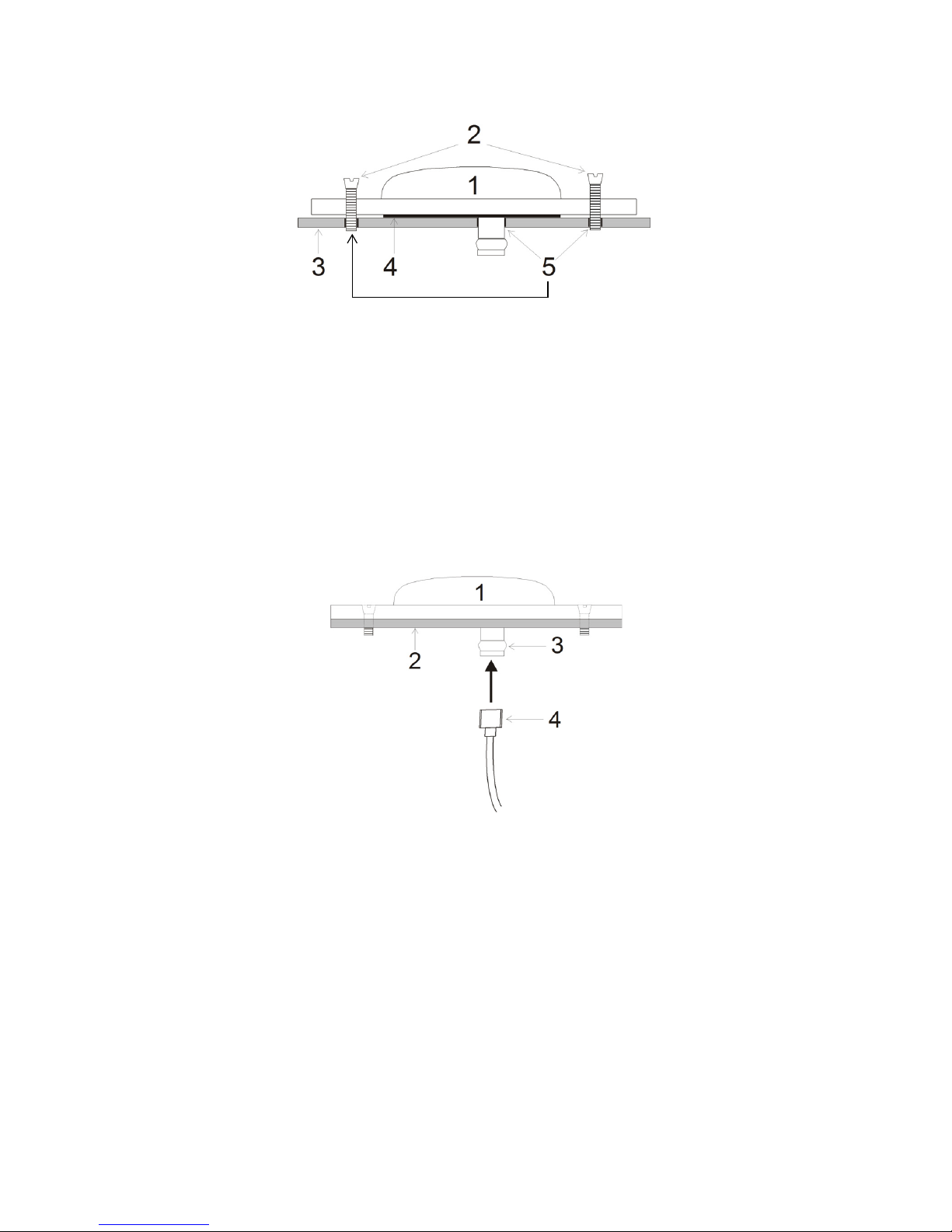
3. Attach the antenna to the surface using the four mounting screws supplied. The o-ring will compress
and create a seal between the surface and the antenna.
Ref. # Description
1 Antenna
2 Countersink screws
3 Mounting surface
4 O-ring
5 Drilled mounting holes
4. Remove the dust cap from the antenna’s TNC connector.
5. Attach the male TNC connector of the coaxial cable to the antenna’s TNC connector.
Ref.# Description
1 Antenna screwed into place
2 Surface
3 TNC connector (male)
4 Coaxial cable (female)
3
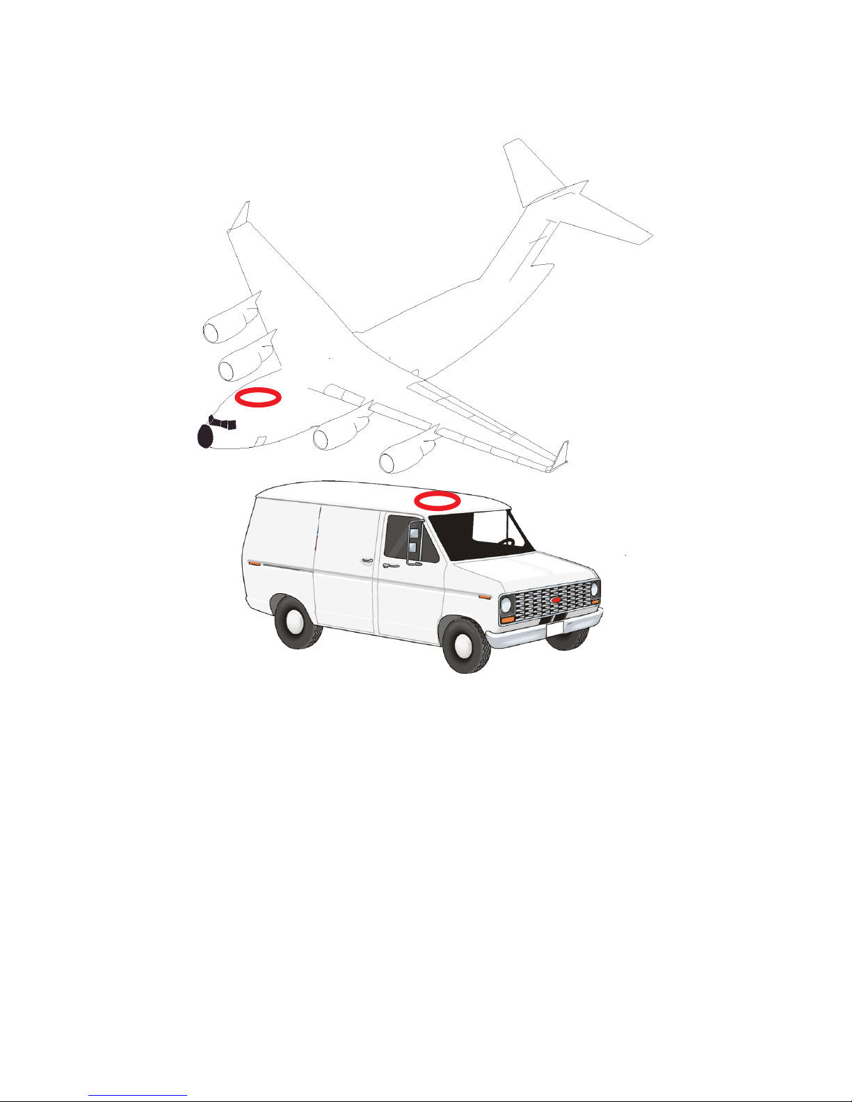
6. Attach the other end of the coaxial cable to the antenna input port of the receiving device. The
receiving device must be able to provide power as detailed in the SPECIFICATIONS section of this
guide. All NovAtel GNSS receivers provide the necessary power through their antenna RF connectors.
The graphic above shows examples of where the GPS-302L-A antenna may be located on an aircraft or
vehicle (not to scale).
ANTENNA CARE
The GPS-302L-A is designed to withstand the elements, including rain, snow and dust. However, to ensure
your antenna performs optimally, keep the radome clean and brush off any ice and snow. In addition,
ensure the TNC connector remains clean and dry and replace the dust cap when a cable is not connected.
 Loading...