

Novatel GPS-302-40 User Manual
1
GPS-302-40
GM-14915159 Rev 1 April 2018
USER GUIDE
The GPS-302-40 antenna is designed for airborne use, but works in any mobile application.
The GPS-302-40 is an active GPS antenna, 89.6 mm (3.53 inches) in diameter and operates at the GPS
L1 frequency of 1575.42 MHz and GPS L2 frequency of 1227.60 MHz. The antenna is a spherical radius
molded radome that provides enhanced protection against rain and ice.
The antenna includes the following:
• internal 40 dB low noise amplifier
• bias voltage from 3.8 – 6.0 VDC for operation
• band pass filtering
• DC bias provided through the coaxial connector
NovAtel offers optional coaxial cables of various lengths to connect the antenna and NovAtel GNSS
receivers.
This guide provides the basic information you need to install and begin using your new antenna.
ADDITIONAL EQUIPMENT REQUIRED
• A device with an antenna input port that both receives the RF signal and provides 3.8 – 6.0 VDC to
the antenna is required for the GPS-302-40. NovAtel GNSS receivers provide the necessary power
through their antenna RF connectors.
• Coaxial cable with a male TNC connector
INSTALLING THE ANTENNA
Both the input DC power and the output RF signal use a single coaxial cable connected to the unit's TNC
female connector.
The antenna can be attached to a surface with a square, four bolt, 1.9-inch space mounting pattern as
shown in the Mechanical Drawings section of this guide. Four screws pass through the antenna housing.
The integrator of this antenna is responsible for ensuring antenna installation meets all the
overall integrated system requirements.
Refer to Section 307 of www.faa.gov/documentLibrary/media/Advisory_Circular/
AC%2043.13-2B.pdf for information about antenna bonding in aircraft applications.
2
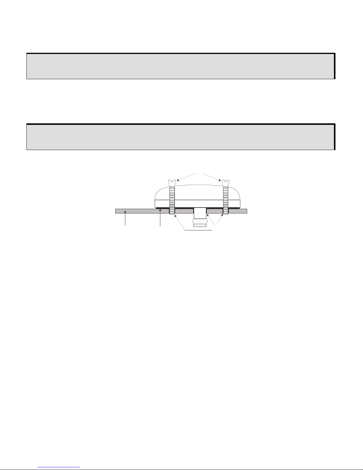
To install the antenna:
1. Install the supplied o-ring into the groove on the antenna base.
2. Drill and tap the mounting holes and drill the connector clearance hole on the mounting surface. See
the Mechanical Drawings section for mounting pattern details.
3. Use the four supplied mounting screws to attach the antenna to the mounting surface. The o-ring compresses and creates a seal between the surface and the antenna.
Ref. # Description
1 Antenna
2 Countersink screws
3 Mounting surface
4 O-ring
5 Drilled mounting holes
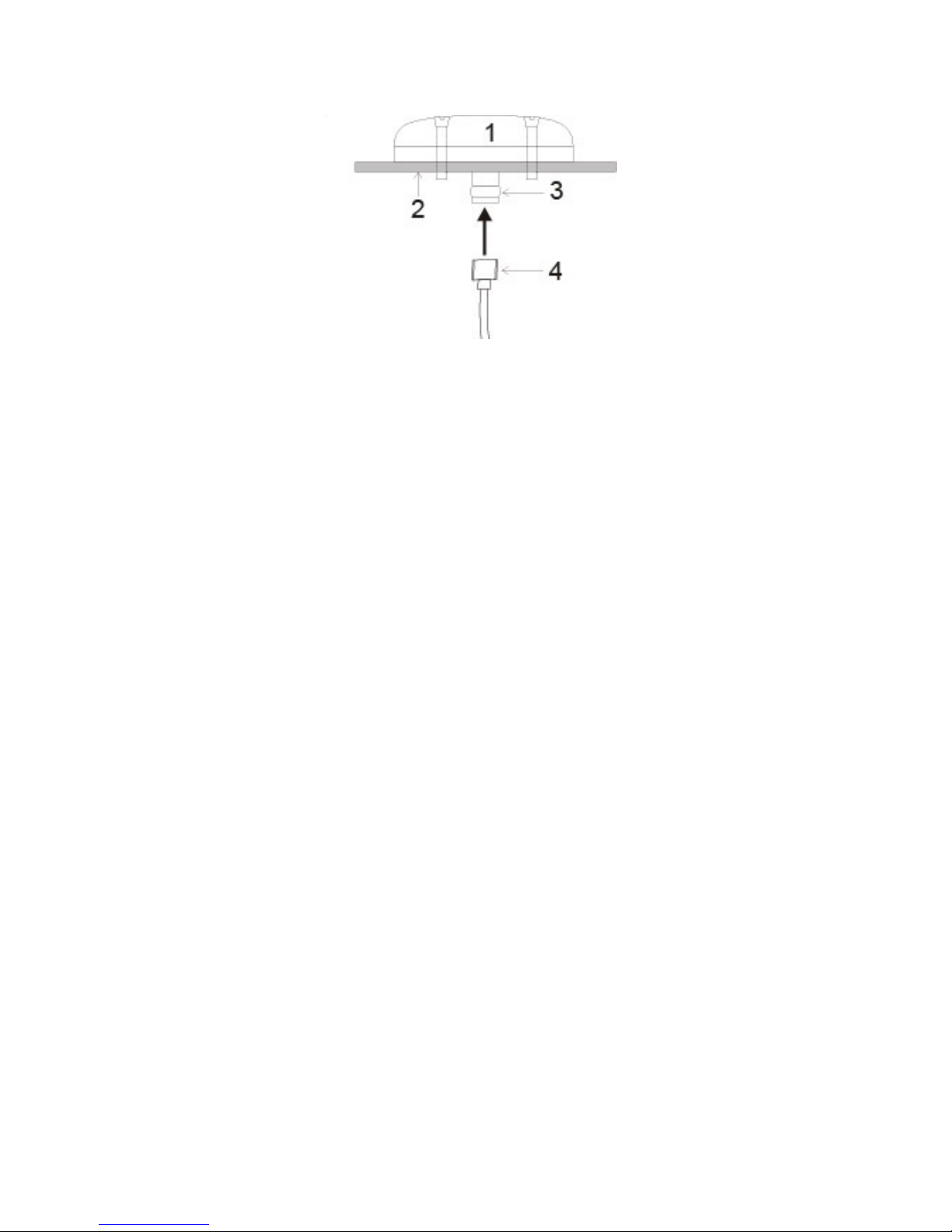
4. Remove the dust cap from the antenna’s TNC connector.
User-supplied o-ring grease can be used to hold the o-ring in the groove during
installation.
NovAtel recommends thread-locker (not included) on the mounting screws.
1
2
3 4
5
3
5. Attach the coaxial cable’s male TNC connector to the antenna’s TNC connector.
Ref.# Description
1 Mounted antenna
2 Mounting surface
3 TNC connector
4 Coaxial cable
6. Attach the other end of the coaxial cable to the antenna input port on the receiving device. The
receiving device must be equipped to provide power as detailed in the SPECIFICATIONS section of
this guide. All NovAtel GPS receivers provide the necessary power through the antenna RF
connectors.
 Loading...