

Page 1
InstructionInstruction
Instruction
InstructionInstruction
ManualManual
Manual
ManualManual
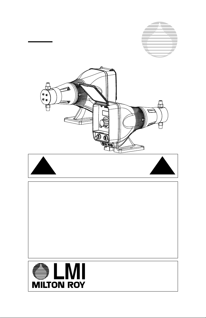
Series HH
Electronic Metering Pumps
Carefully read and understand all precautions
!
CAUTION
For file reference, please record the following data:
before installing or
servicing any metering pump.
!
CAUTION
Model Number:______________________________
Serial Number:_____________________________
Installation Date:____________________________
Installation Location:_________________________
When ordering replacement parts for your LMI Series HH
Metering Pump or Accessory, please include complete Model
Number and Serial Number of your unit.
201 Ivyland Road
Ivyland, PA 18974 USA
TEL: (215) 293-0401
FAX: (215) 293-0445
http://www.lmipumps.com
ISO 9001 Certified
1983.A 03/04
Page 2

Contents
1.0 Introduction ................................................................ 4
1.1 Spare Parts ........................................................... 4
2.0 Unpacking ................................................................ 5
3.0 HH9 Features ................................................................ 6
4.0 How to Interpret the Model Number ............................... 7
5.0 Pre-Installation Instructions ............................................ 8
6.0 Installation Instructions................................................... 9
6.1 Pump Location ...................................................... 9
6.2 Pump Mounting ................................................... 10
6.3 Plumbing ............................................................. 10
6.4 External Control Connections.............................. 11
6.5 Priming & Operation ............................................ 12
7.0 Output Adjustment Controls ......................................... 13
7.1 Pressure Control Adjustment............................... 13
7.2 Speed Adjustment ............................................... 13
7.3 Stroke Adjustment ............................................... 14
7.4 Calibration ........................................................... 14
8.0 Accessories .............................................................. 15
8.1 8-pin Cable.......................................................... 15
8.2 Optional 4-pin Cable HH9.................................... 16
8.3 Optional 4-pin Cable HH7.................................... 16
8.4 Optional "Hall Effect" Cable................................. 17
9.0 Checking Pump for Proper Zero Position ..................... 18
9.1 Push On Knob..................................................... 18
10.0 Keypad / Display HH9 .................................................. 20
10.1 LCD Screen......................................................... 20
10.2 Start / Stop .......................................................... 21
10.3 Up & Down Key................................................... 21
10.4 Mode Key............................................................ 21
11.0 Operation of the Series HH9 ........................................ 22
11.1 Pump Start/Stop.................................................. 22
11.2 Speed .............................................................. 23
11.3 Pressure Level Control........................................ 24
11.4 Keypad Lock ....................................................... 24
11.5 Low-Level Switch ................................................ 25
2
Page 3

12.0 External Control Modes HH9........................................ 25
12.1 Programming Pulse Divide.................................. 26
12.2 Programming Pulse Multiply................................ 27
12.3 Programming mA Response ............................... 28
12.4 Programming Points 1&2 (SPM) ......................... 29
12.5 Programming Points 1&2 (SPH).......................... 31
13.0 Advanced Features and the Setup Menu HH9 ............. 33
13.1 Accessing the Setup Menu.................................. 34
13.2 Menu Items ......................................................... 34
13.2.1 Batch Accumulate.................................. 34
13.2.2 Automatic Voltage Compensation.......... 35
13.2.3 Flow Monitoring ..................................... 35
13.2.4 Input Signal Pulse Width (Debounce) .... 35
13.2.5 Activate the Intergral Blowdown Feature . 36
14.0 Troubleshooting ........................................................... 38
Appendix A:Input/Output Descriptions .................................... 42
Appendix B:Summary of Error Messages............................... 47
3
Page 4

1.0 Introduction
LMI is the world’s most versatile manufacturer of economical and
efficient metering pumps. This manual addresses the installation,
maintenance and troubleshooting procedures for the HH Series
manually and externally controlled pumps. LMI has a worldwide
network of stocking representatives and authorized repair centers to
give you prompt and efficient service.
The Series HH9 electronic metering pump offers an extensive range of
features, including microprocessor control for accurate and flexible
automation in response to instrument signals. The microprocessor
design employs a customized liquid crystal display (LCD) and tactile
response keypad. The "state-of-the-art" surface mount electronics are
fully encapsulated to ensure protection in its working environment. All
external inputs and outputs are opto-isolated from the microprocessor.
Please review this manual carefully. Pay particular attention
to warnings and precautions. Always follow good safety
procedures, including the use of protective clothing, eye and
face protection.
1.1 Spare Parts
LMI recommends replacing all components subject to wear and tear
on an annual basis. RPM Pro Pacs™ and spare part kits are available
from your local LMI Master Stocking Distributor. The spare parts
kit for the HH pump is SP-987.
Figure 1:
LMI Series
HH9 Electronic
Metering Pump
4
Page 5
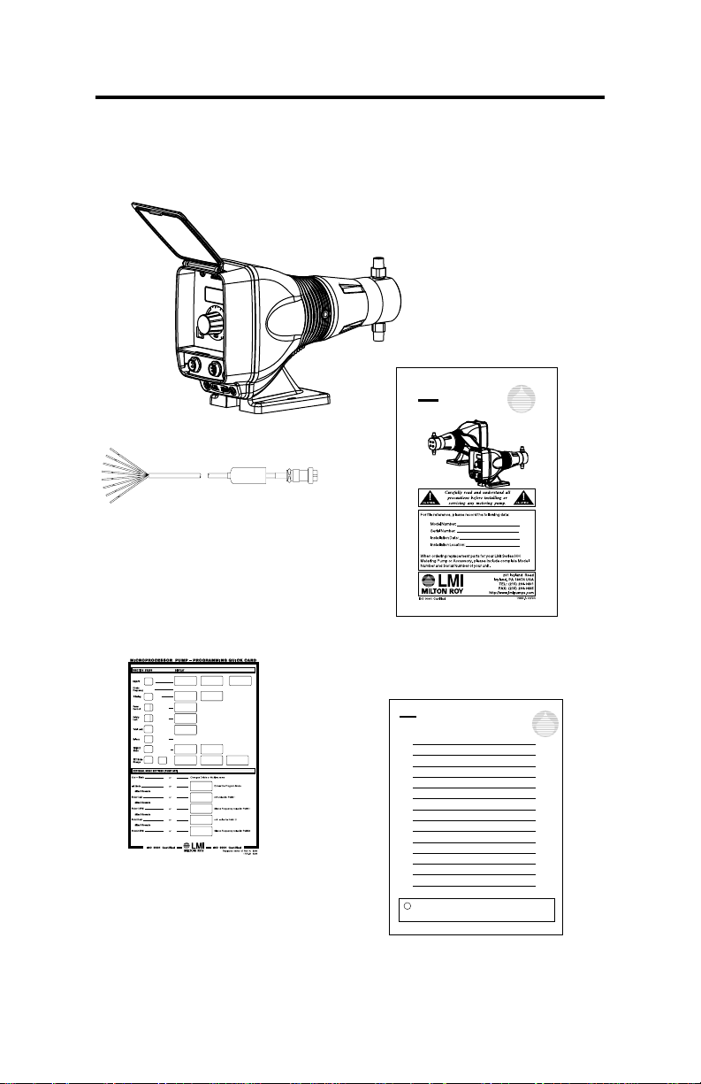
2.0 Unpacking
You should find the following items in the box:
Electronic
Metering Pump
InstructionInstruction
Instruction
InstructionInstruction
Electronic Metering Pumps
8 Pin Cable
(Series HH9 Only
P/N 33738)
ManualManual
Manual
ManualManual
Series HH
Quick
Card
(Series HH9 Only
P/N 1757)
Series HH
Instruction
Manual
(P/N 1983)
Instruction Supplement
LMI
MILTONROY
Instruction
Supplement
Figure 2: Unpacking Items
5
Page 6

3.0 HH9 Features
Stroke frequency adjustment from 0 SPH (strokes per hour) to
100 SPM (strokes per minute).
Internal (manual) or external mode select.
Flexible slope adjustable response to mA input signals.
Divide or multiply (batch) incoming pulses (1 to 999).
Batch accumulate option.
Integral blowdown controller feature.
Keypad locking.
Low-level shutoff with alarm output.
6-level pressure control.
Continuous non-volatile memory (EEPROM)--no battery
required.
Remote ON/OFF control.
Pulse (pacing) output.
Automatic line voltage compensation and over voltage
protection.
Programmable menu for optional features/parameters.
6
Page 7
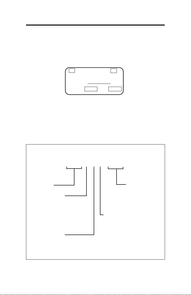
4.0 How to Interpret the Model Number
The silver data plate (located on the front of the pump) tells you how
your pump is configured.
PSI
1.4 A
1000
115 V.A.C.
MODEL # HH931-987
SERIAL #
MAX/
GPH
50/60 HZ.
0.07
Figure 3a : Data Plate
Included on the data plate is the model number of the pump. Each
number in the model number represents the following in Figure 3b.
HHXXX-987
Series
or Model
Control Code
1 = Manual
7 = Instrument
Responsive Manual
9 = Microprocessor/
Instrument
Responsive
Output Codes
1 = 0.14 GPH at 300 PSI
2 = 0.10 GPH at 600 PSI
3 = 0.07 GPH at 1000 PSI
Cord & Voltage Codes
Liquid End
1 = 120 V US plug, UL
2 = 240 V US plug, UL
3 = 230 V DIN plug, CE
5 = 240 V UK plug, CE
6 = 250 V Aust/ NZ plug
7 = 230 V Swiss plug
8 = 120 V No plug, CE
Figure 3b : Model Number Representation
7
Page 8

5.0 Pre-Installation Instructions
Specific precautions should be taken when working
!
CAUTION
Protective Clothing
!
CAUTION
Water Pre-Prime
!
CAUTION
with all LMI metering pumps. Please read this section
carefully prior to installation.
ALWAYS wear protective clothing, face shield, safety
glasses and gloves when working on or near your
metering pump. Additional precautions should be taken
depending on the solution being pumped. Refer to
MSDS precautions from your solution supplier.
All LMI pumps are pre-primed with water when shipped
from the factory. If your solution is not compatible with
water, disassemble the Pump Head Assembly.
Thoroughly dry the pump head, plunger, and check
valve components. Reassemble head assembly
tightening screws in a crisscross pattern. Refill the
pump head with the solution to be pumped before
priming the pump. (This will aid in priming.)
8
Page 9
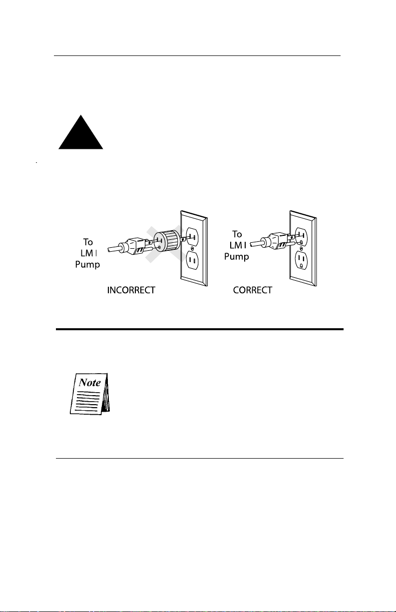
Electrical Connections
WARNING: to reduce the risk of electrical shock, the
metering pump must be plugged into a grounded outlet
!
CAUTION
with ratings conforming to the data on the pump
control panel. The pump must be connected to a good
ground. DO NOT USE ADAPTERS! All wiring must
conform to local electrical codes.
6.0 Installation Instructions
The minimum allowable system pressure for the
HH pump is 200 psi. If your system operates at
a lower pressure, a back pressure valve must be
installed.
6.1 Pump Location
Locate the pump in an area convenient to the solution tank and
electrical supply. The pump should be accessible for routine
maintenance, and should not be subjected to ambient temperatures
above 122°F (50°C).
9
Page 10

6.2 Pump Mounting
The HH pump requires a Flooded Suction installation. The pump
should be securely mounted at the base of the storage tank with the
suction piping sloping downward to the pump.
All piping should be cleaned and blown-out
prior to connection to the HH pump.
6.3 Plumbing
Always adhere to local plumbing codes and
requirements. Be sure the installation does not
!
CAUTION
The HH high pressure metering pump utilizes 1/4" N.P.T.
connections. These connections require the use of Teflon Tape.
When applying the Teflon Tape, make sure it does not extend over
the fitting. This would restrict the flow of chemical.
All piping being attached to the HH must be cleaned and blown out
to prevent debris from entering the Liquid End. A 100 micron
strainer or filter should be installed to prevent any debris in the
chemical from entering the pump.
constitute a cross connection. Check your local
plumbing codes for guidelines. LMI is not
responsible for improper installations.
10
Both the discharge and suction check valves
should be supported while tightening the mating
pipe connections. This is done by placing a
wrench on the check valve flat, to prevent it
from turning and becoming over tightened,
when connecting the pipe.
Page 11
The discharge piping must be installed and supported so that it does
not place a supportive load on the liquid end.
Series HH pumps are capable of developing 1000
!
CAUTION
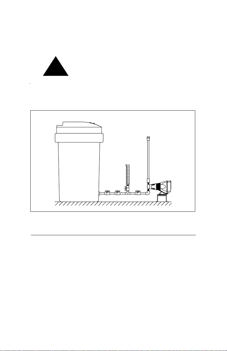
For calibration purposes, it is recommended that a 200 mL graduated
cylinder be piped in-line, on the suction side of the pump (see
Figure 4).
psi of discharge pressure. All piping must have
sufficient rating to withstand maximum pressure.
TANK
Figure 4: Series HH Recommended Installation.
6.4 External Control Connections
The HH7 and HH9 come standard with various electrical connectors.
These are located on the front of the pump. The functions and
appropriate connections are covered in greater detail later in this
manual.
The HH pump comes equipped with a 1/8" NPT port on the bottom
of the liquid end spacer. This port is provided for draining in the
event that the seal stack leaks. Use a 1/8" NPT, Teflon taped
connector to safely route any leakage to a suitable container.
25ml
Cylinder
11
Page 12
6.5 Priming and Operation
LMI performance tests every pump prior to shipping to insure that
it meets the design parameters. This test is performed using water.
Please be advised that the pumps are shipped with water in the
Liquid End. If it is incompatible with the chemical that is being
injected, the head must be dried.
When all of the previously mentioned precautions and safety
regulations required by your facility or local ordinances have been
considered, you may start priming your pump.
The HH precisely injects small amounts of
chemical. Due to this characteristic, the HH will
take a considerable amount of time to prime.
System design may also affect the priming time
The HH9 Control Panel has a Start/Stop button
labeled "Hold for Prime". This key has a timer that
shuts off after one minute of operation. The
lengthy priming time of the HH renders this
function unusable. The priming procedure should
be done with the pump running in the internal
mode.
12
Step 1- Plug in or switch on your pump
Step 2- While the pump is running, turn the stroke dial
knob to 100% and the speed adjustment knob (if equipped)
to 80%.
Step 3- Make sure that any valves are open to allow
chemical to enter the pump head.
Page 13

7.0 Output Adjustment Controls
Once the pump is primed, the output must be adjusted to meet the
requirements of the system. This adjustment is made by varying
both the stroke and speed of the pump.
7.1 Pressure Control Adjustment (HH9 Only):
The pressure control adjustment, unique to LMI, allows for the fine
tuning of your HH9 Pump. This reduces over pumping of chemical
and power consumption while increasing the accuracy and life of
your pump.(See Section 11.3)
7.2 Speed Adjustment:
The HH9 speed control can be adjusted manually, using the keypad
or externally as described in section 11. In either case, the speed
adjustment controls the frequency or rate at which the chemical is
being injected.
The HH1 and HH7 come equipped with a manual speed adjustment
knob. Turning the knob clockwise to the maximum setting increases
the stroke rate up to 100 strokes per minute.
HH7 Only:
When operating the pump in external mode, the
speed control knob should be turned fully counter
clockwise.
13
Page 14

7.3 Stroke Adjustment:
The Stroke Adjustment dial controls the volume of chemical being
injected with each stroke. The 100% setting indicates the maximum
volume per stroke.
The maximum rated output of your pump is
indicated on the data plate. The HH output
control features have been designed to make it
easy for the user to determine the appropriate
speed and stroke settings.
7.4 Calibration
The HH has been designed to inject a precise, repeatable amount of
chemical against system pressure. Because every system is different,
it is necessary to calibrate the pump once it is installed. The
calibration will enable you to fine tune the HH to provide the desired
injection amount.
The HH calibration is done after the pump is fully primed. The
discharge or injection point must be at normal operating pressure
for an accurate calibration to be done.
The suction line should be valved to run off the in-line calibration
cylinder. This cylinder must reproduce the suction pressure applied
by the tank (see Figure 4).
14
Page 15

8.0 Accessories
8.1 8-Pin Cable ( P/N 33738 HH9 Only)
The 8-pin external cable assembly can be used to control stroke
frequency in response to a 0 to 20 mA or 4 to 20 mA instrument
signal. This cable assembly also provides output signals for
pacing (pulse output), alarm (general) and computer alarm.
Figure 5: 8-Pin Cable (P/N 33738)
PIN WIRE SIGNAL
1 Red +15V Output
2 Black -15V Ground
3 V iolet +0-20 or 4-20 mA (+) Input
4 Green -0-20 or 4-20 mA (-) Input
5 Orange Pulse Output
6 Y ellow Alarm Output
7 Brown Flow Input
8 Blue Computer Alarm Output
& Computer Output
Table 1: Pin Out Table - 8-Pin Cable (P/N 33738)
15
Page 16

8.2 Optional 4-Pin Cable (P/N 33796 HH9 Only)
The optional 4-pin external cable is used for connecting incoming
pulse or pacing signals such as those triggered by a manual
switch, reed switch, opto-coupler or by NPN or PNP transistors.
The remote ON/OFF input is also accessed through the
standard 4-pin connector.
Figure 6: 4-Pin Cable (P/N 33796)
PIN WIRE SIGNAL
1 White +15V Output
2 Black Pacing input
3 Green +15V Ground
4 Red Remote ON/OFF
& Computer Input
Table 2: Pin Out Table - 4-Pin Cable (P/N 33796)
8.3 Optional 4-Pin Cable (P/N 28368 HH7 Only)
The optional 4-pin external cable is used for connecting incoming
pulse or pacing signals such as those triggered by a manual
switch, reed switch, opto-coupler or by NPN or PNP transistors.
Figure 7: 4-Pin Cable (P/N 28368)
PIN WIRE SIGNAL
1 White Pacing Input
2 Black Pacing input
3 None None
4 None None
Table 3: Pin Out Table - 4-Pin Cable (P/N 28368)
16
Page 17

8.4 Optional "Hall Effect" Cable (P/N 33833)
An optional cable assembly is available for pacing your pump
directly from an LMI Flowmeter fitted with a Hall Effect
sensor. This cable connects to the Flowmeter as shown in
Figure 8 (There is no need for a Programmable Divider; its
function is built into the pump).
Figure 8: Optional "Hall Effect" Cable (P/N 33833)
17
Page 18

9.0 Checking Pump for Proper Zero Position (Stroke Knob)
1.With pump running, turn stroke knob counter-clockwise
toward zero or end of black or red band on dial.
2. LISTEN to the clicking as the pump is running. The pump
should operate quietly at the zero position (no clicking).
3. If the pump continues to click at zero or stops clicking before
zero is reached, the pump zero must be reset.
9.1 Push on Knob
Re-Zeroing and Stroke Knob Disassembly and Assembly
1.Remove stroke knob from the pump by grasping the knob
firmly and pulling it toward you.
2.Pry off the yellow cap.
3.Place the knob on a flat surface.
4.Using needle-nose pliers, squeeze the inner section together
while lifting the outer section up.
5.Push the inner section back onto the “D” shaped stroke shaft.
6.With the pump running, zero the pump by turning the inner
section of the knob counter-clockwise
clicking.
7. Position the outer section of the knob so that the pointer aligns
with zero on the nameplate or end of the black or red band.
8. Push down on the outer section (a snap sound indicates parts
are locked together).
9. Replace the yellow cap over the outer section of the knob,
aligning the tabs on the cap with the slots inside the knob.
18
until the pump stops
Page 19

Figure 9: Stroke Knob Assembly
19
Page 20

10.0 Keypad/Display: Description and
Function (HH9 Only)
mA EXT
X INT
Figure 10: HH9 Keypad
10.1 LCD Screen
MIN
P12:FLOW
The LCD screen is the window in which all values and menu choices
are displayed (see Figure 11).
FLOW
Figure 11: Liquid Crystal Display
20
Page 21

10.2 Start/Stop
STOP
The (Start/Stop) key turns the pump on or off. If the pump
START
STOP
START
is not running, pressing this key will cause the pump to start
running. The symbol appears on the display while the pump
is running. Each time the pump strokes, the symbol clears. If
the pump is running, pressing the (Start/Stop) key will stop
STOP
START
the pump.
10.3 Up and Down Key
Use the (Up) and (Down) keys when: changing the stroke
frequency; altering the pressure level; activating and deactivating
the keypad lock; programming the divide and multiply values;
accessing the setup menu; and changing certain parameters included
in the setup menu. All of these functions are covered in greater detail
later in this manual.
MODE
E
10.4 Mode Key
MODE
I
Use the (Mode) key when: changing to or from external or
N
T
I
N
N
T
T
E
N
T
internal mode; accessing the pressure level; activating and
deactivating the keypad lock; and accessing specific advanced
features in the setup menu.
21
Page 22

11.0 Operation of the Series HH9
These pumps feature EEPROM nonvolatile memory. The pump will
always power up in the last used mode. When shipped from the
factory the pump will power up in the "Internal" (manual) mode,
with the pump OFF and a speed setting of 100 SPM.
If the power to the pump is cut less than 15 seconds after the
last programmed values have been set, the latest changes
will NOT be stored in nonvolatile memory. Allow at least 15
seconds before disconnecting from power to ensure that the
latest changes are stored.
11.1 Pump Start/Stop
Press the
STOP
(Start/Stop) key to start or stop the pump. When the
START
pump is OFF, the LCD screen will alternate between
INT
every 16 seconds. When you start the pump, the
MIN
symbol appears on the LCD
the symbol disappears. Press the
INT
. Each time the pump strokes,
MIN
STOP
(Start/Stop) key again
START
to stop the pump.
"INT" signifies that the pump is in the "Internal" (Manual)
mode.
INT
and
22
Page 23

11.2 Speed
The speed may be changed with the pump ON or OFF. To increase
or decrease the speed, press or hold the
(Up) or (Down)
key. The range runs from 0 SPH to 100 SPM. While normally the
speed will be set in SPM, if settings of SPH are desired, hold the
(Down) key until the display reads 0, then continue to hold it for an
additional three (3) seconds. The display will then show H60, which
is 60 SPH. The speed can be further reduced to 0 SPH with the
(Down) key.
For example:
INT
MIN
INT
MIN
+3 sec
INT
23
Page 24

11.3 Pressure Level Control
The maximum pressure rating of your pump can be adjusted to
reduce pulsation shock in your discharge line. The pumps have a 6point pressure control scale. The minimum setting is 0 and the
maximum is 5. To access the pressure setting, press the
MODE
I
N
TT
(Mode) key and (Up) key at the same time and hold for two (2)
seconds. The current pressure setting
may be altered
MIN
using the (Up) or (Down) keys.
The pressure may be changed with the pump ON or OFF and in
either Internal or External mode.
11.4 Keypad Lock
The pump has two (2) lock modes to prevent casual tampering. The
small "LOC" de-activates all key functions except
Stop) and Prime. To activate this "LOC" mode, press the
STOP
START
(Start/
MODE
I
N
TT
(Mode) key and (Down) key at the same time and hold for two
(2) seconds. The LCD will read for five (5) seconds and
then return to the previous display. This display reappears when any key except the
STOP
(Start/Stop) key is pressed.
START
E
X
E
X
The large "LOC" disables all keypad entries, including Start/Stop.
Activate this by pressing the Mode, Down, and Up keys at the same
time and holding for two (2) seconds. The LCD will read
for five (5) seconds and then return to the previous display. This
display re-appears whenever any key is pressed.
MODE
I
E
X
To de-activate either lock mode, press the
N
(Mode) key and
TT
(Down) key at the same time, and hold for two (2) seconds. The
or will disappear.
24
Page 25

11.5 Low-Level Switch (P/N 29190)
When the Low-Level Switch is fitted to the pump and a fault
condition exists, the "E1" error code will flash on the LCD screen
INT
.
MIN
For more information on the Low-Level Switch, see the LowLevel Switch Assembly information sheet (P/N 1368).
When a fault condition exists, the pump is stopped and the alarm
and computer alarm lines are activated to allow remote monitoring.
After clearing the fault (by filling the tank), the pump will
automatically restart.
12.0 External Control Modes for HH9
To access the pulse divide, pulse multiply or milliamp response, the
pump must be changed from Internal (manual) mode to External
mode. To do this, first be sure the pump is stopped. Press the
(Mode) key and hold it for three (3) seconds. The LCD screen
displays the last External mode that was programmed. If this is the
first time the pump has been put in the External mode, the factory
default will be displayed on the LCD screen. The factory default
mode is "External Pulse Divide" with a divide value of one (1)
EXT
:
. The display will alternate between SPM and OFF.
MODE
I
N
TT
E
X
25
Page 26

External Mode Select: Pulse Divide, Pulse Multiply, and
mA Response
Any of three external modes may be selected when the pump is
stopped by pressing and holding the
MODE
I
E
X
N
(Mode) key and
TT
STOP
START
(Start/Stop) key for five (5) seconds, then releasing. As noted
above, the default is Pulse Divide. Pressing and releasing these
EXT
keys brings you to the Pulse Multiply mode
X
. In this mode,
the LCD screen alternates between the pulse multiply value and
OFF. Pressing and releasing these keys one more time brings you
to the third external mode, mA response
mA EXT
. In this mode the
MIN
LCD screen alternates between SPM and the mA value.
Summary of External Mode Select
MODE
I
E
X
N
STOP
+
TT
START
For 5 Seconds
mA EXT
MIN
EXT
:
MODE
I
E
X
N
For 5 Seconds
+
TT
STOP
START
MODE
I
E
X
N
STOP
+
TT
For 5 Seconds
START
EXT
X
12.1 Programming the Pulse Divide Value
The divide value is altered by using the
( Up) and (Down)
keys. To do this, the pump must be in the External Divide mode and
be OFF. The valid range for the divide value runs from 1 to 999. With
the pump running in the Divide mode, the speed in SPM is calculated
based on the rate of incoming pulses and the divide value, and
EXT
displayed on the LCD screen
If the calculated speed is less than one (1) SPM, the LCD screen
will display 0 SPM. If the calculated speed is GREATER THAN
100 SPM, the E3 error code will be displayed periodically until
the fault condition is corrected
NOT activate the alarm outputs or stop the pump.
26
:
.
MIN
EXT
:
. This error does
MIN
Page 27

12.2 Programming the Pulse Multiply (Batch) Value
The multiply value is altered by using the
(Up) and (Down)
keys to change the value. The pump must be OFF and in the External
Multiply mode. Like the divide value, the valid range for the multiply
value runs from 0 to 999 pulses. When the pump is ON, a single
external pulse will initiate a batch of pump strokes. The number of
EXT
remaining pulses are displayed on the LCD screen
X
. When
0 is reached, the display resets to the multiply value. The pump is
now ready for another pulse input.
If a pulse is received before the countdown to 0 is complete, the E4
error code is displayed, and the pump batch count resets to the
programmed multiply value. The batch countdown then continues
from its programmed value. As the countdown continues, the E4
error code
X
will be displayed intermittently until the fault is
EXT
corrected. The strokes that remained from the first batch are NOT
accounted for. To clear the fault display, the pump must be stopped
and restarted.
To allow true flow proportioning, the speed in the Multiply mode
is equal to the speed set in the Internal (manual) mode. That
is, if the Internal mode speed is set at 60 SPM, in the External
Multiply mode the pump counts down at 60 SPM.
27
Page 28

Batch Accumulate
The Batch Accumulate function allows you to opt to have any
extra input pulses received in the multiply mode accumulate up to
a maximum batch of 999. If Batch Accumulate is enabled and
a pulse is received during the countdown, the programmed
multiply value will be added to the current displayed value. Pulses
causing the maximum batch of 999 to be exceeded will result in
an E4 error message. When Batch Accumulate is enabled, the
LCD screen alternates between the current multiply value and
EXT
"ACC"
X
. The Batch Accumulate function is activated
in the Setup Menu (see Section 13).
12.3 Programming the mA Response
The HH9 pump accepts a 0-20 mA or 4-20 mA signal directly. The
response to this signal is fully programmable. In the mA mode, the
pump speed is determined by the programmed response curve, as
defined by points "P1" and "P2." The factory default set values for
P1 and P2 are (4 mA, 0 SPM) and (20 mA, 100 SPM) respectively.
This is illustrated in Figure 12.
While in the mA mode, the pump speed
mA
are displayed alternately every four (4) seconds while the
mA EXT
and the mA value
MIN
pump is running.
28
Page 29

12.4 Programming Points 1 and 2 (SPM)
To program points P1 and P2, first ensure the pump is in the mA
mode and OFF. If you wish to program the response in "SPM",
switch to the internal mode. The speed must be set to a SPM value
INT
. Return to the External mA mode.
MIN
mA
MIN
P1P1
100
SPM
50
P1
.
0
4
and
12
mA
P2
.
P2
20
P2
MIN
mA
Figure 12
Press either the (Up) or (Down) key. The LCD screen
will display . After five (5) seconds, the display will show
the mA value for P1
mA
. This value may be altered using the
P1
(Up) or (Down) key within five (5) seconds (i.e. )
. Five (5) seconds following the last key press, the stroke rate for
P1 will be displayed
. This value may be altered within five
MIN
P1
(5) seconds using the Up or Down key (i.e. ).
Five (5) seconds after the last key press, the mA value for P2 is
displayed
mA
). Likewise, five (5) seconds after the last key press the
P2
mA
. Edit as described in the above paragraph (i.e.
P2
stroke rate for P2 is displayed. Edit as described above (i.e. ).
The above examples would result in the inverse control profile
shown in Figure 13 on the following page.
29
Page 30

Figure 13
If the mA input goes below the value programmed for P1 or above
the P2 value, the response will "plateau," as indicated by the dotted
lines above.
The valid input range is from 0.5 to 21 mA. Below 0.5 mA, the
pump will be off. Above 21 mA, the E5 error code will be
displayed intermittently .
30
Page 31

12.5 Programming Points 1 and 2 (SPH)
If you wish to program the response in strokes per hour, start by
being in the External mA mode. Next, switch to the Internal mode.
If the Internal setting is in strokes per minute, change to strokes per
hour by holding the
(Down) key until the display reads 0 SPM.
Continue to hold it for another three (3) seconds. The display will
now read SPH
INT
. Set the speed to any SPH value (the actual
setting has no bearing on mA response). Return to the External mA
mode.
In the External mA mode, pressing the
(Down) key or (Up)
key will change the display to . After five (5) seconds, the
display will show the mA value for P1
mA
. This value may be
P1
altered by using the (Up) key or (Down) key within five
(5) seconds (i.e. ). Five (5) seconds following the last key
press, the stroke rate for P1 will be displayed . This value
may be altered within five (5) seconds using the (Up) or
(Down) key (i.e. ).
Five (5) seconds after the last key press, the mA value for P2 will
be displayed
mA
. Edit as described above (i.e.
P2
mA
).
P2
Likewise, five (5) seconds after the last keypress, the stroke rate for
P2 is displayed and may be altered as above (i.e.
).
P2
The above example would result in the inverse control profile shown
in Figure 14 on the following page.
31
Page 32

Figure 14
The valid input range is from 0.5 to 21 mA. Below 0.5 mA, the
pump will be off. Above 21 mA, the E5 error code will be
displayed intermittently .
When programming strokes per hour, the maximum rate is 60.
P1 and P2 must BOTH BE SPM or BOTH BE SPH.
32
Page 33

13.0 Advanced Features and the Setup
Menu for HH9
Advanced features such as Batch Accumulate, Computer Interfacing,
and Automatic Voltage Compensation, may be selected and altered
in the Setup Menu of the Series HH9. The following configuration
chart describes each menu item, its description, and available
settings.
Menu Description/
Item Function Setting Notes
Software Revision Read Only
1 Batch Accumulate 0 = Disable Applies to External Multiply mode
1 =Enable
3 Automatic Voltage 0 = Disable Becomes active two (2) minutes after
Compensation 1 = Enable power up.
6 Input Pulse Width 0-60 Allows pulse widths of 1 to 60 mSec to be
set. Setting of 0 gives a debounce time of
approximately 1 mSec.
7 Integral Blowdown 0 =Disable Allows Activation of the integral blowdown
8 Integral Blowdown 0 to 255 Set solenoid ON time in seconds.
Solenoid ON Time
(Seconds)
9 Integral Blowdown 0 to 255 Set pump ON time in seconds.
Pump ON Time
(Seconds)
1 =Enable feature.
Note:
Allow 15 seconds after programming before disconnecting from power
to ensure latest changes are stored in nonvolatile memory.
33
Page 34

13.1 Accessing the Setup Menu
To access the Setup Menu, ensure that the pump is OFF and in the
Internal mode. Using the
(Up) key, bring the stroke rate to 100
SPM. At this point, keep the (Up) key pressed for five (5)
seconds. The LCD screen then displays the current software
revision, indicating that you have entered the Menu mode .
Press the
MODE
I
E
X
N
(Mode) key to scroll through the Menu Items. Use
TT
the (Up) or (Down) key to enable or disable menu
functions and program values.
To exit the Menu mode, press the
keys are pressed for 13 seconds, the display reverts to
STOP
(Start/Stop) key. Or, if no
START
INT
.
MIN
13.2 Menu Items
13.2.1 Menu Item 1: Batch Accumulate Enable/Disable
Batch Accumulate may be enabled (1) or disabled (0)
. Use the (Up) or (Down) key to change the
selection.
34
Page 35

13.2.2 Menu Item 3: Automatic Voltage Compensation
Menu item 3 enables (1) or disables (0) automatic voltage compensation. This unique feature allows a constant power level to be
delivered to the EPU of the pump, even when the voltage of the
external power source is fluctuating. This results in smooth pump
output in spite of fluctuating voltage and prevents overheating.
Automatic voltage compensation becomes active two minutes
after power up.
13.2.3 Menu Items 4 and 5: Flow Monitoring
These menu items are not applicable to the Series HH9 metering
pump. Menu item 4 must be disabled (0).
13.2.4 Menu Item 6: Input Signal Pulse Width (Debounce)
Menu Item 6 determines the "debounce" period (pulse width) to be
applied to incoming pulse (pacing) signals. The default value is 15,
which corresponds to a debounce value of 60 mSec . Each
unit corresponds to approximately 4 mSec. This means that in order
to be recognized, an input signal must be at least 60 mSec in duration.
This setting may need to be reduced from its maximum setting for
high frequency input pulse signals such as those from a Hall Effect
flowmeter.
35
Page 36

13.2.5 Menu Items 7, 8 and 9 Activate the Integral
Blowdown Feature
These Menu Items will require additional accessories and customer
supplied components.
This Integral Blowdown feature provides cooling tower control from
your LMI microprocessor pump when used in conjunction with a
pulse output type flowmeter (batch mode) or 4-20 mA signal
(milliamp mode). These signals can then be input into the pump to
provide activation of both the pump and a customer supplied solenoid
valve.
LMI's Relay Pack, Model RP-100A, must be ordered separately
to provide power to the customer supplied solenoid.
36
Page 37

A. Batch Mode
Programming Menu
Menu Item 1 Batch Accumulate Select: 0 = (Disable) or
1= (Enable)
Menu Item 7 Integral Blowdown: Select 1 = (Enable)
Menu Item 8 Solenoid ON time: Select 0 to 255 (Seconds)
Select "INT" mode and set the manual strokes per minute.
Select "EXT X" (multiply) mode (batch mode) and program
stroke count.
On receipt of a pulse from the flowmeter, the pump strokes the
programmed number of pulses. The batch value (multiply [X]
value) and manual SPM determines the length of time the pump
will be on.
On receipt of a pulse from the flowmeter, the solenoid valve is
opened. The solenoid remains open for the length of time
programmed in Menu Item 8. If another flowmeter pulse is
received before the above is completed the solenoid ON time
is extended by the time programmed in Menu Item 8.
37
Page 38

14.0 Troubleshooting
PROBLEM POSSIBLE CAUSE
Pump Will Not Prime 1. Pump not turned on or plugged in.
2. Output dials not set properly.
3. Pump suction not flooded.
4. Air trap in suction piping.
5. Too much pressure at discharge.
Pump Loses Prime 1. Solution container ran dry.
2. Pump suction not flooded.
3. Air trap in suction piping.
SOLUTION
1. Turn on pump/plug in pump.
2. Always prime pump with speed at 80% and stroke at 100%.
3. The HH pump requires a flooded suction. Reposition the pump
accordingly.
4. Be sure the suction piping is installed so that there are no air traps
(see section 6.2).
5. Depressurize discharge piping and verify that system pressure is
within the operating pressure of your pump.
1. Refill container with solution and reprime (see Section 6.0).
2. The HH pump requires a flooded suction. Reposition the pump
accordingly.
3. Be sure the suction piping is installed so that there are no air traps
(see section 6.2).
3938
Page 39

Troubleshooting (continued)
PROBLEM POSSIBLE CAUSE
Leakage at
Piping Connection
Low Output or Failure 1. Pump’s maximum pressure rating
to Pump Against is exceeded by injection pressure.
Pressure
Failure to Run 1. Pump not turned on or plugged in.
1. Piping not sealed.
2. Worn seal rings.
3. Solution attacking Liquid Handling
Assembly material.
2. Worn Check Valves.
3. Worn Plunger Seal.
4. Incorrect stroke length.
5. Piping run on discharge may be too
long.
2. EPU failure.
3. Pulser failure.
SOLUTION
1. Apply Teflon tape to NPT threads and tighten piping (see section 6.3).
2. Replace o-rings. Spare Parts (SP-987).
3. Consult your local distributor for alternate materials.
1. Injection pressure cannot exceed pump’s maximum pressure. See
pump data plate.
2. Replace check valve components. Spare Parts (SP- 987).
3. Replace plunger seal. Spare Parts (SP- 987).
4. Check zero on pump/Re-zero pump (see Section 9.0).
5. Longer piping runs may create frictional losses sufficient to reduce
pump’s pressure rating. Consult factory for more information.
1. Turn on or plug in pump.
2. Disassemble pump and measure the resistance of the EPU across the
EPU wires (yellow). For 120v HH pump the coil resistance should be
82 ohm. For 240v HH pump resistance should be should be 330 ohm.
3. The pulser should be replaced if EPU checks out OK. Consult supplier
or factory.
Excessive Pump Output 1. Syphoning. (Pumping downhill).
2. Little or no pressure at injection point.
3. Excessive strokes per minute.
1. Move injection point to a pressurized location or install a back
pressure valve.
2. If pressure at injection point is less than 200 psi (13.8 Bar)a back
pressure valve must be installed.
3. Replace pulser or resistor. Consult factory.
4140
Page 40

Appendix A: Input/Output Description
Pin 1
Pin 2
Black
Black
Black
Black
White
White
White
White
Pin 1
Pin 2
+
-
Pin 1
Pin 2
+
-
Pin 1
Pin 2
+
-
NPN Transistor
Switch
PNP Transistor
Opto Isolator
4-Pin Connector
Pacing (Pulse) Input / Opto-Isolated Input (HH7 and HH9 Only)
Methods of Triggering Pump.
Reference: 4-Pin Cable (P/N 33796) (HH9 Only)
4-Pin Cable (P/N 28368) (HH7 Only)
42
Appendix A
HH9 Only
Switch or transistor must be capable of switching 2mA at
15 VDC. When in the Divide mode, the switch must close then
open to trigger.
Minimum time in low impedance state (i.e. switch closed) is
60 mSec. by default.
Setup Menu Item 6 sets this value in multiples of 4mSec.
Example: Default = 4 X 15 = 60 mSec
Page 41

HH7 Only
Switch or transistor must be capable of switching 2mA at
15 VDC. Minimum time in low impedance state (on) is 50 mSec.
Minimum time in high impedance state (off) is 100 mSec.
Remote On/Off (Opto-isolated Input) (HH9 Only)
Switching this line to ground starts the pump. Releasing this line,
stops the pump. The
STOP
(Start/Stop) key will always override the
START
Remote Start/Stop.
Reference: 4-Pin Cable (P/N 33796)
Pin 4 Red Remote ON/OFF
Pin 3 Green Ground
Switch Closed = Start Pumping
Switch Open = Stop Pumping
Switch must be capable of switching 2 mA at +15 VDC.
Minimum time in low impedance state (i.e. Switch closed) is
approximately one (1) second.
Low-Level Input (P/N 29190) (HH7 and HH9 Only)
Opening the float switch (i.e. breaking the line from ground) stops the
pump and activates the alarm output.
Float Switch Closed - Pump Running
Float Switch Open - Pump Stopped - Alarm Activated
Switch must be capable of switching 2 mA at +15 VDC.
Minimum time in low impedance state (i.e. switch closed) is
approximately 1 second. (For use with LMI Float Switches [P/
N 29190.]
Low-level input can be used as a remote start/stop in the HH7.
Appendix A
43
Page 42

8-Pin Connector (HH9 Only)
Analog 0-20 mA Input
+0 to 20 mA Violet
-0 to 20 mA Green
8-Pin Cable (P/N 33738)
This is reverse polarity protected with a 22 Ohm impedance, a
resolution or 0.1 mA and an accuracy of +/- 0.2 mA typically.
15 v Output
The +15V Output (pin 1 Red) is regulated and capable of delivering
30 mA current.
Alarm Output
This is an opto-isolated open collector Darlington pair capable of
switching 25 mA at +24 VDC to within 1V of ground typically.
Reference: 8-Pin Cable (P/N 33738)
Pin 6 Yellow
GND Pin 2 Black
The output pair turns ON when an alarm condition occurs (i.e. low
level) and remains ON until the alarm condition is cleared.
Appendix A
44
Page 43

Application: Relay Switching
+15V
Pin 1
Red
Alarm Output
Pin 6
Yellow
Load
GND Pin 2 Black
Computer Alarm Output
This is an opto isolated, open collector output capable of switching
2 mA at +24 VDC to within 0.4V of ground typically.
Reference: 8-Pin Cable (P/N 33738)
Pin 8 Blue
GND Pin 2 Black
This output tracks the alarm output (i.e. the conditions for activating
and de-activating this output are the same as for the alarm output).
This output may be used to directly switch small loads such as
computer inputs and low current LEDs. It may also be used to
initiate switching of larger loads if suitable buffer circuitry is
provided.
Appendix A
45
Page 44

Application: Low Current LED Switching
+15V
Pin 1
Red
10K Ohms
Pin 8 Blue
*Low Current LED
1.0 mA = 10 mcd
GND Pin 2 Black
This is an opto-isolated, open collector output capable of switching
2 mA at +24 VDC to within 0.4V of ground typically.
Pacing Output (Opto-isolated Output)
Reference: 8-Pin Cable (P/N 33738)
Pin 5 Orange
GND Pin 2 Black
The output transistor turns ON at the start of a stroke and remains
ON for approximately 100 mSec.
This is an opto-isolated, open collector output capable of switching
2 mA at +24 VDC to within 0.4V of ground typically.
Appendix A
46
Page 45

Appendix B: Summary of Error Messages
(HH9 Only)
E1
E2
FLOW
E3
:
E4
X
E5
FLOW P12
INT
MIN
INT
EXT
MIN
EXT
EXT
is caused by a Low-Level fault with a Low-Level
Switch connected to the pump. The pump is stopped
and the alarm outputs are activated. This operates in all
Internal and External modes. The pump automatically
restarts when the fault is cleared.
indicates that the pump has lost prime. Again, the pump
is stopped and output alarms activated. Item 4 in the
Advanced Menu must be disabled (set to 0), it is not
usable with the HH9 pump.
is displayed in the External mode if the stroke rate
exceeds 100 SPM. The pump is NOT stopped and NO
alarm outputs are activated with this fault. To stop E3
flashing, clear the fault condition, then stop and restart
the pump.
is displayed in the External X (Batch) mode in two
situations. 1) If "Batch Accumulate" is disabled and a
pulse signal is received while the pump is counting
down. The pump is not stopped, and the alarms are not
activated. To clear the E4 message, the pump must be
stopped and restarted. 2) If "Batch Accumulate" is
enabled and the cumulative batch value exceeds 999, E4
will be displayed. The E4 message can only be cleared
if the pump is stopped and restarted.
is displayed in the mA External mode if the mA input
value exceeds 21.0 mA, whether the pump is running or
stopped. Again, the alarms are NOT activated. Once
the mA signal goes below 21.0 mA, the E5 error
message is cleared.
Appendix B
48
Page 46

ISO 9001 Certified
201 Ivyland Road
Ivyland, PA 18974 USA
TEL: (215) 293-0401
FAX: (215) 293-0445
http://www.lmipumps.com
© 2004 LMI Milton Roy - All Rights Reserved
Printed in USA
Specifications subject to change without notice.
49
 Loading...