

Page 1
Page 2

Thank you for choosing the Biomega BioClave
steam sterilizer.
Your steam sterilizer has been CE certified and
designed with durability, reliability, and safety in
mind. It is your responsibility to install this
instrument in conformance with local electrical
codes.
This manual contains important operating and
safety information. Please read and understand
the contents of this manual prior to operating
this instrument.
Instructions manual
Page 3

TABLE OF CONTENTS
1. GENERAL ------------------------------------------------------------ 1
2. TECHNICAL SPECIFICATIONS----------------------------------- 2
3. PACKING CONTENT ----------------------------------------------- 3
4. INSTALLATION ---------------------------------------------------- 4
5. CONTROL PANEL --------------------------------------------------- 5
6
. OPERATION --------------------------------------------------------- 6
6.1 POWER ON ------------------------------------------------------ 6
6.2 FILLING THE DISTILLED WATER ----------------------------- 6
6.3 PREPARING THE MATERIAL FOR STERILIZATION ----- 6
6.4 SELECTING THE STERILIZATION PROGRAM -------------- 7
6.5 RUNNING THE STERILIZATION PROGRAM ----------------- 7
7. DRAINING THE WATER TANKS ---------------------------------- 9
8. ADVANCED SETTING ---------------------------------------------10
9. PRINTER (OPTIONAL) --------------------------------------------11
10. MAINTENANCE -------------------------------------------------- 12
11. TRANSPORT AND STORAGE ----------------------------------- 15
12. ERROR CODES-----------------------------------------------------16
13. SERVICE AND CONTACT---------------------------------------- 17
APPENDIX
1. WATER PROPERTIES / CHARACTERISTICS -------------- 18
2. DIAGRAMS OF THE STERILIZATION PROGRAMS ----- 19
3. ELECTRICAL DRAWING----------------------------------------- 23
4. HYDRAULIC DRAWING ----------------------------------------- 24
Instructions manual
Page 4
1. General
The sterilizer described in this manual is intended for the sterilization
of research tools. It operates automatically with 134°C and 121°C
sterilization temperatures. This sterilizer is in compliance with the
European Directive 93/42/CEE and it has been produced in accordance
with the EN 13060. In addition the chamber has been ASME certified.
1
10
2
11
12
3
13
4
7
8
9
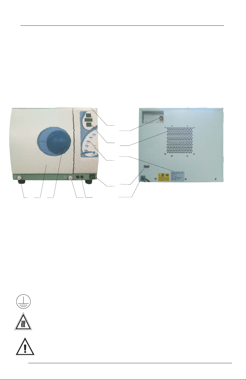
1 Distilled (clean) water tank
2 Display
3 Control panel
4 Power switch
5 F
uses
6
Drain connector, clean water tank
7
Door handle
6
5
14
8 Door
9 Drain connector, used water tank
10 Safety valve
11 Condenser ventilation
12 Serial / Electrical Label
13 Printer port (printer is optional)
14 Power supply cord
For safe operation, please pay close attention to the alert symbols
below which cab be found throughout this manual. Please
carefully read and understand the contents of this manual prior to
operating this instrument.
This symbol represents an electrical caution - ground protection
HOT SURFACE.
This symbol represents a hot surface
This symbol is used to draw the attention of the reader to
particularly important notions for operator safety.
1
1
Instructions manual
Page 5

2. Technical Specifications
(1)Chamber Dimensions: 9in. x 14.2in. / 230mm x 360mm
(2)RatedVoltage:AC110V-120V or 220-240V, 50-60Hz
(3)Nominal power: 1600W (120V) 1250W(220V)
(4)Sterilization Temperature: 121°C / 134°C
(5)Main Fuses:T20A/250V
(6) Capacity of the distilled water tank:
Approx 2.5L (water at level MAX)
(7)OperatingEnvironment: 5 - 40°C
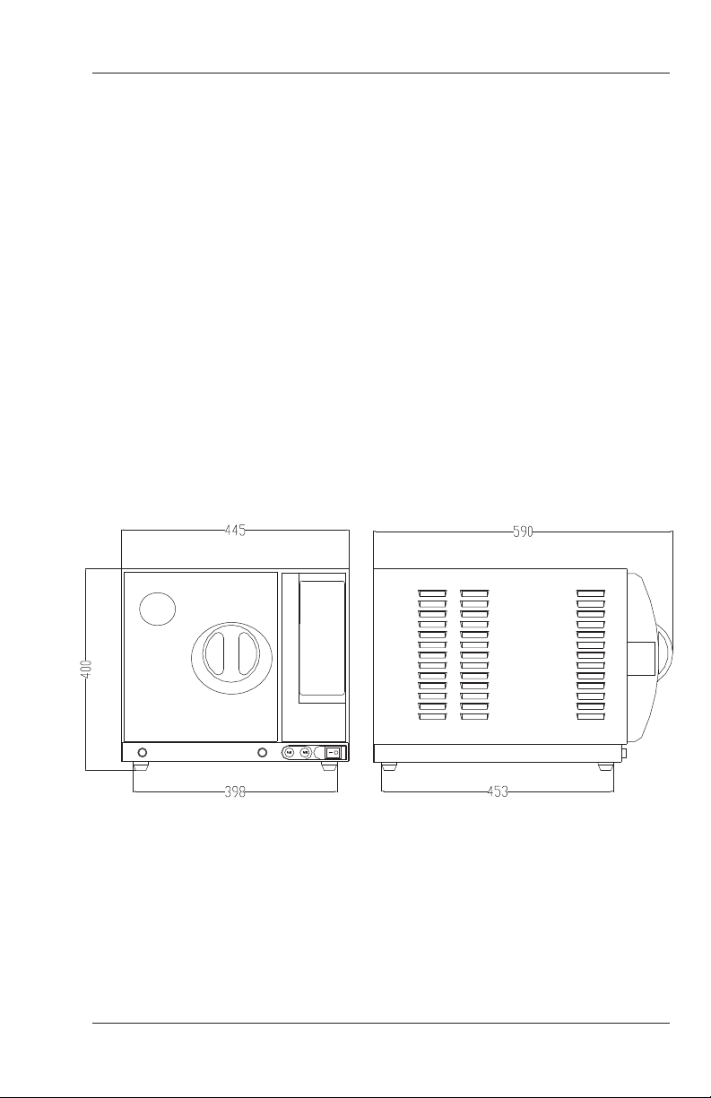
(8)External Dimensions:
17.5in. (width) x 16.7in. (height) x 23in. (depth)
445mm (width) x 400mm (height) x 590mm (depth)
(9)Net weight: 99lbs. /45kg
(10)Noise: <60dB
(11)Relative Humidity: max 80%, non condensing
(12)Atmospheric Pressure: 76kPa -106kPa
Instructions manual
2
Page 6

3. Packing Content
No
1
2
3
4
5
6
7
8
9
10
11
Accessory
16LSteam sterilizer
Loading tray
Tray rack
Tray handling tool
Door adjustment tool
Draining hose
Instructions manual
Spare fuse power
Spare fuse for valve (3A)
Spare fuse for mainboard (1A)
(20A)
Door seal
Quantity
1
3
1
1
1
2
1
2
2
2
1
3
Instructions manual
Page 7
4. Installation
*
Ensure that the sterilizer is installed with 2.5in. (10cm) ventilation space
on all sides of the sterilizer, and 5 in. (20cm) on top side. The clearance
required to open the door is 15.5in. (40cm).
*
The sterilizer should be placed on a level worktable.
*
Do not cover or block the door, ventilation or radiation openings on the
sterilizer.
*
Do not install the sterilizer near a sink or in a location where it is likely to
be splashed.
*
Do not install the sterilizer nearby a heat source.
Instructions manual
Above dimensions are shown in mm.
4
Page 8
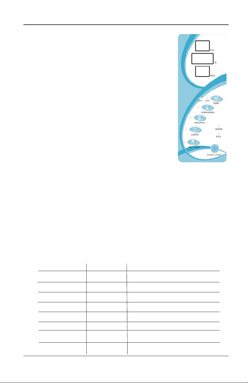
5. Control panel
5.1 Pressure display window.
Displays the current pressure (PSI)
inside the chamber
5.2 Temperature display window.
Display the current temperature (°C)
inside the chamber
5.3 Timer display window
Displays the cycle state (see below)
or the remaining cycle time
5.4 TEMP button
Select the desired sterilization temperature
according to your instrument.
5.5 Sterilization Cycles
UNWRAPPED
-
- WRAPPED
LIQUID
-
- DRY ONLY
(Please seeAppendix 2)
5.6 WATER indication lamp
This lamp will illuminate when the distilled water tank .
is low on water. The tank should then be filled (with distilled water).
5.7 FULLindication lamp
This lamp will illuminate when the used water tank is full.The used water
tank must be drained to continue operation.
5.8 START & STOP button
Once the parameters have been chosen, press this button to start the sterilization
cycle. To cancel or stop the cycle, press and hold this button for 3 sec.
StateCycle
Time Display
Ld
Do
Po
HE
Time in Min.
PL
Ed
E1 - E9
5
State
preheating / loading
Door state
vacuuming
heating
sterilization/drying
exhaust
end
Error state
The machine is prepared for sample loading
Door is open
The machine is vacuuming during a cycle
The machine is in heating mode
Time remaining in program
The machine is cooling and releasing steam.
The cycle is completed, you can open the door
and take out the sterilized sample.
Error - Please see section 12
State description
Instructions manual
Page 9
6. Operation
6.1 Power on
6.1.1 Open the chamber door and remove all inner packing and
accessories.
6.1.2 Plug the power cord into the proper electrical outlet. (Please
check that the power source is in accordance to the electrical
specifications of the machine (listed on the power label).
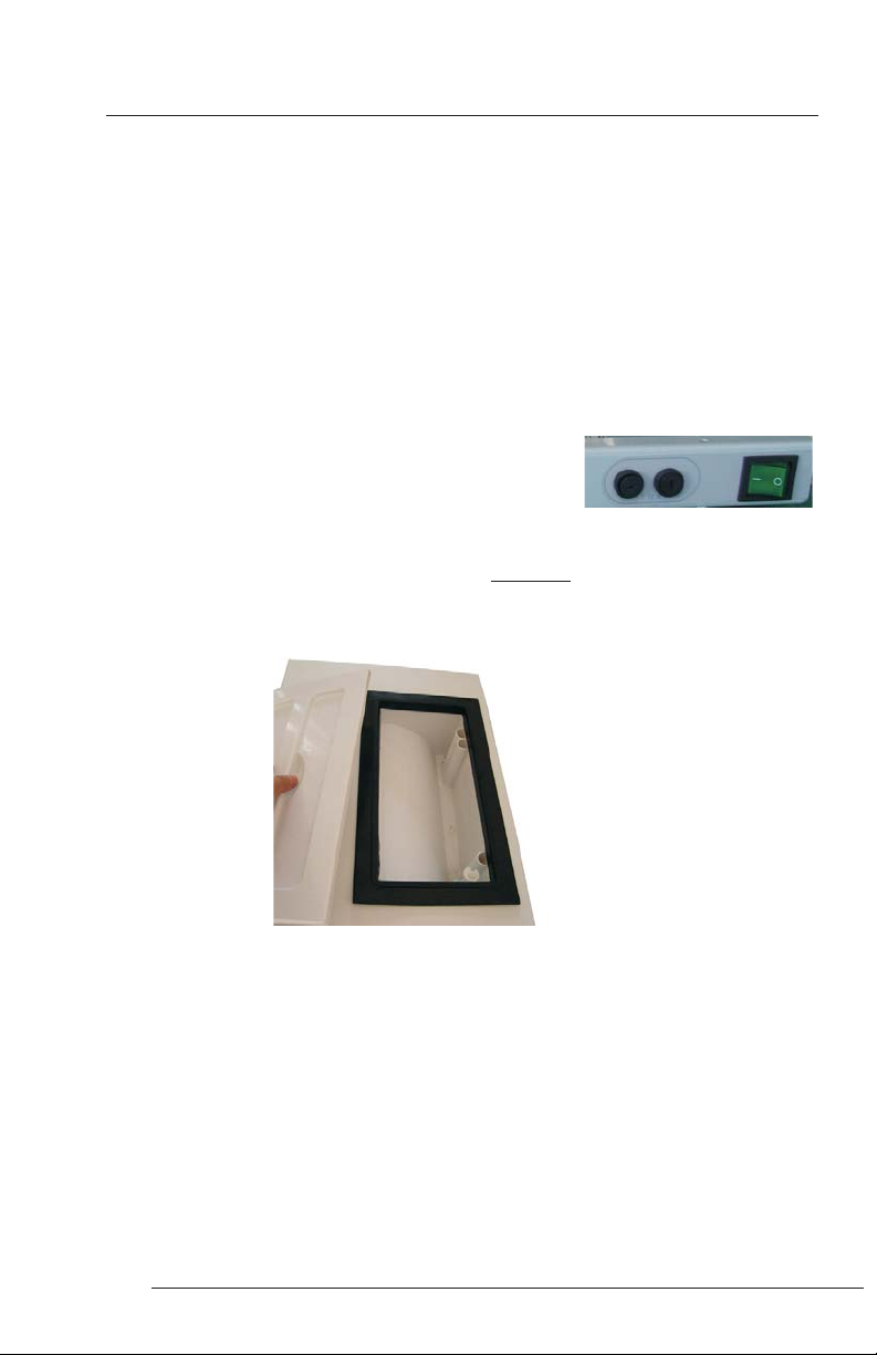
6.1.3 Power on - The switch is located underneath the control panel
on the front side of the machine.
Following power up, the control panel illuminates.
TheTime window will display “Ld” .
6.2 Filling the water tank
Open the top lid, and fill the tank with water. The water should
be filled within approximately 1 inch of the black seal. If you hear a beep
signal, the max water level is exceeded. Please stop filling immediately.
distilled
6.3 Sample Preperation
For the most effective sterilization and to preserve the sample, please
follow below:
*Arrange the samples of different material on different trays or with at least
2in. of space between them.
*Always insert a sterilization paper or cloth between the tray and sample,
to avoid direct contact between the different materials.
Instructions manual
6
Page 10

* Verify all samples are not sealed, capped or closed.
* Don't overload the trays above the stated limit (seeAppendix 1).
* Don't stack the trays one above the other or put them in direct contact with
the walls of the sterilization chamber.
* When handling the trays, always use the tray removal tool.
* Wrap each sample separately, if samples are wrapped together verify that
they are of the same material.
* Seal the wrap with sterilization adhesive ribbon or by a thermal sealer.
* Never seal with metallic clips, pins, etc. as this jeopardizes the maintenance
of the sterility;
* When using sterilization paper, set the plastic part downward (tray side)
and the paper side facing upward.
Always wrap samples.
6.4 Select the sterilization program
Select the appropriate sterilizationtemperature
and cycle. (For additionalinformation, see
appendix 2.)
6.5 Running the sterilization program
After selecting the appropriate sterilization
settings, load the samples onto the loading tray
and insert the tray into the autoclave using the
tray handling tool.
7
Instructions manual
Page 11

6.6 After the samples are loaded, close
and lock the door by turning the door
handle clockwise until it stops.
Caution: You must turn the door handle to the maximum position,
otherwise the machine will alarm and an error message will
be displayed during the cycle.
6.7 Starting the sterilization program.
Press the STARTbutton, the machine will begin
the sterilization cycle and complete all phases
(fill, sterilize, exhaust and dry) automatically.
The cycle will complete in 12-65 minutes.
(See )
Appendix 2
Caution: When you press the "Start" button and the door handle has not
been turned to the maximum position, “ will flash
on theTime display window. The cycle will not begin
until the door has been completely closed and the "Start"
button is pressed again.
do”
6.8 Sterilization cycle completion
After a cycle is completed the time display will show “Ed”
Once the pressure has reached 0 PSI on the display the door can be
opened and samples can be removed.
Always use the tray removal tool to load or unload the tray in
order to avoid touching the hot surface of the trays.
Instructions manual
8
Page 12

7. Draining the water tanks
1.
Connect the supplied drain hose to
the drain valve by pressing it on firmly.
2.
Set the drain valve to the open
position by turning it counter clockwise
3.Pull the drain valve outward, the
tank will begin to drain through the hose.
water, push the drain valve inward and
set to the closed position
The sterilizer includes two draining valves. The left valve is used
for draining the used water tank. The right valve is used for draining
the cleanwater tank. Always be sure that the hose is draining into
a vessel with at least 2L capacity.
4.After you have completed draining the
9
Instructions manual
Page 13

8 Advanced adjustment settings
8.1 Adjustment of sterilization time and drying time
8.1.1 Hold the UNWRAPPED button for 30seconds. The machine will beep
to signify that you have enetered the advanced settings mode.
8.1.2 The pressure display window shows“0” and the temperature display
window shows - - -. The timer display windowwill show the preprogrammes sterilization time parameter.
8.1.3 Select the sterilization program that you wish to adjust. For example,
If you want to adjust the parameter of Press the
WRAPPED
8.1.4 Press button, the value of time parameter will plus one.
8.1.5 After finishing the adjustment, press button to confirm it.
8.1.6 When adjusting the program, there is only one option,
2. This is to adjust the drying time.
Caution:Always ensure that the sample being sterilized can
withstand the sterilization time that is being programmed.
button. Press the button again ,the time display shows“1”.
0 means the 121 sterilization time.(The range from 3 to 40 min.)
1 means the 134 sterilization time.(The range from 3 to 40 min.)
2 means the drying time.(The range from 3 to 20 min.)
TEMP
DRYING
,
WRAPPED.
START
Instructions manual
10
Page 14

9. Printer (Optional)
9.1 If you have purchase the BioClave printer device, you can connect the
printer cable to the back of the sterilizer.
9.2 Connect the printer power cord to the socket with the proper electrical
specifications.
9.3 Power on the sterilizer and press the“sel” button.
9.4After the sterilization cycle has completed, the printer will begin printing
the details of the sterilization cycle (see below).
Example of the print report
¨¨¨¨¨¨¨¨¨¨¨¨
Program: wrapped
Temperature: 134
Pressure: 39 PSI
Vacuum Num.: 3
Dry Time: 15min
Ster Time: 12min
Cycle No: 00009
¨¨¨¨¨¨¨¨¨¨¨¨¨
MAX.Temp: 135.1
MIN. Temp: 134.1
AVG. Temp: 134.6
MAX. Pres.: 41PSI
MIN. Pres.: 38PSI
AVG. Pres.: 39 PSI
¨¨¨¨¨¨¨¨¨¨¨¨¨
Start Time: 22:38
End Time: 23:17
Date: 2008-07-19
¨¨¨¨¨¨¨¨¨¨¨¨
¡
11
Instructions manual
Page 15

10 Maintenance
7. Maintenance
Frequency
Daily
Weekly
Annually
Clean the door seal
Wipe dry the inner chamber
Clean the clean water reservoir
Clean the inner-chamber
Replace the door seal
Operation
8.1 Cleaning the door seal
Clean the door seal daily with a softy cloth saturated in
distilled water
8.2 Cleaning the clean water tank
Clean the clean water tank every
week with medical disinfectant .
Instructions manual
12
Page 16

10.3 Cleaning the inner-chamber, weekly
Remove the trays and tray rack from the inner-chamber
-
- Wipe the inner chamber with a soft cloth saturated in distilled water
-Apply the same procedure to the trays and tray rack.
10.4 Door adjustment
Below are the instructions for the door adjustment. This should only be
performed if the door is not providing the proper seal or if the door seal has
just been replaced.
10.4.1 Open the door and insert the door adjustment tool in the gap beneath the
plastic cover (Fig. 2).
10.4.2 To tighten the door seal, use this tool to adjust the door adjustment nut
counter clockwise (Fig. 1).
10.4.3 If the door seal is too tight (it is difficult to lock/unlock the door),
you may also adjust the door adjustment nut clockwise to loosen it.
Fig. 1
Caution:
Never attempt to adjust the door seal when the door is in the
closed position.
13
Fig. 2
Instructions manual
Page 17

10.5 Replacement of the door seal
10.5.1 Fully open the door.
10.5.2 Remove the door seal carefully by pulling it by hand away from
the door
10.5.3 Clean the new door seal carefully with a soft cloth saturated
with distilled water.
10.5.4 Moisten the new seal with medical disinfectant .
10.5.5 Insert the new seal following the instruction below:
1). Press on the top of the seal.
3). Press on the left and right
portions of the seal.
Caution:Always ensure the chamber and the door have
been cooled down before attempting to change the seal.
Instructions manual
2). Press on the bottom of the
seal.
4). Press the remaining seal surface
and ensure that it is smooth.
14
Page 18

10.6 Replace fuse
1). Switch off the power.
2). Push inward with a flat head
screw driver, then unscrew the fuse
counter clockwise).holder (
4).Replace the fuse with a fuse
of the proper electrical
requirements (see pg.2).
.
3). Pull out the fuse holder by
hand.
5). Place the fuse holder back in
place and use a flat head screw
driver to fully push it in. Then
tighten (clockwise).
11. Transport and Storage
11
.1 Switch off the sterilizer before transportation or storage. Pull out the plug
and let the machine cool down.
11.2 Drain both the clean and the used water tank.
11.3 Conditions for transportation and storage:
Temperature: -20 C /~ +55C
Relative humidity: 85%
Atmospheric pressure: 50kPa~106kPa
15
Instructions manual
Page 19

12. Error Codes
Code
E1
E2
E3
E4
E5
E6
E7
E8
E9
EE
Description Proposed solution
Steam generator temperature
sensor error
Inner temperature sensor error
Temperature sensor of chamber
wall error
Failure to raise temperature
Failure to release steam
Door has opened during the cycle
Time Error
Steam generator overheat
Failure to hold temperature
Program manually interrupted
Check steam generator temperature
sensor
Check inner temperature sensor
Check temperature sensor of chamber
wall
Check the water pump or the door seal
Check the air release valve
Make sure you have turned the door handle
to the max. position or check the door switch
Check the water pump and the
air release valve
Check steam generator temperature
sensor
Ensure that the clean water tank is not
empty or contactyourdealer to checkthe
heating system and temperature sensors.
Shut off the power and restart the
machine
Failure to initialize
EF
Instructions manual
Shut off the power and restart the
machine
16
Page 20

13. Service and Contact
For additional information on any of the error codes listed in section
10, please contact your sales representative, or contact Biomega
Research Products Service Department at 1-908-769-5555. Please
have the unit’s serial number (located on the back panel of the
instrument) available when calling. Do not send in a unit for service
without first calling to obtain a repair authorization number and a
decontamination form. The unit should be properly packed to avoid
damage.Any damage resulting from improper packing shall be the
responsibility of the user.
17
Instructions manual
Page 21

APPENDIX 1
Water Properties/Characteristics:
DESCRIPTION
Evaporate residue
Silicium oxide sio
Iron
Cadmium
Lead
Rest of heavy metals, excluding
iron, cadmium, lead
Chloride
Phosphates
Conductivity (at 20 )。
pH value
Appearance
Hardness
2
WATER
。10 mg/l
。1 mg/l
。0.2 mg/l
。0.005 mg/l
。0.05 mg/l
。0.1 mg/l
。2 mg/l
。0.5 mg/l
。ヲ15 s/cm
5-7.5
Colorless, clean,
without sediments
。0.02 mmol/l
CONDENSATE
。1.0 mg/kg
。0.1 mg/kg
。0.1 mg/kg
。0.05 mg/kg
。0.1 mg/kg
。0.1 mg/kg
。0.1 mg/l
。0.1 mg/l
。ヲ3s/cm
5-7
Colorless, clean,
without sediments
。0.02 mmol/l
Instructions manual
18
Page 22

APPENDIX 2
DIAGRAMS OFTHE STERILIZATION PROGRAMMES
PROGRAM
UNWRAPPED
WRAPPED
LIQUID
DRY ONLY
(°C)
Temperature
134
121
134
121
134
121
<100
(PSI)
Pressure
30
16
30
16
30
16
0
4
15
6
15
12
30
15
(min.)
Holding time
12~30
30~45
30~40
35~50
30~65
45~65
(min.)
Total time
TYPE
Unwrapped solid
material
Unwrapped hollow
material
Single-wrapped solid
material
Wrappedliquid
Wrappedliquid
The max. temperature of the 134 C sterilization cycle is 136C
The max. temperature of the 121 C sterilization cycle is 123C
(kg)
MAXLOAD
5.00
5.00
5.00
4.00
0.50
0.50
19
Instructions manual
Page 23

Pressure psi
30
15
0
30
UNWRAPPED
134°C
Time (min)
Pressure psi
UNWRAPPED
121°C
15
0
Instructions manual
Time (min)
20
Page 24

Pressure psi
30
15
0
30
WRAPPED
134°C
Time (min)
Pressure psi
WRAPPED
121°C
15
0
21
Time (min)
Instructions manual
Page 25

Pressure psi
30
15
0
30
15
LIQUID
134°C
Time (min)
Pressure psi
LIQUID
121°C
0
Instructions manual
Time (min)
22
Page 26

APPENDIX 3
ELECTRICAL DRAWING
TANK MAX. LEVEL
PUBLIC
TANK MIN. LEVEL
USED WATER TANK
MAX. LEVEL
DOOR SWITCH
KEYBOARD
DATA LINE
PRINTER
OUTPUT
TP 1
TP 2
TP 3
V4
T12A
20
T12A
20
¡ 220V
110
V1
PRESSURE SENSOR
Tp1: Steam generator temperature sensor
TP2: Inner-Chamber temperature sensor
TP3:Temperature sensor of chamber wall
V1:Air release valve
V4:Water release valve
¡ 21V
¡ 9V
THERMAL
PROTECTOR
THERMAL
PROTECTOR
AC220V
110
OUTPUT
FAN
WATE R
PUMP
STEAM
HEATER
CHAMBER
HEATER
23
Instructions manual
Page 27

APPENDIX 4
HYDRAULIC DRAWING
Safety valve
Pressure
sensor
Pump
Condenser
V1:Air release valve
V4:Water release valve
Chamber
Distilled water tank
Used water tank
Instructions manual
24
Page 28

 Loading...