

Page 1
User’s Manual
™
Non-Inva si ve Cardiac Output M onitor
Model 7300
February 1, 2001
Catalog No. 9226-23-05
5 Technology Drive, Wallingford, Connecticut, U.S.A. 06492. All rights reserved.
Copyright © 2001. Novametrix Medical Systems Inc.
Page 2

Page 3

Thank you …
Thank you for purchasing the NICO® Non-Invas ive Cardiac Output monitor from Novame tr i x .
®
NICO
measures cardiac output through respiratory gas analysis based on the well accepted
Fick Principle, providing continuous and accurate display of cardiac output. The monitor also
operates in Respiratory Mechanics-only mode, providing the clinician with a respiratory profile of
the patient through a combination of capnography, airway flow and pressure, and pulse
oximetry.
We expect that you will fi nd the application and u se o f NI C O
to adopt th is exciti n g tec hno log y in to your clin ic al p ractic e . NICO® can provide accurate cardiac
output values without the need for invasive procedures, benefitting the patient, the clinician,
and the health care system in general.
We appreciate your patro na ge and look forwar d to de velo p ing a long-term rela tionship with you
and your institution.
Sincerely,
®
extremely simple, making it easy
USA TOLL F REE 1-800-243-3444
PHONE 205-265-7701
FAX 205-284-0753
WORLD WIDE WEB:
http://www.novametrix.com
Customer Service
sales@novametrix.com
Technical Service
techline@novametrix.com
E-MAIL:
Rev. 05 NICO User’s Manual iii
Page 4

Introduction
About this manual This manua l is wr itten fo r clin ical pers onne l us ing t he No vametr ix NI CO
Output Monitor , Model 7300, and the sensors and accessories intended for use with the monitor .
This document contains information which is proprietary and the property of Novametrix Medical
Systems Inc., and may not be reproduced, stored in a retrieval system, translated, transcribed,
or transmitted, in any form, or by any means, without the prior explicit written permission of
Novametrix Medical Systems Inc. Novametrix reserves the right to change specifications without
notice.
NICO® Monitor Technical Description
Manufacturing Quality & Safety
Declaration of
Per requirements of IEC 601-1, the NICO® monitor is classified as class II equipment, internally
powere d, wit h typ e BF applie d pa rt, and an enc losur e prot ecti on rat ing o f IPX0 . The NIC O
monitor is Year 2000 compliant.
Transport/Storage: -10 to +55° C (14-131° F), 10-95% R.H. no n-condensing
Operating Conditions: 10 to +40° C (50 to 104° F), 10-90% R.H. non-condensing
The NICO
service personn el. A t echn ical Service Manual is availab le for use by technical personnel.
The Novametrix Medical Systems Inc. manufacturing facility is certified to both ISO 9001 and
EN46001 (MDD93/42/EEC Annex II). Novametrix’ products bear the “CE 0086” mark. The
product is certified by Underwriter’s Laboratories (UL) to bear the UL mark; and tested by TÜV
Rheinland to IEC 601-1/EN60 601-1.
The Autho r ized Repr es entative f or Novametr ix equipment is:
®
monitor, Model 7300, contains no use r serv iceab le parts. Refer servicing to qualified
Confor mity with
European Union
Directive
D.R.M. Green
European Compliance Services Limited,
Oakdene Hou s e,
Oak Road,
Watchfield
Swindon, Wilts SN6 8TD
United Ki ngdom
®
Non-Invasive Cardiac
®
Trademarks and Patents
Manual Revision History
CAPNOSTAT CO2 Sensor and NICO are regis ter ed tr ade mar ks (®); NICO2 and the stylized NICO
with CO2 shadow, NICO Sensor, NICO Loop and CObar (cardiac output confidence b ar),
SuperBright and Y-Sensor are trademarks (™) of Novametrix Medical Systems Inc. Other
trademarks and registe r ed tra d em arks are the pr o perty of their r espective own er s.
®
NICO
and its sensors and accessories are covered by the following USA patents: 4,859,858,
4,859,859, 4,914,720, 5,146,092, 5,153,436, 5,190,058, 5,206,511, 5,251,121, 5,347,843,
5,369,277, 5,379,650, 5,398,680, 5,535,633, 5,616,923, 5,693,944, 5,789,660, 5,793,044,
5,820,550, 5, 891,026 , 5, 999,834 , 6,098 ,62 2, 6,12 6,6 10, D42 4,19 3, 6,17 9,7 84. Oth er pate nts
pending.
11-Mar-99 Release at Rev. 00.
23-Mar-99 Revision 01.
05-Oct-99 Revision 02. R-N677
20-Mar-00 Revision 03. R-N741
19-Oct-00 Revision 04, R-N807
01-Feb-01 Revision 05, R-N850
iv NICO User’s Manual Rev. 05
2
Page 5

Table of Contents
Welcome to NICO
General Description . . . . . . . . . . . . . . . . . . . . . . . . . . . . . . . . . . . . . . . . . . . . . . . . . . . . . . 1
Front Panel . . . . . . . . . . . . . . . . . . . . . . . . . . . . . . . . . . . . . . . . . . . . . . . . . . . . . . . . . . . . . 1
Rear Panel . . . . . . . . . . . . . . . . . . . . . . . . . . . . . . . . . . . . . . . . . . . . . . . . . . . . . . . . . . . . . 2
Symbols . . . . . . . . . . . . . . . . . . . . . . . . . . . . . . . . . . . . . . . . . . . . . . . . . . . . . . . . . . . . . . . . 3
AC/Battery Operation . . . . . . . . . . . . . . . . . . . . . . . . . . . . . . . . . . . . . . . . . . . . . . . . . . . . 4
NICO® Parameter List . . . . . . . . . . . . . . . . . . . . . . . . . . . . . . . . . . . . . . . . . . . . . . . . . . . 5
Principles of Operation . . . . . . . . . . . . . . . . . . . . . . . . . . . . . . . . . . . . . . . . . . . . . . . . . . . 8
®
. . . . . . . . . . . . . . . . . . . . . . . . . . . . . . . . . . . . . . . . . . . . . . . . . . . . . 1
Navigating in Cardiac Output mode . . . . . . . . . . . . . . . . . . . . . . . . . . . . . . . . . . 10
Areas of the Display . . . . . . . . . . . . . . . . . . . . . . . . . . . . . . . . . . . . . . . . . . . . . . . . . . . . 10
Navigating the Display System . . . . . . . . . . . . . . . . . . . . . . . . . . . . . . . . . . . . . . . . . . . 10
KNOB selectable Monitoring Screens . . . . . . . . . . . . . . . . . . . . . . . . . . . . . . . . . . . . . 11
MENU key Screen Displays . . . . . . . . . . . . . . . . . . . . . . . . . . . . . . . . . . . . . . . . . . . . . . 13
DATA ENTRY key Screen Displays . . . . . . . . . . . . . . . . . . . . . . . . . . . . . . . . . . . . . . . 14
Navigating in Respiratory Mechanics mode . . . . . . . . . . . . . . . . . . . . . . . . . 16
Areas of the Display . . . . . . . . . . . . . . . . . . . . . . . . . . . . . . . . . . . . . . . . . . . . . . . . . . . . 16
Navigating the Display System . . . . . . . . . . . . . . . . . . . . . . . . . . . . . . . . . . . . . . . . . . . 16
KNOB selectable Monitoring Screens . . . . . . . . . . . . . . . . . . . . . . . . . . . . . . . . . . . . . 17
MENU key Screen Displays . . . . . . . . . . . . . . . . . . . . . . . . . . . . . . . . . . . . . . . . . . . . . . 18
DATA ENTRY key Screen Displays . . . . . . . . . . . . . . . . . . . . . . . . . . . . . . . . . . . . . . . 19
Safety . . . . . . . . . . . . . . . . . . . . . . . . . . . . . . . . . . . . . . . . . . . . . . . . . . . . . . . . . . . . . . . . . . . 21
Monitoring Cardiac Output . . . . . . . . . . . . . . . . . . . . . . . . . . . . . . . . . . . . . . . . . . . 24
Preparing for Use . . . . . . . . . . . . . . . . . . . . . . . . . . . . . . . . . . . . . . . . . . . . . . . . . . . . . . . 24
Begin NICO® monitoring . . . . . . . . . . . . . . . . . . . . . . . . . . . . . . . . . . . . . . . . . . . . . . . . 25
Entering Patient Data . . . . . . . . . . . . . . . . . . . . . . . . . . . . . . . . . . . . . . . . . . . . . . . . . . . 28
Entering ABG Data . . . . . . . . . . . . . . . . . . . . . . . . . . . . . . . . . . . . . . . . . . . . . . . . . . . . . 29
C.O. Averaging . . . . . . . . . . . . . . . . . . . . . . . . . . . . . . . . . . . . . . . . . . . . . . . . . . . . . . . . . 31
Respiratory Monitoring . . . . . . . . . . . . . . . . . . . . . . . . . . . . . . . . . . . . . . . . . . . . . . . 32
Preparing for Use . . . . . . . . . . . . . . . . . . . . . . . . . . . . . . . . . . . . . . . . . . . . . . . . . . . . . . . 32
Begin Respiratory Monitoring . . . . . . . . . . . . . . . . . . . . . . . . . . . . . . . . . . . . . . . . . . . . 34
Entering Patient Data . . . . . . . . . . . . . . . . . . . . . . . . . . . . . . . . . . . . . . . . . . . . . . . . . . . 34
Entering ABG Data . . . . . . . . . . . . . . . . . . . . . . . . . . . . . . . . . . . . . . . . . . . . . . . . . . . . . 36
Monitoring and Setup Screens . . . . . . . . . . . . . . . . . . . . . . . . . . . . . . . . . . . . . . . 39
Cardiac Output mode . . . . . . . . . . . . . . . . . . . . . . . . . . . . . . . . . . . . . . . . . . . . . . . . . . . 39
Respiratory Screens (Optional) . . . . . . . . . . . . . . . . . . . . . . . . . . . . . . . . . . . . . . . . . . . 41
Respiratory Mechanics mode . . . . . . . . . . . . . . . . . . . . . . . . . . . . . . . . . . . . . . . . . . . . 46
Rev. 05 NICO User’s Manual v
Page 6

Notes on Patien t Mo nitoring . . . . . . . . . . . . . . . . . . . . . . . . . . . . . . . . . . . . . . . . . . 53
Automatic Purging . . . . . . . . . . . . . . . . . . . . . . . . . . . . . . . . . . . . . . . . . . . . . . . . . . . . . . 53
Manual Purging . . . . . . . . . . . . . . . . . . . . . . . . . . . . . . . . . . . . . . . . . . . . . . . . . . . . . . . . 53
Intra-Aortic Balloon Pump . . . . . . . . . . . . . . . . . . . . . . . . . . . . . . . . . . . . . . . . . . . . . . . 54
Configuration Menu . . . . . . . . . . . . . . . . . . . . . . . . . . . . . . . . . . . . . . . . . . . . . . . . . . . . . 55
Reference Handbooks . . . . . . . . . . . . . . . . . . . . . . . . . . . . . . . . . . . . . . . . . . . . . . . . . . 55
Alerts . . . . . . . . . . . . . . . . . . . . . . . . . . . . . . . . . . . . . . . . . . . . . . . . . . . . . . . . . . . . . . . . . . . 56
NICO® Alert Priorities . . . . . . . . . . . . . . . . . . . . . . . . . . . . . . . . . . . . . . . . . . . . . . . . . . . 56
Responding to Alert Audio . . . . . . . . . . . . . . . . . . . . . . . . . . . . . . . . . . . . . . . . . . . . . . . 56
Parameter Limit Alerts . . . . . . . . . . . . . . . . . . . . . . . . . . . . . . . . . . . . . . . . . . . . . . . . . . 57
No Respiration Alert . . . . . . . . . . . . . . . . . . . . . . . . . . . . . . . . . . . . . . . . . . . . . . . . . . . . 58
NICO Sensor™ . . . . . . . . . . . . . . . . . . . . . . . . . . . . . . . . . . . . . . . . . . . . . . . . . . . . . . . . . 59
Disposable NICO Sensors™ . . . . . . . . . . . . . . . . . . . . . . . . . . . . . . . . . . . . . . . . . . . . . 59
CO2/Flow Sensors . . . . . . . . . . . . . . . . . . . . . . . . . . . . . . . . . . . . . . . . . . . . . . . . . . . . . 62
Choosing a CO2/Flow Sensor . . . . . . . . . . . . . . . . . . . . . . . . . . . . . . . . . . . . . . . . . . . . 63
Connecting a CO2/Flow Sensor . . . . . . . . . . . . . . . . . . . . . . . . . . . . . . . . . . . . . . . . . . 63
CAPNOSTAT® CO2 Sensor . . . . . . . . . . . . . . . . . . . . . . . . . . . . . . . . . . . . . . . . . . . 65
The CAPNOSTAT® CO2 Sensor . . . . . . . . . . . . . . . . . . . . . . . . . . . . . . . . . . . . . . . . . 65
CAPNOSTAT® Adapter Zero . . . . . . . . . . . . . . . . . . . . . . . . . . . . . . . . . . . . . . . . . . . . . 66
Pulse Oximetry Sensors . . . . . . . . . . . . . . . . . . . . . . . . . . . . . . . . . . . . . . . . . . . . . . 67
Oximetry Sensors . . . . . . . . . . . . . . . . . . . . . . . . . . . . . . . . . . . . . . . . . . . . . . . . . . . . . . 67
Finger Sensor . . . . . . . . . . . . . . . . . . . . . . . . . . . . . . . . . . . . . . . . . . . . . . . . . . . . . . . . . . 68
Y-Sensor™ . . . . . . . . . . . . . . . . . . . . . . . . . . . . . . . . . . . . . . . . . . . . . . . . . . . . . . . . . . . . 68
Single Patient Use Sensors . . . . . . . . . . . . . . . . . . . . . . . . . . . . . . . . . . . . . . . . . . . . . . 71
Messages . . . . . . . . . . . . . . . . . . . . . . . . . . . . . . . . . . . . . . . . . . . . . . . . . . . . . . . . . . . . . . 73
Message Areas - Cardiac Output mode . . . . . . . . . . . . . . . . . . . . . . . . . . . . . . . . . . . 73
Message Areas - Respiratory Mechanics mode . . . . . . . . . . . . . . . . . . . . . . . . . . . . . 78
External Devices . . . . . . . . . . . . . . . . . . . . . . . . . . . . . . . . . . . . . . . . . . . . . . . . . . . . . . . 82
GE Medical Systems Solar® Interface . . . . . . . . . . . . . . . . . . . . . . . . . . . . . . . . . . . . . 82
Agilent Technologies VueLink Interface . . . . . . . . . . . . . . . . . . . . . . . . . . . . . . . . . . . 83
ASCII Output . . . . . . . . . . . . . . . . . . . . . . . . . . . . . . . . . . . . . . . . . . . . . . . . . . . . . . . . . . 85
Analog Output . . . . . . . . . . . . . . . . . . . . . . . . . . . . . . . . . . . . . . . . . . . . . . . . . . . . . . . . . 86
Alerts and Messages . . . . . . . . . . . . . . . . . . . . . . . . . . . . . . . . . . . . . . . . . . . . . . . . . . . . 87
Maintenance . . . . . . . . . . . . . . . . . . . . . . . . . . . . . . . . . . . . . . . . . . . . . . . . . . . . . . . . . . . 88
Cleaning and Sterilization . . . . . . . . . . . . . . . . . . . . . . . . . . . . . . . . . . . . . . . . . . . . . . . . 88
Monitor Maintenance Schedules . . . . . . . . . . . . . . . . . . . . . . . . . . . . . . . . . . . . . . . . . . 89
Battery Maintenance . . . . . . . . . . . . . . . . . . . . . . . . . . . . . . . . . . . . . . . . . . . . . . . . . . . . 89
Specifications . . . . . . . . . . . . . . . . . . . . . . . . . . . . . . . . . . . . . . . . . . . . . . . . . . . . . . . . . . 90
NICO® Accessories . . . . . . . . . . . . . . . . . . . . . . . . . . . . . . . . . . . . . . . . . . . . . . . . . . . . 92
Warranty . . . . . . . . . . . . . . . . . . . . . . . . . . . . . . . . . . . . . . . . . . . . . . . . . . . . . . . . . . . . . . . 94
vi NICO User’s Manual Rev. 05
Page 7
General Descriptio n
Welcome to NICO
General D escription
NICO®, a Non-Invasive Cardiac Output monitor from Novametrix Medical Systems Inc., noninvasively m ea sures an d d isp lays card ia c out put (C .O.). Th e NI C O
displays cardiac index and stroke volume, as well as various respiratory monitoring parameters
including CO
mode, NICO® can be used as a respiratory profile monitor, without cardiac output displayed. In
either mod e, NIC O
efficien t pa tient man ag ement.
Indications The NI CO
Output mode, t he m onitor is use d for t he m onito ring of cardi ac out put a nd various resp iratory
parameters of adult patients receiving mechanical ventilation. In Respiratory Mechanics mode,
the NICO
neonatal patients. NICO® is not intended for any other purpose.
Contraindications In Cardiac Output mode, use of the NICO
small rise (3-5 mmHg, 0.4-0.67 kPa) in their PaCO2 level cannot be tolerated.
Front Panel
elimination (VC O2) and alveolar minute ventilation. In Respiratory Mechanics
2
®
provide s the clinic ian wi th im porta nt inf ormat ion t o aid in pre cise and
®
monitor is in dicat ed for use b y techn ically sk illed cli nical pe rsonnel . In Cardi ac
®
monitor is used for monitoring the respiratory parameters of adult, pediatric and
®
®
monitor, Model 7300, also
®
monitor is contraindicated in patients in whom a
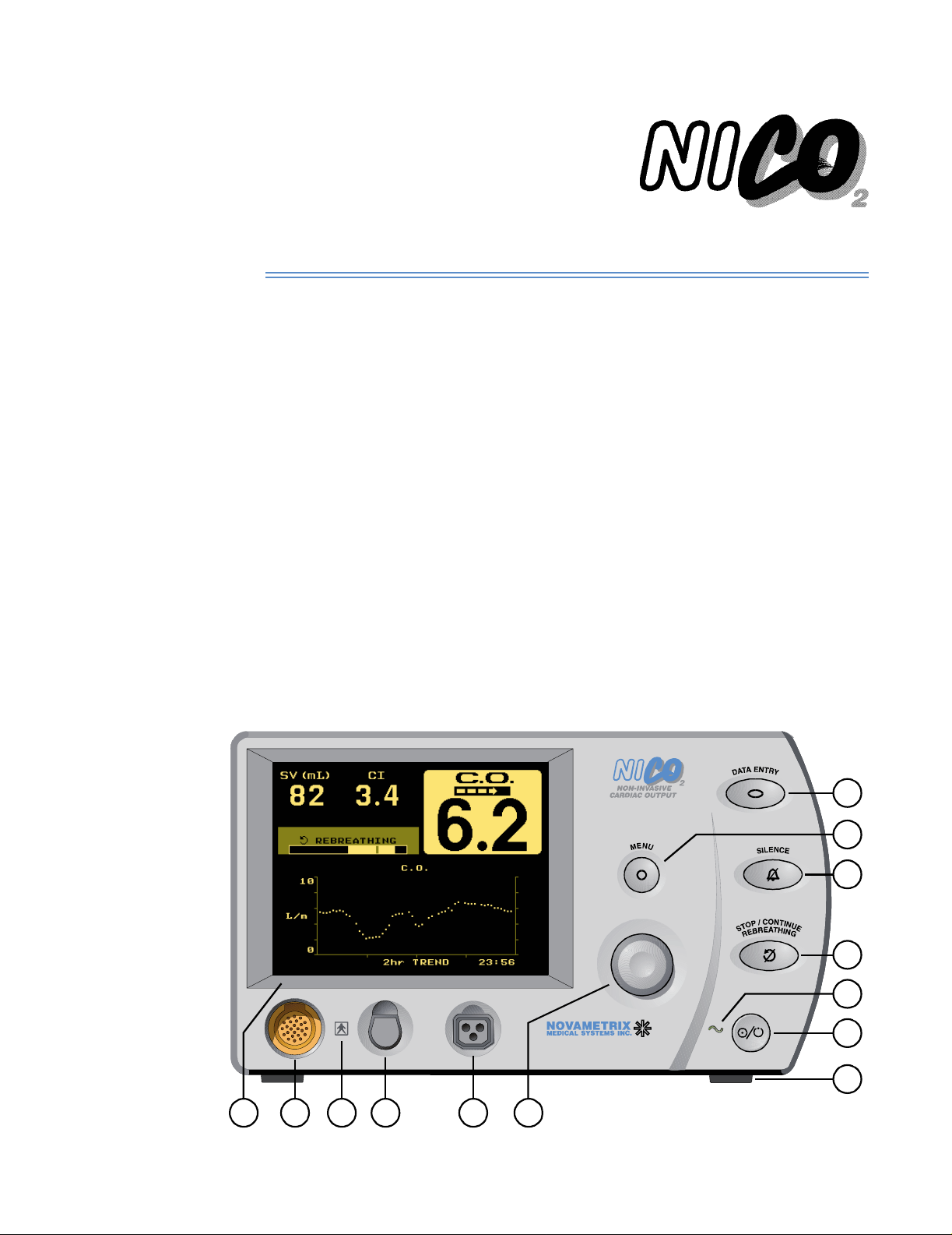
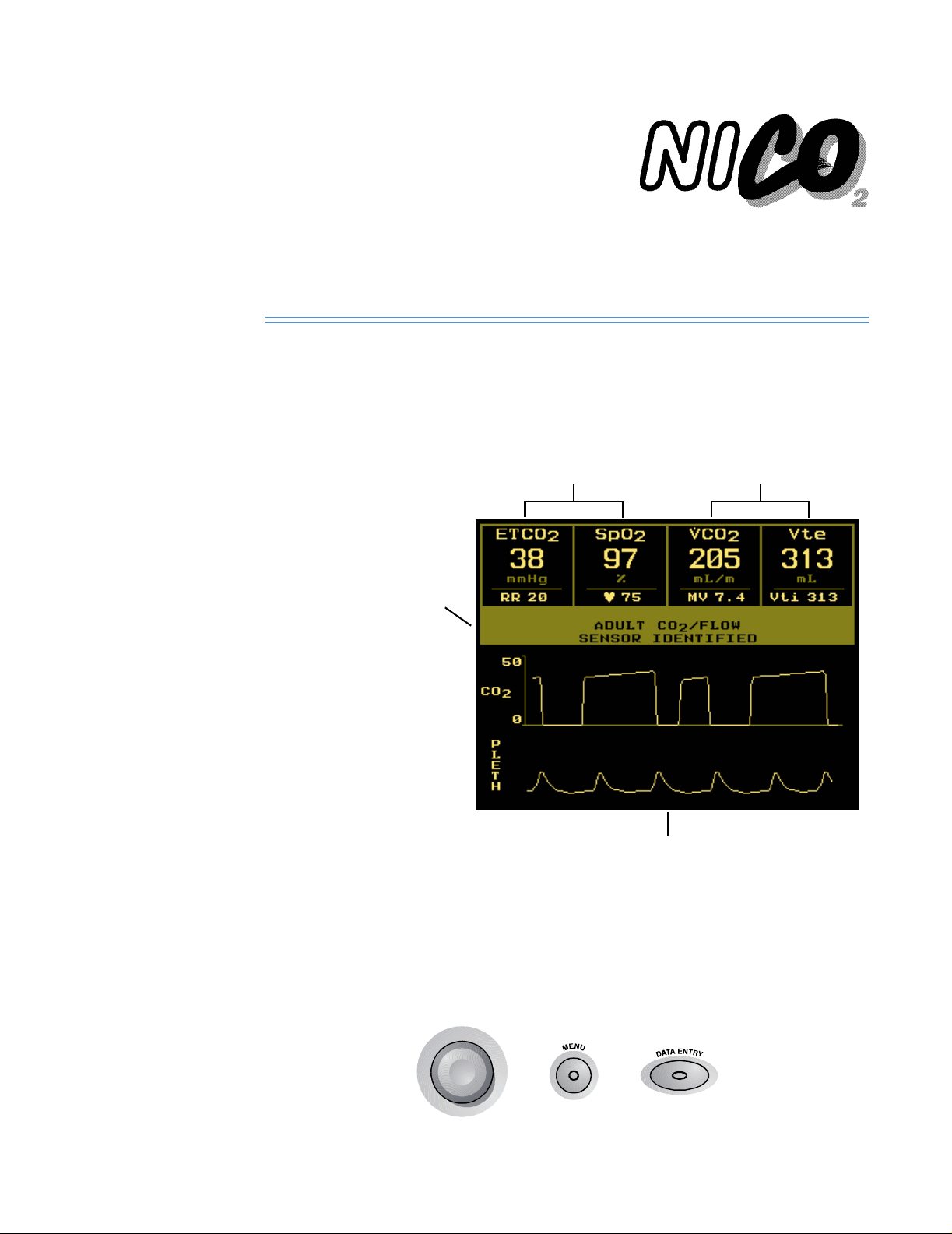
The NICO® monitor ’s front pane l includ es a di splay sc reen, se nsor inp ut conn ector s, a cont rol
knob, and operational push button keys and indicators that are explained below.
7
8
9
10
11
12
13
54321 6
Rev. 05 NICO User’s Manual 1
Page 8

Rear Panel
1 Display Screen. The screen displays NICO
waveforms and messages, along with setup and configuration data.
2 CAPNOSTAT
CO
Sensor, Catalog Number 9567-00 here.
2
®
CO2 Sensor Inpu t C o nnec to r. Connect only a Novametrix CAPNOSTAT®
®
data, respiratory mechanics, trends,
3 Connector Isolation Icon. Identifies t h e connector to either side of this icon as a type
BF patient isolation connection.
4 Pulse Oximetry Sensor Input Connector. Connect only Novametrix pulse oximetry
sensors and extension cables approved for use with the NICO
®
monitor.
5 NICO Sensor™ Input Connector. Connect only Novametrix NICO Sensors™, Catalog
Number 8950-00, 8951-00 a nd 89 52-00 or Novametrix CO
Number 9765-00, 9766-00 a nd 97 67-00.
/Flow sensors, Catalog
2
6 KNOB. The KNOB is used to select monitoring screens, scroll through menus and to
change or enter values. The KNOB is generally turned to access different monitoring
screens and to highlight menu options, and pressed to accept or change those selections.
7 DATA ENTRY key. Press to activ ate the DATA ENTRY screen and illuminate the key’s green
icon. Press th e key again to return t o th e p r evio usly displayed s cr een. From the
DATA ENTRY screen, you can enter patient information including height, weight and
respiratory gas mixture, and access the ABG DATA ENTRY screen.
8 MENU key. Press to activate the SELECT A SCREEN menu and illuminate the key’s green
icon. Press th e key again to return t o th e p r evio usly displayed s cr een. From the
SELECT A SCREEN menu you can, by turning the knob, highlight the screen you wish to
display. Press the MENU key or the KNOB to display that selected screen .
9 SILENCE key. The SILENCE key is used to mute/prevent audible alerts. It also visua lly
indicates the presence of a “High Priorit y Alert”. The Silence feat u r e ope rate s in two
modes; a temporary “2 Minute Silence” mode and an “Audio Disabled” mode.
• 2 Minute Silence — Press and release to activate or deactivate the two minute silence.
The key’s icon illuminates amber when active and audible alerts will be muted for two
minutes, after which the icon turns off and any audible alert will sound.
• Audio Disabled — Press and hold for one second to prevent or allow any audible alerts.
The key’s icon illumin a t es a nd f las h es a mb er to ind icate that all audible alerts are
being suppressed.
• High Priority Alerts — (See “NICO® Aler t Prio r it ies” on page 56) The SILENCE key’s
icon illuminates and fla shes red to indicate High Prior it y Alert is active. The icon
alternately flashes red and amber if the audio is disabled and a High Priority Alert is
active.
10 STOP/CONTINUE REBREATHING key. Press to start NICO
automatic rebrea thi n g pr ocess. Subsequent presses will stop (amber indicato r
illuminated) or continue (amber indicator off) the rebreathing process. Press and hold for
two seconds to reset the NICO
cleared. The STOP/CONTINUE REBREATHING key will be amber and ina c t ive in
Respiratory Mechanics mode.
®
algorithm; the C.O. value and averaging filter will b e
®
monitoring and the
11 AC Mains Power Indicator. This ico n illuminates green to indicate AC Ma ins power is
applied to the mon it o r. To illum inate the icon, the m on it o r must be plugged into t he AC
outlet and the monitor’s rear panel power switch must be on (“|”).
12 OPERATE/STANDBY key. Press this key to turn the monitor on. If connected to the AC
outlet, the mon itor uses AC power, o t h erwise it powers up us ing its internal bat te r y
(provided the battery is cha r ged). Pres s th e OPERATE/STANDBY key aga in to put the
monitor into Standby mode (if using AC power) or to turn it off (if using battery power).
13 Kickstand (front and rear). The NICO
from above or below by extending the kickstand at the front or rear of the monitor.
®
monitor c an be positioned for better view ing
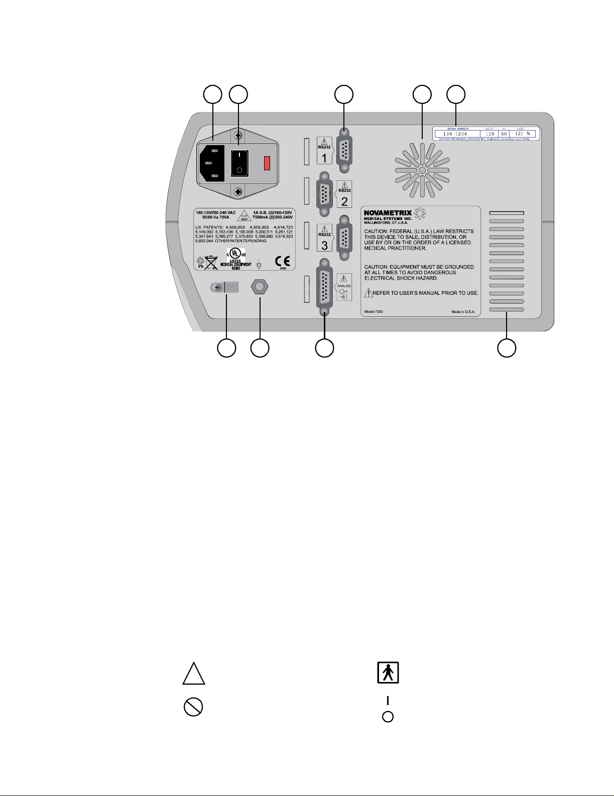
Rear Panel
The NICO® monitor’s rea r panel inc ludes an AC Mai ns pow er input mo dule , three R S232 ser ial
communications ports, an analog inpu t/outp ut port, equip otenti al connector, fan and ventilation
slots, and th e monitor ’s seri a l nu m b er label. These ar e explained belo w.
2 NICO User’s Manual Rev. 05
Page 9
Symbols
14 16 17 18
15
2019 21
22
14 AC Mains Power Cord Connection. Connect only approved hospital-grade line cords to
this connector.
15 AC Mains Power Switch. This switch controls the flow of AC current into the NICO
monitor. Press the “|” portion of the switch to supply the monitor with AC power, or the
“O” portion of the switch to interrupt the flow of AC power. If supplied with AC power, the
monitor illuminates the front panel AC Mains Power Indicator, energizes the fan and
recharges the internal battery.
®
16 RS232 Communications Ports. Three 9-pin serial communications ports provide for
digital communications with the NICO® monitor. (See “RS232 Communications” ).
17 Fan. The fan draws air in through the monitor. Do not block the fan’s air intake slots.
18 Serial Number Label. The N ICO
servicing to qualifie d p erso nnel.
®
monitor’s serial number is shown here. Refer
19 Power cord retaining clip. If desired, remove the screw, slip the cord through the clip
and insert and tighten the screw. Use only the supplied screw to secure the clip.
20 Equipotentiality. Connection to the monitor’s chassis (earth ground system).
21 Analog Input/ O ut put Por t. This 15-pin connector provides analog signal output
capability for the NICO® monitor (Input reserved for future use).
22 Ventilation Slots. Do no t block the air v en tilation slots.
Symbols
These sy mbols may be found o n the NICO® monitor, its sensors, accessories and
documentation.
Attention
Consult manual for detailed
!
information.
Single Patient Use
Treat in accordance with protocol
2
for “single patient use” items.
Patient Isolatio n
Identifies the patient iso la tio n
connection as type BF.
AC Mains Power Switch
“|” ON-connectio n to m a ins;
“O” OFF-disconnection from mains
Rev. 05 NICO User’s Manual 3
Page 10
AC/Battery Opera tion
Mains Fuse Rating
Mains rating for replacement fuses
250V
Separate colle ction
Take appropriate steps to ensure
that spent batteries ar e collected
separately when disposed of. This
symbol is found on the internal
battery and the monitor enclosure.
Recyclable item
This symbol is found on the internal
battery an d the monitor en clo sure.
AC/Battery Operation
The NICO® monitor is designed to be operated from AC Mains power. An internal battery
provides uninterrupted monitoring and trending capability for short periods (no more than 45
minutes) if the AC power is removed.
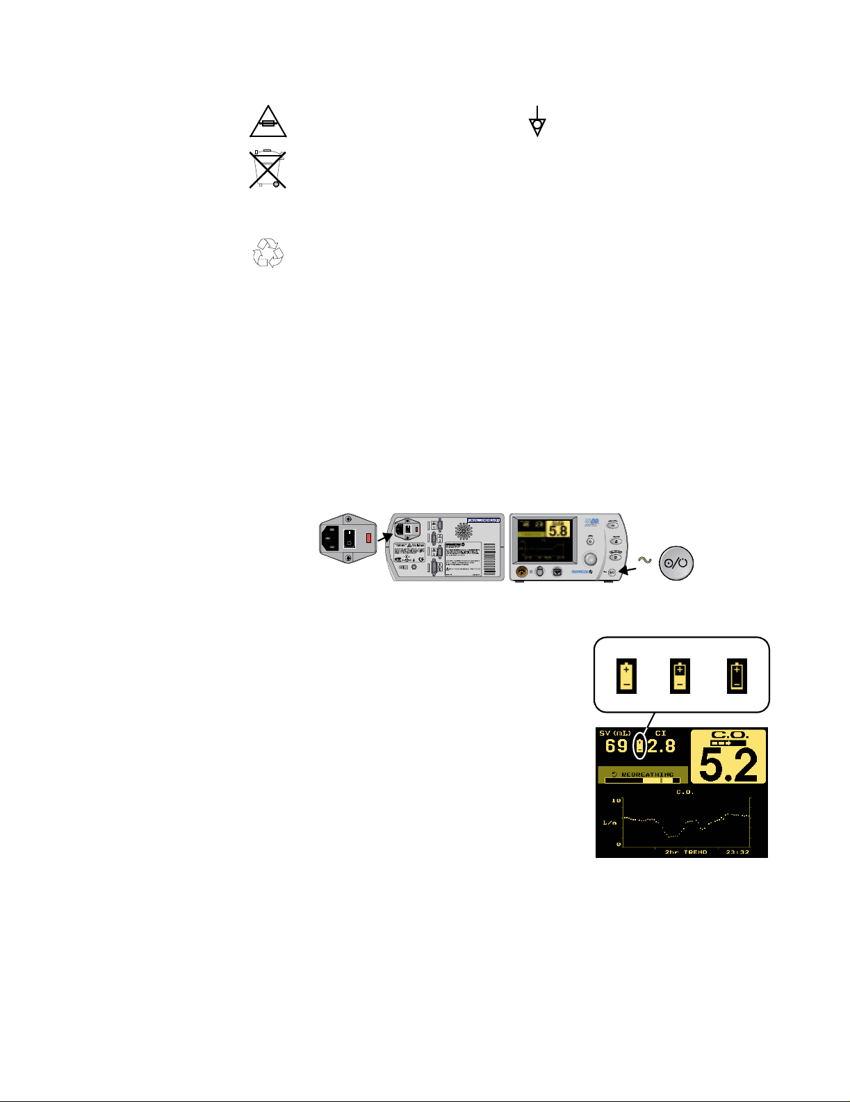
AC Mains Operation To ope ra te NICO
1 Plug the line cord into the r ear pan e l co n nect o r and the AC Mains power outlet.
2 Set the rear panel power switch to the On “|” position.
• The front panel AC Mains Power indicator illuminates.
• The monitor’s fan turns on.
• The inte r n al battery s tarts to rec h arge.
®
from AC Mains power:
Pb
Equipotentiality
Connection to monitor’s chassis.
Heavy Metal Content
Indicates heavy metal content,
specifically le ad. This symbol is
found on the internal battery and
the moni to r enc losure.
3 Press the front panel Operate/Standby key to tu r n th e m o n itor on and of f.
Battery Operation The NICO
from AC Ma ins powe r if the AC sou rce is r emoved. A fu lly
charged battery will power the moni tor fo r up t o 45 minutes.
While on battery pow er, NICO
“drains” as power is consume d .
The battery icon starts to flash when approximately 5
minutes of battery power remain. An audible alert tone also
sounds.
Reconnect to AC Mains power or the monitor will
automati ca lly shut o ff. A deplet ed ba tt ery may re quire 12 -16
hours to fully recharge.
To ope ra te NICO
1 Unplug the line cord or set the rear panel power switch
to the Off “O ” p o s ition.
2 Press the front panel Operate/Standby key to tu r n th e m o n itor on and of f.
®
monitor automatically switches to battery power
®
displays a battery icon that
®
on battery power:
• The front panel AC Mains Power indicator turns off.
Operate
/Standby
Battery icon shows capacity
full half depleted
4 NICO User’s Manual Rev. 05
Page 11

NICO® Parameter List
NICO® Paramet er List
Cardiac Output mode The NICO
®
monitor displays the parameters described in thi s tabl e.
Label Parameter Range/Units Description Screen Display
C.O. Cardiac Output 0.5-19.9 L/min Volume of blood pumped by the
All
heart each minute
CO-a Average Cardiac Output 0.5-19.9 L/min C.O. averaged value, displayed
when the fast-mode cardiac output
mode is chosen for la r ge dis pla y.
CO-f Fast-mode Cardiac
Output
0.5-19.9 L/min C.O. unaveraged value, displayed
when the aver age cardiac output
mode is chosen for la r ge dis pla y.
Cdyn Dynamic Compliance 0-500 ml/cmH
O Volume the lungs expand for a
2
given pressure
Last Completed Cycle
rebreathi n g cur ve &
Tabular Data
Last Completed Cycle
rebreathi n g cur ve &
Tabular Data
Numerics & Tabular
Data
Note that if the ventilator is set for
an inspiratory paus e th at is
detected by NICO, Cdyn becomes
Cstat.
CI Cardiac Index 0-9.9 L/min/m
ETCO
End Tidal Carbon
2
Dioxide
0-150 mmHg
0-20.0 %
0-20.0 kPa
Insp CO
Inspired Carbon Dioxide 3-50 mmHg
2
0.4-6.7 %
0.4-6.7 kPa
2
C.O. divided by body surface area All
Maximum CO2 plateau value at t he
end of the breath (r eflects al v eolar
CO
)
2
Maximum CO2 value observed
during the baseline portion of the
Inspiratory phase of the breath
Numerics, Respiratory
Numerics, CO
SBCO
rebreathi n g cur ves
General Message Area
(if above 3 mmHg for
10 sec (0.4 % or kPa))
, T abular Data &
2
(baseline shift above zero point)
MAP Mean Airway Pressure 0-100 cmH
MV Minute Volume 2-40 L/min Adult Volume (in liters) of gas delivered
O Mean (average) pressure in the
2
airway throughout the breath
to the patient per minute
Numerics & Tabular
Data
Numerics, Respiratory
Numerics & Tabular
Data
MV alv Alveolar Minut e Volume 0.05-16 L/min MV less deadspace (wasted)
ventilation
Numerics, Respiratory
Numerics & Tabular
Data
PCBF Pulmonary Capillary
Blood Flow
0.5-19.9 L/min Portion of the cardiac output that is
effecti v e in gas exchang e
3 min Cycle in
Progress rebreathing
curve & Tabular Data
/
PeCO
FeCO
Mixed expir e d CO2 0-100 mmHg,
2
2
PEEP Positive End Expiratory
Pressure
0-13.2 kPa or %
0-99 cmH
O Pressure in th e lu ngs at the end of
2
Volume weighted average CO2 in
the breath
expiration
Respiratory Numerics
& Tabular Data
Numerics, Flow/
Pressure & Tabular
Data
PEF Peak Expiratory Flow 2-180 L/min Highest absolute flow rate during
Tabular Data
expiration
PIF Peak Inspiratory Flow 2-180 L/min Highest absolute flow rate during
Tabular Data
inspiration
PIP Peak Inspiratory
Pressure
0-120 cmH
O Peak (highest) pressure in the
2
airway during inspiration
Numerics, Flow/
Pressure & Tabular
Data
/SpO2,
2
Rev. 05 NICO User’s Manual 5
Page 12

NICO® Parameter List
Label Parameter Range/Units Description Screen Display
Pulse Rate 30-250 bpm Number o f pulse beats per minu te Numerics, CO
/SpO2 &
2
Tabular Data
Raw Airway Resistance 0-1 00 cmH
O/L/sec Pressure required to cause gas
2
flow at a given rate
RR Respiration Rate 2-120 br/min Number of breaths per minut e Numerics, CO
Numerics & Tabular
Data
/SpO2 &
2
Tabular Data
RSBI Rapid Shallow
Breathing Index
0-1000 br/min/L Respiratory rate divided by
average spontaneous tidal volume
Respiratory Numerics
& Tabular Data
(only calculated when RR < 57)
SpO
Oxygen Saturation 0-100 % Oxyhemoglobin as a percentage of
2
total hemoglobin less dysfunctional
hemoglobin
SV Stroke Volume 0-250 ml Volume of blood pumped by the
Numerics, CO
Tabular Data &
/SpO2,
2
rebreathi n g cur ves
All
heart each beat
SVI S troke Volume Index 0-125 ml Stroke volume divided by body
Tabular Data
surface area
SVR Systemic Vascular
Resistance
0-5000 dynes sec/
5
cm
Resistance exerted by the blood
vessels on blood flow and is an
SVR Calculation &
Tabular Data
indicator of left ventricular
afterload.
SVRI Systemic Vascular
Resistance Index
2
Carbon Dioxide
Elimination
VCO
0-5000 dynes sec/
5
cm
SVR normalized to body surface
area
0-3000 ml/min Volume of CO2 eliminated through
the breath each minute
Tabular Data
Numerics, Respiratory
Numerics, SBCO
Tabular Data &
rebreathi n g cur ves
Vd Aw Airway deadspace 0-500 ml Includes added mechanical
deadspace proximal to the flow
Respiratory Numerics,
, Tabular Data
SBCO
2
sensor
Vd/Vt Deadspace to tidal
0-1.00 ml (PaCO
-PeCO2)/PaCO
2
2
volume ratio
Vd alv Alveolar deadspace 0-500 ml Difference between physiologic and
airway deadspace
Vt alv Alveolar tidal volume 0-2400 ml Tidal volume less airway
deadspace
Respiratory Numerics
& ABG Data E n tr y
Respiratory Numerics
& ABG Data E n tr y
Respiratory Numerics,
& Tabular Data
SBCO
2
Vte Expired Tidal Volume 200-3000 ml Volume of ga s exha le d p er bre a th Respiratory Num eri cs,
Flow/Pres sure &
SBCO
2
Vte-m Expired Ti da l Volume -
mechanical
Vte-s Expired Tidal Volume -
spontaneous
200-3000 ml Volume of mechanically exhaled
gas, per breath
200-3000 ml Volume of spontaneously exhaled
gas, per breath
Tabular Data
Tabular Data
Vti Inspired Tidal Volume 200-3000 ml Volume of gas inh al ed per breath Respiratory Numerics ,
Flow/Pres sure &
SBCO
2
Vti-m Inspired Tidal Volu m e -
mechanical
Vti-s Inspired Tidal Volume -
spontaneous
200-3000 ml Volume of mechanically inhaled
gas, per breath
200-3000 ml Volume of spontaneously inhaled
gas, per breath
Tabular Data
Tabular Data
2,
6 NICO User’s Manual Rev. 05
Page 13

NICO® Parameter List
Respiratory
The NICO® monitor displays the parameters described in thi s tabl e.
Mechanics mode
Label Parameter Range/Units Description Screen Display
Cdyn Dy nam ic Compliance 0-500 ml/cmH
ETCO
End Tidal Carbon
2
Dioxide
0-150 mmHg
0-20.0 %
0-20.0 kPa
I:E I:E Ratio 1:9.9 or 4:1 Ratio of inspiratory time (ti) to
MAP Mean Airway Pressure 0-100 cmH
MV Minute Volume 0.4-40 L/min adult
0.06-30 L/min pedi.
0.01-5 L/min neo na t al
MV alv Alveolar Minute Volume 0-16 L/min adult
0-8 L/min pediat r ic
0-4 L/min neonatal
NIP Negative Insp iratory
0 to -120 cmH
Pressure
/
PeCO
FeCO
PEEP Positive End Expiratory
Mixed expir e d CO2 0-100 mmHg,
2
2
0-13.2 kPa or %
0-99 cmH
Pressure
PEF Peak Expiratory Flow 2-180 L/min adult
0.5-100 L/min pedi.
0.25-25 L/min neo.
PIF Peak Inspiratory Flow 2-180 L/ min adult
0.5-100 L/min pedi.
0.25-25 L/min neo.
PIP Peak Inspiratory
0-120 cmH2O Peak (highest) pressure in the
Pressure
Pulse Rate 30-250 bpm Num ber o f pulse bea ts per minute All
Raw Airway Resistance 0-1 00 cmH
adult/pediatric
O Volume the lungs expand for a
2
given pressure
Maximum CO2 plateau value at t he
end of the breath (r eflects al v eolar
CO
)
2
expiratory time (te)
O Mean (average) pressure in the
2
airway throughout the breath
Volume (in liters) of gas delive r ed
to the patient per minute
MV les s deadspace (wasted )
ventilation
O Maximum negative pr essure during
2
inspiratory cycle
Volume weighted average CO2 in
the breath
O Pressure in th e lu ngs at the end of
2
expiration
Highest absol u te flow rate during
expiration
Highest absol u te flow rate during
inspiration
airway during inspiration
O/L/sec
2
Pressure required to cause gas
flow at a given rate
Numerics & Tabular
Data
All
Flow/Pressure
Numerics & Tabular
Data
All except Flow/
Pressure & Loops
Numerics & Tabular
Data
Loops
Numerics, SBCO2 &
Tabular Data
Numerics, Flow/
Pressure & Tabular
Data
Loops & Tabular Data
Loops & Tabular Data
Numerics, Flow/
Pressure & Tabular
Data
Numerics & Tabular
Data
0-500 cmH
neonatal
RR Respiration Rate 2-120 br/min adult
O/L/sec
2
Number of breaths per minute All
2-150 br / min pedi .
10-150 br/min neo.
RSBI Rapid Shallow
Breathing Index
0-1000 br/min/L
(adult only)
Respiratory rate divided by
average spontaneous tidal volume
Loops
(only calculated when RR < 57)
SpO
Oxygen Saturation 0-100 % Oxyhemoglobin as a percentage of
2
All
total hemoglobin less dysfunctional
hemoglobin
Rev. 05 NICO User’s Manual 7
Page 14

Principles of Operation
Label Parameter Range/Units Description Screen Display
VCO
2
Carbon Dioxide
Elimination
1-3000 ml/min
adult/pediatric
Volume of CO
eliminated through
2
the breath each minute
All except Flow/
Pressure & Loops
0-300 ml/min
neonatal
Vd Aw Airway deadspace 0-500 ml Includes added mechanical
deadspace proximal to the flow
Numerics, SBCO
Tabular Data
sensor
Vd/Vt Deadspace to tidal
0-1.00 ml (PaCO
-PeCO2) / PaCO
2
2
volume ratio
Vd alv Alveolar deadspace 0-500 ml Difference between physiologic and
airway deadspace
Vt alv Alveolar tidal volume 0-2400 ml adult
0-1200 ml pediatric
Tidal volume less airway
deadspace
Numerics, SBCO2 &
ABG Data E ntr y
Numerics, SBCO
ABG Data E ntr y
Numerics, SBCO
Tabular Data
0-160 ml neonatal
Vte Expired Tidal Volume 200-3000 ml adult
30-400 ml pediatric
Volume of gas exhaled per breath All except Flow/
Pressure & Loops
1-100 ml neonatal
Vte-m Expired Ti da l Volume -
mechanical
200-3000 ml adult
30-400 ml pediatric
Volume of mechanically exhaled
gas, per breath
Tabular Data
1-100 ml neonatal
Vte-s Expired Tidal Volume -
spontaneous
200-3000 ml adult
30-400 ml pediatric
Volume of spontaneously exhaled
gas, per breath
Tabular Data
1-100 ml neonatal
Vti Inspired Tidal Volume 200-3000 ml adult
30-400 ml pediatric
Volume of gas inhaled per breath All except Flow/
Pressure & Loops
1-100 ml neonatal
Vti-m Inspired Tidal Volu m e -
mechanical
200-3000 ml adult
30-400 ml pediatric
Volume of mechanically inhaled
gas, per breath
Tabular Data
1-100 ml neonatal
Vti-s Inspired Tidal Volume -
spontaneous
200-3000 ml adult
30-400 ml pediatric
Volume of spontaneously inhaled
gas, per breath
Tabular Data
1-100 ml neonatal
,
2
&
2
&
2
Principles of Operation
Non-Invasive Cardiac Output (NICO)
8 NICO User’s Manual Rev. 05
NICO® calculates cardiac output (C.O.) non-invasively based on respiratory gas analysis, using a
technique known as “differential Fick partial rebreathing.” The key to this technique is a NICO
Sensor™, consisting of a rebreathing valve and a combined CO
breathing circuit. The NICO Sensor™ is placed into th e ventilator circuit betw een the patient
/Flow s ensor plac ed in the
2
elbow and ven tilator w ye. The rebreath ing valve is automat ically con trolled b y the m onitor.
When the valve is activated, the flow of the inspired and expired gas is diverted through a
rebreathing NICO Loop.™ When the valve is deactivated, this additional rebreathing volume is
bypassed and normal ventilation resumes. Every three minutes, a baseline, rebreathing and
stabilization pha se occurs. (See “The NICO® Cycle” o n p a ge 27.) A non-invasive ca r d ia c ou t put
calculation is made following the end of each three minute cycle. The calculation is based on the
changes induced in CO
The increase in end tidal CO
0.67 kPa) and returns to baseline in less than 30 seconds.
The Fick equation using CO
elimination divided by the ven ou s-a r te r ia l d if fe r ence in the CO2 content: VCO2/(CvCO2-CaCO2).
elimination and end tidal CO2 in response to the r ebreat hing vol ume.
2
, which ref lects the incr eas e in PaCO2, is usually 3-5 m mHg (0.4 -
2
as an indicator states that cardiac output is equal to CO
2
The partial rebreathing method yields a differential form of the Fick equation, eliminating the
need to me asure mixed venous CO
(assumed constant during the rebreathing period and
2
therefore cancels out of the equation). This indirect Fick method is then corrected for shunt,
2
Page 15

Principles of Operation
based on the Nunn’s iso-shunt curves using SpO2 (or entered PaO2) and a user-entered value
for FiO2 (INSP O2).
Carbon Dioxide (CO2) NICO
®
uses the CAPNOSTAT® CO2 Sensor to measure CO2 by using the infrared absorption
technique. The principle is based on the fact that CO2 molecule s absorb infrare d (IR) light
energy of specific wavelengths, with the amount of energy absorbed being directly related to the
CO
concentration. When an IR beam is passed through a gas sample containing CO2, the
2
electronic signal from the photodetector (which measures the remaining light energy) can be
obtained . This sig nal is t hen comp ared to the e nergy of the IR s ource a nd calibrat ed to
accurately reflect CO
a known concentration of CO
channel accounts for optical changes in the sensor, allowing the system to remain in calibration
concentration in the sample. To calibrate, the photodetector’s response to
2
is stored at the fac tory in the m onitor ’s memory. A reference
2
without us er in terventio n .
Flow and Pressure Flow and pressure measurements in the NICO
pressure pneumotachometer. Respired gas flowing through the flow sensor causes a small
pressure drop across th e two tubes conne cted to the sensor. This pressure drop is transmitted
through the tubing to a differential pressure transducer located inside the monitor, and is
correlated to flow according to the factory stored calibration. User calibration is not required due
to the ability of the p lastic injection mo ld to repeate dly produce p recision flow sen sors. The
Carbon Dioxide Elimination (VCO2)
pressure transducer is automatically “zeroed” to correct for changes in ambient temperature
and electronics. The NICO
volume measurem ents in th e presence o f high oxygen concent rations, anes thetic gas es and
helium-oxygen mixtures. When compensated, gas density and viscosity effects do not cause
significant errors in f lo w m eas ur e m e n t.
Carbon dioxide elimination (VCO2) is a key measurement for NICO® calculations. It is calculated
based on a mathematical integration of the measured flow and CO2 signals. These signals are
obtained from practically the same point at the patient’s airway, thereby insuring optimal
accuracy. Both the flow and CO
®
monitor system software compensations allow accurate flow and
sensors are integral components of the NICO Sensor™.
2
®
monitor are made by a fixed orifice differential
Oxygen Saturation
) & Puls e Rate
(SpO
2
Oxygen saturation (SpO2) is used by the NICO® monitor to calculate the shunt correction of the
NICO® calculation, and the p ulse rate is used to calculate stroke volu me.
is determine d using se nsors con tain ing red and infrared light emit ting diod es (LED s). The
SpO
2
light from each LED is be amed throug h a pulsati ng vascular b ed su ch as the patient ’s finger or
toe. The remaining light not absorbed by the tissue reaches a photodiode light receptor in the
sensor. Oxygen saturated blood absorbs different amounts of light at each wavelength as
compared to unsaturated blood. Therefore, the amount of light absorbed by the blood in each
pulse can be u s ed to c al c u la te oxygen saturat io n .
®
NICO
is calibrate d to display “fu nctional ” saturation . This diffe rs from the “f ractional”
saturation value displayed by most co-oximeters. Functional saturation represents the amount
of oxyhemoglobin as a perce ntage of the he moglobin that can be oxygenated. Dy sfunctional
hemoglobins, (COHb and METHb) are not included in the measurement of functional saturation.
• Functional Saturation = HbO
COHb is carboxyhemoglobin, and METHb is methemoglobin.
/100-(COHb+METHb ); Hb O2 is fractional hemoglobin,
2
Pulse Rate, derived from the pulse oximetery sensor, is calculated by measuring the time
interval between the peaks of the infrared light waveform. The inverse of this measurement is
displayed as pulse rate.
Rev. 05 NICO User’s Manual 9
Page 16
Areas of the Display
Navigating in Cardiac Output mode
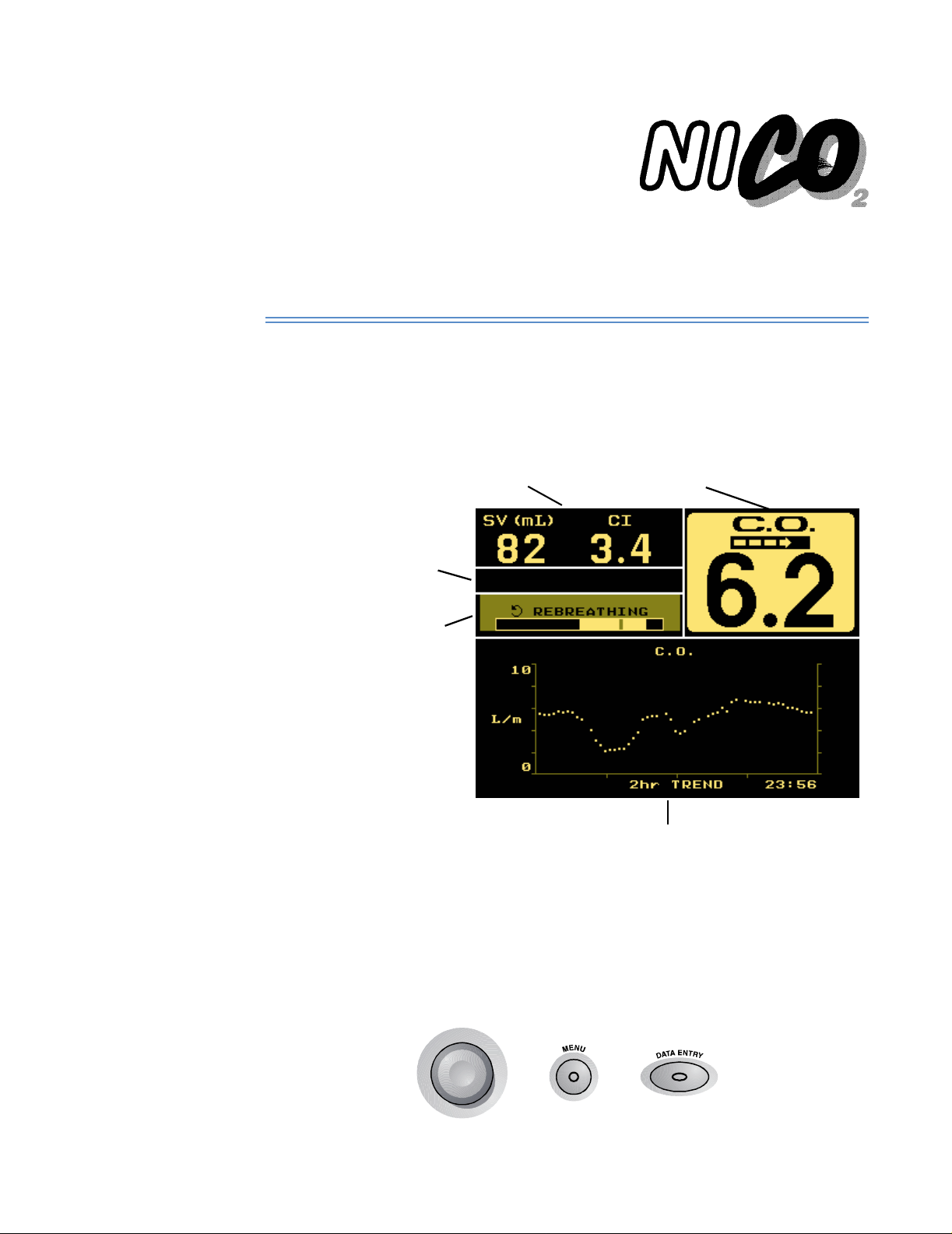
Areas of the Display
The major sections of the Cardiac Output mode screen are identified below.
Stroke Volume (SV) and Cardiac Index
(CI) are displayed in all views. A batter y
icon also appear s if on bat te r y power.
A General Message area
for status, alert and error
information. Displayed in
all views (here shown
blank).
A Cardiac Output Message
area for C.O. info rmation is
displayed in all views.
The Rebreathing Bar is
displayed during the
rebreathing por tion of the
cycle.
Cardiac Output (C.O.) value is displayed
in all views. The CObar™ confidence
indicator is replaced by FAST MODE when
in fast mode.
The lower half of the disp la y pre sen t s tre n d, waveform,
respiratory and numeric data to the user. Various data
entry, setup and aler t menus are also presented here. Use
the KNOB and the MENU and DAT A ENTRY keys to select
the various displays.
Navigating the Display System
Use the KNOB, MENU, and DATA ENTRY keys to navigate the NICO® display system
(as outlined in the following sections).
10 NICO User’s Manual Rev. 05
Page 17
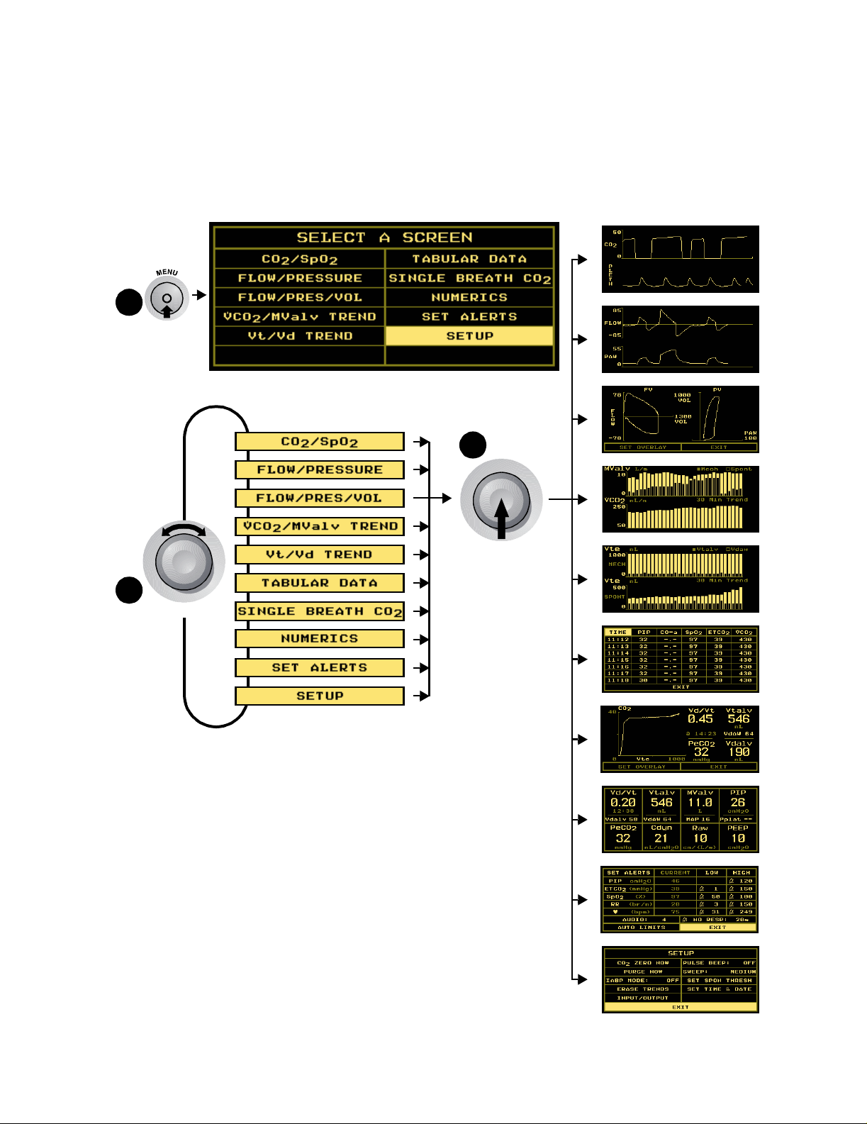
KNOB selectable Monitoring Sc reen s
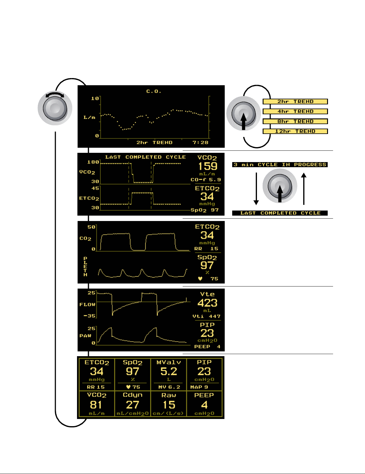
KNOB selectable Monitoring Screens
The KNOB is used to p age through monitoring screens, scroll through menus and make
selections, and to change or enter values. The KN OB is generally turned to access different
monitoring screens and to highlight menu options, and pressed to accept or change select ions.
C.O. Trend Screen
TURN
PUSH
Rebreathing Curves Scre en
PUSH
CO2/SpO2 Screen
(No Options)
Flow/Pressure Screen
(No Options)
Numerics Screen
(No Options)
Rev. 05 NICO User’s Manual 11
Page 18
KNOB selectable Monitoring Sc reen s
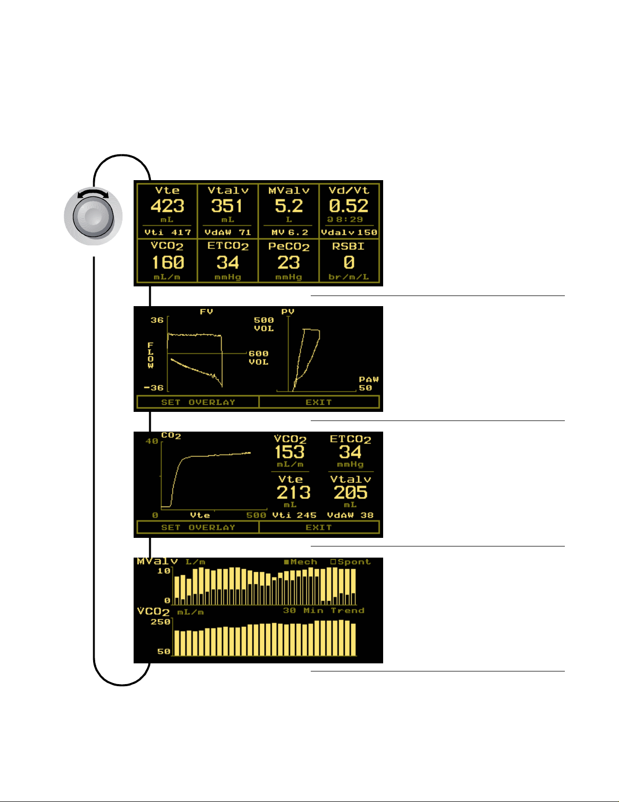
KNOB Selectable Respiratory Screens
TURN
The following Respiratory Screens are available in the monitoring mode only when activated.
Press the MENU key and se lect RESP SCREENS from the SELECT A SC RE EN m enu by tur n ing a nd the n
pressing the KNOB.
From the ADD RESPIRATORY SCREENS menu, highlight and then select which screens will appear in
the base m oni toring mode by tur ning and the n pre ssing the KNOB . Wh en ena bled, select ed
screens can be di splayed by tur n ing the KNOB while vie wing any m on it o rin g scr een.
Respiratory Numerics
Flow Volume Loop and
Pressure Volume Loop
Single Breath CO2 Waveform
/MValv Trend
VCO
2
12 NICO User’s Manual Rev. 05
Page 19
MENU key Screen Displays
1
PUSH
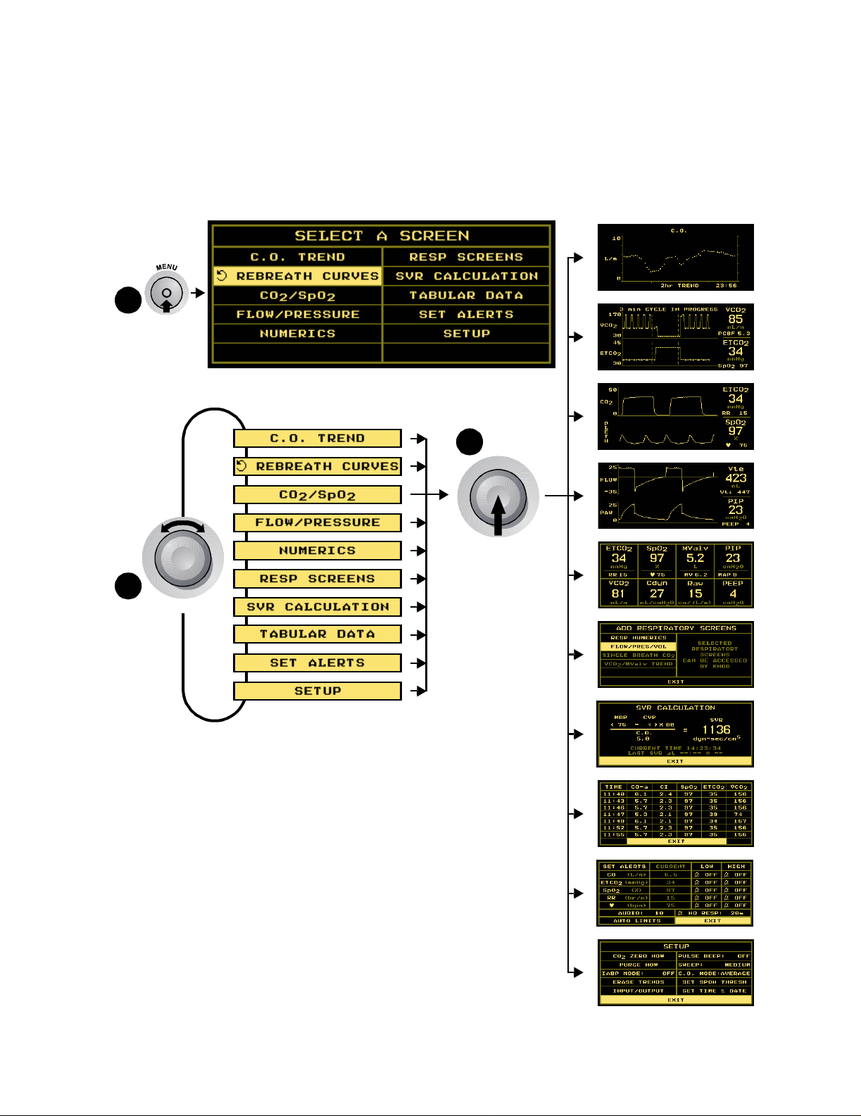
MENU key Screen Displays
Press the MENU key to activate the SELECT A SCREEN menu and illumina te th e key ’s green ic o n.
Press the key again to re tu r n to th e previousl y di s played scre en . From the SE L EC T A SC RE EN menu
turn the KNOB to highlight the screen you wish to d isplay. Press the MENU key or the KNOB to
display that selected screen.
3
PUSH
2
TURN
Rev. 05 NICO User’s Manual 13
Page 20
DATA ENTRY key Screen Displays
DATA ENTRY key Screen Displays
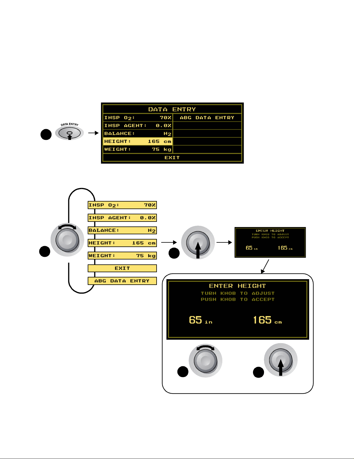
Press the DATA ENTRY key to activate the DATA ENTRY screen and illuminate the key’s green icon.
Press the key again to return to the previously displayed screen. From the DATA ENTRY screen,
you can enter patient information including height, weight and respiratory gas mixture, and
access the ABG DATA ENTRY scr een. (See “Enterin g Pat ien t D at a ” o n pa ge 28 for det ail s .)
1
PUSH
2
TURN
3
PUSH
4
TURN
TO ADJUST
5
PUSH
TO ACCEPT
14 NICO User’s Manual Rev. 05
Page 21
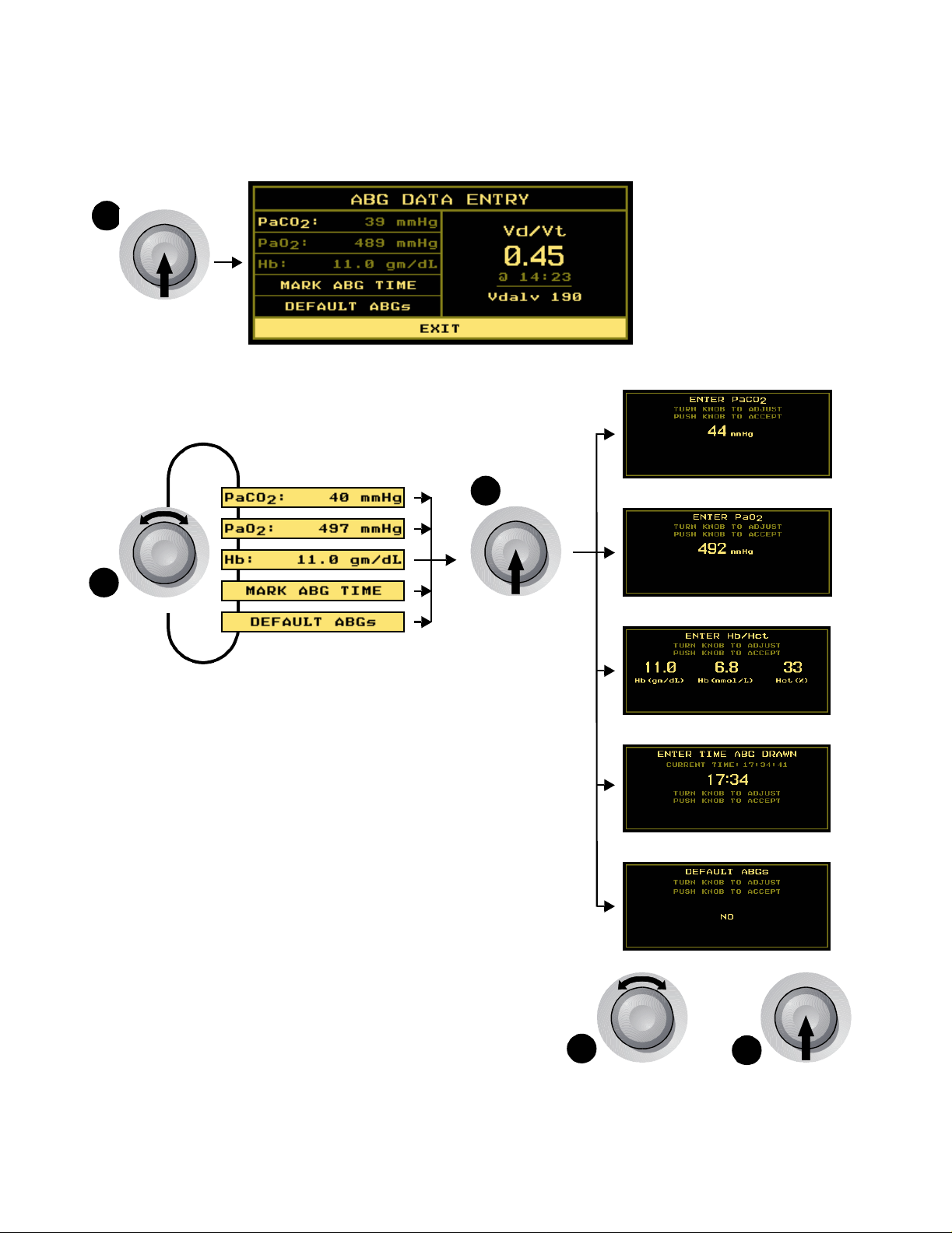
DATA ENTRY key Screen Displays
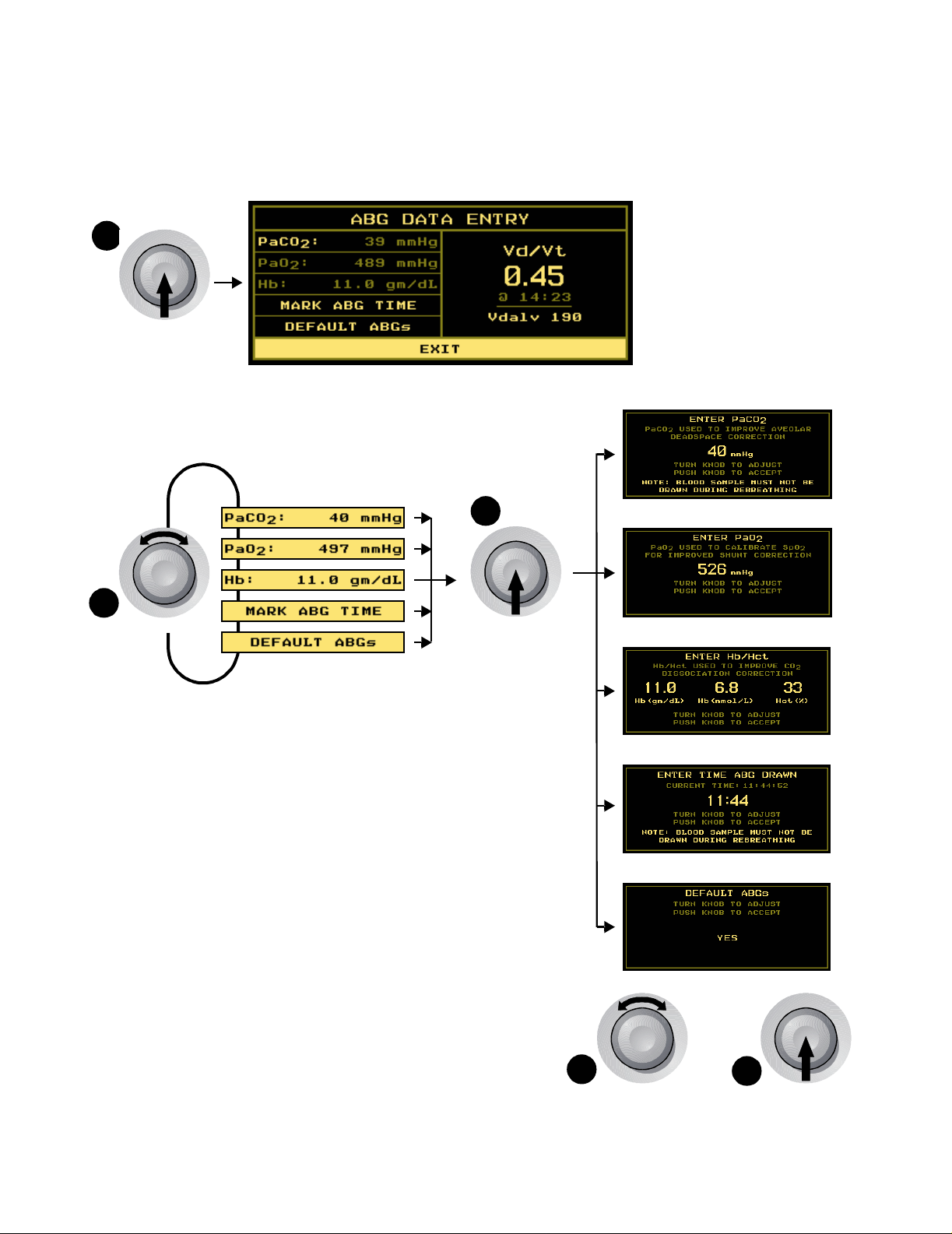
ABG Data Entry Screens
1
PUSH
From the DATA ENTRY screen, select ABG DATA ENTRY. Turn and press the KNOB to enter PaCO2,
PaO
, and Hemoglobin entry screens. (See “Entering Patient Data” on page 28 for details.)
2
3
2
TURN
PUSH
4
TURN
TO SE LECT
Rev. 05 NICO User’s Manual 15
5
PUSH
TO ACCEPT
Page 22
Areas of the Display
Navigating in Respiratory Mechanics mode
Areas of the Display
The major sections of the Respiratory Mechanics mode screen are identified below.
Respiratory data including end tida l
CO2, respiration rate, saturation, and
pulse rate is displayed in all views.
A General Message area for
status, alert and error
information is disp layed in
all views . A battery ic o n
also appears if on bat te r y
power.
The lower half of the display presents trend, waveform, respiratory
and numeric data to the user. Various data entry, setup and alert
menus are also presented here. Use the KNOB and the MENU and
DATA ENTRY keys to select the various displa ys.
Parameters change
depending o n selected
screen.
Navigating the Display System
Use the KNOB, MENU, and DATA ENTRY keys to navigate the NICO® display system
(as outlined in the following sections).
16 NICO User’s Manual Rev. 05
Page 23
KNOB selectable Monitoring Sc reen s
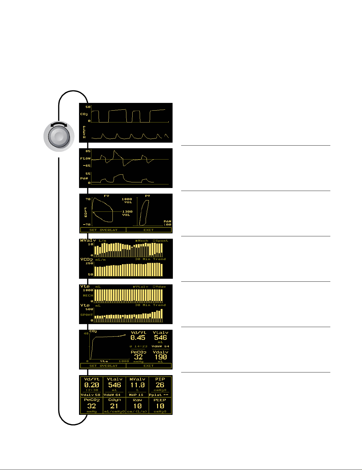
KNOB selectable Monitoring Screens
The KNOB is used to p age through monitoring screens, scroll through menus and make
selections, and to change or enter values. The KN OB is generally turned to access different
monitoring screens and to highlight menu options, and pressed to accept or change select ions.
TURN
CO2/SpO2 Screen
Flow/Pressure Screen
Flow Volume Loop and
Pressure Volume Loop
VCO
/MValv Trend
2
Vtalv/Vdaw Trend
Single Breath CO2 Screen
Respiratory Numerics Screen
Rev. 05 NICO User’s Manual 17
Page 24
MENU key Screen Displays
1
PUSH
MENU key Screen Displays
Press the MENU key to activate the SELECT A SCREEN menu and illumina te th e key ’s green ic o n.
Press the key again to re tu r n to th e previousl y di s played scre en . From the SE L EC T A SC RE EN menu
turn the KNOB to highlight the screen you wish to d isplay. Press the MENU key or the KNOB to
display that selected screen.
3
PUSH
2
TURN
18 NICO User’s Manual Rev. 05
Page 25

DATA ENTRY key Screen Displays
DATA ENTRY key Screen Displays
Press the DATA ENTRY key to activate the DATA ENTRY screen and illuminate the key’s green icon.
Press the key again to return to the previously displayed screen. From the DATA ENTRY screen,
you can enter patient information including height, weight and respiratory gas mixture, and
access the ABG DATA ENTRY scr een. (See “Enterin g Pat ien t D at a ” o n pa ge 28 for det ail s .)
1
PUSH
2
TURN
3
PUSH
4
TURN
TO ADJUST
5
PUSH
TO ACCEPT
Rev. 05 NICO User’s Manual 19
Page 26
DATA ENTRY key Screen Displays
ABG Data Entry Screens
1
PUSH
From the DATA ENTRY screen, select ABG DATA ENTRY. Turn and press the KNOB to enter PaCO2,
PaO
, and Hemoglobin entry screens. (See “Entering Patient Data” on page 28 for details.)
2
3
2
TURN
PUSH
4
TURN
TO SE LECT
5
PUSH
TO ACCEPT
20 NICO User’s Manual Rev. 05
Page 27

Warnings
Safety
For maxim um patient and operator safety, observe th e fo llowing warni n gs , cautions and notes .
WARNING:
Indicates a potent ia lly harmful condition th at can le ad to pe r son a l inju ry.
!
• Explosion Haza rd: Do not use the NICO® monitor in the presence of flammable
anesthet ics . Use of this inst r u ment in such an env ir o n ment may pres ent an explosio n
hazard.
®
• Electrical Shock Hazard: Always turn the NICO
with a damaged externa l p o wer sour ce . Refer ser vicing to qualified service personnel.
• Connect the AC Mains power cord to a properly grounded hospital-gra de outlet. The NICO
monitor should be connected to the same electrical circuit as other equipment in use on
the pati en t. Outlets o f the same cir cuit can be identified by mem bers of the h ospital’s
engineering department.
• Failure of Operation: If the monit or fails to respond as described, do not use it until the
situation has been co rr ect ed by qua lif ied pe r so nn e l.
• Reuse (disassembly, cleaning, disinfecting, resterilizing, etc.) of the CO
NICO Sensors™ may compromise device functionality and system performance and cause
a potential patient hazard. Performance is not guaranteed if a sensor is reused.
•Inspect the CO
• Do not use if they appear to be damaged or broken.
• Do not att em pt to rotat e the NICO Se n so r™ in the br eathing circ uit by gras ping the
pneumatic tubes exiting the flow sensor.
• Do not apply excessive tension to any cable or pneumatic tubing.
• Periodically inspect sensor tubing lines for kinks.
• Replace the CO
observed in the tubing.
®
•NICO
• Do not use the NICO
• In the ev ent the message NICO SENSOR FAILUR E is displayed, remove the NICO Sensor™ from
•The CO
• NICO Sensors™ increa ses airway deadspace by 35 cc (m inim um). At low tidal volumes,
• NICO Sensors™ ar e not for pediatri c u s e.
automatically identifies the type of sensor (small, standard or large NICO S ensor™,
or neonatal, pediatric or adult CO
identification message is not displayed when a sensor is first connected, DO NOT use the
sensor. If the condition persists, refer the monitor to qualified service personnel.
NICO Sensor™. If the condition persists, refer the monitor to qualified service personnel.
the pati ent circuit .
/Flow or NICO Sensor™ connector should be properly inserted into the front panel
2
receptacle prior to connecting a sensor to the breathing circuit, in order to avoid a circuit
leak, or occlusion of sensor tubing.
compensatory changes to ventilation protocol should be considered.
, CO2/Flow, SpO2 and NICO Sensors™ prior to use.
2
, CO2/Flow, or NICO Sensor™ if excessive moisture or secretions are
2
/Flow sensor ) when it is connected. If a sensor
2
®
monitor if it is unable to prop erly identify a CO2/Flow sensor or a
monitor off before cleaning it. Do not use
, CO2/Flow and
2
®
Rev. 05 NICO User’s Manual 21
Page 28
Cautions
• Patient Safety: Care should be exercised to assure continued peripheral perfusion distal to
the SpO
sensor site after application.
2
•Inspect the SpO
sensor site for adequate circulation at least once every four hours.
2
• When applying sensors take note of patient’s physiological condition. For example,
burn patien ts may exhibit mor e sen sitivity to heat and pressure and therefore
additional consideration such as more frequent site checks may be appropriate.
• Periodically check sensors and tubing for excessive moisture or secretion build up.
Although NICO
®
automatically purges the lines, excessive moisture or secretions may still
remain.
• While using the sensors, a system leak, such as that caused by uncuf fed endot racheal
tubes or a damaged sen sor may sig nif ica n t ly aff ect flow r e lat ed rea d in gs . These include
flow, volume, pressure, deadspace, CO
parameters.
production and other respiratory mechanics
2
• Do not position sensor cables or tubing in any manner that may cause entanglement or
strangulation.
®
•The NICO
•The NICO
monitor is not intended to be used as an apnea monitor.
®
monitor has no protection against the ingress of water.
CAUTION:
Indicates a condition that may lead to equipment damage or malfunction.
!
• Use only Novametrix approved sensors and accessories with the NICO® monitor.
®
• Do not operate the NICO
• Do not operate the product if it appears to have been dropped or damaged.
• Never sterilize or immerse the monitor in liquids.
• Do not sterilize or immers e sen so rs except as directed in this manual.
• No tension should be applied to any sensor cable or tubing.
• To avoid the effects of excessive moisture in the NICO Sensor™, insert it in the ventilator
circuit with the pneumatic tubes upright. Excessive moisture in the NICO Sensor™ ma y
affect the accuracy of the measurements.
• T o a void the effects of excessive moisture in the measurement circuit, insert the CO
sensor in the ventila tor circuit with the tubes upr ig ht. I m p rop e r plac ement may result in
erroneous data.
• Excessive moisture in th e CO
measurements.
• It is recommended that CO
whenever an aerosolized medication is delivered. This is due to the increased viscosity of
the medications which may contaminate the sensor windows, causing the sensor to fail
prematurely.
• Operate the monitor at temperatures between 10 to +40° C (50 to 104° F),
10-95% R.H. non-condensing.
• Avoid storing the moni to r at temperatures less th an -10° C or greater than +55° C
(<14° F or >131° F) 10-95% R.H. non-condensing
• Observe pr ecautions for electrosta tic discharg e (E SD) and elec tromagne tic interfer en ce
(EMI) to and from other equipment.
• Where electromagnetic devices (i.e., electrocautery) are used, patient monitoring may be
interrupted due to electromagneti c inte r fe ren ce . E lectromagnetic field s up t o 3 V/m will
not adversely affect system performance.
• Cautio n: F e der al (U .S.A .) law r es tric ts thi s de vi ce to sal e, distr ibu ti on, or us e by or on the
order of a l icensed medical pra c titioner.
monitor when it is wet du e to spills or conden sa ti o n .
/Flow sensor tubing may affect the accuracy of the
2
/Flow or NICO Sensors™ be removed from the circuit
2
/Flow
2
22 NICO User’s Manual Rev. 05
Page 29

Notes
NOTE
A point of particular interest or emphasis intended to provide more efficient or convenient
operation.
• In order to ensure proper monitoring of oxygenation and ventilation:
• The use of pulse oximetry is rec o m mended dur in g NI C O® monitoring.
•Setting of ETCO
• A “NO RESPIRATION” alert is not generated when both the CAPNOSTAT
the NICO Sensor™ or CO
• Be certa in that the m onitor is no t in Demo mode while m o n i to r i ng. Demo m ode can be
identified by the flashing DE MO MOD E label in the General Message area o f th e di s p l ay. To
exit De m o m ode and return to normal monitoring m ode, turn the power o ff and back on.
®
•The NICO
monitor contains no user serviceable parts. Refer servicing to qualified service
personnel. A technical Service Manual is available for use by technical personnel.
•Do not attach an SpO
processed when the cuff is inflated. Attach the sensor to the limb opposite to the site used
for the blood pre s s u r e cuff.
• This product and its accessories which have patient contact are free of latex.
®
•The NICO
monitor is Year 2000 compliant.
• Data Validity : Inaccurate SpO
• Incorrect application or use of a sensor
• Significant levels of dysfunctional hemoglobin; carboxyhemoglobin or methemoglobin
• Significant levels of ind o cya nine green, methylene blue , o r oth er intravascular dyes
• Exposure to excessive illum i n atio n such a s sur gic al lam p s—e sp ecially ones with a
xenon light source, or direct sunlight
• Excessive patient movement
•Venous pulsations
• Electrosurgical interf erence
•Use of an IABP.
•NICO
®
measurements will occu r provided the following conditions are met:
• The NICO Senso r™ assembly is properly installed in the patient’s breathing circuit .
• Valid flow and CO
•VCO
•ETCO
is greater than 20 mL/min.
2
is between 15 and 85 mmHg (2.0 - 11.5 kPa or %) during base li n e
2
•ETCO2 is between 15 and 100 mmHg (2 . 0 - 13.5 kPa or %) during rebreat hin g
• The tidal volume is greater than 200ml (sma ll and stan d a rd sizes)
• The tidal volume is greater than 400 ml (large size ).
• The respiratory rate is between 3 and 60 br/min.
•The STOP/CONTINUE REBREATHING key is not illuminated.
®
•NICO
is not paused by the monitor for any other reason (displayed in the C.O.
message area)
•When a new CAPNOSTAT
monitor to another, it must be zeroed before use.
• After the life cycle of the equipment and accessories has been met, disposal should be
accomplished follo wing national and local req uir e m ents.
and SpO2 alert limits is recommended.
2
®
CO2 senso r and
/Flow sensor are disconnected from the NICO® monitor.
2
sensor distal to a blood pressure cuff. Valid data cannot be
2
and Pulse Rate values may be caused by:
2
signals are detected with no significant signal artifact.
2
®
CO2 sensor is attached to the monitor, or is moved from one
Rev. 05 NICO User’s Manual 23
Page 30
Preparing for Use
Monitoring Cardiac Output
This section detail s th e steps ne eded to begi n pa tient mon ito r i ng with the N IC O® monitor.
Preparing for Use
Inspect Before monitoring, take a few moments to inspect the NICO
that all items are cle an, dry, and physically intact wit h n o bro ken o r dam a g ed com pon e n t s .
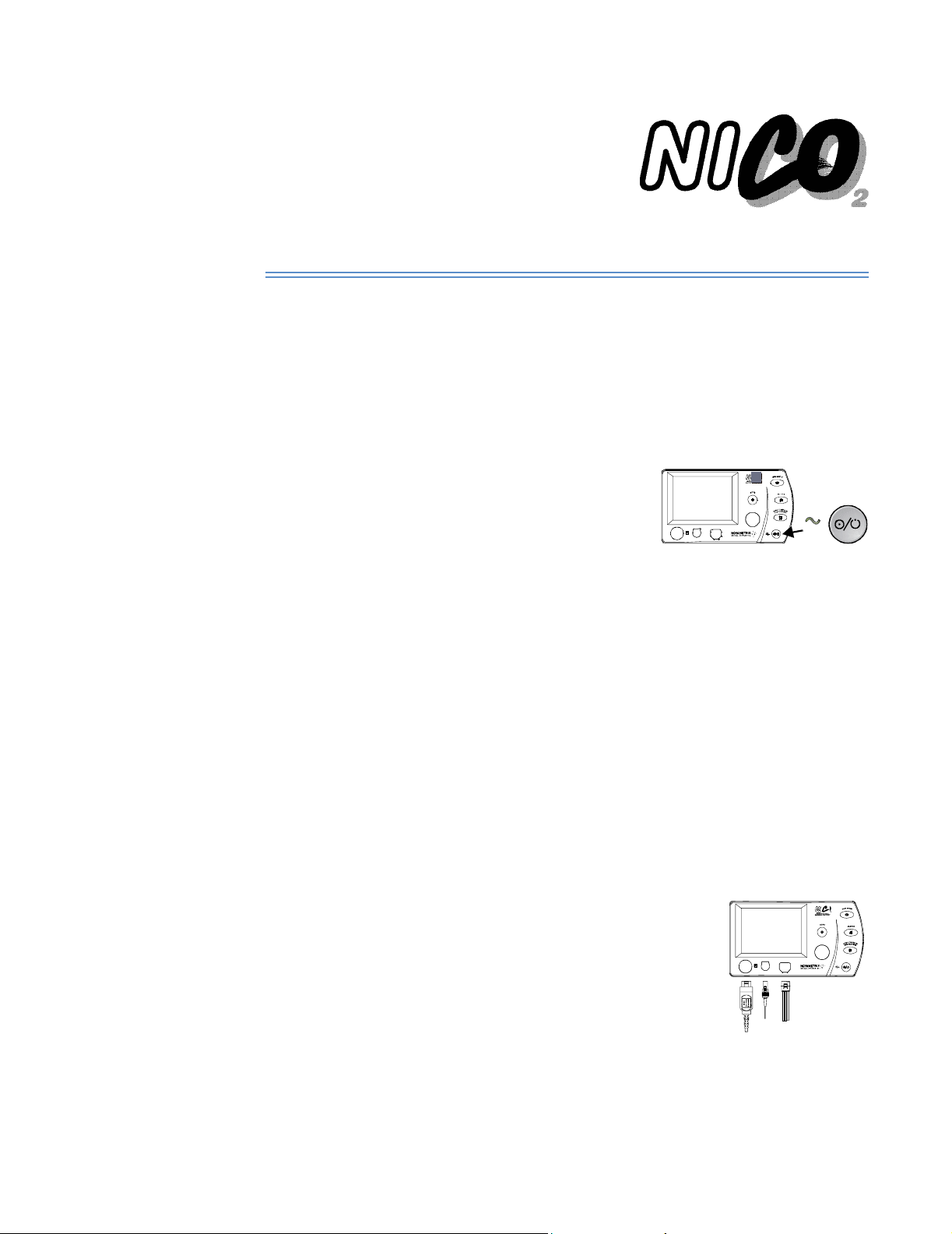
Turn on the monitor Turn the NICO
1 Press the Operate/Standby key to turn the monitor on
and off.
2 The monitor performs a quick self-test.
3 The message PRESS KNOB TO ERASE STORED TRENDS is displayed for 5 seco nds .
4 The power up sequence is completed and a monitori ng scre en is disp layed.
®
monitor on.
®
•NICO
• An audible tone sounds, the key indicators illum inate, and a SELF-TEST IN PROGRESS
• To erase the contents of the monitor’s trend memory, press the knob. TRENDS ERASED
• To retain the contents of the monitor’s trend memory, do not press the knob. Wait the
• Note: If the internal battery becomes fully discharged, the messag e CHECK DATE/TIME
•NICO
• If the monitor is in Respiratory Mechanics mode, connecting a NICO Sensor™ will
• The monitor is in a READY state and the parameters will be dashed and alerts will not
• Parameters will display and their alerts will become active as they are calculated.
can operate from its internal battery or
from the AC Mains. (See “AC/Ba ttery Operation”
on page 4 for details.)
message is briefly displayed.
is brief l y display ed.
5 seconds and TRENDS RETAINED is displayed.
(MENU -> SETUP) will appear before the PRESS KNO B T O ER ASE STOR ED T REN DS message. (See
“Setup Scre en” on page 45 for details .)
®
displays the screen that was displayed when the monitor wa s last turne d off.
cause the monitor to automatically switch to Cardiac Output mode.
be active until parameters are calculated and displayed.
®
monitor and its sensors. Check
Connect and apply the sensors
Connect the sensors to the monitor, ventilator circuit, and patient.
1 Connect the SpO
patient. (See “Pulse Oximetry Sensors” on page 67.)
2 Connect the CAPNOSTAT
(See “CAPNOSTAT® CO2 Sensor” on page 65.)
sensor to the monitor and apply it to the
2
®
CO2 Sensor to th e monitor.
3 Select a NICO Sensor™, see “Choosing a NICO Sensor™ size” on
page 60.
4 Connect the NICO Sensor™ to the monitor and attach a
CAPNOSTAT
®
. (See “NICO Sensor™” on page 59.)
5 Use the Initial Adjustment Template as a guide and adjust the NICO Loop™ to match the
ventilator’s tidal volume set ting , then discard the templ at e. (S ee Instructions on the
®
NICO
template.
24 NICO User’s Manual Rev. 05
Page 31

Begin NICO® monitoring
6 For optimal results, place the NICO Sensor™ into the ventilator circuit between the
endotracheal tube and the ventilator circuit wye.
• Place other devices (HME, filters, etc.) between NICO Sensor™ and the patient
connection.
• The NICO Sensor™ increases airway deadspace by 35 cc (mini m um). At low tidal
volumes, compensatory changes to ventil ation protocol should be consid ered.
• Placement of a sidestream gas analyzer sampling port between the NICO Sensor™
and the patient connection may reduce NICO
• Sidest rea m or mai ns tre am gas an aly zers plac ed be tw een th e NIC O Sen sor ™ and th e
patient ci rcuit “Y” may be inacc urate durin g the rebre athing p hase of the NIC O
• Place the sensor so that the trip le lu men tubing lines exit fro m the top o f the sen so r
(to help keep th em clear an d d r y).
• Keep the sensor clear of accumulations by proper circuit maintenance.
®
accuracy at low tidal volumes.
®
cycle.
NICO Sensor™ and CAPNOSTAT
®
Elbow
Other devices
(HME, filter, etc.)
Disposable a utomat ic
rebreathin g valve
Patient
circu it “Y”
CAPNOSTAT
Patient
connection
®
CO2 Sensor
/Flow
CO
2
Sensor
NICO Loop™
(adjustable
rebreathing
volume)
Anesthesia mach ine/ventilator
circuit connection
Begin NICO® monitoring
After the NICO® monitor is turned on and the sensors are properly connected and applied,
cardiac output monitoring can begin.
1 Press the STOP/CONTINUE REBREATHING key to
initiate monitoring. Subsequent presses will Stop/
Continue the rebreathing process.
• An icon “ “ identifies rebreathin g stat us .
• Illuminated: Rebreathing is DISABLED.
• Not illuminated: Rebreathing is ENABLED.
2 Enter the patient’s height and we ig h t (fo r card ia c inde x ca lcula tions) and the delivered
oxygen, an esthetic age n t a n d balance ga s by pressing th e DATA ENTRY key. (See
“Entering Pat i ent Data” on page 28 .)
3 If available, enter the patient’s PaCO
ENTRY screens, then mark the ABG time before exiting. (See “Entering Patient Data” on
page 28.
, PaO2, hemoglobin and hematocrit in the ABG DATA
2
Rev. 05 NICO User’s Manual 25
Page 32

Begin NICO® monitoring
NOTE: Vd/Vt Phy, Vd Phy, and Vd alv are calcu lat ed based on the PaCO
entered, and are not updated until the next time the PaCO
4 As you begin monito r i ng with NI CO
• Reliance on Cardiac Output parameters (NICO
®
, please note the foll o w ing:
®
, SV & CI) should be taken in context
with other monitor ing parame ters and the ph y si o logic condition of the patient .
• Entry of patient height and weight is required to calculate and display Cardiac Index.
• Pulse oximetry is required to calculate and display Stroke Volume (SV).
• Accuracy of cardiac output and related parameters will be affected by the following:
• Significant fluctuations in mixed venous CO
content or metabolic CO2 production
2
during any three minute measurement period.
•Sudden release of CO
• The presence of excessive moisture or secretions in the NICO
into the bloodstream, such as when releasing a cross clamp.
2
• Entry of blood gas information.
• Due to the periodic rebreathing for NICO
®
measurements, the patient's effective
ventilation will be red u ce d by typ ica lly 10-15% (depending on the rebreathing
volume required). This can be offset by increasing the minute ventilation before
®
NICO
monitoring begins.
Rebreathing Bar The Rebreathing Bar visually indicates the level of patie nt
rebreathing. Under normal monitoring conditions, the
REBREATHING icon and Rebreathing Bar appear in the
message center each time the aut omatic rebre athing cycl e
begins.
• The Rebreathing Bar represents the total possible range of rebreathing from 0-100%.
• The highlighted area within the bar represents the target rebreathing range (50%-90%)
for optimal NICO
• A verti cal poi nter w ithin the R ebreath ing Bar indic ates t he curre nt re breathi ng perc entage.
• The pointer will appear within the highligh t ed area of the Reb r eathing Bar wh en the
NICO Loop™ i s p rope rl y siz ed a nd pr ovi ding an a cce ptabl e pe rcen tage of re bre athin g.
• Note: The word “OK” will disappear when the pointer falls within that area of the
highlighted bar.
• The Rebreathing Bar is not displayed when the ratio of spontaneous to mechanical breaths
is greater than or equa l to 2:1.
®
performance.
value last
value is entered or changed.
2
2
®
sensor.
Expand/Retract NICO Loop™
• If the NICO Loop™ is not sufficiently expanded and
the Rebrea th i ng Bar pointer fall s below 50%, the
message EXPAND LOOP is d isp layed during the
rebreathin g period.
• If the NICO Loop™ is over-expanded and the
Rebreathing Bar pointer is above 90%, the message
RETRACT LOOP is displayed during the rebreathing period.
To expand or retract the NICO Loop™:
1 Grasp the NICO Loop™ with one hand and the automatic rebreathing valve with the other
hand so as not to disturb/disconnect the breathing circuit while adjusting the loop.
2 Expand or retract the NICO Loop™ 3-6 inches.
• It may tak e 2-3 additio n al breaths before th e i con change s .
• Note that if the loop is still not appropriat ely sized by the end of the r eb reathing
period, the message will be removed and may be displayed again during the next
rebreathin g period.
Sensor Size Message If the EXPAND or RETRACT LOOP message appears for more
than three rebreathing cycles, and resizing the NICO Loop™
was not effective, the NICO
different sized sensor to correct the condition. See “Status
Messages” on page 61.
®
monitor will suggest a
26 NICO User’s Manual Rev. 05
Page 33

Begin NICO® monitoring
The NICO® Cycle Once rebreathing is enabled, the NICO
output measurement cycle. This NICO® cycle has three phases:
• Baseline: During the 60-seconds baseline period the rebreathing valve inside the NICO
Sensor™ is turned off and the rebreathing volume of the NICO Loop™ is bypassed. During
Rebreathing On/Off or Paused
this time, VCO
• Rebreathing: The 50-second rebreathing period starts when the monitor turns on the
rebreathing valve inside the NICO Sensor™ causing the rebreathing volume of the NICO
Loop™ to be adde d into the ci rcuit. During r ebreathing, VCO
become elevated (3-5 mmHg, typical) and mixed venous CO
NOTE: The rebreathing period will typica lly ind u ce an incr ease in PaCO
An ABG blood sample drawn during this period ( REBREATHING displayed) or during the
first twenty seconds of the stabiliza tion pe riod (where NEXT is displayed), may cause
PaCO
values to reflect higher than normal levels.
2
• Stabilization: After completion of rebreathing, a 70-secon d st abilization period begin s,
during which time VCO
®
NICO
updates the displayed C.O. value following the completion of each three minute NICO
cycle. The CObar™ (cardiac output confidence bar) provides an indication of the system’s
confidence in the displayed value. (See “CObar™ Confidence Indicator” on page 31.)
The user can interrupt or resume the rebreathing cycle at any time by pressing the STOP/
CONTINUE REBREATHING key. The NICO
rebreathing cycle—that must be initiated by the user pressing the STOP/CONTINUE
REBREATHING key. Note that once reb reat hin g is init iat ed b y t he u ser, the monitor wi ll, unde r
certain conditions, pause rebreathing until a specified condition (see below) is corrected—at
which time the monitor will restart the r eb reathing.
, PaCO2 and ETCO2 will be at baseline values.
2
, PaCO2 and ETCO2 return to their baseline values.
2
®
monitor automatically repeats a three minute cardiac
is reduced, PaCO2 and ETCO2
2
remains unchanged.
2
by 3-5 mmHg.
2
®
monitor will no t autom aticall y resta rt the
®
Rebreathing can be Off, On, or Paused as indicated below:
Rebreathing OFF (disabled)
•The NICO® monitor starts in this state upon power-up.
•The STOP/CONTINUE REBREATHING key is
illuminated whi le in this state.
®
•The NICO
rebreathing cycle can be placed into this state at any time by pressing the
STOP/CONTINUE REBREATHING key (rebreathing is immediately disabled).
®
•The NICO
rebreathing cycle is automatically turned off for certain monitor/sensor
conditions. (See “(Alert Class: H-High Priority, M-Medium Priority, L -Low Priority, S-Status
Message. See “NICO® Aler t P r io ri t ies ” on page 56 for details.” on page 79.)
• Noted in the cardiac output message area as REBREATHING OFF.
Rebreathing ON (enabled)
• When the monitor is initially turned on, this state is
entered only after pressing the STOP/CONTINUE
REBREATHING key.
•The STOP/CONTINUE REBREATHING key is not
illuminated whi le in this state.
• The cardiac output is calculated and updated while in this state.
• Noted in the cardiac output message area as REBREATHING or NEXT .
Rebreathing Pa u s ed
®
•The NICO
monitor automat ically pauses th e
rebreathing cycle and generates a display message
under any of th ese condition s :
•ETCO
is less than 15 mmHg (2.0 kPa or %) or greater than 85 mmHg (11.5 kPa or %)
2
• Respiration rate is less than 3 or greater than 60 br/min.
•VCO
is less than 20 mL/min.
2
• The rebreathing cycle automatically restarts when the condition is corrected.
Rev. 05 NICO User’s Manual 27
Page 34

Entering Patient Data
Entering Patient Data
NICO® monitoring can be enhanced by the entry of key patient specific data including respired gas
compos iti on ( an est h et ic ag ent , ba la nc e g a s, a nd in s pir e d O2), patient height and weight, and
arterial blood gas data (PaCO
when gas exchange impairment is expected (i.e., high shunt or deadspace). ABG samples
should not be obtained during the rebreathing phase of the 3-minute NICO
Patient data should be updated in the DATA ENTRY screen whenever poss ible. The scre en may be
accessed at any time by pressing the DATA ENTRY key.
DATA ENTRY settings The followi n g table list s th e parameter s a n d r anges acces sible in the DATA ENTRY scree ns.
Label Parameter Default Range/Units Description
, PaO2, Hb or Hct ). Incl usion of ABG data is esp ecia lly im port ant
2
®
cycle.
INSP O
INSP
AGENT
2
Inspired
Oxygen
Inspired
Anesthetic
70% 21-100 % Percent of oxygen in the inspired gas.
0% 0-20 % Percent of anesthetic agent in the
Agent
BALANCE Gas Balance N
2
N2, He, or N2ON
HEIGHT Patient Height -- 35-91 in
90-230 cm
WEIGHT Patient Weight -- 55-551 lb
25-250 kg
ABG DATA ENTRY Screen
PaCO
2
Arterial Carbon
Dioxide
40 mmHg
(5.4 kPa or %)
0-250 mmHg
0.0-20.0 kPa
0.0-20.0 %
(“--” displayed until an
initial value is entered)
PaO
2
Arterial Oxygen FiO2 (Pb-47 mmHg)
Hb Hemoglobin
Concentration
or Hematocrit
(“--” displayed until an
initial value is entered)
11.0 gm/dL
6.8 mmol/L
33 %
0-750 mmHg
0.0-99.5 kPa
0.0-99.5 %
Hb: 5.0-20.0 gm/dL
Hb: 3.1-12.4 mmol/L
Hct: 0-60 %
(“--” displayed until an
initial value is entered)
MARK ABG
TIME
Time when ABG
blood sample is
Current Time hh:mm
(hours:minutes)
drawn
DEFAULT
ABGs
Blood gas
values
: 5 mmHg
PaCO
2
(0.7 kPa or %) above
the measured ETCO
a
value
2
Must be entered in order for NICO® to
accurately calculate parameters.
inspired gas. Must enter percent
delivered in ord er for NI C O
®
to
accurately calculate parameters.
, He or N2O. Must select the correct
2
balance in the in sp ir ed ga s in o rde r for
®
NICO
to accurately calculate
parameters.
Enter patient he ight for CI ca lc ulation s.
Enter pa ti ent weigh t for CI calc u lations.
Partial pressure of carbon dioxide in
arterial blood. Entering this value can
enhance the accuracy of NICO
®
parameters.
Partial pressure of oxygen in arterial
blood. Entering this value can enhance
the accuracy of NICO
®
parameters.
Concentration of hemoglobin or
hemato crit in the blo od. Enter i n g th i s
value can enhance the accuracy of
®
NICO
parameters.
Enter time ABG is drawn. (Only accepts
time since ETCO
was fir st detected.)
2
Resets blood gas settings to default
values.
PaO2: Based on
barometric pressure
and INSP O
value.
2
Hb: 11.0 gm/dL
a.40mmHg (5.4 kPa or %) if ETCO
is not available.
2
28 NICO User’s Manual Rev. 05
Page 35

Entering ABG Data
Entering Patient Data To enter (or view) patient data:
1 Press the DATA ENTRY key to activate DATA ENTRY. The key’s green icon illuminates.
• Press the key again to return to the previously displayed screen.
2 Highlight the desired data by turning the KNOB.
3 Select th e highlighted dat a by pressin g the KNOB.
4 Turn t he KNOB to adj u st the value as de s ired.
5 Press the KNOB to accept the value.
6 Repeat these steps for the other settings.
1
PUSH
3
PUSH
2
TURN
4
TURN
TO ADJUST
5
PUSH
TO ACCEPT
Entering ABG Data
To ent e r ABG data:
1 Draw blood sample during the “normal” phase of the
NICO® cycle, not du ring the rebreathing phase.
• The cardiac output messa ge will display how
much time before the next rebreathing phase occurs.
Rev. 05 NICO User’s Manual 29
Page 36

Entering ABG Data
1
PUSH
2 Press the DATA ENTRY key to activate DATA ENTRY. The key’s green icon illuminates.
• Press the key again to return to the previously displayed screen.
3 Highlight ABG DATA ENTRY by turning the KNOB.
4 Select ABG DATA ENTRY by pressing the KNOB.
3
2
TURN
PUSH
4
TURN
TO SE LECT
5
PUSH
TO ACCEPT
30 NICO User’s Manual Rev. 05
Page 37

C.O. Averaging
CObar™ Confidence Indicator
5 Turn and press the KNOB to select the PaCO
ABG screen.
, PaO2, Hb/Hct, Mark ABG Time or Default
2
6 Turn KNOB to adjust value.
• ABG Time is required for P aCO
• Ensur e th at th e NI CO
time.
®
clock is synchronized to the clock used to determine the draw
and PaO2.
2
7 Press the KNOB to accept the value and return to the ABG DATA ENTRY scre en.
• Updated Vd/Vt and Vdalv values are displayed.
C.O. Averaging
The Cardiac O utp ut Co nfid ence B ar, or CObar™, is an ind icator
of the system’s confidence in the currently displayed card iac
output value. The CObar indicator is located above the cardiac
output value a nd c an c onta in up to five s egm ent s. Th e d egree
of confidence (more segments for higher confidence, fewer
segments for lower con fidence ) is based on m ultiple f actors
including ventilatory pattern, sizing of the NICO Loop™, tidal
volume, en try of pati en t data and br eathin g ci r c u it integr ity.
At higher confidence levels the system can more quickly
resolve changes in C.O. and is therefore able to display those
changes more quickly. At lower confidence levels, the system must work harder at resolving
C.O. change s, there by de layin g how q ui ckly t hat inf orma tion can be d isp layed . Th e delay fr om
detection to display of changes in C.O. can range from:
• 5 seg ments: 1.5 - 2 minu tes
• 4 segments: 3 - 7 minutes
• 3 seg ments: 5 - 9.5 minu tes
• 2 seg ments: 7 - 9.5 minu tes
• 1 segment: 8.5 - 9.5 minutes
A lower number of segments indicates that the displayed cardiac output reading is being
averaged more with readings from previous NICO
If there is no confidence in the signals, the C.O. value is not displayed and no segments are
displayed in the CObar.
The CObar is dis played when the C.O. MODE is set to AVERAGE in the SETUP scre en.
®
rebreathing cycles.
C.O. Fast Mode When the C.O. MODE is set to FAST, the monitor will display the
unfiltered C.O. value (CO-f ) rat her th an the averaged value.
The text FAST MODE will replace the CObar graphic. The stroke
volum e and ca rdiac index will be calcu lated from th is valu e
rather th an the averaged value.
The averaged C.O. value can still be viewed as CO-a under the
VCO
value in the LAST COMPLETED CYCLE screen.
2
The C.O. MODE option is set in the SETUP screen.
Rev. 05 NICO User’s Manual 31
Page 38

Preparing for Use
Respiratory Monitorin g
This section details the steps needed to begin patient respiratory mechanics monitoring with the
®
NICO
monitor.
Preparing for Use
Inspect Before monitoring, take a few moments to inspect the NICO
that all items are cle an, dry, and physically intact wit h n o bro ken o r dam a g ed com pon e n t s .
Turn on the monitor Turn the NICO
1 Press the Operate/Standby key to turn the monitor on
and off.
2 The monitor performs a quick self-test.
3 The message PRESS KNOB TO ERASE STORED TRENDS is displayed for 5 seco nds .
4 The power up sequence is completed and a monitori ng scre en is disp layed.
®
monitor on.
®
•NICO
• An audible tone sounds, the key indicators illum inate, and a SELF-TEST IN PROGRESS
• To erase the contents of the monitor’s trend memory, press the knob. TRENDS ERASED
• To retain the contents of the monitor’s trend memory, do not press the knob. Wait the
• Note: If the internal battery becomes fully discharged, the messag e CHECK DATE/TIME
•NICO
• If the monitor is in Cardiac Output mode, connecting a CO
• The monitor is in a READY state and the parameters will be dashed and alerts will not
• Parameters will display and their alerts will become active as they are calculated.
can operate from its internal battery or
from the AC Mains. (See “AC/Ba ttery Operation”
on page 4 for details.)
message is briefly displayed.
is brief l y display ed.
5 seconds and TRENDS RETAINED is displayed.
(MENU -> SETUP) will appear before the PRESS KNO B T O ER ASE STOR ED T REN DS message. (See
“Setup Scre en” on page 45 for details .)
®
displays the screen that was displayed when the monitor was last turned off.
monitor to automatically switch to Respiratory Mechanics mode.
be active until parameters are calculated and displayed.
®
monitor and its sensors. Check
/Flow sensor will cause the
2
Connect and apply the sensors
Connect the sensors to the monitor, ventilator circuit, and patient.
1 Connect the SpO
patient. (See “Pulse Oximetry Sensors” on page 67.)
2 Connect the CAPNOSTAT
(See “CAPNOSTAT® CO2 Sensor” on page 65.)
3 Select an appropriate size CO
4 Connect a CO
CAPNOSTAT
sensor to the monitor and apply it to the
2
®
CO2 Sensor to th e monitor.
/Flow sensor.
2
/Flow Sensor to the monitor and attach a
2
®
. (See “CO2/Flow Sensor s” on pag e 62.)
32 NICO User’s Manual Rev. 05
Page 39

Preparing for Use
5 Connect the CAPNOSTAT CO
CAPNOSTAT
sensor
CO
2
Combined CO
(added deadspace: < 8.5 cc)
/Flow sensor
2
6 For optimal results, place the CO
endotracheal tube and the ventilator circuit wye.
• Place the sensor pro xim a l to the patient if using othe r dev ice s in the circuit.
• Place the sensor so that the tubing lines exit from the top of the sensor (to help keep
them clear and dry).
• Keep the sensor clear of accumulations by proper circuit maintenance.
7 Connect the combined CO
sensor to the CO2/Flow sensor.
2
Pediatric
Combined CO
(added deadspace: < 4 cc)
/flow sensor
2
Combined CO
(added deadspace: < 1 cc)
CAPNOSTAT
sensor
CO
2
/Flow sensor in the ventilator circuit between the
2
/Flow se n s o r to the patie n t b reathing ci r c uit.
2
CAPNOSTATPediatric/adult
CO
Neonatal
/flow sensor
2
sensor
2
To patient
Adult CO
/Flow sensor
2
with CAPNOSTAT CO
sensor attach ed
To
patient
To
ventilator
2
Neonatal CO
with CAPNOSTAT CO
sensor attached
To patient
/Flow sensor
2
2
To
ventilator
Pediatric CO
with CAPNOSTAT CO
/Flow sensor
2
2
sensor attached
To
ventilator
Rev. 05 NICO User’s Manual 33
Page 40

Begin Respiratory Monitoring
• Do NOT place the CO
circuit), as this may allow patient secretions to block the adapter windows.
• Position the CO
this helps keep patient secretions from “pooling” on the windows.
• To prevent “rain-out” and moisture from dr aini ng into the CO
the CO
/Flow sensor in a gravity depen dent position.
2
• Periodically check the CO
/Flow sensor between the ET tube and the elbow (pediatric/adult
2
/Flow sensor with its windows in a vertical and NOT a horizontal position:
2
/Flow sen sor, do NOT pl ace
2
/Flow sensor and tubing for excessive moisture or secretion build up.
2
• For routine performance of airway care, separate the system between the ET tube and the
airway adapter (ne o n atal circui t), or between the ET tube and elbow (pedi atric/adu l t
circuit). Lavage and suctioning of the airway can then be performed without fluids and
mucous accumulating on the CO
/Flow sensor windows.
2
Begin Respiratory Monitor i ng
After the NICO® monitor is turned on and the sensors are properly connected and applied,
Respiratory Mechanics monitoring can begin.
1 Enter the delivered oxygen and balance gas or
anesthet ic agent if pres en t, by pressin g t h e DATA
ENTRY key. (See “Entering Patient Data” on
page 34.)
2 As you begin monito r i ng with NI CO
the following:
• Water that acc umulate s i n the CO
reported Tidal Volumes to be higher than set volumes. If reported values are higher
(or lower) tha n exp ected and wate r is seen in the line or sens or bo d y, purge the
lines. If purging does not clear the water, remove the sensor from the circuit and
remove the water by shaking the sensor, or by flowing oxygen or compressed air
through the tubing or sensor until the water is removed. Do not use high pressure for
water removal.
• To minimize the effects of aerosolized medications on the CO
ommend ed th a t the CO
the delivery of the medication. The decision to remove or not remove the CO2/
Flow sensor is the responsibility of the clinician.
• During the purge cycle the pump will be heard.
• Water will condense in the pressure sense lines at a faster rate when used in cooler
ambient temperatures.
•Always keep the CO
pooling of water and se cr et io ns at the pressure sense line openings.
• The automatic purge mode may not be disabled.
• During a very low battery co ndi tion, automatic and manua l purg in g is no t allo wed.
/Flow sensor be removed from the ventilator circuit prior to
2
/Flow sensor tubing pointed in an upward position to minimize
2
®
, please note
/Flow sensor or the sensor tubing may cause the
2
/Flow sensor, it is rec-
2
Entering Patient Data
Respiratory monitoring can be enhanced by the entry of key patient specific data including
respired gas composition (anesthetic agent, balan ce g as, and in spired O
Patient data should be updated in the DATA ENTRY screen whenever poss ible. The scre en may be
accessed at any time by pressing the DATA ENTRY key.
34 NICO User’s Manual Rev. 05
).
2
Page 41

Entering Patient Data
DATA ENTRY settings The followi n g table list s th e parameter s a n d r anges acces sible in the DATA ENTRY scree ns.
Label Parameter Default Range/Units Description
INSP O
INSP
AGENT
BALANCE Gas Balance N
HEIGHT Patient Height -- 35-91 in
WEIGHT Patient Weig ht -- Neonatal:
ABG DATA ENTRY Screen
2
Inspired
Oxygen
Inspired
Anesthetic
Agent
70% 21-100 % Percent of oxygen in the inspired gas.
Must be entered in order for NICO
accurately calculate parameters.
0% 0-20 % Percent of anesthetic agent in the
inspired gas. Must enter percent
delivered in ord er for NI C O
®
to
accurately calculate parameters.
2
N2, He, or N2ON
, He, or N2O. Must select the correct
2
balance in the in sp ir ed ga s in o rde r for
®
NICO
to accurately calculate
parameters.
Enter patient height.
90-230 cm
Enter pa ti ent weigh t for respi rat o r y
0.22 - 44 .09 lb
mechanics calculations.
0.10 - 20 .00 kg
Pediatric:
0.2 - 220.2 lb
0.1 - 99.9 kg
Adult:
55-551 lb
25-250 kg
®
to
PaCO
PaO
2
2
Arterial Carbon
Dioxide
Arterial Oxygen FiO2 (Pb-47 mmHg)
Hb Hemoglobin
Concentration
or Hematocrit
MARK ABG
TIME
Time when ABG
blood sample is
drawn
DEFAULT
ABGs
Blood gas
values
a.40 mmHg (5.4 kPa or %) if ETCO
40 mmHg
(5.4 kPa or %)
0-250 mmHg
0.0-20.0 kPa
0.0-20.0 %
(“--” displayed until an
initial value is entere d)
0-750 mmHg
(“--” displayed until an
initial value is entere d)
11.0 gm/dL
6.8 mmol/L
33 %
0.0-99.5 kPa
0.0-99.5 %
Hb: 5.0-20.0 gm/dL
Hb: 3.1-12.4 mmol/L
Hct: 0-60 %
(“--” displayed until an
initial value is entere d)
Current Time hh:mm
(hours:minutes)
: 5 mmHg
PaCO
2
(0.7kPa or %) above
the measured ETCO
a
value
2
PaO2: Based on
barometric pressure
and INSP O
valu e .
2
Hb: 11.0 gm/dL
is not available.
2
Partial pressure of carbon dioxide in
arterial blood. Enter this value for
calculation of Vd a lv (a lveo la r
deadspace), Vd/Vt (deadspace to tidal
volume ratio) and Vd phys (physiologic
deadspace).
Partial pressure of oxygen in arterial
blood.
Enter a value for this parameter if
desired; does not affect CO
/flow
2
calculations.
Concentration of hemoglobin or
hematocrit in the blood.
Enter a value for parameter if desired;
does not affect CO
/flow calculations.
2
Enter time ABG is drawn. Only accepts
time since ETCO
was fir st detected.
2
Resets blood gas settings to default
values.
Rev. 05 NICO User’s Manual 35
Page 42

Entering ABG Data
Entering Patient Data To enter (or view) patient data:
1 Press the DATA ENTRY key to activate DATA ENTRY. The key’s green icon illuminates.
• Press the key again to return to the previously displayed screen.
2 Highlight the desired data by turning the KNOB.
3 Select th e highlighted dat a by pressin g the KNOB.
4 Turn t he KNOB to adj u st the value as de s ired.
5 Press the KNOB to accept the value.
6 Repeat these steps for the other settings.
1
PUSH
3
PUSH
2
TURN
4
TURN
TO ADJUST
5
PUSH
TO ACCEPT
Entering ABG Data
To ent e r ABG data:
1 Press the DATA ENTRY key to activate DATA ENTRY. The key’s green icon illuminates.
• Press the key again to return to the previously displayed screen.
2 Highlight ABG DATA ENTRY by turning the KNOB.
36 NICO User’s Manual Rev. 05
Page 43

Entering ABG Data
1
PUSH
3 Select ABG DATA ENTRY by pressing the KNOB.
3
2
TURN
PUSH
4
TURN
TO SE LECT
Rev. 05 NICO User’s Manual 37
5
PUSH
TO ACCEPT
Page 44

Entering ABG Data
4 Turn and press the KNOB to select the PaCO
ABG screen.
NOTE: PaO
that, although they are available for data input, the data will not affect parameter
calulations.
and Hb selections are dimmed in Respiratory Mechanics mode to denote
2
, PaO2, Hb/Hct, Mark ABG Time or Default
2
5 Turn KNOB to adjust value.
• ABG Time is required for P aCO
• Ensur e th at th e NI CO® clock is synchronized to the clock used to determine the draw
time.
.
2
6 Press the KNOB to accept the value.
• Updated Vd/Vt and Vdalv values are displayed.
38 NICO User’s Manual Rev. 05
Page 45

Cardiac Output mode
Monitoring and Setup Screens
Cardiac Output mode
This section provides an overview of monitoring and setup screens in Cardiac Ou tput mode .
C.O. Trend Screen The Cardiac Output Trend Screen plots cardiac output over time.
Rebreathing Curves Screens
The C.O. TREND screen can be displayed by turning the KNOB while viewing any monitoring
screen, or by pressing the MENU key and selecting C.O. TREND.
• While viewing the C.O. TREND screen, each push of the KNOB will advanc e thro u g h the
ava ilable 2, 4, 8 and 12 ho ur tren d d isplay s.
• Data is plo tted from left ( oldest data) to r ight (newest data). Once the di splay is fill ed, data
shifts lef t so th at the oldest data poi n t o n the le ft is pushed out to make ro o m for the
newest point entering from the right.
• The current time is shown in the lower right corner of the display and represents time at
the right edge of the screen. See “Setup Screen” on page 4 5 to set the time.
• Each point on the trend (plotted or blank) represents the average C.O. value over a time
period. The time periods ar e: 1 m in u t e av erage for the 2 hour tr end, 2 minutes for th e 4
hour trend, 4 minutes for the 8 hour trend, and 6 minutes for the 12 hour trend.
• C.O. trends are automatically scaled to fit 0-5, 0-1 0, 0-15 a n d 0-20 L/min sca les.
• A two-pixel wide dash ed vertical line in the trend is used to de no t e a po wer -cycle wh ere
the NICO
There ar e two Rebr eath ing C urves Screen s— one dis plays t he las t com plete d NIC O® cycle, and
the other shows the current cycle. Both plot VCO2 and ETCO2 values over time and also provide
numeric displays for VCO
unaveraged) is reported for the last completed cycle.
®
monitor was turned off and back on.
, ETCO2 and pulse rate. Additionally, CO-f (C.O. fast-mode,
2
Rev. 05 NICO User’s Manual 39
Page 46

Cardiac Output mode
The Rebreathing Curves Screens can be displayed by turning the KNOB while viewing any
monitoring screen, or by pressing the MENU key and selecting REBREATH CURVES . To switch
between the two curves, push the KNOB.
• Data is plotted from left (oldes t dat a) t o right (newe st d ata ).
• Poin ts on the t rend ( plo tted or blan k) repre sen t the VCO
• The curves are automatic all y scaled to fit the display area.
• Two one-pixel wide dashed vertical lines are used to divide the curve into its baseline,
rebreathin g an d st abilization phas es.
•ETCO
and SpO2 values will flash if an ale rt limit is exceeded.
2
or ETCO2 value for each brea th.
2
CO2 and SpO2 Waveform Screen
Flow and Pressure Waveform Screen
The CO2 and SpO2 Wav eform Screen pl o ts the capnog r am and pleth y smogram si gn al s as well as
providing nume r i c displays of ETCO2, Respiratory rate, SpO2 and pulse rate ( ).
The CO
or by pressing the MENU key and selecting CO
The Flow and Pressure Waveform screen plots the airway flow and pressure signals over time as
well as providing numer ic d isp lays of Vte , Vt i, PIP and PEEP.
/SpO2 screen can be displayed by tu r n ing the KNOB while viewing any monitoring screen,
2
• Information is u pdated in r eal time an d r e f l ects current patient statu s .
• The capnogram and plethysmogram are automatically scaled.
• The capnogram sweep spee d is sele ctable in the SETUP menu.
•ETCO
, RR, SpO2 and pulse rate values will flash if an alert limit is e xc eed ed.
2
/SpO2.
2
40 NICO User’s Manual Rev. 05
Page 47

Respiratory Scree ns (O pt ional)
The FLOW/PRESSURE screen can be displayed by turning the KNOB while viewing any monitoring
screen, or by pressing the MENU key and selecting FLOW/PRESSURE.
• Information is updated in real time.
• The airway flow and pressure waveforms are automatically scaled.
• The waveform sweep speed is selectable in the SETUP menu.
Numerics Screen The NUMERICS screen display presents several monitored parameters together in one place.
The NUMERICS screen can be displayed by turning the KNOB while viewing any monitoring screen,
or by pressing the MENU key and selecting NUMERICS.
• Information is updated in real time.
• The PEEP label is replac ed with AUTO if Auto-PEEP (Intrinsic-PEEP ) is d et ected.
•ETCO
, RR, SpO2 and pulse rate values will flash if an alert limit is e xc eed ed.
2
Respiratory Screens (Optional)
NICO® offers four optional respiratory screens, displaying Respiratory Numerics, Flow Volume
and Pressure Volume Loops, a Single Breath CO
the MENU key and select RESP SCREENS from the SELECT A SCREEN menu by turning and th en
pressing the KNOB.
From the ADD RESPIRATORY SCREENS menu, highlight and then select which screens will appear in
the base monitoring mode by turning and then pressing the KNOB; screen c hoices a re dimmed
until selected. When enabled, sel ected screens can be dis played by turning the KNOB while
viewing any monitor ing sc ree n (See “KNOB Selectab le Respirat ory Scr ee ns” o n page 12).
Wave f or m , an d th e VC O2/MValv Trend. Press
2
1
TURN
TO SE LECT
Rev. 05 NICO User’s Manual 41
2
PUSH
TO ACCEPT
Page 48

Respiratory Scree ns (O pt ional)
Respiratory Numerics The RESPIRATORY NUMERICS screen presents several monitored parameters together in one place.
The RESPIRATORY NUMERICS screen can be displayed, when enabled, by turning the KNOB while
viewing any monitoring scree n.
• Information is updated in real time.
•ETCO2 value will flash if an alert lim it is exceeded.
Flow Volume and Pressure Volume Loops
The Flow Volum e a nd Pre ss ure Volume Loo ps s cree n di sp lay s a flow ve rs us volu me l oop and a
volume versus peak airway pressure loop.
The Flow Volume and Pressure Volume Loops screen can be displayed, when enabled, by turning
the KNOB while viewing any monitoring screen.
• The flow-volume loop is plott ed in a clockwise direction, comparing flow versus volume for
a single patient brea th and providing information regarding the co ndition of the airways.
• The pressure-volume loop is plotted in a counter-clockwise direction; the slope from the
beginning of inspiration to the end of inspiration depicts compliance while the width of the
loop references resistance.
• The curve is automatic all y sca led to fit the disp lay are a.
Set Overlay
The Set Overlay function “freezes” a single breath on the FLOW/PRES/VOL screen as a template.
Subsequent loops will be drawn over that breath.
• Press the KNOB to highlight SET OVERLAY and again to select th e breath.
• Press the KNOB to highlight CLEAR OVERLAY and again to erase the selected breath.
• The time stamp above the template wave corresponds to when the overlay was set.
42 NICO User’s Manual Rev. 05
Page 49

Respiratory Scree ns (O pt ional)
Single Breath CO
2
The SINGLE BR EA T H CO 2 scr een displays the CO providing nume r i c displays of VCO
SBCO
presents the exhaled concentration of CO2 versus tidal volume during a single
2
expiration; useful for understanding the vent ilation/perfusion rela ti o nsh ip. It all o ws the clinician
to dete ct re la tive cha ng es i n C O
the shape of the graph.
, Vte, ETCO2, Vtalv, Vti, and VdAw.
2
production, deadspace, and effective ventilation by observing
2
waveform for a sin gle pati ent br eath, as well as
2
• The curve is automatic all y sca led to fit the disp lay are a.
Set Overlay
The Set O verl ay fun ction “fre ezes” a bre ath on the SINGLE BREATH CO2 screen as a template.
Subsequent waveforms will be drawn over that breath for comparison.
• Press the KNOB to highlight SET OVERLAY and again to select th e breath.
• Press the KNOB to highlight CLEAR OVERLAY and again to erase the selected breath.
• The time stamp above the template wave corresponds to when the overlay was set.
VCO2/MValv Trend The VCO2/MVALV TREND screen displays trends for alveolar minute ventilation and CO
Monitoring spontaneous versus mechanical alveolar ventilation along with CO
provides information on continued success or impending failure when weaning a patient off a
ventilator.
• While viewing the VCO2/MV ALV TREND screen, each push of the knob will a dvan ce thr ou g h the available 30 minute, and 2, 4, 8, and 12 hour trend displays.
• Data is plo tted from left ( oldest data) to r ight (newest data). Once the di splay is fill ed, data
shifts lef t so th at the oldest data poi n t o n the le ft is pushed out to make ro o m for the
newest point entering from the right.
elimination.
2
elimin atio n
2
Rev. 05 NICO User’s Manual 43
Page 50

Respiratory Scree ns (O pt ional)
Systemic Vascular Resistance (SVR) Calculation
(MBP - CVP) X 80
C.O.
=
SVR
dyn-sec/cm
• Each bar on the trend rep resent s the aver age MV alv or VCO
time periods are; 1 minute average for the 30 minute trend, 4 minute average for the 2
hour trend, 8 minutes for the 4 hour trend, 16 minutes for the 8 hour trend, and 24
minutes for the 12 hour trend.
The SVR CALCULATION screen displays the Systemic Vascular Resistance formula and allows for
entering the MBP, CVP and C.O. values for calculating the SVR value. The screen also displays
the current time and las t SV R value .
To calculate the SVR value:
value over a time period. The
2
1 Press the MENU key. The SELECT A SCREEN men u
appears.
2 Highlight and then select SVR CALCULATION by turning
and then pr essing the knob.
3 The SVR CALCULATION screen is displayed.
4 Press then tur n the KNOB to a djust the setting.
• MBP - Mean Blood Pressure (25 to 300 mmHg).
• CVP - Central Venous Pressure (-9 to 25 mmHg).
• C.O. - Cardiac Output (0.5 to 19.9 L/m). This value
will correspond to the displayed value (AVERAGED or
5
FAST) and its value can be manually changed. If
manually chan ged, the value wil l no t be u pdated
to reflec t the displayed value.
• SVR - Systemic Vascular Resistance (0 to 5000 dynes sec/cm
the MBP value is entered.
• 80 - A constant factor used to convert from Wood to VRU units.
5
). Appears as “----” until
5 Press the KNOB to accept the displayed value; turn to select the ne xt sett ing .
Tabular Data Screen The TABULAR DATA screen di splays th e data c ollect ed f or al l N ICO
increments, in a table format.
The parameter displayed in ea ch colu mn will vary, depending on t he set ting chosen by the user.
1 Highlight and select the desired colum n by turning then pr essi ng the KNOB.
2 Turn t he KNOB to advance through all available NICO
®
parameters.
3 Press the KNOB to accept the displayed parameter; turn to select the next colum n .
Time Column
With the TIME column selected (flashing), turn the KNOB to displ ay NI CO® parameters collected
since the beginning of the monitoring session; the most recen t rec ords are at the bot tom of the
table. Three arrows
available.
↓↓↓ will display at the bottom o f the column wh en more records are
®
parameters, in three-minute
44 NICO User’s Manual Rev. 05
Page 51

Respiratory Scree ns (O pt ional)
Set Alerts Screen The SET ALERTS screen displays the current patient values as well as the LOW and HIGH alert limit
settings for various parameters. This screen also allows adjustment of alert limits, audib le alert
volume, and of the “No Respiratio n” al ert. See “Alerts” on page 56 for de ta ils.
The SET ALERTS screen can only be displayed by pressing the MENU key and selecting SET ALERTS.
• CURRENT - the current patient value for a parameter, shown in real time
NOTE: The CURRENT value will flash when a high o r low ale r t limit is exceeded.
• LOW and HIGH - the values below and ab ove wh ich an alert will be generated
• (Bell with slash) - the aud ibl e al er t is disab led for this limit
• (Bell) - the audible aler t is en a bl ed for this limit
• AUDIO - set the audible alert volume level
®
• AUTO LIMITS - have the NICO
• NO RESP: - set the No Respiration alert delay timer
monitor brac k et alerts around cur r e n t patient val ue s
Setup Screen The SETUP screen allows the user to perform certain functions, such as a CO
data, change items like the waveform trace sweep speed and to set the time and date. Once set,
the NICO
To display the SETUP screen:
Items within the SETUP screen ar e des cribed below:
Label Settings/Range Description
ZERO NOW Start or Cancel
CO
2
PURGE NOW n/a The system immediat ely purges the NI C O Sen so r ™ tubing. No
®
monitor will use the s e set tings until again cha ng ed by the user.
1 Press the MENU key to activate SELECT A SCREEN. The key’s green icon
illuminates.
• Press the key again to return to the previously displayed screen.
2 Highligh t an d th en
select SETUP by turni n g
and then pr essing the
KNOB.
3 The SETUP screen is
displayed.
4 Again, tur n the KNOB
to highlight an item and
push the KNOB to
select it.
Displays the CO2 ZERO NOW screen. P lace the CAPN O S TAT® CO2 Sensor
(default: Start)
onto a clean and dry adapter. Place the adapter in room air and away
from all sources of CO
. Select START to be gin a CO2 Zero or CANCEL to
2
exit the selection and return to the SETUP menu.
messages are displayed. The Purge takes approximat el y 8 seconds.
The flow and pressu re wavefo r m trace s will return to zero during this
period.
Zero, erase trend
2
Rev. 05 NICO User’s Manual 45
Page 52

Respiratory Mechanics mode
Label Settings/Range Description
IABP
Intra-Aorta
Balloon Pump
ERASE TRENDS Yes or No
INPUT/OUTPUT ANALOG OUT 1-4
PULSE BEEP OFF and 1-10
SWEEP Slow, Medium, Fast
C.O. MODE AVERAGE or FAST Displays the SET C.O. MODE screen. Turn the KNOB to select AVERAGE
SET SPON
THRESHOLD
SET TIME & DATE hh:mm
ON or OFF Displ ays the SET SpO
(default setting) or ON to turn off th e validator algorithm so that all
pulsatile data, including the normally rejected artifact generated by
the IABP, are allowe d to influence the SpO
calculations. Push the KNOB to accept your selection and return to the
SETUP menu.
Displays the ERASE STORED TRENDS? screen. Turn the KNOB to select NO
(default: No)
ANALOG CAL.
RS232-2/RS232-3
(default: OFF)
(default: Medium)
0-50 cmH
dd mmm yyyy
ODisplays the SET SPONTANEOUS THRESHOLD screen. The spontaneous
2
(the default setting) or YES. Push the KNOB to accept your selection
and return to the SETUP menu.
Turn the KNOB to select ANALOG OUT 1 through ANALOG OUT 4, ANALOG
CAL., RS232-2 or R232-3. Push the KNOB to accept your selection and
assign it the desired output parameter.
Displays the SET PULSE BEEP screen. Turn the KNOB to select a volume
(1-10 and OFF) for th e au di ble tone to accompan y eac h det ec ted
pulse beat. Push the KNOB to accept your selection and return to the
SETUP menu.
Displays the SET SWEEP SPEED screen. T urn the KNOB to select how
quickly the CO
display (Plethysmogram is unaffected). Push the KNOB to accept your
selection and return to the SETUP menu.
(CO-a, CObar displayed), FAST (CO-f, CObar not displayed). P u sh th e
KNOB to accept your select ion and return to the SETUP menu.
threshol d i s the airway press ure chosen to differ entiate betw een a
spontaneous (patient-initiated) brea th and a mechanical (ventilator)
breath. Turn the KNOB to adjust the setting indicated by a dashed
line. For optimal setting of the spontaneous threshold, the dashed line
should be abo v e an y spontaneous breaths and below th e mechanical
breaths. Push the KNOB to accept your selection and return to the
SETUP menu.
Displays the SET TIME / DATE screen. Turn the KNOB to highlight th e
portion of th e time/date to chang e. Push the KNOB to select that
item—it begins to flash. Turn the KNOB to a djust the flash ing item,
and when correctly set, push the KNOB again to accept the value.
Repeat for the o ther time/dat e entries. Fina lly, turn the KNOB to
highlight EXIT and push the KNOB to return to th e SETUP menu.
IABP MODE screen. Turn the KNOB to selec t OFF
2
and Pulse Rate
2
, Flow and Pressure waveforms sweep across the
2
Respiratory Mechanics mode
This section provides an overview of the various monitoring and setup screens in Respiratory
Mechanics mode.
CO2 and SpO2 Waveform Screen
46 NICO User’s Manual Rev. 05
The CO2 and SpO2 Waveform Screen p l o ts the capnog ra m and plethys m o g ra m s ignals.
Page 53

Respiratory Mechanics mode
The CO2/SpO2 screen can be displayed by tu r n ing the KNOB while viewing any monitoring screen,
or by pressing the MENU key and selecting CO2/SpO2.
• Information is updated in real time.
• The capnogram and plethysmogram are automatically scaled.
• The capnogram sweep spee d is sele ctable in the SETUP menu.
Flow and Pressure Waveform Screen
Flow Volume and Pressure Volume Loops screen
The Flow and Pressure Waveform screen plots the airway flow and pressure signals over time.
The FLOW/PRESSURE screen can be displayed by turning the KNOB while viewing any monitoring
screen, or by pressing the MENU key and selecting FLOW/PRESSURE.
• Information is updated in real time.
• The airway flow and pressure waveforms are automatically scaled.
• The waveform sweep speed is selectable in the SETUP menu.
The Flow Volum e a nd Pre ss ure Volume Loo ps s cree n di sp lay s a flow ve rs us volu me l oop and a
volume versus peak airway pressure loop.
The FLOW/PRES/VOL screen can be displayed by turning the KNOB while viewing any monitoring
screen, or by pressing the MENU key and selecting FLOW/PRES/VOL.
• The flow-volume loop is plott ed in a clockwise direction, comparing flow versus volume for
a single patient brea th and providing information regarding the co ndition of the airways.
• The pressure-volume loop is plotted in a counter-clockwise direction; the slope from the
beginning of inspiration to the end of inspiration depicts compliance while the width of the
loop references resistance.
• The curve is automatic all y sca led to fit the disp lay are a.
Rev. 05 NICO User’s Manual 47
Page 54

Respiratory Mechanics mode
Set Overlay
The Set Overlay function “freezes” a single breath on the FLOW/PRES/VOL screen as a template.
Subsequent loops will be drawn over that breath.
• Press the KNOB to highlight SET OVERLAY and again to select th e breath.
• Press the KNOB to highlight CLEAR OVERLAY and again to erase the selected breath.
• The time stam p above the templ ate waveform cor responds to whe n the o v er lay was set.
VCO2/MValv Trend Screen
The VCO2/MVALV Trend screen displays trends for alveolar minute ventilation and CO2 elimination.
Monitoring spontaneous versus mechanical alveolar ventilation along with CO
provides information on continued success or impending failure when weaning a patient off a
ventilator.
• While viewing the VCO2/MVALV Trend screen , each push of the kno b will adva n c e th rough
the available 30 minute, and 2, 4, 8, and 12 hour trend displays.
• Data is plo tted from left ( oldest data) to r ight (newest data). Once the di splay is fill ed, data
shifts lef t so th at the oldest data poi n t o n the le ft is pushed out to make ro o m for the
newest point entering from the right.
• Each bar on the trend rep resent s the aver age MV alv or VCO
time periods are: 1 minute average for the 30 minute trend, 4 minute average for the 2
hour trend, 8 minutes for the 4 hour trend, 16 minutes for the 8 hour trend, and 24
minutes for the 12 hour trend.
value over a time period. The
2
elimin atio n
2
Vt/Vd Trend Screen The Vt/Vd TREND screen displays trends for mechanical and spontaneous airway deadspace and
alveolar tidal volume. Monitoring spontaneous versus mecha nical deadspa ce along with expired
tidal volume provides information on continued success or impending failure when weaning a
patient off a ventilator.
48 NICO User’s Manual Rev. 05
Page 55

Respiratory Mechanics mode
• While viewing the Vt/Vd TREND screen, each push of t he kn ob will advance through th e
available 30 minute, and 2, 4, 8, and 12 hour trend displays.
• Data is plo tted from left ( oldest data) to r ight (newest data). Once the di splay is fill ed, data
shifts lef t so th at the oldest data poi n t o n the le ft is pushed out to make ro o m for the
newest point entering from the right.
• Each bar on the trend represents the average Vtalv or Vdaw value over a time period. The
time periods are: 1 minute average for the 30 minute trend, 4 minute average for the 2
hour trend, 8 minutes for the 4 hour trend, 16 minutes for the 8 hour trend, and 24
minutes for the 12 hour trend.
Single Breath CO
Screen
2
The SINGLE BR EA T H CO 2 scr een displays the CO2 waveform for a sin gle pati ent br eath, as well as
providing numer i c displays of Vd/Vt, Vt alv, Vdaw, PeCO
SBCO
presents the exhaled concentration of CO2 versus tidal volume during a single
2
expiration; useful for understanding the vent ilation/perfusion rela ti o nsh ip. It all o ws the clinician
to dete ct re la tive cha ng es i n C O
the shape of the graph.
• The curve is automatic all y sca led to fit the disp lay are a.
production, deadspace, and effective ventilation by observing
2
, and Vdalv.
2
Set Overlay
The Set O verl ay fun ction “fre ezes” a bre ath on the SINGLE BREATH CO2 screen as a template.
Subsequent waveforms will be drawn over that breath.
• Press the KNOB to highlight SET OVERLAY and again to select th e breath.
• Press the KNOB to highlight CLEAR OVERLAY and again to erase the selected breath.
• The time stamp above the template wave corresponds to when the overlay was set.
Rev. 05 NICO User’s Manual 49
Page 56

Respiratory Mechanics mode
Numerics Screen The NUMERICS screen display presents several monitored parameters together in one place.
The NUMERICS screen can be displayed by turning the KNOB while viewing any monitoring screen,
or by pressing the MENU key and selecting NUMERICS.
• Information is updated in real time.
• The PEEP label is replac ed with AUTO if Auto-PEEP (Intrinsic-PEEP ) is d et ected.
Tabular Data Screen The TABULAR DATA screen displays the data collected for all NICO
increments, in a table format. Cardiac output-related parameters will not be displayed and will
remain dashed (--) and inactive in Respiratory Mechanics mode.
The parameter displayed in ea ch colu mn will vary, depending on t he set ting chosen by the user.
1 Highlight and select the desired colum n by turning then pr essi ng the KNOB.
2 Turn t he KNOB to advance through all available NICO
®
parameters.
3 Press the KNOB to accept the displayed parameter; turn to select the next colum n .
Time Column
With the TIME column selected (flashin g), turn t he KNOB to display NICO® parameters collected
since the beginning of the monitoring session; the most recent records are at the bottom of the
table. Three arrows
↓↓↓ will d is pl a y at the bottom of the column when more records are available.
®
parameters, in one-minute
Set Alerts Screen The SET ALERTS screen displays the current patient values as well as the LOW and HIGH alert limit
settings for various parameters (PIP is HIGH only). This screen also allows adjustment of alert
limits, audible alert volume, and of the “No Respiration” alert. See “Alerts” on page 56 for
details.
50 NICO User’s Manual Rev. 05
Page 57

Respiratory Mechanics mode
The SET ALERTS screen can only be displayed by pressing the MENU key and selecting SET ALERTS.
• CURRENT - the current patient value for a parameter, shown in real time
NOTE: The CURRENT value will flash when a high o r low ale r t limit is exceeded.
• LOW and HIGH - the values below and ab ove wh ich an alert will be generated
• (Bell with slash) - the aud ibl e al er t is disab led for this limit
• (Bell) - the audible aler t is en a bl ed for this limit
• AUDIO - set the audible alert volume level
®
• AUTO LIMITS - have the NICO
monitor brac k et alerts around cur r e n t patient val ue s
• NO RESP: - set the No Respiration alert delay timer
Setup Screen The SETUP screen allows the user to perform certain functions, such as a CO
data, change items like the waveform trace sweep speed and to set the time and date. Once set,
the NICO
To display the SETUP screen:
Items within the SETUP screen ar e des cribed below:
Label Settings/Range Description
ZERO NOW Start or Cancel
CO
2
PURGE NOW n/a The sys te m im m e diately purges the CO
IABP
Intra-Aorta
Balloon Pump
ERASE TRENDS Yes or No
INPUT/OUTPUT ANALOG OUT 1-4
®
monitor will use the s e set tings until again cha ng ed by the user.
1 Press the MENU key to activate SELECT A SCREEN. The key’s green icon
illuminates.
• Press the key again to return to the previously displayed screen.
2 Highligh t an d th en
select SETUP by turni n g
and then pr essing the
KNOB.
3 The SETUP screen is
displayed.
4 Again, tur n the KNOB
to highlight an item and
push the KNOB to
select it.
(default: Start)
ON or OFF Displ ays the SET SpO
(default: No)
ANALOG CAL.
RS232-2/RS232-3
Displays the CO2 ZERO NOW screen. P lace the CAPN O S TAT® CO2 Sensor
onto a clean and dry adapter. Place the adapter in room air and away
from all sources of CO
exit the selection and return to the SETUP menu.
messages are displayed. The Purge takes approximat el y 8 seconds.
. Select START to be gin a CO2 Zero or CANCEL to
2
/Flow Sensor tubing. No
2
The flow and pressu re wavefo r m trace s will return to zero during this
period.
IABP MODE screen. Turn the KNOB to selec t OFF
(default setting) or ON to turn off th e validator algorithm so that all
2
pulsatile data, including the normally rejected artifact generated by
the IABP, are allowe d to influence the SpO
calculations. Push the KNOB to accept your selection and return to the
and Pulse Rate
2
SETUP menu.
Displays the ERASE STORED TRENDS? screen. Turn the KNOB to select NO
(the default setting) or YES. Push the KNOB to accept your selection
and return to the SETUP menu.
Turn the KNOB to select ANALOG OUT 1 through ANALOG OUT 4, ANALOG
CAL., RS232-2 or R232-3. Push the KNOB to accept your selection and
assign it the desired output parameter.
Zero, erase trend
2
Rev. 05 NICO User’s Manual 51
Page 58

Respiratory Mechanics mode
Label Settings/Range Description
PULSE BEEP OFF and 1-10
SWEEP Slow, Medium, Fast
SET SPON
THRESHOLD
SET TIME & DATE hh:mm
(default: OFF)
(default: Medium)
0-50 cmH
ODisplays the SET SPONTANEOUS THRESHOLD screen. The spontaneous
2
dd mmm yyyy
Displays the SET PULSE BEEP screen. Turn the KNOB to select a volume
(1-10 and OFF) for th e au di ble tone to accompan y eac h det ec ted
pulse beat. Push the KNOB to accept your selection and return to the
SETUP menu.
Displays the SET SWEEP SPEED screen. T urn the KNOB to select how
quickly the CO
display (Plethysmogram is unaffected). Push the KNOB to accept your
, Flow and Pressure waveforms sweep across the
2
selection and return to the SETUP menu.
threshold is the airway pressure chosen to help NICO
®
differen t i at e
between a spontaneous breath and a mechanical breath. Turn the
KNOB to adjust the sett ing in d ica te d by a dashed line. For optimal
setting of the spontaneous threshold, the dashed line should be above
any spontaneous breaths and below the mechanical breaths. Push the
KNOB to accept your select ion and return to the SETUP menu.
Displays the SET TIME / DATE screen. Turn the KNOB to highlight th e
portion of th e time/date to chang e. Push the KNOB to select that
item—it begins to flash. Turn the KNOB to a djust the flash ing item,
and when correctly set, push the KNOB again to accept the value.
Repeat for the o ther time/dat e entries. Fina lly, turn the KNOB to
highlight EXIT and push the KNOB to return to th e SETUP menu.
52 NICO User’s Manual Rev. 05
Page 59

Automatic Purging
Notes on Patient Monitoring
Automatic Purging
A double lumen connecting line (tubing) connects the NICO® Flow and CO2/Flow sensors to the
®
NICO
provides a flow rate of room air to keep the sensor tubing free from water c ondensation and
patient secretions. This feature is available for the adult, pediatric, and neonatal modes.
monitor. The NICO
Adult mode The system automatically purges the sensor tubing every 10 minutes or less, depending on
system cond itio ns. In ad ult mode , the sy stem wil l purge b oth side s of the lin e, one at a time,
during each purge cycle. The higher the pressure, the more frequent the purging. This action
anticipates increased moisture migration into the sensor tubing due to the increase in circuit
pressure.
®
monitor includes an automatic a nd manual purge feature which
Neonatal and Pediatric modes
The automatic purge cycle used in the neonatal or pediatric mode is fixed at every 3 minutes
regardless of circuit pressure. Only one side of the sensor tubing will be purged during each
purge cycle. The purge will only occu r during the ex halation portion of the vent ilator cycle,
regardless of exhalation time.
Unlike the adult purge mode, the neonatal or pediatric purge mode does not use the full force of
the internal pump, but rather pressurizes an internal reservoir which is used for the pu rge. Th is
minimizes the pressure delivere d to the ventil ator circuit , but d oes delive r a suf ficient pressure
to purge the sen s o r tu bing.
Manual Purging
Occasional l y, purging may be required in between th e au tomatic purge cyc le. The manual pur ge
may be used as o ften as need ed , and may be used a t all times except when a very low batter y
conditio n exists. D uring very l ow battery conditio ns, auto matic and manual pu rging is not
allowed.
To manually purg e:
1 Press the MENU key.
1 Turn and press the KNOB to select SETUP.
1 Turn and press the KNOB to select PURGE NOW.
2 The purge cycle will begin:
In adult mode, the system will purge both sides of the line, one at a time, during each
purge cycle.
In pediatric and neonatal modes, only one side of the sensor tubing will be purged during
each purge c yc le. The purge is sy n c hr o n ized to the exhalation phase of the ventil at o r
cycle and will not exceed ex h al at ion time.
Rev. 05 NICO User’s Manual 53
Page 60

Intra-Aortic Ballo o n P u mp
A purge can also be initiated upon request if the flow waveform appears as though the lines are
partially occlude d (see example bel o w) a n d th e p u rg e did not initiate automatically. To initiate a
purge, see Manual Purging, above.
Normal
Occluded
NOTE:
If the purge does not sufficiently clear the flow tubing lines, the flow sensor should be
changed.
Below is an example of a waveform that exhibits a small leak in the breathing circuit. Replace
the sensor; if problem persists, refer mo nit o r to qua lif ied ser vice personnel.
Small leak
in flow tubing
Intra-Aortic Balloon Pump
NICO® uses advanced signal processing algorithms to distinguish valid pulsatile signals from
signals generated by motion or other artifact. Motion artifact, very commo n in all but heavily
sedated patients, can swamp the true pulsatile signal or distort it enough to produce significant
errors in the SpO
plethysmographic signals or those that lack a regular rhythmic pattern; therefore, only valid
(pulsatile) signals are allowed to affect the monitor’s SpO
conditio ns exist s where the pulsat ile wavefo rm truly is distorte d and lacks a fixed rhyt hm,
specifically during use o f an In tra-Aortic P um p (IA BP ).
and Pulse Rate calculations. Th e validator algorithms reject distorted
2
and Pulse Rate calculations. Rare
2
During IAB P proced ures the pu lsati le signa l can be massivel y distor ted witho ut affe cting t he
patient’s SpO
monitor’s superior artifact rejection algorithm, IABP MODE is available. IABP MODE allows the
. In ord er to acc ommo date these IAB P pr ocedu res w ithou t c ompr omisi ng the
2
54 NICO User’s Manual Rev. 05
Page 61

Configuration Menu
user to turn off the validator algorithm so that all pulsatile data are allowed to influence the
SpO2 and Pulse Rate calculations.
NOTE
With IABP MODE turned ON, t he clinician must exercise prudence in assessing the validity of
the SpO
associated with the IABP—can have a significant affect on the SpO2 and Pulse Rate
calculations.
While in IABP MODE, the d is p la ye d Pulse Rate reflect s t rue pulsatile signal-heart rate plus the
IABP ratio (e.g. #1: heart rate =120 bpm, IABP ratio = 1:1, then d isp layed P ulse Rate sho uld
be 120 + (120/1)=240 beats/min. e.g. #2: heart rate = 120 bpm, IABP = 1:3, then displayed
Pulse Rate should be 120 + ( 120/3) = 180 b eats/min). When in IABP MODE t he Pulse Rate
can be affected by motion or other artifact; the accuracy of the Pulse Rate can usually be used
as an indicator of th e qu al ity of the SpO
and Pulse Rate displays because any motion or other artifact—not just that
2
display.
2
Configuration Menu
Simultaneously press and hold the MENU and DATA ENTRY keys for 3 seconds to access the
Configuration Menu. Turn and press the KNOB to adjust and accept se ttings.
Parameter Range/Units Description
CO
UNITS mmHg, %, kPa Selec t the desired un its f o r the
2
AVG 10 sec, 20 sec,
ETCO
2
AVG 10 min, 7 min,
VCO
2
ALLOW AUDIO OFF N/A When the ALLOW AUDIO OFF setting is
LANGUAGE N/A Select the desired language English
1 Breath
5 min, 3 min, 1
min, 8 Breath
capnogram, PeCO2, ETCO2 and PaCO2
values.
Select the interval from whi c h the
displayed value of end tidal CO2
(ETCO
) is calculated.
2
Select the averaging time for the
displayed value of CO
(VCO2).
set to YES, the au dible alert tone may
be silenced permanently by pressing
and holding the SIL ENC E key.
If the ALLOW AUDIO OFF is set to NO,
the audible alert tone may not be
silenced for more than 2 minutes.
elimination
2
Factory
Default
mmHg
10 sec
1 min
Yes
Reference Handbooks
For a discussion on waveform interpretations, refer to the Novametrix Reference Handbooks on
capnography, respiratory mechanics, and pulse oximetry. Contact Novametrix Customer Service
or your local sales repre sentative for more inform atio n.
Rev. 05 NICO User’s Manual 55
Page 62

NICO® Alert Priorities
Alerts
This section describes NICO® monitor alerts.
NICO® Alert Priorities
The NICO® monitor prioritizes alert notifications. This prioritization allows an alert condition for
which an im me di ate user res po n se is required to take pr ec edence over a lesser al er t for which a
less urgent res ponse is a cceptab le. A lert notific ations m ay in clude on- screen d ispl ay messa ges
and audible tones, and may result from violations of parameter limit settings, or from monitor or
sensor related error conditions.
High Priority Aler t
• Action: Immediate user response
• Audible: 3 consecutive tones, repeated
every 5 seconds (if enabled)
•Visual: the SILENCE key
indicator flashes r ed, and a
screen message is
displayed
•Example: LOW C.O.
Low priority Alert
• Action: User awa r eness
• Audible: a single tone, repeated every 15
seconds (if enabled)
•Visual: Screen message
•Example: EXPAND LOOP
Medium Priority Alert
• Action: Prompt user response
• Audible: 2 consecutive tones, repeated
every 10 seconds (if enabled)
•Visual: Screen message
•Example: HIGH RESP
Status Messages
• Action: Informat ion a l, n o u rge nc y
• Audible: none
•Visual: Screen message
•Example: ALERTS OFF
Responding to Alert Audio
The SILENCE key is used to mute/prevent audible alerts. It also visually
indicates the presence of a “High Priority Alert”. The Silence feature operates in
two modes; a temporary “2 Minute Silence” mode and an “Audio Disabled”
mode.
• 2 Minute Silence — Press and release to activate or deactivate the two minute silence. The
key’s icon illuminates amber when active and audible alerts will be muted for two minutes,
after which the icon turns off and any active audible alert will sound.
• Audio Disabled — Press and hold for two seconds to prevent or allow any audible alerts.
The key’s icon illuminates and f la shes a m b er to in d ica te tha t all aud ib le alerts are being
suppressed.
• High Priority Alerts — The SILENCE key’s icon illuminates and flashes red to indicate High
Priority Alert is active. The icon alternately flashes red and amber if the audio is disabled
and a High Priority Alert is active.
56 NICO User’s Manual Rev. 05
Page 63

Parameter Limit Alerts
Parameter Limit Alerts
The NICO® monitor a llows for the e stablish men t of high a nd lo w lim it alert s fo r Car diac Out put
(C.O., Cardiac Output mode only), Positive Inspiratory Pressure (PIP, Respiratory Mechanics
mode only), End-Tidal Carbon Dioxide (ETCO
(RR), and Pulse Rate ( ). These alerts provide a visual (and audible, if desired) indication to
the user that a parame ter has viola ted the limi t settings
), Oxygen Saturation (SpO2), Respirat ory Rate
2
Cardiac Output mode
Parameter Range Units
C.O. OFF, 0.1 - 19.9 L/m
ETCO
2
SpO
2
RR OFF, 3 - 150 br/min
(Pulse Rate) OFF, 31 - 249 bpm
• All alert limit values are ret ained each time the m on itor is turned off.
• The user can select individ ual limit values or have the monito r aut o ma tically assign limit
values based on current pat ient values wi th th e AUTO LIMITS feature.
• Audible alarms can b e en a b led o r disabled for each indivi dua l high and low limit settin g.
• Limits c an n o t be adjusted to pro vi de le ss than a 5 digit separation betwe en th e h igh and
low limit values.
• Violating the 5-digit minimum separation constraint may cause previously set alerts to
reset or tu r n o ff.
OFF, 1 - 150
OFF, 0.1 - 19.9
OFF, 0.1 - 19.9
OFF, 50 - 100 %
mmHg
kPa
%
Respiratory Mechanics mode
Parameter Range Units
PIP OFF, 5 - 120 cmH
ETCO
2
SpO
2
RR OFF, 3 - 150 br/min
(Pulse Rate) OFF, 31 - 249 b pm
OFF, 1 - 150
OFF, 0.1 - 19.9
OFF, 0.1 - 19.9
OFF, 50 - 100 %
2
mmHg
kPa
%
O
NOTE
The message ALERTS OFF will appear if the monitor is powered up with all alert limits and
audibl e alerts set to OFF.
To cancel the ALERTS OFF message, adjust any individual limit value and activate the audible
alert ( ). Both the alert limit and audible alert must be activated.
View Alert Settings To view the existing alert settings:
1 Press the MENU key. The SELECT A SCREEN menu appears.
2 Highlight and then select SET ALERTS by tur n i n g and then pr essing th e knob.
3 The SET ALERTS screen is displayed.
Adjust Alert Limits To adjust LOW or HIGH alert limit values :
1 Display the SET ALERTS screen. (Press MENU, then select SET ALERTS.)
2 Highlight and then select the LOW or HIGH limit you wish to adjust (PIP is HIGH only).
3 Turn the knob to adjust the limit, then press the knob to accep t the displa yed value.
4 If desired, enable the audi o f or the alerts whic h ha ve been enabl ed. (S ee below.)
Enable/Disable Audible Alerts
To enable or disable the au d i b le alert tone(s) for a partic u lar alert:
1 Display the SET ALERTS screen. (Press MENU, then select SET ALERTS.)
2 Highlight the bell icon for the alert you wish to adjust.
3 Press the knob to switch between audio enabled ( ) and disabled ( ) settings.
Rev. 05 NICO User’s Manual 57
Page 64

No Respiration Alert
Adjust Alert Audio Volume
To adjust the Alert Audio Volume:
1 Display the SET ALERTS screen. (Press MENU, then
select SET ALERTS.)
2 Highlight and then select AUDIO by tur n i ng and then
pressing the knob.
3 Turn the knob to adju s t th e volume setti n g.
• Volume ranges from 1 to 10 (loudest).
• A representative tone sou nds at each set ting.
4 Press the knob to accept the displayed value.
NOTE
Make sure that the audible alert volume is not set too low to be heard over ambient noise
levels.
Auto Alerts Aler t limit s for LOW and HIGH C.O., PIP (HIGH only) , ETCO
automatically for alerts which have been enabled. Alert limits are bracketed about the current
patient values. Auto Alerts do not affect the status of the audible alert bell icon.
No Respiration Alert
The NICO® monitor incorporates a No Respiration Alert
(NO RESP). Once the monitor detect s respiration, a ny loss of
that signal starts the “No Resp” timer . A visual (and audible,
if desired) alert occur s if the monitor does not det ect a
resp ira t o ry ra te si g na l be f o re t he ti m e r re a c he s it s u s er s e t
limit (20 seconds by default).
, SpO2, RR and Pulse rate can be set
2
Adjust the No Resp. Alert Limit
If a No Respiration alert occurs:
• The message NO RESP: x:xx is displayed (unless a higher priority alert is in progress).
• The counter shows the elapsed time (minu tes:seconds) since the aler t occurred.
• Press the SILENCE key to ca n c el the alert.
• The aler t (message, audio and flashing SILENCE key) is automatically cancelled after ten
minutes.
WARNING
The NICO® monitor is not int ended to be used as an apnea monitor.
!
To adjust the No Respiration Alert Limit:
1 Display the SET ALERTS screen. (Press MENU, then
select SET ALERTS.)
2 Highlight and then select NO RES P by turning and then
pressing the knob.
3 Turn the knob to adjust the limit setting.
• The limit timer is selectable from 10-60 seconds.
4 Press the knob to accept the displayed value.
58 NICO User’s Manual Rev. 05
Page 65

Disposable NICO Sensors™
NICO Sensor™
This sec t ion pr ovi des i nfo r mat io n r eg ard in g D is posa bl e NI CO Se nso rs ™ a n d t heir u se w ith th e
CAPNOSTAT
®
CO2 Sensor and the NICO® monitor.
Disposable NICO Sensors™
A NICO Senso r™ incorp orates a re breathi ng valve, NICO Loop™ ( an adju stable r ebreathin g
volume) a n d an adult CO2/Flow Sensor. It is disposable and intended for Single Patient Use only.
The NICO Sensor™ is not for pediatric use.
A NICO Se n sor™ may be connected to and rem oved from th e NICO
is turned off or on.
NICO Sensor™
(shown with NICO Loop™
adjustment template)
CAPNOSTAT
Connect:
Slides on.
Clicks into place.
Remove:
Slides off.
NICO Sensor™
®
Insert:
Push in.
Do not twist.
®
monitor while the monitor
Remove:
Press latch relea se
and pull sensor out.
Do not twist.
WARNING
The Disposable NICO Sensor™ is intended for SI NGLE PATIENT USE ONLY .
!
Re-use, including disassembly, cleaning, disinfecting, sterilizing, and other efforts made
in an attempt to re-use a NICO Sensor™, may compromise system performance and
may cause a potential patient hazard. Performance is not guaranteed if reused.
Before use, verify the sensor is physically intact , with n o broke n or dama ged pa rts. Do
not use a broken or damaged sensor or one with wet, contaminated, or corroded
connectors.
Do not allow the NICO Sensor™ to remain in the ventilator circuit when not connected
to the NICO
®
monitor. A ventilator circuit leak will occur.
2
CAUTION
Connect only a Novametrix NICO Sensor™, Catalog Number 8950-00, 8951-00 or
!
8952-00 to the NICO® monitor. Do not connect any other se nsor in place of a NICO
Sensor™.
Rev. 05 NICO User’s Manual 59
Page 66

Disposable NICO Sensors™
Choosing a NICO Sensor™ size
CO
2
Sensor
®
Elbow
CAPNOSTAT
CO2 Sensor
/Flow
Patient
connection
®
NICO Sensor™ and CAPNOSTAT
Other devices
(HME, filter, etc.)
Disposable automatic
rebr e athing valve
Patient
circuit “Y”
NICO Loop™
(adjustable
rebreathing
volume)
Anesthesia mach ine/ventilator
circuit connection
Choose a NICO Sensor™ size based on the tidal volume ranges listed below.
Sensor Size Tidal Volume Range Part Number
Small For use with ventilator set tidal volumes of 200-500 ml 8950-00
Standard For use with ventilator set tidal volumes of 400-1000 ml 8951-00
Large For use with ventilator set tidal volumes of 750-1500 ml 8 952-00
Connecting a
NICO Sensor™
WARNING
The NICO Sensor™ is not for pediatric use.
!
The NICO Sensor™ increases airway deadspace by 35 cc (minimum). At low tidal
volumes, compensatory changes to ventilation protocol should be considered.
To connect a NICO Sensor™ into the ventilator circuit:
1 Remove a new NICO Sensor™ and loop adjustment template
from its package. Open an d inspect the sensor. Do not use if
damaged.
2 Using the Initial Ad ju stment Template as a guide, adjust the
NICO Loop™ to match t he ven t ila to r’s tidal volume setting.
Discard the template.
60 NICO User’s Manual Rev. 05
Page 67

Disposable NICO Sensors™
3 Insert the connector on the NICO Sensor™ into
NICO® monitor’s front panel. Verify a NI CO SENS OR
IDENTIFIED message is briefly displayed.
4 Attach the CAPNOSTA T
®
to the NICO Sensor™ and
connect the NICO Sensor™ to ventilator circuit.
For optimal results, place the NICO Sensor™ into
the ventil a tor circuit be tw een the en do tracheal
tube and the ve nt ilator circui t wye.
• Place other devices (HME, filters, etc.)
between NICO Sensor ™ a n d the patien t
connection.
• Placement of a sidestream gas analyzer
sampling port b etwee n the NI CO Senso r™ and
the patien t connecti o n m a y re duce NICO
®
accuracy at low t idal vo lu mes.
• Sidest rea m or mai ns tre am gas an aly zers plac ed be tw een th e NIC O Sen sor ™ and th e
patient circuit “Y” may report diluted readings during the rebreathing phase of the
®
NICO
cycle.
• Place the sensor so that the trip le lu men tubing lines exit fro m the top o f the sen so r
(to help keep th em clear an d d r y).
• Keep the sensor clear of accumulations by proper circuit maintenance.
5 To begin monitoring, press the STOP / CONTINUE REBREATHING key.
• To enhance accuracy, enter the respiratory gas composition and the arterial blood gas
values whenever poss i ble (by pressin g the DATA ENTRY key).
Status Messages While monitoring, if the EXPAND or RETRACT LOOP message appears, adjust the loop 3-6 inches
(8-15 cm) or until the message is removed.
If the EXPAND or RETRACT LOOP message appears for more
than three consecutive rebreathing cycles, and resizing
the NICO Loop™ was not effective, the NICO
will suggest a different sized sensor, with a larger or
smaller loop, to correct the condition.
• Small NICO Sensor™: the m on it o r display s
CONSIDER USING A STANDARD NICO SENSOR when
ventilator set tidal volume is greater than 500 ml.
• Standard NICO Sensor™: the monitor displays
CONSIDER USING A SMALL NICO SENSOR when ventilator
set tidal volume is less tha n 300 ml.
• Standard NICO Sensor™: the monitor displays
CONSIDER USING A LARGE NICO SENSOR when ventilator set tidal volume is greater than 1000 ml.
• Large NI C O Sensor ™: th e monitor displays CONSIDER USING A STANDARD NICO SENSOR when
ventilator set tidal volume is less than 1000 ml.
®
monitor
Rev. 05 NICO User’s Manual 61
Page 68

CO2/Flow Sensors
This section details the use of combine d CO2/Flow sensors with the NICO® monitor. This section
also explains how to connect a sensor to the monitor, and how to apply the sensor to the
patient. NICO
sensor is connected to the monitor. Cardiac output and associated parameters are no longer
available.
®
automatically operates in Respiratory Mech anics mode whenever a CO2/Flow
Only NICO
connected and rem oved with th e m onitor off o r on.
CO2/Flow sensor
CO
®
CO2/Flow sensors are compatib le with the NICO® monitor. Sensors may be
/Flow sensor Push in.
2
Connect:
Slides on.
Clicks into place.
Remove:
Slides off.
CAPNOSTAT
®
Insert:
Do not twist.
Remove:
Press latch relea se
and pull sensor out.
Do not twist.
WARNING
The Disposable CO2/Flow sensor is intended for SINGLE PATIENT USE ONLY .
!
Re-use, including disassembly, cleaning, disinfecting, sterilizing, and other efforts made
in an atte mpt t o re- use a C O
may cause a potential patient hazard. Performance is not guaranteed if reused.
Before use, verify the sensor is physically intact , with n o broke n or dama ged pa rts. Do
not use a broken or damaged sensor or one with wet, contaminated, or corroded
connectors.
Do not allow the CO
to the NICO
®
monitor. A ventilator circuit leak will occur.
/Flow sensor to remain in the ventilator circuit when not connected
2
/Flow sensor, may compromise system performance and
2
2
62 NICO User’s Manual Rev. 05
Page 69

Choosing a CO2/Flow Sensor
CAUTION
Connect only Novametrix NI CO® CO2/Flow sensors, Catalog Numb er 9765-00, 9766-
!
00, or 9767-00, to the NICO® monitor. Do not connect any other sensor in place of a
NICO CO
/Flow sensor.
2
Choosing a CO2/Flow Sensor
Select the appropriate combined CO2/Flow sensor based o n endotracheal tube s ize (ETT),
volume and flow rate. Ranges for ea ch sensor are listed in the ch art be lo w:
Range
Sensor ETT (mm) Volume (ml) Flow Deadspace
Neonatal
Catalog No. 9765-00
Pediatric
2.5-4.0 1-100 0.25-25 LPM
4-417 ml/sec
3.5-6.0 30-400 0 .5-100 LPM
8-1600 ml/sec
Less than 1 ml
Less than 4 ml
Catalog No. 9766-00
Adult
Catalog No. 9767-00
>5.5 200-3000 2 .0-180 LPM
Connecting a CO2/Flow Sensor
To connect a combined CO2/Flow sensor:
1 Remove a new CO
use if damaged.
2 Insert the connector on the CO
NICO® monitor’s front panel. Verify a CO2/FLOW
SENSOR IDENTIFIED message is brief ly disp laye d.
3 Attach the CAPNOSTAT
The sensor will “click” when properly seated.
When a CO
CHECK/CHANGE AIRWAY ADAPTER may appear, this means a
CO
zero is required to help the NICO® monitor “lea rn”
2
the specific optical characteristics of the CO
sensor in use.
/Flow sensor is replaced, the message
2
/Flow sensor from its package. Open and inspect the sens or. Do not
2
/Flow sensor into
2
®
to the CO2/Flow sensor.
/Flow
2
Less than 8.5 ml
33-3000 ml/sec
Rev. 05 NICO User’s Manual 63
Page 70

Connecting a CO2/Flow Sensor
To perform an Adapter Zero:
1 Press the MENU key.
2 Highlight and then select SETUP by r o tating and then pressi n g th e knob.
3 Highlight and then select CO2 ZERO NOW.
4 Place the CAPNOSTAT
to room air and away from all sources of CO2. Alternatively, the CO2 adapter provided
with the CAPNOSTAT
®
onto a clean and dry CO2/Flow sensor (adapter) that is exposed
®
can be used for the zero procedure.
5 Highlight and then select START.
• ADAPTER ZERO IN PROGRESS PLEASE WAIT is disp layed duri ng the 10 sec onds needed to
complete the process. Upon completion, ADAPTER ZERO SUCCESSFUL is briefly displayed
before th e monitor a u to m atically r e turns to th e SETUP screen.
6 Highlight and then select EXIT to retur n to the previou s m o n itoring sc r een.
CAUTION
Position the airway adapter with i ts windows in a v er tical and NO T a horizontal position:
!
this helps keep patient secretions from “pooling” on the windows.
To prevent “rain-out” and moisture from draining into the airway adapter, do NOT place
the airway adapter in a gravity dep en dent position.
Periodically check the CO
build up.
/Flow sensor and tubing for excessi ve moisture or secretion
2
64 NICO User’s Manual Rev. 05
Page 71

The CAPNOSTAT®
CAPNOSTAT® CO2 Sensor
Connecting the
CAPNOSTAT
®
This section provides information reg ard ing the CAPNOSTAT® CO2 Sensor and its use with NICO
Sensors™ and the NIC O
The CAPNOSTAT
The CAP NOSTAT® CO2 Sensor is a rugged, solid-sta te, main stream se nsor. It is fact ory
calibrated and does not require further calibration during use.
The CAPNOSTAT® may be connec ted to and remo v ed from the NICO® monitor while the monitor
is turned off or on.
CAPNOSTAT
CO2 Sensor
®
monitor.
®
®
Connect:
Slides on.
Clicks into place.
Remove:
Slides off.
NICO Sensor™
Pediatric/adult
CO2/Flow sensor
Insert:
Push in.
Do not twist.
Remove:
Pull out.
Do not twist.
Pediatric or neonatal
CO2/Flow sensor
CAUTION
Connect only a Novametrix CAPNO STAT® CO2 Sensor, Catalog Number 9567-00, to the
!
NICO® monitor. Do not use other CAPNOSTAT® types or o ther CO2 sensors.
WARNING
Before use, verify the sensor is physically intact, with no broken/frayed wires or
!
damaged parts. Do not use a broken or damaged sensor or one with wet,
contaminated, or corroded connectors.
Rev. 05 NICO User’s Manual 65
Page 72

CAPNOSTAT® Adapter Zero
CAPNOSTAT® Adapter Zero
An “Adapter Zero ”, a quick 15 second pr o cess that lets the
NICO® monitor “learn” the special characteristics of a
particular CAPNOSTAT
NICO® monitor requests an Adapter Zero.
®
, is necessary only when the
Such a request may occur the first time a particular
CAPNOSTAT
monitor—as is the case the first time you power up your
®
NICO
®
is connected to a particular NICO
monitor and CAPNOSTAT®—or if the monitor
detects some change in the CAPNOSTAT
Once an Adapter Zero is performed, NICO
on and off and the CAPNOSTAT® can be unplugged and
reconnected witho ut having to ca librate or Adap ter Zero
sensor. However, if a second CAPNOSTAT
process must be performed on the new sensor—and if at a later time, the first CAPNOSTAT
reconn ec t e d, it too wil l th en have to be put throug h th e Adapte r Zero pr o c ess.
Adapter Zero To perform an Adapter Zero:
1 Press the MENU key.
2 Highlight and then select SETUP by r o tating and then pressi n g th e knob.
3 Highlight and then select CO2 ZERO NOW.
4 Place the CAPNOST A T
that is exposed to room air and away from all sources of CO
Patient Use Adult Airway Adapter (Cat. No. 6063-01) provided with the CAPNOSTA T® can
be used for the zero procedure.
5 Highlight and then select START.
• ADAPTER ZERO IN PROGRESS PLEASE WAIT is disp layed duri ng the 10 sec onds needed to
complete the process. Upon completion, ADAPTER ZERO SUCCESSFUL is briefly displayed
before th e monitor a u to m atically r e turns to th e SETUP screen.
6 Highlight and then select EXIT to retur n to the previou s m o n itoring sc r een.
®
®
.
®
can be turned
®
is connected in place of the first, the Adapter Zero
®
onto a clean and dry NICO Sensor™ or CO2/Flow sen sor (adap te r)
. Alternatively, a Single
2
®
is
66 NICO User’s Manual Rev. 05
Page 73

Oximetry Sensors
Pulse Oximetry Sensors
This section details the various pulse oximetry sensors and accessories that can be used with
the NICO
to apply the s ensor to the pa tient. NI CO® uses the puls e oximeter portion of the mo nitor to
enhance shunt corrections as well as to monitor patient oxygenation levels.
®
monitor. This section also explains how to connect a sensor to the monitor, and how
Oximetry Sensor s
NICO is compatible with a variety of Novametrix
pulse oximetry sensors including reusable Finger
and Y-Sensors™ and Single Patient Use sensors.
Finger sensor
Y-Sensor™
Remove:
Press latch release
and pull sensor out.
Sensors may be connected and removed with the
monitor off or on.
Insert:
Push in. D o n o t twist.
Do not twist.
CAUTION
Connect only Novametrix SuperBright™ SpO2 sensors, extension cables and
!
accessories with the NICO
Overstretching the pulse oximeter finger sensor can damage the sensor and p otentially
affect pu lse oxim eter re adings . Do no t stret ch the f inger se nsor open be yond t he limit
for which it was designed. Overstretching can be prevented: avoid opening the sensor
by any means other than squeezing the grips; DO NOT force the sensor onto large
objects such as a bedrail.
®
monitor. Do not use other SpO2 sensors or accessories.
WARNING
Before applyi ng to the patient, ve rify the sensor is physic ally intact, with no b roken/
!
frayed wires or damaged parts. Do not use a broken or damaged sensor or one with
wet, contaminated, or corroded connectors.
After a pplying to the patient , inspect the site of ten for ad equate circ ulation—a t least
once every four hours. Do not wrap so tightly that circulation is re stricted. Note the
patient’s physiological con dition. For example, burn patients may be more sensitive to
heat and pressure and require more frequent site checks.
Rev. 05 NICO User’s Manual 67
Page 74

Finger Sensor
Sensor Quick Check A qu ick functi onal check of basic sens or operation.
1 With the sensor con n ec ted to the m o n i to r but not appl ied to the pa ti ent, position the
sensor heads so they face each other (red light shines on the detector). Is PULSE SEARCH
displayed?
2 Apply the sensor to your finger. Are reasonable SpO
3 A YES to BOTH #1 and #2 indicate s the sensor is operational. App ly the s enso r to t h e
patient as instructed.
• Note that the Quick Che ck tag on the s ensor may refer t o the message Pr obe Off Patient.
This message does not apply to the NICO
Finger Se nsor
The reusable Finger Sensor is intended for adult and
appropriately sized pediatric fingers and is not intended for
neonatal app l ications.
To apply: Squeeze the grips. Position the fingertip as shown
and release the gri ps .
To remove: Squeeze the grips. Slide the sensor from the
finger and release the grips.
Caution: Overstretching can damage the sensor and affect
oximetry readings. Do not force the s ensor onto large
objects such as bedrails.
and pulse rate values displaye d?
2
®
monitor—PULSE SEARCH does.
Placement Guide
Cable exits above finger
Y-Sensor™ configuration
Y-Sensor™ applicators
Y-Sensor™
The reusable Y-Sensor™ is designed for use on all patients from adults to neonates.
The Y-Sensor’s™ center strip may be caref ully cut away i f the distance between t he sensor
heads needs to be reduced to less than 25mm.
Sensor Heads
The flexible and versatile Y-Sensor™ is applied to the patient using a variety of adhesive and
non-adhesive applicators.
Treat applicators (except ear-clip) in accordance with hospital protocol for single-patient use.
Refer to instructions packaged with the various applicators.
• 6929-00. Adhesive Foam Wraps, Large
— Adult, pediatric or neonatal use.
• 6968-00. Adhesive Foam Wraps, Small
— Neonatal or appropriately sized pediatric patient.
Strip may be removed
68 NICO User’s Manual Rev. 05
Page 75

Y-Sensor™
• 8836-00. Non-Adhesive Foam W rap, Larg e
— Adult, pediatric or neonatal use.
• 8943-00. Non-Adhesive Foam Wrap, Small
— Neonatal or appropriately sized pediatric patient use.
• 8831-00. 20mm Finger Style Y-Strip™ Tape (blue)
— Appropriately sized pediatric or adult fingers.
• 8832-00. 25mm Finger Style Y-Strip™ Tape (green)
— Adult fingers.
• 8828-00: Wrap Style Tapes 20mm (blue).
— Neonatal foot, hand, pediatric toe, finger
• Catalog No. 8829: 25mm (green)
— Neonatal foot, hand
Size refers to the distance between the holes in the tape.
• 6131-00. Ear Clip
— Adult or pediatric use .
Using Foam Wraps To use the foam wraps;
1 Press each sensor “button” through the blue side of the foam
wrap.
• Place the head with the red LED closest to the edge, and
the other in either rem a in ing h ole (r e m o ving the YSensor’s™ center strip as required).
2 If using an adhesive foam tape, remove both sides of the
paper liner.
• You can also remove the lin e r s prior to b utt o ning the
sensor into the foam wrap if desired.
3 With the b l u e f oam toward s th e patient, wrap aroun d the site. En s u r e the senso r h eads
are opposite each other through the tissue. Secure in place with the white plastic tab.
Head
Button
Blue
White
Peel off liner
Rev. 05 NICO User’s Manual 69
Page 76

Y-Sensor™
• The tab on the Small foam wrap is removable, allowing shortening for a better fit.
Reapply the tab to secure the wrap in place.
Small
foam wrap
Adult Finger
Pediatric Toe
1. Remove
2. Cut
3. Reapply
Neonatal hand
Using Y-Strip™ Tapes To use the Y-Strip™ Tapes;
1 Remove the release liner with the holes.
2 Press each sensor “button” through the adhesive side of
the tape. (Remo ve the Y-Sensor’s™ center s trip if
required.)
3 Remove the remaining release liner. Apply the sensor/
tape to th e patient. En s ur e t h e s ensor heads a r e
opposite each other.
Adult/Pediatric Finger
Pediatric Toe
Neonatal/pediatric foot
Center Strip
Head
Button
Liner
(Adhesive)
Center Strip
Removed
70 NICO User’s Manual Rev. 05
Page 77

Single Patient Use Sensors
Using the Ear Clip To use the ear clip;
1 Remove the cent er strip
from the Y-Sensor™.
2 Slide each Y-Sensor™ head
into an Ear Clip recepta c le
with the blue button facing
outwards.
3 Open the clip by squeezing
its ends and apply it to the
ear.
• It may be necessary to
rub the ear with yo ur
finger s i n o rder to
increase circulation
prior to applying the
sensor.
• Adhesive Dots (8700-
00) are included with
the ear clip to help hold
the clip to th e ear.
Single Patient Use Sensors
Blue
Button
Squeeze to apply
Center Strip removed
Sensor
Head
These Single Patient Use Sensors are for use on appropriately sized patients.
• 6455-00. Pediatric/Adult, Foam Wrap Style
— Adult or appropriately sized pe diatric patients.
• 6480-00. Neonatal /Pedia tric, Foam Wrap Style
6455-00
6480-00
— Neonatal or appro pr i ately sized pedi atric patient s.
CAUTION:
Single Patient Use SpO2 sensors can be reapplied to a single patient as needed, but
should not be use d across mult iple patients. Sin gle Patient Use s ensors should not be
!
cleaned o r disi nfe cted. Syste m per form ance m ay be comp romis ed as a resu lt. Rep lace
sensor instead.
1 Select the appropriate size sensor based on the patient type.
2 With the b l u e f oam toward s th e patient, wrap aroun d the site. En s u r e the senso r h eads
are opposite each other through the tissue. Secure in place with the white plastic tab.
• Double-sided adhesive dots, included with the sensor, can be applied over the LED
and detector components to help hold the sensor to the site.
Rev. 05 NICO User’s Manual 71
Page 78

Single Patient Use Sensors
• The tab on the Neonatal/Pe dia t r ic senso r is r emovable, allowing shor ten ing for a
better fi t. Reapply th e tab to sec u r e the sensor in place.
Neonatal/
Pediatric
Adult/Pediatric Finger
Pediatric Toe
Neonatal hand Neonatal foot
1. Remove
2. Cut
3. Reapply
Adult toe
72 NICO User’s Manual Rev. 05
Page 79

Message Areas - Cardiac Output mode
Messages
Message Areas - Cardiac Output mode
For Respiratory Mechanics messages, see page 78.
General Message Area
In Cardiac Output
mode, the monitor
uses two screen
locations, the General
Message Area and the
C.O. Message Area, to
convey information to
the user.
The General Message Area in Cardiac Out put mode di spl ays
system stat us, a lert, a nd error c ondit ions. It may be bl ank
or:
• contain 1 single-line message
• contain 2 single-line m essages
• contain 1 multi-line messa ge
The General Message Area mes s ages are listed belo w, in alphab etical order.
(Alert Class: H-High Priority, M-Medium Priority, L-Low Priority, S-Status Message. See “NICO®
Alert Pri o r i ties” on pag e 56 for de tails.)
General
Message Area
ALERTS OFF Displaye d as a remin der that the default for al l user
AMBIENT LIGHT
COVER SpO
CHECK / CHANGE
AIRWAY ADAPTER
PROBE
2
General Message Area
C.O. Message Area
Message
Description
selectable alerts is OFF. T o cancel the message, adjust any
individual limit value and activate the audible alert. Both
the alert limit and audible alert must be activated.
The monitor detects interference on the SpO
ambient light. This can be corrected by covering the SpO
sensor, or possibly by changing the sensor site.
A change in the CO
is detected. Possible ca us es:
•CAPNOSTAT
• High level of moisture and/or secretions in the adapter.
The moisture can be drained from the NICO Sensor™
and re-inserted in the circuit. Facing the pneumatic tubing upward as it exits the NIC O Sensor™ can minimize
this.
adapter portion of the NICO Sensor™
2
®
CO2 sensor off adapter
sensor from
2
Alert
Class
S
S
2
S
Rev. 05 NICO User’s Manual 73
Page 80

Message Areas - Cardiac Output mode
General
Message Area
CO
SENSOR FAILURE
2
REPLAC E SENSOR
A problem with the CAPNOSTAT® CO2 sensor has been
identified. Rep lace the CAPNOS TAT® and return it to
Message
Description
Novametrix for exchange or repair.
SENSOR? The CAPNOST AT® CO2 sensor i s n o t c o n n ected to th e
CO
2
ZERO REQUIRED
CO
2
(MENU SETUP)
®
NICO
monitor.
The CAPNOSTAT® CO2 sensor needs to be zeroed. Press
the MENU key, then select SETUP, then CO2 ZERO NOW, and
follow the instructions on the screen. NOTE: the CO
adapter provi de d wi th th e CAPNOSTAT
®
can be use d for
the CO2 zero proced u re rather than a new NICO Sensor ™.
DEMO MODE The monitor is in demonstration mode and is not
displaying patient d ata (a ll d ata is simulated). To exit
demo mode, turn the monitor off, then back on.
: XX mmHg End tid a l CO2 is greater than 60 mmHg or exceeds the
ETCO
2
high alert limit. Appea r s in the ge n eral me ssa ge are a to
supplement screens that do not display the ETCO
valu e.
2
HIGH C.O. The dis played c ard ia c o utp u t valu e is abo ve the set alert
limit in the SET ALERTS screen (press MENU key, then select
SET ALERTS to view the aler t limit sett in gs).
HIGH ETCO
2
The displayed ETCO2 value is above the set alert limit in
the SET ALERTS screen (press MENU key, then select SET
ALERTS to view the alert limit sett ings).
HIGH PULSE The displayed pulse rate value is abo ve the set alert limit
in the SET ALERTS screen (press MENU key, then select SET
ALERTS to view the alert limit sett ings).
HIGH RESP RATE The dis pla yed re sp iration rate value is above the set alert
limit in the SET ALERTS screen (press MENU key, then select
SET ALERTS to view the aler t limit sett in gs).
HIGH SpO
2
The displayed SpO2 value is above the set alert limit in the
SET ALERTS screen (press MENU key, then select SET ALERTS
to view the al er t lim it s ettings).
®
INCOMPATIBLE CO
SENSOR
The wrong part number CAPNOSTAT
2
®
NICO
monitor. Use only a CAPNOSTAT® with part number
9567-00 (this can be distinguished from other
CAPNOSTAT
®
part numbers by the yellow part number
is connected to the
label on the CAPNO STAT®’s ele c tr ical connector).
INCOMPATIBLE FLOW
SENSOR
The wrong flow sensor is connected to the NICO
Use only a NICO Sensor™, part numb ers 895 0-00, 8951-
®
monitor.
00 or 8952-00 (the correct flow sensor is an integral part
of the NICO Sensor™).
INSP CO
: xx (where xx is a numeric value with units of mmHg, kPa, or
2
%). At least 3 mmHg, 0.1% or 0.1 kPa of CO2 has bee n
detected during inspiration (other than during rebreathing)
for at least ten continuous seconds.
LOW C.O. The displayed card iac output value is below the set alert
limit in the SET ALERTS screen (press MENU key, then select
SET ALERTS to view the aler t limit sett in gs).
LOW ETCO
2
The displayed ETCO2 value is below the set alert limit in
the SET ALERTS screen (press MENU key, then select SET
ALERTS to view the alert limit sett ings).
LOW PULSE The displayed pulse rate value is below the set alert limit in
the SET ALERTS screen (press MENU key, then select SET
ALERTS to view the alert limit sett ings).
Alert
Class
M
S
S
2
S
L
M
H
M
M
M
M
M
S
H
M
H
74 NICO User’s Manual Rev. 05
Page 81

Message Areas - Cardiac Output mode
General
Message Area
Message
Description
LOW RESP RATE The displa yed resp iratio n rate value is below the set alert
limit in the SET ALERTS screen (press MENU key, then select
SET ALERTS to view the aler t limit sett in gs).
LOW SpO
2
The displayed SpO2 value is below the set alert limit in the
SET ALERTS screen (press MENU key, then select SET ALERTS
to view the al er t lim it s ettings).
MONIT O R I NOPERABL E
AIRWAY ZERO ERROR
The NICO
flow and pressure sub-system. Contact qualified personnel
®
monitor detected a problem with its pneumatic
for monitor repair or exchange.
®
MONIT O R I NOPERABL E
BARO PRESS ERROR
The NICO
barometric pr essure sens or. Contact qualified pe rsonnel fo r
monitor detected a problem with its internal
monitor repair or exchange.
MONIT O R I NOPERABL E
CLOCK FAILURE
The NICO
clock. Contact qualified personnel for monitor repair or
®
monitor detected a problem with its internal
exchange.
®
MONIT O R I NOPERABL E
FLOW ZERO ERROR
The NICO
zeroing sub-system or related pneumatic components.
monitor detected a problem with its flow
Contact qualified personnel for monit o r rep air or
exchange.
MONIT O R I NOPERABL E
NICO VALVE ZERO ERR
The NICO
rebreathing valve control circuitry or related pneumatic
®
monitor detected a problem with its internal
components. Contact qualified personnel for monitor repair
or exchange.
MONIT O R I NOPERABL E
SpO
HDW ERROR
2
The NICO
oximetry sub-system . Co nta ct qua lif ied pe rso nn e l for
monitor repair or exchange.
®
monitor detected a problem with its pulse
NO RESP: xx :xx The time sel e c ted in th e SET ALERTS screen for the NO RESP
(no respirat io n) alert was exceeded since the end o f t h e
last detected breath (press MENU key, then select SET
ALERTS to view the alert limit sett ings).
PULSE SEARCH The pulse oximeter is not detecting a sufficient pulse. This
could be due to:
•SpO
sensor is off of the patient
2
• Insufficient perfusion at the site
• Tissue at the site is too th ick or too thi n
SpO
PROBE FAILURE The pulse oximeter sensor is faulty. Replace the sensor
2
PROBE? • The pulse oximeter sensor was not connected to the
SpO
2
and contact qualified service personnel.
®
NICO
monitor when it was powered up.
• (Flashing) SpO
itor after it w as po wer ed up. Acknowledg e by pressing
sensor was disconnected from the mon-
2
the Silence key.
WARMUP The CAPNOSTAT
®
CO2 sensor is not at proper operating
temperatu r e yet.
Alert
Class
M
H
L
L
L
L
L
L
H
S
M
S
S
Rev. 05 NICO User’s Manual 75
Page 82

Message Areas - Cardiac Output mode
C.O. Message Area The C.O. Message Area is dedicated to cardiac output related information and may be blank or
contain a message.
The C.O. Message Area messages are listed belo w, in alpha b et ical order.
(Alert Class: H-High Priority, M-Medium Priority, L-Low Priority, S-Status Message. See “NICO®
Alert Pri o r i ties” on pag e 56 for de tails.)
C.O.
Message Area
BLOOD GASES HAVE
BEEN RESET
A NICO
®
cycle has started after 20 minutes of a no
respiration timeout. Data not available when no breaths
Message
Description
are detected 20 min ut es after the last dete c ted breath.
UNSTABLE
CO
2
The NICO
®
monitor was not able to calculate a cardiac
output value. This can be due to:
CO
STABILIZING
2
• Spontaneo u s breaths or efforts
• Surgeon moving the lungs
• Ventilator adjustment s
CONSIDER USING
SMALL NICO SENSOR
Resizing the NICO Loop™ was not effective because the
ventilator se t tidal volu me is less t han 300 m l. The
®
NICO
monitor is suggesting a di fferent sized sens or,
with smaller loop, to correct the condition.
CONSIDER USING
ST ANDARD NICO SENSO R
If a small NICO Sensor™ is currently in use:
Resizing the NICO Loop™ was not effective because the
ventilator set tidal volume is greater than 500 ml. The
®
NICO
monitor is suggesting a di fferent sized sens or,
with a larger loop, to corre ct th e co nd ition.
If a large NICO Senso r™ is cur rently in use:
Resizing the NICO Loop™ was not effective because the
ventilator set tidal volume is less than 1000 ml. The
®
NICO
monitor is suggesting a di fferent sized sens or,
with a smaller loop, to correct the condition.
CONSIDER USING
LARGE NICO SENSOR
Resizing the NICO Loop™ was not effective because the
ventilator set tidal volume is greate r than 1000 ml. T he
®
NICO
monitor is suggesting a di fferent sized sens or,
with a larger loop, to corre ct th e co nd ition.
EXPAND LOOP Th e N I C O Loo p™ (expanda ble rebreath in g volume on
the NICO Sensor™) needs to be expanded. Expand the
loop by approxim ately 3-6 inches or until the message
is removed. Note that the m ess ag e is d isp laye d only
during the rebreathing ph as e o f th e N IC O
®
loop is not appropriately sized by the end of the
rebreathing phase, the message will be removed and
displayed again during the next rebr e athing phase. If
this message persists with maximal expansion of the
NICO Loop™, the tidal volume may be too large for the
ventilatory conditions for NICO
®
to report accurate
results.
NEXT : xx:xx There are x:xx minutes:se conds until the beginning of
the next reb rea thin g peri od ( prov ide d as an i ndi cat or as
to the current state of the NICO
®
cycle).
NICO SENSOR? The NICO Sensor™ has not been connected to the
monitor since it was last turned on.
Alert
Class
S
L
L
L
L
L
cycle. If the
S
S
76 NICO User’s Manual Rev. 05
Page 83

Message Areas - Cardiac Output mode
C.O.
Message Area
Message
Description
REBREATHING T he patient is currently rebreathing a portion of his/her
tidal volume in order for NI C O® to calculate cardiac
output (provided as an indicator of the current state of
the NICO
®
cycle). The rebreathing phase of the NICO®
cycle lasts for 50 seconds.
REBREATHIN G O FF Rebreathing and the refore C.O. measureme n ts are
currently disabled. The STOP/CONTINUE
REBREATHING key is illuminated amber while
rebreathing is off, and can be pressed to enable
rebrea th ing and C.O. m easurements. Rebrea thing is off
when:
• The monitor is first turned on until the
STOP/CONTINUE REBREATHING key is pressed
•The STOP/CONTINUE REBREATHING key is pressed
while C.O. mea s ur ements are en a b led
• The monitor detected a system fault or condition
which warrants automatic disabling of C.O. measurements
REBREATHING OFF
ADAPTER DISCONNECT
REMOVE FROM CIRCUIT
The NICO Sensor™ was disconnected from the monitor
after C.O. measure m ents had been made since the las t
power-up. The NICO Sensor™ should be removed from
the breathing circuit in order to avoid leaking breathing
circuit gas through the NICO Sensor™’s connector.
REBREATHING OFF
LARGE NICO
A large size NICO Sensor™ was just connected to the
®
NICO
monitor.
SENSOR IDENTIFIED
REBREATHING OFF
SMALL NICO
A small size NICO Sensor™ was just conne cted to the
®
monitor.
NICO
SENSOR IDENTIFIED
REBREATHING OFF
ST ANDARD NICO SENSOR
A standard size NICO Sensor™ was just connected t o
the NICO
®
monitor.
IDENTIFIED
REBREATHING OFF
NICO SENSOR FAILURE
A problem with the NICO Sensor™ was detected by the
monito r. Discard the sensor an d r eplace it. If the
problem persists, contact qualified service personnel.
REBREATHING OFF
PRESS KEY TO
CONTINUE
REBREATHING PAUSED
WAITING FOR
ETCO
< XX
2
Rebreathing and therefore C.O. measurements are
currently disabled and can be enabled by pressing the
STOP / CONTINUE REBREATHING key .
Rebreathing and therefore C.O. measurements have
been temporar ily pau sed automatically by the m on itor,
and will resume automatically once the indicat ed
parameter is within the stated range (here, XX = 85
mmHg, 11.5 kPa, 11.5 %).
REBREATHING PAUSED
WAITING FOR
ETCO
> XX
2
Rebreathing and therefore C.O. measurements have
been temporar ily pau sed automatically by the m on itor,
and will resume automatically once the indicat ed
parameter is within the stated range (here, XX = 15
mmHg, 2.0 kPa, 2.0 %).
REBREATHING PAUSED
WAITING FOR
RR < 60 br/m
Rebreathing and therefore C.O. measurements have
been temporar ily pau sed automatically by the m on itor,
and will resume automatically once the indicat ed
parameter is within the stated range.
Alert
Class
S
S
S
S
S
S
M
S
L
L
L
Rev. 05 NICO User’s Manual 77
Page 84

Message Areas - Respiratory Mecha nics mod e
C.O.
Message Area
REBREATHING PAUSED
WAITING FOR
RR > 3 br/m
REBREATHING PAUSED
WAITING FOR
VCO
> 20 mL/min
2
REBREATHING PAUSED
WAITING FOR
Vt > 200 mL
RETRACT LOOP The NICO Loop ™ (expandabl e r eb r ea thing volume on
Rebreathing and therefore C.O. measurements have
been temporar ily pau sed automatically by the m on itor,
and will resume automatically once the indicat ed
parameter is within the stated range.
Rebreathing and therefore C.O. measurements have
been temporar ily pau sed automatically by the m on itor,
and will resume automatically once the indicat ed
parameter is within the stated range.
Rebreathing and therefore C.O. measurements have
been temporar ily pau sed automatically by the m on itor,
and will resume automatically once the indicat ed
parameter is within the stated range.
the NICO Sensor™ ) n eeds to be re tr ac ted (made
smaller). Retract the loop by approximately 3-6 inches
or until the message is removed. Note that the message
is displayed only during the rebreathing phase of the
®
NICO
cycle. If the loop is not appropriately sized by
the end of the rebr eathing phase, the message wil l be
removed and disp layed again duri ng th e ne x t
rebreathing phase. If this message persists with the
NICO Loop™ at its min imal size, the tidal volume may
be too small for the ventilatory conditions for NICO
report accurate results.
Message
Description
Alert
Class
L
L
L
L
®
to
General Message Area
Message Areas - Respiratory Mechanics mode
For Cardiac Output messages, see page 73.
In Respiratory
Mechanics mode, the
monitor uses one
General Message Area
to convey information
to the user.
The General Message Area in Respiratory Mechanics mode
displays all messages, including system status, alert, and
error conditions. It may be blank or:
• contain 1, 2 or 3 single-line messages
• contain 1 multi-line messa ge
• contain 1 multi-line me ssa ge and 1 sing le-line
message
General Message Area
The General Message Area mes s ages are listed belo w, in alphab etical order.
78 NICO User’s Manual Rev. 05
Page 85

Message Areas - Respiratory Mecha nics mod e
(Alert Class: H-High Priority, M-Medium Priority, L-Low Priority, S-Status Message. See “NICO®
Alert Pri o r i ties” on pag e 56 for de tails.
General
Message Area
ADAPTER
DISCONNECT REMOVE
FROM CIRCUIT
The CO
monitor . The CO
/Flow sensor is not connected to the NICO®
2
/Flow sensor should be removed from the
2
breathing circuit in order to avoid leaking breathing circuit
Message
Description
gas through the sensor’s connector.
NOTE: If a two-line message will not fit in the General
Message Area because other higher priority messages are
present, the message “FLOW SENSOR?” will be used for
the same condition.
ADULT CO
SENSOR IDENTIFIED
/FLOW
2
An adult size CO2/Flow sensor was just connected to the
®
NICO
monitor.
ALERTS OFF Displaye d as a remin der that the default for al l user
selectable alerts is OFF. T o cancel the message, adjust any
individual limit value and activate the audible alert. Both
the alert limit and audible alert must be activated.
AMBIENT LIGHT
COVER SpO
PROBE
2
CHECK / CHANGE
AIRWAY ADAPTER
The monitor detects interference on the SpO
ambient light. This can be corrected by covering the SpO
sensor, or possibly by changing the sensor site.
A change in the CO
sensor is detected. Possible causes:
•CAPNOSTAT
adapter portion of the CO2/Flow
2
®
CO2 sensor off adapter
• High level of moisture and/or secretions in the adapter.
Replace if needed.
CO
SENSOR FAILURE
2
REPLAC E SENSOR
A problem with the CAPNOSTAT® CO2 sensor has been
identified. Rep lace the CAPNOS TAT
®
and return it to
Novametrix for exchange or repair.
CO
SENSOR? The CAPNOST AT® CO2 sensor i s n o t c o n n ected to th e
2
ZERO REQUIRED
CO
2
(MENU SETUP)
NICO® monitor.
The CAPNOSTAT® CO2 sensor needs to be zeroed. Press
the MENU key, then select SETUP, then CO2 ZERO NOW, and
follow the instructions on the screen. NOTE: the CO
adapter provi de d wi th th e CAPNOSTAT® can be use d for
the CO
zero proced u re rather than a new sensor.
2
DEMO MODE The monitor is in demonstration mode and is not
displaying patient d ata (a ll d ata is simulated). To exit
demo mode, turn the monitor off, then back on.
ETCO
> XX mmHg End tidal CO2 is greater than 60 mmHg or exceeds the
2
high alert limit. Appea r s in the ge n eral me ssa ge are a to
supplement screens that do not display the ETCO
FLOW SENSOR? The CO
/Flow sensor is disconnected.
2
sensor from
2
2
valu e.
2
Alert
Class
S
S
S
S
2
S
M
S
S
S
L
S
NOTE: This mess age may also be used i n place of
ADAPTER DISCO NNECT REMOVE FROM C IRC U IT, when a
two-line mess age will not fit in the General Message Area.
HIGH ETCO
2
The displayed ETCO2 value is above the set alert limit in
the SET ALERTS screen (press MENU key, then select SET
H
ALERTS to view the alert limit sett ings).
HIGH PIP The displayed PIP value is a bov e the set alert limit in the
M
SET ALERTS screen (press MENU key, then select SET ALERTS
to view the al er t lim it s ettings).
Rev. 05 NICO User’s Manual 79
Page 86

Message Areas - Respiratory Mecha nics mod e
General
Message Area
Message
Description
HIGH PULSE The displayed pulse rate value is abo ve the set alert limit
in the SET ALERTS screen (press MENU key, then select SET
ALERTS to view the alert limit sett ings).
HIGH RESP RATE The dis pla yed re sp iration rate value is above the set alert
limit in the SET ALERTS screen (press MENU key, then select
SET ALERTS to view the aler t limit sett in gs).
HIGH SpO
2
The displayed SpO2 value is above the set alert limit in the
SET ALERTS screen (press MENU key, then select SET ALERTS
to view the al er t lim it s ettings).
®
INCOMPATIBLE CO
SENSOR
The wrong part number CAPNOSTAT
2
®
NICO
monitor. Use only a CAPNOSTAT® with part number
9567-00 (this can be distinguished from other
CAPNOSTAT
®
part numbers by the yellow part number
is connected to the
label on the CAPNO STAT®’s ele c tr ical connector).
®
INCOMPATIBLE
FLOW SENSOR
The wrong flow sensor is connected to the NICO
Use only a NICO® CO2/Flow sensor part number 9765-00,
monitor.
9766-00, or 9767-00. If mess age persists, a hardware
error is may exist. Contact qualified personnel for monitor
repair or exchange.
INSP CO
: xx (where xx is a numeric value with units of mmHg, kPa, or
2
%). At least 3 mmHg, 0.1% or 0.1 kPa of CO
detected during inspiration (other than during rebreathing)
has bee n
2
for at least ten continuous seconds.
LOW ETCO
2
The displayed ETCO2 value is below the set alert limit in
the SET ALERTS screen (press MENU key, then select SET
ALERTS to view the alert limit sett ings).
LOW PULSE The displayed pulse rate value is below the set alert limit in
the SET ALERTS screen (press MENU key, then select SET
ALERTS to view the alert limit sett ings).
LOW RESP RATE The displa yed resp iratio n rate value is below the set alert
limit in the SET ALERTS screen (press MENU key, then select
SET ALERTS to view the aler t limit sett in gs).
LOW SpO
2
The displayed SpO2 value is below the set alert limit in the
SET ALERTS screen (press MENU key, then select SET ALERTS
to view the al er t lim it s ettings).
®
MONIT O R I NOPERABL E
AIRWAY ZERO ERROR
The NICO
flow and pressure sub-system. Contact qualified personnel
monitor detected a problem with its pneumatic
for monitor repair or exchange.
MONIT O R I NOPERABL E
BARO PRESS ERROR
The NICO
barometric pr essure sens or. Contact qualified pe rsonnel fo r
®
monitor detected a problem with its internal
monitor repair or exchange.
®
MONIT O R I NOPERABL E
CLOCK FAILURE
The NICO
clock. Contact qualified personnel for monitor repair or
monitor detected a problem with its internal
exchange.
MONIT O R I NOPERABL E
FLOW ZERO ERROR
The NICO
zeroing sub-system or related pneumatic components.
®
monitor detected a problem with its flow
Contact qualified personnel for monit o r rep air or
exchange.
MONIT O R I NOPERABL E
SpO
HDW ERROR
2
The NICO® monitor detected a problem with its pulse
oximetry sub-system . Co nta ct qua lif ied pe rso nn e l for
monitor repair or exchange.
NEONATAL CO
/FLOW
2
SENSOR IDENTIFIED
A neonatal si ze CO2/Flow sensor was just connected to the
®
NICO
monitor.
Alert
Class
M
M
M
M
M
S
M
H
M
H
L
L
L
L
L
S
80 NICO User’s Manual Rev. 05
Page 87

Message Areas - Respiratory Mecha nics mod e
General
Message Area
Message
Description
NO RESP: xx :xx The time sel e c ted in th e SET ALERTS screen for the NO RESP
(no respirat io n) alert was exceeded since the end o f t h e
last detected breath (press MENU key, then select SET
ALERTS to view the alert limit sett ings).
PEDIATRIC CO
SENSOR IDENTIFIED
/FLOW
2
A pediatric s iz e CO2/Flow sensor was just connected to the
NICO® monitor.
PULSE SEARCH The pulse oximeter is not detecting a sufficient pulse. This
could be due to:
•SpO
sensor is off of the patient
2
• Insufficient perfusion at the site
• Tissue at the site is too th ick or too thi n
SpO
PROBE FAILURE The pulse oximeter sensor is faulty. Replace the sensor
2
PROBE? • The pulse oximeter sensor was not connected to the
SpO
2
and contact qualified service personnel.
NICO® monitor when it was powered up.
• (Flashing) SpO
itor after it w as po wer ed up. Acknowledg e by pressing
sensor was disconnected from the mon-
2
the Silence key.
WARMUP The CAPNOSTAT
®
CO2 sensor is not at proper operating
temperatu r e yet.
Alert
Class
H
S
S
M
S
S
Rev. 05 NICO User’s Manual 81
Page 88

GE Medical Systems Solar® Interfac e
External Device s
GE Medi cal Systems Solar® Interface
The Sola r® monitor fro m GE Me dical Syst ems Inf or mation Technolgies (GEM S-IT), co nnec ts t o
the NICO
Solar
software is updated, please complete and fax the software notification found in your GEMS-IT
service manual, so they can confirm continued compatibility.
Preparing for Use To setup and connect the NICO
following:
NOTE: All GEMS-IT parts are su pplied by GEMS-IT.
®
via an Octanet and a DIDCA™ interface adapter.
®
interface software is comp atible with NICO® release 2.1 or above. If your NICO
®
monitor to the GEMS-IT Solar® monitor, you will need the
®
•NICO
•GEMS-IT Solar
• GEMS-IT Octanet module, (PN : OCTANET=A)
• DIDCA™ interface adapter, (PN: 420915-058)
• GEMS-IT Octanet cable (PN: 418335-00x ). C able s come in various le ngths an d ar e
•GEMS-IT Solar
• Optional: GEMS-IT TRAM-Net Hub (PN: 410217-001) and TRAM-Net cable (PN: 409752-
monitor with software revision 3.1 or greater
®
or GEMS-IT Solar® monitor, Model 8000M with software version V1A or higher
available from GEMS-IT.
00x). Instructions for use of the TRAM-Net are detailed within Octanet and other service
documents provided by GE MS-IT.
monitor, Model 7000, or 8000 with software version V6A or higher,
®
monitor cable (PN: 409752-00x or 700520-00x)
Component Setup Refer to the following steps for correct cable connections.
1 Connect the DIDCA™ interface adapter to the connector labeled RS232 1 on the back of
the NICO®. The interfac e adapter is programmed spe cif ica lly to wor k with a NICO®
monitor.
2 Connect the Octanet cable between the interface adapter and one of the eight Octanet
serial ports.
3 Connect the Solar monitor cable (PN: 4097 52-00x for Models 7000 and 8000,
PN: 700752-00x for model 80 00M ) from the Oc tanet to the Sola r® monitor
®
Complete the comm unication cabling by referr ing to the power up instructions fou n d in
the Octanet Connectivity Device Servic e Manua l (P N: 418264-003).
4 Ensure Octanet serial port LED is steady green.
Transmitted Parameters
The following parameters are transmitted from the NICO® monitor to th e Solar® monitor.
• The CO, CI, SV, CO confidence level and PCBF values will be displayed in the NICO
parameter block.
• Four of the following sub parameters can be displayed in the RM parameter block: PEF , MV ,
MVs, MVm, TV, TVs, TVm, PIP, MAWP, PEEP, RR, RRs, RRm, I:E, CYDN, RAWe.
82 NICO User’s Manual Rev. 05
Page 89

Agilent Technolo g ies VueLink Interfa ce
•The CO2 inspired, CO2 expired, and resp iration rate (RR) values will be displa yed in the
CO2 parameter block.
•The SPO
Agilent Technologies VueLink Interface
value and pulse rate (RATE) value will be displayed in the SPO2 parameter block.
2
The NICO
®
interface to the Agilent Technologies
data to be viewed on the Agilent Technologies Patient Monitoring System. The data from NICO
is available for dis play in co njunc tion w ith the ot her pa ramet ers co nfigu red fo r displa y on the
Agilent Technologies Patient Monitor.
Preparing for Use To setup and connect the NICO
following:
®
•NICO
monitor with software revision 3.1 or greater.
• Agilent Patient Monitor with software revision C (9.xx) or higher.
• Agilent VueLink modu le, Auxiliary Plus B with Ope n Int erf ace
(product number M1032 option A05).
• Agilent 4-meter VueLink Interface Cable (pa r t num b e r K6B )
• 25-pin female to 9-pin male null modem (crossover) cable
NOTE: The Agilent Patient Monitor, VueLink Module and Agilent interface cable are supplied by
Agilent.
Component Setup 1 Connect the CAPNOSTAT
oximeter pro be and AC power c o r d t o the N I C O® monitor.
2 Connec t th e 25-pin male connec to r o n th e VueLink Interface
Cable to the 25-pin female connector on the null modem cable,
then conn e ct the 9-pi n m ale connec to r to the rear pa n el o f the
®
NICO
. Tighten screws.
3 Connect the other end of the VueLink cable to the VueLink
module by grasping the end of the connector and pushing it into
the receptacle on the VueLink m odule.
4 Plug the VueLink Module in t o an availab le s lot in the Agilent monito rin g sy ste m mo dul e
rack.
• The VueLink module m a y be stor ed in the rack when not in use.
1
VueLink module provides a pathway for NICO
®
mo ni tor to the Agilent VueLink module, you will need the
®
CO2 sensor, flow sensor, pulse
®
®
Rear panel
VueLink Interface Cable
25-pin connector
9-pin co nn e c tor
1.Agilent Technologie s wa s formerly Hewlett-Packard. The information above a lso applies to existing HP prod ucts.
Rev. 05 NICO User’s Manual 83
Page 90

Agilent Technolo g ies VueLink Interfa ce
1 Press the Operate/Standby key to turn the monitor on
and off.
2 Press the MENU key to activate SELECT A SCREEN. The key’s green icon illuminates.
3 Highlight and then select SETUP by tu r ni ng and then pressing the KNOB.
4 The SETUP screen is displayed.
5 Turn and press the KNOB to select INPUT/OUTPUT.
6 Turn and press the KNOB to select RS232-2 or RS232-3.
7 Turn and press the KNOB to select VUELINK.
NOTE: If you need detailed installation and operating instructions for the Agilent VueLink Module
and the Agilent Patient Monitor, refer to the Agilent Operator’s Manual.
®
•NICO
can operate from its internal battery or
from the AC Mains. (See “AC/Ba ttery Operation”
on page 4 for details.)
• Press the key again to return to the previously displayed screen.
Transmitted Parameters
A total of twen ty-f our param et ers are trans mi tted to the A gil en t Patient Mo nitor. The parameter
selection varies depending upon whether you are in C ardiac Output mode or Respiratory
Mechani cs mod e. Se vente en of thes e pa rameter s wil l disp lay in the A gil ent Ma in Sc reen, a
maximum of six at a time. Seven parameters display in the Task Window only.
Label Parameter Units
AWRR Respiratory Rat e rpm
Cdyn Dy nam ic Compliance ml/cmH
RAW e Expired Airway Resistance (Dy na mic) cmH
PIP Peak Inspiratory Pressure cmH
PEEP Positive End Expiratory Pressure cmH
Pmean Mean Airway Pressure cmH
O/L/S
2
O
2
O
2
O
2
O
2
Pulse Pulse Rate bpm
SpO
ETCO
PECO
2
2
2
SpO
2
ETCO
2
Mixed Expir ed CO
%
*mmHg, %, kPa
2
*mmHg, %, kPa
PEF Peak Expirato r y Flow L/min
TVin Inspired Tidal Volume ml
TVex Expired Tidal Volume ml
MV t Total Minute Volume L
MV s Spontaneous Minute Volume L
MV m Mechanical Minute Volume L
VCO
CO2 Elimination ml/min
2
VD aw Airway Deadspace ml
Respiratory Mechanics Mode only:
RAW i Inspired Airway Resistance (Dynamic) cmH
O/L/S
2
VT alv t Total Alveolar Tidal Volume ml
84 NICO User’s Manual Rev. 05
Page 91

ASCII Output
VT alv s Spontaneous Alveola r Tidal Volume ml
VT alv m Mechanical Alve o la r Tida l Volume ml
MV alv Alveolar Minute Volume (Total) L
VdVtPh Physiolog ic de a dsp a ce to tidal volume ratio
Cardiac Output Mode only:
CO-a Average C ar d i a c O u tpu t L/min
CO-f Fast-mode Cardiac Output L/min
CI Cardiac Index L/min/m
PCBF Pulmonary Capillary Blood Flow L/min
SV Stroke Volume ml
SVR Systemic Vascular Resistance dynes sec/cm
2
5
Transmitted Waveforms
*CO2 parameters are reported in either mmHg, kPa, or %, depending upon the CO2 units
currently selected for the NICO
A total of fiv e wavef orm are tran smit te d to th e Ag ilen t Pati ent Mon itor ; a ma xi mum of tw o ma y
viewed at one time.
Label Waveform Units
AWF Ai rway F low L
AWP Airway Pressure cmH
CO
CO2 Capnogram mmHg, %, kPa
2
PLETH Plethysmogram N/A
AWV Volume ml
®
monitor.
O
2
ASCII Output
The NICO® monitor m u s t be set to the appropria te interfac e.
1 Press the Operate/Standby key to turn the monitor on
and off.
2 Press the MENU key to activate SELECT A SCREEN. The key’s green icon illuminates.
3 Highlight and then select SETUP by tu r ni ng and then pressing the KNOB.
4 The SETUP screen is displayed.
5 Turn and press the KNOB to select INPUT/OUTPUT.
6 Turn and press the KNOB to select RS232-2 or RS232-3.
7 Turn and press the KNOB to select:
8 Connect th e dev ice to the appropr iate rear panel connector.
®
•NICO
• Press the key again to return to the previously displayed screen.
• ASCII OUTPUT to a serial printer
• ASCII OUTPUT 2 for data collection using a PC
can operate from its internal battery or
from the AC Mains. (See “AC/Ba ttery Operation”
on page 4 for details.)
Rev. 05 NICO User’s Manual 85
Page 92

Analog Output
Output to a Serial Printer
Output files for use on a PC
For output to a serial printer such a strip chart recorder or the Seiko DPU-414 printer, configure
your serial printer to 9600 bps, no parity, 8 data bits, 1 stop bit.
An output sample is sh o wn belo w:
JUL 6, 2000
C.O. C.I. S.V. C.O.-f PCBF
5.2 2.8 69 5.2 4.9
VCO2 MV Mvalv Vti Vte
00.00.00 0
PIP MAP PEEP Cdyn Raw
23 9 4 27 15
ETCO2 RR SpO2 PR
33.9 15 97 75
When configured to ASCII OUTPUT 2, NICO® will output a text file that can be imported into a
spreadsheet program such as Microsoft Excel. Configure your serial device to 19200 bps, no
parity, 8 data bits , 1 s to p bit.
Data is ou tp u t o n c e every brea th. An outpu t s a m ple is show n below:
10:40:04, PR=75, SPO 2=97, RR=20, C.O.=0.0, C.O.-f=0.0, CI=0.0, SV=0, VC O 2=429,
ETCO2=39, PECO2=32, MV=12.2, MVALV=11.0, Vti=916, Vte=907, Vtalv=546,
VdAW=63, PIP=45, MAP= 22, PEEP =9, C d yn=27, Raw=13
9:47:14
Analog Output
NICO® directly suppo r t s i nt e r fac e to analog devices .
Setup The NICO
1 Press the Operate/Standby key to turn the monitor on
and off.
2 Press the MENU key to activate SELECT A SCREEN. The key’s green icon illuminates.
3 Highlight and then select SETUP by tu r ni ng and then pressing the KNOB.
4 The SETUP screen is displayed.
5 Turn and press the KNOB to select INPUT/OUTPUT.
6 Turn and press the KNOB to select ANALOG OUT 1-4.
7 Turn and press the KNOB to select the parameters you want from ANALOG OUT 1-4
(maximum of 1 per), to be transmitted to an analog device like a strip chart recorder, etc.
CO, CI, SV, PCBF, ETCO
well as CO
8 Calibrate th e rec o r d er t o t h e co r r ect voltage levels us in g the ANALOG CAL. setting. Press
ZERO, HALF and FULL to set the an alog outp u ts.
®
monitor m u s t be set to the appropria te interfac e.
®
•NICO
• Press the key again to return to the previously displayed screen.
• ZERO — 0 volts
• HALF — 0.50 volts
• FULL — 1.00 volts
can operate from its internal battery or
from the AC Mains. (See “AC/Ba ttery Operation”
on page 4 for details.)
, SpO2, resp rate, and pulse rate value outputs are available, as
, plethysmogram, flow, and airway pressure waveform data.
2
2
86 NICO User’s Manual Rev. 05
Page 93

Alerts and Messages
Ranges and Units • Analog Input/O u tput Port (se lectable, 0 to 1 v o lt ra n ge):
• C.O. - Cardiac Output, 0-20 L/m, 50mV/L/m
• CI - Cardiac Index, 0-20 L/m, 50mV/L /m
• SV - Stroke Volume, 0-20 L/m, 50mV/L/m
• PCBF - 0-20 L/m, 50 mV/L/m
•ETCO
•SpO
• Resp Rate - 0-150 br/min, 6.67m V/b r/min
• Pulse Rate - 0-250 bpm, 4mV/bp m
•CO
• Pleth Waveform - auto scaled
• Flow Waveform - -125 to +125 L/m, 4mV/L/m
• Airway Pressure Waveform - -20 to +105 cmH
Pin# Description Pin # Description
1Ground 9Ground
2 Channe l 1 - input (no t enabled) 10 Ground
3 Channel 2 - input (not enabled) 11 Channel 1 - output
4 Channel 3 - input (not enabled) 12 Channel 2 - output
5 Channel 4 - input (not enabled) 13 Channel 3 - output
6 Ground 14 Channel 4 - output
7 Ground 15 Input/Output Sense
8Ground
- 0-150 mmHg, 0-20 kPa or %, 6.67mV/mmHg
2
- 0-100%, 10mV/%
2
Waveform - 0-150 mmHg, 0-20 kPa or %, 6.67mV/mmHg
2
O, 8mV/cmH2O
2
Alerts an d Message s
Alarms and messages are not transmitted from the NICO® monitor to the Agilent VueLink
module; most alarms a nd me ssa ges a re not t ransmit ted f rom t he NICO
IT Solar
®
monitor. All alarms and messages should be viewed directly from the NICO® monitor.
®
monitor to the GEMS -
Rev. 05 NICO User’s Manual 87
Page 94

Cleaning and St er ilization
Maintenance
This section details routine maintenan ce proced ures for t he NICO® monitor, its sensors and
accessories.
Cleaning an d Ste r ilization
To clean and/or sterilize the mo nit o r and its a cce sso ries:
Single Patient Use
NICO Sensor
™
CO2/Flow Sensors •Treat CO
CAPNOSTAT® CO2 Sensor
• T reat the NICO Sensor™ in accordance with hospital protocol for single-patient use items.
/Flow sensors in accordance with hospital protocol for single-patient use items.
2
• Do not immers e the sensor. Do not sterilize the senso r.
• The sensor can be cleaned and disinfected by wiping with solutions such as a 70%
isopropyl al c o h o l, 2% gluteraldehy de, or 10% bleach solut i o n. Then wipe down with a
water dampened clean cloth to rinse. Dry before use.
• Make certain that the s ensor wind o w s ar e clean and dr y before re u s e.
NICO® Monitor • Do not imm er s e th e monitor. Do not steriliz e the monitor.
• Turn the monitor off and unplug from the AC power source before cleaning.
• The monitor can be cleaned and disinfected by wiping with solutions such as a 70%
isopropyl al c o h o l, 2% gluteraldehy de, or 10% bleach solut i o n. Then wipe down with a
water dampened clean cloth to rinse. Dry before use.
SpO2 Finger Sensor • Do not immerse the finger sensor. Do not sterilize the finger sensor.
• The sensor can be cleaned and disinfected by wiping with solutions such as a 70%
isopropyl al c o h o l, 2% gluteraldehy de, or 10% bleach solut i o n. Then wipe down with a
water dampened clean cloth to rinse. Dry before use.
• Make certain that the finger sensor windows are clean and dry before reuse.
• After cleaning the finger sensor, perform a Quick Check to verify the sensor is functional
(See “Sensor Quick Check” on page 68).
SpO2 Y-Sensor™ • The Y-Sensor™ may be immersed up to—but not including—the connector, in a 2%
gluteraldehyde solution, or 10% bleach solution. Refer to manufacturer’s instructions and
standard hospital protocols to determine recommended times for disinfection and
sterilization.
• Rinse thoroughly with water and dry before use. (Do not rinse the connector).
• After cleaning or sterilizing the Y-Sensor™, perform a Quick Check to verify the sensor is
functional ( See “Sensor Quick Check” on pa ge 68).
SpO2 Tapes and Foam Wraps
• Treat tapes and foam wraps in accordance with hospital protocol for single-patient use
items.
88 NICO User’s Manual Rev. 05
Page 95

Monitor Maintenance Schedules
Ear Clip • Clean with a cloth dampened with 70% isopropyl alcohol. After cleaning, thoroughly wipe
the ear clip with a clean, wat er dampened clo th .
Monitor Maintenance Schedules
The NICO® monitor performs a diagnostic self-test at powerup that checks the internal
electronics. If this self test fails, the norma l monitoring d isplay will not appea r. Remove the
®
NICO
monitor from use and contact qualified service personnel.
The NICO
to institutional pro tocol. A Servi ce Manual (Catalog No. 9226-90) cont aining informa tion to
assist qualified service personnel is available.
®
monitor should undergo inspection and safety checks on a regular basis or according
Battery Maintenance
The mon itor may not power u p on battery power if the batt er y is not sufficien tly charged. If the
NICO® monitor has not been used or powered by th e AC Mains for an extend ed ti m e— 3 month s
or more—allow the battery to charge for 12 hours befo re use. (The interna l battery may slowl y
discha r ge over long periods of n o n - u s e.)
To charge the battery, conne ct the line cord to a n AC source and set the rear panel power switch
ON (|). Check that the AC Mains Power Indicator on the front panel is illuminated (green). Allow
the battery to charge f o r 12 h o ur s . ( Ref er battery rep lacement to qualified servi c e p er s o n n e l.)
Rev. 05 NICO User’s Manual 89
Page 96

Specifications
General Specifications for the Novametrix NICO
purposes only, and are subject to change without notice.
®
Monito r, Mode l 7300, a re li sted fo r info rmat iona l
Cardiac Output • Measurement Frequency: Rebreathing cardiac output measurement made every three
minutes, rebreathing period is 50 seconds.
• Cardiac Output Range: 0.5-19.9 liters/minu te
• Cardiac Output Resolution: 0.1 liters/minute
CO
• Pulmonary Capillary Blood Flow (PCBF ) Rang e: 0.5-19.9 L/min, Resolution: 0.1 L/min
• Cardiac Index Range: 0-9.9 L/min/meter
• Stroke Volume Range: 0-250 ml, Resolut ion: 1 ml
• Rebreathing Valve/sensor:
• Valve type : dual diaphragm, pneumatically contr olled
• Return spring: automatically returns valve to normal position
•Resistance: 3 cmH
• Rebreathed volume: normal posit ion 35 ml; rebr eat h ing posit ion 150- 450 ml (std.)
•CO
/flow sensor: int eg r ated into valve assemb ly
• Parameter limits fo r NIC O
2
• Principle of Operation: Non-Dispersive Infrared (NDIR) absorption, dual wavelength
• Response Time: Less than 60 ms
• Gas composition effects: Operator selectable
• CAPNOSTAT
•End Tidal CO
• Respiratory Rate:
2
•VCO
• RR: >3, <60
• Vt: >200 (small and standard), >400 (large)
•ETCO
ratiometric-single beam optics, mainstream sensor.
• Weight: Less than 18 g without cable
• Sensor Size: 1.3 x 1.67 x .85 inches (3.3 x 4.2 x 2.2 cm), 8 foot cab le (2.44 m)
• Construction: Durable high performance plastic, ultra-flexible cable. Shock Resistant :
• Range: 0-150 mmHg, 0-20 kPa or % at Pb 760 mmHg
• Accuracy: ± 2 mmHg for 0-40 mmHg, ± 5% of reading for 41-70 mmHg, ± 8% of reading
• Range: 2-150 breaths/min
• Accuracy: ± 1 breath/min
: >20 ml/min
2
: >15, <85 mmHg (<100 mmHg during rebreathing )
2
>2.0, <11.5 kPa or % (<13.5 kPa or % du ring re breat hing )
®
CO2 Sensor:
Sensor will withstand a 6 foot drop to a tile floor.
for 71-150 mmHg
:
2
O/L/min maximum
2
®
measurements:
2
, Resolution: 0.1 L/min/meter
2
Flow • Flow Range (L/min) at Pb 760 mmHg, room air, 35°C
• Adu lt: 2 to 180
• Pediatric: .5 to 100
• Neonatal: .25 to 25
• Flow Accuracy: Greater of ± 3% reading or:
•Adult: .5 L/min
• Pediatric: .25 L/min
• Neonatal: .125 L/min
• Tidal Volume Rang e (ml)
• Adult: 200 to 3000
• Pediatric: 30-400
90 NICO User’s Manual Rev. 05
Page 97

• Neonatal: 1-100
• Airway Pressure Range (cmH2O): ± 120
• Accuracy: greater of 0.5 cmH
O or ± 2% reading
2
SpO
2
Monitor Specifications
RS232 Communications
• Oxygen Saturation
• Range: 0-100%
• Accuracy: ± 2% for 80-100% (for 1 standard deviation or approximately 68% of readings),
unspecified for 0-79%
•Averaging Time: 2 seconds
•Pulse Rate:
• Range: 30-250 beats per minute
• Accuracy: ± 1% of full scale (for 1 standard deviation or approximately 68% of readings)
•Averaging Time: 8 seconds
• Classification (IEC601-1): Class I/internal power source , type BF, cont inuous opera ting
mode, enclosure protection rating IPX0.
• Operating Environment: 50-95° F (10-35° C ), 0-90 % relat ive humid ity (no n-cond ensi n g)
• Size: Height 6.5 in., Width 10.75 in., Depth 9.5 in.
•Weight: 9 lbs, 6 oz.
• Power: 100-240 VAC, 50-60 Hz, 70VA
• Fuse Rating: 100-240 VAC, 0.5 A 250 V Slo-Blo (x2); 200-240 VAC, T 250 mA /250 V (x2)
• Battery: Internal, Sealed lead-acid g el-cell, 45 minute life on full ch arg e (on -screen life
indicator), 12 hours recharge time.
• Display: 4.625 x 3.5 inch EL, 320x240 pixels
• Electromagnetic Emissions: Conforms to EMC Directive 89/336/EEC, CISPR Class A. Tested
to EN55011 (1991) and CISPR11 (1990).
• Electromagnetic Immunity: Confo rms to EMC Directive 89/336/EEC, EN50082-1 (1992).
Tested to IEC801-3 (1984) Radiated Immunity. Conforms to Medical Device Directive 93/42/
EEC EN60601-1 (1992). Tested to IEC801-2 (1991) ESD, IEC801-4 (1988) EFT, and
IEC1000-4-5 (1995) Su rge Immu nity .
• RS232 Communications Ports:
Pin # RS232-1 RS232-2 RS232-3
2RxRxRx
3Tx Tx Tx
5 Ground Ground Ground
7n/a RTSB n/a
8n/a CTSB n/a
9 n/a Power n/a
Rev. 05 NICO User’s Manual 91
Page 98

NICO
®
Accessories
Catalog No. Description
9226-00 NICO
8950-00 NICO Sensor™ (10 per box) Small size (for tid al volumes of 200 - 500 mL)
8951-00 NICO Sensor™ (10 per box) Standard size (for tidal volumes of 400 - 1000 mL)
8952-00 NICO Sensor™ (10 per box) Large size (for tida l volumes of 750 - 1500 mL)
9567-00 CAPNOSTAT
6934-00 Cable Management Straps for use with the CAPNOSTAT
8751-00 CAPNOSTAT
8776-00 SuperBright™ Finger Sensor (10 ft. sensor cable) 1 yr. warranty
8791-00 SuperBright™ Y-Sensor (10 ft. sensor cable) 90 day warranty
9765-00 NICO
9766-00 NICO
9767-00 NICO
6063-01 Single Patient Use Airway Adapter - (1 pie ce) Adult size
6455-00 Single Patient Use SpO
6455-25 Single Patient Use SpO
6480-00 Single Patient Use SpO
6480-25 Single Patient Use SpO
4941-00 Saturation Sensor Extension Cable (4 feet)
4942-00 Saturation Sensor Extension Cable (6 feet)
4943-00 Saturation Sensor Extension Cable (10 feet)
5266-00 Saturation Sensor Extension Cable (25 feet)
6147-00 Saturation Sensor Extension Cable (50 feet)
8828-00 20mm Wrap Style Y - Strip Taping System (100 per box)
8829-00 25mm Wrap Style Y - Strip Taping System (100 per box)
8831-00 20mm Finger Style Taping System (100 per box)
8832-00 25mm Finger Style Taping System (100 per box)
6929-00 Adhesive Foam Wraps, Large (25 per box)
6968-00 Adhesive Foam Wraps, Small (25 per box)
8836-00 Non-Adhesive Foam Wraps, Large (25 per box)
8943-00 Non-Adhesive Foam Wraps, Small (25 per box)
6131-50 Ear Clips (5 per box)
6131-25 Ear Clips (25 per box)
8700-00 Adhesive Dots (200 per box)
®
Non-Invasive Cardiac Output Monitor, Model 7300
Includes: Monitor, CAPNOSTAT
Warranty for NICO
Organizes and holds multiple cables and tubings (package of 5)
®
CO2/Flow Sens ors (10 per box) Neonatal size
®
CO2/Flow Sens ors (10 per box) Pediatric size
®
CO2/Flow Sens ors (10 per box) Adult size
Neonatal foot and hand, pediatric toe or finger, color coded blue
Neonatal foot and hand, color coded green
Use on pediatric finger or on small adu l t finger, color coded blue
Use on adult fing er, color coded gr een
®
Monitor and CAPNOSTAT® CO2 Sensor is 2 years.
®
CO2 Sensor - NICO
®
CO2 Sensor Cable Holding Clips (50 per box)
®
CO2 Sensor, SpO2 Sensor, Power Cord and User’s Manual.
®
CO2 Sensor.
Sensor (10 per box) Pediatric/Adult
2
Sensor (25 per box) Pediatric/Adult
2
Sensor (10 per box) Neonatal/Pediatric
2
Sensor (25 per box) Neonatal/Pediatric
2
92 NICO User’s Manual Rev. 05
Page 99

Catalog No. Description
9861-00 Flow Connector Cap, 3 port (25 per bag)
®
601012 NICO
9-pin to 9-pin null modem (crossover) cable
600026 Power Cord (included with monitor)
®
9226-23 NICO
9226-90 NICO
User Manual
®
Service Manual
Rev. 05 NICO User’s Manual 93
Page 100

Warranty
Equipm ent man ufactu red or di stribu ted by N ovametr ix Medic al Syste ms Inc., is f ully
guaranteed, covering materials and workmanship, for a period of one year from the date of
shipment, except for certain disposable products and products with stated guarantees other
than one year. Novametrix reserves the right to perform guarantee service(s) at its factory, at
an authorized repair station, or at the customer’s installation.
Novametrix’ obligations under this guarantee are limited to repairs, or at Novametrix’ option,
replacement of any defective parts of our equipment, except fuses, batteries, and calibration
gasses, without charge, if said defects occur during normal service.
Claims for damages during shipment must be filed promptly with the transportation company.
All correspondence concerning the equipment must specify both the model name and number,
and the serial number as it appears on the equipment.
Improper use, mishandling, tampering with, or operation of the equipment without following
specific operating inst ruct ions wi ll void thi s guarant ee and re lease Novametr ix from a ny fur ther
guarantee obligations.
Service Department
For factory repair service:
Call toll free: 1-800-243-3444
To Call Direct: (203) 265-7701
Facsimile (203) 284-0753
http://www.novametrix.com
techline@novametrix.com
Caution: Federal (U.S.A.) law restricts this device to sale, distribution, or use by or on the order
of a licensed medical practitioner.
Copyright © 2001. Novametrix Medical System s Inc.,
5 T echnology Drive, Wallingford, Connecticut, 06492.
All rights reserved.
94 NICO User’s Manual Rev. 05
 Loading...