


 Loading...
OXYPLETH®
Service Manual
Pulse Oximeter
Model 520A
June 5, 2001
Catalog Number 5693-90-01
Novametrix Medical Systems Inc. Wallingford, Connecticut, U.S.A. 06492. Copyright 1992-2001. All rights reserved. No part of this manual may be reproduced without the written permission of Novametrix Medical Systems Inc.

Section
Guarantee
Equipment manufactured or distributed by Novametrix Medical Systems Inc., is fully guaranteed, covering materials and workmanship, for a period of one year from the date of shipment, except for certain disposable products and products with stated guarantees other than one year. Novametrix reserves the right to perform guarantee service(s) at its factory, at an authorized repair station, or at the customer’s installation.
Novametrix’ obligations under this guarantee are limited to repairs, or at Novametrix’ option, replacement of any defective parts of our equipment, except fuses, batteries, and calibration gasses, without charge, if said defects occur during normal service.
Claims for damages during shipment must be filed promptly with the transportation company. All correspondence concerning the equipment must specify both the model name and number, and the serial number as it appears on the equipment.
Improper use, mishandling, tampering with, or operation of the equipment without following specific operating instructions will void this guarantee and release Novametrix from any further guarantee obligations.
Service Department
For factory repair service, call toll free
1-800-243-3444
In Connecticut, call Collect (203) 265-7701 Facsimile (203) 284-0753
World Wide Web: http://www.novametrix.com
Internet: techline@novametrix.com
Caution: Federal (U.S.A.) law restricts this device to sale, distribution, or use by or on the order of a licensed medical practitioner.
Copyright© 1992-2001 Novametrix Medical Systems Inc. This document contains information which is proprietary and the property of Novametrix Medical Systems Inc., and may not be reproduced, stored in a retrieval system, translated, transcribed, or transmitted, in any form, or by any means, without prior explicit written permission from Novametrix Medical Systems Inc.
Novametrix and OXYPLETH are a registered trademarks. SuperBright is a trademark of Novametrix Medical Systems Inc.
The OXYPLETH® monitor and its sensors and accessories are covered by the following US patents: 5,190,038 5,398,680 5,448,991 5,820,550 5,999,834 5,891,026 6,073,038 6,149,481. Other patents pending
i Model 520A Service Manual |
5693-90-01 |

Revision History
August 31, 1992 Release 00. This manual replaces all preliminary versions. Based on Revision 2.0 CPU software.
June 5, 2001 Revision 01. R-N905
Declaration of Conformity with European Union Directives
The authorized representative for Novametrix Equipment is:
European Compliance Services Limited
Oakdene House
Oak Road
Watchfield
Swindon, Wilts SN6 8TD
UK
Manufacturing, Quality and Safety
Novametrix manufacturing facility is certified to ISO 9001 and EN46001 (MDD93/ 42/EEC Annex II). Novametrix Medical Systems Inc. products bear the “CE 0086” mark. The product is certified by Underwriter’s Laboratories (UL) to bear the UL mark; and tested by TUV Rheinland to IEC601-1 / EN60601-1.
5-Jun-01 |
Model 520A Service Manual ii |

C Contents
Contents ............................................................................................... |
iii |
List of Figures ..................................................................................... |
vii |
List of Tables...................................................................................... |
viii |
Introduction........................................................................................... |
1 |
Purpose ................................................................................................. |
1 |
Technology Description ......................................................................... |
1 |
Conventions Used In This Manual......................................................... |
2 |
Acknowledgments ................................................................................. |
2 |
Patient Safety ........................................................................................ |
3 |
Warnings................................................................................................ |
4 |
Cautions................................................................................................. |
5 |
Front Panel ............................................................................................ |
6 |
Rear & Top Panels ................................................................................ |
7 |
Summary of Operation ......................................................................... |
8 |
Menu Trees............................................................................................ |
9 |
Electronic Theory of Operation ......................................................... |
15 |
2472 Power Supply Board................................................................... |
15 |
AC Mains and Battery Operation Overview ................................... |
15 |
AC Mains Operation ...................................................................... |
16 |
Battery Operation........................................................................... |
16 |
2726 Power Supply Board................................................................... |
17 |
AC Mains and Battery Operation Overview ................................... |
17 |
AC Mains Operation ...................................................................... |
17 |
Battery Operation........................................................................... |
18 |
2471 & 2775 Main Board..................................................................... |
19 |
Power On/Off Control Circuitry ...................................................... |
19 |
Power Supplies.............................................................................. |
20 |
Voltage References ....................................................................... |
20 |
Preserving RAM and Real Time Clock Data.................................. |
21 |
iii Model 520A Service Manual |
5693-90-01 |

|
Contents |
Low Battery Voltage Shutdown...................................................... |
21 |
Timing Sequencer.......................................................................... |
22 |
Data Sampling Controller............................................................... |
22 |
Sensor LED Drive Circuits ............................................................. |
23 |
Sensor Photodiode Return Path .................................................... |
24 |
Calibrating the 20-Bit Analog-to-Digital Convertors ....................... |
25 |
20-Bit Analog-to-Digital Conversion............................................... |
26 |
Sensor Status Decoding and Conversion...................................... |
26 |
Sensor Status Parameters............................................................. |
27 |
Microprocessor .............................................................................. |
28 |
Memory.......................................................................................... |
28 |
Real Time Clock (RTC).................................................................. |
29 |
Sound generator ............................................................................ |
29 |
Keypanel Interface......................................................................... |
30 |
Display Interface ............................................................................ |
30 |
I/O Device Controller ..................................................................... |
31 |
Watchdog Timer ............................................................................ |
31 |
Serial I/O Controller ....................................................................... |
32 |
RS232 Serial Communication........................................................ |
33 |
Maintenance ........................................................................................ |
35 |
General................................................................................................ |
35 |
Maintenance Schedules ...................................................................... |
35 |
Cleaning and Sterilization.................................................................... |
36 |
Model 520A Monitor....................................................................... |
36 |
Finger Sensor ................................................................................ |
36 |
Y-SENSOR™ and Y-STRIP™ Taping System.............................. |
36 |
Battery Life and Maintenance.............................................................. |
37 |
Mains Voltage Configuration ............................................................... |
37 |
Fuse Replacement......................................................................... |
37 |
Changing the Mains Voltage Setting ............................................. |
38 |
AC Mains on older style assemblies.............................................. |
39 |
Replacing the AC Mains Fuse(s) ................................................... |
40 |
Changing the AC Mains Voltage.................................................... |
40 |
Assembly Exchanges .......................................................................... |
41 |
Changing System Software ................................................................. |
44 |
Changing System Software on 2471 Main Board.......................... |
44 |
Troubleshooting.................................................................................. |
47 |
Functional Test ................................................................................... |
51 |
Introduction.......................................................................................... |
51 |
Monitor Functional Test ....................................................................... |
51 |
Special Power Up Functions ............................................................... |
53 |
5-Jun-01 |
Model 520A Service Manual iv |

Section Contents
Accuracy Test ..................................................................................... |
55 |
Introduction .......................................................................................... |
55 |
Monitor Accuracy Test ......................................................................... |
55 |
Calibration Tests................................................................................. |
59 |
Introduction .......................................................................................... |
59 |
Equipment Required and Test Setup .................................................. |
59 |
Test Procedure .................................................................................... |
60 |
Safety Testing...................................................................................... |
63 |
Connecting to other Equipment ........................................................ |
65 |
Connecting the Seiko DPU-414 Thermal Printer ................................. |
65 |
Configuring the Seiko DPU-414 Printer ......................................... |
65 |
Setting the DIP switches:............................................................... |
65 |
Connecting the ThinkJet Printer .......................................................... |
67 |
Connecting the Model 315 Printer ....................................................... |
67 |
Connecting Seiko DPU-411 Thermal Printer ....................................... |
68 |
Analog Output Module ......................................................................... |
69 |
Analog Output Setup ........................................................................... |
70 |
Specifications...................................................................................... |
73 |
General ................................................................................................ |
73 |
Oxygen Saturation (SpO2) Section ..................................................... |
73 |
Pulse Rate Section .............................................................................. |
73 |
General Specifications......................................................................... |
74 |
Additional Features.............................................................................. |
74 |
Accessories......................................................................................... |
76 |
Model 520A ......................................................................................... |
76 |
Parts Lists............................................................................................ |
81 |
Family Tree.......................................................................................... |
81 |
5693-01 MAIN ASSEMBLY ................................................................. |
81 |
6538-01 REAR PANEL ASSY ............................................................. |
82 |
5673-01 REAR PANEL ASSY ............................................................. |
82 |
2726-01 POWER SUPPLY BD ASSY ................................................. |
83 |
247201 POWER SUPPLY BOARD ................................................... |
84 |
5719-01 FRONT PANEL ASSY........................................................... |
85 |
2473-01 ALERT BOARD ASSY .......................................................... |
85 |
572001 DISPLAY ASSY.................................................................... |
85 |
5713-01 SPEAKER ASSY ................................................................... |
85 |
5714-01 BATTERY HARNESS ASSY ................................................. |
85 |
5728-01 CABLE ASSY ........................................................................ |
86 |
5765-01 TOP COVER ASSY............................................................... |
86 |
5766-01 BOTTOM COVER ASSY....................................................... |
86 |
v Model 520A Service Manual |
5693-90-01 |

|
Contents |
2755-01 TONE GEN REPL BOARD ................................................... |
87 |
2775-01 MAIN BOARD ASSY ............................................................. |
87 |
2471-28 MAIN BD KIT (part of 2775-01) ............................................. |
89 |
2471-01 MAIN BOARD ASSY ............................................................. |
91 |
Schematic and Assembly Drawings ................................................. |
93 |
Notes.................................................................................................... |
95 |
5-Jun-01 |
Model 520A Service Manual vi |

F List of Figures
Figure 1. |
Front Panel Description ................................................................... |
6 |
Figure 2. |
Rear and Top Panel Descriptions.................................................... |
7 |
Figure 3. |
Figure 1. Front-End Timing............................................................ |
23 |
Figure 4. |
Power Entry Fuse Access Door Opening ...................................... |
40 |
Figure 5. |
Fuse Removal................................................................................ |
40 |
Figure 6. |
Power Entry Module Voltage Selector Drum Removal .................. |
41 |
Figure 7. |
Power Entry Module Voltage Selection Adjustment ...................... |
41 |
Figure 8. |
Removing the Top Cover............................................................... |
42 |
Figure 9. |
Monitor Assembly .......................................................................... |
42 |
Figure 10. |
520A Assembly with 2471 Main Board Removed.......................... |
43 |
Figure 11. |
Changing the System Software EPROM ....................................... |
45 |
Figure 12. |
Softkey Identification...................................................................... |
54 |
Figure 13. |
Connecting the ThinkJet Printer .................................................... |
67 |
Figure 14. |
Connecting the Model 315 Printer ................................................. |
68 |
Figure 15. |
Configuration of Seiko Thermal Printer.......................................... |
68 |
Figure 16. |
Connecting the Seiko Model DPU-411 Printer. ............................. |
69 |
Figure 18. |
Analog Output Module Pinouts ...................................................... |
70 |
Figure 17. |
Analog Output Module ................................................................... |
70 |
Figure 19. |
Analog Output Setup ..................................................................... |
71 |
vii Model 520A Service Manual |
5693-90-01 |

T List of Tables
Table 1. Display Command/Data table. ....................................................... |
30 |
|
Table 2. |
CSI/O Decode Lines ...................................................................... |
32 |
Table 3. |
SpO2 Display tolerances for TB500B settings............................... |
57 |
Table 4. |
Analog Output Module Voltage Tolerances ................................... |
71 |
Table 5. |
Schematic and Assembly Drawings .............................................. |
93 |
5-Jun-01 |
Model 520A Service Manual viii |

Section List of Tables
ix Model 520A Service Manual |
5693-90-01 |
1 Introduction
Purpose |
1.1 |
This manual has been prepared for technicians servicing the Novametrix Model 520A Pulse Oximeter monitor. It presents technical information relating to the monitor’s theory of operation, maintenance, calibration and repair. Refer to the Pulse Oximeter Model 520A User’s Manual (Catalog Number 5693-23) for additional information.
Technology Description |
1.2 |
Pulse oximetry is a non-invasive method of monitoring the oxygen saturation of arterial blood. Oxygen saturation monitoring is intended to be used in a variety of clinical situations including, respiratory therapy, anesthesia, the intensive care unit (ICU) and neonatal (NICU) and pediatric (PICU) intensive care units.
The Model 520A Pulse Oximeter provides reliable continuous measurement, display, and alerts for oxygen saturation (SpO2) and pulse rate. The monitor can be powered from its rechargeable internal battery or from the AC Mains.
The Model 520A utilizes sensors containing two light emitting diodes (LEDs) and a photodiode. Each LED emits a specific wavelength of light (660 and 940 nanometers) through a pulsating vascular bed to the photodiode. Oxygen saturated blood absorbs different amounts of light at each wavelength as compared to unsaturated blood. Therefore, the amount of light absorbed by the blood in each pulse can be used to calculate saturation.
The Model 520A is calibrated to display “functional” saturation. This differs from the “fractional” saturation value displayed by most co-oximeters. Functional saturation is defined as:
Functional Saturation = |
HbO2 |
|
100 - (COHb + METHb) |
||
|
HbO2 = Fractional Hemoglobin
COHb = Carboxyhemoglobin
METHb = Methemoglobin
This can be considered to represent the amount of oxyhemoglobin as a percentage of the hemoglobin that can be oxygenated. Dysfunctional hemoglobins (COHb and METHb) are not included.
5-Jun-01 |
Model 520A Service Manual 1 |

Section 1 Introduction
Pulse Rate is calculated by measuring the time interval between detected peaks of the infrared light waveform. The inverse of this measurement is displayed as pulse rate.
The oxygen saturation and pulse rate values are displayed on monitor’s displays. The displayed values are updated once each second. Presence of a pulse is shown as a waveform on the display and indicated audibly by a user selectable “beep”.
The Model 520A must be used in conjunction with SuperBright™ Sensors. These sensors have an 8700 series part number (e.g., 8776 or 8791). An INCOMPATIBLE PROBE display message will indicate a non-SuperBright™ Sensor (e.g., 86xx series) is in use.
Conventions Used In This Manual |
1.3 |
The following conventions will be used throughout this manual:
• |
Normal text will be shown in this type. |
|
|
• |
Message Center alerts and displays will be shown |
|
. |
in this type |
|||
• |
The names of the front panel pushbuttons (keys) will be shown in this type. |
||
Acknowledgments |
1.4 |
||
SuperBright, Y-STRIP and Y-SENSOR are trademarks of Novametrix Medical Systems Inc. SARAcap is a registered trademark of Allegheny International Medical Technology, Inc. (PPG Biomedical Systems).
2 Model 520A Service Manual |
5693-90-01 |

2 Patient Safety
The OXYPLETH Pulse Oximeter Monitor, Model 520A, SpO2 Input is electrically isolated. Patient leakage current flowing from the instrument to ground is limited to less than 10 µA at 120 VAC, 60 Hz. Patient isolation is greater than 10 MΩ, 2500 VAC rms at 60 Hz.
For maximum patient and operator safety, the following are recommended:
•Failure of Operation: If the monitor fails to respond as described, do not use it until the situation has been corrected by qualified personnel.
•Keep OXYPLETH and its accessories clean.
•Do not operate OXYPLETH when it is wet due to spills or condensation.
•Do not operate OXYPLETH if it appears to have been dropped or damaged.
•Connect the line cord only to a grounded hospital-grade outlet. OXYPLETH should be connected to the same electrical circuit as other equipment in use on the patient. Outlets on the same circuit can be identified by the hospital’s engineering department.
•Care should be exercised to assure continued peripheral perfusion distal to the SpO2 sensor site after application.
•Components of this product and its associated accessories which may have patient contact are free of latex.
5-Jun-01 |
Model 520A Service Manual 3 |

3 Warnings
! |
WARNING |
|
|
|
|
|
Indicates a potentially harmful condition that can lead to personal injury
•Explosion Hazard: Do NOT use OXYPLETH in the presence of flammable anesthetics. Use of this instrument in such an environment may present an explosion hazard.
•Electrical Shock Hazard: Always turn OXYPLETH off and remove line cord before cleaning it. Do NOT use a damaged sensor or one with exposed electrical contacts. Refer servicing to qualified service personnel.
•Do not operate OXYPLETH when it is wet due to spills or condensation.
•Do not operate OXYPLETH if it appears to have been dropped or damaged.
•Patient Safety: Extreme care should be exercised with neonates to assure continued circulation distal to the sensor site after application.
•Failure of Operation: If the monitor fails to respond as described, do not use it until the situation has been corrected by qualified personnel.
•Patient Safety: Care should be exercised to assure continued peripheral perfusion distal to the SpO2 sensor site after application.
•Data Validity: Inaccurate SpO2 and/or Pulse Rate measurements can be caused by any of the following:
•Incorrect application or use of a sensor
•Significant levels of dysfunctional hemoglobin such as carboxyhemoglobin or methemoglobin
•Significant levels of indocyanine green, methylene blue, or other intravascular dyes
•Exposure to excessive illumination such as surgical lamps—especially ones with a xenon light source, or direct sunlight
•Excessive patient movement, venous pulsations, electrosurgical interference
•Data Validity: The Pulse Oximeter should not be used as a substitute for an ECG monitor. The oximeter’s Pulse Rate display reflects the pulsatile flow found at the patient extremity connected to the sensor. This rate can be affected by many factors and may occasionally be “frozen.”
•Do NOT attach an SpO2 sensor distal to a blood pressure cuff. Valid data CANNOT be processed when the cuff is inflated. Attach the sensor to the limb opposite to the site used for the blood pressure cuff.
•Do NOT apply Y-Sensor tapes or wraps so tightly that the circulation is restricted. Inspect site often for adequate circulation - at least once every four hours. When applying sensors take note of the patient’s physiological condition. For example, burn patients may exhibit more sensitivity to heat and pressure and therefore additional consideration such as more frequent site checks may be appropriate.
4 Model 520A Service Manual |
5693-90-01 |

4 Cautions
CAUTION
Indicates a condition that may lead to equipment damage or malfunction.
•Do not operate OXYPLETH when it is wet due to spills or condensation.
•Do not operate OXYPLETH if it appears to have been dropped or damaged.
•Never sterilize or immerse the monitor in liquids.
•Do not sterilize or immerse sensors except as directed in this manual.
•Tension should not be applied to the sensor cable.
•Overstretching the pulse oximeter finger sensor can damage the sensor and potentially affect pulse oximeter readings. Do not stretch the finger sensor open beyond the limit for which it was designed. Overstretching can be prevented: avoid opening the sensor by any means other than squeezing the grips; Do NOT force the sensor onto large objects such as the bed rail.
•Do not store the monitor or sensors at temperatures less than 14° F (-10° C) or greater than 131° F (55° C).
•Do not operate the monitor or sensors at temperatures less than 50° F (10° C) or greater than 104° F (40° C).
•Federal (U.S.A.) law restricts this device to sale, distribution, or use by or on the order of a licensed medical practitioner.
5-Jun-01 |
Model 520A Service Manual 5 |
5 Front Panel
3
 5
5
1 |
|
6 |
|
|
13
2
17
 15
15
14 |
|
|
|
11 |
4 |
18 |
12 |
7 |
8 |
9 |
10 |
16 |
|
|
|
|
||||
|
|
|
|
|
|
1.Saturation% Display Area; SpO2 and alert limit settings are displayed here.
2.Pulse Rate Display Area;
Pulse Rate and alert limit settings are displayed here.
3.Message Center; area where system messages are displayed. The functions of the softkeys (#4) are annotated here.
4.Softkeys # 1-5; Softkeys 1-5 (left to right) cause the action annotated in the lower half of the Message Center to occur.
5.Carrying Handle; monitor carrying handle molded into case
6.Sensor Input Connector; Connect SuperBright™ Sensors here. Press tab on sensor connector to remove sensor. Do not twist connector.
7.Two Minute Silence Indicator; Illuminates (yellow) when the AUDIO key is pressed. SpO2 and Pulse Rate alarms are silenced for two minutes.
8.Audio key; Press and release AUDIO to turn on/off the two minute silence function. Press and hold (approx. 3 seconds) AUDIO to enable the Audio Off feature (unless disabled via Options Menu). Press and release to disable Audio Off.
9.Audio Off Indicator; Flashes (yellow) as a warning that the audible alarms have been disabled.
10.Alert Indicator; Flashes (red) when an alert/alarm occurs. Continues to flash until condition corrected and ALERT RESET is pressed.
11.Alert Reset key; Press ALERT RESET to disable any active alert indicators. Alerts will reactivate if alert condition still exists.
12.AC Power Indicator; Illuminates (green) when the monitor is connected to an AC (Mains) power source and the rear panel power switch is set to “|”.
Figure 1. Front Panel Description
13.Power key; Press POWER to turn the monitor off and on.
14.Low Battery Indicator; Illuminates (red) when the monitor is powered from its internal battery and less than 30 minutes of battery power remain.
15.Red Alert Bar; Flashes (red) when an alert/alarm occurs (unless disabled via Options Menu). Continues to flash until condition corrected and ALERT RESET is pressed (unless “unlatched” by the user via the Options Menu).
16.Front Feet; Rubber tipped front feet (2). Kickstand; Two position kickstand (not shown) lifts front of monitor for viewing from above.
17.Contrast; Press and hold for display contrast adjustment, release when desired contrast is obtained.
18.Event; Press to mark an event in trend memory.
6 Model 520A Service Manual |
5693-90-01 |

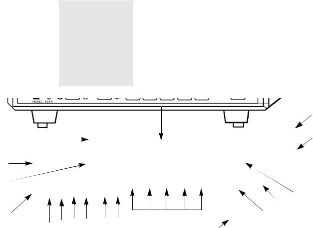
6 Rear & Top Panels
1 |
2 |
3 |
4 |
5 |
7 |
6 |
9
|
|
|
10 |
|
|
|
|
8 |
|
|
11 |
|
|||
|
|
|
1.Line Cord Clip; This clip can be set around the line cord strain relief so that the cord cannot be pulled out of the connector.
2.Line Cord Connector; The AC (Mains) line cord attaches to the monitor here.
3.Fuse Compartment; The AC (Mains) line fuse(s) are inside this compartment. Pry open with small screwdriver.
4.AC Mains Voltage; The currently selected AC Mains input voltage is identified here.
5.AC Mains Power Switch; With switch in “O” position, AC Mains voltage does not enter monitor. With switch in “|” position, AC Mains voltage allowed into monitor to power unit and/or charge internal battery.
6.Rear Feet; Rubber tipped rear feet
(2).
7.Serial Output Connector; Serial (RS232) data output here
for use with Tele-Sat™ telemetry system, optional analog output module, and other RS232 interfaces. A female 25-
pin “D” connector serves as the interface connector.
8.Top Cover
9.Carrying Handle; Monitor carrying handle molded into case.
10.Warning Label; Explosion and electrical shock warnings.
11.Patient Isolation Label; The Model 520A is Type BF equipment.
Figure 2. Rear and Top Panel Descriptions
5-Jun-01 |
Model 520A Service Manual 7 |

7 Summary of
Operation
This section summarizes the operation of the Model 520A Pulse Oximeter. It is intended as a quick reference and refresher for persons who have thoroughly reviewed the Model 520A User’s Manual (PN: 5693-23). Persons unfamiliar with the Model 520A should thoroughly examine the User’s Manual before referencing the steps listed here.
1.If powering the monitor from the AC line voltage; Connect the line cord to the monitor and plug into a properly grounded 3-wire outlet. Set the rear panel power (Mains) switch to the | (on) position.
2.Press the front panel POWER key to turn the monitor on. Verify the Message Center displays Connect SPO2 Probe after the self-tests are complete.
3.Use the Menu System to modify the operation of the monitor to best suit your application. The Menu System menus include:
•ALRT softkey - Use SEL to select SpO2 or Pulse limits, then use the ↑ or ↓ to set the limit to the desired value. Note that the monitor will maintain a spread of at least 5 digits between the upper and lower limit values.
•TRND softkey - enters Trend mode and draws trend memory on display.
•MENU then AUDIO softkeys - Select Pulse to turn on/off and control the
volume of the audible beep with each detected pulse. Select ALERT to control alert volume.
• MENU then AVG - Select either 2 second or 8 second SpO2 averaging time.
•MENU then LITE softkeys - toggles backlight between bright and dim.
4.Verify that the SpO2 and Pulse Rate alert limit settings are consistent with your monitoring application.
5.Connect a SuperBright™ (87xx series) sensor to the front panel input. Apply the sensor to the patient.
6.Check that within several seconds the patient’s SpO2 and Pulse Rate are displayed on the monitor.
7.As necessary, refer to the appropriate sections within the User’s Manual for detailed operating instructions and explanations.
8 Model 520A Service Manual |
5693-90-01 |

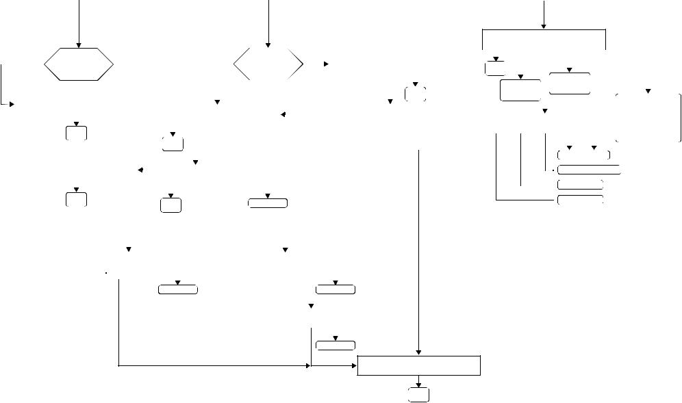
8 Menu Trees
The OXYPLETH menus are described on the following pages.
5-Jun-01 |
Model 520A Service Manual 9 |

POWER ON |
|
|
|
|
ERASE STORED TRENDS ? |
|
|||||
|
|
|
|
YES |
NO |
|
|||||
|
|
|
|
||||||||
|
|
|
|
|
|
||||||
|
|
|
|
|
|
|
|
|
|
|
|
|
|
|
|
|
|
|
|
|
|||
|
|
|
|
|
|
|
|
|
|
|
|
ERASING TREND PLEASE WAIT |
|
|
TREND RETAINED |
||||||||
|
|
|
|
|
|
|
|
|
|
|
|
|
|
|
|
|
|
|
|
|
|
|
|
|
|
|
|
|
|
|
|
|
|
|
|
TREND ERASED |
|
|
|
|
|
|
|
||||
|
|
|
|
|
|
|
|||||
|
|
|
|
|
|
|
|
|
|
|
|
|
|
|
|
SET ALERT LIMITS |
|
|
|
|
|
|
|
|
|
|
||||||
|
RUN |
SEL |
↑ |
↓ |
AUTO |
|
|
|
|
|
|
|||||||||
|
|
|
|
|
|
|
||||||||||||||
|
|
|
|
|
|
|
|
|
|
|
|
|
|
|
|
|
|
|||
|
|
|
|
|
|
|
|
|
|
|
|
|
||||||||
|
MAIN |
|
Will increase/decrease |
|
|
|||||||||||||||
|
MENU |
|
|
limits on selected |
|
|
||||||||||||||
|
|
|
|
|
|
parameter |
|
|
|
|
|
|
|
|
|
|
||||
|
|
|
|
|
|
|
|
|
|
|
|
|
|
|
|
|
|
|
||
|
Press to select Upper and |
|
|
|
|
|
|
|
|
|
|
|
|
|||||||
|
Lower Limits for Saturation |
|
|
|
|
|
|
|
|
|
|
|
|
|||||||
|
|
and Pulse Rate. |
|
|
|
|
|
|
|
|
|
|
|
|
|
|
|
|||
|
|
|
|
|
|
|
|
|
|
|
|
|
|
|
|
|
||||
|
|
|
|
|
|
|
|
|
|
|
|
|
|
|
|
|
|
|
|
|
|
|
|
|
|
|
|
yes |
|
|
Enough Data |
|
no |
|
|||||||
|
|
|
|
|
|
|
|
|
for Auto Limits |
|
|
|||||||||
|
|
|
|
|
|
|
|
|
|
|
|
|
|
|
||||||
|
|
|
|
|
|
|
|
|
|
|
? |
|
|
|
|
|
|
|||
|
|
|
|
|
|
|
|
|
|
|
|
|
|
|
|
|
|
|
|
|
|
|
|
|
|
|
|
|
|
|
|
|
|
|
|
|
|
|
|
|
|
|
|
AUTO ALERT LIMITS SET |
|
|
|
|
|
|
|
|
NOT ENOUGH DATA TO |
|
||||||||
|
|
|
|
|
|
|
|
|
|
|
|
|
|
|
|
|
SET AUTO LIMITS |
|
||
|
|
|
|
|
|
|
|
|
|
|
|
|
|
|
|
|
|
|||
|
|
|
|
|
|
|
|
|
|
|
|
|
|
|
|
|
|
|
|
|
|
|
|
|
|
|
|
|
|
|
|
|
|
|
|
|
|
|
|
|
|
|
|
|
|
MAIN |
|
|
|
|
|
|
|
|
|
|
|
|
|
|
|
|
|
|
|
|
MENU |
|
|
|
|
|
|
|
|
|
|
|
|
|
|
|
|
OXYPLETH™ Menu Tree
Revision 2.7 Software
7-Feb-97
MAIN MENU
message center
ALRT TRND |
MENU |
DRAWING TREND PLEASE WAIT
TREND |
MMMDD HH:MM:SS S |
P |
||
RUN |
EXPAN |
D |
<- |
-> |
Moves Cursor Left /
MAIN
MENU
Will change XX value XX= one of four settings: 12Hr, 8Hr, 2Hr, 30m
|
|
|
|
|
|
|
|
|
|
|
TREND OPTIONS: |
|
|
|
|
|
|
|
|
|
|
|
|
|
|
|
|
|
|
|
|
|
|
|
|
|
|
|
||||||||
|
|
|
|
|
|
|
|
RUN ERASE VIEW |
|
|
|
|
|
|
PREV |
|
|
|
|
Previous Menu |
|
|
|
|
|
|
|
|
|
|
|
|||||||||||||||
|
|
|
|
|
|
|
|
|
|
|
|
|
|
|
|
|
|
|
|
|
|
|
|
|
|
|
|
|
||||||||||||||||||
|
|
|
|
|
|
|
|
|
|
|
|
|
|
|
|
|
|
|
|
|
|
|
|
|
|
|
|
|
|
|
|
|
|
|
|
|
|
|
|
|||||||
|
|
|
|
|
|
|
|
MAIN |
|
|
|
|
|
|
|
|
|
|
|
|
|
|
|
|
|
|
|
|
|
|
|
|
|
|
|
|
|
|||||||||
|
|
|
|
|
|
|
|
|
|
|
|
|
|
|
|
|
|
|
|
|
|
|
|
|
|
|
|
|
|
|
|
|
|
|
|
|
||||||||||
|
|
|
|
|
|
|
|
|
|
|
|
|
|
|
|
|
|
|
|
|
|
|
|
|
|
|
|
|
|
|
|
|
|
|
|
|
|
|
|
|
|
|
|
|||
|
|
|
|
|
|
|
|
MENU |
|
|
|
|
|
|
|
|
|
|
|
|
|
|
|
|
|
|
|
|
|
|
|
|
|
|
|
|
|
|
|
|
|
|
|
|
||
|
|
|
|
|
|
|
|
|
|
|
|
|
|
|
|
|
|
|
|
|
|
|
|
|
|
|
|
|
|
|
|
|
|
|
|
|
|
|
|
|
|
|
|
|
||
|
|
|
|
|
|
|
|
|
|
|
|
|
|
|
|
|
|
|
|
|
|
|
|
|
|
|
|
|
|
|
|
|
|
|
|
|
|
|
|
|
|
|
|
|
|
|
|
|
|
|
|
*SCALE will appear only |
|
|
|
|
|
|
*SCALE |
|
|
|
TREND VIEW: |
|
|
|
|
|
|
|
|
|
|
|
|||||||||||||||||||
|
|
|
|
|
|
|
|
|
|
|
DUAL |
SpO2 |
HIST PREV |
|
|
|
|
|
|
|
||||||||||||||||||||||||||
|
|
|
|
|
|
|
|
|
|
|
|
|
|
|
|
|
|
|||||||||||||||||||||||||||||
|
|
|
|
|
|
|
when DUAL is selected |
|
|
|
|
|
|
|
|
|
|
|
|
|
|
|
|
|
|
|
|
|
|
|
|
|
|
|
|
|
|
|
|
|||||||
|
|
|
|
|
|
|
|
|
|
|
|
|
|
|
|
|
|
|
|
|
|
|
|
|
|
|
|
|
|
|
|
|
|
|
|
|
|
|
||||||||
|
|
|
|
|
|
|
from Trend View Options |
|
|
|
|
|
|
|
|
|
|
|
|
|
|
|
|
|
|
|
|
|
|
|
|
|
|
|
Previous Menu |
|||||||||||
|
|
|
|
|
|
|
|
|
|
|
|
|
|
|
|
|
|
|
|
|
|
|
|
|
|
|
|
|
|
|
|
|
|
|
|
|
|
|
|
|
|
|||||
|
ERASE STORED TRENDS ? |
|
|
|
|
|
|
|
|
|
|
|
|
|
|
|
|
|
|
|
|
|
|
|
|
|
|
|
|
|
|
|
|
|
|
|
|
|
|
|
|
|
|
|||
|
YES |
NO |
|
|
|
|
|
|
SPO2 |
PULSE |
|
|
|
|
|
|
|
|
|
|
|
|
|
|
|
|
|
|
|
Displays HISTOGRAM |
||||||||||||||||
|
|
|
|
|
|
|
|
|
|
|
|
|
|
|
|
|
|
|
|
|
|
|
|
|
||||||||||||||||||||||
|
|
|
|
|
|
|
|
|
|
|
|
|
|
|
|
|
|
|
|
|
|
|
|
|
|
|
|
|
|
|
|
|
|
|
|
|
|
|
|
|
|
|
||||
|
|
|
|
|
|
|
|
|
|
|
Select FULL or HALF |
|
|
|
|
|
|
|
|
|
|
|
|
|
|
|
|
|
|
|
|
|
|
|
|
|
|
|
||||||||
|
ERASING TRENDS PLEASE WAIT |
|
|
|
|
|
|
|
|
|
|
|
|
|
|
|
|
|
|
|
|
|
|
|
|
|
|
|
|
|
|
|
|
|
||||||||||||
|
|
|
|
|
|
|
|
|
|
|
|
|
|
|
|
|
|
|
|
|
|
|
|
|
|
|
|
|
|
|
|
|
|
|
|
|
|
|
|
|
|
|
|
|
|
|
|
|
|
|
|
|
|
|
|
|
|
|
|
|
|
|
|
|
|
|
|
|
|
|
|
|
|
|
|
|
|
|
|
|
|
|
|
|
|
|
|
|
|
|
|
|
|
|
|
|
|
|
|
|
|
|
|
|
|
|
|
DUAL XX HR |
|
|
|
|
|
|
|
|
|
|
|
|
|
|
|
|
SpO2 XX Hr |
|
|
|
|
|
|
|||||||||
|
|
|
|
|
|
|
|
|
RUN |
EXPAN |
D |
<- |
|
|
|
-> |
|
|
|
RUN |
EXPAN |
|
|
D |
<- |
-> |
|
|
||||||||||||||||||
|
|
|
|
|
|
|
|
|
|
|
||||||||||||||||||||||||||||||||||||
|
TRENDS ERASED |
|
|
|
|
|
|
|
|
|
|
|
|
|
|
|
|
|
|
|
|
|
|
|
|
|
|
|
|
|
|
|
|
|
|
|
|
|
|
|
|
|
|
|||
|
|
|
|
|
|
|
|
|
|
|
|
|
|
|
|
|
|
|
|
|
|
|
|
|
|
|
|
|
|
|
|
|
|
|
|
|
|
|
|
|
|
|||||
|
|
|
|
|
|
|
|
|
MAIN |
|
|
|
Moves Cursor Left/Right |
|
|
|
|
|
|
MAIN |
|
|
|
Moves Cursor Left/ |
|
|
|
|
||||||||||||||||||
|
|
|
|
|
|
|
|
|
|
|
|
|
|
|
|
|
|
|
|
|
|
|||||||||||||||||||||||||
|
|
|
|
|
|
|
|
|
MENU |
|
|
|
|
|
|
|
|
|
|
|
|
|
|
|
|
|
|
|
MENU |
|
|
|
|
|
|
|
|
|
|
|
|
|
|
|||
|
|
|
|
|
|
|
|
|
|
|
|
|
|
|
|
|
|
|
|
|
|
|
|
|
|
|
|
|
|
|
|
|
|
|
|
|
|
|
|
|
|
|
|
|
|
|
|
TREND RETAINED |
|
|
|
Will select one of four settings: |
|
|
|
|
|
|
|
|
|
|
Will select one of four settings: |
|
|
|
|
|
|
||||||||||||||||||||||||
|
|
|
|
|
|
|
|
|
|
12Hr, 8Hr, 2Hr, 30m |
|
|
|
|
|
|
|
|
|
|
|
|
12Hr, 8Hr, 2Hr, 30m |
|
|
|
|
|
|
|||||||||||||||||
|
|
|
|
|
|
|
|
|
|
|
|
|
|
|
|
|
|
|
|
|
|
|
|
|
|
|
|
|
|
|
|
|
|
|
|
|
|
|
|
|
|
|
|
|
|
|
|
|
|
|
|
|
|
|
|
|
|
|
|
|
|
|
|
|
|
|
|
|
|
|
|
|
|
|
|
|
|
|
|
|
|
|
|
|
|
|
|
|
|
|
|
|
|
OXYPLETH™ Menu Tree
Revision 2.7 Software
7-Feb-97
MAIN MENU
message center
ALRT TRND |
MENU |
*
SYSTEM OPTIONS |
IABP * |
|
RUN AUDIO LITE |
AVG |
|
IABPwill appear only if selected in SpO2 SETUP OPTIONS menu.
|
|
|
|
|
|
|
|
|
|
|
|
|
|
|
|
|
|
|
|
|
|
|
|
|
|
|
|
|
|
|
|
|
|
|
|
|
|
|
|
|
|
|
|
|
|
|
|
|
|
|
|
|
|
|
|
|
|
|
|
MAIN |
|
Toggles Back- |
|
|
|
|
|
|
|
|
|||
|
|
|
|
|
|
|
|
|
|
|
|
|
|
|
|
|
|
|
|
|
|
|
MENU |
|
|
light On/Off. |
|
|
|
|
SELECT IABP MODE |
|||||
|
|
|
|
|
|
|
|
|
|
|
SET AUDIO FEATURES |
|
|
|
|
|
|
|
|
|
|
|
|
|
|
|
|
ON |
OFF |
|||||||
|
|
|
|
|
|
|
|
|
|
|
|
|
|
|
|
|
|
|
|
|
|
|
|
|
|
|
|
|
|
|
|
|
||||
|
|
|
|
|
|
|
RUN |
PULSE ALERT |
PREV |
|
|
|
|
|
|
|
|
|
|
|
|
|
|
|
|
|
||||||||||
|
|
|
|
|
|
|
|
|
|
|
|
|
|
|
|
|
|
|
|
|
|
|
|
|
|
|
|
|
|
|
|
|
|
|
|
|
|
|
|
|
|
|
|
|
|
|
|
|
|
|
|
|
|
|
|
|
|
|
|
|
|
|
|
|
|
|
|
|
|
Activates IABP mode |
|||
|
|
|
|
|
|
|
MAIN |
|
|
|
|
Previous Menu |
|
|
|
|
|
|
|
|
||||||||||||||||
|
|
|
|
|
|
|
|
|
|
|
|
|
|
|
|
|
|
|
|
|
|
|
||||||||||||||
|
|
|
|
|
|
MENU |
|
|
|
|
|
|
|
|
|
|
|
|
|
|
|
|
|
|
|
|
|
|
|
|
|
|
||||
|
|
|
|
|
|
|
|
|
|
|
|
|
|
|
|
|
|
|
|
|
|
|
|
|
|
|
|
|
|
|
|
|
|
|
|
|
|
|
|
|
|
|
|
|
|
|
|
|
|
|
|
|
|
|
|
|
|
|
|
|
|
|
|
|
|
|
|
|
|
SELECT SPO2 AVERAGING |
|||
|
|
|
|
|
|
|
|
|
|
|
|
|
|
|
|
|
|
|
|
|
|
|
|
|
|
|
|
|
|
|
|
|
2s |
8s |
||
|
|
|
|
|
|
|
|
|
|
|
|
|
|
|
|
|
|
|
|
|
|
|
|
|
|
|
|
|
|
|
|
|
||||
|
|
|
|
|
|
|
|
|
|
|
|
|
|
|
|
|
|
|
|
|
|
|
|
|
|
|
|
|
|
|
|
|
|
|
|
|
|
|
SET PULSE VOLUME |
|
|
|
|
|
|
|
|
|
|
|
|
|
SET ALERT VOLUME |
|
|
|
|
|
|
|
|
|
|
|
|
||||||||
RUN |
|
↑ X X ↓ |
PREV |
|
|
|
|
|
|
RUN |
|
|
↑ X X ↓ |
PREV |
|
|
|
|
|
|
Select option |
|||||||||||||||
|
|
|
|
|
|
|
|
|
|
|
|
|
|
|
|
|
|
|
|
|
|
|
|
|
|
|
|
|
|
|
|
|
||||
|
|
|
|
|
|
|
|
|
|
|
|
|
|
|
|
|
|
|
|
|
|
|
|
|
|
|
|
|
|
|
|
|
||||
MAIN |
|
|
|
Previous Menu |
|
|
|
|
MAIN |
|
|
|
|
|
|
|
Previous Menu |
|
|
|
|
|||||||||||||||
MENU |
|
|
|
|
|
|
|
|
|
|
|
|
|
MENU |
|
|
|
|
|
|
|
|
|
|
|
|
|
|
|
|
|
|
|
|
||
|
|
Varies volume where |
|
|
|
|
|
|
|
|
|
|
|
|
Varies volume where |
|
|
|
|
|
|
|
|
|
|
|
|
|||||||||
|
|
XX=00 through 07 |
|
|
|
|
|
|
|
|
|
|
|
|
XX=00 through 07 |
|
|
|
|
|
|
|
|
|
|
|
|
|||||||||
message center |
|
|
message center |
|
message center |
||
ALRT TRND SIZE |
MENU |
|
ALRT TRND |
PRNT MENU |
|
ALRT TRND |
CARD MENU |
|
|
|
|
|
|
|
|
WAVEFORM AUTO SIZE must be turned ON in the SPO2 SETUP OPTIONS menu.
A serial printer interface must be selected in MONITOR OPTIONS 2 menu.
*The NOVACARD option must be programmed in MONITOR OPTIONS 2 menu.
NOVACARD MENU
RUN STORE ID ERASE TIME
|
no |
|
|
|
|
yes |
|
|
|
|
no |
|
|
|
|
|
|
yes |
PRINT IN PROGRESS |
|||||||||||
|
|
Signal present |
|
|
|
|
|
Printing in |
||||||||||||||||||||||
|
|
|
for resizing? |
|
|
|
|
|
|
|
|
|
|
|
|
|
|
|
progress? |
|
|
|
STOP CONT |
|||||||
|
|
|
|
|
|
|
|
|
|
|
|
|
|
|
|
|
|
|
|
|
|
|
|
|
|
|
|
|
|
|
|
|
|
|
|
|
|
|
|
|
|
|
|
|
|
|
|
|
|
|
|
|
|
|
|
|
|
|
|
|
|
|
|
|
|
|
|
|
|
|
|
|
|
|
|
|
|
|
|
|
|
|
|
|
|
|
|
|
|
|
|
|
|
|
|
|
|
|
|
|
|
|
|
|
|
|
|
|
|
|
|
|
|
|
|
|
|
|
|
|
|
|
|
|
|
|
|
|
|
|
|
|
|
|
|
|
|
|
|
|
|
|
|
|
|
|
|
|
|
|
|
MAIN |
||
|
|
CANNOT RESIZE SIGNAL |
|
|
|
|
|
|
|
|
|
|
|
|
|
|
|
|
|
|
|
|
|
|
MENU |
|||||
|
|
|
|
|
|
|
|
|
|
|
|
|
|
|
|
|
|
|
|
|
|
|
|
|
|
|
|
|
|
|
|
|
|
|
|
|
|
|
|
|
|
|
|
SELECT PRINT OPTIONS |
|
|
|
|
|
TERMINATING PRINTOUT |
|||||||||||
|
|
|
|
|
|
|
|
|
|
|
RUN |
TRND |
TAB |
WAVE |
|
|
|
|
|
|
|
|
|
|||||||
|
|
|
|
|
|
|
|
|
|
|
|
|
|
|
|
|
|
|
|
|||||||||||
|
|
|
MAIN |
|
|
|
|
|
|
|
|
|
|
|
|
|
|
|
|
|
|
|
|
|
|
|
|
|
||
|
|
|
|
|
|
|
|
|
|
|
|
|
|
|
|
|
|
|
|
|
|
|
|
|
|
|
|
|||
|
|
|
MENU |
|
|
|
|
|
MAIN |
|
|
|
|
|
|
|
|
|
|
|
|
|
|
|
|
|
|
|||
|
|
|
|
|
|
|
|
|
|
|
|
|
|
|
|
|
|
|
|
|
|
|
|
|
|
|
|
|
||
|
|
|
|
|
|
|
|
|
|
|
MENU |
|
|
|
|
|
|
|
|
|
|
|
|
|
|
|
|
|
|
|
|
|
|
|
|
|
|
|
|
|
|
|
|
|
|
|
|
|
|
|
|
|
|
|
|
|
|
|
|
|
|
|
|
RESIZING PLETH |
|
|
|
|
|
|
|
|
|
|
|
|
|
|
|
|
|
|
|
|
|
|
|
|
|
|||
|
|
|
|
|
|
|
|
|
|
|
|
|
|
PRINT TREND |
|
|
|
|
|
|
|
|
|
|||||||
|
|
|
|
|
|
|
|
|
|
|
RUN |
ALL |
PART |
|
|
PREV |
|
|
|
|
|
|
|
|
|
|||||
|
|
|
|
|
|
|
|
|
|
|
|
|
|
|
|
|
|
|
|
|
|
|
|
|
|
|
|
|
|
|
|
|
|
MAIN |
|
|
|
|
|
|
|
|
|
|
|
|
|
|
|
|
|
|
|
|
|
|
|
|
|
||
|
|
|
|
|
|
|
|
|
|
|
|
|
|
|
|
|
|
|
|
|
|
|
|
|
|
|
|
|||
|
|
|
MENU |
|
|
|
|
|
MAIN |
|
|
|
|
|
|
Previous Menu |
|
|
|
|
|
|
|
|||||||
|
|
|
|
|
|
|
|
|
|
|
MENU |
|
|
|
|
|
|
|
|
|
|
|
|
|
|
|
|
|
|
|
|
|
|
|
|
|
|
|
|
|
|
|
|
|
|
|
|
|
|
|
|
|
|
|
|
|
|
|
|
|
|
|
|
|
|
|
|
|
|
|
|
|
|
|
|
|
|
|
|
|
|
|
|
|
|
|
|
|
|
|
|
|
|
SELECT PRINT COMPRESSION |
|
|
SET START - XX : XX |
|
|
|
||||||||||
NONE |
1/2 |
1/4 |
PAGE PREV |
|
RESET |
↑ |
↓ |
ENTER |
PREV |
|
|||||||
|
|
|
|
|
|
|
|
|
|
|
|
|
|
|
|
|
|
|
|
|
|
|
|
|
|
|
|
|
|
|
|
|
|||
|
|
|
|
|
|
|
Previous Menu |
|
|
|
|
Previous Menu |
|||||
|
|
|
|
|
|
|
|
|
|
|
|
|
|
|
|
||
|
|
|
|
|
|
|
|
|
|
|
|
|
|
|
|
|
|
|
|
|
|
|
|
|
|
|
|
|
SET STOP - XX : XX |
|
|
|
|||
|
|
|
|
|
|
|
|
|
|
RESET |
↑ |
↓ |
PREV |
|
|||
|
|
|
|
|
|
|
|
|
|
|
|
|
|
|
|
|
|
|
|
|
|
|
|
|
|
|
|
|
|
|
|
|
|
||
|
|
|
|
|
|
|
|
|
|
|
|
|
|
Previous Menu |
|||
|
|
|
|
|
|
|
|
|
|
|
|
MAIN |
|
|
|
|
|
|
|
|
|
|
|
|
|
|
|
|
|
|
|
|
|
||
MENU |
|
|
|
|
Erases info in |
|
|
|
|
||
|
|
Stores info to |
|
|
|
|
|
|
|||
|
|
|
|
NOVACARD |
|
|
|
|
|||
|
|
NOVACARD |
|
|
module |
|
|
|
|
||
|
|
module |
|
|
|
|
|
|
SELECTS: FROM LAST |
||
|
|
|
|
|
|
|
|
|
|
||
|
|
|
|
|
|
|
|
|
|
LAST 30 MINS |
|
|
|
|
|
|
|
|
|
|
|
|
LAST 1 HR |
|
|
|
|
|
|
|
|
|
|
LAST 2 HRS |
|
|
|
PATIENT ID: _ _ _ _ _ _ _ _ _ |
|
|
LAST 4 HRS |
||||||
|
|
|
|
|
|
↑ |
↓ |
||||
SET |
CLR |
SEL |
LAST 8 HRS |
||||||||
|
|
|
|
|
|
|
|
|
|
LAST 12 HRS |
|
|
|
|
|
|
|
|
|
|
|
LAST 24 HRS |
|
|
|
|
|
|
|
|
|
|
|
|
|
Sequences from 0-9

 Selects ID fields from 1-9
 Clears patient ID
 Accepts patient ID
*PRINT and SIZE will appear only if selected in the setup menu. CARD will appear if NOVACARD interface is selected.
PRINTOUT STARTED
MAIN
MENU
OXYPLETH™ Menu Tree
Revision 2.7 Software 7-Feb-97

OXYPLETH™ Menu Tree
Revision 2.7 Software
7-Feb-97
message center
ALRT TRND |
MENU |
Press and hold MENU key for 5 seconds
|
SPO2 SETUP OPTIONS |
|
|
|
|
|
|
|
|
|
|
|
|
|
SPO2 TIMERS |
|
|
|
|
|
|
|
|
|
|
|
|
|||||||||||
RUN MODE IABP |
SIZE NEXT |
|
|
|
|
|
|
|
|
|
|
|
RUN HELD SPEC BAD NEXT |
|
|
|
|
|
|
|
|
|
|
|
|
|||||||||||||
|
|
|
|
|
|
|
|
|
|
|
|
|
|
|
|
|
|
|
|
|
|
|
||||||||||||||||
|
|
|
|
|
|
|
|
|
|
|
|
|
|
|
|
|
|
|
|
|
|
|
|
|
|
|
|
|
|
|
|
|
|
|
|
|
|
|
|
|
|
|
|
|
|
|
|
|
|
|
|
|
|
|
|
|
|
|
|
|
|
|
|
|
|
|
|
|
|
|
|
|
|
|
|
|
|
MAIN |
|
|
|
|
|
|
|
|
|
|
|
|
|
|
|
|
|
MAIN |
|
|
|
|
|
|
|
|
|
|
|
|
|
|
|
|
|
|
||
|
|
|
|
|
|
|
|
|
|
|
|
|
|
|
|
|
|
|
|
|
|
|
|
|
|
|
|
|
|
|
|
|
|
|
||||
MENU |
|
|
|
|
|
|
|
|
|
|
|
|
|
|
|
|
|
MENU |
|
|
|
|
|
|
|
|
|
|
|
|
|
|
|
|
|
|||
|
|
|
|
|
|
|
|
|
|
|
|
|
|
|
|
|
|
|
|
|
|
|
|
|
|
|
|
|
|
|
|
|
|
|
|
|||
|
|
|
|
|
|
|
|
|
|
WAVEFORM AUTO SIZE |
|
|
|
|
|
|
|
|
|
|
|
|
|
ALERT ON BAD SIGNAL |
|
|
|
|||||||||||
|
|
|
|
|
|
|
|
|
|
ON |
OFF |
|
|
|
|
|
|
|
|
|
|
|
|
|
ON |
OFF |
|
|
|
|
|
|||||||
|
|
|
|
|
|
|
|
|
|
|
|
|
|
|
|
|
|
|
|
|
|
|
|
|
|
|
|
|||||||||||
|
|
|
|
|
|
|
|
|
|
|
|
|
|
|
|
|
|
|
|
|
|
|
|
|
|
|
|
|
|
|
|
|
|
|||||
|
|
|
|
|
|
|
|
|
|
|
|
|
|
|
|
|
|
|
|
|
|
|
|
|
|
|
|
|
|
|
|
|
|
|||||
|
|
|
|
|
|
|
|
|
Select the option to have the |
|
|
|
|
|
|
|
|
|
|
|
|
Selects the display held timer |
|
|
|
|||||||||||||
|
|
|
|
|
|
|
|
|
Pleth waveform automatically |
|
|
|
|
|
|
|
|
|
|
|
|
|
|
|
option |
|
|
|
|
|
||||||||
|
|
|
|
|
|
|
|
|
scaled to fit in the display |
|
|
|
|
|
|
|
|
|
|
|
|
|
|
|
|
|
|
|
|
|||||||||
|
|
|
|
|
|
|
|
|
|
|
|
|
|
|
|
|
|
|
|
|
|
|
|
|
|
|
|
|
|
|
|
|||||||
|
|
|
|
|
|
|
|
|
window |
|
|
|
|
|
|
|
|
|
|
|
|
|
|
|
|
|
|
|
|
|
|
|
|
|
|
|
||
|
|
|
|
|
|
|
|
|
|
|
|
|
|
|
|
|
|
|
|
|
|
|
|
|
|
|
|
|
|
|
|
|
|
|
|
|||
|
|
|
|
|
|
|
|
|
|
IABP MODE AVAILABLE ? |
|
|
|
|
|
|
|
|
|
|
|
|
|
SPECIAL ALERT DELAY |
|
|
|
|||||||||||
|
|
|
|
|
|
|
|
|
|
YES |
NO |
|
|
|
|
|
|
|
|
|
|
|
15s |
30s |
45s |
60s |
90s |
|||||||||||
|
|
|
|
|
|
|
|
|
|
|
|
|
|
|
|
|
|
|
|
|
||||||||||||||||||
|
|
|
|
|
|
|
|
|
|
|
|
|
|
|
|
|
|
|
|
|
||||||||||||||||||
|
|
|
|
|
|
|
|
|
|
|
|
|
|
|
|
|
|
|
|
|
|
|
|
|
|
|
|
|
|
|
|
|
|
|
||||
|
|
|
|
|
|
|
|
|
|
|
|
|
|
|
|
|
|
|
|
|
|
|
|
|
|
|
|
|
|
|
|
|
||||||
|
|
|
|
|
|
|
|
|
Allows IABP mode, if selected |
|
|
|
|
|
|
|
|
|
|
|
|
|
Selects the special alert delay time, |
|
|
|
||||||||||||
|
|
|
|
|
|
|
|
|
the IABP softkey will appear |
|
|
|
|
|
|
|
|
|
|
|
|
|
current selection will flash |
|
|
|
||||||||||||
|
|
|
|
|
|
|
|
|
in |
the SYSTEM OPTIONS |
|
|
|
|
|
|
|
|
|
|
|
|
|
|
|
|
|
|
|
|
|
|
|
|||||
|
|
|
|
|
|
|
|
|
|
|
|
|
|
|
|
|
|
|
|
|
|
|
|
|
|
|
|
|
|
|
|
|
|
|
|
|
|
|
|
|
|
|
|
|
|
|
|
|
SELECT OPERATING MODE |
|
|
|
|
|
|
|
|
|
|
|
|
|
DISPLAY HELD TIMER |
|
|
|
|||||||||||
|
|
|
|
|
|
|
|
|
|
|
|
|
|
|
|
|
|
|
|
|
|
|
|
|
|
|
|
|
|
|
|
|||||||
|
|
|
|
|
|
|
NICU |
ICU |
ANST SLEEP |
PREV |
|
|
|
|
|
|
|
|
0s |
15s |
30s |
60s |
|
|
|
|||||||||||||
|
|
|
|
|
|
|
|
|
|
|
|
|
|
|
|
|
|
|||||||||||||||||||||
|
|
|
|
|
|
|
|
|
|
|
|
|
|
|
|
|
|
|
|
|
|
|
|
|
|
|
|
|
|
|||||||||
|
|
|
|
|
|
|
|
|
|
|
|
|
|
|
|
|
|
|
|
|
|
|
|
|
|
|
|
|
|
|
|
|
|
|
|
|
|
|
|
|
|
|
|
|
|
|
|
|
|
|
|
|
|
|
|
|
|
|
|
|
|
|
|
|
|
|
|
|
|
||||||||
|
|
|
|
|
|
|
|
|
|
|
|
|
|
|
Previous Menu |
|
|
|
|
|
|
|
|
|
|
|
|
|||||||||||
|
|
|
|
|
|
|
|
|
|
|
|
|
|
|
Selects the alert on bad signal |
|
|
|
||||||||||||||||||||
|
|
|
|
|
|
|
|
|
|
Select desired mode |
|
|
|
|
|
|
|
|
|
|
|
|
|
|
||||||||||||||
|
|
|
|
|
|
|
|
|
|
|
|
|
|
|
|
|
|
|
|
|
time, current selection will flash |
|
|
|
||||||||||||||
|
|
MONITOR OPTIONS 1 |
|
|
|
|
|
|
||||||
RUN |
DISP KLCK VER NEXT |
|
|
|
|
|
|
|||||||
|
|
|
|
|
|
|
|
|
|
|
|
Continued |
||
|
|
|
|
|
|
|
|
|
|
|
|
|||
|
|
|
|
|
|
|
|
|
|
|
|
|||
MAIN |
|
|
Displays |
|
|
next page |
||||||||
MENU |
|
|
|
|
|
|
|
|
||||||
|
|
Current Revision |
|
|
|
|
|
|
||||||
|
Inverts display |
|
|
|
|
|
|
|||||||
|
|
|
|
|
|
|
|
|
|
|
||||
|
|
color |
|
|
|
|
SET KEYCLICK VOLUME |
|||||||
|
|
|
|
|
|
|
RUN |
|
↑ X X ↓ |
PREV |
||||
|
|
|
|
|
|
|
||||||||
|
|
|
|
|
|
|
|
|
|
|
|
|
|
|
|
|
|
|
|
|
|
|
|
|
|
|
|
|
|
|
|
|
|
|
|
|
MAIN |
Varies volume |
Previous Menu |
|||||
|
|
|
|
|
|
|
MENU |
|
from 00-07 |
|
|
|||

From previous page
|
|
MONITOR OPTIONS 2 |
|
|
|
|
|
|
|
|
|
|
|
|
|
|
|
|
|
|
ALERT OPTIONS 1 |
|
|
|
|
|
|
|
|
|
|
|
|
||||||||||||||
RUN |
SER CLOCK REC NEXT |
|
|
|
|
|
|
|
|
|
|
|
|
|
RUN LATCH DFLT |
MUTE |
|
NEXT |
|
|
|
|
|
|
|
|
|||||||||||||||||||||
|
|
|
|
|
|
|
|
|
|
|
|
|
|
|
|
|
|
|
|
|
|
||||||||||||||||||||||||||
|
|
|
|
|
|
|
|
|
|
|
|
|
|
|
|
|
|
|
|
|
|
|
|
|
|
|
|
|
|
|
|
|
|
|
|
|
|
|
|
|
|
|
|
|
|
|
|
|
|
|
|
|
|
|
|
|
|
|
|
|
|
|
|
|
|
|
|
|
|
|
|
|
|
|
|
|
|
|
|
|
|
|
|
|
|
|
|
|
|
|
|
|
|||
MAIN |
|
|
|
|
|
|
|
|
|
|
|
|
|
|
|
|
|
|
|
|
|
|
MAIN |
|
|
|
|
|
|
|
|
|
|
|
|
|
|
|
|
|
|
|
|||||
|
|
|
|
|
|
|
|
|
|
|
|
|
|
|
|
|
|
|
|
|
|
|
|
|
|
|
|
|
|
|
|
|
|
|
|
|
|
|
|
||||||||
MENU |
|
|
|
|
|
|
|
|
|
|
|
|
|
|
|
|
|
|
|
|
|
|
MENU |
|
|
|
|
|
|
|
|
|
|
|
|
|
|
|
|
|
|
||||||
|
|
|
|
|
|
|
|
|
|
|
|
|
CALIBRATE RECORDER |
|
|
|
|
|
|
|
|
|
|
|
|
|
|
|
|
|
|
|
|
|
|
ALLOW AUDIO OFF |
|||||||||||
|
|
|
|
|
|
|
|
RUN |
|
ZERO |
HALF |
FULL |
PREV |
|
|
|
|
|
|
|
|
|
|
|
|
|
|
|
|
|
|
|
YES |
NO |
|||||||||||||
|
|
|
|
|
|
|
|
|
|
|
|
|
|
|
|
|
|
|
|
|
|
|
|
|
|
|
|
|
|||||||||||||||||||
|
|
|
|
|
|
|
|
|
|
|
|
|
|
|
|
|
|
|
|
|
|
|
|
|
|
|
|
||||||||||||||||||||
|
|
|
|
|
|
|
|
|
|
|
|
|
|
|
|
|
|
|
|
|
|
|
|
|
|
|
|
|
|
|
|
|
|
|
|
|
|
|
|
|
|
|
|
|
|
|
|
|
|
|
|
|
|
|
|
|
|
|
|
|
|
|
|
|
|
|
|
|
|
|
|
|
|
|
|
|
|
|
|
|
|
|
|
|
|
|
|
|
|
|
|
|
|
|
|
|
|
|
|
|
|
|
MAIN |
|
|
|
|
|
|
|
Previous Menu |
|
|
|
|
|
|
|
|
|
|
|
|
|
|
|
|
|
|
Select option |
|||||||||||||
|
|
|
|
|
|
|
MENU |
|
|
|
|
|
|
|
|
|
|
|
|
|
|
|
|
|
|
|
|
|
|
|
|
|
|||||||||||||||
|
|
|
|
|
|
|
|
|
|
|
|
|
|
|
|
|
|
|
|
|
|
|
|
|
|
|
|
|
|
|
|
||||||||||||||||
|
|
|
|
|
|
|
|
|
|
|
|
Sets output of Analog Module to |
|
|
|
|
|
|
|
|
|
|
|
|
|
|
|
|
|
|
|
|
|
|
|
|
|
|
|
|
|||||||
|
|
|
|
|
|
|
|
|
|
|
|
|
respective values: 0-.5-1V |
|
|
|
|
|
|
|
|
|
|
|
|
|
|
|
|
|
|
|
|
|
|
|
|
|
|
|
|
||||||
|
|
|
|
|
|
|
|
|
|
|
|
|
|
|
|
|
|
|
|
|
|
|
|
|
|
|
|
|
|
|
|
|
|
RETAIN ALERT LIMITS |
|||||||||||||
|
|
|
|
|
|
|
|
|
|
|
|
|
|
|
|
|
|
|
|
|
|
|
|
|
|
|
|
|
|
|
|
|
|
|
|
|
|
|
|
|
|
||||||
|
|
|
|
|
|
|
|
|
|
|
|
|
|
|
|
|
|
|
|
|
|
|
|
|
|
|
|
|
|
|
|
|
|
|
|
|
|
|
|
|
|
YES |
NO |
||||
|
|
|
|
|
|
|
|
|
|
|
|
|
|
|
|
|
|
|
|
|
|
|
|
|
|
|
|
|
|
|
|
|
|
|
|
|
|
|
|
|
|
||||||
|
|
|
|
|
|
|
|
|
|
|
|
|
HH : MM DD/MMM / YY |
|
|
|
|
|
|
|
|
|
|
|
|
|
|
|
|
|
|
|
|
|
|
||||||||||||
|
|
|
|
|
|
|
|
|
|
|
|
|
|
|
|
|
|
|
|
|
|
|
|
|
|
|
|
|
|
|
|
|
|
|
|
|
|
|
|
|
|||||||
|
|
|
|
|
|
|
|
SET |
|
SEL |
↑ |
↓ |
|
|
|
|
|
|
|
|
|
|
|
|
|
|
|
|
|
|
|
|
|
|
|
|
|
|
|
|
|||||||
|
|
|
|
|
|
|
|
|
|
|
|
|
|
|
|
|
|
|
|
|
|
|
|
|
|
|
|
|
|
Select option |
|||||||||||||||||
|
|
|
|
|
|
|
|
|
|
|
|
|
|
|
|
|
|
|
|
|
|
|
|
|
|
|
|
|
|
|
|
|
|
|
|
|
|
|
|
|
|
||||||
|
|
|
|
|
|
|
|
|
|
|
|
|
|
|
|
|
|
|
|
|
|
|
|
|
|
|
|
|
|
|
|
|
|
|
|
|
|
|
|
|
|
||||||
|
|
|
|
|
|
|
|
Use SEL to select parameter, set |
|
|
|
|
|
|
|
|
|
|
|
|
|
|
|
|
|
|
|
|
|
|
|
|
|
|
|
|
|||||||||||
|
|
|
|
|
|
|
|
value with arrow keys. Press SET |
|
|
|
|
|
|
|
|
|
|
|
|
|
|
|
|
|
|
|
|
|
|
ALERTS LATCHED |
||||||||||||||||
|
|
|
|
|
|
|
|
|
|
|
|
to Accept changes |
|
|
|
|
|
|
|
|
|
|
|
|
|
|
|
|
|
|
|
|
|
|
|
|
YES |
NO |
|||||||||
|
|
|
|
|
|
|
|
|
|
|
|
|
|
|
|
|
|
|
|
|
|
|
|
|
|
|
|
|
|
|
|
|
|
|
|
||||||||||||
|
|
|
|
|
|
|
|
|
|
|
|
|
|
|
|
|
|
|
|
|
|
|
|
|
|
|
|
|
|
|
|
|
|
|
|
|
|
|
|
|
|
||||||
|
|
|
|
|
|
|
|
|
|
|
|
|
|
|
|
|
|
|
|
|
|
|
|
|
|
|
|
|
|
|
|
|
|
|
|
|
|
|
|
|
|
|
|
|
|
||
|
|
|
|
|
|
|
|
|
|
|
|
|
FULL FORMAT MODE |
|
|
|
|
|
|
|
|
|
|
|
|
|
|
|
|
|
|
|
|
|
|
|
|
|
|
|
|
||||||
|
|
|
|
|
|
|
|
|
|
|
|
|
|
|
|
|
|
|
|
|
|
|
|
|
|
|
|
|
|
|
|
|
|
|
|
|
|
|
|
||||||||
|
|
|
|
|
|
|
|
SET |
|
|
|
|
|
|
PREV |
NEXT |
|
|
|
|
|
|
|
|
|
|
|
|
|
|
|
|
|
|
|
Select option |
|||||||||||
|
|
|
|
|
|
|
|
|
|
|
|
|
|
|
|
|
|
|
|
|
|
|
|
|
|
|
|
|
|
|
|
|
|
||||||||||||||
|
|
|
|
|
|
|
|
|
|
|
|
|
|
|
|
|
|
|
|
|
|
|
|
|
|
|
|
|
|
|
|
|
|
|
|
|
|
|
|
|
|
|
|
|
|||
|
|
|
|
|
|
|
|
|
|
|
|
|
|
|
|
|
|
|
|
|
|
|
|
|
|
|
|
|
SELECT BAUD RATE = 1200 |
|
|
|
|
|
|
|
|
||||||||||
|
|
|
|
|
|
|
|
|
|
|
|
|
|
|
|
|
|
|
|
|
|
|
|
|
|
|
SET |
|
|
|
PREV |
NEXT |
|
|
|
|
|
|
|||||||||
|
|
|
|
|
|
|
|
|
|
|
|
|
|
|
|
|
|
|
|
|
|
|
|
|
|
|
|
|
|
|
|
|
|
|
|
||||||||||||
|
|
|
|
|
|
|
|
|
|
|
|
|
|
|
|
|
|
|
|
|
|
|
|
|
|
|
|
|
|
|
|
|
|
|
|
|
|
|
|
|
|
|
|
|
|
||
|
|
|
|
|
|
|
|
|
|
|
|
|
SARACAP INTERFACE |
|
|
|
|
|
|
|
|
|
|
|
|
|
|
|
|
|
|
|
|
|
|
|
|
|
|
|
|
||||||
|
|
|
|
|
|
|
|
SET |
|
|
|
|
|
|
PREV |
NEXT |
|
|
|
|
|
|
|
|
|
|
|
|
|
|
|
|
|
|
|
|
|
|
|
|
|
||||||
|
|
|
|
|
|
|
|
|
|
|
|
|
|
|
|
|
|
|
|
|
|
|
|
|
|
|
|
|
|
|
|
|
|
|
|
|
|
|
|||||||||
|
|
|
|
|
|
|
|
|
|
|
|
|
Selects SARACAP Interface |
|
|
|
|
|
|
|
|
|
|
SELECT PARITY = NONE |
|
|
|
|
|
|
|
|
|||||||||||||||
|
|
|
|
|
|
|
|
|
|
|
|
|
|
|
|
|
|
|
|
SET |
|
|
|
PREV |
NEXT |
|
|
|
|
|
|
||||||||||||||||
|
|
|
|
|
|
|
|
|
|
|
|
|
|
|
|
|
|
|
|
|
|
|
|
|
|
|
|
|
|||||||||||||||||||
|
|
|
|
|
|
|
|
|
|
|
|
|
|
|
|
|
|
|
|
|
|
|
|
|
|
|
|
|
|
|
|
|
|
|
|
|
|
|
|
|
|
|
|
|
|
||
|
|
|
|
|
|
|
|
|
|
|
|
|
1260/1010 INTERFACE |
|
|
|
|
|
|
|
|
|
|
|
|
|
|
|
|
|
|
|
|
|
|
|
|
|
|
|
|
||||||
|
|
|
|
|
|
|
|
SET |
|
|
|
|
|
|
PREV |
NEXT |
|
|
|
|
|
|
|
|
|
|
|
|
|
|
|
|
|
|
|
|
|
|
|
|
|
||||||
|
|
|
|
|
|
|
|
|
|
|
|
|
|
|
|
|
|
|
|
|
|
|
|
|
|
|
|
|
|
SELECT DATA BITS = 8 |
|
|
|
|
|
|
|
|
|||||||||
|
|
|
|
|
|
|
|
|
|
|
|
|
Selects 1260/1010 Interface |
|
|
|
|
|
|
|
SET |
|
|
|
PREV |
NEXT |
|
|
|
|
|
|
|||||||||||||||
|
|
|
|
|
|
|
|
|
|
|
|
|
|
|
|
|
|
|
|
|
|
|
|
|
|
|
|
|
|||||||||||||||||||
|
|
|
|
|
|
|
|
|
|
|
|
|
|
|
|
|
|
|
|
|
|
|
|
|
|
|
|
|
|
|
|
|
|
|
|
|
|
|
|
|
|
|
|
|
|
||
|
|
|
|
|
|
|
|
|
|
|
|
|
INTERFACE UNUSED |
|
|
|
|
|
|
|
|
|
|
|
|
|
|
|
|
|
|
|
|
|
|
|
|
|
|
|
|
||||||
|
|
|
|
|
|
|
|
SET |
|
|
|
|
|
|
PREV |
NEXT |
|
|
|
|
|
|
|
|
|
|
|
|
|
|
|
|
|
|
|
|
|
|
|
|
|
||||||
|
|
|
|
|
|
|
|
|
|
|
|
|
|
|
|
|
|
|
SELECT STOP BITS = 1 |
|
|
|
|
|
|
|
|
||||||||||||||||||||
|
|
|
|
|
|
|
|
|
|
|
|
|
|
|
|
|
|
|
|
|
|
|
|
|
|
|
|
|
|
|
|
|
|
|
|
|
|
||||||||||
|
|
|
|
|
|
|
|
|
|
|
|
|
|
Selects NO Interface |
|
|
|
|
|
|
|
SET |
|
|
|
PREV |
NEXT |
|
|
|
|
|
|
||||||||||||||
|
|
|
|
|
|
|
|
|
|
|
|
|
|
|
|
|
|
|
|
|
|
|
|
|
|
|
|
|
|
|
|
|
|
|
|
|
|
|
|
|
|
||||||
|
|
|
|
|
|
|
|
|
|
|
|
|
|
|
|
|
|
|
|
|
|
|
|
|
|
|
|
|
|
|
|
|
|
|
|
|
|
|
|
||||||||
|
|
|
|
|
|
|
|
|
|
|
|
|
PRINTER INTERFACE |
|
|
|
|
|
|
|
|
|
|
Selects FULL FORMAT MODE Interface |
|
|
|
|
|||||||||||||||||||
|
|
|
|
|
|
|
|
|
|
|
|
|
|
|
|
|
|
|
|
|
|
|
|
|
|
|
|||||||||||||||||||||
|
|
|
|
|
|
|
|
SET |
|
|
|
|
|
|
PREV |
NEXT |
|
|
|
|
|
|
|
|
|
|
|
|
|
|
|
|
|
|
|
|
|
|
|
|
|
||||||
|
|
|
|
|
|
|
|
|
|
|
|
|
|
|
|
|
|
|
|
|
|
|
|
|
|
|
|
|
|
|
|
|
|
|
|
|
|
|
|
|
|
|
|
|
|||
|
|
|
|
|
|
|
|
|
|
|
|
|
|
|
|
|
|
|
|
|
|
|
|
|
|
|
|
|
|
SELECT PRINTER TYPE |
|
|
|
|
|
|
|
|
|||||||||
|
|
|
|
|
|
|
|
|
|
|
|
|
|
|
|
|
|
|
|
|
|
|
|
|
|
|
|
|
|
SEIKO |
TJET |
315 |
|
|
|
|
|
|
|
|
|
||||||
|
|
|
|
|
|
|
|
|
|
|
|
|
|
|
|
|
|
|
|
|
|
|
|
|
|
|
|
|
|
|
|
|
|
|
|
|
|
|
|||||||||
|
|
|
|
|
|
|
|
|
|
|
|
|
|
|
|
|
|
|
|
|
|
|
|
|
|
|
|
|
|
|
|
|
|
|
|
|
|
|
|
|
|
|
|
|
|
||
|
|
|
|
|
|
|
|
|
|
|
|
|
NOVACOM1 INTERFACE |
|
|
|
|
|
|
|
|
|
|
|
|
|
|
|
|
|
|
|
|
|
|
|
|
|
|
|
|
||||||
|
|
|
|
|
|
|
|
SET |
|
|
|
|
|
|
PREV |
NEXT |
|
|
|
|
|
|
|
|
|
|
Select option |
|
|
|
|
|
|
|
|
|
|
|
|
||||||||
|
|
|
|
|
|
|
|
|
|
|
|
|
|
|
|
|
|
|
|
|
|
|
|
|
|
|
|
|
|
|
|
|
|
|
|
|
|
|
|
|
|
|
|
||||
|
|
|
|
|
|
|
|
|
|
|
|
|
Selects NOVACOM1 Interface |
|
|
|
|
|
|
|
|
|
|
|
|
|
|
|
|
|
|
|
|
|
|
|
|
||||||||||
|
|
|
|
|
|
|
|
|
|
|
|
|
|
|
|
|
|
|
|
|
|
|
|
|
|
|
|
|
|
|
|
|
|
|
|
|
|||||||||||
|
|
|
|
|
|
|
|
|
|
|
|
|
|
|
|
|
|
|
|
|
|
|
|
|
|
|
|
|
|
|
|
|
|
|
|
|
|
|
|
|
|
|
|
|
|
||
|
|
|
|
|
|
|
|
|
|
|
|
|
NOVACARD INTERFACE |
|
|
|
|
|
|
|
|
|
|
|
|
|
|
|
|
|
|
|
|
|
|
|
|
|
|
|
|
||||||
|
|
|
|
|
|
|
|
SET |
|
|
|
|
|
|
PREV |
NEXT |
|
|
|
|
|
|
|
|
|
|
|
|
|
|
|
|
|
|
|
|
|
|
|
|
|||||||

 Selects NOVACARD Interface
|
|
|
ALERT OPTIONS 2 |
|
|
|
|
|
|||||
RUN |
DELAY BAR PREV NEXT |
|
|
|
|
|
|||||||
|
|
|
|
|
|
|
|
|
|
Displays SPO2 SETUP |
|||
|
|
|
|
|
|
|
|
|
|
||||
|
|
|
|
|
|
|
|
|
|
||||
MAIN |
|
|
Previous Menu |
|
|
OPTIONS menu |
|||||||
MENU |
|
|
|
|
|
|
|
|
|
|
|
|
|
|
|
|
|
|
|
|
|
|
|
|
|
|
|
|
|
|
|
|
|
|
|
ALERT BAR LATCHED |
|||||
|
|
|
|
|
|
|
|
YES |
NO |
OFF |
|||
|
|
|
|
|
|
|
|
||||||
|
|
|
|
|
|
|
|
|
|
|
|
|
|
|
|
|
|
|
|
|
|
|
|
|
|
|
|
|
|
|
|
|
|
|
|
|
|
Select option |
|||
|
|
|
|
|
|
|
|
|
|
|
|
|
|
|
|
|
|
|
|
|
10 SEC ALERT LIMIT DELAY |
||||||
|
|
|
|
|
|
|
|
YES |
NO |
|
|
||
|
|
|
|
|
|
|
|
|
|||||
|
|
|
|
|
|
|
|
|
|
|
|
|
|
|
|
|
|
|
|
|
|
|
|
|
|
|
|
Select option
OXYPLETH™ Menu Tree
Revision 2.7 Software
7-Feb-97

9 Electronic Theory
of Operation
The electronic theory of operation of the Model 520A Pulse Oximeter monitor is detailed in the subsections below. Refer to Section 19, Schematic and Assembly Drawings, on page 93 for further information.
2472 Power Supply Board |
9.1 |
The 2472 Power Supply Board contains the circuitry needed to power the monitor from the AC Mains (line voltage). The power supply board also connects to the battery and contains the battery charging circuitry.
AC Mains and Battery Operation Overview |
9.1.1 |
The Model 520A can be powered from its internal 12 volt battery or from the AC Mains. The green 

 (sine wave shaped) front panel indicator illuminates when the line cord is connected and the rear panel power switch is in the “|” (On) position. This indicates that AC Mains power is reaching the power supply, that the battery is being charged, and that if the monitor is turned on, it is being powered from the line voltage.
If AC Mains power is removed by unplugging the line cord or setting the rear panel power switch to the “0” (Off) position, the monitor will operate for up to four hours from its internal 12 volt lead-acid battery. As the battery voltage runs low (≈11.5 volts), the red 


 (battery indicator) on the front panel illuminates. At this point, the AC Mains should be reconnected to power the monitor and charge the battery.
If the monitor continues to be powered from a battery in a low voltage situation, at approximately 11 volts, a continuous alarm sounds for thirty seconds while the Message Center displays BATTERY EXHAUSTED CONNECT LINE CORD. If this alarm/message is ignored, the monitor displays will shut down and the battery indicator will flash on and off about every 5 seconds. If AC power is now restored, the monitor will re-initialize (go through the power up and self-test routines) and resume normal operation. However, continued battery operation will eventually activate a hardware low voltage circuit (≈8.5 volts) that shuts the monitor off to prevent damage to the battery. Once the unit is shut down with the hardware circuit,
5-Jun-01 |
Model 520A Service Manual 15 |

Section 9 Electronic Theory of Operation
the AC Mains must be connected and the front panel POWER key pressed before the monitor will turn back on.
AC Mains Operation |
9.1.2 |
The AC Mains voltage enters the monitor at the rear panel Power Entry Module (PEM). This device contains a built in RFI power line filter, a double-pole singlethrow switch that opens and closes both AC input lines, fuses, and an input voltage selection card.
The filtered, switched and fused output of the Power Entry Module is fed to the primary coils of the rear panel mounted system transformer, T301. The secondary output from T301 is rectified by D1 (bridge rectifier) and filtered by C1. The (loaded) DC voltage at this point is approximately 20 volts.
The 20 DC volts is fed to the 2471 main board through fuse F301 to connector E302, and is switched to the battery charging regulator IC1 (pin 5) through Q1. Biasing for Q1 is accomplished by D2, R1 and R2 when AC power is applied. When running on battery power Q1 is biased off by R1, R2 and D3, this prevents the battery from trying to power the battery charger regulator and IC2 that informs the monitor of the loss of AC.
The output of switching regulator IC1 pin4 is rectified and filtered by D4, C4 and L1 then fed to the battery through current sense resistor R3 and fuse F302 to J302 pin 1 (VBAT+). The battery float charge voltage is maintained at 13.2 volts except for fast charge which is regulated at 14.4 volts. The output is also monitored for over current conditions. These parameters are controlled by IC3 and associated circuitry. When the battery charge current exceeds 120mA of current IC3 pin 7 goes high which biases Q2 on, this in turn shorts out R12 which affects the feedback control (FB) to IC1 (pin 1). With R12 shorted out the control resistors R14 and R13 set the output voltage to 14.4 volts. When the charge current lowers IC3 pin 7 goes low which biases Q2 off, this puts R12 back into the feedback control which now consists of R12, R13 and R14 setting the voltage to 13.2 volts. When more than 600mA of current flows through R3, IC3 pin 1 shorts IC1 pin 2 to ground which shuts IC1 off until its next switching cycle, when the current reaches a safe level IC3 pin 1 allows IC1 to remain on.
The voltage switched by Q1 is also fed to IC2 as VCH (Voltage Charge). The output of this 5 volt regulator provides the LINEST (Line Status) signal to the main board at E302 pin 3. With AC applied, LINEST is high. LINEST goes low when the AC is disconnected. The LINEST line is also routed to the power on/off circuitry. See
Power On/Off Control Circuitry on page 19.
Battery Operation |
9.1.3 |
Without AC power there will be no secondary voltage rectified by D1. Power for the monitor will be supplied from the battery at J302 pins 1 (VBAT+) and 2
16 Model 520A Service Manual |
5693-90-01 |

2726 Power Supply Board
(VBAT-). The battery power will conduct through D3 and F301 to VIN at E302 pin 1 to the 2471 main board. The arrangement of R1, R2 and D2 bias Q1 off in this condition which prevents power from reaching IC1, IC2 and IC3. The output of IC1 is also protected by D5 which is now reverse biased, the bridge D1 is also reverse biased and prevents T301 from discharging the battery. With no voltage at IC2 the LINEST will be low which indicates to the main board that there is no AC power.
2726 Power Supply Board |
9.2 |
The 2726 Power Supply Board contains the circuitry needed to power the monitor from the AC Mains (line voltage). The power supply board also connects to the battery and contains the battery charging circuitry.
AC Mains and Battery Operation Overview |
9.2.1 |
The Model 520A can be powered from its internal 12 volt battery or from the AC Mains. The green (sine wave icon) front panel indicator illuminates when the line cord is connected and the rear panel power switch is in the “|” (On) position. This indicates that AC Mains power is reaching the power supply, that the battery is being charged, and that if the monitor is turned on, it is being powered from the line voltage.
If AC Mains power is removed by unplugging the line cord or setting the rear panel power switch to the “0” (Off) position, the monitor will operate for up to four hours from its internal 12 volt lead-acid battery. As the battery voltage runs low (<11.5 volts), the red battery indicator on the front panel illuminates. At this point, the AC Mains should be reconnected to power the monitor and charge the battery.
If the monitor continues to be powered from a battery in a low voltage situation, at approximately 11 volts, a continuous alarm sounds for thirty seconds while the Message Center displays BATTERY EXHAUSTED CONNECT LINE CORD. If this alarm/message is ignored, the monitor displays will shut down and the battery indicator will flash on and off about every 5 seconds. If AC power is now restored, the monitor will re-initialize (go through the power up and self-test routines) and resume normal operation. However, continued battery operation will eventually activate a hardware low voltage circuit (<8.5 volts) that shuts the monitor off to prevent damage to the battery. Once the unit is shut down with the hardware circuit, the AC Mains must be connected and the front panel POWER key pressed before the monitor will turn back on.
AC Mains Operation |
9.2.2 |
The AC Mains voltage enters the monitor at the rear panel Power Entry Module (PEM). This device contains a built in RFI power line filter, a double-pole singlethrow switch that opens and closes both AC input lines, fuses, and an input voltage selection card.
5-Jun-01 |
Model 520A Service Manual 17 |

Section 9 Electronic Theory of Operation
The filtered, switched and fused output of the Power Entry Module is fed to the primary coils of the rear panel mounted system transformer, T301. The secondary output from T301 is rectified by D1 (bridge rectifier) and filtered by C1. The loaded DC voltage at this point is approximately 20 volts.
The 20 DC volts is fed to the main board through fuse F301 to connector E302, and is switched to the battery charging regulator IC1 (pin 5) through Q1B. Biasing for Q1B is accomplished by C2, R1, R2, C8 and Q1A when AC power is applied. When running on battery power Q1B is biased off by R2 and Q1A, this prevents the battery from trying to power the battery charger regulator and IC2 that informs the monitor of the loss of AC.
The output of switching regulator IC1 pin4 is rectified and filtered by D4, C4 and L1 then fed to the battery through current sense resistor R3 and fuse F302 to VBAT+ (J302 pin 1). The battery float charge voltage is maintained at 13.2 volts except for fast charge which is regulated at 14.4 volts. The output is also monitored for over current conditions. These parameters are controlled by IC3 and associated circuitry. When the battery charge current exceeds 120mA of current IC3 pin 7 goes high which biases Q2 on, this in turn shorts out R12 which affects the feedback control (FB) to IC1 (pin 1). With R12 shorted out the control resistors R14 and R13 set the output voltage to 14.4 volts. When the charge current lowers IC3 pin 7 goes low which biases Q2 off, this puts R12 back into the feedback control which now consists of R12, R13 and R14 setting the voltage to 13.2 volts. When more than 600mA of current flows through R3, IC3 pin 1 shorts IC1 pin 2 to ground which shuts IC1 off until its next switching cycle, when the current reaches a safe level IC3 pin 1 allows IC1 to remain on.
The voltage rectified by D1, D2 and filtered by C2 is fed to IC2 as VCH (Voltage Charge). The output of this 5 volt regulator provides the LINEST (Line Status) signal to the main board at E302 pin 3. With AC applied, LINEST is high. LINEST goes low when the AC is disconnected. The LINEST line is also routed to the power on/off circuitry.
Battery Operation |
9.2.3 |
Without AC power there will be no secondary voltage rectified by D1. Power for the monitor will be supplied from the battery at J302 pins 1 (VBAT+) and 2 (VBAT-). The battery power will conduct through D3 and F301 to VIN at E302 pin 1 to the main board. R2 and Q1A bias Q1B off in this condition which prevents power from reaching IC1, IC2 and IC3. The output of IC1 is also protected by D5 which is now reverse biased, the bridge D1 is also reverse biased and prevents T301 from discharging the battery. With no voltage at IC2 the LINEST will be low which indicates to the main board that there is no AC power.
18 Model 520A Service Manual |
5693-90-01 |
|
2471 & 2775 Main Board |
|
|
2471 & 2775 Main Board |
9.3 |
The Main Board contains all the analog and digital circuitry that controls the sensor, external communication and front panel display. The isolated power supplies, microprocessor circuits and memory are all contained on this board. The earlier 2471 Main Board and newer 2775 Main Board are identical with exceptions noted in the text.
Power On/Off Control Circuitry |
9.3.1 |
The Model 520A power on/off control circuitry consists of the VBACK supply (regulated by IC12), IC10, IC11 and the POWER key. (See page 4 2471 schematic, page 4 on 2775 schematic.)
When the battery or AC Mains is first applied to the power supply board (via VIN J102 pin 1), VBACK goes to +5 volts, provides power to IC10 and IC11, and through the C26 and RP4 (pins 3,4) network at IC10 pin 8, sets IC10 pin 2 to a logic Low.
The ON/OFF line is brought Low each time the front panel POWER key is pressed. This sends the output at IC11 pin10 High. This Low-to-High transition clocks the (#1) D flip-flop portion of IC10. The /Q1 output at IC10 pin 2 goes High and with each successive press of the POWER key, this output toggles to the opposite level (Low or High). A High turns the Model 520A on and a Low shuts it off.
While the /Q1 output at IC10 pin 2 is High, the MOSFET Q7 is turned on and pulls the gate of MOSFET Q8 to ground, thus causing Q8 to conduct as well. With Q8 conducting, the currently active monitor power source—either the AC Mains derived supply or the battery supply will flow through Q8 to the voltage input (pin 7) of the Pulse Width Modulator IC9. The output IC9 pin 6 will oscillate (at the frequency set by R13 and C15). This causes Q5 to switch on and off and provide a path to ground through the primary coils of T1 for the supply (Mains or battery) at T1 pin 12. Current flowing in the primary is measured at IC9 pin 3 and the duty cycle of the pin 6 output will vary with the load on the transformer.
Current flow in the transformer primary induces current in the three secondary coils and creates the ± 12 volt analog supplies (+V12 and -V12), the VRAWI that powers the isolated RS232 circuitry, and the +5 volt VCC supply that power the remaining circuits in the monitor. The Model 520A turns on. The +V12 and -V12 supplies are rectified and filtered by D2, D4, C10, C11, C12 and C13. The +V12 is regulated by IC7 and the -V12 by IC8. The VDD supply is rectified by D3, filtered by L1, C9 and C20 and fused at F1, and in addition, a feedback loop to IC9 contains VR1 which is factory adjusted to produce a +5.00 volt ± 0.05 volt VCC supply (measured under load).
Once the monitor powers up, a SYNC signal toggles Q9 on and off causing a timing pulse to be transmitted across C19 and C15 to the input at IC9 pin 4. This has the
5-Jun-01 |
Model 520A Service Manual 19 |

Section 9 Electronic Theory of Operation
effect of synchronizing the output of the pulse width modulator with the data sampling operations of the analog board and keeps power supply switching spikes from interfering with those operations.
Power Supplies |
9.3.2 |
The secondary pins 7, 8, 9 of T1 form a center tap transformer, the voltage is rectified by D2 and D4 then filtered by C10, C11, C12 and C13. The dual 12 volt supplies, +V12 and -V12 which are generated from this voltage are regulated by IC7 and IC8 respectively. The secondary winding of pins 5 and 6 of T1 are rectified by D3 and filtered by C9, L1 and C20, this voltage designated as VCC (+5 volts) acts as reference for IC9, supplies power for the opto isolator non-isolated side and powers other circuitry on the board.
The secondary winding consisting of pins 2 and 3 are rectified and filtered by D1 and C1. The rectified voltage at this point is approximately 7 volts DC and is regulated to 5 volts by IC2. This isolated supply powers the isolated portion of the opto-isolators and the RS232 driver chip IC1. The unregulated voltage VRAWI is sent to the rear panel connector J101.
The backup voltage (VBACK) is regulated by IC12 from the VIN supply. Capacitors C22 and C27 serve as filters and D17 allows VCC to power VBACK circuitry when the monitor is on. At this point D18 is biased off so IC12 is idle. When the monitor is turned off and VCC collapses D18 is then forward biased and IC12 now supplies VBACK circuitry, D17 at this time is reverse biased and prevents power from reaching VCC.
The saturation sensor LEDs derive their power (LEDSRC) from the current regulator IC32. (See sheet 3 on 2471 schematic, page 2 on 2775 schematic.) Resistor R31 limits the maximum current draw to 45 mA (nominal draw 35 mA). Regulator output is filtered by C85 and L2. The charge stored on capacitor C1 supplies the 290-350 mA peak currents that can occur when the sensor LEDs are turned on. Diode D12 prevents the regulator output from exceeding +7.5 volts while the fuse, F2, provides current limit protection in the event of a regulator circuitry failure. The RP10 (pins 1,8 and 5,6) divider network provides the CPU (via IC33) with a means to monitor the LEDSRC status.
The +VA and -V12 supplies are regulated to +V5 (+5 volts) and -V5 (-5 volts) by IC44 and IC43 respectively. These supplies are used by the 20 bit ADCs, the 8 bit ADC and other circuits associated with them.
Voltage References |
9.3.3 |
A +2.5 volt precision reference supply, generated by IC35 from the 12 volt +V12 supply, is used as a reference voltage for the ADC chips IC37 and IC34.
20 Model 520A Service Manual |
5693-90-01 |
Loading...