

Page 1

CO
SMO
2
User’s Manual
ETCO2/SpO2 Monitor
Model 7100
May 1, 1998
Catalog No. 5758-23-04
Novametrix Medical Systems Inc.
5 Technology Drive, Wallingford, Connecticut, U.S.A. 06492.
Copyright 19 93, 1998. All rights reserved. No part of this manual may be reproduced
without the written permission of Novametrix Medical Systems Inc.
Page 2

Page 3

Revision History
23-Jul-93 Revision 00.
27-Apr-93 Revision 01, this manual is based on software version 2.1.
18-Jun-93 Revision 02 (DN-N1247).
21-Sep-94 Revision 03. Includes versions 1.9 and 2.8 software, Disposable Adult Airway
Adapter, and CAPNOSTAT III references.
01-May-98 Revision 04. R-N563
Declaration of Conformity with European Union Dir ecti ve
The authorized representative for Novametrix Equipment is:
D.R.M. Green
European Compliance Services Limited,
Oakdene House,
Oak Road,
W atchfield
Swindon, Wilts SN 6 8TD
United Kingdom
Rev. 04
CO2SMO
Operator’s Guide
iii
Page 4

[This page intentionally blank.]
iv
CO2SMO
Operator’s Guide Rev. 04
Page 5

Guarantee
Equipment manufactured or distributed by Novametrix Medical Systems Inc., is fully guaranteed,
covering mater ials and w orkmanship, for a period of one year from the date of shipment, except for
certain disposable products and products with stated guarantees other than one year. Novametrix
reserves the right to perform guarantee service(s) at its factory, at an authorized repair station, or at
the customer’s installation.
Novametrix’ obligations under this guarantee are limited to repairs, or at Novametrix’ option,
replacement of any defecti v e parts of our equipment, except fuses, batteries, and calibration gasses,
without charge, if said defects occur during normal service.
Claims for damages during shipment must be filed promptly with the transportation company. All
correspondence concerning the equipment must specify both the model name and number, and the
serial number as it appears on the equipment.
Improper use, mishandling, tampering with, or operation of the equipment without following
specific operating instructions will void this guarantee and release Novametrix from any further
guarantee obligations.
Service Department
For factory repair service, call toll free
1-800-243-3444
In Connecticut, call Collect (203) 265-7701
Facsimile (203) 284-0753
World Wide Web: http://www.novametrix.com
Internet: techline@novametrix.com
Caution: Federal (U.S.A.) law restricts this device to sale, distribution, or use by or on the order of
a licensed medical practitioner.
Copyright 1993, 1998, Novametrix Medical Systems Inc. This document contains information
which is proprietary and the property of Novametrix Medical Systems Inc., and may not be
reproduced, stored in a retrieval system, translated, transcribed, or transmitted, in any form, or by
any means, without prior explicit written permission from Novametrix Medical Systems Inc.
Rev. 04
CO2SMO
Operator’s Guide
v
Page 6

Service Policy
Novametrix Medical System s Inc. will provide Warranty Service Support to its customers within 48
hours of receiving a telephone request for technical support. This 48 hour period begins once a
service request is placed through the Factory Technical Support Department in Wallingford,
Connecticut. Novametrix provides factory direct technical support to its customers through a
technical support group located in Wallingford, Connecticut and company service representatives
located throughout the United States. All Technical Support for Novametrix products is provided
“Factory Direct”.
Novametrix pro vides 24 hour a day technical support accessibility via telephone numbers (8 00) 2433444 or (203) 265 -7701. After hours technical suppor t requests (before 8:00 AM and a fter 5 :00 PM
Eastern Time) will be responded to promptly b y the Technical Support On-Call staff. It is suggested
that any person calling in for technical support have the inoperative equipment available for
preliminary troubleshooting as well as product identification. No vametrix reserv es the right to repair
or replace any product found to be defective during the warranty per iod. Repair may be pr o vid ed in
the form of replacement exchange parts or accessories, on-site technical repair assistance or
complete system exchanges. Repairs provided due to product abuse or misuse will be considered
“non-warranty” and invoiced at the prevailing service rate. Any replaced defective material is
expected to be returned to Novametrix within 10 days of being prov ided in order to a v oid ad ditional
charges. Exchanged material should be returned promptly and directly to Novametrix using the
return paperwork a nd shipping la bel(s) provided. Transfe rring return mat erials to local s ales or
dealer representatives does not absolve return responsibility.
Novametrix man ufactures equipm ent that is generally “user serviceable ” and can usually be rep aired
with the replacement of a plug-in electro-mechan ical assembly by the clinical end user. When repair
parts are provided, the recipient can call i nto Novametrix for on-line replacement assistance and
repair assurance. In the event a replacement part requires increased technical capability, Technical
Support may request Biomedical assistance, provide on-site technical support or complete
replacement equipment. If the customer requires the return of their original product, the exchange
material will be considered “loaner material” and exchanged again after the customer equipment is
repaired.
Novametrix pr omotes customer participation in w arranty repairs should th ey become necessary. This
program allows for customer training and a smooth transition into self-maintenance after warranty,
which can provide substantial cost savings on repairs throughout the product’s life.
The Novametrix Technical Support Department c an provide technical product support at a level
appropriate to most customers protocol and budge t requirements. Please contact the Technical
Support Group at Novametrix for additional information.
Additional Novametrix Technical Support Programs
• Focus Series Technical Training Seminars
• Test Equipment and Test Kit s
• Service Contract / Part Insurance Plans
• On-Site Technical Support
• 24 hr. telephone support
• “Demand Services”
Flat rate parts-exchange,
Flat rate return for repair
Time and Material,
Full warranty, discounted replacement sensors
vi
CO2SMO
Operator’s Guide Rev. 04
Page 7

Contents
About This Manual . ...... ............................................. ....... ...... .............................................1
Acknowledgments ......................................................................................................................... 1
Introduction ...................................... ................................................................ ................... 3
CO
Principles of Operation .........................................................................................................3
2
SpO
Principles of Operation ........................................................................................................4
2
Front Panel Controls and Connectors ............................................................................................5
POWER Keys .................................................................................................................6
AC Mains Operation ............................. .................................. ........................................6
Battery Operation ............................................................................................................6
AUDIO Key ...................................................................................................................7
ALERT RESET Key ......................................................................................................7
The Menu SOFTKEYS ...................................................................................................8
EVENT Key ...................................................................................................................8
CONTRAST Key ...........................................................................................................9
WAVEFORM Key ........................................................................................................9
Red Alert Bar ..................................................................................................................9
CAPNOSTAT CO2 Sensor Input Connector .................................................................9
Sampling System Inlet Connector ..................................................................................9
Rear Panel Controls and Connectors ...........................................................................................10
SpO
Input Connector ...................................................................................................10
2
AC Mains Power Module ........................... ..................................................................10
Sampling System Exhaust Connector ...........................................................................10
Data Communications Port ...........................................................................................10
Patient Safety ....................................................................................................................11
Indications and Usage .................................................................................................................11
Warnings .....................................................................................................................................11
Cautions .......................................................................................................................................12
Monitor Power Up .............................................................................................................15
Monitor Power Up .......................................................................................................................15
Monitor Power Down ..................................................................................................................16
AC Mains Operation ................................ ............................................................................ ... ....16
Battery Operation ........................................................................................................................16
CAPNOSTAT CO
Airway Adapter Selection .................. ...... .................................. ............................................ .....17
Adult Airway Adapter ........................................................................... ......................................17
Single Patient Use Adult Airway Adapter ..................................................................................19
Single Patient Use Airway Adapter with Mouthpiece ................................................................20
Neonatal Airway Adapter ............................................................................................................21
Single Patient Use Neonatal Airway Adapter .............................................................................23
Rev. 04
Sensor ................................................................................................17
2
CO2SMO
User’s Manual
vii
Page 8

Sampling Airway Adapter ..........................................................................................................25
Non-Intubated Patients ................... ...... ...... .............................................................. ....25
Calibration ...................................................................................................................................27
Sensor Calibration ...................................... .............................................................. ....27
Calibration Verification ............................................................................................ ....27
Adapter Calibration ......................................................................................................28
Monitoring CO
and Respiratory Rate ............................................................................ 29
2
Carbon Dioxide ...........................................................................................................................29
End Tidal CO
2 ...........................................................................................................................................29
Oxygen Compensation .................................................................................................29
Nitrous Oxide Compensation .......................................................................................30
Barometric Pressure Compensation ..............................................................................31
ETCO
Inspired CO
Calculation ............................................................................ ...........................31
2
2 ...............................................................................................................................................32
CO2 Display Units ........................................................................................................32
Respiratory Rate ..........................................................................................................................33
Respiratory Interval Alert .............................................................................................33
Selecting the Respiratory Interval Alert Timer Duration .............................................34
Respiratory Rate Editor ................................................................................................34
Capnogram .................................................................................................................................. 35
Capnogram Speed .........................................................................................................35
Capnogram Scale ..........................................................................................................36
Selecting the Instantaneous CO2 Mode ........................................................................36
SpO2 Sensors ..................................... ....... ...... ...... .............................................. ...... .......37
OxySnap Connectors ...................................................................................................................37
Finger Sensor ..............................................................................................................................38
Finger Sensor Quick Check ..........................................................................................38
Y-Sensor ......................................................................................................................................39
Y-Sensor Application using Wrap Style Tapes ............................................................39
Non-Adhesive Foam Wrap ........................... ...... ...... ................................. .................................41
Adhesive Foam Wraps ................................................................................................................43
Y-Sensor Application using Ear Clip ..........................................................................................45
Y-Sensor Quick Check .................................................................................................46
Single Patient Use SpO
Sensors ................................................................................................46
2
Intended Use .................................................................................................................46
Instructions for Use ......................................................................................................47
Sensor Application ............................................................................ ...........................49
Single Patient Use SpO
Sensor Quick Check .............................................................50
2
viii CO
SMO
User’s Manual
2
Monitoring SpO
SpO
Display Averaging .............................................................................................................51
2
and Pulse Rate .................................................................................... 51
2
Pulse Rate Display Averaging ....................................................................................................51
Pulse “Beep” Volume ................................................................................................................. 52
Signal Bar .................................................................................................................................... 52
Plethysmogram Display .............................................................................................................. 52
Waveform Autosize ......................................................................................................52
Using the SIZE softkey .................................................................................................53
SpO
Timers ................................................................................................................................53
2
Display Held Timer ......................................................................................................53
Special Alert Delay .......................................................................................................54
Bad Signal Timer ..........................................................................................................55
Rev. 04
Page 9

IABP Mode ............................................ .......................................................................... ........... 56
Making IABP Mode Available ..................................................................................... 56
Turning IABP Mode On/Off ........................................................................................57
Using IABP Mode ........................................................................................................ 57
Alerts ..................................................................................................................................59
Overview ..................................................................................................................................... 59
Limit Alerts ................................................................................................................................. 59
Auto Alert Limits ........................................................................................................................ 60
ETCO2 Auto Alert Limits ............................................................................................ 61
Respiratory Rate Auto Alert Limits .............................................................................61
SpO2 Auto Alert Limits ............................................................................................... 61
Pulse Rate Auto Alert Limits ....................................................................................... 62
Setting Alert Limits Manually .................................................................................................... 62
Alert Volume .............................................................................................................................. 63
Audio Mute ................................................................................................................................. 63
Limit Alerts—Latched/Unlatched .............................................................................................. 64
Alert Limit Settings—Retained/Defaults .................................................................................... 64
Limit Alerts—Delayed/Instant ...................................................................................................65
Alert Bar—Latched/Unlatched/Off ............................................................................................ 66
Trend Memory Display ......................................................................................................67
Overview ..................................................................................................................................... 67
Graphical Trend Display ............................................................................................................. 67
Dual Trend Displays ..................................................................................................... 68
ETCO
Dual SpO
and Respiratory Rate Trend Display Scales .................. ...... ............................ 69
2
and Pulse Rate Trend Display Scales ......................................................... 69
2
Histogram Trend Display ............................................................................................................ 70
Trend Data Compression ............................................................................................................70
Erase Trend Memory .................................................................................................................. 71
Trend Print .................................................................................................................................. 71
Trend and NOVACARD Memory Module ................................................................................ 71
Miscellaneous Features .................................. ..................................................................73
Keyclick Volume ........................................................................................................................ 73
Display Brightness ......................................................................................................................73
Display Colors ............................................................................................................................73
Setting the Clock/Calendar .........................................................................................................74
Display Monitor Software Revision Level ................................................................................. 74
Menu Tree ..........................................................................................................................75
Status Messages ...............................................................................................................81
Using a Printer ...................................................................................................................85
Selecting a Specific Printer ......................................................................................................... 85
Connecting the Seiko DPU-414 Thermal Printer ......................................................... 85
Configuring the Seiko DPU-414 Printer ...................................................................... 86
Connecting the Seiko DPU-411 Printer .......................................................................87
Connecting the Hewlett-Packard ThinkJet Printer ....................................................... 89
Print Formats ............................................................................................................................... 89
Displayed Trend Printout ............................... ...... ..... ................................................... 89
Tabular Mode Text Printout ......................................................................................... 90
Rev. 04
CO2SMO
User’s Manual
ix
Page 10

Capnogram or Plethysmogram Waveform Printout .....................................................90
Zoom Trend Printout ....................................................................................................90
Compressed Trend Printout ......................................... .................................................91
Interpreting Printer Output ..........................................................................................................92
Header ........................................................................................................................... 92
Graphical Data ..............................................................................................................94
Histogram Data .............................................................................................................94
Tabular Data Format .....................................................................................................94
Capnogram or Plethysmogram Waveform Format ......................................................95
External Devices .............................................. ...... ....... ...... ....... .......................................99
NOVACOM1 Interface ...............................................................................................................99
Mode 1 — Real Time ...................................................................................................99
Mode 3 — CO2 Waveform ........................................................................................100
Mode 4 — SpO2 Waveform .......................................................................................101
Mode 5 — Dual Waveform ........................................................................................102
Mode 6 — Trend Dump .............................................................................................102
Mode d — Date and Time ..........................................................................................104
Mode c — Clear Trends .............................................................................................105
Selecting NOVACOM1 Interface .............................................................................................105
Selecting Analog Module Interface ..........................................................................................105
Connecting the Analog Module ..................................................................................106
Calibrating External Recorder ....................................................................................106
The NOVACARD Memory Module .........................................................................................107
Selecting NOVACARD Interface ..............................................................................107
Connecting the NOVACARD Module ....................................................................... 107
Selecting TeleCap Interface ...................................................................................................... 107
Selecting TeleSat Interface ....................................................................................................... 108
Rear Panel RS232C Pinout .......................................................................................................108
Maintenance ..................... .......................................................... .....................................109
Cleaning and Sterilization ............................. .............................................................. ..............109
Monitor ....................................................................................................................... 109
SpO
Finger Sensor ....................................................................................................109
2
SpO
Y-Sensor ...........................................................................................................109
2
SpO
Y-Strip Tapes and Foam Wraps ........................................................................110
2
Ear Clip .......................................................................................................................110
Capnostat CO
Sensor ................................................................................................110
2
Reusable Adult Airway Adapter .................................................................................110
Reusable Neonatal Airway Adapter ...........................................................................110
External Sampling System Components ....................................................................111
Single Patient Use Airway Adapters ..........................................................................1 11
Internal Sampling System Components .....................................................................111
Maintenance Schedules ............................................................................................................. 112
Battery Maintenance ................................................................................................................. 112
Mains Voltage Configuration ....................................................................................................113
Fuse Replacement .......................................................................................................113
Specifications .................................................................................................................115
General ...................................................................................................................................... 115
Capnograph ............................................................................................................................... 115
Oximeter ....................................................................................................................................116
Monitor Specifications .............................................................................................................. 116
x CO
SMO
User’s Manual
2
Rev. 04
Page 11

Additional Features ................................................................................................................... 116
Accessories ............... ................................................................ ......................................117
CO2SMO Capnograph and Pulse Oximeter ................. .................................. ..........................117
Typical Capnogram Waveforms ....................................................................................123
Normal Waveform ....................................................................................................................123
Cardiogenic Oscillations ........................................................................................................... 123
Hypoventilation ........................................................................................................................ 124
Hyperventilation ....................................................................................................................... 124
Muscle Relaxants ...................................................................................................................... 125
Rebreathing ............................................................................................................................... 125
Obstruction in Breathing Circuit or Airway .............................................................................126
Endotracheal Tube Kinked .......................................................................................................126
Inadequate Seal Around Endothracheal Tube .......................................................................... 127
Endotracheal Tube in Esophagus ..............................................................................................127
Faulty Ventilator Circuit Valve ................................................................................................127
Rev. 04
CO2SMO
User’s Manual
xi
Page 12

xii CO
SMO
User’s Manual
2
Rev. 04
Page 13

About This Manu al
The “CO2SMO ETCO2/SpO2 Monitor U ser’s Manual” describes the op eratio n an d use o f the N ov am etrix
CO
SMO ETCO2/SpO2 Monitor, Model 7100. The manual is divided into the sections described below .
2
• “Introduction” on page 3 provides descri ptions of the monitor, its controls, conn ectors and dis plays.
• “Patient Safety” on page 11 lists important safety information including indications and usage,
warnings, and cautions.
• “Monitor Power Up” on page 15 explains how to turn
and Battery operation are also explained here.
• “CAPNOSTAT CO
and other accessories.
• “Monitoring CO
related to monitoring ETCO
• “SpO2 Sensors” on page 37 describes the Finger Sensor, the Y-Sensor™ and their accessories.
• “Monitoring SpO
monitoring SpO
• “Alerts” on page 59 provides information on the various monitor alerts.
• “Trend Memory Display” on page 67 details
• “Miscellaneous Features” on page 73 describes features not directly linked to specific sections of
this manual.
• “Menu Tree” on page 75 diagrams the menu flow of the
• “Status Messages” on page 81 lists the various messages that may appear on the
and lists possible causes.
• “Using a Printer” on page 85 describes the various printers
the various printing modes.
• “External Devices” on page 99 describes the various externally conected options available that
operate with the
• “Maintenance” on page 109 lists monitor, sensor and accessory cleaning and sterilization
instructions.
• “Specifications” on page 115 detail the
• “Accessories” on page 117 lists
• “Typical Capnogram Waveforms” on page 123 provides additional capnogram-related
information.
Sensor” on page 17 describes the CO2 sensor, associated airway adapters
2
and Respiratory Rate” on page 29 describes those monitor features directly
2
and Pulse Rate” on page 51 describes those monitor features directly related to
2
and Pulse Rate.
2
CO2SMO.
and Respiratory Rate.
2
CO2SMO’s trend memory features.
CO2SMO ETCO
CO2SMO ETCO
CO2SMO on and off. AC Mains operation
CO2SMO.
CO2SMO display,
CO2SMO supports and the formats of
/SpO2 Monitor, Model 7100.
2
/SpO2 Monitor, Model 7100 accesories.
2
Rev. 04
Acknowledgments
CAPNOST AT is a registered trademark and CO
of Novametrix Medical Systems Inc. Othe r trademarks and registered tradema rks are owned by their
respective companies. U.S.A. and foreign patents pending.
SMO, SuperBright, Y-Sensor and Y-Strip are trademarks
2
CO2SMO
User’s Manual
1
Page 14

[This page intentionally blank.]
Acknowledgments
2
CO2SMO
User’s Manual Rev. 04
Page 15

Section 1
Introduction
The Novametrix CO
SMO ETCO
2
/SpO2 Monitor, Mo del 7100, is a lightweight, easy to use, combin ation
2
capnograph and pulse oximeter monitor designed for use in a variety of clinical settings. It provides
reliable measurement, display and alerts for, end tidal carbon dioxide (ETCO
functional pulsatile oxygen saturation (SpO
) and pulse rate. The included sampling sy stem allows CO
2
), respiration rate,
2
monitoring of non-intubated patients.
Numerical and waveform information is presented on a bright Cold Cathode Display (CCD) with user
adjustable contrast to optimize viewing angles. A simple menu system allows user selection of
measurement and display options. Alerts are menu programmable or automatic. Presence of a pulse is
indicated audibly by a user-selectable “beep”.
Separate 24 hour trends for ETCO
, respiration rate, SpO2 and pulse rate are updated every 8 seconds.
2
Trend “e v ents” and audible alarm status (Audio Off ) are also stored in trend memory.
CO2SMO has a serial port (RS232) for interfacing to external equipment. The monitor can be powered
from the AC Mains or from its rechargeable two-hour battery.
CO2 Principles of Operation
CO2SMO measures carbon dioxide and respiratory rate with a unique solid-state device called a
CAPNOSTAT CO
airway adapter is placed in the patient’s airway circuit—typically between the ventilator elbow and the
patient wye (See “CAPNOSTAT CO
“U” shaped sensor and then beamed thro ugh the wind o ws of the airw ay ad apter to a detector in the oth er
leg of the sensor. Carbon dioxide, flowing in the airway adapter as a result of respiration, absorbs some
of this light energy. The monitor relates the amount of detected energy to the amount of CO
sample cell (the airway adapter). This results in a capnogram display and numerical values for CO
respiration rate.
accurate digital filters and adaptive thresholds to cover a wide range of monitoring situations including,
rebreathing, neonatal respirat ory rates and CO
operator having to change monitor settings.
Respiration is calculated by measuring the time interval between detected peaks of the CO
The inverse of this measurement is displayed as respiratory rate. Certain rebreathing circuits, or the
presence of artifact such as cardiogen ic oscillation s, may cause
fluctuations as if they were breaths—this condition affects only the numerical displays, the Capnogram
display continues to provide an accur ate picture of the CO
enabled to make the instrument more selective in its differentiation of waveforms caused by breathing
and those introduced by artifact. As a result, when the editor is in use, the monitor will adapt slowly to
sudden changes in respiratory rate.
Sensor. The CAPNOSTAT CO2 Sensor is placed onto an Airway Adapter and the
2
Sensor” on page 17.) Infrared light is generated in one leg of the
2
CO2SMO uses an adaptive digital detection algorithm system incorporating highly
levels, and adult OR and ICU conditions without the
2
waveform.
2
CO2SMO to react to non-respiratory CO
waveform . A Respiratory Rate Editor can be
2
in the
2
and
2
2
2
Rev. 04
CO2SMO
User’s Manual
3
Page 16

Section 1
SpO2 Principles of Operation
SpO2 Principles of Operation
CO2SMO measures oxygen saturation and pulse rate with sensors that contain red and infrared light
sources, called LEDs. Since oxygen satur ated blood absorbs different amounts of light at each
wavelength (red and infrared) as compared to unsaturated blood, the amount of light absorbed by the
blood in each pulse can be used to calculate oxygen saturation.
The light energy from red (660 nm) and infrared (940 nm) LEDs is beamed through a sample cell—a
pulsating vascular bed, the patient’s finger or toe for example. The remaining light energy not absorbed
by the sample cell reaches a light receptor, called a photodiode, on the opposing side of the sensor. The
data received at the photodiode is sent back to the monitor where it is split into its red and infrared
components, digitized, processed by a microprocessor chip, and finally displayed as a numerical value
for oxygen saturation and a plethysmogram.
CO2SMO is calibrated to dis play “functional” saturation. This differs from the “fractional” saturation
value displayed by most co-oximeters
HbO
Functional Saturation =
HbO
= Fractional Hemoglobin
2
COHb = Carboxyhemoglobin
METHb = Methemoglobin
100 - (COHb + METHb)
2
Functional saturation represents the amount of oxyhemoglobin as a percentage of the hemoglobin that
can be oxygenated. Dysfunctiona l hemoglobins (COHb and METHb) are not included in the
measurement of functional saturation.
Pulse Rate is calculated by measuring th e time interv al between the peaks of the in frared ligh t wa vefor m.
The inverse of this measurement is displayed as pulse rate.
CO2SMO must be used in conjunction with SuperBright™ saturatio n sensors. An INCOMP SpO2 PROBE
message indicates a non-SuperBright™ Sensor is in use.
4
CO2SMO
User’s Manual Rev. 04
Page 17
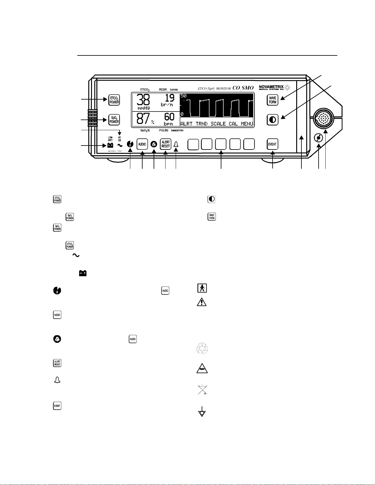
Front Panel Controls and Connectors
Front Panel Controls and Connectors
1
2
3
4
Introduction
13
12
5 6 8 9 10 15 14
1 Press to turn CO2SMO on, or if on, press to turn
off ETCO
with
2
Press to turn CO
off SpO
with
3
AC ON . If illuminated, CO
portion of monitor. Press in combination
2
to turn unit off.
SMO on, or if on, press to turn
2
portion of monitor. Press in combination
2
to turn unit off.
SMO is connected to
2
AC Mains power and charging internal battery.
LOW BAT . Illuminates when approximately 15
4
minutes of battery life remain.
5 (Two Minute Silence). Illuminates when
key is
pressed. Indicates audible alerts are silenced for two
minutes.
6 Press and release to start Two Minute Silence, or
stop Two Minute Silence or Audio Off. Press and hold
three seconds to start Audio Off.
7 (Audio Off).Flashes when key is pressed for
three seconds. Indicates audible alerts have been
disabled.
8 Press to turn off alert indicators. Alerts will
reactivate if still valid.
9 (Alert). Flashes red as soon as an alert occurs.
10 Softkeys (5). Perform the action annotated in the
Message Center above each key.
11
Press to mark an “event” in trend memory. When
pressed while in the Main Menu the waveform is
frozen for sixty seconds. Pressing the
RUN softkey
will return to real time instantly.
167 11
12 (Contrast). Press to adjust display contrast for
optimum viewing.
13
Press to switch between capnogram,
plethysmogram, or dual waveform displays
14 CO
Input Connector. Plug the CAPNOSTAT CO2
2
Sensor in here.
15 Sampling System Inlet Connector. The Sampling
Airway Adapter tubing plugs in here.
16 Red Alert Bar. Flashes red when alert is latched.
Symbols:
Patient isolation: Identifies connection as type BF
Attention: Consult manual for detailed information
Indicates heavy metal content, specifically lead.
Found on the internal battery and monitor enclosure.
Pb
Refer to qualified service personnel when battery
replacement is required.
Recyclable item. Found on the internal battery. Refer
to qualified service personnel when battery
replacement is required.
Mains fuse rating for replacement fuses.
250V
Separate collection. Ensure that spent batteries are
collected separately when disposed of. Found on the
internal battery. Refer to qualified service personnel
when battery replacement is required.
Equipotentiality: Connection to monitor’s chassis
Rev. 04
CO2SMO
User’s Manual
5
Page 18
Section 1
Front Panel Controls and Connectors
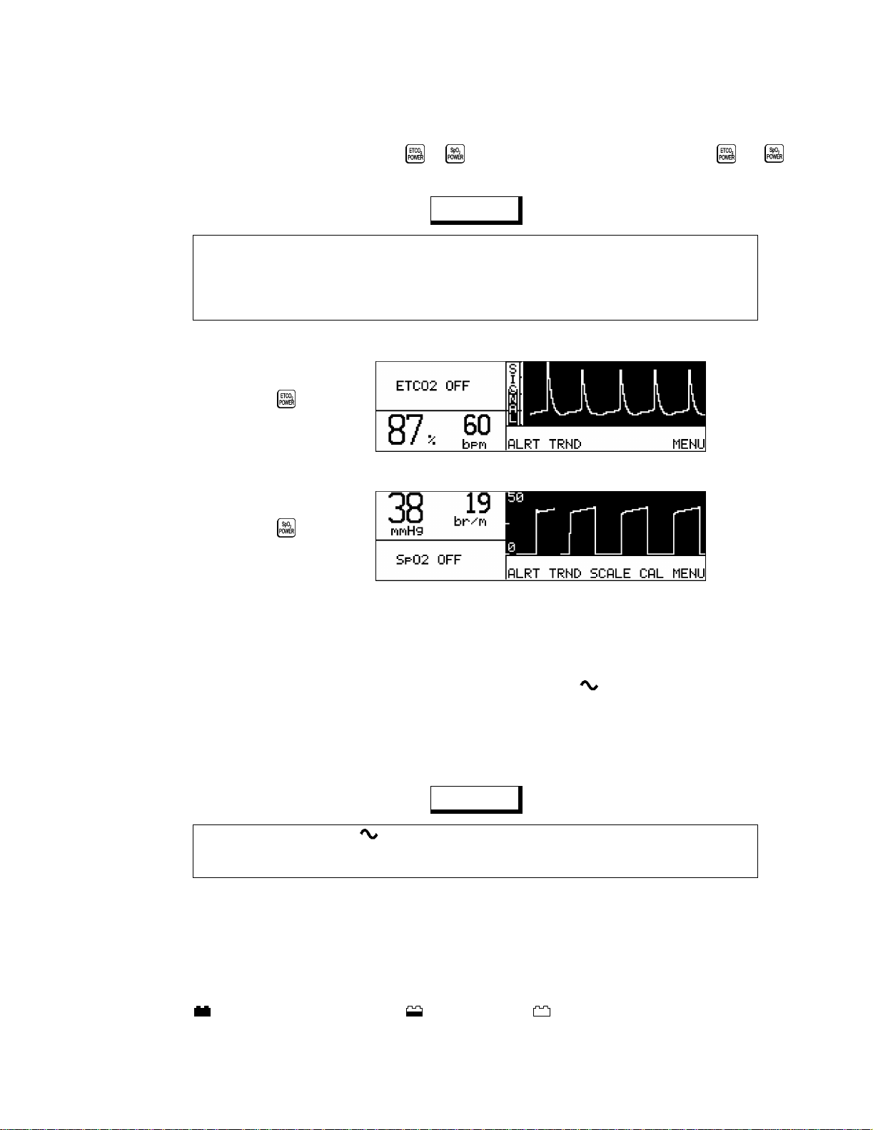
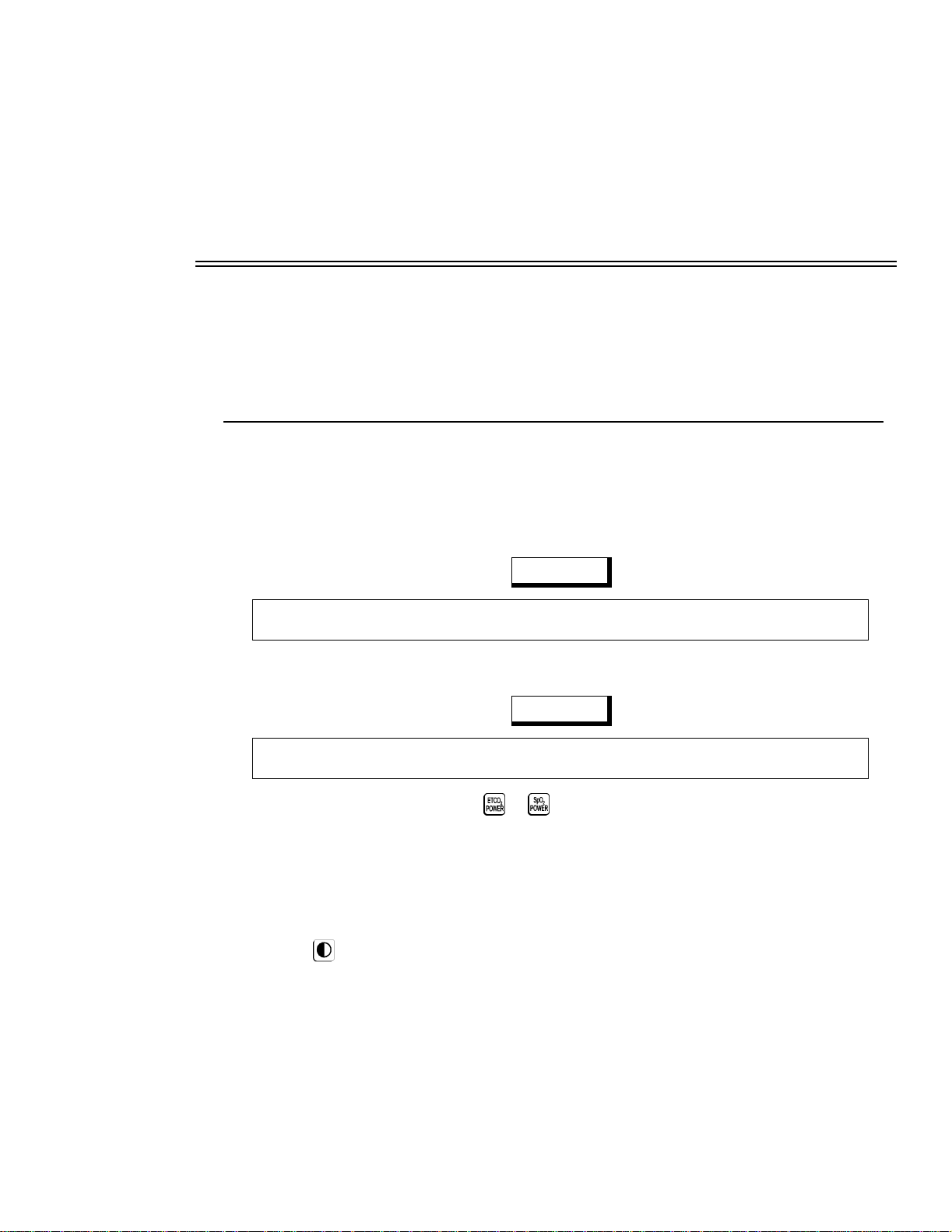
POWER Keys
To turn CO
SMO on, press either the or key. To turn the monitor off, press both the and
2
keys.
NO T E
CO2SMO powers up as a combined ETCO2/SpO2 monitor. If only the capnograph or pul se oximeter
portion is going to be used, th e unused half can be disabled to avoid nuisance alerts and error
messages. With the monitor turned on, press either POWER key to shut down that half of the monitor.
Press the key again turn that half back on. T o turn CO
the power key associated with the active parameter.
Press key
to turn off CO
Press key
to turn off SpO
2
2
SMO off while only one parameter is active, press
2
AC Mains Operation
CO2SMO uses AC Mains ( line cord ) po wer if available and automatically switches to battery operation if
AC Mains power is removed or not present. An illuminated AC ON indicator means the
CO2SMO is
connected to AC Mains power and the internal battery is being charged.
To power
CO2SMO from AC Mains (line cord) power; P lug the line cord into the rear panel AC input
connector . Set the rear panel po wer switch to the “|” (ON) position. Plug the other end of the line cord to
a properly grounded three-wire outlet.
NOTE
Caution: Ensure the AC ON indicator is illuminated w hen operation from AC mains is desired,
otherwise power for the monitor is drawn from the internal battery. This can result in the monitor shutting
itself off if the battery is allowed to drop to the low battery state. See “Battery Operation” on page 6.
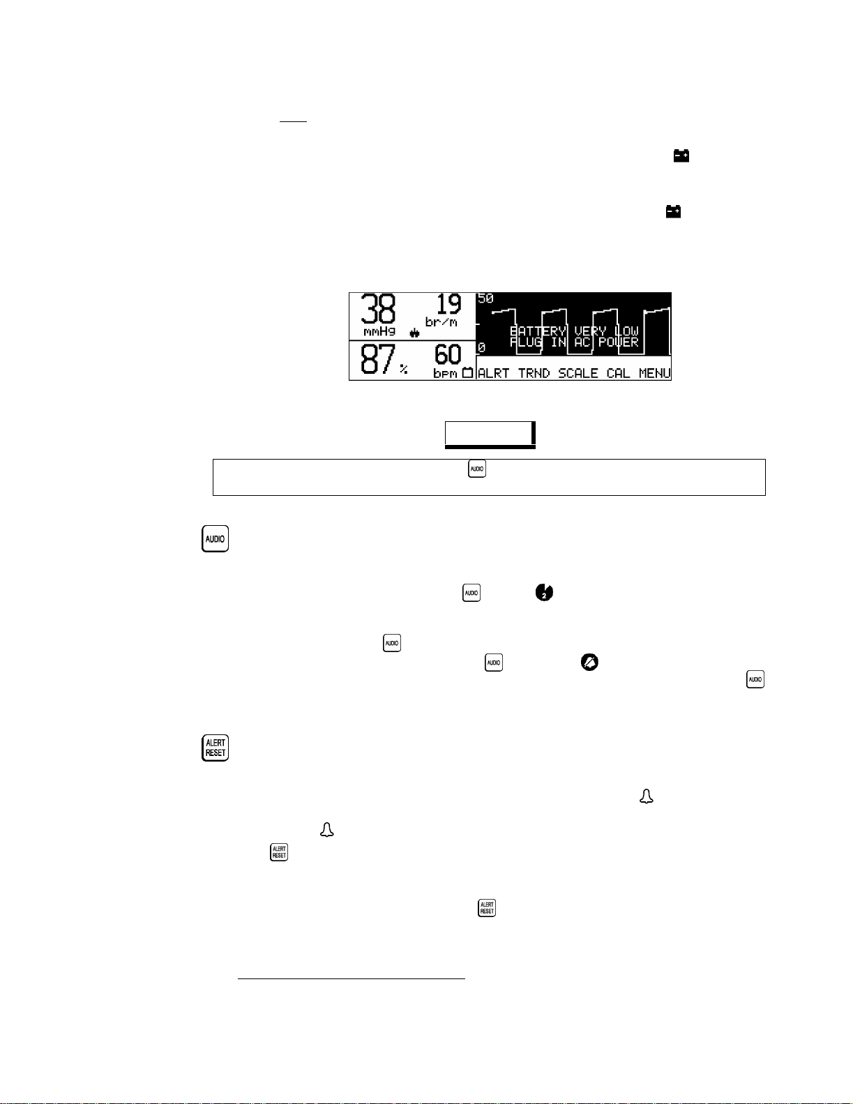
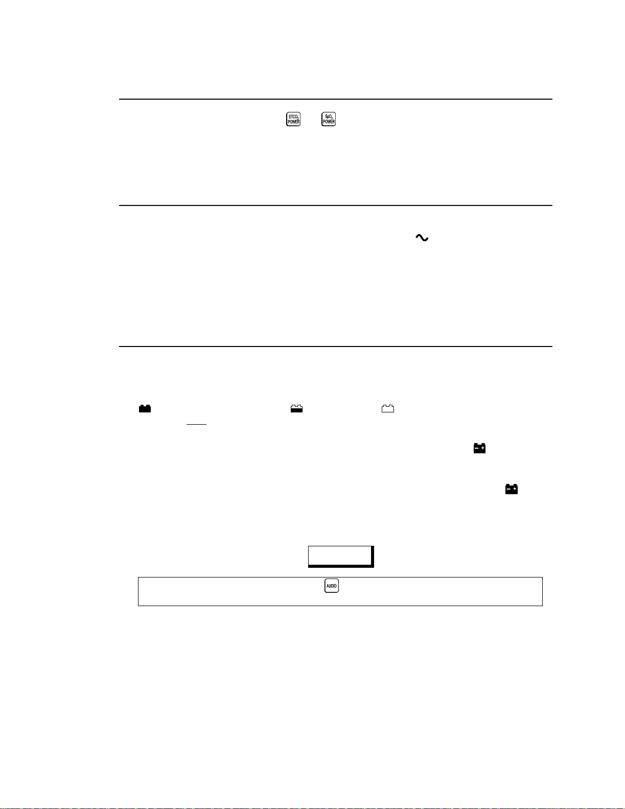
Battery Operation
CO2SMO uses battery power if the line cord is disconnected or the rear panel power switch is set to the
“O” (OFF) position.
While on battery power,
indicates a fully charged battery, a half charge, and indicates less than 30 minutes of battery
CO2SMO can operate up to two hours from its internal battery.
CO2SMO displays a battery icon to the right of the numerical Respiration display .
6
CO2SMO
User’s Manual Rev. 04
Page 19
Front Panel Controls and Connectors
life remain. Note: The battery icon may appear fully ch arged for the first minute after switching to battery
power: wait one minute for the icon to truly reflect battery charge.
When approximately 15 minutes of battery life remains, the front panel
flash. Reconnect the monitor to the AC Mains to rechar ge the battery. The monitor can be operated from
the AC Mains while the battery is being recharged. The battery will be fully recharged in 12-15 hours.
If the monitor continues operating on battery power while in the lo w battery state ( indicator flashing),
the message
continue operation while in the very low battery state, the monitor shuts itself off to prevent damage to
the battery and monitor.
BATTERY VERY LOW PLUG IN AC POWER is displayed. If the monitor is al lowed to
Introduction
LOW BAT indicator starts to
NOTE
This alert cannot be silenced by pressing the key. The monitor must be connected to AC Mains
power to silence the alert condition and recharge the battery. See “A C Mains Operation” on page 6.
AUDIO Key
Audible alarms can be silenced in two ways; temporarily or permanently.
• Two Minute Alarm Silence: Press the key. The (two minute silence) indicator illuminates
and audible alerts are silenced for two minutes. After two minutes, the indicator turns off and
audible alerts are again allowed to sound. To cancel the two minute silence before the two minutes
have elapsed, press the key again and the silence condition will be cancelled.
• Permanent Audio Off: Press and hold the key until the (audio off) indicator starts
flashing
again: it will stop flashing and audible alerts are again allowed to sound.
*
. No audible alerts will be generated. To cancel the audio off condition , press the key
ALERT RESET Key
An alert occurs if ETCO2, respiration rate, SpO2 or pulse rate exceeds the displayed alert limits. Alerts
are also generated by conditions such as NO RESP. When an alert occurs, the (alert) indicator flashes,
and the violated limit displays and the red alert bar may flash and an alarm may sound. Once the alert
condition is fixed, and other flashing displays may continue even though the audible alarms stop.
Press the key to stop an alert condition that is not currently active. Any alert messages, flashing
indicators or audible alerts will be disabled. Currently acti ve alerts will be re set and aga in become acti v e
once any time-out period has elapsed.
In certain conditions such as NO RESP, pressing will reset (silence) the audible alerts until monitoring
is resumed and the monitor again displays end tidal and respiration rate values.
Rev. 04
*If AUDIO OFF DISABLED appears when the user activates AUDIO OFF, refer to “Audio Mute” on page 63.
CO2SMO
User’s Manual
7
Page 20
Section 1
Front Panel Controls and Connectors
The Menu SOFTKEYS
The Menu Center display area is located just above the five unmarked “softkeys”. Softkeys perform the
action displayed above each key. For example; above the rightmost softkey in the Main (or Base) Menu
is a
MENU key. Press MENU and new menu and softkey functions are displayed. Press RUN to return to
the Main Menu.
NOTE
RUN always displays the Main Menu. NEXT and PREV (previous) move through the menus one level
at a time. The Main Menu will reappear if no key is pressed f or one minute. The time out is e xtended to
five minutes if trends are displayed.
The Main (or Base) Menu is comprised of the following keys
ALRT - Set alert limits, either manually or with Auto Alerts.
•
TRND - Trend page menus and displays.
•
•
SCALE - Capnogram sweep speed and vertical scale controls
•
CAL -Airway Adapter calibration menus
MENU -Access CO2 OPTIONS (O
•
OPTIONS
(audible alert volume, bright/dim display, averaging time) menus.
0 compensation, sampling pump on/off) and SYSTEM
2/N2
:
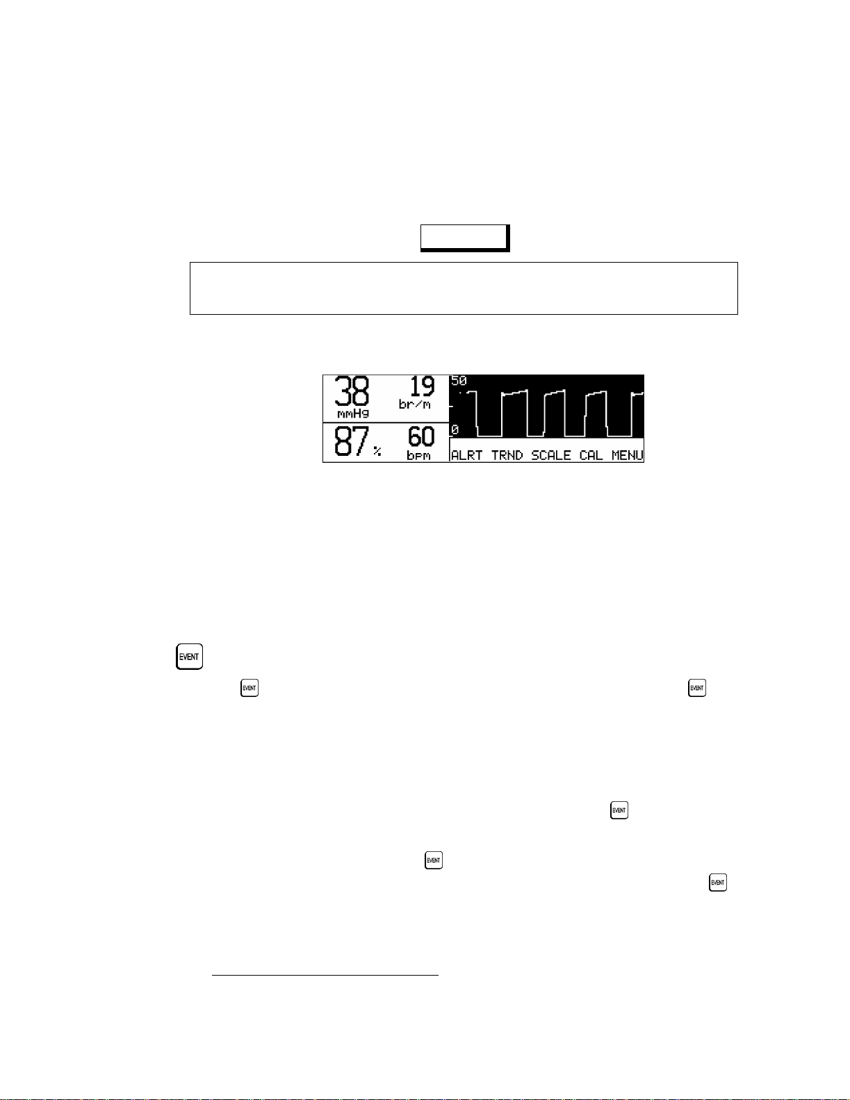
EVENT Key
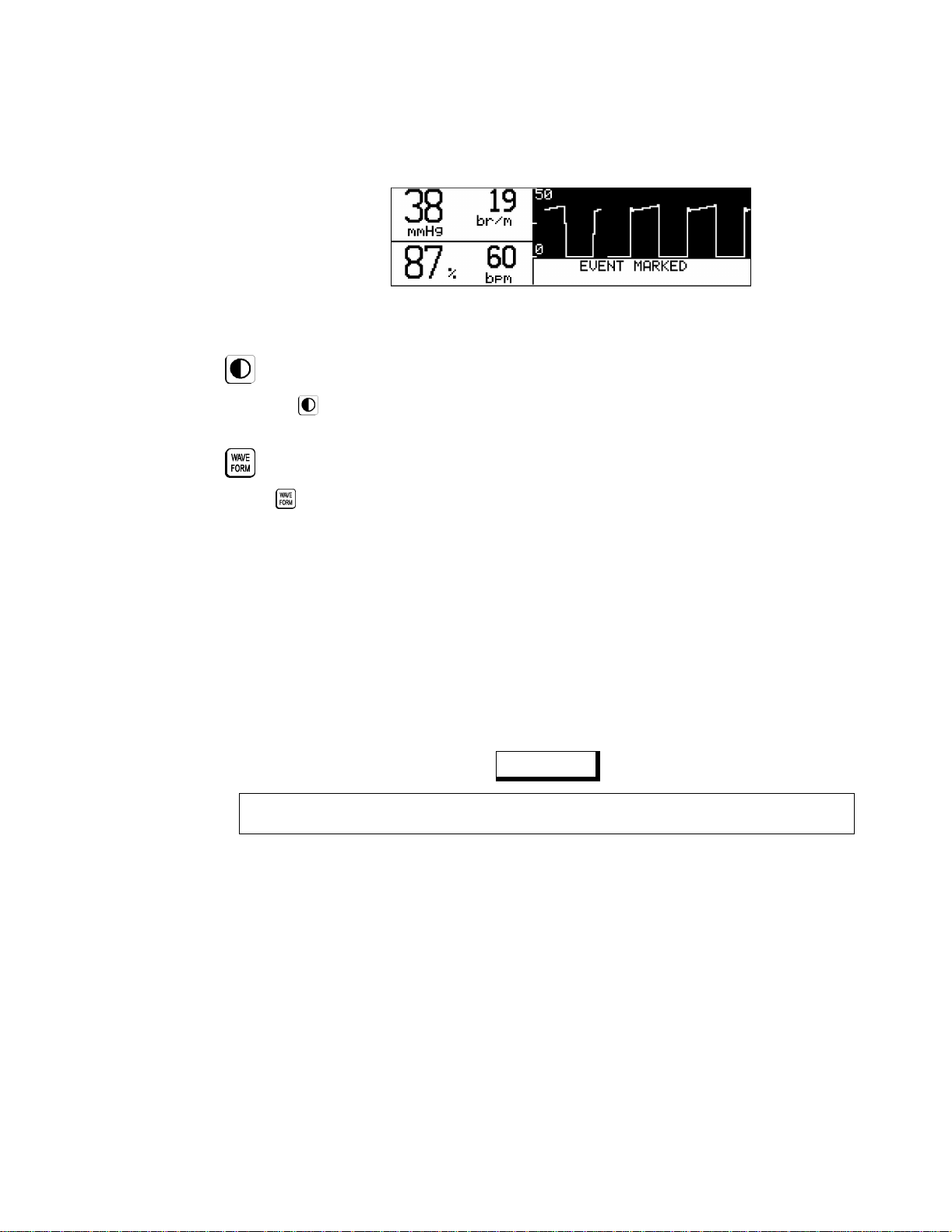
Press the key to place an “e ven t” marker into the mon itor’s trend memory. Pressing th e key while
in the Main Menu will freeze the waveform for sixty seconds, the message
appears on the display. To return to the real time display before the sixty second time out press the RUN
softkey. Pressing the EVENT softkey in menus other than the Main Menu will not freeze the waveform,
the event will however be recorded in trend memory. Events are stored in trend memory for use in
printouts and trend data examination. The message
EVENT MARKED is displayed each time an event is
marked.
When the
CO2SMO is configured for operation with a printer and the key is pressed, PRINT
WAVEFORM? will be displayed for approximately 60 seconds. Pressing the
will cause a printout of the waveform. The duration of this printout will be the 10 second interval
immediately preceding the pressing of the key.
When the
CO2SMO is config ured fo r o peration with the NOVACARD memory module and the key is
pressed, STORE WAVEFORM? will be displayed for 60 seconds. Pressing the
WAVE FO R M FROZEN
PRINT key during this time
STORE key will store the
8
CO2SMO
Based on factory default settings.
User’s Manual Rev. 04
Page 21
Front Panel Controls and Connectors
waveform to the NOVACARD. Pressing ID will bring up the patient ID menu. The ERASE softkey will
erase the card. Pressing
CONTRAST Key
Press the (contrast) key to adjust the display for optimum viewing.
WAVEFORM Key
Press key to display the capnogram, plethysmogram, or dual waveform.
Introduction
RUN will return to real time display.
Red Alert Bar
The Red Alert Bar flashes when an alert occurs. The bar can be set to; “latched”, where the bar flashes
until the presses
inside its limits; or “off”, where the bar will not turn on at all.
ALERT RESET; “unlatched”, the bar stops flashing when the alerting param eter returns
CAPNOSTAT CO2 Sensor Input Connector
The CAPNOSTAT CO2 Sensor plugs into this connector.
CAUTION
Connect only a Novametrix Catalog No. 7167, CAPNOSTAT CO2 Sensor to the CO2SMO CO2 Input
Connector. Do not use other CO
INCOMPATIBLE CO2 SENSOR message indicates a non-compatible sensor is connected.
An
sensors with the CO2SMO.
2
Sampling System Inlet Connector
The Sampling Airway Adapter tubing plugs into this connector.
Rev. 04
CO2SMO
User’s Manual
9
Page 22

Section 1
Rear Panel Controls and Connectors
Rear Panel Controls and Connectors
SpO2 Input Connector
The SpO2 Sensor plugs into this connector.
CAUTION
Connect only Novametrix SuperBright SpO2 sensors to the CO2SMO SpO2 Input Connector. Do not use
other SpO
INCOMP SpO2 PROBE message indicates a non-compatible sensor is connected.
An
AC Mains Power Module
The AC Ma ins line cor d plugs into the Po wer I nput Module a nd is held in place with the line c ord retaini ng
clip. The monitor’s voltage setting (i.e., 115 VAC) is displayed on the module. When the power switch is
set to the “|” position, AC Mains line voltage will power the monitor and recharge the battery (if the line
cord is connected). If the po wer swit ch is set to the “ O” position , A C Mains li ne vo ltage is pre v ented from
reaching the monitor’s power supply and the monitor must operate from its internal battery.
sensors with CO2SMO.
2
Sampling System Exhaust Connector
This port is provided so that gas analyzed with the Sampling Airway Adapter and tubing can be
scavenged as needed.
Data Communications Port
The “RS232C/Novametrix Accessories” con nector pr ovides an interf ace to ex ternal equipm ent such as a
printer and other external optional accessoriesw
10
CO2SMO
User’s Manual Rev. 04
Page 23

Section 2
Patient Safety
The CO
ground is limited to less than 10 µA at 120 VAC, 60 Hz. Patient isolation is greater than 10 MΩ, 2500
VAC rms at 60 Hz.
SMO SpO
2
Indications and Usage
The CO
respiration rate, functional oxy gen saturation and pulse rate in all critical monitoring environments
including ventilatory support, patient transport and anesthesia.
patients including adult, pediatric and neonatal.
The following factors can inf luence CO
pressure, water vapor and halogenated agents.
For maximum patient and operator safety, you must follow the following warnings and cautions.
SMO ETCO
2
Warnings
!
Indicates a potentially harmful condition that can lead to personal injury
Input is electrically isolated. Patient leakage current flowing from the instrument to
2
Monitor, Model 7100, is intended to be used for monitoring end tidal C O2,
2
CO2SMO is designed to monitor all
CO2SMO is not intended for any other purpose.
measurement; nitrous oxide, ele vated oxygen le vels, barometric
2
W ARNING
Rev. 04
• Explosion Hazard: Do NOT use CO
instrument in such an environment may present an explosion hazard.
• Electrical Shock Hazard: Always turn
Do NOT use a damaged sensor or one with exposed electrical contacts. Refer servicing to
qualified service personnel.
• Failure of Operation: If the monitor fails to re spond as described, do not use it until the situation
has been corrected by qualified personnel.
• Do not operate
• Do not operate
• Keep
• Never sterilize or immerse the monitor in liquids.
• Connect the line cord only to a grounded hospital-grade outlet.
• Patient Safety: Care should be exercised to assure continued peripheral perfusion distal to the
CO2SMO and its accessories clean.
the same electrical circuit as other equipment in use on the patient. Outlets on the same circuit can
be identified by the hospital’s engineering department.
SpO
sensor site after application.
2
CO2SMO when it is wet due to spills or condensation.
CO2SMO if it appears to have been dropped or damaged.
SMO in the presence of flammable anesthetics. Use of this
2
CO2SMO off, and remove the line cord b efore cleaning it.
CO2SMO should be connected to
CO2SMO
User’s Manual
11
Page 24

Section 2
Cautions
•The CO
SMO is not intended to be used as a primary diagnostic apnea monitor and/or recording
2
device.
• Inspect the SpO
sensor site often for adequate circulation - at least once every fo ur hour s. When
2
applying sensors take note of the patient’s physiological condition. For example, burn patients
may exhibit more sensitivity to heat and pressure and therefore additional consideration such as
more frequent site checks may be appropriate.
• Data Validity: As with all pulse oximeters, inaccu rate SpO
and Pulse Rate values can be caused
2
by any of the following:
• Incorrect application or use of a sensor
• Significant levels of dysfunctional hemoglobin; carboxyhemoglobin or methemoglobin
• Significant levels of indocyanine green, methylene blue, or other intravascular dyes
• Exposure to excessive illumination such as surgical lamp s—especially ones with a xenon
light source, or direct sunlight
• Excessive patient movement, venous pulsations, electrosurgical interference
• Data Validity: The Pulse Oximeter should not be used as a substitute for an ECG monitor. The
oximeter’s Pulse Rate display reflects the pulsatile flow found at the p atien t extr emity co nnected
to the sensor. This rate can be affected by many factors and may occasionally be “frozen.”
• Do NOT attach an SpO
sensor distal to a blood pressure cuff. Valid data CANNOT be processed
2
when the cuff is inflated. Attach the sensor to the limb opposite to the site used for the blood
pressure cuff.
• A “NO RESPIRATION” alert is not generated when the CAPNOSTAT CO
Sensor is not
2
connected to the monitor.
•
The CO2SMO has no protection against the ingress of water.
Cautions
CAUTION
Indicates a condition that may lead to equipment damage or malfunction.!
• Do not operate CO
• Do not operate
• Never sterilize or immerse the monitor in liquids.
• Do not sterilize or immerse sensors except as directed in this manual.
• Tension should not be applied to the sensor cable.
• Overstretching the pulse oximeter finger sensor can damage the sensor and potentially aff ect pulse
oximeter readings. Do not stretch the finger sensor open beyond the limit for which it was
designed. Overstretching can be prevented: avoid opening the sensor by any means other than
squeezing the grips; Do NOT force the sensor onto large objects such as the bed rail.
• In case of interference with our equipment or another manufacturer’s equipment, notify your
Novametrix representative.
• Do NOT attach an SpO
when the cuff is inflated. Attach the sensor to the limb opposite to the site used for the blood
pressure cuff.
• Care should be exercised to assure continued peripheral perfusion distal to the SpO
after application
SMO when it is wet due to spills or condensation.
2
CO2SMO if it appears to have been dropped or damaged.
sensor distal to a blood pressure cuff. Valid data CANNOT be processed
2
sensor site
2
12
CO2SMO
User’s Manual Rev. 04
Page 25

Cautions
Patient Safety
• Do not store the monitor or sensors at temperatures less than 14° F (-10° C) or greater than 131°
F (55° C).
• Do not operate the monitor or sensors at temp eratures less than 50 ° F ( 10° C) or greater than 104°
F (40° C).
• Caution: Federal (U.S.A.) law restricts this device to sale, distribution, or use by or on the order
of a licensed medical practitioner.
NOTES
Indicates points of particular interest or emphasis for more efficient or convenient operation.
• Components of this product and its associated accessories which have patient contact are free of
latex.
• After the life cycle of our equipment and all accessories has been met, disposal of the equipment
should be accomplished following the national requirements. Contact the local Novametrix
representative for questions concerning disposal.
Rev. 04
CO2SMO
User’s Manual
13
Page 26

Section 2
Cautions
[This page intentionally blank.]
14
CO2SMO
User’s Manual Rev. 04
Page 27
Section 3
Monitor Power Up
This section explains how to turn the CO
operation.
SMO on and off. It also explains AC Mains and battery power
2
Monitor Power Up
1. Verify CAPNOSTAT CO2 and SpO2 Sensor integrity.
Ensure sensors and their extension cables ar e physically intact with no broken, frayed or
damaged components.
2. Plug the CAPNOSTAT CO
Connect only a Novametrix Catalog No. 7067 or 7167, CAPNOSTA T CO2 Sensors to CO2SMO. Do
not use other CO
3. Plug an SpO
Connect only Novametrix SuperBright SpO2 sensors to the CO2SMO. Do not use other SpO
sensors with CO2SMO.
sensors with the CO2SMO.
2
sensor (or extension cable) into the rear panel input connector.
2
Sensor into the front panel input connector.
2
CAUTION
CAUTION
2
Rev. 04
4. To turn
5. Press the (contrast) key to adjust the display for optimum viewing.
6. Press
CO2SMO on, press either the or key.
Ensure all displays and indicators illuminate briefly . En sure a “beep” sounds to indicate that the
audio is working. Verify a “Self Test in progress” appears followed by the main menu.
CO2SMO powers up as a combined ETCO
oximeter portion is going to be used, the unused half can be disabled to avoid nuisance alerts
and error messages. With the monitor turned on, press either power key to shut down that half
of the monitor. Press the key again turn that half back on.
YES to erase or press NO to retain stored trend information.
“ERASE STORED TRENDS?” is briefly displayed after p ower on. Press YES to erase the tren d
data stored during previous monitoring episodes. To keep the stored trend data intact, press the
NO key (or don’t press any key and let the menu time out).
/SpO2 monitor. If only the capnograph or pulse
2
CO2SMO
User’s Manual
15
Page 28
Section 3
Monitor Power Down
Monitor Power Down
1. To turn CO
SMO off, press both the and keys.
2
T o turn
active parameter.
CO2SMO off while only one parameter is acti ve, press the po wer ke y associated with the
AC Mains Operation
CO2SMO uses AC Mains ( line cord ) po wer if available and automatically switches to battery operation if
AC Mains power is removed or not present. An illuminated
connected to AC Mains power and the internal battery is being charged.
To power
connector . Set the rear panel power switch to the “|” (ON) p osition. Plug the other end o f th e lin e co rd to
a properly grounded three-wire outlet.
CO2SMO from AC Mains (line cord) power; P lug the line cord into the rear panel AC input
AC ON indicator means the CO2SMO is
Battery Operati on
CO2SMO uses battery power if the line cord is disconnected or the rear panel power switch is set to the
“O” (OFF) position.
While on battery power,
indicates a fully charged battery, a half charge, and indicates less than 30 minutes of battery
life remain. Note
power: wait one minute for the icon to truly reflect battery charge.
When approximately 15 minutes of battery life remain, the front panel
flash. Reconnect the monitor to the AC Mains to rechar ge the battery. The monitor can be operated from
the AC Mains while the battery is being recharged. The battery will be fully recharged in 12-15 hours.
If the monitor continues operating on battery power while in the low battery state ( indicator
flashing), the message
to continue operation while in the very low battery state, the monitor will alert, then shut itself off to
prevent damage to the battery and monitor.
CO2SMO can operate up to two hours from its internal battery.
CO2SMO displays a battery icon to the right of the numerical Respiration display .
: The battery icon may appear fully charg ed for the first minute after switching to battery
LOW BAT indicator starts to
BA TTER Y VER Y LOW PL UG IN AC POW ER is displayed. If the mon itor is allowed
16
CO2SMO
NOTE
This alert cannot be silenc ed b y pressi ng the key. The monitor must be connec ted to A C Mai ns
power to si lence the alert condit ion an d recharge the ba ttery. See “AC Mains Oper ation” o n page6.
User’s Manual Rev. 04
Page 29

Section 4
This section explains how to select an airway adapter based on the patient to be monitored, connect the
airway adapter to the CAPNOSTAT CO
to calibrate the airway adapter and sensor.
Airway Adapter Selection
Select an airway adapter based on the patient and monitoring situation.
• Adult Airway Adapter (Catalog No. 7007)
For patients with Endotracheal Tube diameters greater than 4.0 mm.
• Single Patient Use Adult Airway Adapter (Catalog No. 6063)
For single patient use with Endotracheal Tube diameters greater than 4.0 mm.
• Single Patient Use Adult Airway Adapter with Mouthpiece (Catalog No. 6421)
For single patient use for spot checking CO
• Neonatal Airway Adapter (Catalog No. 7053)
For patients with Endotracheal Tube diameters less than or equal to 4.0 mm.
• Single Patient Use Neonatal Airway Adapter (Cat. No. 6312)
For monitoring intubated patients with an ET tube size of 4.0 or smaller.
• Sampling Airway Adapter with tubing (Catalog No. 5843)
For non-intubated patients when used in conjunction with a nasal sampling cannula.
CAPNOSTAT CO2 Sensor
Sensor and to the patient’s airway circuit, and how and when
2
on non-intubated adult or pediatric patients.
2
Rev. 04
Adult Airway Adapter
The Adult Airway Adapter (Catalog No. 7007) should be used when monitoring patients with
Endotracheal Tube diameters greater than 4.0 mm. Alternatively, the Single Patient Use Adult Airway
Adapter (Catalog No. 6063) may be used. See “Single Patient Use Adult Airway Adapter” on page 19.
1. Verify the windows are clean and dry. Clean or replace the adapter if necessary.
2. Snap the airway adapter into the CAPNOSTAT CO
Align the arrow on the bottom of the airway adapter with the arrow on the bottom of the
CAPNOSTAT C O
3. If necessary, perform an adapter calibration. Otherwise, skip this step.
Adapter Calibration needs to be performed each time you switch airway adapter types—for
example; if you switch from using an Adult to a Neonatal adapter , b ut not if you switch from an
Adult adapter to another Adult adapter. Adapter Calibration should also be performed if the
monitor displays
To perform an Adapter Calibration:
Sensor. Press the sensor and airway adapter together until they “click”.
2
ADAPTER CAL?.
Sensor.
2
CO2SMO
User’s Manual
17
Page 30
Section 4
Adult Airway Adapter
Press CAL. PLACE ON ADPT IN RM AIR message appears.
Place the sensor and airway adapter away from all sources of CO
(including the patient’ s—
2
and your own—exhaled breath, and ventilator exhaust valves).
Press
START. TIME REMAINING counts down and the Main Menu reappears.
The actual calibration will take typically less than 15 seconds.
NOTE
If the monitor detects changing CO2 levels (breaths) during an adapter calibration, BREATHS
DETECTED? is display ed follow ed by PLA CE ON ADPT IN RM AIR. To continue, remov e the source
, wait 30 seconds, and press START.
of CO
2
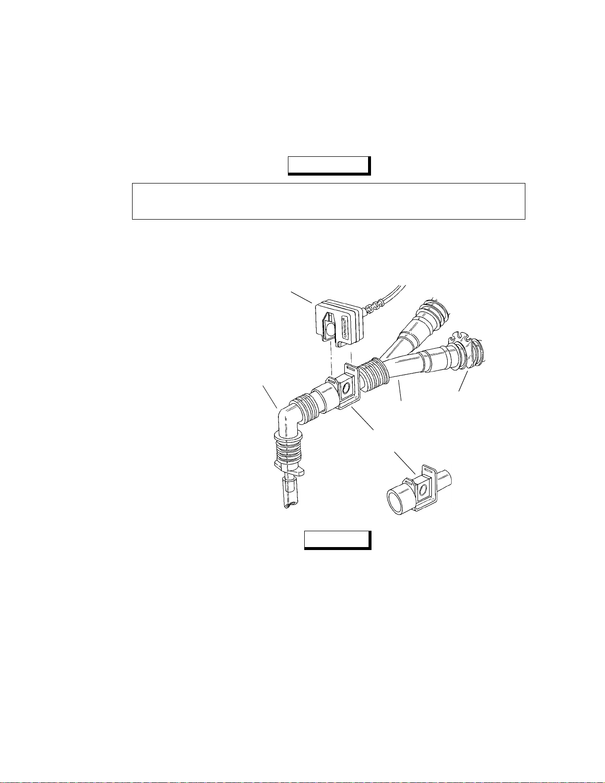
4. When using the Adult Airway Adapter, place the CAPNOSTAT CO
Sensor/Airway Adapter assembly
2
at the proximal end of the airway circuit between the elbow and the ventilator circuit wye.
Shown with CAPNOSTAT
Sensor Cat. No. 7167
CO
2
(may also use Cat. No. 7067)
Elbow
Wye
Adult Airway Adapter
(Cat. No. 7007)
To
Patient
(Cat. No. 8751)
To
Ventilator
Cable Clip
18
CO2SMO
NOTE
• For optimal results, do NOT place the airway adapter between the ET tube and the elbow, as this
may allow patient secretions to block the adapter windows.
• Position the Airway Adapter with its windows in a vertical and NOT a horizontal position: This
helps keep patient secretions from “pooling” on the windows. If pooling does occur, the airway
adapter may be removed from the circuit, rinsed with water and reinserted into the circuit.
• To prevent “rain-out” and moisture from draining into the Airway Adapter, do NOT place the
Airway Adapter in a gravity dependent position.
5. Check that the connections ha ve been made correctly by verifying a proper CO
on the monitor display.
6. The sensor cable should face away from the patient.
User’s Manual Rev. 04
wavefo rm (capnogram)
2
Page 31

Single Patient Use Adult Airway Adapter
T o secure the sensor cable safely out of th e way , attach Sensor Cable Holdin g Clips to the airway
tubing, then connect the sensor cable to the clips (Cat. No. 8751).
CAPNOSTAT CO2 Sensor
7. See “Monitoring CO
and Respiratory Rate” on page 29.
2
Single Patient Use Adult Airway Adapter
The Single Patient Use Adult Airway Adapter (Catalog No. 6063) should be used when monitoring
patients with Endotracheal Tube diameters greater than 4.0 mm. Alternatively, the (reusable) Adult
Airway Adapter (Catalog No 7007) may be used. See “Adult Airway Adapter” on page 17.
WARNING
The Single Patient Use Adult Airway Adapter is intended for single patient use, do not re-use or
sterilize the adapter as system performance may be compromised.
1. Remove the adapter from the package. Verify the adapter is intact.
2. Snap the Single Patient Use airway adapter into the CAPNOSTAT CO
when properly seated.
3. Perform an adapter calibration.
Adapter Calibration needs to be performed each time you switch airway adapter types—for
example; if you switch from using a Neonatal to a Single Patient Use Adult adapter, but not if
you switch from one Single Patient Use Adult adapter to another Single Patient Use Adult
adapter . Adapter Calibration should also be per formed if th e monitor displays
To perform an Adapter Calibration:
Press
CAL. PLACE ON ADPT IN RM AIR message appears.
Place the sensor and airway adapter away from all sources of CO
and your own—exhaled breath, and ventilator exhaust valves).
Press
START. TIME REMAINING counts down and the Main Menu reappears.
The actual calibration will take typically less than 15 seconds.
Sensor. It will click into place
2
ADAPTER CAL?.
(including the patient’ s—
2
Rev. 04
NOTE
If the monitor detects changing CO2 levels (breaths) during an adapter calibration, BREATHS
DETECTED? is displa yed f ollowed b y PLACE ON ADPT IN RM AIR . To continue, remov e the source
, wait 30 seconds, and press START.
of CO
2
CO2SMO
User’s Manual
19
Page 32

Section 4
Single Patient Use Airway Adapter with Mouthpiece
4. Install the CAPNOST AT CO2 Sensor/Airway Adapter assembly at the p roximal end of the air way circuit
between the elbow and the ventilator circuit wye.
Shown with CAPNOSTAT
Sensor Cat. No. 7167
CO
2
(may also use Cat. No. 7067)
Elbow
To
Patient
Wye
Adult Airway Adapter
(Cat. No. 7007)
Cable Clip
(Cat. No. 8751)
To
Ventilator
NOTE
• For optimal results, do NOT place the airway adapter between the ET tube and the elbow, as this
may allow patient secretions to block the adapter windows.
• Position the Airway Adapter with its windows in a vertical and NOT a horizontal position: This
helps keep patient secretions from “pooling” on the windows. If pooling does occur, the airway
adapter may be removed from the circuit, rinsed with water and reinserted into the circuit.
• To prevent “rain-out” and moisture from draining into the Airway Adapter, do NOT place the
Airway Adapter in a gravity dependent position.
20
CO2SMO
Single Patient Use Airway Adapter with Mouthpiece
The single patient use airway adapter with mouthpiece (Catalog No. 6421 ) can be used for spot check ing
CO
on non-intubated adult or pediatric patients.
2
CAUTION
The airway a dapter wi th mout hpiec e is intend ed f or sin gle pati en t use . Do not re -use or s teriliz e the
adapter, as system performance will be compromised.
Instructions for use:
1. Verify that the adapter and mouthpiece are intact and securely fastened to each other.
User’s Manual Rev. 04
Page 33

Neonatal Airway Adapter
2. Press the CA PNOSTAT® CO2 Sensor onto the airway adapter. It will click into place when properly
seated. The CAPNOSTAT CO
3. Perform an airway zero only if prompted by the monitor.
An airway zero is not needed if a single patient use adapter had previously been used. An airway zero
should be performed only if the monitor displays “
To perform an airway zero:
4. Patient should seal mouth completely around the mouthpiece, then breathe normally.
CAPNOSTAT CO2 Sensor
Sensor cable should be facing away from the mouthpiece.
2
Direction of sensor cable
CAPNOSTAT CO2 Sensor
Mouthpiece
Airway adapter
To patient
ADAPTER CAL?”.
3a. Press
3b. Place the sensor and airway adapter away from all sources of CO
3c. Press
If the monitor detects changing CO
DETECTED?
source of the CO
CAL. “PLACE ON ADPT IN RM AIR” message appears.
- and your own - exhaled breath, and ventilator exhaust valves).
START. “TIME REMAINING” counts down and the Main Menu reappears. The
actual airway zero will typically take less than 15 seconds.
levels (breaths) during an airway zero, “BREATHS
2
” is displayed followed by “PLACE ADPT IN RM AIR”. To continue, remove the
, wait 30 seconds, and press START.
2
(including the patient’ s
2
Rev. 04
Neonatal Airway Adapter
The Neonatal Airway Adapte r (Catalog No. 7053) should be use d when monitoring patients with
Endotracheal Tube diameters less than or equal to 4.0 mm.
1. Verify the windows are clean and dry. Clean or replace the adapter if necessary.
2. Snap the airway adapter into the CAPNOSTAT CO
Align the arrow on the bottom of the airway adapter with the arrow on the bottom of the
CAPNOSTAT C O
Sensor. Press the sensor and airway adapter together until they “click”.
2
3. If necessary, perform an adapter calibration. Otherwise, skip this step.
Adapter Calibration needs to be performed each time you switch airway adapter types—for
example; if you switch from using an Adult to a Neonatal adapter, but not if you switch from
Sensor.
2
CO2SMO
User’s Manual
21
Page 34

Section 4
Neonatal Airway Adapter
one Neonatal adapter to another Neonatal adapter. Adapter Calibration should also be
performed if the monitor displays
ADAPTER CAL?.
To perform an Adapter Calibration:
Press
CAL, PLACE ON ADPT IN RM AIR message appears.
Place the sensor and airway adapter away from all sources of CO
(including the patient’ s—
2
and your own—exhaled breath, and ventilator exhaust valves).
Press
START. TIME REMAINING counts down and the Main Menu reappears.
The actual calibration will take typically less than 15 seconds.
NOTE
If the monitor detects changing CO2 levels (breaths) during an adapter calibration, BREATHS
DETECTED? is display ed follow ed by PLA CE ON ADPT IN RM AIR. To continue, remov e the source
, wait 30 seconds, and press START.
of CO
2
4. When using the Neonatal Airway Adapter, place the CAPNOSTAT CO
assembly between the endotracheal tube and the ventilator circuit wye.
Shown with CAPNOSTAT
CO2 Sensor Cat. No. 7167
(may also use Cat. No. 7067)
To
Ventilator
Wye
Neonatal Airway Adapter
(Cat. No. 7053)
Sensor/Airway Adapter
2
To
Patient
22
CO2SMO
NOTE
• For optimal results, do NOT place the airway adapter between the ET tube and the elbow, as this
may allow patient secretions to block the adapter windows.
• Position the Airway Adapter with its windows in a vertical and NOT a horizontal position: This
helps keep patient secretions from “pooling” on the windows. If pooling does occur, the airway
adapter may be removed from the circuit, rinsed with water and reinserted into the circuit.
• To prevent “rain-out” and moisture from draining into the Airway Adapter, do NOT place the
Airway Adapter in a gravity dependent position.
5. Check the connections have been made correctly by verifying a proper CO
the monitor display .
User’s Manual Rev. 04
waveform (capnogram) on
2
Page 35

Single Patient Use Neonatal Airway Adapter
6. The sensor cable should face away from the patient.
CAPNOSTAT CO2 Sensor
7. See “Monitoring CO
and Respiratory Rate” on page 29.
2
Single Patient Use Neonatal Airway Adapter
The single patient use Neonatal Airway Adapter (Catalog No. 6312) should be used when monitoring
intubated patients with an ET tube size of 4.0 or smaller with Novametrix CAPNOSTAT
CO
sensors (Catalog No. 7167).
2
Deadspace: The added deadspace due to the presence of the adapter is less than .5 cc.
CAUTION
The neonatal airw ay adapter is int ended fo r single patient use . Do not re-use or steriliz e the adapter ,
as system performance will be comp romised.
®
mainstream
Instructions for Use:
1. Verify that the airway adapter is intact.
2. Align the arrow on the airway adapter with the arrow on the CAPNOSTAT CO
Sensor and press
2
together. It will “click” into place when properly seated.
3. Perform an airway zero only if promp ted by the monitor. An airway zero is not needed if a single patient
use neonatal adapter had prev io usly been used. An airway zero should be performed only if the monitor
displays “
ADAPTER CAL?” other wise, skip this step.
To perform an airway zero:
Rev. 04
CO2SMO
User’s Manual
23
Page 36

Section 4
Single Patient Use Neonatal Airway Adapter
3a. Press CAL. “PLACE ON ADPT IN RM AIR” message appears.
3b. Place the sensor with airway adapter away from all sources of CO
(including the
2
patient’ s - and your o wn - exhaled breath and ven tilator exhaust valves.)
3c. Press
START. “TIME REMAINING” counts down and the Main Menu reappears. The
actual airway zero will typically take less than 15 seconds.
If the monitor detects changing CO
DETECTED?
source of the CO
” is displayed followed by “PLACE ADPT IN RM AIR”. To continue, remove the
, wait 30 seconds and press START .
2
levels (breaths) during an airway zero, “BREATHS
2
4. Install at the proximal end of the circuit between the ET tube and the ventilator wye. The cable of the
CAPNOSTAT C O
Sensor should be facing away from the patient.
2
CAPNOSTAT CO
Ventilator wye
Neonatal airway adapter
Sensor
2
ET Tube
NOTE
• Position the airway adapter with its windows in a vertical and NOT a horizontal position: This
helps keep patient secretions from collecting on the windows. If pooling does occur, the airway
adapter may be removed from the circuit, rinsed with water and reinserted into the circuit.
• For routine performance of airway care, separate the system between the ET tube and the airway
adapter. Lavage and suctioning of the airway can then be performed without fluids and mucous
accumulating on the neonatal airway adapter windows.
5. Ensure the integrity of the patient breathing circuit after insertion of the airway adapter by verifying a
proper CO
waveform (capnogram) on the monitor display.
2
24
CO2SMO
User’s Manual Rev. 04
Page 37

Sampling Airway Adapter
Sampling Airway Adapter
The Sampling Airway Adapter with tu bing (Catalog No. 5843) shou ld be used in conjunction with a nasal
sampling cannula to monitor non-intubated patients, and to provide sidestream monitoring of pediatric
tracheostomy patients.
Non-Intubated Patients
1. Verify the windows are clean and dry. Clean or replace the adapter if necessary.
CAPNOSTAT CO2 Sensor
2. Snap the airway adapter into the CAPNOSTAT CO
Sensor.
2
Align the arrow on the bottom of the airway adapter with the arrow on the bottom of the
CAPNOSTAT CO
Sensor. Press the sensor and airway adapter together until they “click”.
2
3. Connect the sampling tubing to the Sampling Inlet port located on the front of the monitor.
4. Connect a Dehumidification Tubing Set to the Sampling Airway Adapter.
Use of the Nafion® Dehumidification Tubing Set (Cat. No. 8908) is optional. Its use is
recommended—especially during high humidity or lengthy monitoring episodes.
5. Connect a Nasal CO
Sampling Cannula to the Dehumidification Tubing Set.
2
(Or to the Sampling Airway Adapter if not using the dehumidification tubing).
Shown with CAPNOSTAT
CO2 Sensor Cat. No. 7167
(may also use Cat. No. 7067)
Nasal CO2 Cannula
(Cat. No. 8781, 8780
8906, or 8907)
Sampling Airway Adapter
with tubing (Cat. No. 5843)
Rev. 04
Dehumidification Tubing
(Cat. No. 8908)
Cat. No.
8781 Nasal CO
8780 Nasal CO
8906 Nasal CO
8907 Nasal CO
Cannula Type
Sampling Cannula—Adult
2
Sampling Cannula—Pediatric
2
Sampling and O2 Delivery Cannula—Adult
2
Sampling and O2 Delivery Cannula—Pediatric
2
6. Ensure the sampling pump is turned on—the pump icon ( ) is displayed.
To turn the sampling pump on (or off):
Press the
MENU softkey and CO2 OPTIONS appears.
CO2SMO
To Monitor
Sampling Inlet
User’s Manual
25
Page 38

Section 4
Press PUMP and SET SAMPLING PUMP appears.
ON to turn the sampling pump on (or press OFF to turn the pump off).
Press
7. If necessary, perform an adapter calibration. Otherwise, skip this step.
Adapter Calibration is necessary when the pump is first turned on; in order to set the sampling
system alert thresholds, and to compensate for the unique optical character istics of the sampling
airway adapter. After the first sampling adapter calibration, subsequent patient setups using
sampling adapters do not require adap ter calibration —so long as the pump i s not turned o f f an d
similar cannula/dryer tubing combinations are used. Adapter Calibration should also be
performed if the monitor displays
CAL CO2 CANNULA.
To perform a Sampling Adapter Calibration:
• Press
CAL and CO2 CANNULA ATTACHED ? appears.
• Verify the cannula (and dryer tubing, if used) is attached to the adapter, and the adapter tubing is
attached to the monitor.
• Press
• Place the cannula away from all sources of C O
CONT (continue) and PLACE ON ADPT IN RM AIR appears.
(including the patient’s—and your own—exhaled
2
breath, and ventilator exhaust valves).
• Press
START. TIME REMAINING counts down and the Main Menu reappears.
The actual calibration will take typically less than 15 seconds.
Sampling Airway Adapter
NOTE
If the monitor detects changing CO2 levels (breaths) during an adapter calibration, BREATHS
DETECTED? i s displayed followed by PLACE ON ADPT I N RM AIR. To continue, remove the
source of CO2, wait 30 seconds, and press START.
8. If using a Nasal CO
device and set the device to the prescribed O
Sampling and O2 Delivery Cannula, attach the O2 tubing to the administration
2
setting.
2
9. Position the cannula on the patient.
Insert the cannula tips into the nostrils, pass the cannula tubing over the ears, then slide the retaining
sleeve up the tubing toward the neck to a comfortable fit under chin.
10. Check the connections have been made properly by verifying a proper CO
waveform (capnogram) on
2
the monitor display .
11. Using the CAPNOSTAT CO
Sensor holding clip, secure the sensor in a convenient place (such as the
2
on the patient’s clothing or bedding).
NOTE
If possible, position the Sampling Adapter with its w indows in a vertical, and NOT a horizontal
position; this help s keep moisture from “po oli ng” on the windows. If p ool in g d oe s oc cur, the airway
adapter may be removed from the circuit, rinsed with water and reinserted into the unit.
To pr event “rain-out” and moisture from draining into the Sampling Adapt er, do NOT place the
Sampling Adapter in a gra vi ty dependent position.
26
CO2SMO
12. Use the twist clips to connect the sensor cable and sampling tubing together, then place them out of the
way.
13. See “Monitoring CO
User’s Manual Rev. 04
and Respiratory Rate” on page 29.
2
Page 39

Calibration
CAPNOSTAT CO2 Sensor
Calibration
Sensor Calibration
The CAPNOSTAT CO2 Sensor does NOT require calibration at each monitor power up.
Calibration of a particular CAPNOSTAT CO
calibration, and (2), the first time a particular sensor is connected to a particular monitor—as is the case
the first time you power up your
Once calibrated,
CO2SMO can be turned off and o n, and the CAPNOSTAT CO
CO2SMO and CAPNOSTAT CO
and reconnected, without having to recalibrate. However, if a second CAPNOSTAT CO
connected in place of the original, the new sensor must be calibrated—and if at a later time the original
sensor is reconnected, it too will then have to be recalibrated.
To perform a CAPNOSTAT CO
1. Verify the
CO2SMO is turned on and the CAPNOSTAT CO
2. Place the CAPNOSTAT CO
Sensor calibration;
2
sensor onto the ZERO cell. A TIME REMAINING counter is displayed.
2
The sensor cable should face away from the
sensor is not at operating temperature (as migh t be the case if the monitor was just tur ned on or
the sensor was just plugged in). The
being calibrated and will usually appear within ab out one to tw o minutes. The actual calibration
will take typically less than 15 seconds.
Sensor is necessary only when (1), the monitor requests
2
Sensor.
2
Sensor can be unplugged
2
Sensor is plugged in.
2
CO2SMO. If WAIT FOR SENSOR appears, the
TIME REMAINING mes sage indicates that the se nsor is
Sensor is
2
3. After the timer counts down,
PLACE ON REF CELL appears.
4. Remove the sensor from the ZERO cell and place it on the REF (reference) cell.
The sensor cable should face away from the
5.
CHECKING CALIBRATION is displayed.
6. Within several seconds
CALIBRATION VERIFIED should appear. Remove the sensor from the cell. The
CO2SMO.
sensor is ready for use.
If
NOT CALIBRATED appears, return the sensor to the ZERO cell an d calib ration is restar ted. If
NOT CALIBRATED appears again, or if CALIBRATION ERROR appears, remov e the sensor from
use and contact the Novametrix Service Department.
Calibration Verification
The user can, at any time, quickly and easily verify CO
so periodically. Calibration verification is also warranted (and easily achieved) if clinical assessment of
patient status by alternate means leads to questions of monitor accuracy.
To verify calibration;
1. Verify the
CO2SMO is turned on and the CAPNOSTAT CO
2. Place the sensor onto the REF (reference) cell.
The reference cell is the one farthest from the face of th e monitor. The sensor cable should face
away from the
CO2SMO.
SMO/CAPNOSTAT calibration—and should do
2
Sensor is plugged in.
2
Rev. 04
3.
CHECKING CALIBRATION is displayed.
If
WAIT FOR SENSOR appear s, the sensor is no t at operating temper ature (as migh t be the case
if the monitor was just turned on or the sensor just plugged in) .
usually appear within about one minute.
CHECKING CALIBRATION will
CO2SMO
User’s Manual
27
Page 40

Section 4
Calibration
4. Within several seconds CALIBRATION VERIFIED should appear. Remove the sensor from the cell. The
sensor is ready for use.
If
NOT CALIBRATED appears, remove the sensor from the Reference cell and place it on the
Zero cell. Calibration is automatica lly started and, within 15 seconds later,
CELL
should appear. Place the sensor onto the reference cell and within several seconds
CALIBRATION VERIFIED should appear.
PLACE ON REF
Adapter Calibration
Adapter Calibration compensates for the optical differences between the Adult, Neonatal and Sampling
Airway Adapters.
Adapter Calibration needs to be performed each time you switch airway adapter types—for example; if
you switch from using an Adult to a Neonatal adapter, but not if you switch from an Adult adapter to
another Adult adapter. Adapter Calibration should also be performed if the monitor displays
CAL? or CAL CO2 CANNULA.
Refer to “Adult Airway Adapter” on page 17, “Neonatal Airway Adapter” on page 21, and “Sampling
Airway Adapter” on page 25 for specific Adapter Calibration details.
ADAPTER
28
CO2SMO
User’s Manual Rev. 04
Page 41

Section 5
Once the Capnostat CO2 Sensor and air way adapter are c onnected to the p atient’s airway circuit,
CO2SMO displays ETCO
Carbon Dioxide
Monitoring CO2 and Respiratory Rate
, Inspired CO2 if present, Respiratory Rate and a capnogram.
2
CO2SMO’s Carbon Dioxide display reflects the maximum concentration of CO
respiration. This maximum CO
Tidal CO
End Tidal CO
CO2SMO measures ETCO
mmHg, and to within 5% of the reading from 40-99 mmHg.
Audible and visible limit alerts are provided for ETCO
” or ETCO2.
2
2
ETCO
2
concentration usually occurs at the end of expir ation, thus the term “En d
2
in the range of 0-99 mmHg. The system is accurate to ± 2 mmHg from 0-40
2
. See “Alerts” on page 59.
2
detected during
2
Oxygen Compensation
Unless compensated for, the presence of oxygen at elevated concentrations affects the measurement of
the concentration of CO
decrease the displayed CO
CO2SMO allows the user to enable O
the airway circuit. O
O
Compensation is active, “O2” is displayed below the respiration rate display.
2
. Typically, unless compensated for, oxygen levels in excess of 60% tend to
2
value by approximately 5% of reading.
2
Compensation if oxygen lev els in e xcess of 60% are introduced to
Compensation should be turned of f if the O2 concentration is less than 60%. When
2
2
Rev. 04
CO2SMO
User’s Manual
29
Page 42

Section 5
Carbon Dioxide
O2 Indicator
To turn O2 Compensation on or off:
1. Press the
2. Press the
MENU key. CO2 OPTIONS appears.
O2 key. O2 COMPENSATION >60% appears.
The current setting flashes.
3. Press
4. Press
ON or OFF as desired.
Press
ON to activate O
Press
OFF to turn off O
RUN to return to the Main Menu.
Compensation. The O2 icon is displayed.
2
Compensation. The O2 icon display is removed.
2
Nitrous Oxide Compensation
Unless compensated for, the presence of nitrous oxide affects the measurement of the concentration of
CO
. Typically, unless compensated for, nitrous oxide in concentrations of 50-70%, tend to increase the
2
displayed CO
CO2SMO allows the user to enable N
N
O Compensation should be turned off if nitrous oxide is not present. When N2O Compensation is
2
active, “
value by approximately 5% of reading.
2
O Compensation if nitrous oxide is introdu ced to the airway circuit.
2
N2O” is displayed below the respiration rate display.
N2O indicator
30
CO2SMO
To turn nitrous oxide compensation on or off :
1. Press the
2. Press the
MENU key. CO2 OPTIONS appears.
N2O key. N2O COMPENSATION appears.
The current setting flashes.
3. Press
4. Press
User’s Manual Rev. 04
ON or OFF as desired.
ON to activate N
Press
Press
OFF to turn off N
RUN to return to the Main Menu.
O Compensation. The N2O icon is displayed.
2
O Compensation. The N2O icon display is removed.
2
Page 43

Carbon Dioxide
Monitoring CO2 and Respiratory Rate
Barometric Pressure Compensation
Barometric pressure changes (ch anges in base altitude fro m sea le vel) can af fect the CO2 value. CO
is shipped from the factory with barometric pressure compensation set at 760 mmHg (sea level). If the
monitor is used in an area with a different normal barometric pressure, the compensation should be
changed to the new pr essure v alue. Nor mal day- to-day barometric pressure variations should not require
adjustment of the monitor’s barometric pressure setting.
NOTE
Monitors with version 1.9 software do not support automatic barometric pressure compensation.
These monitors can be identified by an “L” in the serial number suffix. Refer to the appropriate
section below regarding the variation of version 1.9 software.
To compensate for barometric pressure:
1. Press and hold the
2. Press the
BARO (barometric pressure) key. BAROMETRIC PRESSURE appears.
The current barometric pressure setting (560-780 mmHg) is displayed, and the curren t selection
MANUAL or AUTO will flash.
3. Press
AUTO or MANUAL as desired.
Press
briefly display
Press
or decrease the barometric pressure setting. Rounding to the closest setting results in less than
a 0.15% error in the CO
4. Press
RUN to return to the Main Menu.
MENU key for 3-seconds. CO2 SETUP OPTIONS appears.
AUTO to select monitor’s automatic barometric pressure com pensation. Th e monito r will
AUTOMATIC BARO PRESSURE COMPENSATION SELECTED.
MANUAL to manually enter barometric pressure compensation. Press ↑ or ↓ to increase
value.
2
SMO
2
To compensate for barometric pressure, with revision 1.9 software:
1. Press and hold the
2. Press the
XXX will be the current barometric pressure setting (560-780 mmHg).
3. Press
Press
BARO (barometric pressure) key. BAROMETRIC PRESSURE =XXX mmHg appears.
↓
↑ or
↓
↑ or
in les than a 0.15% error in the CO
Pressing the
4. Press
RUN to return to the Main Menu.
MENU key for 3-seconds. CO2 SETUP OPTIONS appears.
as desired
to increase or decrease the barometric pressure setting. Rounding to the closet setting results
value.
2
PREV key will display the CO2 SETUP OPTIONS menu.
ETCO2 Calculation
CO2SMO is configured when shipped from the factory to di splay the highest ETCO
during the most recent ten seconds of patient monitoring. This sliding ten second calculation period can
be extended to 20 seconds. One breath averaging, where the ETCO
can also be selected. ETCO
To view or alter the ETCO
1. Press the
MENU key. CO2 OPTIONS appears.
calculation does not affect Respiratory Rate.
2
calculation time:
2
value of each breath is displayed,
2
value measured
2
Rev. 04
CO2SMO
User’s Manual
31
Page 44

Section 5
Carbon Dioxide
2. Press the NEXT ke y. SYSTEM OPTIONS appears.
3. Press the
4. Press the
AVG (averaging) ke y. AVERAGING SELECTIONS appears.
CO2 key. SELECT ETCO2 AVERAGING appears.
The current setting flashes.
5. Press
6. Press
Inspired CO
1BR, 10s, or 20s as desired.
Press
1BR to select breath-by-breath ETCO
Press
10s to display the highest ETCO
Press
20s to display the highest ETCO
RUN to return to the Main Menu.
2
display.
2
value within the most recent 10 seconds.
2
value within the most recent 20 seconds.
2
CO2 concentrations measured during inspiration are typically close to 0 mmHg. Rebreathing, whether
intentional or not, tends to raise the minimum concentration of CO
“Inspired CO
than 15 seconds.
concentration of CO
” if the minimum detected concentration of CO2 is in excess of 3 mmHg for periods longer
2
CO2SMO displays Inspired CO
. There are no alerts for Inspired CO2.
2
Inspired
CO
2
in the form of “INSP=XX ”, where XX is the
2
. CO
SMO automatically displays
2
2
CO2 Display Units
CO2SMO can display CO
Pascals (kPa), or percent (%).
To change the CO
1. Press and hold the
2. Press the
UNITS key. SELECT CO2 UNITS appears.
The current CO
3. Press
mmHg, kPa or % as desired.
mmHg. Display CO
kPa. Display CO
%. Display CO
4. If the units are changed,
Press
CONT (continue) or CANCEL as desired.
CONT. Change the units display and erase all stored trend data.
CANCEL. Do not change the display units. Leave stored trend data intact.
If no key is pressed, the menu times out, and
5. Press
RUN to return to the Main Menu.
display unit of measure:
2
MENU key for 3-seconds. CO2 SETUP OPTIONS appears.
values in any o f thr ee u nits of measure, millimeters of Mercury (mmHg), kilo
2
display unit of measure flashes.
2
in millimeters of Mercury.
2
in kilo Pascals
2
in percent.
2
UNIT CHANGE ERASES TREND appears.
CANCEL is selected automatically.
32
CO2SMO
User’s Manual Rev. 04
Page 45

Respiratory Rate
Monitoring CO2 and Respiratory Rate
Respiratory Rate
CO2SMO’s Respiratory Rate display is the result of averaging the inverse o f the eight most recently
detected time intervals between CO
CO2SMO measures Respiratory Rate in the range of 0-150 b r/min. Th e display i s accurate to ± 1 br /min.
The monitor provides audible and visib le high an d low limit alerts for Respiratory Rate. See “Alerts” on
page 59.
With each breath, an icon of a pair of lungs, flashes beside the Respiration display.
Resp. Rate
Lungs Icon
waveforms.
2
Respiratory Interval Alert
CO2SMO is equipped with a Respiratory Interval Alert. The “No Respiration” interval alert t ime is
selectable.
initiated, can be from 10 seconds to 60 seconds in 5 second increments. See “Selecting the Respiratory
Interval Alert Timer Duration” on page 34.
If no respiration is detected during the programmed time duration;
•The CO
• The indicator and Red Alert Bar (unless disabled by the user) starts to flash
• An audible alert sounds (unless audio has been disabled)
•A
If respiration resumes;
•CO
• Audible and visible alerts will be reset (at the third breath)
•The
*
The time duration during which no respiration is detected before an alert condition is
and Respiration displays are set to zero
2
NO RESP (no respiration) timer appears in the capnogram display area and shows the time in
minutes and seconds (10 minute max.) since the last detected respiration.
No Resp. Timer
and Respiration displays will reflect patient status
2
NO RESP timer will disappear (at the third breath)
Rev. 04
*The “No Respiration” inte rval alert is selectab le in so ftware versi on 2.8 and newer . Earlier versi ons ar e set at 20 seconds.
Monitors with version 2.8 software are identified by a “CC” in the serial number suffix.
CO2SMO
User’s Manual
33
Page 46

Section 5
Respiratory Rate
If, during a Respiratory Interval Alert, the user presses ;
• The audible alert and Red Alert Bar are reset
• The indicator continues to flash and the
NO RESP timer remains displayed.
The Respiratory Interval Alert will not activa te until the monitor detects some initial respiration and
displays a nonzero Respiratory Rate. This keeps the alert from activating before the sensor is connected
to the patient’s airway.
Selecting the Respiratory Interval Alert Timer Duration
To select the Respiratory Interval Alert Timer duration:
1. From the Main Menu press
2. When the
The
3. From the
4. From the
5. The
From the
CO2 OPTIONS screen appears press NEXT.
SYSTEM OPTIONS menu will appear.
SYSTEM OPTIONS menu press AVG.
A VERAGING SELECTIONS screen select “No Resp”.
NO RESPIRATION TIMER screen will appear.
NO RESPIRA TION TIMER screen select the time b y using the arro w keys. T he time is selectable
MENU.
from 10 seconds to 60 seconds in 5 second increments.
Press
PREV to return to the pre vious menu (A VERAGING SELECTIONS). Pressing the PREV so ftkey will
return to the previous screen without saving any changes in the no respiration timer.
6. When the desired time is displayed press the
RUN softkey to return to the Main Menu.
The displayed time will be saved and the monitor will return to the Main Menu.
Respiratory Rate Editor
Certain rebreathing circuits, or the presence of artifact such as c ardiogenic oscillations, may cause
CO2SMO’s adaptive digital detection algorit hm to react to non-respirat ory CO
were breaths. This condition may cause the mon itor’ s numerical Respirator y Rate display to sho w values
greater than the actual Respiratory Rate. The Capnogram display continues to provide an accurate CO
signal.
The Respiratory Rate Editor can be enabled b y the user to add ad ditional adapti ve wa veform duration and
amplitude criteria to the detection algorithm. Use of the Respiratory Rate Editor makes the monito r more
selective in its differentiation of waveforms caused by breathing and those introduced by artifact. As a
result, when the editor is in use, the monitor will adapt slowly to sudden changes in respiratory rate.
To insure the maximum possible sensitivity to changing respiratory rates, it is recommended that the
Respiratory Rate Editor be used only in situations in which non-respiratory CO
the Capnogram display, are observed to affect the numerical Respiratory Rate display. When the
Respiratory Rate Editor is active, “
EDIT” appears below the respiratory rate display in place of the “br/
m” legend.
fluctuations as if they
2
fluctuations, visible in
2
2
34
CO2SMO
User’s Manual Rev. 04
Page 47

Capnogram
Monitoring CO2 and Respiratory Rate
Resp. Rate
Editor Icon
To turn the Respiratory Rate Editor on or off:
1. Press and hold the
2. Press the
EDIT key. RESP RATE EDITOR appears.
MENU key for 3-seconds. CO2 SETUP OPTIONS appears.
The current status of the Respiratory Rate Editor flashes.
3. Press
4. Press
ON or OFF as desired.
ON. Turn on Respiratory Rate Editor on.
OFF. Turn the Respiratory Rate Editor off.
RUN to return to the Main Menu.
Capnogram
CO2SMO displays a capnogram, a graphic representation of the concentration of CO
time. The user can change the speed at which the capnogram is drawn across the display. The user can
also change the capnogram’s vertical scale.
Capnogram
as a function of
2
Capnogram
Scale (half)
Rev. 04
Capnogram Speed
To change the capnogram’s sweep speed:
1. Press the
2. Press the
3. Select the
4. Press
SCALE key. CAPNOGRAM CONTROLS appears.
If necessary , pre ss to display both the capnogram and the
mm/s key. SWEEP SPEED mm/sec appears.
The current setting flashes.
6.5, 13 or 26 mm/sec as desired.
At 6.5 mm/sec the capnogram show approximately 12 seconds of data.
At 13 mm/sec the capnogram shows approximately 6 seconds of data.
At 26 mm/sec the capnogram shows approximately 3 seconds of data.
RUN to return to the Main Menu.
SCALE key.
CO2SMO
User’s Manual
35
Page 48

Section 5
Capnogram
Capnogram Scale
To change the capnogram’s vertical scale:
1. Press the
2. Press the
SCALE key. CAPNOGRAM CONTROLS appears.
If necessary , pre ss to display both the capnogram and the
SCALE key.
SCALE key.
The capnogram’s vertical scale toggles from 0-50 to 0-75 to 0-100 mmHg with each keypress.
3. Press
RUN to return to the Main Menu.
Selecting the Instantaneous CO2 Mode
In the instantaneous CO
in the ETCO
and Respiration limits screen section. This indicates that the ETCO2 alert limits, and the
2
respiration alert limits are not active (while in the instantaneo us mode). When in instantaneous mode the
Respiration display will show “
shown, the Respiratory Interval Alert Timer timer will also be disabled. See “Respiratory Interval Alert”
on page 33.
To select the instantaneous CO
1. From the Main Menu press
2. When the
3. From the
4. From the
CO2 OPTIONS screen appears press NEXT.
SYSTEM OPTIONS menu press AVG.
A VERAGING SELECTIONS screen press CO2.
mode the instantaneous CO2 value will be displayed and OFF icons will appear
2
INST”. When this option is selec ted the Respiration value will not be
mode:
2
MENU.
5. The
SELECT ETCO2 A VERAGING screen will appear. Press INST, the monitor will r eturn to the pre vious
menu
A VERAGING SELECTIONS.
Selecting
respiration and ETCO
corners of the ETCO
Selection of
INST will activate the Instantaneous mode. “ INST” will appear in the respiration field, and both
limit alert will be deactivated. Alert disabled icons will appear in the upper
2
screen section.
2
1BR (Single Breath), 10s, or 20s will select the ETCO
mode and use the selected av eraging
2
time. The currently set alert limits will still be active (unless the respiration alerts were deactivated in the
SET ALERT LIMITS screen ).
Monitors with softwar e versi on 2.8 or newe r have the Instant aneous CO 2 m ode, earlier ve rsion softwa re doe s not sup port
this option.
36
CO2SMO
User’s Manual Rev. 04
Page 49

Section 6
This section explains how to select an SpO2 sensor, how to connect the sensor to the monitor, and how
to apply the sensor to that patient.
Connect only Novametrix saturation sensor extension cables and/or SuperBright SpO2 sensors to
SMO. Do not use other SpO2 sensors or accessories with CO2SMO. Before connecting to the
CO
2
patient or to CO
broken, frayed or damaged components.
SpO2 Sensors
CAUTION
SMO, ensure sen sor e xten sion cab les and/or sens ors are physically intact, with no
2
To attach a SuperBright sensor or sensor extension cable to
1. Plug the connector into the rear panel SpO2 Input.
The connector clicks into place when properly seated. Do not twist the connector. Sensors may
be connected or removed whether or not the monitor is turned on.
2. To disconnect, press the latch release lever pull the connector from the monitor.
Do not twist the connector.
PRESS DOWN ON LATCH RELEASE
THEN PULL OUT
Oxy
Snap Connectors
To connect an OxySnap extension cable to an OxySnap SuperBright sensor:
1. Align the arrows on the OxySnap connectors and press the connectors together.
CO2SMO:
Rev. 04
2. T o disco nnect, grasp the connectors at the finger grips and pull them apart.
CO2SMO
User’s Manual
37
Page 50

Section 6
Finger Sensor
Finger Sensor
The Finger Sensor is intended for adult fingers and not designed for neonatal or pediatric applications.
To apply the finger sensor to the patient:
1. Gently squeeze the grips at the rear of the sensor (indicated by arrows below) .
Cable exits above fingerPlacement Guide
2. Position fingertip against placement guide with fingernail towards the red light.
Do not position the finger so as to protrude past the placement guide.
3. Release the finger grips.
4. Inspect the site often for adequate circulation—at least once every four hours.
5. To remove sensor, gently squeeze grips and slide the sensor from the finger.
Finger Sensor Quick Check
1. Is SpO2 PROBE OFF PT (patient) displayed when the sensor is connected to the monitor but not applied
to the patient?
2. Apply the sensor to your index finger. Are reasonable SpO
3. A YES to BOTH #1 and #2 indicates the sensor is OK. Apply the sensor to the patient as instr ucted above.
and pulse rate values displayed?
2
38
CO2SMO
User’s Manual Rev. 04
Page 51

Y-Sensor
SpO2 Sensors
Y-Sensor
The reusable Y-Sensor is a flexible sensor designed for use on any patient.
The Y-Sensor’s Center Strip is not a functional part of the sensor. Its twofold purpose is to aid in the
placement of the sensor into the Y-Strip or other securing system and to limit the distance between the
sensor heads to no more than 25 mm. The center strip may be remo ved (carefully cut away) if the distance
between the sensor heads needs to be reduced to less than 25 mm.
Sensor Heads
Center Strip
Y-Sensor Application using Wrap Style Tapes
1. Select a Y-Strip based on the patient type and intended sensor location.
Y-Strips come in two color-coded sizes: 25 mm tapes have green liners, and 20 mm tapes have
blue liners. The size refers to the distance between the holes in the tape
Wrap Style Tape Finger Style Tape
Cat. No. 8829
25 mm (Green)
Neonatal Foot, Hand
2. Remove the portion of the release liner containing the holes.
Cat. No. 8828
20 mm (Blue)
Neonatal Foot, Hand
Pediatric Toe, Finger
Cat. No. 8832
25 mm (Green)
Adult Finger
Strip may be removed
Cat. No. 8831
20 mm (Blue)
Pediatric Finger
Adult Finger
Rev. 04
3. Skip this step if using the 25 mm Y-Strip tape.
If using the 20 mm Y-Strip tape, carefully remove the sensor’s center strip using a pair of scissors or a
sharp blade.
The center strip does not effect sensor operation, it s purpose is to aid putting the sensor into the
25 mm tape and to limit the distance between the sensor heads to no greater than 25 mm.
CO2SMO
User’s Manual
39
Page 52

Section 6
Y-Sensor
4. Press the “button”, on the back of each sensor head, through a hole in the tape.
Press in from the sticky side of the tape. The tape will stretch to fit the sensor button.
Liner this
side (top)
Head
Y-Strip Tape
Cross Section
Button
5. Remove the remaining release liner(s) and apply the sensor/tape to the patient.
Ensure that the sensor heads are directly opposite each other through the tissue. This prevents
the sensor from being placed on a site too thick (high arch) for proper operation.
Position the sensor so that the tape does not extend over the space between the fingers or toes to
insure there will be no light transmission through this space.
WARNING
Do not wrap the tape around the limb so tightly that circulation is restricted.
Inspect the site often for adequate circulation—at least once every four hours.
Care should be exercised to ensure clinically reasonable alert limit settings are selected. Novametrix
does not recommend the setting of limit values to such a wide span as to effectively render alert limit
feature useless. Once the limit values are properly set, the user should periodically confirm patient
status by alternate means and not rely soley on alerts generated when a limit is violated.
6. To maximize sensor life, secure the sensor to the patient with additional tape.
Leave slack in the wires between the tape and the sensor.
40
CO2SMO
User’s Manual Rev. 04
Page 53

Non-Adhesive Foam Wrap
7. Inspect the site often for adequate circulation—at least once every four hours.
SpO2 Sensors
Adult/Pediatric Finger
Pediatric Toe
Neonatal/Pediatric Foot
Neonatal Hand
Non-Adhesive Foam Wrap
Use the non-adhesive foam wrap with Novametrix SpO2 Y-Sensor’s™ (catalog No. 8793 or 8791).
Select a foam wrap based on the patient type:
• Catalog No. 8836: Large, adult/pediatric finger, neonatal/pediatric foot or hand
• Catalog No. 8943: Small, neonatal foot or hand, pediatric toe or finger
To use the non-adhesive foam wrap:
1. With the blue side of the foam wrap facing up, press the buttons on the back of each Y-sensor head
through the holes in the foam wrap. The wrap will stretch to fit the buttons.
Head
Button
Blue Foam
White Fabric
Y-Sensor
Center Strip
(may be removed)
Head
Cross section
of Sensor head
in the foam wrap
Center strip removed
Rev. 04
CO2SMO
User’s Manual
41
Page 54

Section 6
Non-Adhesive Foam Wrap
NOTE
If using the first and third holes on the foam wrap it may be necess ary to cut the middle strip off the Ysensor.
2. Face the blue side of the wrap to ward the skin and wrap around the site ( cut e xc e ss foam if necessary o n
small version). Secure with the Velcro
®
tab.
W ARNING
Do not wrap the tape around the limb so tightly that circulation is restricted.
Inspect the site often for adequate circulation—at least once every four hours.
3. Ensure the sensor heads ar e dir ectly opposite each other through th e tissue. This prev ents the sensor from
being placed on a site too thick for proper operation.
CATALOG NO. 8943 SMALL
Neonatal hand
Neonatal/pediatric foot
Pediatric toe
CATALOG NO. 8836 LARGE
42
CO2SMO
Adult/pediatric finger
Adult toe
4. Position the sensor so that the foam wrap does not extend over the spaces between the fingers or toes.
This ensures no light transmission through this space.
WARNING
Treat foam wrap in accordance with hospital protocol for single-patient use. Check site regularly to
ensure adequate circulation and proper sensor positioning.
User’s Manual Rev. 04
Page 55

Adhesive Foam Wraps
Adhesive Foam Wraps
Adhesiv e foam wrap s are for use when apply ing the No vametrix Y-Sen sor™ (catalog No . 8793 or 8791 )
to adult, pediatric or neonatal patients.
Select a foam wrap based on the patient type:
To use the adhesive foam wrap:
1. With the blue side of the foam wrap facing up, press the buttons on the back of each Y-sensor head
through the holes in the foam wrap. The wrap will stretch to fit the b uttons. The white side of foam should
show two blue circles where the buttons were pushed through.
SpO2 Sensors
• Catalog No. 6929: Large, adult/pediatric finger, neonatal/pediatric foot or hand
• Catalog No. 6968: Small, neonatal foot or hand, pediatric toe or finger
Head
Head
Y-Sensor
(may be removed)
Center strip
Cross section
of sensor head
in the foam wrap
Center strip removed
Button
NOTE
If using the first and third holes on the foam wrap it may be necessary to cut the center strip off the Ysensor.
2. Remove both sides of the release liner.
Blue foam
White fabric
Rev. 04
Peel off paper liner
CO2SMO
User’s Manual
43
Page 56

Section 6
Adhesive Foam Wraps
3. Face the blue side of the wrap toward the skin and wrap around the site. If using the neonatal/pediatric
foam wrap, Velcro tab may be removed and replaced to allo w e xcess foam to be cu t as necessary. Secure
with the Velcro
®
tab.
WARNING
Do not wrap around t he limb so ti ghtly t hat circul ation is restric ted. Inspec t the s ite ofte n, at leas t once
every four hours, for adequate circulation.
4. Ensure the sensor heads ar e dir ectly opposite each other through th e tissue. This prev ents the sensor from
being placed on a site too thick for proper operation.
CATALOG NO. 6968 NEONATAL/PEDIATRIC
Pediatric toe
Adult/pediatric fin ger
Neonatal hand
Neonatal/pediatric foot
CATALOG NO. 6929 LARGE
Adult toe
WARNING
44
CO2SMO
Treat foam wrap in accordance with hospital protocol for single-patient use. Check site regularly to
ensure adequate circul ation and proper sensor positio nin g.
User’s Manual Rev. 04
Page 57

Y-Sensor Application using Ear Clip
Y-Sensor Application using Ear Clip
1. Remove center strip from the Y-Sensor.
2. Slide each Y-Sensor head into the ear clip‘s receptacles, the heads should face each other.
SpO2 Sensors
Sensor Heads
Center Strip (remove)
Sensor Head
Sensor cable fits
in groove on clip
Ear Clip Receptacle
Squeeze here to apply
3. Gently squeeze the end of the ear clip (shown in diagram), and apply the sensor to the patient.
If a satisfactory reading cannot be obtained, rub the site and/or use adhesi ve dot s for better response. The
adhesive dots (PN: 8700-00) included with the ear clips will also help in preventing the ear clip from
falling off (e.g. during exercising).
Adult Ear
Optional placements
Rev. 04
CO2SMO
User’s Manual
45
Page 58

Section 6
Single Patient Use SpO2 Sensors
WARNING
Inspect the site o ften f or adequa te circula tion—at least o nce e very f our hours . When app lying senso rs
take note of patient’s physiological condition. For example, burn patients may exhibit more sensitivity
to heat and pressure and therefore additional consideration such as more frequent site checks may
be appropriate.
Y-Sensor Quick Check
1. With the Y-Sensor connected to monitor but not applied to patient, position the sensor heads so that they
face each other (the red light shines at the detector). Is SpO2 PROBE OFF PT (patient) displayed?
2. T ape the Y-Sensor to your index finger. Does the monitor shows reasonable SpO
3. A YES to BOTH #1 and #2 indicates the sensor is OK. Apply the sensor to the patient as instr ucted above.
and pulse rate values?
2
Single Patient Use SpO2 Sensors
Intended Use
The Single Patient Use SpO2 sensors (Catalog No. 6480 and 6455) can be used when monitoring adult,
pediatric or neonatal patients with Novametrix Pulse Oximeters (SuperBright series). These sensors are
used with the DB-9 extension cable.
Pediatric/adult
sensor
Neonatal/pediatric
sensor
46
CO2SMO
W ARNING
Use the Single Patient Use sensor a nd DB9 extension cable only with Novametrix Supe rBright
compatible pulse oximeters. Use with any other device may result in equipment damage or patient
injury.
User’s Manual Rev. 04
Page 59

Single Patient Use SpO2 Sensors
These SpO2 sensors are intended for single patient use. The sensors can be reapplied to various
sites on the same patient but should not be used on multiple patients. Do not attempt to clean or
disinfect the sensor, as system performance will be compromised.
The Single Patient Use sensor should be discarded if sensor integrity becomes questionable.
Instructions for Use
1. Connect the DB-9 extension cable to the rear panel conector on the CO2SMO.
SpO2 Sensors
CAUTION
NOTE
SpO2 Input Connector
Rev. 04
CO2SMO
User’s Manual
47
Page 60

Section 6
Single Patient Use SpO2 Sensors
2. Press the white connector on the end of the extension cable into the gray connector on the end of the
Single Patient Use sensor. Close the locking clip until it snaps around the sensor cable.
DB-9 Connector
on extension cable
Locking clip
Sensor
Connector
3. T o disconn ect the DB-9 extension cable from the sensor , open the locking clip, grasp the conn ectors and
pull them apart.
To disconnect the DB-9 connector from the CO
SMO, press the latch release lever on the extension
2
cable connector and pull the connector straight back away from the moni tor. DO NOT twist the
connector.
PRESS DOWN ON LATCH RELEASE
THEN PULL OUT
48
CO2SMO
User’s Manual Rev. 04
Page 61

Single Patient Use SpO2 Sensors
Sensor Application
4. Select the appropriate size sensor based on the patient type.
Adult finger
SpO2 Sensors
PEDIATRIC/ADULT SENSOR
Adult toe
NEONATAL/PEDIATRIC SENSOR
Neonatal hand
Neonatal foot
Pediatric toe
5. To apply the sensor, place the blue side of the sensor wrap against the skin, wrap it around the site and
®
secure with Velcro
tab. If necessary, cut the excess foam from the neonatal/pediatric sensor before
applying the Velcro tab, then reattach the tab and secure the sensor.
Cut excess off
Neonatal/Pediatric
sensor
Velcro tab
Rev. 04
CO2SMO
User’s Manual
49
Page 62

Section 6
Single Patient Use SpO2 Sensors
Ensure that the sensor heads are positioned directly opposite each other through the tissue. The adhesive
dots (Catalog No. 8700) which are included with each sensor can be applied to the sensor before patient
application for additional adhesion to the site.
6. For additional support, secure the cable along the limb with tape.
W ARNING
Do not wrap the sensor aro und the limb so tigh tly tha t circulati on is res tricted. Ins pect the site often,
at least every four hours, for adequate circulation. When applying sensors take note of patient’s
physiological condition. For example, burn patients may exhibit more sensitivity to heat and
pressure and therefore additional consideration such as more frequent site checks may be
appropriate.
Single Patient Use SpO2 Sensor Quick Check
1. With the sensor conn ected to monitor b ut not app lied to the patient, position the sensor heads so that the y
face each other (the red light shines at the detector). Is “PROBE OFF PATIENT” displayed?
2. Secure the sensor on your index finger. Does the monitor show reasonable SpO
and pulse rate values?
2
3. A YES to BOTH #1 and #2 indicates that the sensor is OK. Apply the sensor to the patient as instructed
above.
This quick check also tests the functionality of the extension cable.
50
CO2SMO
User’s Manual Rev. 04
Page 63

Section 7
Monitoring SpO2 and Pulse Rate
Once an SpO2 sensor is connected to the monitor and properly applied to the patient, CO
SpO
, Pulse Rate, a plethysmograp hic waveform and a SIGNAL bar th at gi ves a qualitative indication of
2
the strength of the pulsatile signal the monitor is receiving (If necessary, press to display the
plethysmogram and signal bar).
SMO displays
2
SpO2 Display Averaging
The Oxygen Saturation value is determ ined in part by the user selected SpO2 display averaging.
A veraging affects only the numerical display and not the plethysmogram.
A short averaging time provides faster response to changing patient cond i tions while a long er a veraging
time helps eliminate the interference from motion or other artifact.
With two-second (2s) averaging, displayed SpO
saturation data. With eight-second (8s) averaging, displayed SpO
seconds of saturation data. All data collected within the sliding 2 or 8 second time pe riod is a veraged ; the
result is displayed as SpO
To change the SpO
1. Press the
2. Press the
3. Press the
MENU key. CO2 OPTIONS appears.
NEXT key. SYSTEM MENU OPTIONS appears.
AVG (averaging) ke y. AVERAGING SELECTIONS appears.
2
.
2
display averaging:
is based on the two most recent seconds of collected
2
is based on the eight most recent
2
Rev. 04
4. Press the
The currently selected averaging time flashes.
5. Press
AV ERAGING SELECTIONS reappears.
6. Press
SpO2 key. SELECT SpO2 AVERAGING appears.
2s (two second) or 8s (eight second) averaging.
RUN to return to the Main Menu.
Pulse Rate Display Averaging
Pulse Rate is determined by a fixed eight second averaging period.
CO2SMO
User’s Manual
51
Page 64

Section 7
Pulse “Beep” Volume
Pulse “Beep” Volume
CO2SMO is equipped with an audible pulse beep feature that allows the user to “hear” changes in the
patient’s SpO
beeps indicates the pulse rate.
The pitch of the beep varies with the SpO
is greater or equal to the SpO
each one digi t drop in SpO
more than 32 percent belo w the SpO
To vary the pulse beep volume:
and pulse rate. An aud ible “beep” occurs with each detected pulse b eat. The time between
2
value. The highest pitch ed tone sou nds while the SpO2 value
High Alert limit setting minus 3 percent. The beep’s pitch decreases with
2
below that lev el. There are thirty-tw o dif ferent tones. If the SpO2 value drops
2
2
high alert limit setting, the beep r emains at the lowest pitched le v el.
2
1. Press the
2. Press the
3. Press the
4. Press the
MENU key. CO2 OPTIONS appears.
NEXT key. SYSTEM OPTIONS appears.
AUDIO softkey. SET AUDIO FEATURES appears.
PULSE key. SET PULSE VOLUME appears.
The current pulse volume setting (0-7) is displayed between the up and down arro ws. A setting of 0 turns
off the pulse beep feature.
5. Press ↑ or ↓ to increase or decrease the pulse volume setting.
6. Press
RUN to return to the Main Menu.
Signal Bar
The SIGNAL bar reflects the pulsatile signal strength detected by the SpO2 sensor. Stron g pulsatile signals
produce a tall
signals are 25-75% of the signal bar height. The
SIGNAL bar, while weak pulsatile signals produce a correspondingly shorter bar. Typical
SIGNAL bar is shown only in the Plethysmogram display ,
not in dual waveform mode (If necessary, press to display the plethysmogram and signal bar).
Plethysmogram Display
52
CO2SMO
CO2SMO displays a plethysmogram—a representation of the pulsatile w av eform as detected by the Sp O
sensor (If necessary, press to display the plethysmogram and signal bar). The display is continually
updated from left to right. The monitor automatically adjusts the vertical size of the plethysmogram to
best fit the display area—maximizing viewability of the waveform. However, this means the waveform
gives no indication of pulsitile signal magnitude (Refer to the Signal Bar).
Waveform Autosize
The Waveform Autosize feature can be turned off if the user wants the plethysmogram magnitude to
reflect detected signal strength.
NO T E
If the plethysmogram is displayed and Plethysmogram Autosize is set to OFF, a SIZE key i s
displayed in the Main Menu.
User’s Manual Rev. 04
2
Page 65

SpO2 Timers
Monitoring SpO2 and Pulse Rate
To turn the Plethysmogram Autosize feature on or off:
1. Press and hold the
2. Press the
3. Press the
NEXT key. SpO2 SETUP OPTIONS appears.
SIZE key. PLETH AUTOSIZE appears.
MENU key for 3-seconds. CO2 SETUP OPTIONS appears.
The current setting flashes.
4. Press
ON or OFF as desired. SPO2 SETUP OPTIONS reappears.
ON allows continual automatic adju stment of the magnitude of the plethysmogram . OFF allows the user
to lock plethysmogram’s vertical scaling—making the waveform magnitude reflect relative signal
strength.
5. Press
RUN to return to the Main Menu.
Using the SIZE softkey
With the plethysmogram displayed and Plethysmogram Autosize turned off, a SIZE key appears in the
Main Menu. During the first thirty seconds after the SpO
adjusts the vertical size of the plethysmogram to best fit the display area.
The monitor then “locks” the vertical scaling of the plethysmogram so that subsequent changes in the
magnitude of the pulsatile signal cause the plethysmogram to grow smaller or larger—and provide an
indication of changes in pulsatile signal strength relative to the “lock” point.
The “lock” point is indicated on the Signal Bar by dots on either side of the bar. Once locked, stronger
or weaker signals will still cause the Signal Bar to grow or shrink, but the dots marking the lock point
remain in place. These lock points remain fixed until the user presses
determined.
If the magnitude of the patient’s pulsatile signal strength changes to the point where the plethysmogram
is too small or too large to be of practical value, press the
scaling and Signal Bar lock point, display
RESIZING PLETH and allow five seconds for the display to
reach an optimal display size, then “re-lock” the Signal Bar and plethysmog ram display‘ s v ertical scale.
sensor is applied to the patient, the monitor
2
SIZE and a new lock point is
SIZE key . The monitor will “unlock” th e vertical
Rev. 04
SpO2 Timers
CO2SMO ensures that only v alid pulsatile signals are pro cessed. Bad or in v alid data causes alerts to o ccur .
These alerts are accomplished with the use of SpO
Alert Delay, and the Bad Signal Timer.
Display Held Timer
The Display Held Timer acti v ates if the monitor can not detect a re gular and rhythm ic pulsatile signal for
periods longer than 10 seconds. While the Display Held Timer is active,
in the Message Center, and SpO
“Held”. The timer display indicates how “old” the displayed SpO
The Display Held Timer can be activated by:
• excessive motion
• improper sensor placement (INSUFFICIENT LIGHT or PROBE OFF PATIENT messages)
• electrosurgical interference
and Pulse Rate displays are not updated—the last valid values are
2
Timers including the Display Held Timer , the Special
2
NO SAT UPDATE is displayed
and Pulse Rate information is.
2
CO2SMO
User’s Manual
53
Page 66

Section 7
SpO2 Timers
• ambient Light Interference
• Low (pulsatile) Signal Strength
The SpO
and Pulse Rate displays blank out and di splay “- - -” if the duration of the in valid data exceeds
2
the Special Alert Delay setting. Once started, the Display Held Timer remains activ e for as long as inv alid
data is received from the sensor (After 99 seconds the timer display remains at 99).
The Display Held Timer is reset to zero seconds and the timer message disappears as soon as a regular
and rhythmic pulsatile signal is detected.
The timer display message can be disabled by the user if desired. In this case, the timer display will not
appear but the SpO
and Pulse Rate displays will still blank out if the Special Alert Delay is exceeded.
2
NOTE
The Display Held Timer is set by the factory defaults to Off. The Display Held Timer affects all Timer
Displays. See “Special Alert Delay” on page 54 and “Bad Signal Timer” on page 55.
To determine or alter the current setting of the Display Held Timer display:
1. Press and hold the
2. Press the
3. Press the
4. Press
NEXT key. SPO2 SETUP OPTIONS appears.
NEXT key. SPO2 TIMERS appears.
the HELD key. DISPLAY HELD TIMER appears.
MENU key for 3-seconds. CO2 SETUP OPTIONS appears.
The current setting flashes.
5. Press
6. Press
ON or OFF as desired. SPO2 TIMERS reappears.
ON allows the timer to be displayed in the Message Center.
OFF prevents the timer from being displayed.
RUN to return to the Main Menu.
Special Alert Delay
The Special Alert Delay alert feature allows the user to adjust the time interval between the occurrence
of “special” conditions and the activation of audible and visible alerts.
Special alerts include Low Signal Strength, Light Interference and Insufficient Light. These conditions
are usually transitory in nature and allowi ng the user to vary the delay before alarm activation helps to
avoid “nuisance” alarms while still alerting the user to a persistent condition.
An alert message is displayed as soon as a special alert occurs and if the duration of the special al ert
exceeds the Special Alert Delay setting, the SpO
- -”, the indicator starts to flash and the audible alarm will sound (unless disabled by the user).
The Special Alert Delay also controls the blanking of the SpO
UPDATE
event. Refer to Display Held Timer.
To determine or alter the current setting of the Special Alert Delay:
and Pulse Rate displays will blank out and display “-
2
and Pulse Rate displays during a NO SAT
2
54
CO2SMO
1. Press and hold the
2. Press the
3. Press the
4. Press
User’s Manual Rev. 04
NEXT key. SPO2 SETUP OPTIONS appears.
NEXT key. SPO2 TIMERS appears.
the SPEC (special) key. SPECIAL ALERT DELAY appears.
MENU key for 3-seconds. CO2 SETUP OPTIONS appears.
Page 67

SpO2 Timers
Monitoring SpO2 and Pulse Rate
The current setting flashes.
5. Press
6. Press
30s, 45s, 60s or 90s (seconds) as desired. SPO2 TIMERS reappears.
RUN to return to the Main Menu.
Bad Signal Timer
The Bad Signal Timer feature provides au dible (unless disabled by the user) and visible alerts in the e vent
the monitor does not receive valid pulse and saturation data from the sensor (i.e., a regular and rhythmic
pulsatile signal) for an extended period of time. Typically, conditions such as continu ous excessive
motion, cardiac arrhythmia, or other physiologic conditions providing extremely poor plethysmogram
signals, will cause the
The timer has selectable delay times of 0, 15, 30, or 60 seconds from the monitor’s initial detection of
the bad signal, to activation of the alerts.
The Bad Signal Timer feature work s in conjunction with the Display Held Timer and Special Alert Delay .
For example:
• If the monitor detected and continued to receive bad signals from the sensor (due to excessive
motion, etc.), the Display Held Timer would display (if enabled) at 10 seconds. It wou ld contin ue
to count up until it reached the Special Alert Delay setting. At this point the monitor’s saturation
and pulse rate display values would blank out and display “- - -”. The signal bar and
plethysmogram will remain visible, allowing evaluation of the patient pulsatile signal.
• Providing the monitor is st ill receiving bad sig nals from the sensor, the timer display co ntinues to
count up to 99 seconds—after which it remains at 99. Once the user selected (0, 15, 30, or 60
seconds) bad signal delay has elapsed from the time the displays have blanked, the messag e
BAD SIGNAL
have not been previously disabled by the user). The signal bar and plethysmogram will remain
visible, allowing evaluation of the patient pulsatile signal.
• This alert condition will remain active until
data from the sensor—at which point the saturation and pulse rate displays will re-enable, the error
message will disappear and the audible and visible alerts will stop.
• If, at any time before the
the timers are reset and no alerts occur.
To determine or alter the current setting of the Bad Signal Timer:
BAD SIGNAL TIMEOUT message and alerts to activate.
*
is displayed and the monitor’s audible and visible alerts will activate (prov iding they
CO2SMO again starts to receiv e valid plethysmog ram
SPO2 BAD SIGNAL message appears, the monitor receives good signals,
SPO2
Rev. 04
1. Press and hold the
2. Press the
3. Press the
4. Press the
NEXT key. SPO2 SETUP OPTIONS appears.
NEXT key. SPO2 TIMERS appears.
BAD key. and ALERT ON BAD SIGNAL appears.
The current setting flashes.
5. Press
6. Press
0s, 15s, 30s, 60s as desired. SPO2 TIMERS reappears.
0s for no delay.
15s for 15 second delay.
30s for 30 second delay.
60s for 60 second delay.
RUN to return to the Main Menu.
*Note, however, that other alert s (Low Si gnal St rength, Ligh t Interfe rence, Insuf ficient Ligh t, Probe Off Patient, etc.) m ay
activate prior to the SPO2 BAD SIGNAL. These alerts also serve to notify the user that a potentially adverse situation exists.
MENU key for 3-seconds. CO2 SETUP OPTIONS appears.
CO2SMO
User’s Manual
55
Page 68

Section 7
IABP Mode
IABP Mode
CO2SMO uses advanced signal processing algorithms to distinguish valid pulsatile signals from signals
generated b y motio n or othe r artif act. Mo tion art ifact, v ery c ommon in all but hea vily sedated patie nts, can
swamp the true pulsatile signal or distort i t enough to produce significant er rors in the SpO
calculations.
CO2SMO’s Validator algorithms reject distorted plethysmographic signals or those that lack
a regular rhythmic pattern. Therefore, only valid (i.e., pulsatile ) si gnals are al lo wed to af f ect t he monito r’s
SpO
and Puls e R ate ca lcu latio n s. Unf o rtun at ely, rare condi t ions e xi st w he re th e pu lsa ti le waveform truly
2
is distorted and lac ks a fixed rhythm —sp ecifically duri ng use of an Intra-Aortic Balloon Pump (IABP).
During IABP procedures the pulsatile signal can be massively distorted without affecting the patient’s
SpO
. In order to accommodate these IABP procedures (without compromising CO
2
artifact rejection algorithm) IA BP Mode is a vailab le. IABP Mode allows the user to tu rn of f the Validator
algorithm so that all pulsatile data, including the normally rejected artifact generated by the IABP, are
allowed to influence the SpO
and Pulse Rate calculations.
2
WARNING
and Pulse Rate
2
SMO’s superior
2
With IABP Mode turned on, the cl inici an must e xercise prudence in assessing the v a lidity of the SpO
and Pulse Rat e displa ys
can have a significant affect on the SpO
While in IABP Mode, the displayed Pulse Rate reflects true pulsatile signal—heart rate plus the IABP
ratio (Example #1: hear t rate = 120 bpm, IABP ratio = 1:1, then displayed Pulse Rate should be
120+(120/1)=240 be ats/min. Ex ample #2
Rate should be 120+(120/3 )=160 bea ts/min.). Sinc e while in IABP Mode the pulse rate dis pla y will be
affected b y moti on or other artifact, the accuracy of the Puls e Rate di sp lay can usually be used as an
indicator of the quality of the SpO
because any motio n or other artif act—not just th at associated with the IABP—
and Pulse Rate calculations.
2
: heart rate = 120 bpm, IABP ratio = 1:3 , then displa yed Pulse
display.)
2
Making IABP Mode Available
Before the clinician can use IABP Mode, the mode must be made available to the Main Menu (The
monitor’ s f actory default settings do not allow use of IABP Mode). Once IABP Mode is available to the
Main Menu, a softkey labelled
To allow IABP Mode to be selected from the Main Menu system:
1. Press and hold the
2. Press the
3. Press the
NEXT key. SPO2 SETUP OPTIONS appears.
IABP key. IABP MODE AVAILABLE ? appears.
MENU key for 3-seconds. CO2 SETUP OPTIONS appears.
The current setting flashes.
4. Press
YES or NO as desired.
YES. An IABP softkey appears in the AVERAGING SELECTIONS menu.
NO. IABP Mode cannot be activated from the Main Menu.
IABP appears in the AVERAGING SELECTIONS menu.
2
56
CO2SMO
NOTE
Once the decision on IABP Mode Main Menu a v aila bility is made , that choice wil l remain in eff ect, e v en
if the monitor is turned off and on, until changed by the user.
5.
SPO2 SETUP OPTIONS reappears. Press RUN to return to the Main Menu.
User’s Manual Rev. 04
Page 69

IABP Mode
Monitoring SpO2 and Pulse Rate
Turning IABP Mode On/Off
Once IABP Mode is made availab le to the Main Menu (refer to the previous section) IABP Mode can be
turned on or off as desired.
To turn IABP MODE on or off:
1. Press the
2. Press the
3. Press the
4. Press the
MENU key. CO2 OPTIONS appears.
NEXT key. SYSTEM OPTIONS appears.
AVG (averaging) ke y. AVERAGING SELECTIONS appears.
IABP key. SELECT IABP MODE appears.
The current setting flashes.
5. Press
ON or OFF as desired.
ON. IABP Mode is turned on. The message IABP appears below the pulse rate display.
OFF. IABP Mode is turned off.
NOTE
While availability of IABP Mode to the Main Menu is retained in memory and restored each time the
monitor is turned on, CO
intentionally select IABP Mode from the AVERAGING SELECTIONS menu.
6.
AV ERAGING SELECTIONS reappears. Press RUN to return to the Main Menu.
SMO always powers up with IABP Mode turned off. The user must
2
Using IABP Mode
When IABP Mode is turned on, the message “IABP” appears below the pulse rate display.
WARNING
With IABP Mode turned on, the clinician mus t exercis e p rude nc e in ass es si ng the validity of the SpO
and Pulse Rate displa ys
can have a significant affect on the SpO
While in IABP Mode, the displayed Pulse Rate reflects true pulsatile signal—heart rate plus the IABP
ratio (Examp le #1
120+(120/1)=240 beats/mi n. Example #2
Rate should be 120+(12 0/3 )=16 0 bea ts/min.). Since while in IABP Mode the pul se r at e display will be
affected by motion or other artifact, the accuracy of the Pulse Rate display can usually be used as an
indicator of the quality of the SpO
Even if IABP Mode is on, VERY po or sensor signals activate the Display Held Timer (if enabled).
limit alerts function as usual while IABP Mode is turned on. Pulse Rate limits also function as usual
SpO
2
while IABP Mode is turned on.
because any mot ion or other artifact—not just that asso ciated with the IABP—
and Pulse Rate calculations.
2
: heart rate = 120 bpm, IABP ratio = 1:1, then displayed Pulse Rate should be
: heart rate = 120 bpm, IABP ratio = 1 :3, then displa y ed Pulse
display.)
2
2
Rev. 04
CO2SMO
User’s Manual
57
Page 70

Section 7
IABP Mode
[This page intentionally blank.]
58
CO2SMO
User’s Manual Rev. 04
Page 71

Section 8
Overview
CO2SMO provides several alert options.
• Alert limits can be adjusted automatically with the Auto Alerts feature or manually from within
the menu system.
• Limit alerts require user action to be reset; they can also be configured to automatically reset.
• Alert limit settings are retained in memory and restored each time the monitor is turned on; the
monitor can also be set to power up each time using default settings.
• Audible alerts are delayed 10 seconds from the occurrence of a limit alert; the delay can also be
eliminated to allow instant activation.
• Audible alert volume can be adjusted.
• Audible alerts can be temporarily silenced for two minutes.
• Audible alerts can be suppressed altog ether via the Audio Off feature. Furthermo re, the Audio Off
feature can itself be disabled for use in situations where suppressing audible alerts is undesired.
• The Alert Bar stops flashing automatically if the parameter that caused a limit alert retu rns within
its limits or, the Alert Bar can instead be set to continue flashing until the user presses the key
or, the Alert Bar can be turned off altogether.
Alerts
Rev. 04
Limit Alerts
CO2SMO provides audible and visible limit alerts for ETCO
Each parameter has separate alert limits.
Limit Alerts
that violate the Alert Limits.
Alert Limits
are audible and visible signals generated by the CO
are the maximum and minimum allowable values for each parameter.
CAUTION
The Limit Aler t functions described below assume that the CO2SMO is using factory default alert
parameters . You may e xperience other results if you are not using the defau lt settings . Refer e specially
to “Limit Alerts—Delayed/Ins tan t” on page 65.
If ETCO
• The red (bell-shaped) indicator next to the
, Respiratory Rate, SpO2 or Pulse Rate violates an alert limit setting:
2
, Respiratory Rate, SpO2 and Pulse Rate.
2
SMO in response to parameter values
2
key starts to flash.
CO2SMO
User’s Manual
59
Page 72

Section 8
Auto Alert Limits
• An or (up or dow n arrow) indicator starts to flash beside the violated parameter’s display.
The arrow direction indicates a High or Low Limit Alert.
Low SpO
Indicator
2
If the parameter returns within its limits before 10 seconds elapse the and or indicators stop
flashing.
If the limit alert lasts for longer than 10 second:
• An audible alarm will sound
• The Alert Bar to the right of the display starts to flash
• The violated limit becomes latched
If the parameter returns within limits after 10 seconds of continual alerting:
• The audible alarm will turn off
• The Alert Bar will stop flashing
• The and or indicators continue to flash until the user presses the
key (this allows the
user to determine which limit was violated).
Auto Alert Limits
Auto Alerts allow bracketing of the alert limits based on recent patient data.
To set Auto Alert Limits:
60
CO2SMO
1. Press the ALRT key.
2. Press the
AUTO softkey. CO2SMO sets the alert limits automatically.
SET ALERT LIMITS appears.
One of the following messages will be briefly displayed.
•
AUT O LIMITS SET. The ETCO
, resp. rate, SpO2 and pulse rate alert limits have successfully been
2
set to reflect current patient status.
•
NOT ENOUGH D AT A T O SET ETCO2 LIMITS. SpO
been set to reflect current patient status, but ETCO
and Pulse Rate alert limits have successfully
2
and Resp. Rate alert limits have not been
2
changed. Ensure the Capnostat is connected to the airway circuit and at least three breaths have
been recorded, then press
•
NOT ENOUGH DATA T O SET SpO2 LIMITS. ETCO
been set to reflect current patient status, but SpO
changed. Ensure the SpO
are being displayed, then press
NOT ENOUGH DATA TO SET ETCO2 AND SpO2 LIMITS. Both ETCO2 and SpO2 alert limits
•
AUTO again.
and Resp. Rate alert limits have successfully
2
and Pulse Rate alert limits have not been
sensor is correctly applied to the patient and SpO2 and pulse rate values
2
AUTO again.
2
have not been changed. Ensure th e Capn ostat is conn ected to the airway circuit and at least three
breaths have been recorded, also the SpO
pulse rate values are being displayed. Then press
User’s Manual Rev. 04
sensor is correctly applied to the patient and SpO2 and
2
AUTO again.
Page 73

Auto Alert Limits
WARNING
Once the limit values are set, the user should periodically confirm patient status by alternate means
and not rely solely on alerts generated when a limit is violated.
3. SET ALERT LIMITS reappears. Press RUN to return to the Main Menu.
ETCO2 Auto Alert Limits
The ETCO2 auto alert limits are derived from the average of the three most recent ET CO2 valu es
recorded before
and low limits. Those ranges are:
AUTO was selected. The average then falls into one of two ranges that define the high
Alerts
ETCO
Average
2
A
High
Limit
Low
Limit
1 - 40 mmHg + 25% of value - 25% of value
> 40 mmHg + 10 mmHg - 10 mmHg
A.If E TCO
the equivalent of mmHg.
For example, if the average of the three most recent ETCO
is displayePa or percent (not mmHg), the limits are based on
2
values recorded before AUTO was pushed
2
was 32 mmHg, the upper alert limit is set to 40 (32 + 25% = 32 × 1.25 = 40) and the lower alert limit is
set to 24 (32 - 25% = 32 × 0.75 = 24). If the a verage ETCO
value was 45 mmHg, the upper limit would
2
be set to 55 (45 + 10 = 55) and the lower limit would be set to 35 (45 - 10 = 35).
Respiratory Rate Auto Alert Limits
The respiratory rate auto alert limits are deriv ed from the av erage of the three most recent respiratory rate
values recorded befor e
high and low limits. Those ranges are:
AUTO was selected. The av erage then f alls into one of three ranges that d efine the
Respiration
Rate Average
High
Limit
Low
Limit
1 - 15 + 7 br/min - 50% of value
16 - 40 + 10 br/min - 7 br/min
> 40 + 15 br/min - 10 br/min
Rev. 04
For example, if the average of the three most recent respiration rate values recorded before
AUTO was
pushed was 28 br/min, the upper alert limit is set to 38 (28 + 10 = 38) and the lower alert limit is set to
21 (28 - 7 = 21). If the av erag e respiratory rate is 12 br/min, the upper limit would be set to 19 (12 + 7 =
19) and the lower limit would be set to 6 (12 - 50% = 12 × 0.50 = 6).
SpO2 Auto Alert Limits
The SpO2 high auto alert limit is set to 5 more than the SpO2 value displayed when the AUTO was pressed
(maximum setting =100). The low auto alert limit is set to 5 less than the SpO
AUTO was pressed. (minimum setting = 50).
value displayed when
2
CO2SMO
User’s Manual
61
Page 74

Section 8
Setting Alert Limits Manually
For example, if the SpO2=98% when AUTO is pushed, the system will set the upper alert limit to 100
(98+5=103 with max of 100) and the lower alert limit to 93 (98-5=93).
Pulse Rate Auto Alert Limits
The pulse r a te high auto aler t limit is set at 25% more th an, an d th e low auto alert limit is 25% less than,
the pulse rate value that was displayed b efore
For example, if the pulse rate=72 when
(72+25%=72×1.25=90) and the lower alert to 54 (72-25%= 72×0.75=54).
AUTO was selected (maximum = 249 and minimum = 30 ).
AUTO is pushed, the system will set the upper alert limit to 90
Setting Alert Limits Manually
The user can manually adjust alert limits.
CAUTION
Care should be exercised to ensure clin ica ll y reas ona ble alert limit settings are selected . No vametrix
does not recommend the setting of limit values to such a wide span as to effectively render the alert
limit feature useless. Once the limit values are properly set, the user should periodically confirm
patient status by alternate means and not rely solely on alerts generated when a limit is violated.
Alert limit adjustment ranges are:
• ETCO
• Respiratory Rate - High 150-5, Low 145-0
• Respiratory Rate alerts can be turned off by setting the High limit above 150 or the Low limit
• SpO2 - High 100-55, Low 95-50
• Pulse Rate - High 249-35, Low 244-30
• Pulse Rate alerts can be turned off by setting High limit above 249 or the Low limit below 30. If
To manually set the alert limits:
1. Press the
2. Press
SEL (select) to move “ “ to the limit to be changed.
- High 100-5, Low 95-0
2
below 0. If the Respiratory Rate limits are off, the limits display OFF and no Respiratory Rate limit
alerts are generated.
the Pulse Rate limits are off, the limits display OFF and no Pulse Rate limit alerts are generated.
ALRT key. SET ALERT LIMITS appears.
62
CO2SMO
3. Press ↑ or ↓ to increase or decrease the selected limit.
User’s Manual Rev. 04
Page 75

Alert Volume
Alerts
Press and release the arrow keys to change the limit value up or down by one.
Press and hold the arrow keys to make the value change more rapidly.
NOTE
CO2SMO will not allow a paramete r’s high and low alert limits to be set to within 5 digits of each o ther.
For example, using default values, if the lower Respiratory Rate limit is increased to 116, the upper
limit will change from 120 to 121 in order to maintain the 5 digit difference between limits.
4. Once all limits are set as desired, press
RUN.
Alert Volume
The volume of the monitor’s audible alert is user adjustable. The alert volume feature cannot be used to
eliminate audible alerts because the alert is still audible at its lowest setting. Use the Two Minute Silence
or Audio features to silence audible alerts. See “AUDIO Key” on page 7.
To vary the audible alert volume:
1. Press the
2. Press the
3. Press the
4. Press the
An audible tone sounds and the current alert v o lume setting (1-7) is displayed between the up and down
arrows.
5. Press ↑ or ↓ to increase or decrease the alert volume setting.
6. Press
MENU key. CO2 OPTIONS appears.
NEXT key. SYSTEM OPTIONS appears.
AUDIO softkey. SET AUDIO FEATURES appears.
ALRT key. ALERT VOLUME appears.
RUN to return to the Main Menu.
Rev. 04
Audio Mute
In situations where preventing the occurrence of audible alarms by use of the Audio Off feature is not
desired, the monitor can be set to disallow use of Audio Off.
Once the monitor is set to disallow use of Audio Off,
Message Center each time the user tries to enable Audio Off.
Unlike Audio Off, the Two Minute Silence feature, which temporarily silences the audible alarms for
two minutes an d then re activ ates th em, is a sep arate f eature an d is not a ff ected b y the status of A udio
Mute feature .
To enable or disable the monitor’s ability to permanently silence the audible alarms:
1. Press and hold the
2. Repeatedly press the
MENU key for 3-seconds. CO2 SETUP OPTIONS is displayed.
NEXT key until ALERT OPTIONS 1 appears.
AUDIO OFF DISABLED is briefly displayed in the
NOTE
CO2SMO
User’s Manual
63
Page 76

Section 8
Limit Alerts—Latched/Unlatched
3. Press MUTE and ALLOW AUDIO OFF appears.
The current setting flashes.
4. Press
YES or NO as desired.
YES. The user can use Audio Off to permanently silence audible alerts.
NO. The user cannot use Audio Off. AUDIO OFF DISABLED is displayed instead.
NOTE
Once the decision to a llo w or disall ow the user to use Aud io Off is mad e, that c hoice remai ns in eff ect,
even if the monitor is turned off and on, until changed by the user.
ALERT OPTIONS 1 reappears. Press RUN to return to the Main Menu.
5.
Limit Aler ts—Latched/Unlatched
Alerts caused by parameters violating alert limi t settings are n orma lly “Latched”. Once a latched alert is
active for 10 seconds, even if the parameter then returns within its limits, the or indicator and the
indicator continue to flash until the user presse s the
the alert.
CO2SMO also supports “Unlatched” alerts that automatically stop the fl ashing of the or and
indicators as soon as the alerting parameter returns within its limits. The user does not have to press the
key when unlatched alerts are in use.
To select Latched or Unlatched alerts:
key. This indicates which parameter caused
1. Press and hold the
2. Repeatedly press the
3. Press
LA T CH and ALERTS LATCHED appears.
MENU key for 3-seconds. CO2 SETUP OPTIONS is displayed.
NEXT key until ALERT OPTIONS 1 appears.
The current setting flashes.
4. Press
YES or NO as desired.
YES provides latched alerts that require the user to press the key to clear them.
NO provides unlatched alerts that reset automatically without user intervention.
NOTE
Once the choice of Latched or Unlatched alerts is made, that choice will remain in effe ct, even if the
monitor is turned off and on, until changed by the user.
5.
ALERT OPTIONS 1 reappears. Press RUN to return to the Main Menu.
Alert Limit Settings—Retained/Defaults
When CO
monitor was last turned off. However, the monitor can be configured to use its default alert limit values
at each power up instead.
SMO is turned on, it restores the (Retained) alert limit settings that were in effect when the
2
64
CO2SMO
User’s Manual Rev. 04
Page 77

Limit Alerts—Delayed/Instant
To use Retained or Default alert limit settings at power up:
Alerts
1. Press and hold the
2. Repeatedly press the
3. Press
DFLT (default) and RETAIN ALERT LIMITS appears.
MENU key for 3-seconds. CO2 SETUP OPTIONS is displayed.
NEXT key until ALERT OPTIONS 1 appears.
The current setting flashes.
4. Press
YES or NO as desired.
YES. CO2SMO powers up using the alert limit settings from the previous use.
NO. At power up, uses default alert limits: E TCO
55-25, Respiratory Rate 120-5, SpO2 100-85, and
2
Pulse Rate 150-40.
NOTE
Once the choice of Retained or Default alert limit settings is made, that choice will remain in effect,
even if the monitor is turned off and on, until changed by the user.
ALERT OPTIONS 1 reappears. Press RUN to return to the Main Menu.
5.
Limit Aler ts—Delayed/Instant
When a parameter violates an alert limit, the or limit display and the indicator start t o flash
immediately, but the audible alarm and Alert Bar (if enabled) are delayed 10 seconds. This delay helps
avoid “nuisance” alarms because if during that first ten seconds the parameter returns within its limits,
the alert is cancelled.
The 10 second audible and Alert Bar delay can be eliminated if the user desires the monitor activate
audible and Alert Bar alerts as soon as an alert limit is violated. E limin ating the delay also has the effect
of latching the alert as soon as it occurs. See “Limit Alerts—Latched/Unlatched” on page 64.
To select or eliminate the 10 second audible and Alert Bar delay for limit alerts:
Rev. 04
1. Press and hold the
2. Repeatedly press the
3. Press
DELAY and 10 SEC LIMIT ALERT DELAY appears.
MENU key for 3-seconds. CO2 SETUP OPTIONS is displayed.
NEXT key until ALERT OPTIONS 2 appears.
The current setting flashes.
4. Press
YES or NO as desired.
YES. Audible and Alert Bar alerts for violated alert limits are delayed 10 seconds.
NO. Audible and Alert Bar alerts occur as soon as an alert limit is violated.
CAUTION
Once the Alert Delay sett ing is sel ected , tha t choic e re mains in eff ect , e ven if the monitor is turned off
and on, until changed by the user.
5.
ALERT OPTIONS 2 reappears. Press RUN to return to the Main Menu.
CO2SMO
User’s Manual
65
Page 78

Section 8
Alert Bar—Latched/Unlatched/Off
Alert Bar—Latched/Unlatched/Off
The Alert Bar to the right of the mo nitor display can b e set to oper ate in three d if fer ent modes. The Alert
Bar can be Latched, Unlatched, or turned off altogether.
A “Latched” Alert Bar starts to flash as soon as a limit alert occurs. If the alerting parameter returns
within its limits before 10 seconds elapse, the Alert Bar turns off. I f the alert condition lasts for more than
10 seconds, the flashing Alert Bar be comes “latched” and will continue to flash, even if the alerting
parameter returns within its limits, until the user presses the key.
An “Unlatched” Alert Bar starts flashing 10 seconds after an alert limit violation occurs and turns off as
soon as the alerting parameter returns within its limits, regardless of the duration of the alert.
The Alert Bar will not flash under any condition if it has been turned “Off”.
NOTE
The red (bell shaped) indicator to the left of the key will always flash whenever a limit alert
occurs. Unlike the Alert Bar, cannot be turned off.
To turn the Alert Bar on (latched or unlatched) or off:
*
1. Press and hold the
2. Repeatedly press the
3. Press
BAR and ALERT BAR LATCHED appears.
MENU key for 3-seconds. CO2 SETUP OPTIONS is displayed.
NEXT key until ALERT OPTIONS 2 appears.
The current setting flashes.
4. Press
YES or NO or OFF as desired.
YES. Alert Bar starts to flash as soon as a limit alert occurs.
NO. Alert Bar starts flashing 10 seconds after an alert limit violation occurs.
OFF. Alert Bar will not flash under any condition.
NOTE
Once the Alert Bar setting is selected, that choice remains in effect, even if the monitor is turned off
and on, until changed by the user.
ALERT OPTIONS 2 reappears. Press RUN to return to the Main Menu.
5.
66
CO2SMO
*However, if Unlatched Alerts are selected (See “Limit Alerts—Latched/Unlatched” on page 64), the Alert Bar will turn off
once the alerting parameter returns within its limits.
User’s Manual Rev. 04
Page 79

Section 9
Overview
Trend Memory Display
CO2SMO maintains trend information for ETCO
memory is continually and automatically updated. Trend memory can hold up to 24 hours of data. The
data is battery-backed, so tur ning the monitor o ff and on does n ot destroy or erase trend memo ry contents.
Trend memory features include:
• Graphical trend memory displays are user selectable. Any 12 hour, 8 hour, 2 hour, or 30 minute
portion of trend data can be viewed on-screen in graphical format.
• ETCO
• Graphical display scales are user selectable.
• Histogram trend memor y di splay s are user selectable. Any 12 hour , 8 hour , 2 hour , or 30 minute
• User selected “Events” can be mark ed and stored in trend memory. These events appear on-screen
• Trend memory data in graphical and histogram formats can be output to a printer.
• The user can erase stored trend memory at any time via the trend menus.
only, ETCO2 and Respiratory Rate, SpO2 only, and, SpO2 and Pulse Rate graphical
2
displays are available.
portion of trend data can be viewed on-screen in histogram format.
when viewing the graphical trend displays.
, Respiratory Ra te, SpO2 and Pulse Rate. Trend
2
NOTE
CO2SMO continues patient monitoring while trends are displayed. Any latched alert that occurs while
viewing trend data causes the Main Menu to reappear. Also, if no keys are pressed for 5 minutes, the
Main Menu replace s the tren d disp lay.
Rev. 04
Graphical Trend Display
To display trend memory:
1. Press the
If the capnog ra m or dua l wa ve f orm is dis pla y ed when TRND is pressed, an ETCO2 trend is drawn : If the
plethysmogram waveform is displayed, an SpO
Press the key to switch between ETCO
displays.
TRND key. DRAWING TREND PLEASE WAIT is briefly displayed.
The most recent 12 hours of ETCO
or SpO2 data is then graphically displayed.
2
NOTE
trend is drawn.
2
(and respiratory rate) and SpO2 (and pulse rate) trend
2
CO2SMO
User’s Manual
67
Page 80

Section 9
New trend data is continually collected. The display is redrawn each time you (exit and) enter
the trend display mode. New data enters the graph from the right—pushing older already
displayed data towards the left (If less than 12 hours of data have been collected, the gr aph will
be shortened accordingly).
Dotted vertical lines indicate times when the monitor was turned off.
The flashing dashed vertical line in the trend is called the cursor.
1a. Press the
1b. Press the
<- (arrow left) key to move the cursor towards older data.
-> (arrow right) key to move the cursor towards more recent data.
Information displayed in the status line above the graph is specific to the data at the cursor
location. The status line includes the following information:
• The date and time the data at the cur sor was stored in trend memo ry. The time is stored in 24 hour
format. (e.g., 13:30:00 = 1:30 p.m.)
• For an ETCO
trend: the ETCO2 (E), Inspired CO2 (I), and Respiratory Rate (R) values at the time
2
the data was stored.
• For an SpO
trend: the SpO2 (S) and Pulse Rate (P) values at the time the data was stored.
2
• If a trend “Event” was marked at the time indicated by the cursor, an “
corner of the status line. This space is blank if no event was marked.
2. Move the cursor by pressing the <- or -> (arrow keys) to the desired time.
Graphical Trend Display
E” appears in the right
3. Press the
Successive presses of the
Press
EXPAND softkey.
EXPA ND key cause the 8 hour, 2 hour and 30 minute trends to be displayed.
EXPAND again to return to the 12 hour trend display.
4. Use the arrow keys to fine tune the cursor to the desired location in the trend.
5. Press the
RUN key to return to the Main Menu.
Dual Trend Displays
When the TRND key is pushed, the ETCO2 data is displayed if the Capnogram or d ual wa v eform display
is running, or SpO
ETCO
and Respiratory Rate or S pO2 and Pulse Rate trend data simultan eously if this was chosen
2
previously by selecting dual trend displays.
To select dual trend displays:
1. Press the
2. Press the
3. Press
4. Press
Press
Press
Press
TRND softkey. Wait for the trend to be displayed.
NEXT key. TREND OPTIONS appears.
VIEW. TREND VIEW appears.
DUAL or ETCO2 (if ETCO
DUAL to display both ETCO
ETCO2 to display only ETCO
SpO2 to display only SpO
data is displayed if the Plethysmogram was running. CO
2
displayed) or SpO2 (if SpO2 displayed) as desired.
2
and Respiratory Rate or SpO2 and Pulse Rate trends.
2
trend data.
2
trend data.
2
SMO will display both
2
68
CO2SMO
W ARNING
When the dual tr end dis pla y is se lected th e monitor wi ll retai n this se lection even when the trend displa y
is exited and the monitor is turned off.
User’s Manual Rev. 04
Page 81

Graphical Trend Display
ETCO2 and Respiratory Rate Trend Display Scales
The ETCO2 only and ETCO2 and Respiratory Rate trend display scales can be changed.
To change the ETCO
1. Press the
2. Press the
and/or Respiratory Rate graphical trend display scales:
2
TRND key. Wait for the ETCO
trend to be displayed.
2
(If necessary, press the key to ensure the ETCO
NEXT key. TREND OPTIONS appears.
Trend Memory Display
trend is displayed.)
2
3. Press
4. Press
5. Press
6. Press
VIEW. TREND VIEW appears.
SCAL (scale). TREND SCALE appears.
CO2 or RESP as desired.
Press
CO2 to change the ETCO
Press
RESP to change the Respiratory Rate display scale.
HALF or FULL as desired.
HALF. Selects 0-50 mmHg for ETCO
FULL. Selects 0-100 mmHg for ETCO
trend display scale.
2
or 0-75 br./min for Respiratory Rate.
2
or 0-150 br./m in for Respiratory Rate.
2
The selected parameter is retained in memory even when the monitor is turned off.
7. Press
PREV as necessary to return to the base trend display.
Dual SpO2 and Pulse Rate Trend Display Scales
The dual SpO2 and Pulse Rate trend display scales (but not the SpO2 only trend display scale) can be
changed.
To change the Dual SpO
1. Press the
TRND key. Wait for the SpO
(If necessary, press the key to ensure the SpO
2. Press the
NEXT key. TREND OPTIONS appears.
and/or Pulse Rate graphical trend display scales:
2
trend to be displayed.
2
trend is displayed.)
2
Rev. 04
3. Press
4. Press
VIEW. TREND VIEW appears.
DUAL. The dual trend appears and TREND OPTIONS is displayed (skip if DUAL is already
selected).
5. Press
6. Press
7. Press
8. Press
9. Press
VIEW. TREND VIEW appears (skip if DUAL is already selected).
SCAL (scale). TREND SCALE appears.
SpO2 or PULSE as desired.
Press
SpO2 to change the SpO
Press
PULSE to change the Pulse Rate display scale.
HALF or FULL as desired.
HALF. Selects 80-100 % for SpO
FULL. Selects 60-100 % for SpO
PREV as necessary to return to the base trend display.
trend display scale.
2
or 50-150 beats/min for Pulse Rate.
2
or 50-250 beats/min for Pulse Rate.
2
These settings are retained even when the monitor is turned off.
CO2SMO
User’s Manual
69
Page 82

Section 9
Histogram Trend Display
Histogram Trend Display
Histogram displays provide a neatly tabulated and easily interpreted summary of ETCO2 and Respiratory
Rate, or, SpO
CO2SMO’s histogram display reflects the currently selected graphical trend type and expansion setting.
For example, if the graphic trend display is set to an ETCO
reflects that 12 hours of ETCO
30 minute display, the resulting histogram reflects that 30 minutes of SpO2 and Pulse Rate information.
Histogram displays reflect only active monitoring time, the time the Capnostat spends on the Zero and
Reference Cells is NOT reflected in the histogram display; likewise, SpO
such as
To activate a histogram trend display:
and Pulse Rate trend memory data.
2
12 hour display, the resulting histogram
and Respiratory Rate information. If the graphic display is set to an SpO
2
SpO2 PROBE OFF PT is NOT reflected in the histogram display.
2
sensor non-monitoring time,
2
2
1. Press the
2. Move the cursor by pressing the
3. Press the
4. Press the
5. Press the
6. Press the
TRND softkey. Wait for the trend to be displayed.
<- or -> (arrow keys) to the desired time.
EXPAND softkey to select the desired trend duration.
NEXT key. TREND OPTIONS appears.
VIEW key. TREND VIEW appears.
HIST (histogram) key to display the histogram.
The top line of the histogram display shows the start and stop dates and times (in 24 hour format) used
to tabulate the data.
ETCO
data (or SpO2 data) is tabulated on the left side of th e display and Respirator y Rate data (or Pulse
2
Rate data) is displayed on the right half. Data for each parameter is tabulated into six categories. Each
category represents a range of possible va lues. For each category, a bar graph is drawn showing the
percentage of the total time the para meter was within the category. To the right of the bar graphs are
numerical tabulations also showing how long the parameter was within that category.
Trend Data Compression
Data is stored into trend memory every eight seconds.
CO2SMO can display any 12 hour , 8 hour , 2 h our , or 30 minute po rtion of its 24 hour tren d memory. Since
the size of the trend display is a fixed width, the monitor must compress the trend data to fit onto the
display—the more data present, the more it must be compressed to fit onto the display. The
trend display is approximately 200 pixels (picture-element) wide. Each horizontal pixel (data point) is
equivalent to the following times:
1 data point per 8 seconds in a 30 minute trend
1 data point per 32 seconds in a 2 hour trend
1 data point per 128 seconds (approx. 2 minutes) in an 8 hour trend
1 data point per 192 seconds (approx. 3 minutes) in an 12 hour trend
The monitor determines the trend duration and compresses that amount of data to fit the screen—older
data to the left, the most recent to the right.
Because of data compression, data at any horizontal pixel may look like a vertical bar.
For CO
maximum Inspired CO
displayed above the graph represents the maximum ETCO
, the upper extent of the bar represent s the maximum ETCO2 value and the bottom of the bar the
2
value stored during that particular compression period. The ETCO2 valu e
2
value stored over the compression period.
2
CO2SMO
70
CO2SMO
User’s Manual Rev. 04
Page 83

Erase Trend Memory
Erase Trend Memory
Trend Memory Display
For Respiratory Rate, SpO2, and Pulse Rate, the upper extent of the bar represents the maximum value
and the bottom of the bar the minimum v alue stored during that particular comp ression per iod. The v alue
displayed above the graph represents the minimum value stored over the compression period.
Trend information is retained in memory even if CO
Each time the monitor is turned on the message
select
YES to erase the contents of trend memory or press NO to keep the previously stored trend data
intact. If trend information is not erased at power up, new data will be appended to the old data already
in memory. Additionally, the user can, at any time, enter the trend menu and erase stored trend
information.
To erase stored trend information from within the trend menus:
1. Press the
2. Press the
3. Press the
4. Press
YES. Erase stored trend memory data. TRENDS ERASED is briefly displayed.
NO. Keep stored trend memory data intact. TRENDS RETAINED is briefly displayed.
TRND key. Wait for the trend to be displayed.
NEXT key. TREND OPTIONS appears.
ERASE key. ERASE STORED TRENDS? appears.
YES or NO as desired.
SMO is turned off.
2
ERASE STORED TREND ? is displayed. The user can
Trend Prin t
If PRINTER INTERFACE is selected in the MONITOR OPTIONS 2 portion of the menu system, a PRNT
key is displayed in the TREND OPTIONS menu.
Press the
trend duration is graphically printed along with a histogram covering the same time frame.
See “Using a Printer” on page 85.
PRNT key (after connecting the selected printer and readying for printing) and the displayed
Rev. 04
Trend and NOVACARD Memory Module
If NOVACARD INTERFACE is selected in the MONITOR OPTIONS 2 portion of the menu system, a
CARD key is displayed in the TREND OPTIONS menu.
Press the
NOVACARD) and the
memory card, patient ID can be entered or changed, or the NOVACARD can be erased.
See “NOVACARD Memory Module User’s Manual” for more information.
CARD key (after connecting the NOVACARD MEMORY MODULE and installing a
NOVACARD MENU w ill appear. From this menu trend data can be stored to the
CO2SMO
User’s Manual
71
Page 84

Section 9
Trend and NOVACARD Memory Module
[This page intentionally blank.]
72
CO2SMO
User’s Manual Rev. 04
Page 85

Section 10
Keyclic k Volume
CO2SMO can respond to each key press with a n audible tone, a “keyclick”, assuring the user t hat the
monitor recognized a key was pressed.
To alter the keyclick volume;
Miscellaneous Features
1. Press and hold the
2. Repeatedly press the
3. Press
4. Press ↑ or ↓ to increase or decrease the keyclick volume setting.
5. Press
KCLK (keyclick). KEYCLICK VOLUME appears.
The current keyclick volume setting (0-7) is displayed between the up and down arrows.
A “0” setting means the keyclick feature is turned off.
Each key press will cause a keyclick tone to sound.
RUN to return to the Main Menu.
MENU key for 3-seconds. CO2 SETUP OPTIONS appears.
NEXT key until MONITOR OPTIONS 1 appears.
Display Brightness
CO2SMO has two user selectable display brightness settings.
To select a display brightness setting;
1. Press the
2. Press the
3. Press the
4. Press
MENU key. CO2 OPTIONS appears.
NEXT key. SYSTEM OPTIONS appears.
LITE key to switch the backlight between its bright and dim settings.
RUN to return to the Main Menu.
Rev. 04
Display Colors
The default CO
can be changed. This display colors feature (coupled with the bright and dim backlight settings) allow s
CO2SMO to provide a very visible display over a wide range of lighting conditions.
To change the display colors;
1. Press and hold the
2. Repeatedly press the
SMO display (white text on a blue backg round and a blue wa ve ov er a white backgro und)
2
MENU key for 3-seconds. CO2 SETUP OPTIONS appears.
NEXT key until MONITOR OPTIONS 1 appears.
CO2SMO
User’s Manual
73
Page 86

Section 10
Setting the Clock/Calendar
3. Press DISP (display) and the display colors are inverted.
The two display modes are:
White text on blue background with a blue wave on white background (default), and
blue text on a white background with a white wave on a blue background.
4. When the display is as desired, press
RUN to return to the Main Menu.
Setting the Clock/Calendar
CO2SMO contains a clock/calendar feature that op erates even when the monitor is turned of f. This feature
allows
CO2SMO to “time stamp” trend data as well as data that is output to external devices such as
printers.
Unlike other monitor settings, the clock/calendar is not reset by the power-up-with-Alert-Reset-key
feature. The clock/calendar must be reset manually.
To view/alter the current time and date setting;
1. Press and hold the
2. Repeatedly press the
3. Press
CLOCK and the clock/calendar setup menu appears.
The current hour setting is flashing.
4. Each press of the
5. Press ↑ or ↓ to increase or decrease the setting of the highlighted item.
6. When the time and date are correct, press
7. Press
RUN to return to the Main Menu.
MENU key for 3-seconds. CO2 SETUP OPTIONS appears.
NEXT key until MONITOR OPTIONS 2 appears.
SEL (select) key selects a new item to highlight (flash).
SET. MONITOR OPTIONS 2 appears.
Display Monitor Software Revision Level
To check the revision level and date of CO
1. Press and hold the
2. Repeatedly press the
3. Press the
4. Press the
5. Press the
6. Press
VER# (version) softkey. The software version number appears.
NEXT key. The date of the software version appears.
NEXT key. MONITOR OPTIONS 1 appears.
RUN to return to the Main Menu.
MENU key for 3-seconds. CO2 SETUP OPTIONS appears.
NEXT key until MONITOR OPTIONS 1 appears.
SMO’s system software:
2
74
CO2SMO
User’s Manual Rev. 04
Page 87

Section 11
The menu flow diagrams of the CO2SMO are listed in the following pages, each menu is shown with its
associated softkeys.
Menu Tree
Rev. 04
CO2SMO
User’s Manual
75
Page 88

ALRT TREND SCALE CAL MENU
This is the
MAIN
Menu
SET ALERT LIMITS
RUN SEL
MAIN
Select Limit to Adjus t
Plethysmogram
RESIZING PLETH
Show 3 sec
Reset size of Pleth
Main Menu
Up/Down
↑
Set Auto Alerts
Wave
Displayed ?
RUN mm/s SCALE
MAIN Scale
Capnogram or dual waveform
CAPNOGRAM CONTROLS
SWEEP SPEED mm/sec
6.5 13 26
Select Speed
SCALE will be displayed if
Capnogram or dual waveform is
displayed.
SIZE will be displayed if
Plethysmogram waveform is
displayed and Pleth Autosize is on.
Otherwise key is blank.
Cal on Adapt?
PLACE ON ADAPT IN ROOM AIR
START CANCEL
TIME REMAINING : XX
MAIN
Yes
Successful ?
See page 2 for TREND menu tree
OK to
Yes
Warmup
Complete?
Breaths
Detected ?
AZero
No
MAIN
No
Yes
Yes
CANCEL
MAIN
No
CANNOT CALIBRATE
❶
THIS SENSOR
Wait 3 sec
MAIN
WAIT FOR SENSOR
Wait for warmup
BREATHS DETECTED?
CALIBRATION ERROR
CANCEL
MAIN
Wait 3 sec
CONT
RUN O2 N2O PUMP NEXT
MAIN
CO2 OPTIONS
SET SAMPLING PUMP
ON OFF
On/Off
N2O COMPENSATION
ON OFF
On/Off
O2 COMPENSATION >60%
ON OFF
On/Off
MAIN
SET AUDIO FEATURES
RUN PULSE ALERT PREV
MAIN
SET ALERT VOLUME
↓
RUN
MAIN
RUN
MAIN
X
↑
Up/Down
SET PULSE VOLUME
↓
X
↑
Up/Down
RUN AUDIO LITE AVG
MAIN
CARD will appear if NOVACARD
interface is selected.
PRNT will appear if a printer
interface is selected.
PREV
PREV
SYSTEM OPTIONS
Backlight Hi/Low
❷
❸
IABP will appear if IABP
mode is selected in SpO2
Setup Options
AVERA GIN G S ELEC TIONS
RUN NoResp CO2 SPO2 IABP
MAIN
SELECT IABP MODE
ON OFF
Select
SpO2 AVERAGING
2s 8s
Select
SELECT ETCO2 AVERAGING
INST 1BR 10s 20s
Select
NO RESPIRATION TIMER=XXs
RUN ↑
MAIN
↓
Select
CO2SMO™ Menu Tree
Revision 2.9 Software
Page 1 of 4
PREV
Page 89

❶
ALRT TREND SIZE CAL MENU
SYSTEM OPTIONS
RUN AUDIO LITE CARD AVG
❷
SYSTEM OPTIONS
RUN AUDIO LITE PRNT AVG
❸
ETCO2 12 Hr:
ETCO2 8 Hr:
ETCO2 2 Hr:
ETCO2 30m:
TREND OPTIONS
TREND VIEW:
In ETCO2 view toggles vertical scales
Selects ETCO2 & Resp or SpO2 & Pulse
ERASE STORED TRENDS :
RUN EXPA ND <- -> NEXT
MAIN
RUN EXPA ND <- -> NEXT
MAIN
RUN EXPA ND <- -> NEXT
MAIN
RUN EXPA ND <- -> NEXT
MAIN
RUN ERASE VIEW PREV
MAIN
SCAL DUAL CO2 HIST PREV
TREND OPTIONS
Cursor
Cursor
Cursor
Cursor
Histogram
Select (ET)CO2 or SpO2
YES NO
Yes/ N o
RUN ERASE VIEW PRNT PREV
Where NEXT
was pressed
CARD will appear if NOVACARD Interface
is selected.
PRNT will appear if PRINTER Interface is
selected.
Otherwise key is blank
NOVACARD MENU
RUN STORE ID ERASE TIME
MAIN
Stores to Card
P ATIENT ID:_ _ _ _ _ _ _ _ _
SET CLR SELECT
Clears Patient ID field Edit Patient ID field
TREND OPTIONS
NOVACARD MENU
ERASING CARD
RUN ERASE V IEW CARD PREV
MAIN
RUN STORE I D ERASE PREV
MAIN
PLEASE WAIT
Select Time
Erases Card
SELECT PRINT MODE
RUN TREND T AB PREV
MAIN
Start Tabular Printout
RUN ALL PART PREV
↑
MAIN
PRINT TREND
START: XX:XX dd/mm/yyyy
RESET
Select XX value
STOP: XX:XX dd/mm/yyyy
RESET
Select XX value
Prints Selection
SELECT PRINT COMPRESSION
NONE 1/2 1/4 PAGE PREV
Print Selection
MAIN
↑
↑
PRINT IN PROGRESS
No
PRINTOUT ST ART ED
STOP CONT
TERMINATING PRINTOUT
Printing ?
Yes
ID: _ _ _ _ _ _ _ _ _
STORING TREND TO CARD
SET CLR SELECT
Clears entire Patient ID field
PLEASE WAIT
↑
Select 0-9 for each point
Sequentially sele c ts each entry point
CO2SMO™ Menu Tree
Revision 2.9 Software
Page 2 of 4
Page 90

This menu is displayed for approximately 8
seconds on power-up, if niether key is
pressed the Main Menu will appear.
ERASE STORED TRENDS ?
YES NO
TRENDS RETAINED
MAIN
TRENDS ERASED
MAIN
ABLE
No
TO WRITE TO
CARD?
CANNOT WRITE THIS CARD
If mains and batter y power is removed from
Pressing the EVENT key while in the Main
Menu
EVENT MARKED XX:XX
Which
Interface
Selected
WAVEFORM FROZEN
RUN
MAIN
STORE WAVEFORM TO CARD ?
RUN STORE ID ERASE
MAIN
P ATIENT ID:_ _ _ _ _ _ _ _ _
Yes
SET CLR SELECT
Clears Patient ID field
ERASE NOVACARD ?
YES NO
TRENDS RETAINED
Edit Patient ID field
↑
None
Yes
TO WRITE TO
PrinterNOVACARD
WAVEFORM FROZEN
RUN PRINT
MAIN
PRINTOUT STARTED
MAIN
ABLE
CARD?
No
CANNOT ERASE THIS CARD
the main board, when power is reap plied an d
the monitor is turned o n this wil l appear for 3
seconds on power-up.
Placing Capnostat on Zero Cell
Placing Capnostat on Reference Cell after zero
calibration.
Place Capnostat on Reference Cell without
Zero calibration firs t.
WARNING!
CHECK TIME/DATE
TIME REMAINING XX:XX
PLACE ON REF CELL
CHECKING CALIBRATION
CALIBRATION VERIFIED
REMOVE SENSOR FROM CELL
NOT CALIBRATED
PLACE ON ZERO CELL
CANCEL
MAIN
CANCEL
MAIN
MAIN
PLACE ON ADAPT IN RM AIR
STAR T CANCEL
MAIN
Yes
TIME REMAINING : XX
When the pump is turned on in the SET SAMPLING PUMP menu CAL CO2 CANNULA will
appear on the display. Pressing the CAL key
will produce the following menu sequence.
CO2 CANNULA ATTACHED ?
CONT CANCEL
MAIN
Warmup
Complete?
Breaths
Detected ?
A Zero
Successful ?
No
Yes
Yes
CANCEL
MAIN
No
MAIN
WAIT FOR SENSOR
Wait for warmup
BREATHS DETECTED?
CALIBRATION ERROR
CANCEL
MAIN
Wait 3 sec
CONT
ERASING NOVACARD
PLEASE WAIT
STORING WAVEFORM TO CARD
PLEASE WAIT
Appears when monitor is powered up for
factory default settings.
PARAMETERS RESET
TO FACTORY DEFAU LTS
CO2SMO™ Menu Tree
Revision 2.9 Software
Page 3 of 4
Page 91

MENU
Hold for 3 seconds
CO2 SETUP OPTIONS
RUN BARO EDIT UNITS NEXT
MAIN
BARO PRESSURE = XXXmmHg
RUN AUTO MANUAL PREV
MAIN
AUTOMATIC BARO PRESSURE
COMPENSATION SELECTED
BARO PRESSURE = XXXmmHg
RUN
MAIN
Edit Baro. Press.
RESP RATE EDIT OR
ON OFF
On/Off
SELECT (ET)CO2 UNITS
mmHg KPa %
Select Unit
UNIT CHANGE ERASES TREND
CONT CANCEL
TRENDS ERASED
TRENDS RETAINED
SpO2 SETUP OPTIONS
RUN IABP SIZE NEXT
MAIN MAIN
IABP MODE AVAILABLE?
YES NO
On/Off
PLETH AUTOSIZE
ON OFF
↑
On/Off
ALERT OPTIONS 2
RUN DELAY BAR NEXT
MAIN
10 SEC LIMIT ALERT DELAY
YES NO
Yes/ N o
ALERT BAR LATCHED
YES NO OFF
Yes/No/Off
RUN HELD SPEC BAD NEXT
SpO2 TIMERS
DISPLAY HELD TIMER
ON OFF
On/Off
SPECIAL ALERT DELAY
30s 45s 60s 90s
Select desired delay time
ALERT ON BAD SIGNAL
0s 15s 30s 60s
Select Delay
ALERT OPTIONS 1
RUN LATCH DFLT MUTE NEXT
MAIN
ALERTS LATCHED
YES NO
Yes/ N o
RETAIN ALERT LIMITS
YES NO
Yes /No
ALLOW AUDIO OFF
YES NO
MONITOR OPTIONS 1
RUN DISP KCLK VER# NEXT
MAIN
Invert CCD
KEYCLICK VOLUME
RUN
MAIN
Up/Down
VER# ENG-XXXX-XX
DD/MMM/YYY XX:X X:XX
NEXT
NEXT
↑
MONITOR OPTIONS 2
RUN SER CLOCK REC NEXT
MAIN
NOVACOM1 INTERFACE
SET PREV NEXT
ANALOG MODULE INTERFACE
SET PREV NEXT
NOVACARD INTERFACE
SET PREV NEXT
TELECAP INTERFACE
SET PREV NEXT
TELESAT INTERFACE
SET PREV NEXT
INTERFACE UNUSED
SET PREV NEXT
PRINTER INTERFACE
SET PREV NEXT
SELECT PRINTER TYPE
SEIKO TJET
Select Type
XX:XX DD/MMM/YYYY
SET SEL
Set current date/time
CALIBRATE RECORDER
RUN ZERO HALF FULL PREV
MAIN
Set scale
↑
Yes/N o
CO2SMO™ Menu Tree
Revision 2.9 Software
Page 4 of 4
Page 92

Section 12
Certain status messages may appear on the display of the CO2SMO ETCO2/SpO2 monitor , Model 7100.
These messages are listed in the following table with an explanation of the probable causes.
Message Displayed Possible Explanation
Status Messages
ETCO2 SECTION
CO2 SENSOR FAULTY 1
CO2 SENSOR FAULTY 2
CANNOT CALIBRATE THIS
SENSOR
CO2 SENSOR WARM-UP
WAIT FOR SENSOR
CHECK AIRWAY ADAPTER
ADAPTER CAL?
Try different sensor. If problem persists, a hardware error with the
monitor most likely exists, or sensor is defective.
The values stored inside the sensor’s EEPROM failed the
checksum test. Check that the sensor is properly plugged in. If
problem persists, return the sensor to the factory for servicing.
Occurrence of any of the following conditions - sensor is
unplugged, over temperature, faulty, incompatible, or calibrator is
faulty.
The CO2 sensor has not reached proper operating temperature. A
cold sensor may take several minutes to warm up; less time is
necessary for a sensor at room temperature. Maximum warm-up
time should be five minutes.
Wait for sensor to stabilize. If error persists, try a different sensor.
Other monitor functions are not affected.
The sensor is unplugged, under temperature, over temperature or
temperature is stabilizing. Other monitor functions are not
affected.
Usually caused by blockage of the optical path of the sensor, or
when the airway adapter is removed. May also be caused b y f ailure
to perform adapter calibration to correct for adapter type. Clean
airway adapter if necessary, check calibration. Perform adapter
calibration, if problem persists, perform zero calibration. Perform
another adapter calibration if using another adapter.
Rev. 04
CONNECT CO2 SENSOR
CO2 SENSOR OVER-TEMP
INCOMPAT. CO2 SENSOR
CO2 sensor not plugged into the monitor. This message will be
displayed until a sensor is plugged into the CO
Sensor temperature is greater than 50 degrees Celsius. Check that
the sensor is not exposed to excess heat. If message persists, a
hardware problem is likely.
The EEPROM inside the sensor contains a code that identifies the
format of the information contained in the EEPROM. If the code is
not recognized by the monitor’s software, this message will occur.
If this message occurs, return the sensor to the facto ry for ser vic ing.
CO2SMO
input connector .
2
User’s Manual
81
Page 93

Section 12
Message Displayed Possible Explanation
PLACE ON ZERO CELL
CO2 ADAPTER CAL ERR
ETCO2 OUT OF RANGE
NOT CALIBRATED
PLACE ON ZERO CELL
CHECK SAMPLING LINE
SAMPLE LINE BLOCKED
CAL CO2 CANNULA
BARO. PRESSURE ERROR
SpO2 PROBE OFF PATIENT
A calibration error has been detected, or a new sensor has been
connected. Place the sensor on the zero cell to recalibrate.
Error detected during Adapter cal. This will occur if Airway
Adapter is not connected or if CO
gas is present in the Airway
2
Adapter during airway zero. Perform an adapter calibration to
correct; if problem persists a possible hardware error exists.
The value being calculated is greater than 100mmHg. If error
persists, check calibration and perform a zero calibration if
necessary.
An uncalibrated sensor has been placed on the reference cell
before having been zero calibrated on the zero cell.
The monitor has detected a leak in the sampling system.
Indicates line blockage in the sampling system.
Displayed when sampling system pump is turned on. Calibration
necessary for proper operation of sensor and pump current
monitoring.
Monitor detects invalid readings from the barometric pressure
measuring circuit.
SATURATION SECTION
Sensor disconnected from patient, improperly applied, or placed
on an area too translucent for proper sensor operation. Reposition
sensor.
SpO2 LOW SIGNAL
SpO2 BAD SIGNAL
CAN’T I.D. SPO2 PROBE
CONNECT SpO2 PROBE
SpO2 FAULTY PROBE
SPO2 HARDWARE ER ROR 1
The signal strength detected by the sensor is weak, reposition
sensor to a more perfused site.
Monitor not receiving vali d signals from sensor. May be caused by
excessive motion, cardiac arrhythmia or other situations leading to
poor signal. Check patient status, reposition sensor.
Sensor is placed on patient before being connected to the monitor always connect the sensor to the monitor first. A nonSuperBright™ sensor is connected. Sensor is faulty. Remove
sensor from use and contact qualified service personnel.
Sensor is disconnected from the monitor. Sensor is faulty. Remove
sensor from use and contact qualified service personnel. Both
sensor LEDs have failed or the cable connections are open or
shorted.
Sensor faulty. Remove sensor from use and contact qualified
service personnel. This error traps intermittent faults such as Probe
Red LED or Infrared LED failures caused by frayed or broken
wires in the sensor cable.
Monitor’s circuitry is outside of calibration limits. Contact factory
for assistance.
82
CO2SMO
User’s Manual Rev. 04
Page 94

Message Displayed Possible Explanation
Insufficient light, where ** is time in seconds (after 99 seconds
NO SPO2 UPDATE **
display shows “--”). Possibly caused by motion or poor sensor
placement, resulting in poor signal.
Status Messages
INCOMP SPO2 PROBE
SpO2 INSUF. LIGHT
SpO2 LIGHT INTERF
SpO2 LOW SIGNAL
SpO2 FAULTY PROBE RD
SpO2 FAULTY PROBE IR
PULSE OUT OF RANGE
AUDIO OFF DISABLED
A non-SuperBright™ sensor is connected. Sensor is faulty.
Remove sensor from use and contact qualified service personnel.
Sensor placed on a site too thick (or opaque) for adequate light
transmission. Reposition the sensor. A non-SuperBright™ sensor
is connected.
Light Interference, ambient light sources (sun light, warm ing ligh ts,
etc.) are interfering with sensor light sources. Shield the sensor
from ambient light sources.
Low Signal Strength, the pulse strength detected by the sensor is
too weak for proper monitor operation. Reposition sensor.
Sensor faulty. Remove sensor from use and contact qualified
service personnel. Sensor Red LED has failed or the cable
connections are open or shorted.
Sensor faulty. Remove sensor from use and contact qualified
service personnel. Sensor Red IR has failed or the cable
connections are open or shorted.
Pulse rate is less than 30 bpm or is greater than 250 bpm.
MONITOR
Displayed if user tries to enable Audio Off mode (by pressing and
holding the
AUDIO key) while the “Allow Audio Off” portion of
the Options Menu is set to “No”.
NOVAMETRIX MEDICAL
SYSTEMS INC. COSMO SELF
TEST IN PROGRESS.
PARAMETERS RESET TO
FACTORY DEFAULTS
BATTERY VERY LOW
PLUG IN AC POWER
WARNING!
CHECK TIME/DATE
Monitor is performing power-up system diagnostic tests that check
the system RAM and ROM. If a failure in testing RAM is
encountered, the monitor will flash three front panel LEDs. If a
failure in ROM is encountered, the two outer LEDs will flash; the
monitor will not function in either case.
Displayed when monitor is turned on while pressing the
ALERT RESET key. Monitor is now using factory default settings.
This message will also appear if new software has been installed.
The monitor will perform a self test and check the RAM and ROM
then reset to the factory default settings.
Monitor is running on battery power and the battery power has
been depleted. Connect line cord to AC Mains power source and
set the rear panel switch to “|”.
Monitor’s rear panel fuse has blown, monitor switched over to
battery power and has depleted battery life.
Displayed for approximately two seconds on power up if both AC
mains and battery power are removed from the main board.
Set proper Time/Date to eliminate message from appearing on
power up.
Rev. 04
CO2SMO
User’s Manual
83
Page 95

Section 12
[This page intentionally blank.]
84
CO2SMO
User’s Manual Rev. 04
Page 96

Section 13
Using a Printer
CO2SMO directly supports specific RS232 serial printers
411 Thermal Printers, and the Hewlett-Packard ThinkJet Printer.
1
. They include the Seiko DPU-414 and DPU
2
The information output b y the pr inters is th e same. Ho we v er, due to printer differences, the format of the
printed information will vary slightly between printers.
Selecting a Spe cific Printer
The CO
1. Press and hold the
2. Repeatedly press the
3. Press the
4. Press
5. Press the
6. Press the
SMO must be set to the appropriate printer interface.
2
MENU key for 3-seconds. CO2 SETUP OPTIONS appears.
NEXT key until MONITOR OPTIONS 2 appears.
SER (serial interface) key and the currently selected interface appears.
Available interfaces include
INTERFACE, ANALOG MODULE INTERFACE, NOVACARD INTERFACE, TELECAP
INTERFACE,
PREV (previous) or NEXT to select PRINTER INTERFACE.
SET key. SELECT PRINTER TYPE appears.
and TELESAT INTERFACE.
INTERFACE UNUSED, PRINTER INTERFACE, NOVACOM 1
The currently selected printer type flashes.
SEIKO or TJET key as desired.
Rev. 04
7. Press
RUN to return to the Main Menu.
When Printer Interface Mode is selected, a
OPTIONS
and TREND OPTIONS menus.
PRNT (print) softkey is added to the SYSTEM
Connecting the Seiko DPU-414 Thermal Printer
To connect a Seiko DPU-414 Thermal Printer (PN: 9140-00) to the CO
1. Connect the 9085-00 interface cable to the monitor‘s RS232 connector and to the printer’s serial input
connector—the 9 pin D connector.
2. Connect the AC adapter and turn the printer on.
1 See “Analog Output Module” on page 71, for details on analog type printers and recorders.
2 Only the Seiko DPU-414 Thermal Printer is currently available. Information on the Seiko DPU-411,
and HP Thinkjet printers remains for backward compatibility.
SMO:
2
CO2SMO
User’s Manual
85
Page 97

Section 13
Selecting a Specific Printer
Configuring the Seiko DPU-414 Printer
The Seiko DPU-414 Thermal Printer (Cat. No. 9140-00) must be configured to communicate with the
CO2SMO. When properly configured, the Seiko printer will retain the settings, even when turned off.
Top vi ew
Rear view
Serial connection AC adapter
On/Off switch
Setting the DIP switches:
1. Slide the printer’s power swit ch to OFF “O”.
2. Press and hold the ON LINE button, then slide the power switch ON “|”. Release the ON LINE but t o n
after the list of current settings starts printing out.
3. The printout of the current settings is followed by the prompt:
“Continue? : Push On-line SW”
“Write? : Push Paper feed SW”
To change the DIP switch settings, push the ON LINE button ( to leave the DIP s witch setting s
unchanged, push the FEED button).
4. “DIP SW-1” will print. Enter the new settings for switches 1-8.
“ON” is set by pushing the ON LINE button once
“OFF” is set by pushing the FEED button once
The printer will confirm each selection. Repeat for DIP SW 2 and 3.
86
CO2SMO
User’s Manual Rev. 04
Page 98

Selecting a Specific Printer
The DIP switch settings for the Model 7100 are as follows:
[ DIP SW settings mode ]
Dip SW-1
1 (OFF) : Input = Serial
2 (ON ) : Printing Speed = High
3 (ON ) : Auto Loading = ON
4 (OFF) : Auto LF = OFF
5 (ON ) : Setting Command = Enable
6 (OFF) : Printing
7 (ON ) : Density
8 (ON ) : = 100 %
Dip SW-2
1 (ON ) : Printing Columns = 40
2 (ON ) : User Font Back-up = ON
3 (ON ) : Char acter Sele ct = No rmal
4 (OFF) : Zero = Normal
5 (ON ) : International
6 (OFF) : Character
7 (ON ) : Set
8 (OFF) : = U.S.A.
Dip SW-3
1 (ON ) : Data Length = 8 bits
2 (ON ) : Data Parity = No
3 (ON ) : Parity Condition = Odd
4 (OFF) : Busy Control = H/W Busy
5 (ON ) : Baud
6 (OFF) : Rate
7 (ON ) : Select
8 (OFF) : = 9600 bps
Continue ? : Push ‘On-line SW’
Write ? : Push ‘Paper feed SW’
Using a Printer
CAUTION
DIP SW Set Mode cannot be cancelled once it is initiated. Answer “ON” or “OFF” for every setting.
Note: More information ab out DIP switch settings can b e f ound in th e Seiko “DPU-414 Thermal Printer
Operation Manual.”
5. When the printer finishes writing the new settings to memory, “DIP SW setting completed!!” is printed
out and the printer returns to ON LINE mode.
CAUTION
Never turn the printer off while it is writing the new settings to memory. Wait until “DIP SW setting
complete!!” is printed, then the printer power may be turned off.
Connecting the Seiko DPU-411 Printer
The Seiko DPU-411 thermal printer (Cat. No. 5702-00 for 120 vac, 5703-00 for 220 vac) can be used
with the
correctly configured before they can operate properly. An interface cable connects the two devices.
CO2SMO for trend or tabular printouts. The Seiko DPU-411 printer and the CO2SMO must be
Rev. 04
CO2SMO
User’s Manual
87
Page 99

Section 13
Selecting a Specific Printer
Interface cable Catalog No. 5861-00 is twelve inches long and allows the Seiko DPU-411 printer to be
powered from the
CO2SMO. The printer’s AC adapter is not needed.
Interface cable Catalog No. 6887-00 is a six foot cable that requires the Seiko DPU-411 printer to be
powered from its AC adapter.
To configure and connect the Seiko DPU-411 thermal printer:
1. Ensure that the printer is off.
2. Set the DIP switches on the bottom of the DPU-411 to the proper settings.
First set of eight switches: 1-2 OFF, 3-4 ON, 5-6 OFF, 7-8 ON
Second set of six switches: 1-3 ON, 4-6 OFF.
Seiko Model 411-DPU bottom
3. Connect a printer interface cable between the
CO2SMO’s RS232 connector and the printer’s upper rear
panel connector. If using the 6887-00 cable, connect the printer’s external power supply to its rear panel
and the AC su pply. If using the 5861-00 cable, connect the cable’s power supply connector to the printer
power input connector.
Seiko Model 411-DPU Rear Panel
Interface Cable
(top connector)
Printer power input
If using 6887-00 interface cable, use printer’s external supply
If using 5861-00 interface cable, use cable’s input connector
4. Turn the printer ON. Refer to the Seiko Model DPU-411 documentation for specific printer operation and
maintenance instructions.
88
CO2SMO
User’s Manual Rev. 04
Page 100

Print Formats
Using a Printer
Connecting the Hewlett-Packard ThinkJet Printer
To connect the Hewlett-Packard ThinkJet Printer to CO
1. The ThinkJet must be a Hewlett-Packard Model 2225D (RS232 serial interface).
2. Set the dip switches on the rear panel of the ThinkJet as indicated below.
Mode switches = 1, 2, 5, 6 up (on) and 3, 4, 7, 8 down (off).
RS-232C switches = 1 up (on) and 2, 3, 4, 5 down (off).
3. Connect the interface cable (Catalog No. 5331-00 ) to the m onitor‘s RS23 2 connector an d to the printer ’s
serial input connector. Markings at each end of the cable help orient it properly.
4. Connect the printer’s power cord and turn the printer on.
5. Refer to the ThinkJet Owner’s Manual for further printer details.
SMO:
2
12345678 12345
Print Formats
The information output b y the pr inters is th e same. Ho we v er, due to printer differences, the format of the
printed information will vary slightly between printers.
The following print types are available:
• Displayed Trend Printout
• Tabular Mode Text Printout
• Capnogram or Plethysmogram Waveform Printout
• Zoom Trend Printout
• Compressed Trend Printout
Displayed Trend Printout
To create a Displayed Trend Printout from the graphical or histogram trend display:
1. Ensure the selected printer is connected and ready to print.
2. Press the
3. Press
4. Press the
TRND key to display trend data.
EXPAND to select the 12 hour, 8 hour, 2 hour, or 30 minute trend display.
The start and stop times for the printed graph and histogram are approximately (due to
compression) the same as those displayed on the monitor trend display when the print out is
initiated.
NEXT key. TREND OPTIONS appears.
Rev. 04
CO2SMO
User’s Manual
89
 Loading...