

Page 1
Gals
Iban
Service
SaO2/ETCO2
Model
Part
This
manual
based
July
20,
Number
on
Version
Manual
Monitor
7000
1989
5007-90-P3
5.7
-
CPU
|
software.
Wallingford,
No
part
of
permission
Novametrix
Connecticut,
this
manual
of
Novametrix
Medical
may
Preliminary
Systems
U.S.A:
be
reproduced
Medical
Systems
Inc.,
06492.
Documentation
©1988.
All
rights
without
Inc.
Printed
reserved.
the
written
in
U.S.A.
_
Page 2
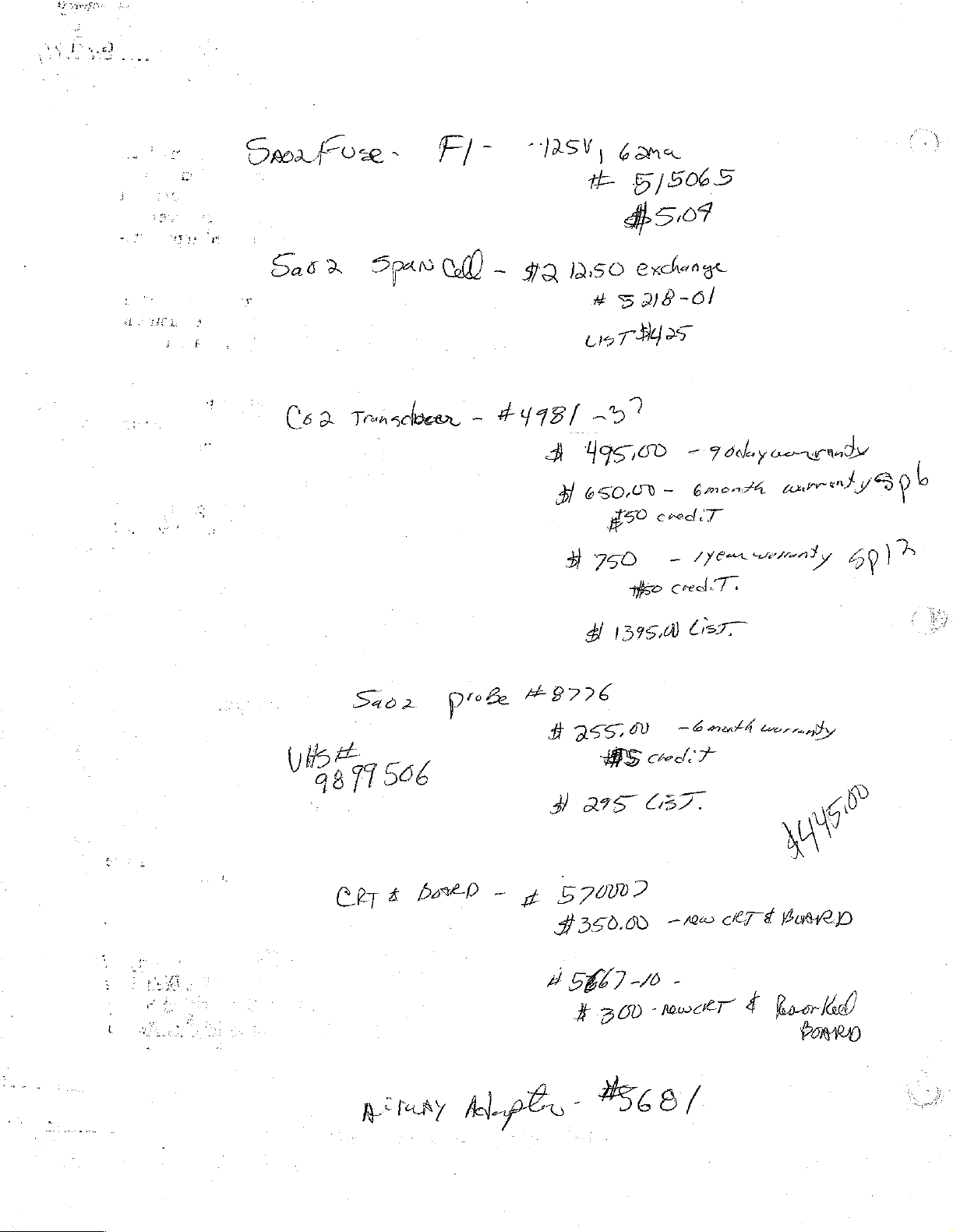
Spor
fose-
Fl"
"BSV;
Gama
5/5065
+
SOF
|
-
Saca
é
Cea
Span
GO
par
Truscbeer
Saoz
-
pré
PQ
~
+498
49776
ISO
ua
/
19500
A
65001-
JÍ
과
4
3
#
TİJ
Ab?
pee
750
1395)
exchenge
-01
9/8
—
coed
一
|
cred
ão
CET
delay
7
ömer
<7
Pyle
T.
asan
een
070"
591%
y
ete
bf
Va
so
TT
PRED
À
CRT
ponny
É
—
pÉs
pel
BASS
WS
BIS
|
Ga?
93550.00
GE)
4
ο...
#36
-
ced
CET
-/
8
бое
<8
-
/
ann,
ATİ
ン
yi
LAR
PARO
~
Page 3
Service
Manual:
Model
7000
Guarantee
Equipment
is
fully
guaranteed,
from
year
products
right
tion,
Novametrix’
Novametrix’
except
occur
Claims
portation
both
equipment.
Improper
out
release
with
to
perform
the
at
or
fuses,
during
for
company.
the
model
use,
following
Novametrix
manufactured
covering
of
date
the
stated
customer’s
obligations
option,
batteries,
normal
damages
mishandling,
guarantees
guarantee
replacement
service.
during
All
correspondence
name
specific
and
from
and
Guarantee
or
distributed
materials
shipment,
service(s)
installation.
under
calibration
number,
tampering
operating
further
any
except
other
this
of
shipment
and
instructions
guarantee
by
Novametrix
and
workmanship,
certain
for
than
one
at
its
factory,
guarantee
defective
any
gasses,
must
be
concerning
the
serial
with,
or
operation
obligations.
year.
at
are
limited
parts
without
filed
promptly
the
number
will
void
Coz
Medical
disposable
Novametrix
an
charge,
equipment
of
colt.
for
a
authorized
to
our
of
if
with
as
it
appears
the
equipment
this
guarantee
Systems
period
products
repairs,
of
reserves
repair
equipment,
said
defects
the
must
specify
on
Inc.,
one
and
the
sta-
or
at
trans-
the
with-
and
'
For
Caution:
by
or
This
Novametrix
retrieval
means,
Systems
Federal
on
the
document
system,
without
Inc.
Novametrix’
In
Connecticut,
(U.S.A.)
order
of a physician.
contains
Medical
Systems
translated,
prior
Service
factory
1-800-243-3444
call
Telex
Facsimile
law
restricts
information
Inc.,
transcribed,
explicit
written
Department
repair
Collect
956-054
(203)
which
and
service,
(203)
284-0753
this
device
is
proprietary
may
not
be
or
transmitted,
permission
265-7701
to
from
call
toll
free
sale,
distribution,
and
the
reproduced,
in
any
form,
Novametrix
or
use
property
stored
or
by
in
any
Medical
of
a
Novametrix
5007-90-P3
20-Jul-89
Page 4

Page 5
Service
Manual:
Model
7000
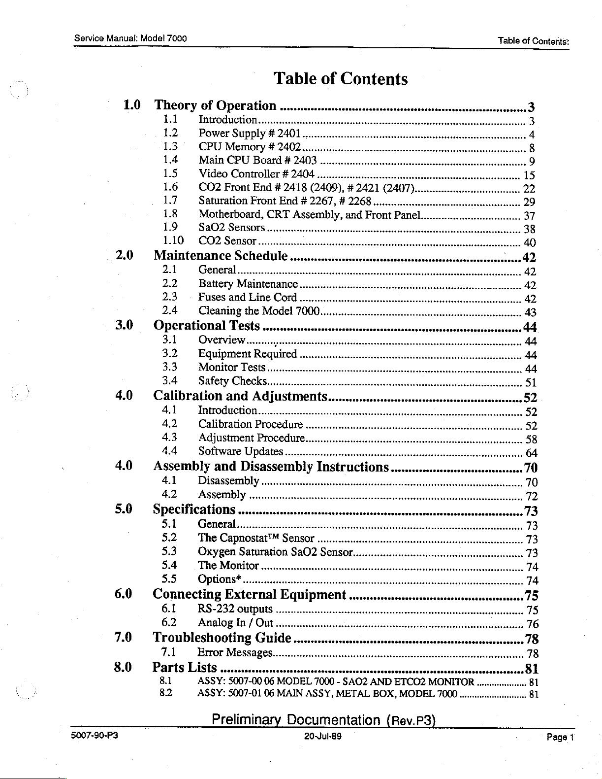
Table
of
Contents:
10
2.0
3.0
4.0
4.0
5.0
6.0
7.0
80
Table
Theory
11
1.2
1.3
1.4
1.5
1.6
1.7
1.8
19
110
Maintenance
21
2.2
2.3
2.4
。
Operational
3.1
3.2
3.3
3.4
Calibration
4.1
4.2
4.3
44
Assembly
4.1
42
|
Specifications..
5.1
5.2
5.3
5.4
55
Connecting
6.1
6.2
Troubleshooting
7.1
Partslists...............
8.1
8.2
of
Operation
Introduction.............
Power
CPU
MainCPUBoard#2403....................
VideoController#2404............................
CO2
Saturation
Motherboard,
SaO2
CO2
Supply
Memory
Front
Front
Sensors
Senmsor
..
#
2401.
#
2402................
End + 2418
End $ 2267, # 2268
CRT
nee
иьненииииолиизлинильзмишиниитоталили
Schedule..........
General....................
Battery
Fuses
Cleaning
OvervieW
Equipment
Monitor
Safety
A
Calibration
Adjustment
Software
Disassembly
Assembly
General........................
The
Oxygen
The
Optonst..........................
RS-232outputs..................
AnalogIn/Out........
20007
ASSY:
ASSY:
Maintenance
and
Line
Cord
the
Model
TeSS
Required
Tests.......
Checks.....................
and
Adjustments
Procedure
Updates...
and
Disassembly
CapnostatTM
Saturation
Monitor...
External
Guide
746668865.0.000
5007-00
5007-01
инь
Procedure.
ue
Sensor
SaO2
Equipment.
06
MODEL
06
MAIN
of
Contents
..
eserse
(2409), # 2421
Assembly,
and
(2407)
..............
Front
Panel..
ити
000
rennes
7000...
оноюонеиньзиононоьовавонотвотиниивиоиоини
ee
лилии
ee
ee
шииты,
ee
излить
scan
τος
cod
…
…
…
…
…
…
„8
9
38
40
42
42
42
43
44
44
44
44
51
...52
52
dre.
Instructions.
AN
…
52
.
58
.
64
70
.
70
72
73
…
73
...........
Sensor...
iii
.............asesesesesemes
아
나
아
이
아
아
아
아
아
아
아
아
이
아
7000
-
SAO2
AND
ASSY,
METAL
BOX,
아
아
마
ETCO2
eric
라
라
여
라
MODEL
erezioni
ee
아
아
아
아
어
MONITOR
7000
마
아
아
마
아
.
...........................
마
이
…
…
…
…
ninni
아
아
이
아
이
...
73
.
73
.74
74
73
75
76
78
이
78
81
..
81
81
5007-90-P3
Preliminary
Documentation
20-Jul-89
(Rev.P3)
Page
1
Page 6
Table
of
Contents:
Service
Manual:
Model
7000
9.0
8.3
84
8.5
8.6
8.7
8.8
8.9
8.10
8.11
8.12
8.13
8.14
8.15
8.16
8.17
8.18
8.19
8.20
8.21
8.22
8.23
8.24
8.25
ASSY:
ASSY:
ASSY:
ASSY:
ASSY:
ASSY:
ASSY:
ASSY:
ASSY:
ASSY:
ASSY:
ASSY:
ASSY:
ASSY:
ASSY:
ASSY:
ASSY:
ASSY:
ASSY:
ASSY:
ASSY:
ASSY:
ASSY:
Schematics
4977-13
2400-01
2402-01
2403-01
2404-01
2405-01
2407-01
2409-01
2418-01
2421-01
5006-01
5055-01
2267-01
2267-17
2268-01
2268-17
5088-01
5062-01
5007-06
4998-01
5013-01
4959-01
5218-01
and
Assembly
02
TOP
06
MOTHER
04
CPU
04
MAIN
04
VIDEO
05
RAM
03
FRONT
02
PIGGYBACK
04
PIGGYBACK
01
FRONT
03
POWER
04
REAR
03
Sa02
00
FNT
03
FRONT
00
FNT
06
BEZEL
00
SAO2
XX
OPTION
02
CO2
02
REGULATOR
03
SENSOR
02
SENSOR
COVER
MEMORY
SIMM
FRONT
END
END
INPUT
SCREENED,
BOARD
CPU
BOARD
CONTROLLER
BOARD
END
BD
BD
BOARD
END
BOARD
HARNESS
PANEL
ASSY,
INPUT
DIGITAL
END
ANALOG
LIST,
HARNESS,
CAL
CAL
ASSY,
END
ANALOG
MODEL,
HARNESS,
HARNESS
RCPT
RECEPTACLE
ASSY,
BOARD
ASSY,
ASSY,
ASSEMBLY
ASSY
ASSEMBLY,
ASSY,
ASSY,
MODEL
BD
ASSY,
BD
BD
MODEL
ASSY,
MODEL
MODEL
ASSY,
MODEL
BD
ASSY,
(CTC),
MODEL
ASSY...........................
BD
ASSY,
ASSY
7000
MOD
7000
MODEL
ASSY,
7000..
7000...
MODEL
MODEL
MODEL
(CTC),
1260......
MODEL
7000
7000...
MODEL
MODEL
......
7000.
........
7000
MODEL
1260...
ASSY,
7000
7000...
7000..........
MODEL
MO!
7000
....
7000.
7
7000..
7000.
MODEL
7000..
Drawing6s...........cseccscssssecscecsssceeseceees
Page
2
Preliminary
Documentation
20-Jul-89
(Rev.P3)
5007-90-P3
Page 7

Service
Manual:
Model
7000
Theory
of
Operation:Introduction
1.0
11
Theory
of
Introduction
The
Model
reliable
rate,
infra-red
A
requirements,
after
sent
the
five
along
panel
used
connections
ease
changing
backup
possible
continuous
expired
light
user
friendly
the
unit
is
There
monitor’s
The
are
Status
softkeys,
for
of
or
with
the
jacks
the
“SaO2
system,
are
disassembly.
unit
can
a
programming
will
supply
battery
Operation
7000
is a
non-invasive
measurement,
CO2,
and
respiratory
sources
once
turned
five
menu
operation.
power
Cal
damage.
and
menu
display
programmed
off.
“softkeys”
displayed,
The
switch
Cell
used
INPUT”
The
jacks
run
through
operate
from
key
approximately
monitoring,
rate.
computing
system
any
which
front
and
and
found
perform
this
panel
indicators,
in
calibrating
“CO2
are
different
the
system’s
any
voltage
in
1
hour
portable
This
the
assists
changes
eliminates
is
Sa02/ETCO2
is
results
different
a
membrane
the
the
INPUT”
to
avoid
Motherboard
and
the
power
of
operation
and
display
performed
to
acquire
in
programming
are
permanently
commands
large
are
confusing
switch
ALERT
Capnostat™
for
the
connection
frequency
entry
module
with
monitor
of
by
the
overlay
RESET
(202
designed
oxygen
analyzing
correct
the
stored
depending
keypanels
and
sensor.
connection
of
the
via
removable
found
protection
on
in
the
the
rear
to
saturation,
the
changes
parameter
unit
for
in
memory
upon
and
which
of
circuitry
contains
AUDIO
The
the
two
wrong
world
sensor.
connectors
panel.
produce
pulse
in
results.
individual
even
the
pre-
simplifies
the
buttons,
two
front
sensors
All
for
by
simply
A
battery
to
prevent
The
monitor
to
as
the
functions
nicates
lines
The
tions,
Manual.
with
are
CRT
Various
The
different
*
2401
*
2402
*
2403
*
2404
*
2421
*
2418
*
2267
+
2268
+
Motherboard
is
“host”.
through
external
run
through
displays
displays
assemblies
Power
CPU
Main
Video
Digital
Analog
Digital
Analog
controlled
Consider
communication
equipment
the
the
by
the
Motherboard
waveforms
are
found
Supply
Memory
CPU
Board
Board
Board
Controller
CO2
Front
CO2
Front
SaO2
Front
SaO2
Front
the
Motorola
host
as
the
with
each
through
where
as
selected
available,
in
the
Model
-
End
Board
End
Board
End
Board
End
Board
MC68000
“brains”
board,
the
each
runs
rear
panel
all
the
by
the
is
described
7000
are
(previously
(previously
Microprocessor
of
the
system,
the
system
connectors.
individual
user
along
thoroughly
listed
below:
2407)
2409)
it
controls
software,
All
circuit
boards
with
which
the
in
is
referred
all
internal
and
commu-
communication
are
housed.
softkey
the
Operating
func-
5007-90-P3
Preliminary
Documentation
20-Jul-89
(Rev.P3)
Page
3
Page 8
¿Theory
of
Operation:Power
+
*
Supply
CRT
Front
#
2401
Assembly
Panel
Membrane
Switch
Overlay
Service
Manual:
Model
7000
1.2
Power
1.2.1
There
supply.
they
are
the
monitor.
or
even
it
is
used
used
to
within
1.22
AC
acceptable
AC/DC
The
power
AC
Plugged
*
Supply # 2401
Output
Three
charge
1260/7000
operation
level.
Both
voltages
are
four
used
to
Even
device
to
power
line
the
low
of
these
power
small
failure.
the
the
battery.
limits
operation
monitor
or
in
DC
mode
into
a
line
cord and
level
DC
voltages
critical
deviations
The
CRT
so
fourth
picture
While
that
the
digital
can
mode
occurs
properly
with
when
fuses
voltages
(+5V,
and
from
voltage
tube
this
voltage
components
operate
wired
either
its
internal
the
monitor
AC
are
in
supplied
+15V,
analog
their
(V
BAT)
and
operate
in
battery.
line
good
condition,
as
-15V)
components
nominal
need
the
fan,
may
be
properly.
AC
mode
is:
with
outputs
need
to
values
not
and
under
less
regulated
by
an
acceptable
and
from
be
closely
which
may
lead
be
as
tightly
AC
an
external
the
1260/7000
regulated
make
up
to
erroneous
regulated
operation
it
must
connection
operating
power
the
heart
mode
still
be
voltage
since
of
data
since
is
kept
to
an
+
the
rear
DC
operating
*
unit
is
operating
*
Power
*
AC
line
*
the
rear
While
operating
charged.
ating
operating
introduced
information
panel
1.2.3
The
battery
the
mode
As
level,
mode
into
occurs
indicates
DC
power
power
from
panel
mode
unplugged
level.
cord
and/or
power
panel
monitor
are
soon
as
or
the
is
the
monitor,
when
that
AC
source
source
being
power
power
met,
the
unit
automatically
entry
occurs
from
fuse
is
lost,
or
entry
is
connected
the
AC
line
is
turned
AC
switch
when
the
are
bad.
switch
monitor
voltage
initiated.
operating
switching
power
for
ruined
is
present.
the
DC
by a deep
is
set
either:
AC
line
is
set
to
an
acceptable
operates
into
on
while
mode
between
mode
is
discharge
ON
or
the
to
OFF
in
the
not
When
is
AC
and
the
internal
(|).
AC
voltage
(0).
AC
source
AC
mode
monitor
falls
connected
an
acceptable
restored.
DC
modes.
lead
under
DC
is
below
and
the
and
the
below
to
an
AC
AC
No
loss
of
The
AC
acid
battery.
operation,
an
acceptable
conditions
internal
the
acceptable
line
source,
line
is
once
monitor
LED
the
function
on
To
prevent
power
for
AC
battery
oper-
DC
again
the
front
the
supply
is
or
Page
4
Preliminary
Documentation
20-Jul-89
(Rev.P3)
5007-90-P3
Page 9
Service
Manual:
turns
warning
provide
up
volts
Model
7000
the
the
power,
when
monitor
is
provided
battery
a
constant
it
is
fully
of
when
to
alert
with
voltage
charged
battery
a
quick
down
voltage
the
user
charge
charging
to
before
while
method
the
turn
falls
to
a
the
turn
off
maintaining
is
used.
off
threshold
Theory
preset
of
threshold.
threshold
stand-by
The
battery
of
10.5
Operation:Power
A
“Low
is
actually
float
current
delivers
VDC.
between
Supply
#
2401
Battery”
reached.
for
To
back-
13.8
1.24
how
users.
changing
also
normal
erated
120
1.2.5
RAW
from
DC/BATTERY
SWITCH
MONITOR
whether
CONVERTER.
the
front
SIGNAL
ER,
and
DC
POWER
AC
AC
power
well
the
The
the
required
power
by
the
-
10%
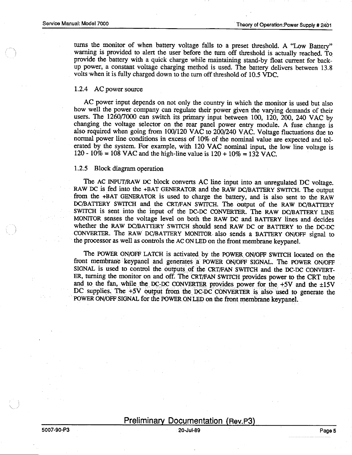
Block
The
AC
DC
is
the
+BAT
is
the
processor
The
POWER
membrane
is
turning
to
the
supplies.
ON/OFF
power
1260/7000
source
input
power
voltage
when
line
system.
=
108
VAC
diagram
INPUT/RAW
fed
into
GENERATOR
SWITCH
sent
into
senses
RAW
The
as
well
ON/OFF
the
DC/BATTERY
RAW
keypanel
used
to
the
monitor
fan,.while
The
SIGNAL
depends
company
can
selector
going
conditions
For
and
operation
the
and
the
voltage
as
on
switch
from
example,
the
DC
block
+BAT
the
input
DC/BATTERY
controls
LATCH
and
control
+5V
on
the
DC-DC
output
for
the
the
and
not
only
can
regulate
its
primary
on
the
rear
100/120
in
excess
with
high-line
converts
GENERATOR
is
used
to
CRT/FAN
of
the
level
on
both
SWITCH
MONITOR.
the
AC
ON
is
activated
generates
outputs
off.
from
POWER
of
The
CONVERTER
the
ON
the
country
their
input
panel
VAC
to
of
10%
120
VAC
value
is
AC
and
charge
SWITCH.
DC-DC
the
should
LED
by
a
POWER
the
CRT/FAN
DC-DC
LED
on
in
which
power
given
between
power
200/240
of
the
nominal
nominal
120
+
10%
line
input
the
RAW
the
battery,
The
CONVERTER.
RAW
DC
send
RAW
also
sends
on
the
front
the
POWER
ON/OFF
CRT/FAN
SWITCH
SWITCH
provides
CONVERTER
the
front
the
monitor
the
varying
100,
entry
VAC.
DC/BATTERY
output
module.
Voltage
value
input,
=
132
VAC.
into
an
unregulated
and
is
of
The
and
BATTERY
DC
or
a
BATTERY
membrane
ON/OFF
RAW
SIGNAL.
and
provides
power
for
is
also
membrane
is
demands
120,
200,
A
fuse
fluctuations
are
expected
the
low
SWITCH.
also
sent
the
RAW
DC/BATTERY
lines
BATTERY
ON/OFF
keypanel.
SWITCH
The
POWER
the
DC-DC
power
the
to
+5V
used
to
keypanel.
used
but
of
240
VAC
change
due
and
line
voltage
DC
voltage.
The
output
to
the
DC/BATTERY
and
decides
to
the
DC-DC
signal
located
on
ON/OFF
CONVERT-
the
CRT
and
the
generate
also
their
by
is
to
tol-
is
RAW
LINE
to
the
tube
+15V
the
5007-90-P3
Preliminary
Documentation
20-Jul-89
(Rev.P3)
Page
5
Page 10
>
Theory
of
Operation:Power
Supply
#
2401
Service
Manual:
Mode!
7000
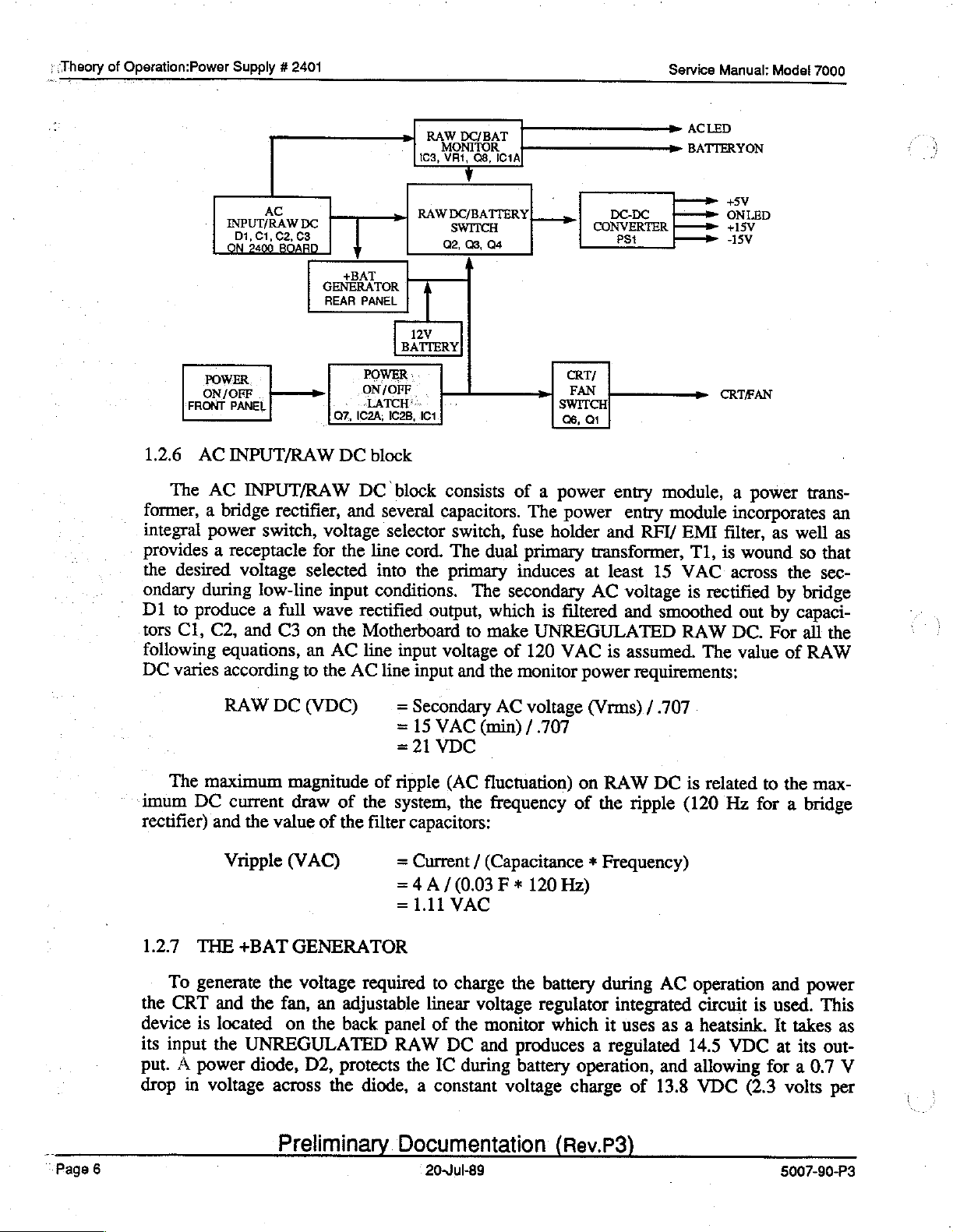
INPUT/RAW
POWER
ON/OFF.
FRONT
1.2.6
former,
integral
provides
the
ondary
D1
tors
following
DC
ACINPUT/RAW
The
AC
a
bridge
power
a
desired
during
to
produce
Cl,
C2,
equations,
varies
AC
D1,
ON
PANEL
INPUT/RAW
receptacle
voltage
and
according
DC
C1,
C2,
2400
C3
BOARD
———>
rectifier,
switch,
low-line
a
full
C3
+BAT
GENERÁTOR
REAR
PANEL
ON/OFF
>
07.
1024, IC2B,
DC
DC
and
voltage
for
the
selected
input
wave
rectified
on
the
Motherboard
an
AC
to
the
AC
RAW
MONITOR
ca,
RAWDC/BATTERY|__
02,
12V
BATTERY
POWER:
|
LATCH
+
IC1
block
block
several
selector
line
into
conditions.
line
line
capacitors.
cord.
the
output,
input
voltage
input
DC/BAT
G8,
СЧА
”|
VAL,
Y
SWITCH
2
08,
04
consists
switch,
The
dual
primary
The
which
to
make
of
and
the
——1——_—_———,
:
y]
of
The
fuse
primary
induces
secondary
120
monitor
CRT/
>|
FAN
SWITCH
06,
a
power
power
holder
is
filtered
UNREGULATED
VAC
DC.DC
CONVERTER
PS1
O1
entry
entry
and
transformer,
at
least
AC
voltage
and
is
power
—*
module,
module
RFI/
15
smoothed
assumed.
requirements:
ACLED
BATTERYON
Lo
==»
pa
+5v
ONLED
+15V
-15V
CRTÆAN
EMI
filter,
T1,
is
VAC
is
rectified
RAW
The
a
incorporates
wound
across
out
DC.
value
power
as
the
by
by
For
of
trans-
an
well
as
so
that
sec-
bridge
capaci-
all
the
RAW
“Page
6
RAW
The
maximum
imum
rectifier)
12.7
the
device
its
DC
THE
To
generate
CRT
is
input
current
and
Vripple
+BAT
and
located
the
put. A power
drop
in
voltage
DC
(VDC)
magnitude
draw
of
the
value
of
the
(VAC)
GENERATOR
the
voltage
the
fan,
an
adjustable
on
the
back
UNREGULATED
diode,
D2,
across
protects
the
Preliminary
=
Secondary
=
15
VAC
=21
VDC
of
ripple
the
system,
filter
=
=4A/(0.03
=
required
(AC
capacitors:
Current / (Capacitance * Frequency)
1.11
to
linear
panel
RAW
the
of
DC
IC
diode, a constant
AC
(min)
fluctuation)
the
frequency
F *
VAC
charge
voltage
the
monitor
and
during
voltage
Documentation
20-Jul-89
voltage
(Vrms) / .707
/.707
on
120
Hz)
the
battery
regulator
which
of
RAW
the
during
it
DC
ripple
AC
integrated
uses
as a heatsink.
produces a regulated
battery
operation,
charge
of
and
13.8
(Rev.P3)
is
related
(120
Hz
operation
circuit
14.5
is
VDC
allowing
VDC
(2.3
to
the
max-
for
a
bridge
and
power
used.
It
takes
at
its
for a 0.7
volts per
5007-90-P3
This
as
out-
V
Page 11
Service
Manual:
Modei
7000
Theory
of
Operation:Power
Supply
#
2401
battery
the
1.2.8
tion
volt
voltage
mary
switches
provided
also
from
lower
itor
that.
Taking
cell)
condition
AC/BATTERY
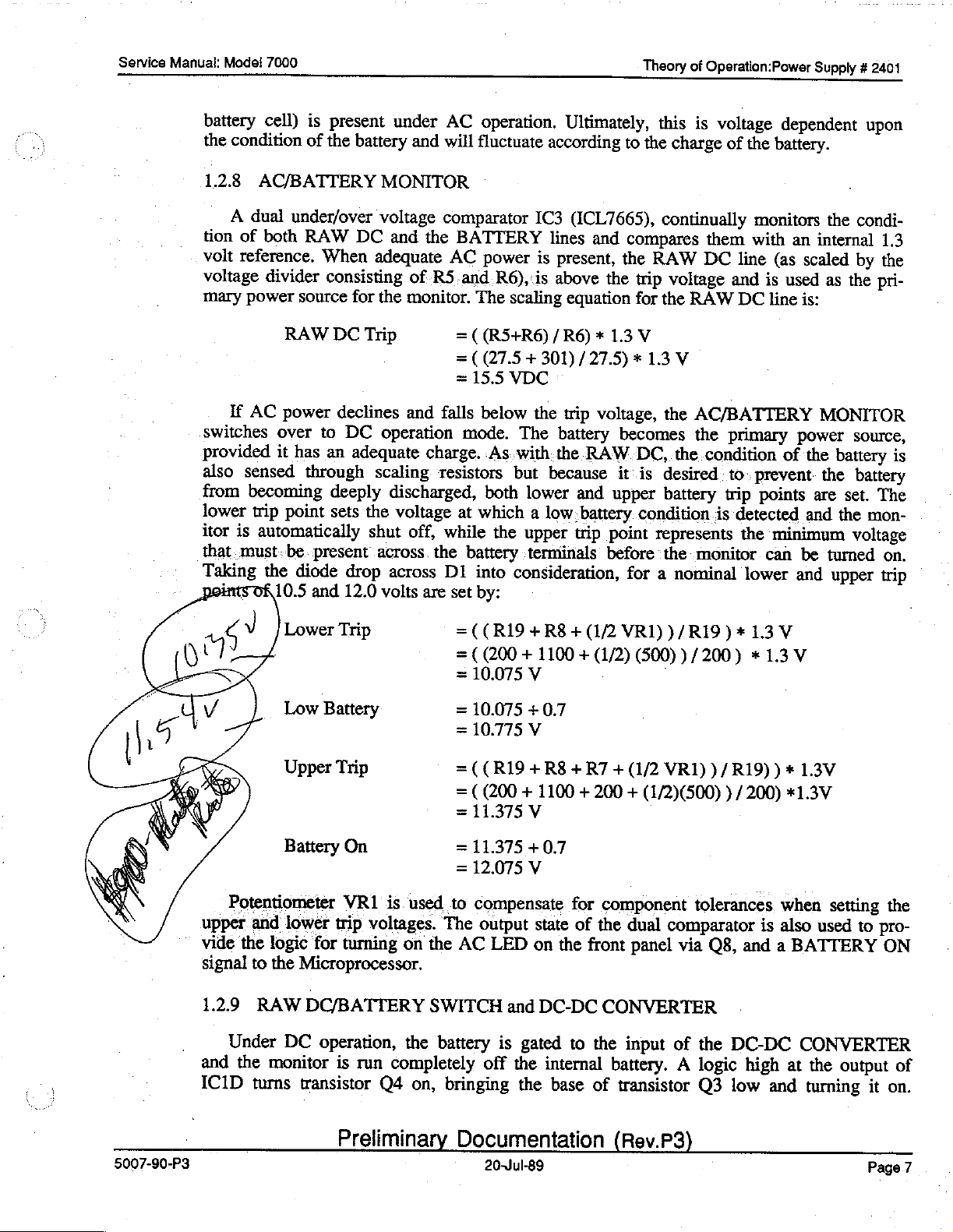
A
dual
of
both
reference.
divider
power
If
AC
sensed
becoming
trip
is
automatically
must:
the
ints
0f10.5
is
present
of
the
under/over
RAW
When
consisting
source
RAW
power
over
it
DC
declines
to
has
an
through
deeply
point
sets
be.
present’
diode
and
Lower
Trip
under
battery
MONITOR
voltage
DC
and
adequate
for
the
Trip
DC
operation
adequate
scaling
discharged,
the
voltage
shut
across.
drop
across
12.0
volts
AC
operation.
and
will
fluctuate
comparator
the
BATTERY
AC
power
of
R5.and-R6),:is
monitor.
The
= ( (R5+R6) / R6) * 1.3
=((27.5+
=
15.5
and
falls
below
mode.
charge.
resistors
As.with.the
both
at
which
off,
while
the
D1
are
the
battery
into
set
by:
=((R19+R8+(1/2VR1))/R19)+13V
= ( (200 + 1100 + (1/2)
=
10.075
Ultimately,
according
IC3
(ICL7665),
lines
and
is
present,
above
scaling
301)
the
equation
/27.5)*
VDC
the
trip
voltage,
The
battery
but
because
lower
a
low
upper
-terminals
consideration,
becomes
RAW
it
and
upper
battery
trip
point
before
V
this
is
voltage
to
the
charge
continually
compares
the
RAW
trip
voltage
for
the
V
1.3
V
the
DC,.the.condition
is
desired
battery
condition.
represents
the
for
a
nominal
(500)
)/
of
the
them
DC
line
and
RAW
DC
AC/BATTERY
the
primary
to-
trip
is
detected
the
monitor
lower
200) * 1.3
|
dependent
battery.
monitors
with
an
(as
scaled
is
used
line
is:
power
of
the
prevent
points
can
are
and
minimum
be
and
V
upon
the
condi-
internal
by
the
as
the
pri-
MONITOR
source,
battery
the
battery
set.
The
the
mon-
voltage
turned
upper
trip
1.3
is
on.
5007-90-P3
Low
Upper
Battery
Potentiometer
upper
vide
signal
1.2.9
and
ICID
and
the
logic
to
the
RAW
Under
the
monitor
turns
lower
DC
Battery
Trip
Оп
VR1
is
used
trip
voltages.
for
tuming
Microprocessor.
DC/BATTERY
operation,
is
run
transistor
Preliminary
on
the
SWITCH
the
completely
Q4
on,
=
10.075 + 0.7
=
10.775
=
(CR19
V
+R8 + R7 + (1/2
VR1)
= ( (200 + 1100 + 200 + (1/2)(500) ) /
=
11.375
=
11.375
=
12.075
to
compensate
The
output
AC
battery
bringing
Documentation
У
+07
У
state
LED
on
and
DC-DC
is
gated
off
the
the
20-Jul-89
for
component
of
the
the
front
CONVERTER
to
the
internal
base
battery.
of
(Rev.P3)
tolerances
dual
comparator
panel
input
transistor
via
of
A
the
logic
Q3
}/
R19) ) *
Q8,
and
DC-DC
high
low
200)
is
also
a
and
1.3V
*1.3V
when
setting
used
BATTERY
CONVERTER
at
the
output
turning
to
pro-
it
Page
the
ON
of
on.
7
Page 12
Theory
of
Operation:CPU
Memory # 2402
Service
Manual:
Model
7000
Transistor
switch
power
transistor
VERTER.
convert a 9
efficiency
from
nal
1.2.10
the
associated
line.
in
sideration
directly
1.2.11
closure
whose
flip-flop
this
the
tion
ON/OFF
Capacitor
for
from
ICIC,
the
monitor
CRT/FAN
To
avoid
CRT
Because
the
switch
off
POWER
The
POWER
ofthe
width
(IC2A),
pulse
present
is
detected
switch
of
and
LATCH
power-up.
Q3
then
the
battery
leaking
Q2
The
DC-DC
to
24
volt
about
the
75%.
POWER
is
on
SWITCH
the
loss
the
fan
circuitry
given
of
the
FET
and
the
IC1B
is
wasted
of
ON/OFF
ON/OFF
front
is
controlled
and a short
causes
state
the
until
by
will
C2
and
resistor
turns
into
back
is
off
CONVERTER
input
The
ON / OFF
via
the
of
require
used
has
high
the
panel
output
the
the
be
power
into
efficiency
to
when
POWER
transistor
the
CONVERTER.
the
and
D3
into
tightly
outputs
ON LED
only loosely
supply
very
low
the
power
ON/OFF
LATCH
LATCH
POWER
by
capacitor
pulse
of
the
next
positive
RAW
DC/BATTERY
forced
R17
cause
Q2
fully
on,
Back
RAW
LATCH.
when
CRT
requirements
DC
line.
is
forward-biased,
is a 50
regulated
of
the
located
going
the
CRT
resistance
tube
Watt
converter
The
on
the
through
regulated
display
when
and
of the
When
switching
+5,
are
+5v
supply
front
input
and
fan
LATCH.
receives
key,
is
generated
second D flip-flop
to
the
its
‘which:
Cl
and
clock
OFF
the
LATCH
control
appears
resistor
at
the Q not
edge.
MONITOR,
state
In
by
to
and
it
acts
biased
sending
+15,
panel.
turned
are
from a pulse
at
(IC2B)
the
diode
adequate
RAW
and
-15
enabled
line
the
DC-DC
power,
the
fan
on,
on,
which
CRT.
‘the
R3,
The
‘colle¢tor
is
debounced
output.
to
event
the
power
directly
with
very
toggle
that.a
transistor
be
reset
in
as a low
D3
prevents
RAW
DC
onto
supply
VDC
FET
directly
output
Q5
outputs
by
R25
Converter
switch
from
little
is
an
switch
generated
of
The
positive
and
low
of
and
the
OFF’
impedance
DC
is
present,
the
which
with
an
ON
is
used
and
Ol
the
power
important
is
controlled
during
Q7.
This
by
the
edge
to
latch
battery
the
POWER
resistor
state
battery
CON-
can
an
signal
to
sig-
since
and
its
+BAT
is
lost
con-
the
pulse,
first
D
of
onto
condi-
R13.
during
13
Page
8
CPU
1.3.1
age,
information.
per
(128K X 8)
up
low
1.3.2
inputs
transition
Memory
Memory
Two
types
and
SRAM
The
byte
(128K X 8)
and
in a similar
and
high).
Analog
The
analog
at a time.
of the
#
2402
of
memory
(SIMM
SRAM
is
and
is
enabled
manner.
to
Digital
to
When
LBWE
U2
Converter
digital
converter IC35
the
line.
Preliminary
devices
are
boards)
contained
is
enabled
by
the
which
CS11
Data
consists
line
lines
Documentation
used,
EPROM
for
temporary
on
two
2405-01
by
the
UBRE
LBRE
line.
of
two
The
has a multiplexed
is
low
IC49
D@-D3
20-Jul-89
feed
(IC2,
storage
SIMM
line,
EPROM
chips
(low
will
IC49
(Rev.P3)
3,
the
other
and
input
be
enabled
which
4,
and
5)
of
variables
boards,
handles
devices
high),
which
on
transfers
for
program
and
one
handles
the
IC2-IC5
and
U3
reads
the
positive
the
trending
the
lower
are
broken
(two
chips,
one
of
data
to
5007-90-P3
stor-
up-
byte
four
going
the
Page 13

Service
Manual:
Model
7000
Theory
of
Operation:Main
CPU
Board
#
2403
1.4
multiplexor
amplified
monitoring
IC35.
and
Main
1.4.1
The
MHz
program
peripheral
the
rest
packets
bits
16
Mbytes
protocol.
The
external
tions
by
CPU
The
heart
for
earlier
instruction
affected
of
the
that
of
the
MC68000
hardware
are
conducted
R/W
data
W=Write,
device.
1C34
is
(which
IC28A
handled
pin
by
1
IC28C
Board # 2403
Microprocessor
if
the
system
units).
system
are
either
word)
of
continuous
(Read/Write)
to
and
by
in
length
has
and
in
be
The
interpreting
the
via
one
various
the
a
smooth
sent
data
selects
and
instruction
a
word
memory
one
IC28B
pin
is
the
MC68000
16-bit
and
data
(the
a
24-bit
of
pin
8.
Motorola
oversees
it
to
of
full
space.
control
microprocessor
and
orderly
indicates
external
be
the
sent
from
from
to
four
7,
IC28D
IC41
deciding
its
task.
bus,
which
16-bits)
address
The
lines
to
manner:
the
direction
the
analog
develops
MC68000
Front
which
ensure
inputs).
pin
14
a
all
aspects
what
The
microprocessor
allows
or
one
bus
that
End
provide
that
of
device
microprocessor
to
The
is
a
spare
-10
volts
MPU
which
of
the
action
to
information
byte
(either
allows
Boards
“handshaking”
data
transfer
data
transfer.
microprocessor.
the
to
two
analog
input.
VREF
system,
take
the
communicate
the
Battery
for
runs
at
from
and
informing
communicates
to
be
the
high
processor
and
R=Read,
external
inputs
are
voltage
use
by
IC28
10
MHz
fetching
transferred
or
to
by
between
system
(8
the
with
in
low
8-
access
serial
the
func-
a
AS
(Address
placed
start
of a data
UDS,
LDS
length
ed
along
the
LBWE
DTACK
device
by
the
microprocessor
Strobe)
on
the
address
transfer
are
Upper
of
the
packet
with
R/W
by
(Lower
LDS:
information,
UDS:
ignore
UDS
information.
(Data
addressed
only
only
the
and
Byte
the
the
the
lower
LDS
Transfer
by
indicates
bus
by
the
cycle.
and
Lower
of
data
to
be
IC31,
Write
lower
upper
Enable),
byte
8-bits
upper
IC32B,
8-bits
8-bits.
together:
the
microprocessor
has
been
the
ACKnowledge),
received
that a valid
microprocessor
Data
Strobes,
transferred.
IC30C,
UBWE
of
the
data
should
contain
full
data
by
These
and
word
be
ignored.
valid
word
sent from
to
signal
the
device.
address
and
they
has
signals
indicate
signals
IC36F
contains
to
valid
information,
contains
the
that
the
data
been
the
the
are gat-
develop
valid
external
sent
5007-90-P3
Preliminary
Documentation
20-Jul-89
(Rev.P3)
Page
9
Page 14
Theory
of
Operation:Main
CPU
Board # 2403
Service
Manual:
Model
7000
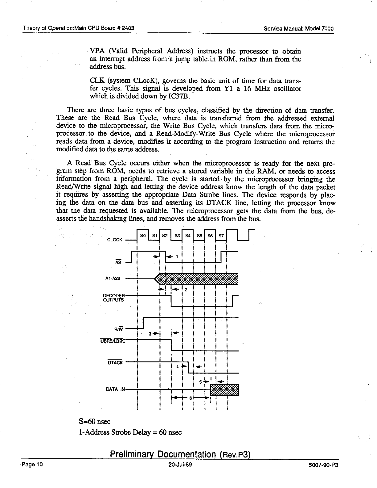
VPA
an
address
CLK
fer
which
There
These
device
processor
reads
modified
A
gram
information
Read/Write
it
requires
ing
that
asserts
are
to
data
Read
step
the
the
the
are
the
the
to
from a device,
data
Bus
from
from a peripheral.
signal
by
data
data
handshaking
(Valid
interrupt
(system
cycles.
is
three
Read
microprocessor,
the
device,
to
the
Cycle
ROM,
asserting
on
the
requested
CLOCK
Peripheral
address
bus.
This
divided
basic
Bus
same
occurs
needs
high
and
the
data
is
lines,
CLocK),
signal
down
types
Cycle,
and a Read-Modify-Write
modifies
address.
letting
appropriate
bus
available.
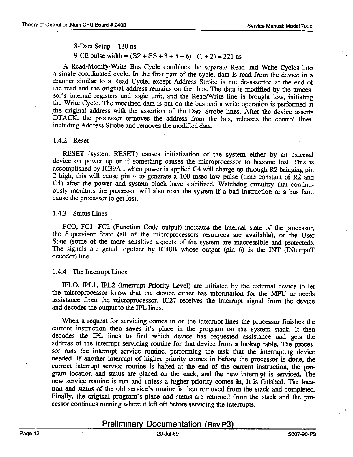
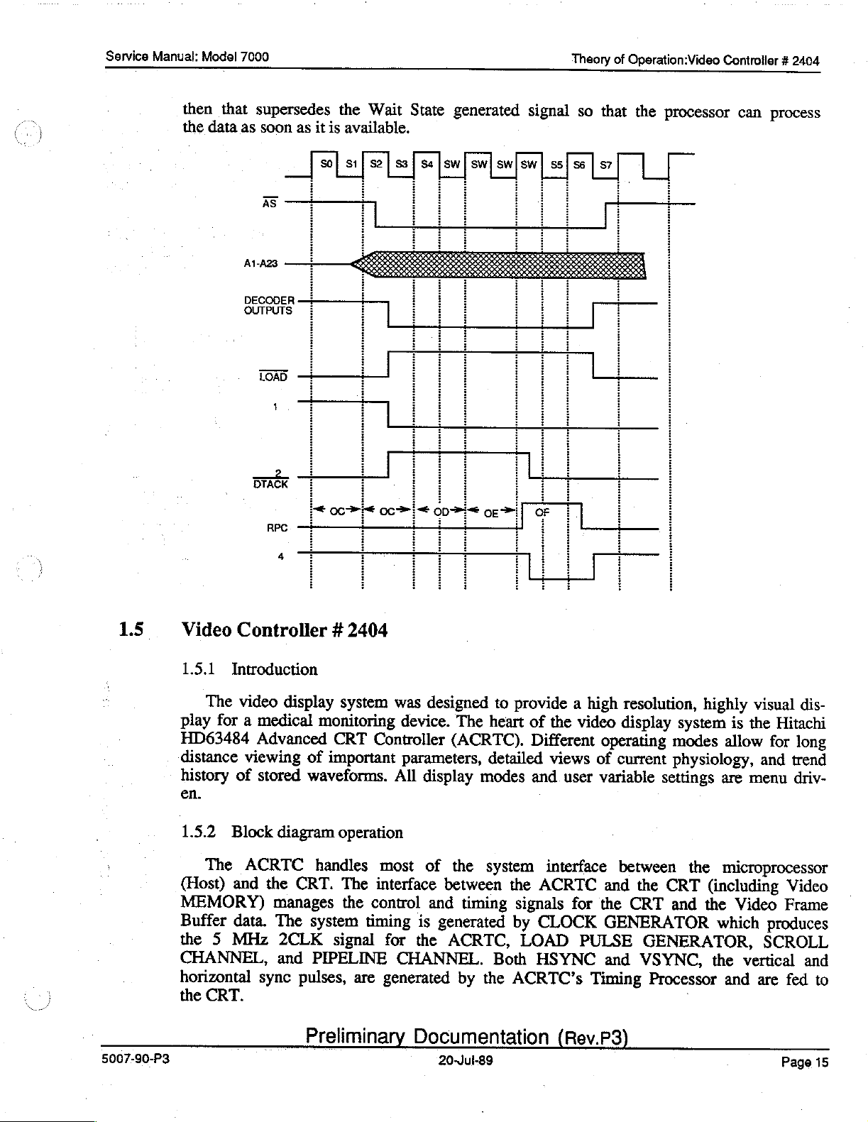
$0 | $1|
Address)
from a jump
governs
is
developed
by
IC37B.
of
bus
cycles,
where
the
Write
either
to
retrieve a stored
The
and
asserting
and
removes
52 | S3|
data
Bus
it
according
when
cycle
the
device
Data
The
microprocessor
the
S4 | 55]
instructs
table
in
ROM,
the
basic
unit
from
classified
is
transferred
Cycle,
to
the
the
microprocessor
variable
is
started-by
address
Strobe
its
DTACK
address
S6 | S7
the
of
Y1 a 16
by
which
Bus
Cycle
program
in
the
know
lines.
line,
gets
from
the
processor
rather
time
the
from
transfers
the
microprocessor
the
The
letting
the
bus.
|
to
than
from
for
data
MHz
where
instruction and
is
oscillator
direction
the
addressed
data
the
ready
RAM,
length
device
the
data
or
of
responds
from
obtain
the
trans-
of
data
transfer.
external
from
the
micro-
microprocessor
returns
for
the
next
needs
the
processor
to
access
bringing
data
packet
by
plac-
know
the
bus,
the
pro-
the
de-
DATA
S=60
nsec
1-Address
IN
Strobe
Delay = 60
nsec
Page
10
Preliminary
Documentation
20-Jul-89
(Rev.P3)
5007-90-P3
Page 15
Sarvice
Manual: Model
7000
Theory
of
Operation:Main
CPU
Board
#
2403
2-Decoder
3-UBRE/LBRE
4-DTACK
5-Data
6-Memory
A
Write
RAM
Address
on
into
asserting
address
or
the
the
Strobe
data
addressed
and
Setup
Bus
wants
bus
DTACK
data
Prop
Delay = 3
Prop
Setup = 20
Time = 15
Access
Cycle
to
send
is
asserted,
and
the
device.
and
from
their
CLOCK
AS
A1-A23
DECODER
OUTPUTS
decoder
Delay = Add
nsec
nsec
Time
=
S2+
occurs
data
the
when
to
a
the
Read/Write
appropriate
After
processor
busses.
So | $11
|
—
delays = 21
Strobe
53
+
54
the
microprocessor
peripheral.
Data
successfully
clears
52 | $3]
1
ke
È
a
line
Strobes
1
After
$4 | $5]
ns
Delay + Dec
+
55
+
56
the
is
brought
are
receiving
the
control
$6157
9
>
Prop
-
3
-
5
=
needs
address
asserted,
the
to
is
low.
data,
signals,
—
Delay = 67
218
ㅁ
560
store
a
variable
placed
The
writing
the
Г
on
data
the
device
finally
ns
in
the
bus
is
then
placed
information
responds
removing
the
and
by
the
UDS/LDS
LBWE/UBWE
DATA
S=60
nsec
1-Address
2-Decoder
3-UDS/LDS
4-R/W
5-LBRE/UBRE
6-LBRE/UBRE
Strobe
Prop
from
S2 = 70
ΒΑΝ.
DTACK
OUT
Delay = 60
Delay = 21
from
S4 = 60
prop
pulse
3İ
mİ
Fe
4>
8—>
ns
delay = 7
width = 115
ns
ns
~
5
7—>|
ei
nsec
ns
ns
6
—
5007-90-P3
7-DTACK
setup = 130
Preliminary
ns
Documentation
20-Jul-89
(Rev.P3)
Page
11
Page 16
Theory
of
Operation:Main
CPU
Board
#
2403
Service
Manual:
Model
7000
8-Data
9-CE
A
Read-Modify-Write
a
single
manner
the
sor’s
the
the
DTACK,
including
1.4.2
device
accomplished
2
high,
C4)
ously
cause
143
coordinated
similar
read
and
internal
Write
original
RESET
Cycle.
the
Address
Reset
on
power
this
after
the
monitors
the
processor
Status
(system
will
Setup = 130
pulse
width = (S2 + S3.+3+5+6)-(1+2)=221
to
a
the
original
registers
The
address
processor
Strobe
up
by
IC39A
cause
power
the
processor
to
Lines
ns
Bus
cycle.
Read
In
Cycle,
address
and
logic
modified
with
the
removes
and
RESET)
or
if
something
,
when
pin
4
and
system
get
lost.
Cycle
the
first
except
remains
unit,
data
is
assertion
the
removes
causes
power
to
generate
clock
will
also
combines
part
Address
on
and
put
on
of
address
the
modified
initialization
causes
is
applied
a
have
reset
the
of
the
cycle,
Strobe
the
bus.
the
Read/Write
the
bus
the
Data
from
data.
the
microprocessor
C4
100
msec
stabilized.
the
system
separate
data
is
The
data
and
a
write
Strobe
the
bus,
of
the
will
charge
low
pulse
Watchdog
if
a
ns
Read
is
read
not
de-asserted
is
modified
line
is
operation
lines.
system
After
releases
to
up
through
(time
bad
instruction
and
Write
from
the
by
brought
either
become
low,
is
the
the
by
R2
constant
circuitry
Cycles
device
at
the
end
the
proces-
initiating
performed
device
control
that
or
asserts
an
external
lost.
This
bringing
of
R2
continu-
a
bus
into
in
a
of
at
lines,
is
pin
and
fault
FCO,
the
State
The
decoder)
1.4.4
IPLO,
the
assistance
and
When
current
decodes
address
sor
needed.
current
gram
new
tion
Finally,
cessor
FC1,
Supervisor
(some
signals
line.
The
IPL1,
microprocessor
from
decodes
a
instruction
the
of
runs
the
If
interrupt
location
service
and
status
the
continues
FC2
State
of
the
are
gated
Interrupt
IPL2
the
the
output
request
for
then
IPL
lines
the
interrupt
interrupt
another
interrupt
service
and
status
routine
of
the
original
running
(Function
(all
more
together
Lines
(interrupt
know
Code
of
the
microprocessors
sensitive
by
Priority
that
the
aspects
device
microprocessor.
to
the
IPL
lines.
servicing
saves
to
servicing
service
routine
are
is
run
and
old
service’s
program’s
where
comes
it’s
find
which
routine
routine,
of
higher
is
placed
unless
place
it
left
halted
routine
output)
of
IC40B
IC27
place
whose
Level)
either
receives
in
on
in
device
for
performing
priority
at
on
the
a
higher
is
and
status
off
before
indicates
resources
the
system
output
are
initiated
has
the
the
interrupt
the
program
has
that
device
the
comes
the
end
stack,
and
priority
then
removed
are
returned
servicing
the
internal
are
are
inaccessible
(pin
6)
by
the
information
interrupt
lines
the
on
the
requested
from
a
lookup
task
that
in
before
of
the
the
comes
the
current
new
interrupt
in,
from
from
the
interrupts.
state
of the
available),
and
is
the
INT
external
for
the
MPU
signal
from
processor
system
assistance
stack.
and
table.
the
interrupting
processor
instruction,
is
it
is
finished.
the
stack
and
the
stack
processor,
or
the
User
protected).
(INterrpuT
device
finishes
The
or
the
device
It
gets
proces-
to
needs
the
then
the
device
is
done,
serviced.
The
the
the
pro-
The
loca-
completed.
and
the
pro-
let
Page
12
Preliminary
Documentation
20-Jul-89
(Rev.P3)
5007-90-P3
Page 17
Service
Manual:
Model
7000
Theory
of
Operation:Main
CPU
Board # 2403
1.4.5
Kilobytes
long-life
keep
providing
SRAM
monitor
this
viously
1.4.6
mation
volts.
nels
addressing
low
and
or
1.4.7
Timekeeper
The
Timekeeper
of
lithium
any
information
is
is
way,
each
set
Digital
The
D-to-A
from
The
from
which
16
respectively)
Vd
(pins
Dual
RAM
RAM
low
power
battery,
stored
time
and
date
also
used
to
turned
are
AD7226KN
a
IC26
activates
2,
on,
time
the
maintained
to
Analog
Converter
the
digital
shared
1,
time-multiplexed
which
the
steer
20,
19
Asynchronous
IC14
CMOS
and
stamping
remember
the
program
monitor
and
Converter
(DAC)
form
is
an
then
WR
the
of
IC35
(MK48T02B-15)
static
switching
safe
and
is
need
the
8-bit
sends
(WRite)
digital
respectively).
Communication
RAM.
circuitry
intact
of
trend
the
system
restores
powered
not
be
reset
IC15
processor
quad
input
pin
input
(AD7226KN)
DAC
2
low,
line
Interface
combines
Inside
when
the
up,
uses
data
of
to
the
that
the
and
other
parameters
saved
the
by
the
to
providing
bus.
and
LBWE
1C35.
the
appropriate
Adaptors
device
provides
monitor
output
currently
settings
system
user
performs
an
analog
four
The
Address
a
Real-Time
is
a
crystal
uninterrupted
is
turned
data,
in
and
parameters
the
voltage
separate
processor
low.
This
lines
A@
analog
Clock
for
the
off.
In
the
battery
use.
Each
monitor
conversion
between
analog
selects
causes
output
and
and
features.
features
output
the
IC32C
Al
Va,
with
clock,
power
addition
backed
time
the
pre-
of
infor-
0
and
chan-
DAC
to
(pins
Vb,
Vc,
2
a
to
to
In
10
by
go
17
The
Dual
Asynchronous
(abbreviated
parallel
mation
information
shaking
through
There
One
DACIA
IC19
which
the
monitor.
reduce
the
the
communication
microprocessor.
1.4.8
face
Parallel
The
between
external
which
would
microprocessor
is
completely
Through
DACIA)
bus.
It
also
from
the
exchange
signals
IC29B
are
are
The
and C to
two
(IC16),
connected
number
Its
Interface / Timer
Parallel
Interface/Timer
the
logic
and
otherwise
guidance.
programmable
its
bidirectional
interfaces
provides
bus
and
between
between
inform
DACIAs
is
used
other
DACIA
of
bus
interface
timing
lower
devices.
require
Communication
the
data
transfer
converting
the
it
and
the
the
processor
in
the
to
communicate
to
one
of
two
IC17
lines
required
between
is
generated
(MK68230Q-8D)
8-bits
of
This
peripheral
the
handling
The
device
and
is
output
port
serial
it
two
computer
other
system
standard
is
used
to
the
front-end
by
Y2
MC68000
by
also
increases
able
to
lines,
Interface
input
in
the
opposite
into
a
system
that
the
and
each
with
25
for
internal
talk
with
a
3.6864
IC21
is
used
discrete
alter
its
such
varied
Adaptors
it
receives
direction,
serial
bit
systems,
and
data
has
has
external
pin
D-connectors
communication
the
front
board’s
MHz
crystal.
is
used
data
bus
to
clean-up
logic
the
flexibility
I/O
function
functions
R68C552J
with
the
microprocessor’s
taking
stream.
the
uses
To
DACIA
the
interrupt
arrived.
two
separate
serial
microcontroller
and
end
to
devices
boards.
provide
bits
many
and
which
of
as
as
serial
on
the
and
details
would
the
interface
the
system
the
front
IC16
and
parallel
coordinate
handles
infor-
hand-
procedure
channels.
via
IC18
rear
panel
and
is
used
This
simplifies
and
the
a
general
pieces
of
the
of
system
need
since
requires.
panel
mem-
IC17
the
and
of
to
main
inter-
the
more
it
5007-90-P3
Preliminary
Documentation
20-Jul-89
(Rev.P3)
Page
13
Page 18
Theory
of
Operation:Main
CPU
Board
#
2403
Service
Manual:
Model
7000
brane
generated
which
events
1.4.9
tem
configurations
ding
and
switches
1.4.10
ties
the
pin
sound.
4.15
goes.low
speaker.
GEN
line
keys,
that
The
parameters.
on
the
The
in
addition
LBWE
7
drives
volt
the
if
activity
the
microprocessor
are
Cal
switches
four
DIP
the
system
LBRE
are
then
Sound
SN76476N
line
IC50A
threshold
(after
The
CS
line
for
the
processor.
controlled
Generator
IC50B
READY
by
battery
is
switches
These
and
alter
hardware
lines
are
present
programmable
to
the
video
is
low,
pin
prevents
on
time
constant
line
IC40C,
state,
detected
uses
by
software:
(S1)
switches
the
program
which
low,
this
on
D@-D7
output
IC46
is
5,
which
audio
pin
3
it
output
of
of
of
IC46
is
then
and
the
on
the
as
a
on
the
allow
causes
to
sound
of
enabled
in
IC50A
R49
pin
inverted
I/O
lines.
time
base
CPU
the
if
needed
is
present.
IC33D
be
read
generator
the
CRT
and
turn
drives
until
the
(junction
and
C65)
4
drives
by
mux
lines
Also
generated
for
board
by
receives
are
processor
so
the
IC48
pin
the
processor.
IC46
display.
O1,
junction
of
R51
O2
is
IC43D
IC43A
are
monitored
is
the
marking
used
to
appropriate
is
enabled
11
to
gives
When
input
if
of
and
turned
which
which
the
to
define
recognize
go
low.
the
pin
from
O1
is
R49
and
R52).
on
and
is
develops
and
timer
occurrence
and
different
actions
when
The
system
8
of
IC26
data
lines
enabled
C65
When
audio
gated
the
interrupts
output
of
set
certain
are
taken
IC26
pin
condition
audio
goes
DG-D7.
the
speaker
charges
pin
1
may
pass
with
the
TONE
are
(TOUT),
certain
sys-
hardware
depen-
6
(CS6)
of
S1's
capabili-
low,
and
IC46
may
past
the
of
IC50A
to
the
SOUND
DTACK
1.4.11
and
to
When
goes
this
1.4.12
The
then
the
low
data
LED
LED
LEDs
the
is
Wait
Running
in
a
normal
problem,
sor
know
when
ensures
this
this
to
it
that
system
a
circuit
satisfy
latch
latch
IC44
maintains
processor
which
then
State
at
bus
peripherals
when
is
ready
only
are
called
the
requirements
that
is
limited
enables
latched
Generator
8
MHz,
cycle
some
for
valid
of
the
a
addresses
in
extra
programmable
lets
the
microprocessor
state
without
by
R32-R41
IC26
IC44.
by
the
to
collect,
the
the
The
IC44
until
MC68000
convert
MC68000
time
is
processor
information
MC68000
of
family
the
individual
further
and
switched
pin
9
(LATCHES)
processor
written
does
to
not
and
family
required
is
to
proceed.
given
and
and
Wait
State
control
input
from
by
then
writes
again.
allow
present
have
a
DTACK
that
it
This
to
the
processor.
do
not
provide
Generator
devices.
If
the
state
the
microprocessor.
5
transistor
and
LBWE
to
IC44
some
of
its
the
requested
control
should
wait
synchronizes
Not
a
DTACK
takes
a
device
of
the
front
array
go
on
Q3
low,
data
peripherals
data.
To
line
to
for
the
device
data
all
of
the
signal.
control
has
its
and
own
panel
The
LEDs
current
(CA3046).
IC24C
lines
enough
alleviate
let
transfer
DO-D7,
the
proces-
to
pin
time
this
signal
and
peripherals
To
correct
can
be
varied
DTACK
line,
8
in
Page
14
Preliminary
Documentation
20-Jul-89
(Rev.P3)
5007-90-P3
Page 19
Service
Manual:
then
the
Model
that
data
7000
supersedes
as
soon
as
the
it
is
available.
S0j
81]
Wait
S2|
83]
State
S4
|SW|
generated
Sw]
sw|sw]
Theory
signal
$51
56 | $7
so
of
Operation:Video
that
the
Controller
processor
can
#
2404
process
1.5
Video
A1-A23 一 一
LOAD
RPC
Mt
OCP
DECODER
OUTPUTS
=
DTACK
Controller # 2404
HE
OC
e
CDH
ОЕ
ОЕ
5007-90-P3
1.5.1
play
HD63484
distance
history
en.
1.5.2
(Host)
MEMORY)
Buffer
the
CHANNEL,
horizontal
the
Introduction
The
video
for
a
medical
Advanced
viewing
of
stored
Block
The
ACRTC
and
data.
5
MHz
sync
CRT.
display
monitoring
of
waveforms.
diagram
handles
the
CRT.
manages
The
system
2CLK
and
PIPELINE
pulses,
Preliminary
system
CRT
important
operation
The
the
signal
was
device.
Controller
All
most
interface
control
timing
for
CHANNEL.
are
generated
designed
(ACRTC).
parameters,
display
of
between
and
is
generated
the
ACRTC,
Documentation
20-Jul-89
The
heart
detailed
modes
the
system
timing
by
the
to
Both
provide
of
the
Different
views
and
user
interface
the
ACRTC
signals
by
CLOCK
LOAD
HSYNC
ACRTC’s
(Rev.P3)
a
high
video
operating
of
variable
and
for
the
GENERATOR
PULSE
and
Timing
resolution,
display
current
between
CRT
system
modes
physiology,
settings
the
the
CRT
and
GENERATOR,
VSYNC,
Processor
-
highly
(including
the
visual
is
the
Hitachi
allow
are
microprocessor
which
the
and
for
and
menu
Video
Video
Frame
produces
SCROLL
vertical
are
fed
Page
long
trend
driv-
dis-
and
to
15
Page 20
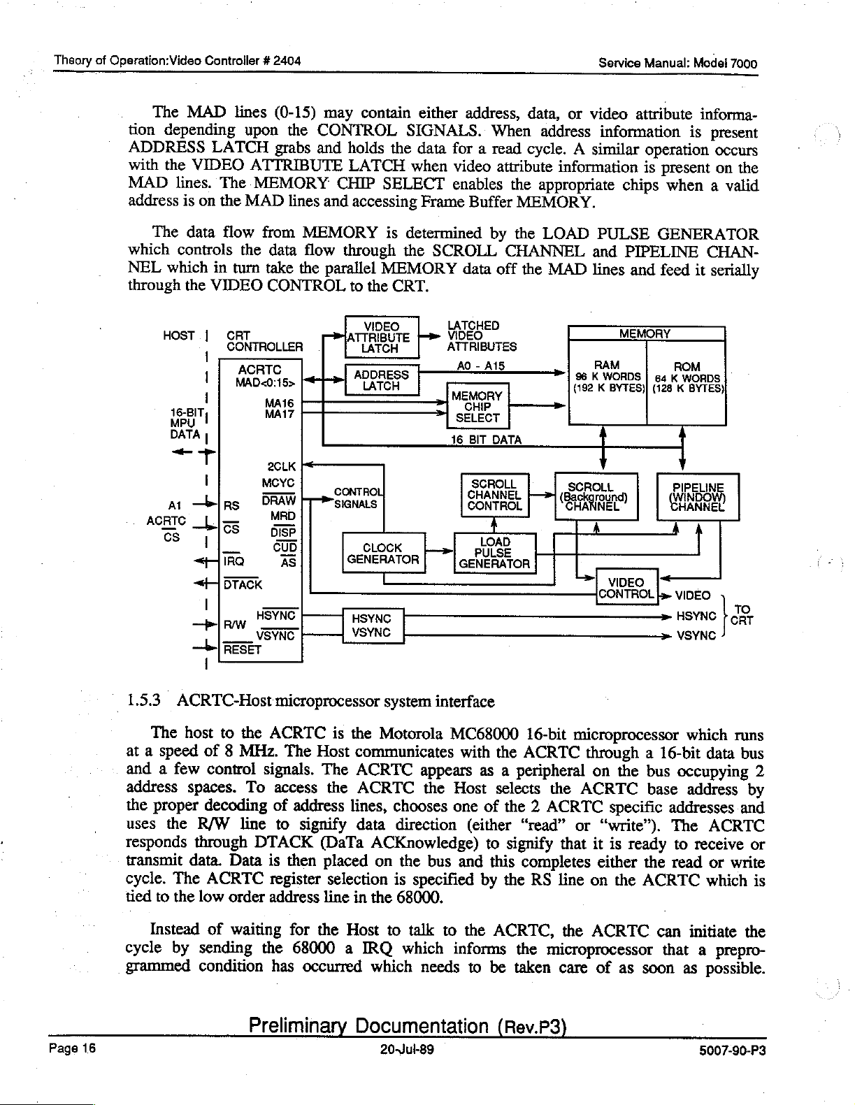
Theory
of
Operation:Video
The
tion
depending
ADDRESS
with
the
MAD
address
The
which
NEL
which
through
Controller
MAD
LATCH
VIDEO
lines.
The
is
on
the
data
flow
controls
in
the
VIDEO
#
2404
lines
(0-15)
upon
grabs
ATTRIBUTE
MEMORY
MAD
from
the
data
turn
take
CONTROL
the
CONTROL
and
lines
MEMORY
flow
the
may
contain
holds
LATCH
CHIP
and
accessing
through
parallel
to
the
either
SIGNALS.
the
data
when
SELECT
Frame
is
determined
the
SCROLL
MEMORY
CRT.
address,
When
for
a
read
video
enables
attribute
Buffer
by
data
off
data,
address
cycle.
the
appropriate
MEMORY.
the
LOAD
CHANNEL
the
MAD
Service
or
video
A
similar
information
attribute
information
chips
PULSE
and
PIPELINE
lines
and
Manual:
operation
is
Моде!
informa-
is
present
when
GENERATOR
CHAN-
feed
it
7000
present
occurs
on
the
a
valid
serially
HOST
ACRTC
cs
1.5.3
|
CRT
CONTROLLER
1
ACRTC
MAD<0:15>
1
18-BIT;
MPU
DATA
|
=
т
|
ar
—İrs
|
55
|
—
~<
IRQ
Pro
M
DTACK
—b | RESET
1
ACRTC-Host
>
ATTRIBUTE
MA16
MA17
2CLK
MCYC
二
DRAW
DER
e
CU
AS
HSYNG
VSYNC
CONTROL
SIGNALS
GENERATOR
HSYNC
VSYNC VSYNG
microprocessor
VIDEO
LATCH
ADDRESS
LATCH
CLOCK
LO.
system
He
interface
LATCHED
VIDEO
ATTRIBUTES
A0 - A15
MEMORY
CHP
|
SELECT
16
GENERATOR
->
BIT
DATA
SCROLL
CHANNEL
CONTROL
Å
LOAD
PULSE
+
RAM
|
96
K
(192
К
1
1
SCROLL
Back
MM
À
CONTROL
MEMORY
WORDS
BYTES)]
VIDEO
|
64
(128
|»
ROM
K
WORDS
К
BYTES)
Y
PIPELINE
WIN
HANNEL
A
VIDÉO
HSYNC
og
Page
16
The
host
at
a
speed
and
a
few
address
the
uses
spaces.
proper
the
responds
transmit
cycle.
tied
to
data.
The
the
Instead
cycle
by
grammed
to
the
of
8
MHz.
control
To
decoding
R/W
through
line
DTACK
Data
ACRTC
low
order
of
waiting
sending
condition
Preliminary
ACRTC
The
Host
signals.
The
access
of
address
to
signify
(DaTa
is
then
placed
register
address
the
has
line
for
the
68000
occurred
is
the
Motorola
communicates
ACRTC
the
ACRTC
lines,
data
chooses
direction
ACKnowledge)
on
the
selection
Host
a
in
IRQ
the
to
is
68000.
talk
which
which
Documentation
20-Jul-89
MC68000
with
appears
the
as
Host
one
of
(either
to
bus
and
specified
to
by
the
informs
needs
to
16-bit
the
ACRTC
a
peripheral
selects
the
the
2
ACRTC
“read”
signify
this
completes
the
RS
ACRTC,
the
microprocessor
be
taken
(Rev.P3)
microprocessor
through
on
ACRTC
the
a
bus
base
specific
or
“write”).
that
it
is
ready
line
the
care
either
on
ACRTC
of
the
as
the
ACRTC
soon
which
16-bit
data
occupying
address
addresses
The
ACRTC
to
receive
read
or
which
can
initiate
that
a
prepro-
as
possible.
5007-90-P3
runs
bus
2
by
and
or
write
is
the
Page 21
Service
Manual:
Model
7000
Theory
of
Operation:Video
Controller
#
2404
After
to
power
the
the
DACK
has
used
ate
the
ing
address
find
Also
proper
system
a
1.5.4
The
the
external
The
cycles.
receiving
16-bit
to
an
cause
the
out
on
the
microprocessor
is
first
applied,
initialization
gives
(Dma
The
CRT
assist
timing
Video
lines,
ACKnowledge)
data
bus
ACRTC-CRT
interface
the
and
hardware
Frame
Under
the
memory
MAD
Buffer
ding
on
Frame
address
IRQ
from
the
of
the
sequence
the
ACRTC
as
opposed
includes
ACRTC
control
provides
Buffer
its
control
and
MA
Address,
present
Buffer.
and
attribute
the
ACRTC
interrupt.
side
ACRTC
can
a
hardware
line
to
8-bit.
interface
the
in
controlling
signals
the
required
Memory
are
read
line
and
lines
Raster
state
Separate
provide
of the
status
of the
needs
take
reset.
which
needed
latches
is
signals
the
logic
is
managed
the
multiplexed
the
display
Address,
ACRTC
so
they
the
Host
ACRTC
to
be
placed
place.
When
tied
high
generated
CRT.
to
execute
between
either
or
in
the
remain
addresses
is
the
into
Pulling
The
by
drawing
Frame
Attribute
needed
hardware
the
to
tell
by
ACRTC
the
the
the
Drawing
address
valid
during
the
ACRTC
the
Host
line.
Buffer
for
the
ACRTC
reset
line
control
a
known,
RES
the
ACRTC
internal
system’s
ACRTC
and
information
manipulating
capture
the
predefined
line
is
reset
ACRTC
and
Processor
data
Data,
the
cycle.
Status
line.
low
on
power-up,
it
looks
that
the
and
the
hardware
processors
commands
the
CRT:
during
lines,
Frame
depen-
current
the
the
Register
When
state
so
at
the
system
gener-
while
draw-
raster
It
is
display
sors
and
The
grammed
MRD
between
cycles
displayed
of
DRAW
cycles,
play
the
cycles.
character/graphic
MAD
CUD
these
dow
generation
into
2CLK
All
(Memory
the
ACRTC
and
indicates
in
the
pipeline
video
the
works
and
with
with
periods.
responsibility
In
addition
signal.
and
MA
lines
1 & 2
signals
in
the
of
the
timing
is
timing
are the
to
superimposed
the
ACRTC
control
the
basic
events
ReaD)
superimposed
HSYNC
of the
to
the
line
and
the
whether
registers.
shift
MRD
to
Display
MAD
during
display
cursor
indicates
Frame
the
background
display
to
define
inhibit
Processor
and
MA
cycles.
generation
load
produce a blinking
mode.
timing
registers
ACRTC
can
be
signals
and
clock
traced
2CLK.
and
back
the
direction
Buffer
ACRTC
mode
pulse
to
lines
the
during
or
to
Frame
generation
manage
signals.
background
for
the
CRT
is
derived
to
this
clock
of
memory
window
enable
screens
load
Buffer
in
the
processor
The
area
also
system
under
depends
from
the
Dot
source.
data
flow
drawing
pulses
drawing
non-dis-
Frame
controls
uses
the
win-
on
the
Clock.
The
Dot
are
Buffer
the
values
during
cur-
pro-
5007-90-P3
Preliminary
Documentation
20-Jul-89
(Rev.P3)
-
Page
17
Page 22
Theory
of
Operation:Video
Controller
#
2404
Service
Manual:
Model
7000
Clock
is
and
MCYC
this
AS
has
Buffer
pulse
HSYNC
display
video
DRAW
2CLK
CRT
VSYNC
flicker
runs
at
used
to
latch
enable
is
(Address
been
load
is
manufactured
used
to
placed
address
generation.
is
the
line
beam
to
inhibit
to
latch
scan
line.
is
the
free
display.
20
pulses.
control
Strobe)
and
horizontal
and
to
the
vertical
DISP 1 & 2 are
video
signal
during
MHz
the
on
the
that
start
load
the
video
the
retrace
and
the
video
memory
provide
active
attributes,
by
signifies
MAD
sync
horizontal
of
the
pulses
attributes
sync
pulse.
video
periods.
2CLK
the
chip
lines.
qualification
pulse
during
runs
control
ACRTC
selects
that a valid
retrace
next
signals.
and
AS
is
to
indicate
should
line.
HSYNC
non-display
at
the
This
is
They
at 5 MHz.
memory
at
1/2
2CLK
enable
Frame
used
to
to
chip
the
occur
beginning
set
to
57
are
It
is
2CLK
chip
(2.5
load
pulses.
Buffer
latch
selects
end
of a current
to
is
also
periods
of
Hz
to
used
to
selects
MHz),
address
the
Frame
and
bring
used
and
each
present
blank
that
load
the
with
with
new
a
the
1.5.5
and
a
then
proper
address
used
is
1.5.6
MAD
held
pulse
1.5.7
ADDRESS
To
make
data
Frame
puts
memory
is
to
control
placed
VIDEO
The
Video
lines
for
for
MEMORY
share
Buffer
out
on
the
latches
When a Frame
be
selected
one
chip
supplying
uses
higher
EPROM
IC11A
regions,
and
efficient
the
access,
the
location
valid,
the
hardware
the
lines.
ATTRIBUTE
Attributes
carry
entire
IC4
(chips
order
IC9B
LATCH
use
of
MAD
the
data.
The
for
ACRTC
Inverter
available
signal
lines
ACRTC
address
the
data
provides
latches
IC24C
and
puts
must
transfer.
IC2
and
is
IC
a
used
LATCH
are
the
Attributes
raster
CHIP
and
line.
ICS
SELECT
Buffer
are
accessed
the
lower
address
with
each
saved
IC11C
which
access
lines
memory
in a similar
during
and
capture
is
requested,
in
pairs
8-bits
and
to
partition
chip
provide a validation
pins
are
put
out
the
be
To
signal
IC3
to
change
the
last
IC25D
the
Attributes
to
provide
the
other
the
pair
signal
the
video
on
address
held
signify
called
to
capture
way
2CLK
combine
one
attributes,
these
for
and
saved
the
the
and
the
polarity
as
explained
period
HSYNC
when
memory
lines
16-bits
the
upper
available
given a unique
by
gating
MCYC,
at
different
the
first
at
this
point
Address
hold
of
of
HSYNC
and
they
become
chip
pair
of
data
8-bits).
memory
2CLK,
Frame
half
of
point
in
the
Strobe
the
address
AS
for
in
section
2CLK
out
for the
The
space
base
starting
Buffer
times.
the
to
cycle
(AS)
while
IC’s
2
1.4.5.
and
need
to
valid.
of
several
ACRTC,
decoder
into
RAM
and
AS
address,
During
cycle
select
when
which
and
the
the
is
data
and
3.
The
to
be
produce
must
with
IC8A
and
address.
(a
chip
a
Page
18
Preliminary
Documentation
20-Jul-89
(Rev.P3)
5007-90-P3
Page 23
Service
Manual:
Mode!
7000
Theory
of
Operation:Video
Controller
#
2404
select
valid
IC14B
the
fers
data
nals
for
1.5.8
is
removal).
EPROMS
tionally
fonts
64 K words
words
1.5.9
pulse
address
and
memory
The
RAMs
data
from
into
the
the
circuitry
memory
MEMORY
The
Frame
volatile
The
are
removed
and
other
of
addressable
CLOCK
can
only
has
IC11D
at
the
proper
need
the
memory
RAM
creates
writes.
Buffer
(it
can
RAM
not
so
from
static
of
RAM
GENERATION
be
generated
been
placed
serve
to
time.
to
know
to
from
the
a
data
contains
be
read
space
volatile.
ACRTC
is
the
information
and
64 K words
on
clock
circuit
validated
if
the
the
ACRTC,
Drawing
direction
two
and
written
used
Data
which
memory.
if
the
the
MAD
ACRTC
Processor.
signal
types
of
to
as
video
placed
to
in
be
reprogrammed.
needs
of
EPROM
ACRTC
lines.
chip
select
is
executing
or
a
memory
By
which
memory:
repeatedly
memory
them
will
to
be
located
has
asserted
Gates
combining
to
used
IC24D,
pulses
a
memory
write
is
high
RAM
but
hold
not
be
The
over and
in
from
and
looses
dynamic
the
AS),
the
read
cycle
the
MRD
for
memory
EPROM.
lost
unless
EPROMS
first
signifying
E,
F;
address
cycle
which
and
its
data
screen
the
are
over
again.
half
of
that
IC13A,
decoder
which
will
place
DRAW
reads
RAM
and low
memory
with
displays.
chip
is
used
to
There
the 2 Mega-
a
B,
C;
to
trans-
new
sig-
power
The
inten-
hold
are
The
entire
ing
pulse
by 4 through
1.5.10
Data
carefully
latch
of
information
ground
with
arrive
IC9B
controls
2CLK,
every
To
monitors
nals
superimpose
es
or
derived
IC10
LOAD
retrieved
coordinated
the
data
and
window
the
MCYC
at
the
video
uses
AS
timing
MCYC
eighth
dot
inhibit
both
are
active.
window
IC14C
superimposed
video
mode
attribute
to
the
Video
ACRTC
directly
to
PULSE
from
from
the
is
sent
periods
shift
and
MCYC
pulses
and
clock
load
DRAW
The
for
load
mode.
to
channel
Pipeline.
circuitry
from
produce
the 5 MHz
GENERATOR
the
Frame
manner.
video
to
the
screens,
of
registers
to
(generated
another
into
pulses
and
timing
gates
during
HSYNC,
last
are
produced
pulses
Gates
IC25C,
regular
runs
synchronously
the
Dot
Buffer
The
load
memory
display.
two
the
signify
To
sets
ACRTC.
at
the
that
by
IC15C)
pulse
IC14 A and
cycles
turning
signal,
MRD
by
which
IC16B
loads
Clock
at
of
oscillator.
2CLK
pulse
signal.
for
display
circuitry
the
precise
set
the
load
These
proper
a
valid
display
pulses
pulses
time
address
through
generated
C.
reserved
gates
IC14A
determines
selectively
trail
the
turning
regular
and C and
for
interleaved
off
the
2CLK
The
needs
generates
moment
up
must
need
and
in
has
gate
by
IC10
for
non-display
and C off
if
on
loads
IC6C
or
which
20
MHz
to
be
sent
the
so
that
for
superimposing
be
generated
to
be
the
correct
been
placed
IC6B.
Then
to
produce
offset
IC14A
by 8 dot
work
offset
with
loads
is
the
Dot
Clock
out
to
the
control
a
signals
continuous
which
channelled
sequence.
on
IC15C
one
periods,
when
load
for
those
pulses
regular
clocks
MODE_SELECT
for
superimposed
master
is
divided
CRT
which
stream
the
back-
tim-
coincide
so
they
Flip-flop
the
bus
combines
load
pulse
gates
IC6D
two
for
load
puls-
in
in
a
and
sig-
the
the
5007-90-P3
Preliminary
Documentation
20-Jul-89
(Rev.P3)
Page
19
Page 24
Theory
of
Operation:
Video
Controller
#
2404
Service
Manual:
Model
7000
1.5.11
convert
channels,
zontal
(Video
offset
buffer
lowing
first)
IC31
pair
1C27.are
HDS0-3
possible
multiplexers
shift
position
the
the
putted
position.
address, a new
ly
SCROLL
The
video
it
pixel
Pipeline)
load
The
scroll
data
dot
and
and
are
The
current
register
from
HDS
shift
to
across
into
one
scrolling
pulses
into
clock,
shifts
IC32.
full
and
filled
lines
16
will
IC33
display
lines
register
the
The
the
screen.
CHANNEL
shift
registers
a
serial
used
for
which
to
latch
channel
the
first
the
down
After
the
with
the
background
at
the
begin
and
video
above
video
9
and
indicated
output
mixers,
bits
below
starting
stream
the
(Scroll
does
the
uses
pair
frame
one
16
dot
first
next
start
of
that
IC34
fed
that
line
bit
&
PIPELINE
take
parallel
of
information
background
Channel)
not
support
video
data
regular
of
scroll
buffer
bit
at
a
clocks,
pair
are
Data
word.
screen’s
each
raster
current
to
will
into
for
and
bit
position
display
determine
be
taken
Video
the
display
that
on
10
are
frame
screens
and
off
load
pulses
channel
data
time
into
16
shifts
empty.
start
scan
from.
Mixer
bit
would
each
new
ignored
is
selected
CHANNEL
buffer
for
which
one
smooth
of
the
data
shift
leaves
the
have
A
new
dot
address
line
line.
which
New
IC17A
should
be
dot
and
and
display
the
CRT.
is
is
used
scrolling
bus.
which
registers
the
output
second
taken
load
to
determine
The
HDS
data
There
designated
for
but
it
uses
IC26
of
scroll
place,
pulse
is
is
placed
lines
corresponding
data
is
continually
via
the
multiplexers.
start
with
the
selected
clock
not
the
by
the
next
displayed.
display
off
of
are
two
to
allow
the
superimposed
can
use
to
parallel
and
IC27.
IC26
(least
channel
the
second
generated
on
the
which
control
output
10th
the
By
appears
one
line
shifted
bit
multiplexers
bit
would
updating
the
data
separate
smooth
either
shift
gates
of
regular
load
the
On
significant
register
shift
and
IC26
video
bit
out
IC25E,
of
the
into
For
example,
the
data
to
be
fed
the
to
move
bus
and
video
hori-
window
or
frame
each
fol-
bit
pair
register
and
attribute
of
the
and
second
this
bit
if
word,
be
out-
to
this
start
dot
smooth-
The
video
scrolling,
the
window
there
is
separate
or
window
1.5.12
active
data
sent
and
active
play
attribute.
VIDEO
The
video
streams
to
the
2
signals
video
format
pipeline
non-superimposed
during
control
or
both
can
its
cycle
in
screens.
CONTROL
video
output
period.
sending
CRT
depends
from
cycle.
or
inverse
sends
Video
the
the
ACRTC
Gates
IC16A
video
either
display
in
the
any
display
the
mixer
result
on
the
black
be
loaded
of
video
superimposed
mode
serialized
IC17A
into
gate
control
and
and
signal
inhibits
IC12C
on
white
with
data,
to
selectively
display
combines
IC7A.
from
the
video
select
is
regular
or
with
offset
display
the
mode.
information
video
Whether
IC12D
output
whether
chosen,
this
load
pulses
load
For
enable
to
pipeline
the
mixed
which
if
the
a
regular
is
to
provide
pulses
each
or
disable
the
and
for
video
background
CRT
scroll
video
monitors
system
white
controlled
the
is
on
by a video
non-
latching
channel
during
channel
signal
DISP
not
in
black
the
gets
1
the
dis-
Paga
20
Preliminary
Documentation
20-Jul-89
(Rev.P3)
5007-90-P3
Page 25
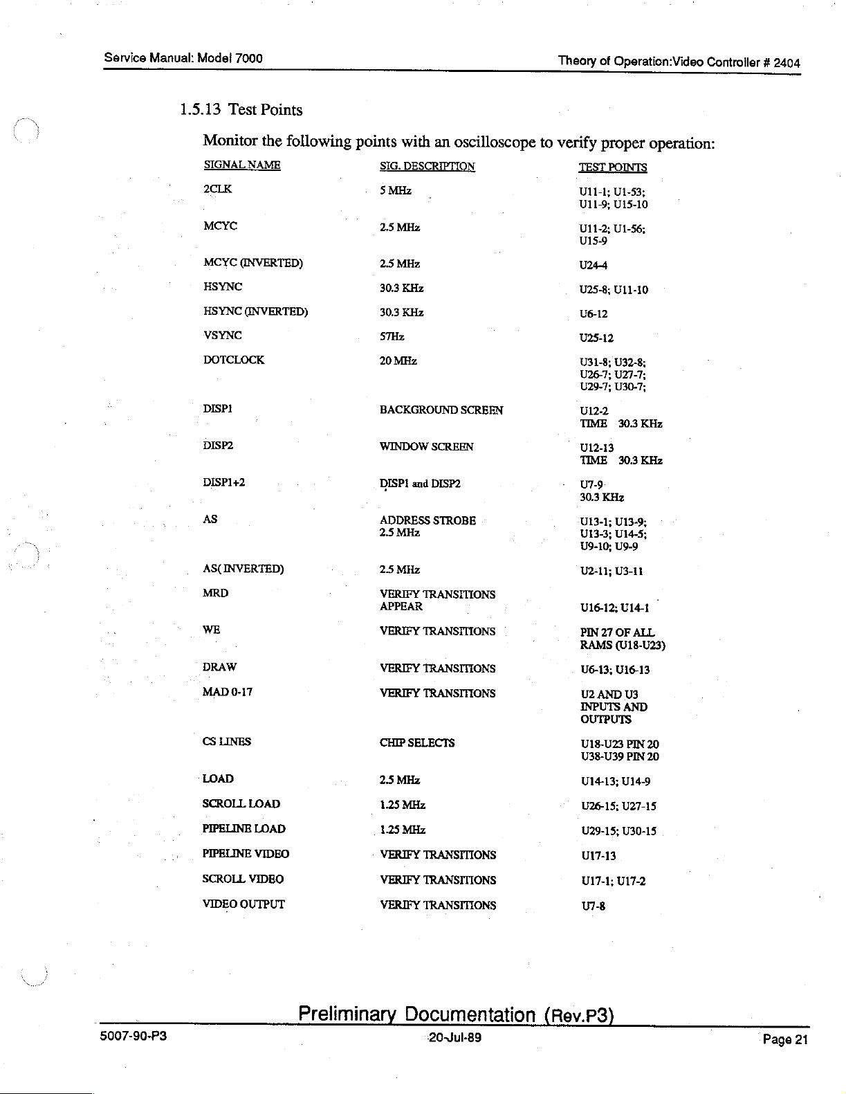
Service
Manual:
Model
7000
Theory
of
Operation:Video
Controller
#
2404
1.5.13
Test
Monitor
SIGNAL
2CLK
MCYC
MCYC
HSYNC
HSYNC
VSYNC
DOTCLOCK
DISPI
DISP2
DISP1+2
AS
ASCINVERTED)
MRD
WE
DRAW
MAD
CS
LINES
LOAD
SCROLL
PIPELINE
PIPELINE
SCROLL
VIDEO
Points
the
NAME
(INVERTED)
(INVERTED)
0-17
LOAD
LOAD
VIDEO
VIDEO
OUTPUT
following
points
with
SIG.
DESCRIPTION
5
MHz
2.5
MHz
2.5
MHz
30.3
KHz
30.3
KHz
37Hz
20
MHz
BACKGROUND
WINDOW
DISPI
and
ADDRESS
2.5
MHz
2.5
MHz
VERIFY
APPEAR
VERIFY
VERIFY
VERIFY
CHIP
SELECTS
2.5
MHz
1.25
MHz
1.25
MHz
VERIFY
VERIFY
VERIFY
an
oscilloscope
SCREEN
SCREEN
DISP2
STROBE
TRANSITIONS
TRANSITIONS
TRANSITIONS
TRANSITIONS
TRANSITIONS
TRANSITIONS
TRANSITIONS
to
verify
proper
TEST
POINTS
Ul1-1;
Ul-53;
U11-9;
U15-10
U11-2;
U1-56;
U15-9
U244
U25-8;
U11-10
U6-12
U25-12
U31-8;
U32-8;
U26-7; U27-7;
U29-7; U30-7;
U12-2
TIME
30.3
U12-13
TIME
303
U7-9
30.3
KHz
U13-1; U13-9;
U13-3; U14-5;
U9-10;
U9-9
U2-11;
U3-11
U16-12;
U14-1
PIN
27
OF
(018-023)
U16-13
AND
U14-9
U27-15
U30-15
U17-2
ALL
U3
AND
PIN
PIN
RAMS
U6-13;
U2
INPUTS
OUTPUTS
U18-U23
U38-U39
U14-13;
U26-15;
U29-15;
U17-13
U17-1;
U7-8
operation:
KHz
KHz
20
20
5007-90-P3
Preliminary
Documentation
20-Jul-89
(Rev.P3)
Page
21
Page 26
Theory
of
Operation:CO2
Front
End # 2418, # 2421
Service
Manual:
Model
7000
1.6
CO:
Front
1.6.1
the
microcomputer.
end
ed
boards
serial
red
1.6.2
as
by
1
state of
bits
“Expanded
Introduction
The
interface
board
through
link
CO»
Mode 1 Operation
The
well
the
Hitachi
which
After
when
End # 2418
capnometer
between
and
connector
provide
as
well
sensor.
digital
as
the
functions
the
microcontroller
three
pins;
the
Non-multiplexed
interface
It
is
made
the
2418
P3
continuous
as
providing
DIGITAL
front
end
control
HD63701
reset
and
as
follows:
P20, P21,
goes
(2409), # 2421
system
the
infra-red
up
of
(previously 2409)
and
are
real
FRONT
board
timing
microcontroller.
is
reset,
and
high.
Mode”.
designed
COz
two
(2)
connected
time
CO2
all
the
necessary
END
provides
of
the
the
P22.
This
sets
(2407)
by
Cascadia
Sensor
boards;
analog
to
reading
BOARD
the
interface
analog
This
microcontroller
configuration
These
the
microcontroller
(Capnostat™
the
piggyback
external
to
control
#2421
interface
pins
are
Technologies
2421
(previously
board.
circuitry
the
host
signals
(previously
to
the
host
to
the
is
of
the
device
latched
to
Corporation
Sensor)
They
through
microcomputer
to
the
and
2407)
are
interconnect-
P208.
Capnostat™
2407)
microprocessor
CO2
Sensor.
set
up
is
into
the
Mode 1 which
It
to
operate
determined
program
the
digital
front
These
through
infra-
system
is
operated
in
Mode
by
control
is
called
is
host
two
a
the
In
Mode
P10-P17)
address
Finally,
port.
which
opens.
tions
transmit
1.6.3
by 4 to
by
down
(Auto
trol
1.6.4
ate
Motorola
lines
port 2 (P20-P24)
P22
monitors
Pin
to
the
data)
System
The
crystal
provide
512
to
further
Zero)
acquisition
Mode
In
order
in
mode 1 on
1,
port 3 (pins
functions
as
A8-A15.
is
configured
XDUCER
P20
is
configured
host
processor.
of
the
serial
clocks
frequency
the
system
establish
(on
and
the
piggyback
S/H
of
CO2
configuration
to
correctly
power
MC14053
analog
P30-P37)
address
Pin
SC1
is
configured
as a 4800
DISC, a signal
as
Pins
link.
input
clock
4800
(Sample
data.
support
write
up,
multiplexer/demultiplexer
lines
on
Hz
DTR
P23
to
the
output
Hz
clock
board
and
hardware
to
pins
and
functions
A0-A7,
port 3 is
unused
as a combination
clock
output,
which
which
is a handshaking
and
P24
are
HD63701
on
the
E pin
out
on
which
Hold)
P20-P22
then
will
signals
on
switch
as
the
data
and
port 4 (P40-P47)
and
pin
I/O
P21
is
configured
is
generated
the
RXD
is
2.4576
MHz,
of the
P22.
This
4800
be
explained
which
the
pins
are
the
HD63701
P20-P22
(IC1)
bus
bits
DO-D7,
SC2
acts
and
serial
as a TTL
when
line of the
and
TXD
this
frequency
HD63701
Hz
is
later)
two
so
is
main
it
is
to
I/O
used.
to
port 1 (pins
is
configured
as a R/W
communications
level
the
CO2
serial
and
configured
On
communica-
(receive
ultimately
generate
pulses
is
data
is
also
that
divided
divided
divided
the
to
function
system
lines,
reset
as
signal.
input
sensor
and
AZ
con-
oper-
a
an
Page
22
Preliminary
Documentation
20-Jul-89
(Rev.P3)
5007-90-P3
Page 27

Service
Manual:
Model
7000
Theory
of
Operation:CO2
Front
End
#
2418,
#
2421
output
zero.
ly)
On
register
established,
pins
is
the
1.6.5
the E
is
low)
1.6.6
This
memory
from
This
internally
to
the
X,
the
rising
and
on
IC1
DTRI,
I/O
Additional
R/W.
XDUCER
lines).
RD
and
pin
on
The
signals.
Decoding
Decoding
is
done
map
octal
a
to
D-type
Y,
and Z pins
edge
establishes
write
a
high
WR
microprocessor
the
HD63701
74HC00
on
board
by
feeding
output
HEX
0000-1FFF
2000-3FFF
4000-5ΕΕΕ
6000-7FFF
8000-9FFF
flip
switches
of
the
the
to
octal
state.
DISC,
signals
(IC17)
is
a
A13-A15
is
as
follows:
ADDRESS
A000-BFFF
C000-DFFF
E000-FFFF
flop
the
of
IC1,
reset
pulse
processor
flip
flop
This
switches
and
4800
control
with
along
memory
H
H
Η
H
H
H
H
H
IC3
logic
which
SC2.
with
map
into
is
cleared
levels
the
[C3
Hz
signals
The E pin
IC4
on
are
connected
001
mode
is
done
pins
clock
RD
SC2
and E generate
which
(74HC138)
which
XO,
levels
(mode
by
X,
Y,
are
now
and
acts
consists
CHIP
Unused
Unused
Unused
IC3
chip
IC9
chip
ICS
chip
1C31
1C6
chip
forces
YO,
and
to
pins
are
loaded
1).
Once
software
and
Z
to
connected
WR
are
as
the
of
which
SELECT
select
select
select
chip
select
select
the
A,
ZO
P20-P22
into
which
X1,
further
system
the
RD
8
blocks
is
a
SIGNAL
(octal
(AGC
(quad
(RAM)
(EPROM)
B, C inputs
inputs
the
Y1,
to
3
(001
on
the
program
processor
sets
the
and
Z1
P20-P22
generated
clock
to
FF)
output
and
WR
of
8
8
line
latch)
Kilobytes
A/D)
(not
of
IC1
respective-
the
HD63701.
control
mode
A,
B,
and
on
ICI,
(they
by
gating
and
(both
」
decoder.
used)
to
is
C
that
act
as
SC2
active
each.
The
©
5007-90-Ρ3
1.6.7
HM6264
bytes
PROM
1.68
Memory
On
board
of
found
Octal
The
(8K X 8)
RAM
octal
mentioned
outputs
of
The
outputs
+
Output
microcontroller
memory
which
internal
flip
flip
the
CLR
IC3
to
of
O1
includes
(this
is a spare
is
internal
to
the
HD63701
flop
IC3
flop
IC3
(74HC273)
input
be
cleared
the
controls
flip
flop
(IC2)
pin
to 0 on
the
to
Preliminary
EPROM
to
IC6
allocation
the
HD63701
which
is
used
on
IC3
is
connected
each
reset
are
labelled
switching
mode 1 as
Q1-Q8
of
described
Documentation
20-Jul-89
which
is a HN27C64
on
the
board,
microcontroller.
are
not
used
when
to
generate a variety
to
the
of the
and
ICI
system.
function
which
earlier.
(Rev.P3)
reset
is
used
|
(8K X 8),
it
is
not
currently
There
in
Mode 1 operation.
system.
as
follows:
to
is 4 K
of
signals.
This
set
the
RAM
IC31
used),
bytes
As
already
causes
HD63701
Page
a
128
of
the
23
Page 28

Theory
of
Operation:CO2
Front
+
Output
signal
the
receive
+
Output
End
#
2418,
Q2
is a signal
used
in
host
microprocessor
serially
Q3
is
presently
#
2421
called
the serial
transmitted
communication
that the
unused.
DSR1
data.
(Data
interface
Set
link
Ready
to
the
system
Service
1),
this
host
microprocessor.
microcontroller
Manual:
is a
handshaking
is
Model
It
tells
ready
7000
to
Output
for
only
software
trols
time
+
Output
sistor
boost
*
Output
tem
tional
*
Outputs
1.6.9
A/D
converter
results
microcontroller.
A/D
The
AD7582KN
converter.
are
Q4
controlling
if
jumper
can
the
maintenance
this
option
Q5
Q1
heater
Q6
is
running
after
Q7
converter
Each
with
a
read
is
the
HEATER
the
W1
override
is
not
is
called
which
power-up.
conversion
in
is
on
or
off.
is
connected
and
and
Q8
(ICS)
input
2
bytes,
CONTROL
maintenance
is
installed
the
servo-control
heaters
used.
HEATER
an
IRF523
to
LED
is
used
as a method
are
spare
outputs
is
a
four
input
channel
8
time
LSBs
has
of
1,
it
heaters
on
the
by
shutting
CONTROL
power
CR2,
channel
an
output
approximately
and
analog
thermistor
MOSFET.
which
and
are
4
MSBs.
in
of
range
is a software
the
CO2
piggyback
amplifier
down
2,
successive
transistor
this
output
This
flashes
determining
not
used.
of
0-5
100
usec
Either
byte
heater
sensor.
board.
directly
MOSFET
when
if
approximation
VDC.
per
can
control
It
is
With
circuit
Q2.
At
the
Cascadia
the
system
It
is
channel.
be
operational
this
which
the
controls
switches
a
read
option
option,
con-
present
tran-
sys-
is
func-
12
bit
medium
Conversion
first
the
CMOS
speed
by
the
Page
24
The
four
analog
TEMPCHI,
LF398
of
the
nance
heaters
represents
is
in
series
the
resistor,
1.6.10
AGC
The
74HC273
and
sample
and
thermistor
in
the
voltage
with
the
circuit
AGC
(Automatic
(C9)
plexers/demultiplexers.
ground.
During
which
nected
and
The
calibration
resistors
through
set
the
gains
resistors
channels
CURRENT.
hold
amplifier
the
CO2
drop
the
infra-red
current
is
an
to
octal
are
of
the
are
internally
to
lines
on
the
IC28
circuits
the
Gain
On
slightly
sensor
DGAIN
Preliminary
which
DATACH
circuit
sensor
across
source
source
flip
flop
each
are
on
the
which
as
a
resistor
in
can
Control)
and
of
the
different
(after
selected
and
RGAIN
OPAMP
circuits
Documentation
20-Jul-89
input
analog
mentioned
and
is
the
to
REFCH
piggyback
(R60)
the
CO2
be
monitored
circuit
IC13
16
is
and
outputs
in
value,
warm-up)
by
IC13
and
which
of
the
the
converter
are
board.
servo-controlling
earlier.
on
sensor.
made
IC14
on
the
By
to
protect
up
are
IC13
CURRENT
piggyback
ranging
the
octal
flip
IC14.
The
connect
DATA
and
are
the
direct
TEMPCHI
circuit
monitoring
against
of
IC9,
CD4067
and
IC14
from
flop
IC9
selected
over
to
REF
channels.
(Rev.P3)
DATACH,
outputs
for
is
an
board.
the
REFCH,
from
is
the
the
input
This
voltage
malfunctions.
IC13,
CMOS
1.96
and
analog
is
a
1%
Ka
is
used
resistors
the
piggyback
IC14.
resistor
to
12.1
to
are
5007-90-P3
the
output
mainte-
which
resistor
across
The
multi-
to
Ko.
control
con-
board
Page 29
Service
Manual: Model
7000
Theory
of
Operation:CO2
Front
End
#
2418,
#
2421
1.6.11
the
On
and
CO?
1.6.12
heater
1,
for
gate
directly
PCHI
circuitry
TEMPCHI
Voltage
VREF
analog
the
digital
is
fed
sensor.
Main
The
MAIN
and
2,
and
safe
sensor
*
by
*
if
In
either
voltage
In
addition
to
to a 6.7
HEATER
reference
is a +5 V signal
piggyback
front
to
IC19,
Further
heater
board.
end
an
emitter
uses
on
control
HEATER
maintenance
3,
transistor
use.
unplugging
the
thermistor
case
the
to
Q19.
to
this,
IC30
pin
VDC
malfunction
to
exceed
CONTROL
Q19,
For
example,
the
XDUCER
This
2.
This
level
and
line
heaters
in
cuts
the
6.7
which
VREF
board
it
follower
the
analog
circuit
CONTROL
in
and
Q20.
the
sensor,
the
CO2
DISC
off
power
output
circuit
provided
cause
volts
by
shutting
is
used
throughout
is
generated
serves
(only
the
XDUCER
sensor
from
as
the
circuit
piggyback
on
line
CO2
Different
should
signal
to
the
to
2421
boards)
provides
sensor.
DISC
is
the
maintenance
thermistor
is a comparator
by
the
resistor
thermal
and
power
off
Q19.
runaway,
both
the
by a precision
reference
generate
board
the
It
safety
signal
open.
fed
directly
circuit
divider
the
is
again
voltage
VB, a bias
will
be
required
includes
features
can
to
heater
amplifier
which
of
overheating
disconnected
digital
explained
are
be
Q20
compares
R140
front
voltage
for the
power
the
circuitry
built
generated 2 ways:
control
circuit
reference
voltage
later.
for
into
which
output.
TEMPCHI
the
and
R141.
of
the
from
end
board
A/D
converter,
used
both
of
IC30
this
shuts
output
Should
sensor
the
and
(IC8).
in
the
the
boost
pins
circuitry
down
is
the
fed
TEM-
any
causes
MAIN
1.6.13
tion
and
give a brief
of
way
spectrum
absorption.
within
outside
level
compared
Introduction
The
analog
from
the
detectors
overall
As
the
CQ2
48
Hz.
The
and
then
of
Behind
the
CO2
the
CO2
To
acquire a precise
of
CO?
to a lookup
ANALOG
piggyback
CO2
sensor.
is
done
explanation
passes
infra-red
passes
CO2
absorption
each
absorption
absorption
is
determined
table
PIGGYBACK
board
All
through
through
energy
through
and one outside
light
filter
range
range
level
from
in
memory
provides
required
this
circuitry.
of
how
the
the
airway
from
the
two
light
is
is
for
is
for the
of
CO2,
the
ratio
to
BOARD
the
required
power
COz
and
Before
data
adaptor,
source
filters,
an
infra-red
the
data
reference
both
channels
of the
establish
#2418
biasing
going
is
acquired.
an
is
absorbed
one
filter
the
infra-red
detector.
channel
channel.
are
data
the
correct
(previously
interface
voltages
into
infra-red
partially
within
frequency
The
and
the
sampled
and
reference
value
2409)
circuitry
the
source
the
for
data
to
the
infra-red
circuitry,
is
pulsed
by
the
CO2
infra-red
spectrum
detector
detector
behind
behind
simultaneously
channels.
in
units
of
mmHg.
acquisi-
source
it
is
best
at a rate
in
the
frequency
of
CO
the
filter
the
filter
and
The
ratio
to
air-
the
is
5007-90-P3
Preliminary
Documentation
20-Jul-89
(Rev.P3)
Page
25
Page 30
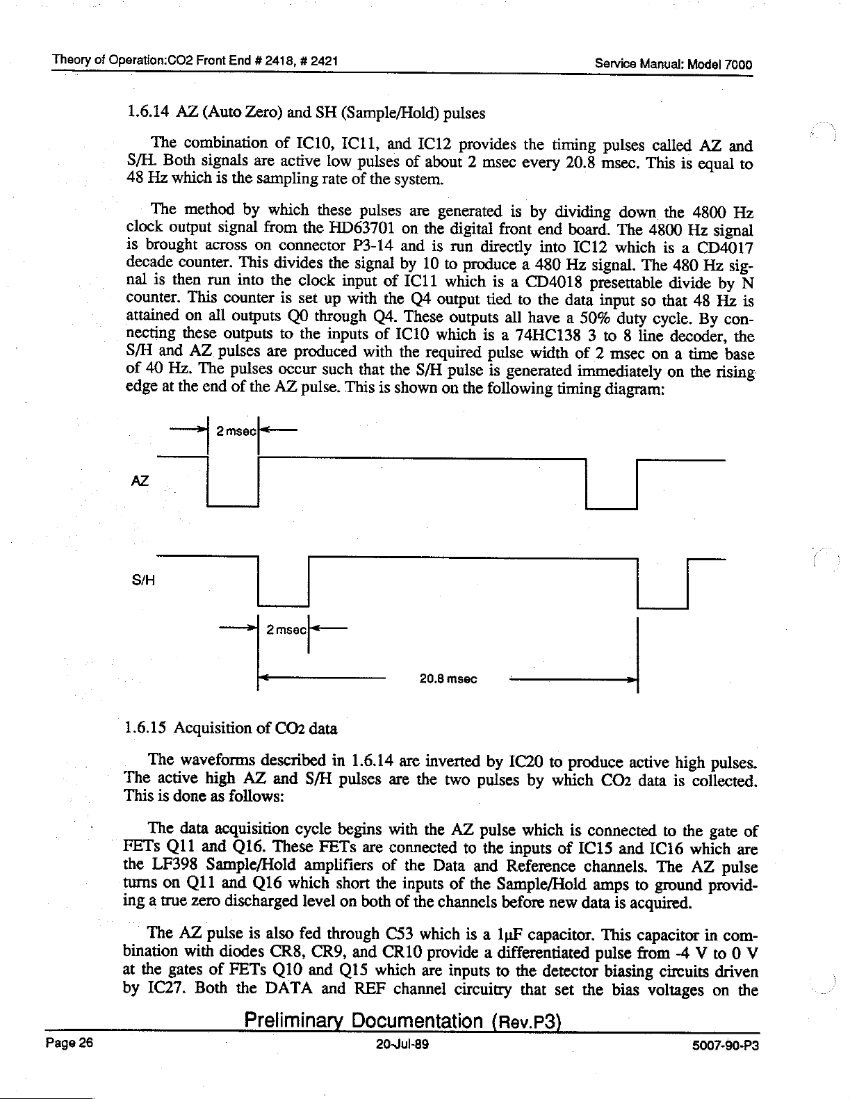
Theory
of
Operation:CO2
Front
End
#
2418,
#2421
Service
Manual:
Model
7000
1.6.14
S/H.
48
clock
is
decade
nal
counter.
attained
necting
S/H
of
edge
AZ
The
Both
which
Hz
The
output
brought
counter.
is
then
these
and
40
Hz.
at
the
(Auto
combination
signals
method
This
on
AZ
The
end
Zero)
the
is
by
signal
across
This
run
into
counter
all
outputs
outputs
pulses
pulses
of
2msec
are
sampling
from
on
the
and
SH
of
IC10, IC11,
active
which
divides
the
are
AZ
these
the
connector
clock
is
set
QO
through
to
the
produced
occur
pulse.
(Sample/Hold)
and
low
pulses
system.
the
of
rate
pulses
HD63701
P3-14
the
signal
input
of
up
with
the
O4.
inputs
such
with
that
This
of
the
is
IC10
shown
IC12
of
about
are
on
the
and
by
10
IC11
Q4
These
the
required
S/H
pulses
provides
2
msec
generated
digital
is
run
directly
to
produce
which
output
which
on
tied
outputs
is
pulse
pulse
is
the
following
the
every
is
by
front
end
into
a
480
is
a
CD4018
to
the
all
have
a
74HC138
width
generated
timing
dividing
timing
pulses
20.8
msec.
board.
IC12
Hz
signal.
presettable
data
input
a
50%
3
to
of
2
immediately
diagram:
down
The
which
duty
8
line
msec
called
This
the
4800
is
The
480
divide
so
that
cycle.
decoder,
on
a
on
AZ
is
equal
4800
Hz
a
CD4017
Hz
48
By
time
the
and
to
Hz
signal
sig-
by
N
Hz
is
con-
the
base
rising
S/H
1.6.15
The
This
FETs
the
turns
ing
bination
at
by
Acquisition
The
waveforms
active
is
done
The
data
Q11
LF398
on
O11
a
true
The
AZ
with
the
gates
IC27.
(e_
of
described
high
AZ
as
follows:
acquisition
and
Q16.
Sample/Hold
and
O16
zero
discharged
pulse
is
diodes
of
FETs
Both
the
DATA
2msec
CO2
and
S/H
cycle
These
amplifiers
which
level
also
fed
CR8,
Q10
and
data
in
pulses
begins
FETs
short
on
through
CR9,
O15
and
—
1.6.14
are
are
with
are
connected
of
the
both
of
C53
and
CR10
which
REF
channel
20.8
inverted
the
the
the
Data
inputs
the
channels
which
provide
are
msec
by
two
pulses
AZ
pulse
to
the
and
Reference
of
the
Sample/Hold
before
is
a
lpF
a
differentiated
inputs
to
circuitry
AAA
IC20
to
produce
by
which
which
inputs
is
of
new
capacitor.
the
detector
that
set
|
active
CO2
data
connected
IC15
and
channels.
amps
data
is
acquired.
This
pulse
to
capacitor
from
biasing
the
bias
high
is
collected.
to
the
gate
IC16
which
The
AZ
ground
circuits
voltages
-4
provid-
in
V
pulses.
of
are
pulse
com-
to
0
V
driven
on
the
Page
26
Preliminary
Documentation
20-Jul-89
(Rev.P3)
5007-90-P3
Page 31
Service
Manual:
Model
7000
Theory
of
Operation:CO2
Front
End
#
2418,
#
2421
detectors
cussed
During
point
for
channel)
rent
transistor
through
of
Q7
properly
should
Immediately
out
acguisition.
The S/H
cuit.
lockup
occur,
would
to
that
the
DATA
level
and
be
of
IC10.
This
with
IC29
be
are
avoid
the
Q10
have
of
circuitry
a
10
Q8.
set
zero
circuit
disabled
identical.
redundancy.
AZ
pulse,
and
Q15
and
REF
a
high
DATAOUT
of
KQ
resistor
VBDATA
should
It
signal
the
pin
be
volts.
following
is
connected
is
is
to
S/H
7
would
which
For
no
are
channels.
time
is
Q7,
Q8,
(R70)
in
the
the
routed
protect
pulse
go
in
turn
the
most
SOURCE
turned
constant
fed
through
and
Q9.
and
is
the
bias
-30
to
AZ
pulse
to
a
variety
to
IC29
the
actively
to
a
low
would
part,
only
pulse
on
and
zero
The
RC
combination
of
approximately
Q10
Transistor
along
pin
infra-red
driving
with
voltage
-40
VDC
is
the
of
circuits
2.
This
the
state
and
disable
the
is
driving
source
on
the
Q7
output
for
the
range.
S/H
pulse.
which
is
the
source
infra-red
the
the
source
DATA
the
bias
of
0.26
AZ
pulse
acts
as
of
IC27
DATA
It
is
This
control
input
from
overheating
source.
initial
drive
channel
infra-red
level
is
C50
and
seconds.
and
this
a
current
controls
channel
at
this
point
pulse
the
to
a
pulse
If
source
drive
circuitry.
circuitry
source.
set
on
the
R72
(on
The
zero
in
turn
source
the
biasing
detector
that
is
active
actual
this
CO2
width
watchdog
due
to
situation
switch
will
be
It
is
at
detectors
the
DATA
source
biases
from
+15
point
and
when
DATAOUT
low
coming
data
a
circuitry
were
output
dis-
this
cur-
the
V
level
cir-
to
Q6
The
S/H
Q6
on
and
off
pulse
pin
a
is
is
drop
inverting
inverting
R63.
The
passed
being
el.
seen
end
inverted
the
controller.
Finally,
and
is
first
7
is
a
are
tied
from
pulse
from
a
non-inverting
The
source
sent
directly
in
order
amplifier
summing
This
other
through
driven
When
on
IC26-7.
board
Besides
through
digital
the
IC16
to
signal
gives
input
the
and
being
front
This
active
control
pulse
is
to
provide
run
through
of
2.5
this
output
+0.57
V
amplifier
drive
off
board
to
measure
U26-1,2,
amplifier
a
total
of
the
one
through
source
This
is
fed
the
IC20
end
signals
high
the
differentiated
the
initial
the
emitter
V
with
an
to
-15
V.
to
-1.66
V
on
with
a
gain
signal
to
the
at
this
the
and
source
source
3
IC26
gain
of
10
the
summing
ohm
resistor
the
source
is
being
current
into
the
pulse
to
provide
board
the
S/H
sampling
(IC25-3
driven
output
A/D
converter
which
and
is
controller
pulse
of the
through
stage
follower
active
These
the
point
of
low
resistors
high
of
9,
is
run
on
P3-7.
C38
pulse
impedance
providing
current.
which
pins
(-0.5
amplifier
5,
x
R60.
=
has
6,
and
-20)
is
It
has
-15
(IC25-3=+5V),
goes
directly
ICS.
generates
an
active
connected
is
connected
to
high
to
start
DATAOUT
and
then
the
source
circuit
a
IC24
to
0
form
the
through
The
resistor
To
do
gain
of
7
with
through
connected
a
gain
V),
the
the
off
the
source
pulse.
the
NMI
the
CO2
to
pin 8 of
and
drives
drive
pins
V.
The
a
voltage
input
source
a
one
R60
this,
the
-0.5
a
gain
this
side
to
the
of
-10.
output
slight
board
current
This
pulse
input
data
acquisition
the
REFOUT
the
gate
timing
5,
two
of
drive
ohm
pulse
6,
and
resistors
divider
IC25.
of
resistor
The
-15
provides
output
V.
Output
of
of
-20
the
IC25-3
through
summing
source
When
U26-7
voltage
on
P3-9
there
has
drop
to
drive,
is
fed
pin
of
the
sample/hold
channels.
of
Q6.
This
circuitry.
7.
On
the
R54
which
circuit
V
to
+5
(R60)
a
small
is
U26-1
is
the
amplifier.
drive
a
zero
after
is
no
across
the
digital
the
S/H
through
HD63701
software
amplifier
turns
This.
output
and
R55
provides
of
IC25
V.
and
then
voltage
fed
into
fed
into
input
of
it
has
current
volt
lev-
R60
is
front
pulse
P3-18
is
to
micro-
routines.
IC15
5007-90-P3
Preliminary
Documentation
20-Jul-89
(Rev.P3)
Page
27
Page 32

Theory
of
Operation:CO2
Front
End
#
2418,
#
2421
Service
Manual:
Model
7000
1.6.16
reaches
This
IC25
drive
latch
vent
from
IC10
XDUCER
ducer
1.6.17
detectors.
and
switches
input
1N4938
fied
regulator
transformer
Additional
ICX1
Transistor
Transistor
The
Transistor
As
is a MAX8211
4.75
is
found
pin
4.
circuit
of the
any
harmful
combination
random
to
be
enabled
DISC
is
unplugged
-80
Volt
described
This
transformer
current
of
Tl
which
signal
section
VDC
only
Q18
The
will
Q5
2401
pulses
Q3
supply
-80
T1.
to
cause
rectifies
is
fed
T1.
Protection
undervoltage
or
less.
on
the
2418
is a
VP080M
circuit
shut
is a
board.
glitches
is a 2N5551
becomes
earlier,
to
back
which
is
set
down.
J270
This
from
of
C73
during
until
long
active.
from
the
-80
VDC
is
First,
IC23
transformer
the
polarity
the
through
controls
Circuitry
It
disables
boards.
FET
up
so
that
FET
whose
disables
damaging
and
power
after
NPN
unit
or
volts
generated
transformer
R46
the
R78
up.
the
+5 V Vcc
which
This
if
the
is
used
is a 100 K Hz
T1.
Capacitor
reversal.
to
the
turn
protection
the
output
which
if
the
gate
source
the
infra-red
provide a protection
The
time
shuts
eliminates
thermistor
in
by
the
On
output
the
two
on
circuit
of
the
switches
+15
V
or
is
connected
drive
immediately
source.
constant
line
has
become
down
the
combination
oscillator
C36
the
to
stages
of
the
the
high
fails
in
biasing
provides
output
only pass
of
Q4,
the
designed
initial
+15 V to
-15
of
the
of
of
which
IC22.
FET
to
trigger
source
V
supply
off
board
circuit
the
RC
stable.
-80 V regulator
bias
voltages
open
the
DATA
circuits
drives
the
of
T1
is
negative
These
which
drive
source
on
to
circuit
state.
drive
is
lost,
to
the
power
the
infra-red
when
and
IC22,
Q17,
does
differentiation
diode
polarity.
two
switches
when
switch
amplifier
the
source
power
“off”
to
source
not
allow
circuitry
REF
IC23
Q17
the
trans-
channel
-1,
in
when
on
CRS,
this
The
stages
power
are
Vcc
O6.
“on”
pre-
2,
3,
turn,
the
is
a
recti-
the
to
Page
28
1.6.18
ducer
is
age
nominally
become
to
1.6.19
patients
heaters
tion
non-inverting
XDUCER
As
mentioned
is
unplugged
the
LM393
divider
unplugged
OV
which
Temperature
In
order
breath, a constant
in
circuits
which
2.5
causes
to
the
of
DISC
earlier,
or
comparator
generates a 0.75 V level
V with
or
IC23
regulation
keep
XDUCER
if
the
circuit
the
sensor
the
thermistor
-7
(XDUCER
the
windows
thermistor
IC23
plugged
circuit
temperature
infra-red
IC21.
input
Preliminary
sensor.
The
circuit
varies
These
of
IC21
with
thermistor
Documentation
DISC
in
pins
into
in
the
DISC)
in
the
of.
heaters
-1,
20-Jul-89
is a signal
the
infra-red
5,
6,
and
at
the
infra-red
to
go high.
airway
43
degrees
are
2,
and 3 is a differential
resistance.
which
sensor
7.
Resistor
the
(+)
input
unit
and
warmed
sensor
from
fogging
centigrade
controlled
The
is
opens,
(Rev.P3)
generated
becomes
R30
and
pin
5.
up.
the
due
to
is
maintained
by
the
temperature
amplifier
thermistor
when
open.
the
The
trans-
circuit
R31 form a volt-
The
T2
input
Should
the
2.5 V level
moisture
is
sensor
drops
in
the
by
the
regula-
circuit
resistance
whose
in
5007-90-P3
the
Page 33

Service
Manual: Model
7000
Theory
of
Operation:Saturation
Front
End
#
2267,
#
2268
1.7
sensor
This
a
CR12
these
act
en
heats
CR12
stages
current
varies
produces
The
slightly
are
diodes
like a comparator
to
the
up
are
IC21
to
Saturation
1.7.1
connecting
cuitry
SaO2
data
change
gram
the
©
in
Introduction
The
on
Front
is
data
status
status.
with
a
next
stage
different
both
clamp
positive
and
the
reverse
-5,
maintain
Front
SaO2
Front
into
these
End
sent
at
in
front
with
data
temperature
voltage
1N270
6,
of
-5.28
IC21
5,
6,
function
germanium
the
inverting
circuit,
rail
which
voltage
biased
and 7 acts
a
on
and
sensor
and
from
and
drives
IC21
no
as a differential
temperature
End # 2267, # 2268
end
is
currently a two
the
main
digital
boards
is
a
end
saturation
the
sent
50
status
data
is
isolated
serially
Hz
frequency
rate
the
data
data,
is
again
from
approximately
V
on
IC21
pin
7
works
a
straightforward
diodes,
input
since
-1
current
board
from
to
the
pulse
IC21
IC25
heater
becomes
of
through
the
main
(every
rate
is
rate
in
flows
43°
reduced
1
at
25
combination
differential
and
when
-6
to
-0.6
-5
is
held
control
greater
through
amplifier
C.
board
20
increased
data,
a
40
units
CPU
msec).
and
to
50
system
pin
main
of
Hz
10KQ
°C,
FET
at
and
with
the
system
V.
This
at
3.5 V the
Q2
than
them.
which
with
3.43
-0.6
connector.
power
the
Model
On
detection
to
100
Hz
front
end
until
the
25°C
CR11
drives
an
to
5.11KQ
V
at
43°C.
and
amplifier.
is
at
room
causes
to
supply.
IC21
output
fully
on.
V,
the
At
this
Q2
analog
The
majority
7000.
status
The
of
a
by
alternating
data.
next
valid
The
at
43“
CR12
Diode
diodes
point,
with
piggy-back
to
perform
CR11
temperature,
-5,
6,
and
IC21
-7
is
As
the
CR11
the
second
enough
only
of
the
data
from
plethysmogram
valid
beat
plethysmo-
After
beat
or
sending
C.
and
7
to
driv-
sensor
and
board
cir-
the
or
on
change
1.7.2
facing
KHz.
high
both
components
end
1.7.3
capacitors
at
LEDs.
leads
on
C12
tained
Nonisolated
The
non-isolated
with
Its
outputs
the
oscillations
Qi
and
and
the
Isolated
The
raw
C7,
100mA
maximum.
Because
this
line
IC6
constant.
and
R4,
at
approximately
the
rest
are
Q2
are
allowing
Model
7000
power
AC
isolated
C8. A VDDI
of the
requires
The
C13)
to
circuitry
circuitry
of
the
front
fed
into
appear
held
serial
at
low
transmission,
CPU.
supplies
voltage
line
IC6
produces a VLEDI
relatively
further
analog
suppress
+7.5
and
DIGITAL
consists
end.
IC2
the
(off).
of
IC1
along
gates
The
coming
is
produced
large
currents
filtering
lines
digital
-7.5
via
+VAI
and
volts
BOARD
a
DC-DC
is
an
with
of
Q1
opto-isolators
reception,
from
by
line
the
and
other types
#2267
converter
astable
the
FE
and
T1
ICS
which
turned
LC
network
-VAI
enable
O2,
and
is
which
on
are
of
respectively.
and
vibrator
which
line.
when
are
rectified
is
the
dual,
handshaking
by
is
capable
used
exclusively
and
off
in
an
attempt
passed
noise.
The
opto-isolators
is
oscillating
If
the
FE
FE
enable
low
current,
between
D1
and
of
supplying 5 volts
for
enable
line
high
the
smoothed
for the
(=60
mA)
at
the
to
keep
the
through
analog
RC
filters
lines
are
inter-
at
1.6
line
is
is
low
gain
front
by
sensor
sensor
drain
(R3,
main-
5007-90-P3
Preliminary
Documentation
20-Jul-89
(Rev.P3)
Page
29
Page 34

-
Theory
of
Operation:Saturation
Front
End
4
2267,
#
2268
Service
Manual:
Model
7000
1.7.4
Semiconductor
bus
address
is
System
which
plies
the
start
these
Microprocessor
The
microprocessor
is
multiplexed
bus
run
at
4
MHz
reset
produces
to
stabilize,
NSC800
address
lines
high
INTR-
BUSRQ-
WAIT-
PS-
All
the
interrupt
an
interrupt
1.7.5
The
up
to
device
8
K
device).
device
mum
A15
is
is
Memory
NSC800
32
K
(27C64)
(6116)
of
memory
low
and
Corporation.
with
being
demultiplexed
using
circuitry
a
slow
this
will
unlock
0000.
(via
The
The
RP3).
Bus
A
delay
The
power
lines
being
actively
and
memory
can
of
ROM
and
a
The
RAM
or
an
8
decoding
IO/M
and
associated
used
On
the
an
8
MHz
is
present
transition
is
then
from
following
lowest
priority
request
line
save
are
tied
requested
mapping
support
and
8
K
32
K
device
(C16)
K
device
the
is
low,
the
on
this
the
low
order
by
IC10
crystal
at
pin
from
inverted
its
reset
functions
interrupt
from
another
for
slower
line,
this
high
-
up
to
64
of
RAM.
(27C255)
is
also
(6264),
memory
RAM
circuitry
board
schematic
high
by
is
byte
of
enabling
(Y2)
33
on
to
low
IC18
condition
of
device
peripherals
is
not
used
enabling
by
the
interrupt
Kilobytes
The
via
selectable,
currently
mapping
is
enabled
the
the
the
and
the
(pin
the
here.
them
of
ROM
the
the
if
NSC800
NSC800
address
a
full
its
associated
NSC800,
which
2).
and
restart
NSC800
to
be
circuitry
memory.
(IC14)
link
LK2
2
K
is
kept
A15
is
is
bus.
16
bit
this
is
long
When
are
at
a
(see
This
is
LK1
allows
device
simple.
high
and
manufactured
identified
The
address
circuitry
consists
enough
the
RSTIN
normal
disabled
normally
section
CPU
selectable
(currently
support
is
used.
The
IO/M
as
lower
bus.
of
for
operation
by
high
1.7.7).
system
between
set
of
To
ROM
is
low.
by
IC9,
byte
The
R6,
R7
the
pin
the
to
either
allow
is
National
its
of
NSC800
C18,
C19.
and
power
goes
high
from
tying
state
unless
allows
an
support
a
a
mini-
enabled
data
the
C31
sup-
the
of
for
8
K
the
2
K
if
Page
30
1.7.6
a
sits
addresses
saturation
YO
decoding
The
VO
possible
at
eight
the
by
front
ADDRESS
0080-0087
0088-008F
0090-0097
0098-009F
00A0-00A7
00A8-00AF
00B0-00B7
00B8-00BF
address
space
peripherals
zero
page
the
IO/M
end
sit
Preliminary
for
devices
address
line
being
at
the
following
=
the
front
end
is
can
be
of
the
memory
high
for
I/O
addresses:
CIRCUIT
D4
pin
1
IC11
(2268
IC12
(2268
IC10
(2268
IC19
pin
IC 9 (2268
IC7
pin
=~
===
Documentation
20-Jul-89
decoded
enabled
map
decode.
REF.
board)
board)
board)
12
board)
11
by
IC11
from
this
and
is
distinguished
The
I/O
(Rev.P3)
a 3
to
8
device.
devices
1/0
DEVICE
NMI
watchdog
Gain
DAC
LED
drive
ADC
enable
RSTC
Offset
UART
Not
used
line
decoder,
The
I/O
from
used
enable
DAC
clear
line
DAC
enable
enable
decoding
memory
on
the
circuit
enable
|
5007-90-P3
thus
7000
Page 35

Service
Manual:
Model
7000
Theory
of
Operation:Saturation
Front
End
#
2267,
#
2268
17.7
the
the
line
software
and
point
12)
a
an
0000
this
reads
rupt
changed.
Interrupts
NMI
The
NSC800
circuitry
(address
will
If
the
(R9,
which
high
enough
NMI.
H.
RSTA
The
RSTA
by
dividing
the
for
the
watchdog
watchdog
is
still
surrounding
0080
“crashes”
be
pulled
watchdog
C29)
will
will
turn
voltage,
The
NMI
circuitry
down
ADC
which
front
and
interrupt
circuitry
timer
in
control
H)
is
and
falls
low.
line
reach
the
FET
the
resets
is
the
also
end and
timing
is
an
of
the
device
pulled
into
does
not
a
high
(Q3)
schmitt
the
designed
strobe
clears
it
is'the
circuitry
essential
the
low
enough
off
system
line
only
front
Q3.
by
the
a
locked
get
pulled
enabling
trigger
to
interrupt
from
the
RSTA
time
part
of the
end
circuitry.
It
functions
software
loop
low
voltage
(C18
and
sets
the
line.
that
circuitry
The
by
at
least
the
watchdog
within
to
tum
capacitor
pin
10)
the
NSC800
the
NSC800
2268
analog
The
RSTA
the
front
indicating
watchdog
making
every
the
specified
the
schmitt
C30
to
will
every
board.
end
basically
timer
sure
that
10
seconds.
line
will
period
trigger
charge.
be
turned
to
interrupt
conditions
start
500
On
RSTA
When
is
can
the
not
get
low
off
(low)
again
msec.
the
are
examined
whether
be
seen
watchdog
Thus
accessed
then
the
(IC18
this
reaches
causing
at
address
It
achieves
the
NSC800
major
as
if
the
RC
pin
inter-
and
RSTB
The
RSTB
received
NSC800
UART
the
RSTC
The
RSTC
achieved
RSTC
RSTC
1.7.8
with
of
clock
the
is
used
Serial
The
serial
handshaking.
19,200
signal
line
byte
of
data
which
by
is
RSTB
line
circuitry
dividing
received
NSC800
in
the
communications
communications
The
baud.
for
IC8
the
UART
is
used
to
detect
is
available
as
a
cleared.
is
is
designed
the
system
writes
system
out
to
timing
between
communications
and
its
supporting
(IC7)
when
for
RSTB
clock
address
data
the
NSC800
interrupt.
to
interrupt
(4
MHz)
OOAO
applications
the
front
protocol
circuitry
to
transmit
and
is
being
to
read,
Once
the
by
1,000,000
H
which
and
averaging
end
is
8
Y1,
receive
sent
the
the
NSC800
then
and
the
bits,
no
R5,
C15,
at
this
from
the
UART
NSC800
to
sends
reads
every
produce
clears
routines.
7000
CPU
parity,
C16,
one
generate
speed.
7000
250
a
the
RSTC
are
stop
É
CPU.
a
the
msec.
4
signal
data
Hz
signal.
When
in
This
line.
asynchronous
bit
at
the
required
a
to
the
the
is
On
The
speed
5007-90-P3
Preliminary
Documentation
20-Jul-89
(Rev.P3)
Page
31
Page 36

Theory
of
Operation:Saturation
Front
End
#
2267,
#
2268
Service
Manual:
Model
7000
1.7.9
The
The
all
other
the
following
[1]
[2]
[3]
Analog
timing
1.)
2.)
3.)
4.)
5.)
timing
waveforms
All
timing
which
12)
The
and
the
to
This
timing
circuitry
The
The
The
The
The
page
output
is
clock
resembles
circuitry
red
channel
infra-red
red
channel
infra-red
strobe
waveforms
are
for
identification.
originates
fed
is
of
fed
to
input
on
the
signal
are
based
inverter
to
the
a
pulse
of
the
ANALOG
analog
LED
channel
sampling
channel
for
RSTA.
explained
upon.
from
inverter
width
(pin
IC17
output
of
BOARD
board
“on”
LED
sampling
the
IC14
IC14
provides
time
“on”
time
below
The
numbers
STAT
(pin
(pin
detector
8).
the
pulse
#2268
the
pulses.
time
pulses.
pulses.
time
pulses.
Starting
in
output
5).
6)
is
consisting
width
detector
following
with
[
]
correspond
of
the
eight
simply
of
an
R55,
IC14
signals:
the
STAT
channel
inverted
D10,
(pin
waveform
to
the
STAT
C58,
3).
waveforms
ADC
IC10
waveform
and
also
which
on
(pin
goes
[4]
[5]
[6]
[7]
[8]
[9]
The
output
its
output
age
of
will
allow
a
after
The
STAT
C55,
R54,
which
The
C56.
cides
The
output
The
is
output
It
with
waveform
output
above
edge
of
The
monostable
fed
to
IC15
of
the
pulse
pin
4
to
switch
approximately
a
72
11560
conversion
channel
a
is a
should
the
the
1
output
D11.
monostable
of
shown
The
the
monostable
positive
the
falling
appear
of
inverter
in
edge
[6]
as
threshold
pulse
which
output
(pin
10).
width
3
volts.
pulse
in
output
multivibrator.
going
is
fed
shown
IC14
voltage
is
IC13
detector
negative
The
to
reach
the
at
[1]
is
of
the
has
pulse
of
the
STAT
to a delay
IC14
(pin
of
approximately 3 volts.
then
inverted
(pin
ADC
also
a
of
10)
3)
is
fed
into
only
RC
when
time
this
1010.
fed
the
input
constant
threshold
to
a
differentiating
differentiating
pulse
(pin
width
63
usec
waveform
circuit
11).
will
only
by
IC14
is
inverted
which
+10
sec
[1].
consisting
trigger
(pin
by
inverter
exceeds
produced
voltage
circuit
triggers
is
determined
whose
of
R56,
when
This
8).
IC14
(pins 1 and
IC14
a
by
which
circuit
leading
D12,
the
input
delays
(pin
3)
causing
threshold
R55
and
is
generated
consisting
IC13
by
(pin
R53
edge
C59
(pin
the
leading
2).
volt-
C58
of
2)
and
coin-
whose
11)
This
is
is
Page
32
[10]
IC15
4)
whose
bit
shift
is
configured
waveform
register
clocked
Preliminary
as a latch,
is
shown
by
the
in
the
Documentation
20-Jul-89
other
[4].
inverted
input
The
STAT
to
this
output
of
line
(Rev.P3)
latch
the
latch
shown
comes
is
fed
in
[2].
from
to
The
IC14
IC17,
latch
5007-90-P3
(pin
an
8
out-
Page 37

Service
Manual:
Model
[11]
[12]
[13]
[14]
7000
put
RSTA
The
The
The
The
also
produces
interrupt
ANDed
ANDed
ANDed
ANDed
the
every
output
output
output
output
of
of
of
of
STROBE
5
msec.
IC16
IC16
IC16
IC16
This
(pin
(pin
(pin
(pin
Theory
timing
waveform
8)
is
the
11)
is
6)
is
the
3)
is
the
of
Operation:Saturation
waveform
shown
red
LED
“on”
the
infra-red
red
LED
sample
infra-red
LED
which
is
the
time
LED
is
STROBE
(TP25).
“on"
time
sample
Front
End
used
to
time
(TP26).
(TP24).
time
#
2267,
generate
line.
(TP23).
#
.
2268
the
NOTE:
sample
the
sample
time.
For
gate.
data
both
This
is
the
short
taken.
red
and
delay
Both
the
infra-red
allows
the
LEDs
the
photodiode
and
channels
return
sample
the
LED
gates
path
are
is
turned
circuitry
turned
“off”
“on”
to
settle
at
before
before
the
same
the
5007-90-P3
Preliminary
Documentation
20-Jul-89
(Rev.P3)
Page
33
Page 38

Theory
of
Operation:Saturation
Front
End # 2267, # 2268
Service
Manual:
Model
7000
16112)
[1]
1014
DI
1С14
[3]
1014
[4]
1013(2)
[5]
IC13(3)
[6]
Timing
(6)
(3)
(4)
waveforms
トー
for
SaO2
board:
7
==
<
7
[8]
이
[10]
[11]
[12]
[13]
101411)
1014
(8)
IC14
(2)
1C15
(6)
IC16(8)
IC1611)
1016(6)
N
Ш
A]
-
x
二
一
一
x
X
X
>
S
N
X
S
xo
Page
[14]
34
IC16(3)
|
Preliminary
Documentation
20-Jul-89
(Rev.P3)
5007-90-P3
Page 39

Service
Manual:
Model
7000
Theory
of
Operation:Saturation
Front
End
#
2267,
#
2268
1.7.10
the
then
through
1.7.11
(AD7581).
matically
channel
sion
channel
an
sion.
RAM
selected
ence
Vref
An
on
front
amplified
R1
The
The
analog
0,
are
is
8
[sec
During
locations.
from
input
circuitry
board
end.
A
by
and
R2.
A/D
to
It
is
clocked
cycles
then
repeating
stored
sampled
negative
the
5
the
and
the
voltage
constant
non
converter
digital
sequentially
in
msec
The
address
BOFS
reference
inverting
The
resulting
at
a
dual
every
pulse,
RSTA
ADC
pin
voltage
conversion
the
port
640
which
lines
amplifier
output
1
MHz
through
process
RAM.
usec.
interrupt
is
selected
A0,
is
used
is
generated
of
-1.23
is
is
from
each
again
The
At
the
is
extended
from
A1,
to
set
for
VDC
IC1
(output
Vref
which
performed
the
divided
analog
from
channel
device
end
of
to
72
all
the
used
the
I/O
A2.
The
the
device
use
by
is
generated
pin
is
-2.5
by
IC10,
down
channel
takes
each
converter
80
conversion
psec
channels
decoder
into
bipolar
the
A/D
from
1)
configured
VDC.
an
8
NSC800
from
7.
The
jisec
at
the
are
and
uses
operation.
and
D/A
IC18
channel
clock.
channel
results
per
conversion
the
end
of
read
from
the
appropriate
the
-2.5
converters
and
for
a
gain
8
bit
The
device
7
from
each
STAT
channel
line
their
V
as
DI,
this
of
2.02
converter
auto-
through
conver-
so
each
outputs
0
conver-
relevant
channel
its
refer-
on
is
to
1.7.12
LED)
red
dual
lows
LED
The
red
need
channel
DAC
the
resolution
This
output
11)
[ICS
After
[R48,
controls
lector
the
R50]
drive
is
drive
circuitry
and
infra-red
be
described
equivalents
(AD7528)
following
Vout = (n * (-
of
Vout
Vout
voltage
(pins
8,9]
switch
then
the
passes
transistor
connected
drive
(component
will
IC12
and
eguation:
n = digital
Vref = input
the
DAC
=(0+(-2.5))/0
=0V
=(255 * (
=2.5
is
switched
which
is
voltage
through
Q1
to
the
cathode
channels
be
listed
buffer
Vref) ) /
setting
=
8
bits
which
-2.5)
V
“on”
controlled
passes
[Q2],
through
buffer
which
of
work
identically,
references
in
[
1).
The
amplifier
reference
IC7
resolution
of
the
voltage ( -2.5
corresponds
or
)/255
and
“off”
by
the
timing
a
voltage
IC7
(pin
7)
is
configured
the
sensor
between
LED
(
pin
of
DAC
DAC
(0 - 255)
to
by
the
circuitry
divider
[IC7
(pin
as
LED
(the
therefore
the
two
drive
1)
current
[IC7
V)
255,
therefore
analog
described
consisting
8)]
.
an
emitter
anode
only
are
different,
(pin
14)].
the
switch
The
output
follower
of
the
one
channel
is
controlled
The
output
limits
IC8
(pins
in
section
of
R47
of
whose
sensor
the
are;
10
and
this
LEDs
(red
infra-
by
a
fol-
and
1.6.9.
R49
buffer
col-
are
5007-90-P3
Preliminary
Documentation
20-Jul-89
(Rev.P3)
Page
35
Page 40

Theory
of
Operation:Saturation
Front
End
#
2267,
#
2268
Service
Manual:
Model
7000
connected
resistance
rent
through
1.7.13
The
ue
0080
examined
which
1.7.14
The
differential
appears
amount
absorbed
pulse
put
changes.
The
of
ICS
interference.
rectifier.
5
V.
inverts
to
R51
the
Offset
offset
H
which
at
is
at
ground
Analog
input
amplifier
as
a
of
light
by
heights
output
(outputs
The
The
amplifier
the
signal
The
VLEDI).
[R52]
LED.
circuitry
circuitry
the
signal
from
double
the
will
of
output
control
The
is
the
count
potential.
input
the
configured
received
tissue
vary
the
differential
pins
7,8).
high
of
IC4
to
a
positive
The
voltage
the
amount
verifies
of
photodiode
train
in
with
pass
the
that the
halfway
0080
H
from
the
as
of
pulses
at
the
the
path
the
amount
amplifier
This
removes
filter
rectifier
(output
going
at
the
base
amount
of
point
and
photodiode
is
photodiode
of
of
current
connected
a
through
ADC
for
compared
current
representing
the
LEDs.
of
blood
is
the
introduces
has
a
zener
pin
1)
preceding
polarity.
of
current
reads
in
the
converter.
between
to
voltage
is
If
at
fed
into
DC
an
offset
clamp
the
transistor
through
the
LED
bipolar
to
channel
pin
converter.
the
red
dependent
placed
the
site
a
four
pole
and
unwanted
which
to
prevent
the
sample
along
the
transistor
determines
mode
The
12
over
which
voltage
6
input
and
and
upon
a
high
with
13
The
infra-red
the
well
changes
pass
50/60
is
corrected
the
signal
and
hold
with
hence
its
brightness.
0
V
sitting
at
the
of
IC10
on
ICS
output
signals.
amount
perfused
as
cardiac
filter
Hz
ambient
by
a
from
circuitry
the
emitter
the
cur-
at
val-
BOFS
(AD7581)
which
is a
from
this
The
of
light
site
the
out-
consisting
light
half
wave
exceeding
simply
is
.
1.7.15
infra-red
red
and
channel.
in
charges
capacitor
IC3
through
1.7.16
they
ADC
nent
Signal
The
pulses
signals.
channels
hold
for
The
the
sample
to
so
(the
high
them).
The
The
outputs
are
summed
which
of
the
splitting
from
This
pulse
the
is
red
value
and
hold
the
sample
it
retains
input
DC
path
from
with
follows
signals.
IC4
pin
is
done
present
channel
of
the
pulses
circuitry
voltage,
its
voltage.
impedance
the
sample
the
reference
this
circuitry.
1
are
and
only
when
fed
by
turning
keeping
sees
are
C35,
This
of
the
and
voltage
The
into
switches
the
red
it
off
red
LED
held
constant
C36.
When
the
switch
voltage
is
buffers
hold
buffers
Vref.
capacitors
on
IC8
LED
at
all
other
pulses.
closes
then
The
by
the
the
switch
there
reproduced
prevents
are
fed
This
is
done
C30
[C29]
which
demultiplex
channels
times.
same
occurs
low
leakage
is
turned
is
no
at
the
discharge
into
summing
to
achieve
are
to
reduce
switch
This
“on”
way
for
holding
“on”
discharge
the
output
of
the
amplifiers
full
any
the
red
when
the
sample
the
infra-red
capacitors
the
capacitor
path
for
of
buffers
capacitors
where
range
AC
of
compo-
and
the
the
the
Page
36
Preliminary
Documentation
20-Jul-89
(Rev.P3)
5007-90-P3
Page 41

Service
Manual:
Model
7000
Theory
of
Operation:Motherboard,
CRT
Assembly,
and
Front
Panel
1.7.17
only
(only
IC11
software
its
signal
The
1.7.18
(channel
ming
sum
(channel
sent
1.7.19
no
The
The
output
the
time
5
for
which
limits.
is
output
Noise
The
ADC
the
of
the
to
see
Ear
The
detection
earprobe
earprobe
the
PBEDET
AC
varying
the
is
and
is
The
then
amplifies
of
the
checking
0)
examines
first
DC
7)
examines
if
the
probe
the
this
input
line.
path
from
the
sample
component
infra-red
configured
done
attenuator
low
has
stage
and
AC
detection
of
input
channel)
to
100
pass
circuitry
two
channels
the
output
the
the
component
an
ear
to
is
brought
and
as
an
achieve
output
filter
output
input
circuitry
the
times
with
pulse
probe
schmitt
is
is
available
height
to
is
low
hold
buffer
of
the
signal
by
IC3
(pin
attenuator.
the
best
size
buffered
by
IC2
before
then
sampled
for
of
the
first
Vref
and
reducing
are
the
sample
greater
is
than
determined
trigger
which
signals
is
also
to
pass.
8)
[IC3
The
amount
AC
signal
by
IC6
before
being
on
the
noise
stage
of
examined
and
hold
a
pre
determined
by
IC15
is
held
the
AC
coupled
This
signal
(pin
7)].
of
for
being
sent
through
channel
detection
the
front
the
AC
component
at
this
circuits
(input
high
by
R57,
UART
by
C34
is
then
This
is
fed
attenuation
the
ADC
AC
2
input
on
end.
stage.
when
setting.
pins
on
the
coupled
a
low
on
the
front
This
The
the
12,13)
with
digital
without
the
by
the
[C33]
amplified
into
is
pass
ADC.
is
C37.
second
pulse
and
presence
to
a
dual
controlled
exceeding
by
C47.
filter
end.
The
done
by
Thus
is
not
R57.
board
allow
by
20
DAC
by
The
IC6.
first
sum-
the
channel
pre-
With
of
an
through
]
1.8
Motherboard,
1.8.1
system.
(video
card
slots.
operation
is
voltage
unit,
with
.002
ble
1.8.2
TRON
Motherboard
The
Motherboard
All
controller,
slot
The
AC
then
rectified
from
it’s
VR1
V
with
while
operating
CRT
The
CRT
115DMX
communication
connectors
INPUT/RAW
is
situated
here
three
control
no
Assembly
assembly
CRT
front
and
terminals
load.
Assembly,
houses
end
are
on
this
filtered
is
regulated
plug
the
output
Diode
under
battery
which
with
a
7"
and
all
of
the
other
between
boards,
interchangeable,
DC
block
board.
by
bridge
by
into
voltage
D2
protects
power.
consists
display.
the
etc.)
as
The
rectifier
an
LM317K
J217
from
of
It
receives
is
described
output
on
the
Front
microprocessor
run
the
the
the
Panel
circuit
the
regulator
boards
through
same
of
D1
which
holds
in
the
the
transformer
and
is
Motherboard.
regulator.
from
CRT
and
its
power
the
that
constitute
and
the
Motherboard.
for
the
Power
Supply
is
capacitors
mounted
Cl
on
Resistors
This
output
reverse
the
from
CRT
the
polarity
board
the
Model
elements
The
front
end
Board
connected
and
C2.
the
rear
R1
and
should
be
which
is
the
RAW
DC
it
supports
three
digital
board
theory
to
J212,
The
panel
R2
+14.5
is
COMPU-
line
7000
card
of
it
output
of
the
along
V
+
possi-
of
the
5007-90-P3
Preliminary
Documentation
20-Jul-89
(Rev.P3)
Page
37
Page 42
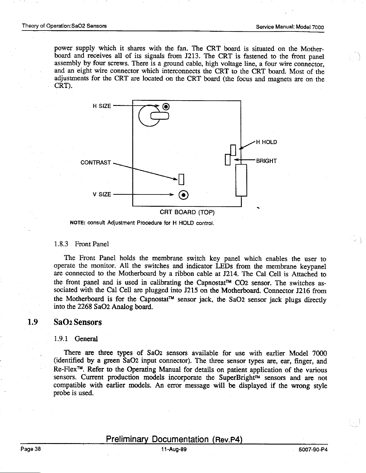
Theory
of
Operation:SaO2
Sensors
Service
Manual:
Model
7000
power
board
assembly
and
adjustments
supply
and
an
eight
receives
by
CRT).
CONTRAST
which
four
wire
for
H
SIZE
V
SIZE
it
all
screws.
connector
the
CRT
|
shares
of
its
signals
There
which
aré
located
with
is a ground
(の
the
fan.
The
from
I213.
cable,
interconnects
on
the
CRT
CRT
BOARD
(TOP)
CRT
The
high
the
CRT
board
board
CRT
is
voltage
to
(the
focus
中
is
situated
fastened
line, a four
the
CRT
and
magnets
[一
WHoup
BRIGHT
on
to
the
wire
board.
the
Mother-
front
panel
connector,
Most
of
are
on
the
the
1.9
NOTE:
consult
1.8.3
operate
are
the
sociated
the
into
SaQ2
1.9.1
(identified
Re-Flex™.
sensors.
Front
The
Front
the
connected
front
panel
with
Motherboard
the
2268
Sensors
General
There
are
by a green
Refer
Current
compatible
probe
is
used.
Adjustment
Panel
Panel
monitor.
to
the
and
the
Cal
is
Sa02
Analog
three
to
production
with
earlier
Procedure
holds
All
Motherboard
is
Cell
for
types
the.
the
the
switches
used
in
are
plugged
the
Capnostat™
board.
of
SaO2
input
Operating
models
models.
for H HOLD
membrane
and
by
a
ribbon
calibrating
into
sensor
SaO2
sensors
connector).
Manual
incorporate
An
error
control.
switch
indicator
cable
the
Capnostat™
J215
on
jack,
available
The
for
details on
the
message
key
panel
LEDs
at
from
J214.
The
CO2
the
Motherboard.
the
SaO2
for
use
three
sensor
patient
SuperBright™
will
be
displayed
which
enables
the
membrane
Cal
Cell
sensor.
The
Connector
sensor
with
types
jack
earlier
are,
application
sensors
if
the
is
Attached
switches
plugs
Model
ear,
finger,
of
the
and
the
wrong
user
keypanel
J216
from
directly
7000
and
various
are
style
to
to
as-
not
Page
38
Preliminary
Documentation
11-Aug-89
(Rev.P4)
5007-90-P4
Page 43
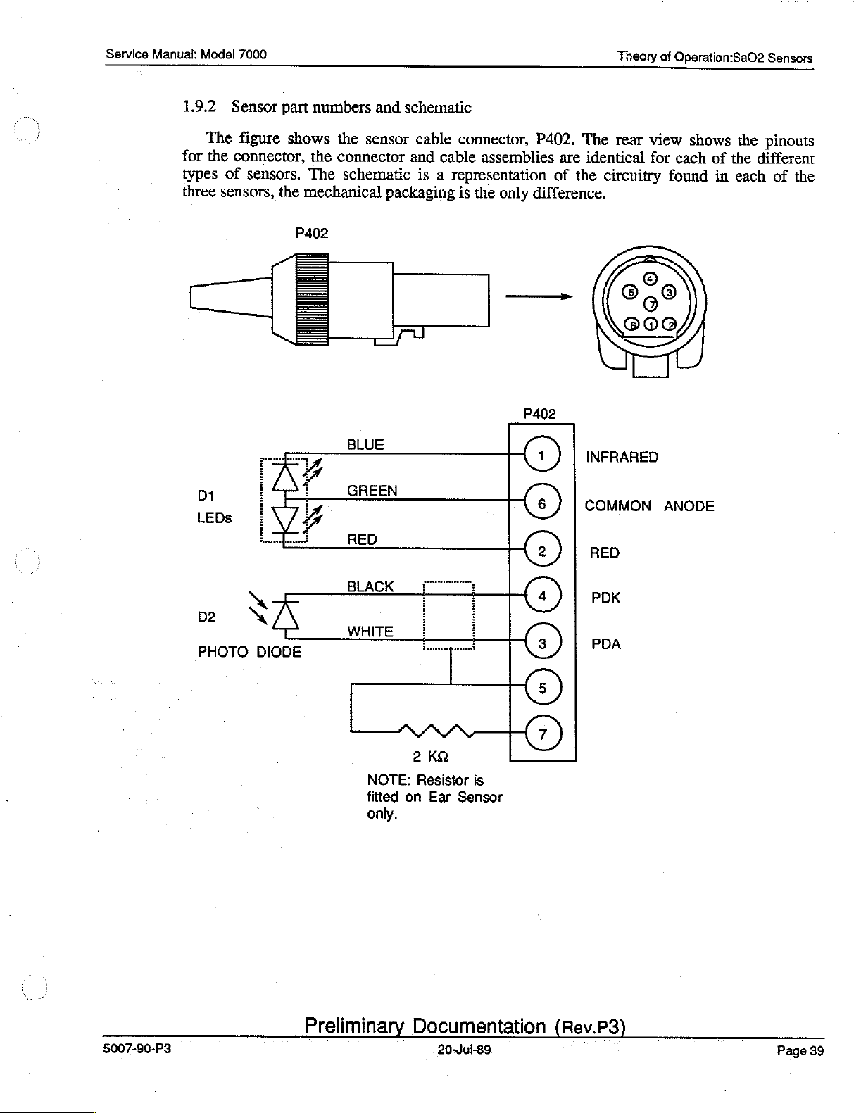
Service
Manual:
Model
7000
Theory
of
Operation:Sa02
Sensors
1.9.2
The
for
the
types
three
D1
LEDs
Sensor
connector,
of
sensors,
part
figure
sensors.
the
iY
V;
numbers
shows
the
The
mechanical
P402
1
A
E
and
the
sensor
connector
schematic
packaging
BLUE
GREEN
RED
schematic
cable
and
connector,
cable
is
a
representation
is
P402.
assemblies
the
only
difference.
P402
6 ) |
The
are
identical
of
the
INFRARED
COMMON
rear
view
for
circuitry
found
ANODE
shows
each
of
in
the
pinouts
the
different
each
of
the
PHOTO
N
DIODE
BLACK
WHITE
NOTE:
fitted
only.
2
KQ
Resistor
on
Ear
is
Sensor
(の
3
©
PDK
PDA
5007-90-P3
Preliminary
Documentation
20-Jul-89
(Rev.P3)
Page
39
Page 44

Theory
of
Operation:CO2
Sensor
Service
Manual:
Model
7000
110
CO2
Sensor
1.10.1
General
The
Novametrix
sophisticated
should
-
repair.
1.10.2
any
Contact
Sensor
The following
tat™
sensor:
LR.
DETECTORS
FLEX
Capnostat"“
circuitry
malfunction
Novametrix
part
numbers
figure
CIRCUIT
HEATER
which
or
Service
and
shows
Sensor
is
housed
damage
occur
Dept.
schematics
a
representation
which
inside
a
with
for
replacement
of
SAPPHIRE
WINDOWS
is
used
gas
a
sensor
the
to
monitor
tight
plastic
replace
or
problem
inside
CO2
levels
case.
For
it
and
do
sensors
configuration
LR.
of
SOURCE
THERMISTOR
contains
this
not
the
Capnos-
reason
attempt
CONNECTOR
HYBRID
Page
40
Preliminary
Documentation
20-Jul-89
(Rev.P3)
5007-90-P3
Page 45
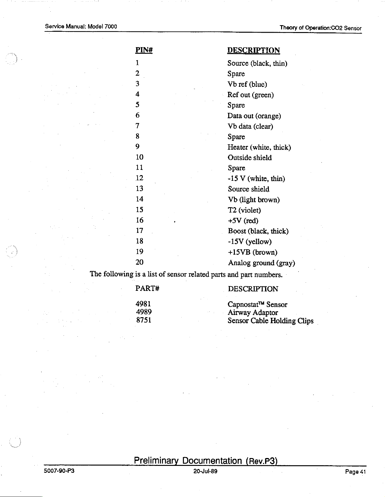
Service
Manual:
Model
7000
Theory
of
Operation:
CO2
Sensor
PIN#
1
2
3
4
5
6
7
8
9
10
11
12
13
14
15
16
17
18
DESCRIPTION
Source
Spare
Vb
Ref
Spare
Data
Vb
Spare
Heater
Outside
Spare
-15 V (white,
Source
Vb
T2
+5V
Boost
-15V
(black,
ref
(blue)
out
(green)
out
(orange)
data
(clear)
(white,
shield
shield
(light
brown)
(violet)
(red)
(black,
(yellow)
thin)
thick)
thin)
thick)
The
following
19
20
is a list
of
PART#
4981
4989
8751
sensor
related
+15VB
Analog
parts
and
DESCRIPTION
Capnostat™
Airway
Sensor
(brown)
ground
part
Adaptor
Cable
(gray)
numbers.
Sensor
Holding
|
Clips
5007-90-P3
Preliminary
Documentation.
(Rev.P3)
Page
41
Page 46
Maintenance
Schedule:General
Service
Manual:
Model
7000
2.0
2.1
2.2
Maintenance
General
All
Novametrix
from
Battery
be
recharge.
point
“AC”
hours
the
date
Novametrix
the
Model
At
under
800-243-3444
the
the
7000.
terms
Maintenance
The
monitor
tor
draws
operated
In
switch
some
the
case
where
on
the
LED
before
of
recommends
customers
(in
on
line
of
the
rear
on
switching
Schedule
Medical
shipment.
the
request,
of a Service
Connecticut
was
shipped
battery
prolonged
unit
the
power
power
will
panel
front
it
for
not
to
panel
on.
Systems
However,
following
Contract.
call
from
even
the
periods
the | position,
Inc.
to
maintenance
Novametrix
Contact
Collect
the
first
turn
is
203-265-7701)
factory
while
24
of
storage
on.
Should
illuminated),
equipment
hours
insure
turned
the
will
provide
the
with a fully
off,
to
allow
or
shipment
this
tum
the
and
is
warrantied
functional
schedules
repair
Novametrix
for
contract
charged
it
is
recommended
ample
the
occur,
allow
plug
monitor
the
for a period
integrity
be
adopted
and
calibration
Service
details.
battery.
time
for
battery
off
monitor
in
the
(ensure
may
of
of
the
with
regard
Department
Since
that the
the
line
to
the
battery
discharge
cord,
that
the
charge
one
year
monitor,
to
services
at
1-
moni-
monitor
to
fully
to
a
set
the
green
for
24
2.3
To
insure
in
the
battery
operated
line
cord
monitor
mately
may
24
Every
limited
frayed
ment
charge.
Fuses
to,
insulation.
for a battery
and
Should
250 V 2A
units.
The
maximum
mode
in
this
should
be
hours
six
are
months
swollen
Line
the
fuse(s)
slow-blow
fuse
is
(line
mode
then
operated
until
be
required
the
or
If
any
replacement.
Cord
need
for
accessed
battery
cord
life
and
disconnected)
the
‘Low
reconnected
normally
to
battery
misshapen
of
these
on
fully
recharge a discharged
should
sides,
conditions
Replacement
replacement
100V
and
120V
from
the
performance,
at
Battery”
and
the
battery
line
power
be
visually
leaking
exist,
be
sure
units;
power
entry
the
least
once
indicator
appears
given
while
the
battery.
inspected
battery
contact
batteries
to
replace
250 V 1A
module
Model
each
7000
month.
on
sufficient
battery
acid,
the
are
with
slow-blow
located
is
for
defects
exposed
Novametrix
subject
the
on
should
The
the
time
recharging.
be
unit
CRT
screen.
to
recharge.
operated
should
Approxi-
including
conductors
Service
to a replacement
same
type
and
for
220 V and
the
rear
panel,
be
The
The
but
not
or
Depart-
rating;
240
V
ensure
Page
42
Preliminary
Documentation
20-Jul-89
(Rev.P3)
5007-90-P3
Page 47
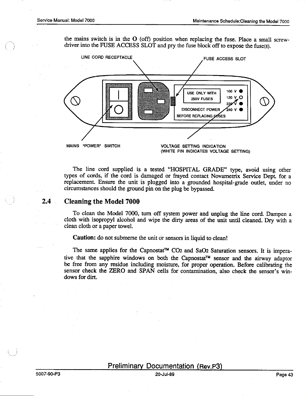
Service
Manual:
the
driver
Model
mains
into
LINE
7000
switch
the
CORD
is
FUSE
RECEPTACLE
in
the
ACCESS
O
(off)
SLOT
position
and
pry
when
the
Maintenance
replacing
fuse
block
FUSE
Schedule:Cleaning
the
fuse.
Place
off
to
expose
ACCESS
SLOT
a
the
fuse(s).
the
Model
small
7000
screw-
O
MAINS
types
replacement.
-
circumstances
The
of
*POWER"
line
cords,
2.4 . Cleaning
To
clean
cloth
with
clean
cloth
SWITCH
cord
supplied
if
the
Ensure
should
the
Model
the
Model
isopropyl
or
a
paper
cord
is
the
unit
the
ground
7000
7000,
alcohol
towel.
is a tested
damaged
is
pin on
turn
and
VOLTAGE
(WHITE
or
plugged
the
off
system
wipe
the
“HOSPITAL
DISCONNECT
BEFORE
SETTING
PIN
frayed
into
a
plug
power
dirty
WA
INDICATES
be
areas
/
/
USE
ONLY
wrH | 10V
250V
FUSES
POWER
REPLACING
7
INDICATION
GRADE”
contact
grounded
bypassed.
and
of
120
V,O
„240 V ©
BUSES
VOLTAGE
Novametrix
hospital-grade
unplug
the
unit
SETTING)
type,
the
until
©
o
avoid
Service
outlet,
line
cord.
cleaned.
using
Dept.
under
Dampen
Dry
other
for
no
with
a
a
a
5007-90-P3
Caution:
The
same
tive that
be
free
from
sensor
dows
check
for
do
the
sapphire
any
the
dirt.
not
submerse
applies
for
windows
residue
ZERO
Preliminary
the
unit
the
Capnostat™
on
including
and
SPAN
Documentation
or
sensors
CO2
both
the
moisture,
cells
for
20-Jul-89
in
liquid
and
Capnostat™
for
contamination,
to
SaOz
proper
clean!
Saturation
sensor
operation.
(Rev.P3)
also
sensors.
and
the
Before
check
It
is
impera-
airway
calibrating
the
sensor’s
adaptor
the
win-
Page
43
Page 48

Operational
Tests:Overview
Service
Manual:
Model
7000
3.0
3.1
3.2
3.3
Operational
Overview
Operational
is
placed
in
the
event a malfunction
tor
and
sensors
Calibration
tact
the
Novametrix
Equipment
*
Line
¢
Capnostat™
*
SaQ2
»
AC
*
Hipot
*
Calibrated
Monitor
testing
into the
and
clinical
(this
Adjustments
Required
cord
(supplied
Sensor
Current leakage
Tester"
Tests
Tests
for
the
Model
environment.
is
reported.
test
does
not
for
such
Service
Sensor
(SuperBright™)
and
Department.
with
with
tester*
N.B.S.
traceable
unit)
Airway
7000
The
This
verify
tests).
PN
600026
Adaptor
should
test
be
tests
may
verifies
performance
Should
performed
also
be
used
the
overall
accuracy
the
unit
fail
on
each
to
operation
of the
any
monitor
spot
of
these
before
check
the
of
the
monitor,
tests
it
unit
moni-
see
con-
NOTE:
sensors
ation.
procedure,
alternative
a
to
3.3.1
The
more
the
Operating
Inspect
inside.
and
in-depth
age,
The
following
will
describe
items
at
selections
set
in
times
explanation
Manual.
the
unit
Check
the
mains
steps
the
BOLD
optional
(but
that
will
for
the
FACE
any
switch
em
will
enable
various
options
indicate
buttons
remove
of
the
are
operation
damage,
rear
panel
to
the O position.
evene
TS
Ime,
vaN
the
listed
the
technician
shake
power
the
technician
and
menus
button
and
and
screen
it
and
entry
to
that
to
bé
explained
from
the
formats
verify
module
there
is
verify
are
part
pressed
in
parenthesis
flow
of
of
is
no
set
for
the
operation
of
the
that
the
procedure).
the
unit
loose
the
proper
system
flow
with
which
please
hardware
volt-
of
the
oper-
the
are
For
refer
Page
44
MAINS
POWER
SWITCH
Preliminary
LINE
CORD
PLUG
Documentation
20-Jul-89
VOLTAGE
(Hev.P3)
SETTING
5007-90-P3
Page 49

Service
Manual:
Model
7000
Operational
Tests:Monitor
Tests
3.3.2
3.3.3.
3.3.4
Inspect
into
the
Verify
sor
into
MAINS
INDICATOR
Place
the
the
front
the
line
rear
panel
that the
the
appropriate
POWER
mains
panel
illuminates.
cord,
verify
power
Capnostat™
power
front
一
entry
switch
no
frayed
module.
and
panel
to
wires
SaQ2
sensors
connector.
the
|
position.
or
other
damage,
are
undamaged,
amm
—
=
2a02
Verify
el
ETCA2
the
plug
am
WenITAR
—
green
the
plug
each
7000 | |
“AC”
line
cord
sen-
FRONT
PANEL
SENSÖR
LED
on
3.3.5
3.3.6
3.3.7
3.3.8
3.3.9
3.3.10
Apply
ify
warm
is
coloration
Press
onds
Press
pears.
with
Place
in
Once
will
ZERO
Progress”
When
SPAN
verify
SPAN
CO2
power
the
green
up”
window
reached
of
and
hold
until
the
and
hold
Select
cell”.
cal
the
Capnostat™
Progress”
the
zero
be
displayed
cell
is
the
span
Complete
all
cell
(mmHg)”
to
the
unit
“ON”
and
the
yellow
Calibration
Press
is
displayed
LED
appears
the
temperature
vertical
the
AUDIO
“OFF”
the
Run/Freeze
Exit.
is
complete
on
and
place
displayed.
is
complete
Please
the
message
and
check
value
equal
by
pressing
on
and
bar
in
the
button
LED
Settings,
sensor
with
into
a
minute:second
“Sensor
the
screen.
it
in
the
remove
windows
the
the
front
then
disappears
stabilizes
window).
on
the
above
softkey
using
the
ZERO
Remove
the
SPAN
following
the
sensor
disappear.
that a waveform
to
the
Span
POWER
panel
(temperature
front
panel
the
button
until
“MONITOR
the
CAL
zero
cell
counter
Complete
the
cell.
message
from
Place
moves
Cell
value
button
illuminates.
when
illuminates.
and
on
the
is
for
approximately
PARAMETERS”
MODE
softkey
verify
that
counts
Place
the
sensor
Capnostat™
Verify
the
from
(this
will
cell”
the
right
that
be
remove
sensor
to
assumes
front
panel.
Verify
proper
indicated
the
temperature
by
」
menu
highlight
that
“Sensor
down.
in
SPAN
sensor
“Sensor
displayed;
the
sensor
back
left
with
that the
Ver-
“Sensor
black
five
sec-
ap-
“Cal
ZERO
cell”
from
the
SPAN
“Sensor
and
into
an
“INST
unit
in
the
is
5007-90-P3
Preliminary
Documentation
20-Jul-89
(Rev.P3)
Page
45
Page 50

Operational
Tests:Monitor
not
zero
Tests
set
menu.
up
for
digital
display).
Press
Cancel Airway
Zero
Service
to
remove
Manual:
the
Model
7000
airway
3.3.11
Place
the
Consult
that
after a few
both
“Pulse”
peak
MENU”).
“ALERT
in
The
the
(unless
step
screen
waveform
SaO2
the
instructions
and
If
any
RESET”
3.4.2).
should
appearances
=
e
sensor
seconds
“SaO2
the
Audio
of the
LED
resemble
“0
==
on
your
supplied
the
Plethysmogram
(%)”. A tone
Pulse
values
will
flash
the
should
JASTC02。
B
person
with
has
been
are
outside
(no
audio
diagram
be
similar.
5?"
in
accordance
the
sensor
waveform
will
sound
defeated
will
below,
С
hiye
to
the
for
proper
appears
with
each
from
of
the
current
sound
the
JUL
|
because
actual
ma)
země
type
that
application.
with
values
pulse
the
limit
values
san
Ed
waveform
“AUDIO
setting
it
was
will
7000
wo
©
is
used.
Verify
for
PULSE
the
defeated
vary
but
才
3.3.12
3.3.13
3.3.14
Press
the
“WAVEFORMS
SaO2
the
and
Press
the
until
Press
Press
Select
The
desired
sensor
Plethysmogram
the
“Pulse”
the.
AUDIO
sound
the
yellow
the
Exit
Alert
CO2
limits
parameter
Set
the
CO2
Exit
softkey
stops
Limits,
Run/Freeze
FROZEN”
from
your
waveform
and
“SaO2"
button,
and
the
“OFF”
softkey,
check
Alert
Limits
can
be
changed
and
parameters
will
return
softkey,
appears
finger,
values
verify
"ALERT
LED
illuminates.
verify
that the
that
an
and
ALERT
verify
by
increase,
RR
RR
the
High
Low
CO2
CO2
to
user
Decrease
High
Low
the
to
verify
at
the
“Probe
window,
will
be
an
alert
RESET”
waveforms
MENU
the
using
Limit = 5
Limit
Limit = 5
Limit = 0
desired
the
real-time
that the
upper
Off
Patient”
the
0.
sounds.
LED
appears.
CO2
the
Move
to
vary
to
= 0
to
values
left
of
and
“ALERT
Press
goes
are
ALERT
off.
no
longer
ALERT
Selection
the
value
200
100
to
100
to
95
then
press
display).
waveform
the
screen.
“ALERT”
RESET"
RESET
Press
frozen.
LIMITS
Bar
of
the
Previous
freezes and
Remove
will
appear
LED
window
will
and
and
hold
to
highlight
flash,
verify
AUDIO
appears.
parameters:
Menu
the
in
the
(the
Page
46
Preliminary
Documentation
20-Jul-89
(Rev.P3)
5007-90-P3
Page 51

Service
Manual:
Modei
7000
Operational
Tests:Monitor
Tests
3.3.15
3.3.16
3.3.17
Select
pears.
and
Set
When
Select
appears
Audio
level
lighted
fault
the
At
PLAY”
pressing
AVERAGING”
pulse
time
switch
the
only.
then
Exit
9402
The
Decrease
the
SaO2
“ALERT
the
the
then
Pulse.
bar
will
even
mode
“SaO2
the
“SaO2
window
the
averaging
display
to
scrolling
To
exit
press
to
return
Alert
limits
System
or
MENU"
activate
Previous
can
softkeys:
parameters
MENU”
select
When
appear.
after
it
is
(or
MENU”
enables
associated
options
times
can
be
speed
this
to
viewing
Limits
and
be
changed
Pulse
Pulse
SaO2
SaO2
to
shown
is
Control
SaO2
power
deliberately
or
of
window
Menu
softkey.
Controls.
the
“AUDIO
The
status
is
removed,
Exit
to
return
select
the
following
softkey.
window
can
be
done
through
deactivate
the
waveform
press
once
real-time
verify
High
Low
High
Low
the
Configure
selected,
that
by
using
Limit
Limit
Limit
Limit
desired
press
Verify
Verify
PULSE
of
the
unless
changed.
to
the
By
pressing
will
appear
Exit).
this
function.
in
Previous
again
waveforms).
a
“SaO2
the
=
35
to
=
30
to
=
20
to
=
0
to
95
values
Exit.
that the
the
MENU”
monitor
the
Press
real-time
Display,
parameters
press
the
to
the
where
Previous
The
Update
The
Plethysmogram
Menu
get
to
ALERT
Move
Selection
250
245
100
then
select
“CONTROL
“SaO2
will
monitor
waveforms).
the
Averaging
to
the
MENU”
appears
be
that
is
Previous
“CONFIGURE
to
be
both
SaO2
Menu
Timer
Speed
return
to
“CONTROL
LIMITS”
Bar,
Previous
MENU”
appears,
the
AUDIO
of
the
powered
Menu
changed
a
“SaO2
averaging
(exiting
acts
softkey
waveform
the
“SaO2
MENU”
menu
Increase,
Menu.
window
select
PULSE
level
high-
up
in
to
retum
SaO2
simply
/
PULSE
to
as
a
toggle
will
control
window
MENU"
(press
ap-
de-
to
DIS-
by
and
real-
5007-90-P3
3.3.18
3.3.19
From
MENU”.
the
Compensation
“BAROMETRIC
changed
ment
760mmHg.
“COMPENSATION
Previous
it
The
MENU”.
This
(Instantaneous,
the
the
“CONTROL
From
“COMPENSATION”
by
pressing
or
decrement
(To
Menu
once
again
to
Configure
Here
enables
End
the
Tidal
this
along
PRESSURE”
softkey
return
Display
the
Breath
softkey.
Preliminary
MENU”
menu
window
with
the
Increase
the
leave
the
MENU”
to
to
the
softkey
Averaging
user
to
select
to
The
Documentation
select
the
user
for
the
Barometric
window.
value
user
or
in
Exit
return
“CO2
will
softkey
“End
Breath,
“Resp.
20-Jui-89
CO2
can
select
corrections
The
or
Decrease
steps
can
select
to
view
to
the
MENU”.
bring
will
Tidal
2
Breath,
Rate
Averaging”
Controls
Compensate
of
Pressure
barometric
to
N20
softkey
softkeys,
of
10
within
Previous
real-time
Menu
waveforms).
“COMPENSATION
up
the
“CONFIGURE
bring
Averaging”
up
4
Breath)
the
from
can
(Rev.P3)
bring
which
Compensation
which
pressure’s
these
the
up
will
brings
will
either
limits
to
return
MENU”
CO2
“AVERAGING”
one
of
four
by
repeatedly
be
set
to
one
the
“CO2
bring
and
up
setting
incre-
of
560
to
Press
then
press
DISPLAY
menu.
options
pressing
of
three
up
O2
the
is
-
the
the
Page
47
Page 52

Operational
Tests:Monitor
Tasts
Service
Manual:
Model
7000
3.3.20
3.3.21
3.3.22
options (Breath
Previous
the
The
Scale
The
Speed
Capnogram
form
“CONTROL
Selection
can
dows
and
one
and
ous
The
to
choose
by
the
of
the
Menu
Display
“DISPLAY
screen
analog
play(digital),
Either
is
Press
of
turned
the
Menu
softkey
softkey
real-time
return
MENU”.
of
the
to
pressing
“AUDIO
three
levels
option
to
return
Controis
CONTROLS”
representation
amplitude
(NOTE:
the
three
off,
however
Previous
to
Breath,
softkey
will
will
to
“CO2
Setup
enter
of
the
the
FEATURES”
for
having
to
the
of
vs.
choices
Menu
2
Breath,
return
to
toggle
waveform
softkey
appropriate
softkey
the
select
MENU”,
“AUDIO
window
“Alert
the
“Keyclick”
“SETUP
one
will
Volume”
from
window.
the
real-time
time
(waveform),
the
“Run
the
to
/
will
remain
default
return
4
Breath)
“CONFIGURE
to
scale
from
of
three
(amplitude
press
FEATURES”
softkeys.
MENU”.
By
Previous
present
will
(by
on
the
“CONTROL
pressing
waveforms
a
Freeze”
is
to
the
is
in
memory
the
waveform
“SET
by
one
speeds
vs.
the
“SETUP
or
Press
appear
pressing
or
off
(toggle
the
triple
waveform,
not
an
UP”
menu.
pressing
DISPLAY”.
CO2
of
two
options
that
will
time).
Press
Menu
“INTERFACES”
the
with
again
MENU”,
Audio
the
the
Audio
function).
MENU”
Display
will
be
changed
or
option
and
option
in
be
stored
(amplitude
Resp
will
View
the
Rate.
(0-50,
affect
Previous
to
here
option
Features
options
Features
Press
bring
softkey
to
a
bargraph
digital
even
Press
0-100).
only
Wave-
reveal
the
softkey
to
select
key),
Previ-
up
either
mode).
if
the
vs.
time).
the
the
user
win-
the
the
an
dis-
unit
3.3.23
Press
dow
the
Dinamap,
softkey
The
the
enables
monitor’s
(toggle
sampling
Sampling
“Pump
The
Inoperative”
Analog
pressed,
to
be
assigned
the
desired
nel
will:
+
turn
the
*
assign
nel
(only
first),
+
will
toggle
available,
*
will
not
ready
Interfaces
the
rear
or
HP
function).
system
System
Output
Pressing
parameters
highlighted
the
parameter a channel
three
assign
user
panel.
Think
softkey
will
Select
to
one
the
number
softkey
to
jet
option
be
softkey
of
consecutively
parameter
channels
any
channels
assigned.
to
reveal
control
Either
Printer,
is
displayed.
the
of
can
also
depressed
will
display
Channels
six
parameters.
off
are
of the
assigned
」
to
the
“INTERFACES”
status
the
or
Capno
of
two
RS232
to
be
activated
and
the
enables
with
if
if
it
available,
each
The
Move
each
it
is
assigned a channel,
was
off
it
channel
the
parameter
the
three
ports
can
Mac
by
pressing
here
the
option
“ANALOG
of
the
Selection
depression.
and
there
will
assign
if
more
if
all
window.
connectors
be
programmed
the
if
it
is
installed.
is
not
installed
OUTPUT”
three
three
The
is
an
the
than
Bar
output
will
Toggle
available
lowest
one
channels
This
win-
located
appropriate
If
on
for
the
then
menu
when
channels
highlight
Chan-
~
chan-
number
channel
are
is
al-
Page
48
Preliminary
Documentation
20-Jul-89
(Rev.P3)
5007-90-P3
Page 53

Service
Manual:
Model
7000
(The
Clear
rameter
saved
if
the
monitor
in
All
Channels
for
reassignment
memory
is
powered
and
will
of
will
up
turn
channel
remain
in
default
all
parameters
numbers.
in
memory
mode.)
off
even
All
the
unless
Operational
the
highlighted
options
deliberately
chosen
changed,
Tests:Monitor
pa-
will
be
or
Tasts
3.3.24
3.3.25
3.3.26
Press
nels
nel
a
on
gle
depression.
corresponding
Press
The
waveforms
Parameters
“SCALE”
the
Pressing
forms
been
change
Right
the
the
return
Previous
to
bring
numbers
“VALUE”
the
Scale
Trend
Exit
current screen
RS232
column.
parameter
and
The
Exit
to
return
Page
(Resp.
will
of
the
softkey
Trend
to
be
chosen
to
show
softkeys
output
to
the
four
Menu
up
and
the
voltage
to
Expansion
selected
it
can
will
to
the
“ANALOG
the
assigned
The
chosen
Scale
corresponding
to
the
softkey
Rate,
bring
trend
to
return
by
be
the
chosen
control
display
has
been
waveform
return
value
will
that
real-time
changes
up
be
to
pressing
expanded
to
CALIBRATION
parameters
column
and
the
change
pin
represents
Pulse,
a
changed
the
“Trend
will
enable
waveform
the
provided
programmed
display.
“ANALOG
will
“Scale”
from
on
the
display.
the
entire
End
Tidal,
window
by
Page”.
selection
Next
by
pressing
and a 12
cursor
the
OUTPUT”.
MENU”
will
be
show
setting
ZERO
rear
panel
either
Trend.
movement.
ZERO,
screen
Sa02).
that
enables
pressing
of
Once
Expand
minute
HP
Think
properly.
Select
window.
displayed,
one
of
(highlighted).
to
HALF
connector
HALF,
display
From
the
appropriate
one
the
Print
jet
printer
Press
there
three
to
to
this
the
“DURATION”
of
the
desired
Trend.
expansion.
Screen
the
Calibrate
The
actual
will
values
FULL
or
four
The
is
Previous
depending
Press
with
will
output
FULL
show
four
display
softkey
trend
waveform
display
The
will
reproduce
connected
Chan-
also
the
wave-
Left
Menu
chan-
be
Tog-
each
the
scale.
trend
Trend
and
press
has
will
and
and
to
5007-90-P3
3.3.27
3.3.28
3.3.29
The
Clear
cause
is
Trend
Press
key,
The
of
this
to
be
erased,
Information).
Exit
verify
Compare
waveform
softkey
“No
was
Compare
UnFreeze
waveform.
Trend
Waveform
softkey
a
prompt
Trend
the
waveforms
Waveform
with
the
pressed
Data
Press
Freeze
press
to
return
current
to
Saved”
softkey
window
No
Waveform
Preliminary
will
clear
all
trend
will
appear
to
to
return
the
to
real
time
freeze.
softkey
will
waveform,
save
an
earlier
will
appear
will
allow
to
toggle
in
Documentation
20-Jul-89
information
to
verify
the
“Trend
display.
enable
the
provided
waveform.
the
“Saved
real
time
back
to a frozen
(Rev.P3)
in
all
that
the
Page”
Press
user
that
If
the
to
the
no
data
Capnogram”
viewing
display.
four
windows,
trend
information
(Yes
will
Run/Freeze
compare a stored
Event/Save
was
saved
window.
of
the
Capnogram
erase
soft-
Marker
then
be-
all
The
Page
49
Page 54

Operational
Tests:Monitor
Tests
Service
Manual:
Medel
7000
3.3.30
3.3.31
Press
be
The
The
selection
selection.
Once
Text:
Next
Print
connected.
Teach
Exit
frozen).
Exit
Teach
Select
has
the
selected
will
display a description
Waveform:
Screen:
Mode:
Compare
The
following
will
Waveform
been
waveform
will
will
print
will
display
Waveform
screen
Select a Waveform
Partial
Onstrucilon
Rebreathing
Curare
Clett
inadequate
Cordiogenic
Hypaventitation
Hyperventilatian
The
The
characteristics:
1.
Height ~ height
concentration,
2.
Baseline - teseline
‘and
3.
Frequency
determined
4.
Shape - the
and
bring
made,
toggle
Seal
Oscitiations
Waveform
produced
capnogrem
shauis
mechenicai
sad
dy
respiratory
cupnogram’s
pisteas,
the
will
Display
is
to
the
screen
the
ls
ventitation.
Rhythm = frequency
user
toggle
previous
to
exit,
will
appear:
|
ANS
EEN
by
exholed
be
dependent
should
displayed,
of
the
CUZ haz p uninua
analyzed
far
an
tha
be
zere
for
rate,
axcending
back
between
Waveform
the
chosen
next
the
end
and
lima,
to
choice.
display
screen
select
57
EZ
following
tide!
beth-spontaneous
rhythm
descending
зо
1a | Teach
emip!
shape, | Waveform
COZ
aro
Umb
Teach
Enit
Select
Waveform
Display
the
previous
each
of
will
the
following
waveform.
provided
display.
Mode
display.
the
eight
display
options
the
HP
(waveforms
choices.
an
example
are
Think
must
Once
of
available;
jet
is
properly
a
the
3.3.32
3.3.33
3.3.34
3.3.35
Press
the
Exit
softkey
Press
Exit
again
The
Event/Save
waveforms
display
memory
The
waveform
mode.
Remove
adaptor
when
when
and
can
the
Capnostat™
to
the
pressed.
sensor.
duce a waveform
Check
Verify
Check
instead)
press
so
AUDIO
as
the
waveform
steady
the
response
“Resp(br/m)"
values
and
to
avoid
range.
to
return
to
return
Marker
pressed.
These
be
seen
will
also
Slowly
on
the
for
and a “Resp(br/m)”
to
see
if
verify
setting
an
to
to
real
time
softkey
The
pointer
pointers
on
the
trend
be
stored
sensor
breath
screen.
erratic
and
the
“ETCO2”
they
yellow
noise
are
alarm
the
“WAVEFORMS
display.
will
place
are
waveforms
for
from
through
and
(the
within
“OFF”
due
to
FROZEN”
a
pointer
arrow
will
stored
not
with
when
comparison
the
Span
the
in
Cell
airway
dropouts.
value
other
than
“INST”
the
LED
option
limits
presently
goes
out..
“Resp(br/m)”
arrow
be
visible
the
in
Trend
the
and
adaptor
zero.
may
If
or
“ETCO2”
display.
on
both
on
waveforms
Mode.
“Compare
attach
the
so
be
enabled
listed,
not,
edit
values
©
real-time
the
digital
in
trend
Waveform”
airway
as
to
pro-
here
if
they
are
the
limits
out
of
Page
50
Preliminary
Documentation
20-Jul-89
(Rev.P3)
5007-90-P3
Page 55

Service
Manual:
Mode!
7000
+
Press
LIMITS”
softkeys
time display
as
before
Alert
Limits,
window
to
edit
by
until a “Resp”
then
press
use
the
the
limits
pressing
value
Move
to
the
Exit.
Begin
is
present.
CO2
Alert
Selection
required
Limits.
Bar,
values.
breathing
At
the
Increase,
Return
into
the
Operational
“CO2
and
to
the
airway
ALERT
Decrease
Real
adaptor
Tests:Safety
Checks
34
3.3.36
3.3.37
3.3.38
3.3.39
3.3.40
3.3.41
Stop
Verify
tone
Verify
Check
minute:second
Verify
Press
Confirm
Verify
Press
Verify
Press
LED
Safety
3.4.1
Power
Place
the
breathing
that
sounds
the
the
the
the
that
the
the
and
illuminates
Checks
down
the
line
cord
into
after a while
from
the
“Resp(brim”
upper
“ALERT
AUDIO
that the
the 2 MIN
AUDIO
continuous
hold
mains
right
counter
button
continuous
button
the
and
the
monitor
power
from
the
the
airway
unit.
value
portion
which
RESET”
on
LED
again.
tone
AUDIO
the
wall
adaptor.
“ALERT”
is
zero.
of the
will
increment.
LED
on
the
front
tone
stops.
illuminates.
returns.
button
tone
by
switch
for
stops.
pressing
on
socket.
is
displayed
screen
the
front
panel.
five
the
the
rear
on
for
“No
panel
blinks.
seconds,
POWER
panel
the
screen
Respiration”
verify
to
that
button
the O position
on
and a continuous
followed
the
yellow
the
front
and
by
a
“OFF”
panel.
unplug
5007-90-P3
3.42
*
*
*
3.4.3.
3.4.4
3.4.5
age.
Place
the
mains
Measure
the
grounded,
line
cord:
the
ungrounded,
ungrounded
Verify
240
VAC).
Apply
gether)
Apply
connector
and
the
leakage
2.5
KV
and
chassis
1.5
KV
(shorted
Preliminary
switch
leakage
polarity
does
between
ground
between
together)
located
current
on
the
from
reversed.
not
exceed
the
Hot
and
for
no
less
the
chassis
for
no
Documentation
20-Jui-89
rear
panel
the
monitor’s
25
pA
Neutral
to
(50
sides
pA
than 1 minute.
ground
less
and
than 1 minute.
(Rev.P3)
the | position.
chassis
for
of
Verify
the
units
the
pins
Verify
with
the
operating
line
cord
no
arcs
on
the
no
unit
at
(shorted
or
leakage.
“SaO2
arcs
on
and
220
to-
INPUT”
or
leak-
Page
/
]
51
Page 56

Calibration
and
Adjustments:Introduction
Service
Manual:
Model
7000
4.0
41
4.2
Calibration
Introduction
The
Model
internal
(except
Novametrix
ing
with
the
nel,
Dept.
guired.
along
the
electronics
battery
Calibration
the
unit.
problem.
or
returned
before
In
order
The
with
accuracy
Calibration
Before
stored
which
then
tings
parameters
it
was
the
parameters
perform
7000
and
trained
procedure
Should
The
adjustment
to
returning
to
correctly
TB500A
faulty
of
probe
the
Procedure
proceeding
received.
the
following;
and
Sa02
be
Adjustments
is a highly
of
the
unit
fuses),
technicians.
any
the
any
with
recorded
will
all
was
problems
tests
Novametrix
equipment
calibrate
simulates
conditions.
section
the
If
the
be
at
complex
require
required
In
order
included
occur
should
factory
to
the
the
Model
various
The
and
is
available
Calibration
so
that
monitor
the
has
default
microprocessor
no
regular
adjustments
to
verify
which
the
only
for
factory.
7000
saturation
TB500A
the
monitor
not
settings.
the
would
Adjustment
be
performed
repair.
SaO2
is
the
from
Procedure
been
controlled
scheduled
are
performed
accuracy
determine
procedure
Please
section
levels
only
Novametrix
can
used
To
at
acceptable
it
is
suggested
be
returned
(just
record
monitoring
maintenance
at
of
the
monitor
any
possible
will
by
qualified
contact
the
different
received
the
Novametrix
TB500A
method
Service
in
current
Department.
that
unit.
or
calibration
the
factory
the
malfunctions
aid
in
service
test
box
signal
of
verifying
the
the
manner
from
the
parameter
The
by
follow-
isolating
person-
Service
is
re-
strengths
currently
with
factory)
set-
ed
*
The
following
below.
Apply
power
key.
Press
PARAMETERS"
procedure
The
monitor
(see
and
Lua
steps
hold
window
can
4.2.2-4.2.4
the
Run/Freeze
appears.
assumes
easily
be
of
Record
the
unit
reset
(
)
Uè
DEL
L
E
this
section).
softkey
the
is
to
these
z
재대
rl
se
n
mass
Press
until
the
parameters.
set
to
its
settings
7000
зимы
©
©
6
the
default
Run
“MONITOR
settings,
by
simultaneously
soft-
these
pressing
are
list-
Page
52
Preliminary
Documentation
20-Jul-89
(Rev.P3)
5007-90-P3
Page 57

Service
Manual:
Model
the
7000
ALERT
RESET
—sereemappeárs.
and
|
ㆍ
POWER
to
buttons
一
一
;
eee
factory
default
located
С
Omit...
|
(OZO
С)
Calibration
on
the
sem
эн
cer]
and
Adjustments:Calibration
front
7000
06
panel
2007
until
一
一
~
2
Procedure
the
following
Note:
justed
of
the
tered
if
Alert
Audio
Audio
CO2
Compensation
Display
Display
Display
No-
Trend
The
span
to
the
particular
monitor,
the
Limits:
Features:
Pulse
Calibration:
Note:
be
cell
tant
Page:
before
unit
is
ETCO2
Beep
The
adjusted
or
on
that
the
(CO2
Screen:
Parameter
Averaging:
ion-
Duration-4
Sa02
cell
the
to
operate
90-10,
Alert
Volume-High,
(SaQ2
Cal
with
span
cell
to
the
the
rear
correct
portion)
Waveform
(CO2):
End
Rate-8
Timer:
hours,
50-100,
m
value
span
will
cell
monitor
correctly.
Resp
99-2,
portion):
cal
value
particular
of
value
ETCO2
Tidal
Pulse
cell
will
the
monitor,
be
entered
:
O2
view,
CO2
and
second
on
display
0-250)
High
(not
<
displayed
Resp.
default
value,
as
is
shipped.
Default
SaQ2
100-80,
Keyclick-On
with
gas),
default
span
60%,
scale
averaging.
scale-full
to
cell
value,
before
if
the
N2O0-No,
0-100
(not
Rate-4
5
to
57
listed
It
Settings
Pulse
span
cell
57
mmHg.
as
the
unit
is
to
Barometric
mmHg,
INST
Breath
(ETCO2
must
3282
22002
mmHg.
on
is
value
listed
monitor
operate
display
CO2)
Averaging,
0-100,
However,
the
front
important
150-40
set
However,
on
is
correctly.
Pressure-760
speed
Resp
O
01702
[一
of
the
that
the
to
57
mmHg
this
the
front
of
shipped.
Saturation
It
mmHg
12.5
0-150,
this
setting
span
cell
correct
setting
mm/sec
the
is
and
will
span
impor-
Pulse
will
or
on
value
be
the
be
ad-
rear
en-
5007-90-P3
Preliminary
Documentation
20-Jul-89
(Rev.P3)
Page
53
Page 58
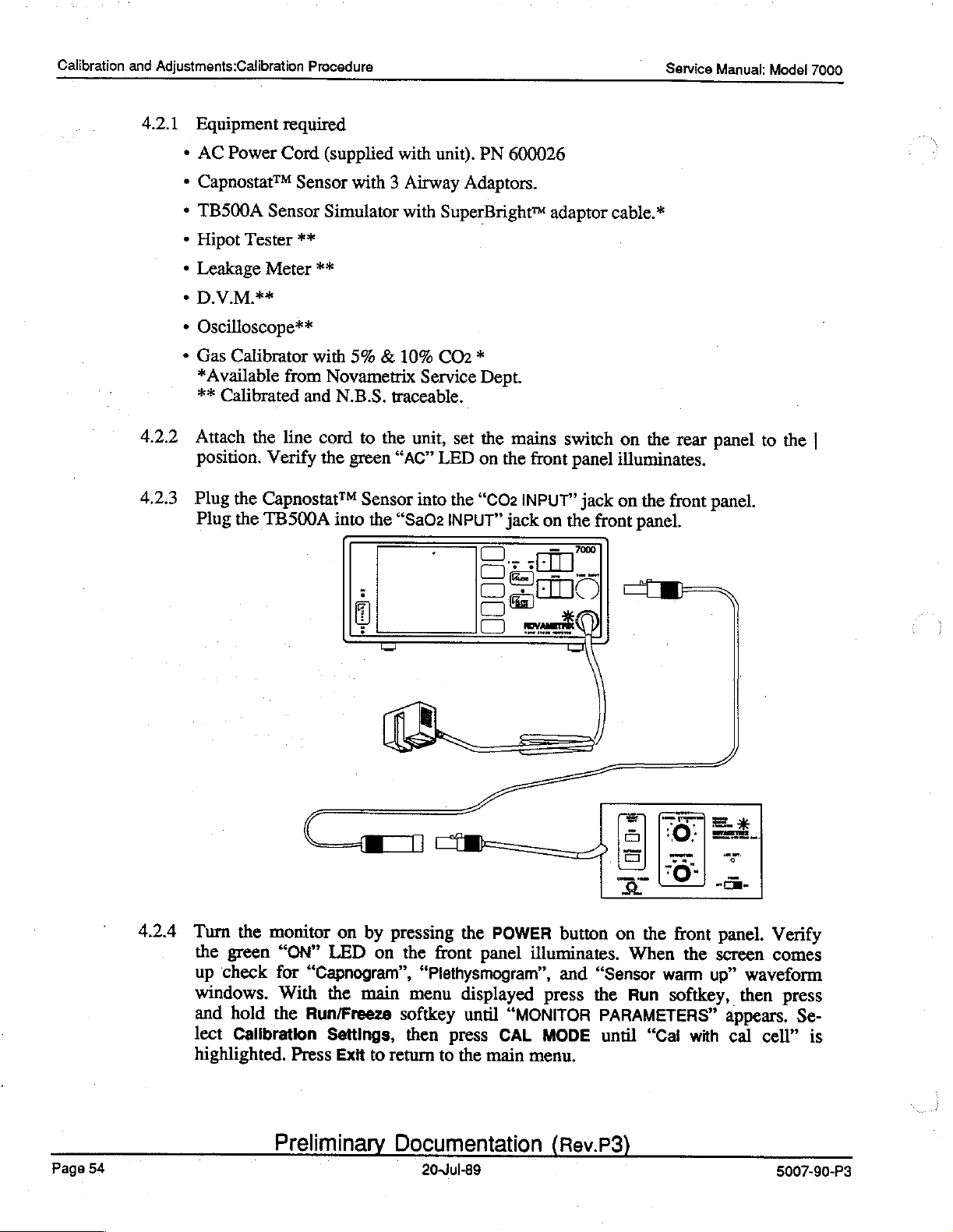
Calibration
and
Adjustments:Calibration
Procedure
Service
Manual:
Model
7000
4.2.1
4.22
4.2.3
Equipment
*
AC
Power
+
CapnostatTM
*
TB500A
*
Hipot
*
Leakage
*
D.V.M.**
*
Oscilloscope**
+
Gas
Calibrator
*Available
**
Calibrated
Attach
position.
Plug
the
the
Plug
required
Cord
Sensor
Tester
Meter
the line
Verify
Capnostat™
TB5004
(supplied
Sensor
Simulator
**
**
with
from
and
cord
the
with
with 3 Airway
with
5% & 10%
Novametrix
N.B.S.
into
to
the
green
Sensor
the
traceable.
“AC”
“SaQ2
unit).
PN
Adaptors.
SuperBright™
CO2
*
Service
unit,
into
set
LED
the
INPUT”
Dept.
the
on
“CO2
600026
mains
the
front
INPUT”
on
jack
adaptor
switch
panel
jack
front
the
cable.*
on
the
rear
illuminates.
on
the
front
panel.
panel
panel.
to
the
|
4.2.4
Tum
the
monitor
the
green
up
check
windows.
and
hold
lect
highlighted.
“ON”
for
With
the
Callbration
Press
on
by
pressing
LED
on
the
“Capnogram”,
the
main
Run/Freeze
Settings,
Exit
softkey
to
return
the
POWER
front
panel
“Plethysmogram”,
menu
then
displayed
until
press
to
the
CAL
main
“MONITOR
button
illuminates.
and
press
on
When
“Sensor
the
Run
PARAMETERS”
MODE
until
menu.
the
front
the
warm
softkey,
“Cai
with
panel.
screen
up”
waveform
then
appears.
cal
cell”
Verify
comes
press
Se-
is
Page
54
Preliminary
Documentation
20-Jul-89
(Rev.P3)
5007-90-P3
Page 59

Service
Manuat:
Model
7000
Calibration
and
Adjustments:Calibration
Procedure
4.2.5
4.2.6
4.2.7
4.2.8
Once
ZERO
Place
remove
struction
Press
Verify
ue
with
Set
Press
pears
Press
message
(refer
to
the
cell
the
the
Cancel
a
is
equal
no
spikes
the
unit
*
From
the
“CO2
use
End
Exit.
and
(the
Display
to
“MONITOR
sensor
and
wait
sensor
sensor
windows
Airway
waveform
to
that
or
to
display
the
main
Menu”
Tidal
hold
Run/Freeze
CPU
software
Parameter,
should
Error
be
Messages
PARAMETERS”,
is
up
to
for
“Sensor
into
the
from
the
disappear
Zero.
moves
of
the
dropouts.
Instantaneous
menu
press
press
Configure
to
highlight
revision
the
displayed.
temperature,
SPAN
cell”
appears
place
the
from
right
SPAN
System
“Instantaneous
until
level
“SENSOR
Verify
section).
place
ZERO
cell,
sensor
to
left
Cell
CO2
as
Control,
Display,
the
“MONITOR
can
the
Press
the
Complete
when
remove
back
and
value.
STATUS”
Ensure
follows:
press
then
(INST
be
read
other
the
Previous
Capnostat™
Place
“Sensor
the
into
that
CO2
select
from
will
parameters
SPAN
sensor,
the
SPAN
the
“INST
the
Controls
Averaging,
CO2)”.
PARAMETERS”
here).
appear
Menu
Sensor
sensor
complete
as
soon
cell.
CO2(mmHg)”
waveform
at
Press
and
are
softkey
in
SPAN
window
a
set
into
Please
as
the
is
steady
“no
as
required
to
return
the
cell”.
in-
val-
ap-
error”
4.2.9
4.2.10
Press
TINGS”
Press
C02”
When
CAL
is
trois.
At
the
cell
and
not
be
Press
the
Zero,
airway
the
Calibration
window.
MODE
highlighted,
the
main
“CO2
attach
introduced
MENU”
it
wait
screen
to
for
adaptor
so
to
then
the
any
the
and
Settings
as
to
highlight
press
appears
select
airway
CO?
Zero
set
it
softkey
“Cal
Exit.
press
Calibration,
adaptor.
gas.
process
for
5%
to
COz.
to
bring
with
System
remove
Set
the
end,
Let
apo
p
up
gas”,
press
Control,
the
sensor
then
attach
the
gas
the
“CALIBRATION
CAL
then
select
sensor
in
a
place
the
flow
for
GAS
until
CO2
from
the
where
gas
calibrator
a
few
SET-
“5%
Con-
SPAN
it
will
to
minutes
]
5007-90-P3
Preliminary
Documentation
20-Jul-89
—
(Rev.P3)
Page
55
Page 60
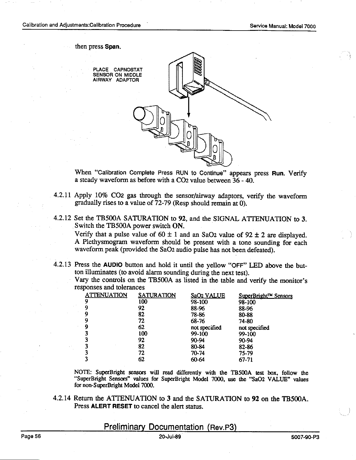
Calibration
and
Adjustments:Calibration
then
press
Procedure
Span.
`
Service
Manual:
Mode!
7000
4.2.11
4.2.12
PLACE
SENSOR
AIRWAY
When
a
Apply
gradually
Set
Switch
Verify
A
waveform
“Calibration
steady
waveform
10%
rises
the
TB500A
the
that
Plethysmogram
peak
CAPNOSTAT
ON
MIDDLE
ADAPTOR
CO2
to
a
SATURATION
TB500A
a
pulse
(provided
Complete
before
as
gas
through
value
of
power
value
waveform
Press
with
the
72-79
switch
of
60
should
the
SaO2
RUN
to
value
CO2
a
sensor/airway
(Resp
to
92,
should
and
ON.
+
1
and
an
be
present
audio
pulse
Continue”
between
adaptors,
remain
the
SIGNAL
SaOz
value
with
has
not
appears
36
40.
-
press
verify
at
0).
ATTENUATION
of
92
a
tone
been
defeated).
Run.
the
waveform
+
2
are
displayed.
sounding
Verify
to
for
each
3.
Page
56
4.2.13
4.2.14
Press
the
AUDIO
ton
illuminates
Vary
the
controls
responses
ATTENUATION
and
9
9
9
9
9
3
3
3
3
3
NOTE:
“SuperBright
for
Return
Press
SuperBright
non-SuperBright
the
ATTENUATION
ALERT
Preliminary
button
(to
avoid
on
tolerances
sensors
Sensors”
RESET
values
Model
to
and
hold
it
alarm
the
SATURATION
sounding
TB500A
100
92
82
72
62
100
92
82
72
62
will
read
for
SuperBright
7000.
to 3 and
cancel
the
alert
Documentation
20-Jul-89
until
the
yellow
as
listed
during
SaQ2
in
VAL!
the
the
next
table
98-100
88-96
78-86
68-76 74-80
not
specified
99-100
90-94
80-84
70-74
60-64
differently
the
with
the
Model
7000,
SATURATION
status.
(Rev.P3)
“OFF”
test).
and
SuperBright™
98-100
88-96
80-88
not
99-100
90-94
82-86
75-79
67-71
TBS00A
use
the
to
LED
above
verify
specified
“SaO2
test
92 on
the
box,
VALUE”
the
the
but-
monitor’s
Sensors
follow
values
TB500A.
5007-90-P3
the
Page 61
Service
Manual:
Model
7000
Calibration
and
Adjustments:Calibration
Procedure
4.2.15
4.2.16
4.2.17
4.2.18
Press
bring
“INTERFACES”
Press
appears
and
Press
brate
Measure
ZERO
for
Verify
gle
System
the
“SETUP
the
verify
Resp.
Rate
Previous
Channels,
the
(Scale
CH1;
10
proper
Scale
to
below:
PIN
2(CH1)
10
(CH2)
9
(CH3)
Press
Channels.
Press
Move
assign
Use
assign
Press
Toggle
Previous
Clear
Selection
it
CHI.
the
Move
CH2.
Move
Channel.
Controls,
MENU”.
window.
Select
Channels
that
is
assigned
Menu
verify
outputs
is
changed
for
CH2;
HALF
switch
(Channel)
Menu
Al!
Channels,
Bar
Selection
Selection
when
Select
Capnogram
CH2
to
return
that
a
“ANALOG
on
J103
by
pressing
and
9
for
and
FULL
from
ZERO
PARAMETER
Capnogram
Resp.
End
.to
return
verify
to
highlight
Bar
Bar
to
the
“CONTROL
Interfaces
softkey,
is
(these
when
assigned
are
to
the
the
“INTERFACES”
CALIBRATION
(rear
panel
connector),
Toggle
CH3)
are
scale
to
HALF
all
zero
voltages
Rate
Tidal
to.
“ANALOG
that
all
the
Plethysmogram,
to
highlight
highlight Pulse
Saturation,
MENU”
then
select
“SELECT
Chl;
End
default
settings).
MENU”
Scale),
volts.
at
the
to
FULL.
HALE
1.96
volts/3.92
1.96
volts/3.92
0.98
volts/1.96
OUTPUT”,
parameters
then
Rate,
appears
Analog
ANALOG
Tidal
window.
appears.
with
verify
output
The
are
press
press
Assign
press
Output
is
assigned
the
“Scale”
the
outputs
by
values
VALUES
volts
volts
volts
then
o
“OFF”.
Toggle
Toggle
CH3
Setup
at
CHANNELS”
CH3;
Select
set
(pins
pressing
are
listed
select
Select
Use
Channel
Channel
by
pressing
to
the
Call-
to
2
Tog-
the
to
to
5007-90-P3
4.2.19
4.2.20
4.2.21
To
return
brate
Channels
er.
Confirm
Scale
softkey
Press
by
the
pressing
to
the
softkey,
the
proper
to
change
PIN
(Channel)
2
(CH1)
10
(CH2)
9
(CH3)
Exit
softkey
the
POWER
Preliminary
“INTERFACES”
verify
ZERO,
the
HALF,
Scale.
PARAMETER
Plethysmogram
Saturation
Pulse
to
return
button
Documentation
20-Jul-89
menu
the
parameters
Rate
to
the
on
the
press
and
FULL
real-time
front
panel.
Previous
are
assigned
voltages
HALE,
1.24
volts/2.49
0.98
volts/1.96
2.48
volts/4.96
display.
(Rev.P3)
Menu,
as
by
pressing
VALUES
Power
select
described
the
volts
volts
volts
down
the
earli-
Toggle
the
Cali-
unit
Page
57
Page 62

Calibration
and
Adjustments:Adjustment
Procedure
Service
Manual:
Model
7000
4.3
Adjustment
The
following
malfunction
are
highly
adhered
ing
section
adjustments
Operation”
to
check
4.3.1
*
+
*
*
+
+
sensitive
to
at
section
on
suspect
Equipment
Line
cord
TB500A
2410-01
Oscilloscope**
D.VM**
CapnostatTM
*
Available
**
Calibrated
Procedure
procedure
or
breakdown
all
times
“Assembly
on
the
monitor.
holds
boards.
Required:
(supplied
Sensor
(digital
Sensor
from
and
should
occurs
to
static
when
handling
and
In
several
with
Simulator
bds.);
2411-01
Novametrix
N.B.S.
only
be
with
the
electricity
the
internal
Disassembly
addition
bits
unit)
with
to
of
necessary
PN600026
SuperBright™
(input
Service
traceable.
performed
unit.
and
Instructions”
the
bds.)
Dept.
by
The
electronics
proper
components.
steps
and
information
adaptor
extender
qualified
used
grounding
Please
when
tests
listed
cable.*
cards.*
personnel
in
the
techniques
consult
performing
here
the
and
possible
in
the
Model
should
the
repairs
“Theory
test
event
a
7000
be
follow-
or
of
points
432
4.3.3
4.3.4
Follow
cord
boards
Boards
*
Memory
+
CPU
*
Video
+
CO2
+
SaO2
Remove
cord
on
the
between
the
right
erboard
Install
Verify
verify
ble
with
the
power
the
disassembly
is
disconnected
from
the
to
be
removed
Front
End
Front
End
the
Power
to
the
rear
front
“GND”
of
the
if
necessary.
the
Power
the
“AC”
the
“ON”
no
video),
supply
card
(two
(two
panel
panel
and
CRT.
Supply
LED
LED
board,
instructions
and
no
power
cage
and
set
from
the
card
board
combo)
board
combo)
Supply
and
place
will
not
“REG
Verify
Set
the
board
light).
OUT”
+14.5
mains
board,
illuminates.
illuminates,
and
the
fan
use
the
GND
in
the
is
applied
aside
(ensure
cage:
and
disconnect
the
mains
Using
test
points
volts + .002
switch
set
Press
the
turns
on
the
mains
the
CRT
on.
point
Monitor
on
following
to
proper
the
switch
the
in
D.V.M.
on
volts,
the
rear
panel
switch
POWER
lights
the
up
the
board
section
the
static
battery.
(ensure
unit),
control
remove
Attach
the | position
measure
the
Motherboard
adjust
button
(retrace
VR1
to
O.
on
the
rear
on
the
lines
following
as
ground
reference.
the line
all
handling).
the line
(“AC”
the
LED
voltage
found
on
the
Moth-
panel
front
will
test
to
panel,
be
visi-
points
the
to
|.
on
Page
58
Preliminary
Documentation
20-Jul-89
(Rev.P3)
5007-90-P3
Page 63
Service
Manual:
Model
7000
Calibration
and
Adjustments:Adjustment
Procedure
4.3.5
4.3.6
NOTE:
points
quire
Press
place
their
Both
on
further
the
the
appropriate
appears.
in
working
If
the
screen
following
*
Power
+
Install
board
-15 У ТР.........
+15 У
VR1
the
(low
board
ТР........
are
adjusting.
POWER
CPU,
button
Memory,
card
The
screen
order,
is
will
therefore
not stable
manner:
down
the
monitor.
the
card
extender
to
the
card
extender.
BAT
turn
factory
on
the
CO2
slots.
appear
reconnect
then
in
nn
off
set
front
Front
Press
“wavy”
the
the
-14.5 V to
ωω
+14.5 V to
„+49Vto+51V
+18 V to
+13 V to
point)
to
and
special
panel,
End,
the
POWER
unless
the
battery.
CRT
requires
Video
Board’s
-15.5
+15.5
+25
V
+15V
the
“VOLTAGE
tolerances
verify
and
the
SaO2
button
the
battery
alignment,
slot
V
V
and
unit
Front
and
then
ADJUST”
should
powers
End
verify
is
connected
this
is
attach
not
re-
down.
boards
the
screen
done
the
Re-
into
and
in
the
Video
4.3.7
+
Install a SPDT
the
line
*
Toggle
er
to
the
*
Adjust
play
is
*
Toggle
locked
+
Seal
the
The
remaining
further
er
will
To
tuning
geometric
help
access
¢
Press
Run
e
Press
“MONITOR
+
Select
appears
either
the
in
SPDT
monitor.
the H HOLD
vertical
the
SPDT
on
screen.
adjustment
controls
(consult
alignment
in
adjusting
this
screén
from
the
and
hold
PARAMETERS”
Display
press
Parameters,
the
switch
or
out
switch
potentiometer
and
stationary
switch
on
on
“Theory
of the
the
perform
waveform
the
Run/Freeze
third
softkey
in
line
with
of
circuit).
so
the
or
so
the
the
CRT
the
CRT
of
CRT, a test
yoke’s
window
magnets
the
following:
screen.
will
when
from
pin
A21
line
is
out
of
on
the
slowly
line
rolling.
is
in
circuit
board.
are
factory
Operation"
grid
to
key
to
freeze
appear.
the
“SENSOR
the top
(it
on
connector
circuit
CRT
board
(closed),
adjusted
for
more
is
stored
acquire
the
waveforms,
STATUS”
will
not
P206
(open),
so
and
then
that
the
verify
the
should
information).
in
video
the
best
window
be
labelled),
memory
possible
a
(to
switch
apply
pow-
video
video
reguire
For
prop-
which
screen.
dis-
is
no
5007-90-P3
Preliminary
Documentation
20-Jul-89
(Rev.P3)
Page
59
Page 64

Calibration
and
Adjustments:Adjustment
the
following
To
exit
will
PARAMETERS”
plays).
Procedure
diagram
press
reappear.
any
Press
window
will
of
the
Previous
appear
softkeys
(or
press
on
and
Menu
Run
the
the
screen:
“SENSOR
to
retum
to
return
STATUS”
to
to
the
the
“MONITOR
waveform
Service
window
dis-
Manual:
Model
7000
4.3.8
4.3.9
4.3.10
Press
highlight
and
Power
Then
verify
or
the
Time
the
Decrease
down
power
that
flashes
parameter
keys.
the
the
it
blinks
at
a
microprocessor
Monitor
ground
front
mately
TP4
(TEMP)
reference.
panel.
volts,
+5
The
Date
softkey
to
Press
unit
and
unit
back
on
and
much
circuitry
faster
on
on
Plug
the
voltage
will
it
then
if
be
changed
Run
to
return
place
up.
Check
off
at
rate
board,
the
2418
Capnostat™
should
stabilize
requires
the
adjustment,
and
to
the
CO2
Front
the
LED
editing
waveform
approximately
there
is
most
try
turning
CO2
Front
sensor
start
at
=
-5
volts.
=3.5
the
End
on
power
End
into
volts
the
is
done
display.
boards
the
2421
1
Hz
(if
probably
off
board,
its
appropriate
and
Select
through
on
board
it
stays
a
problem
then
on
use
then
Parameter
the
Increase
a
card
extender.
(larger)
continually
with
again).
TP2
(GND)
jack
rise
to
approxi-
on
will
and
on
the
as
the
Page
60
Preliminary
Documentation
20-Jul-89
(Rev.P3)
5007-90-P3
Page 65

Service
Manual:
Model
7009
Calibration
and
Adjustments:Adjustment
Procedure
4.3.11
4.3.12
4.3.13
Measure
End
boards)
P3-19
P2-22
P3-25
TP10
TP5
Monitor
Monitor
NOTE:
2.08
to
2.10msec
the
(HTR)
(-80
P3-14
+5
V>
ον
TP11
If
the
msec
following
with
the
D.V.M.
VOLTS)
with
the
(VS)
on
pulse
width
—>
|
<—
points
oscilloscope,
the
—
20.80
to21.00
board
is
out
msec
on
the
-15
+15
+5
3.5
-80
under
of
specification
msec
2418
volts
volts
volts
volts
volts
verify
test,
|
board
+
the
freq. = 4800
verify
(smaller
3
volts
following
the
check
of
(only
when
waveform:
Hz
following
tolerance
+5V
-15V
the
two
sensor
is
waveform:
of
C74.
CO2
Front
installed)
5007-90-P3
4.3.14
4.3.15
Measure
waveforms:
Measure
-20
to
TP3
TP8
-60
(A)
and
TP13
20.80
1021.00
(VBREF)
VDC.
and
Preliminary
(S/H)
msec
msec
TP6
with
(VBDATA).
the
Documentation
20-Jul-89
oscilloscope,
2.08
-2.10
Verify
DC
voltages
(Rev.P3)
verify
msec
the
following
between
Page
61
Page 66

Calibration
and
Adjustments:Adjustment
Procedure
Service
Manual:
Model
7000
4.3.16
4.3.17
Monitor TP7
Check
would
between
Scope
for
indicate
the
pin
12
(D
CH)
and
|-=—
excessive
a
problem
Sensor
and
and
pin
5V
ov>
TP9
to
noise
the
11
of
(R
20.80
21.00
riding
with
unit.
J3,
|
20.80
+
CH),
msec
msec
on
the
verify
msec
.05
msec
verify
—
the
the
|
decay
Capnostat™
the
following
一
一
e
following
~€—
AMPLITUDE
VARY
ον
portion
Sensor
waveforms
一
waveforms:
MAY
of
the
waveform,
or
bad
(same
for
this
connections
each):
4.3.18
4.3.19
4.3.20
4.3.21
4.3.22
Monitor
volt
Remove
board
should
TPS
Plug
be
calibrate
appears
When
the
Remove
remove
Reinsert
from
value
Plug
sure
PIN
offset
the
should
appear
on
2418
the
sensor
reached
with
on
the
span
to
the
the
the
the
is
equal
the
TB500A
to
use
SATURATION:
9
of
J3.
from
the
zero
sensor
flash
at
in
the
(2409)
back
then
place
the
Cal
the
screen.
ZERO
is
complete.
sensor
sensor
from
sensor
screen,
to
that
verify
sensor
the
adaptor
92
Verify
baseline
from
the
half
the
Capnogram
is
-12
volts.
into
the
the
sensor
Cells).
complete
from
the
the
cell”
into
the
that
of
the
SPAN
simulator
cable,
a
2
Vp-p
jack
rate
waveform
front
into
Verify
place
SPAN
appears
SPAN
a
steady
cell
and
set
digital
on
the
as
before
panel
jack,
the
the
“Sensor
the
sensor
cell
when
on
the
cell
when
waveform
reference
into
the
as
follows:
waveform
front
panel,
(0.5
Hz)
window.
and
Check
」
wait
for
ZERO
cell
(assuming
ZERO
into
the
SPAN
“Sensor
screen.
all
the
appears
concentration.
“SaO2"
jack
with
no
the
LED
“Sensor
that
proper
in
Progress”
cell
SPAN
complete
messages
and
the
on
the
front
more
than
0.5
on
the
2409
Unplugged”
the
-80
volts
temperature
unit
is
set
to
to
message
and
wait
for
Please
are
cleared
“INST
CO2"
panel,
be
Page
62
Preliminary
Documentation
20-Jul-89
(Rev.P3)
5007-90-P3
Page 67

Service
Manual:
Model
7000
Calibration
and
Adjustments:Adjustment
Procedure
4.3.23
4.3.24
4.3.25
ATTENUATION:
POWER:
Verify
of
Check
60
a
Plethysmogram
+
1,
and
the
D.V.M.
Use
the
negative
Scope
the
pins
negative
TP23
ON
a
“Sa02”
following
lead
TPA3
TPAS
TPA7
TPA9
23
and
24
lead
of
C8
LO
…
3
waveform
value
test
points
of
C8
+4.9 - +5.2
+4.9 - +5.2
+7.0 - +8.0
-7.0 - -8.0
on
the
as
ground
660 2 100
(for
on
both
of
92
the
2268
appears
+2.
on
the
2267
2267
board
VDC
VDC
VDC
VDC
board
reference.
16660
waveforms)
(Referred
Verify
on
the
SaO2
as
ground.
T
>
screen
front
to
as
the
following
with
a
end
board
TP23
and
waveforms::
“Pulse”
using
TP24)
value
the
use
4.3.26
Scope
waveform
TP24
NOTE:
pins
parameters:
TP24
Г]
TP25
24
Ensure
and
TP24
25.(Referred
|
すさ
ーー
トー
[<
is
5V
650
(for
650+
(for
»|
out
+100
both
both
|
of
1
|
|.
10
(for
phase
with
to
as
TP24
—||-—
psec—>
waveforms)
>
ec
waveforms)
>
изес - 25
both
waveforms)
TP23.
and
60
sec
TP25).
10 — 25
pulse
+
pulse
IL
Verify
width
10
sec
width
изес
the
following
5007-90-P3
NOTE:
Ensure
Preliminary
that
the
falling
Documentation
20-Jul-89
edges
coincide
(Rev.P3)
Page
63
Page 68

Calibration
and
Adjustments:Software
Updates
Service
Manual:
Model
7000
4.3.27
4.3.28
4.3.29
4.3.30
Scope
edge
of
Press
“ALERT”
Press
and
Place
and
Set
both
and
and
“ALERT”
the
“ALERT"
the
“Pulse”
pins
23
and
each
waveform
TP23
—|
TP26
NOTE:
Ensure
hold
appear
hold
appears
SATURATION
appears
SATURATION
and
26.
|
| 一 10 — 25
<———
that
the
RED
on
the
screen.
the
INFRARED
on
on
“Sa02”
(Referred
coincides.
puise
(for
the
falling
button
the
on
the
back
values
to
Verify
11600
width
650 + 100
both
edges
on
Release
button
screen.
‘the
screen.
to
92
reappear.
as
TP23
the
изв
waveforms)
coincide,
the
TBSO0A,
the
button.
on
the
Release
TBS00A
and
the
check
and
TP26).
following
|
60
^
verify
TB500A,
button.
to
0,
verify
that
the
Ensure
waveform
+10 psec
pulse
width
“Insufficient
verify
“Low
waveform
that
the
falling
parameters.
Light”
“Probe
Signal
reappears,
Error
Strength”
and
2”
and
44
4.3.31
Set
its
Verify
screen.
Test
return
on
SET
4.3.32
After
the
Tests.
Software
There
update
will
placed
that
is
describe
in
the
line
the
SATURATION
(try
both
that
the
alert
the
SATURATION
the
screen
button.
any
repairs
unit
is
Updates
are
eight
required
how
to
the
proper
cord
is
control
high
and
low).
an
“ALERT”
sound
is
Both
fully
EPROMs
either
change
place.
by
within
the
flashing
or
inspections
assembled.
associated
one
or
the
Before
disconnected
on
is
shown
pressing
to
a
value
limits
verify
and
The
all
eight
software
removing
from
the
TB500A
and
that the
the
AUDIO
within
the
“ALERT”
the
Safety
Safety
with
the
EPROMs
and
how
the
the
mains
so
limit
button.
the
tone
stops,
should
Checks
Checks
Model
may
to
ensure
top
cover
supply.
that
it
is
exceeded
Verify
limits,
when
then
press
disappear
should
are
found
7000
system
have
to
be
that
ensure
The
internal
out
of
is
flashed
a
tone
the
the
from
the
be
performed
under.
software.
changed,
the
each
that
the
the
SaQ2
is
“SaO2”
ALERT
lim-
on
the
emitted,
value
RE-
screen.
when
Operational
」
When
this
section
EPROM
unit
electronics
is
IC
off
of the
an
is
and
Page
64
Preliminary
Documentation
20-Jul-89
(Rev.P3)
5007-90-03
Page 69

Service
Manual:
Model
7000
:
Calibration
and
Adjustments:Software
Updates
monitor
dures
when
INPUT
and
the
handling
BOARD
EPROM
these
CARD
SLOTS
ICs
devices
are
static
to
avoid
CPU
¡MEMORY
sensitive
damage.
AND
devices,
VIDEO
BOARDS
BOARD
follow
proper
grounding
proce-
The
EPROM
ative
that
they
orientation.
show
the
proper
EPROM
5012-07-XX
5031-07-XX
5031-07-XX
5068-07-XX
5068-07-XX
5068-07-XX
5068-07-XX
5124-07-XX
NOTE:
“KX”
DESIGNATES
are
The
part
ICs
have
placed
following
number
Part
No.
THE
REVISION
labels
on
the
list
will
to
board
which
proper
describe
match.
2421
2404
2404
2402
2402
2402
2402
Sa02
LEVEL
indicate
board,
the
Circuit
(2407)
Video
Video
CPU
CPU
CPU
CPU
Controller
Controller
Memory
Memory
Memory
Memory
Front
OF
THE
where
in
Bd.
CO
End
EPROM.
the
part
FE.
Bd
Bd
Bd
Bd
Bd
there
are
proper
numbering
socket,
to
be
system
IC
placed.
with
Designation
used,
U6
U22
U23
U2-A
U2-B
It
is
proper
and
U3-A
U3-B
U14
imper-
pin
1
will
5007-90-P3
Preliminary
Documentation
20-Jul-89
(Rev.P3)
Page
65
Page 70

Calibration
and
Adjustments:Software
The
following
remove
protects
this
label
the
programmed
PART
No.
Updates
is
an
example
for
any
contents
(PARTICULAR
Ti
上
reason
TO
그
©
of
the
label
for
it
acts
from
erasure.
To
aan
Ndvametrix
that
not
Jos
may
only
appear
as
IC
DESIGNATION
on
identification
Service
the
EPROM
(IC
Manual:
of the
#)
Model
IC.
IC,
Do
but
7000
not
also
INDICATES
Keep
store
them
sonnel
sensitive
only,
27C64
where
handling
if
there
The
device.
“XX”
2421
in
mind
in
static
devices
are
Front
It
is
the
)
THAT
that
protective
them
are
handled.
any
question
End
is
designated
program
IT IS
SOFTWARE
these
is
properly
board
revision
5068-07-38
ICs
are
static
enclosures
grounded,
This
operation
contact
2421
CO2
contains
as
U6
level.
the
U2-A
sensitive,
only
(or
as
should
should
Novametrix
Front
on
ye
one
the
End
EPROM
board
REVISION
do
not
conductive
be
the
be
performed
Service
Board
and
Dept.
which
its
LEVEL
handle
foam).
part
OF
the
Ensure
case
whenever
by
is a factory
number
THE
IC
pins
at
that
qualified
programmed
is
5012-07-XX
any
time,
any
per-
any
static
personnel
Page
66
Preliminary
Y
00
Documentation
20-Jul-89
(Rev.P3)
5007-90-P3
Page 71

,
Service
Manual:
es
revision
Model
The
that
7000
2404
are
factory
level
i
Video
of
the
Controller
programmed.
ICs.
The
component
2404
board
The
Video
contains.
Controller
two
part
numbers
designations
Calibration
EPROM
are
5031-07-XX
are
U22
and
Adjustments:Software
ICs,
these
are
where
and
U23.
27C512
“XX”
Updates
devic-
is
the
The
2402
which
to
damaging
are
consolidate
CPU
housed
space.
the
sockets.
Memory
in
a
When
board
carrier
changing
2402
CPU
contains
socket
2-8
1)
L2-A
GOTTO
that
these
SE
Naa
Memory
the
stacks
ICs
ci
日
出
Board
CPU
software,
the
two
ICs
follow
다
[그
D
Πη
the
UB
ВА
this
on
top
directions
(MP)
ВОО
EE
consists
of
each
carefully
]
of
other
four
in
order
to
avoid
ICs
5007-90-P3
Preliminary
Documentation
20-Jul-89
(Rev.P3)
Page
67
Page 72

Calibration and
Adjustments:Software
Updates
Service
Manual:
Model
7000
Remove
1..
Carefully
TABS
pull
2.
With
tom
sure
er
up.
the
the
the
old
ICs
pull
FROM
the
IC
straight
the
Locking
IC
so
that
to
observe
With
constant
pins
are
socket’s
contacts.
in
the
THE
LOCKING
NORMAL
the
pin
bent,
the
following
locking
SOCKETS!
out
with
TABS
POSITION
Tabs
still
pins
align
1’s
polarity
even
verify
that
manner;
tabs
upward.
Use
even
pressure.
CAREFULLY
LOCKING
DO
THE
IN
in
the
with
otherwise
pressure
all
the
DO
an
IC
TABS
NOT
REMOVE
SOCKETS!
UPWARD
upward
the
socket’s
insert
pins
NOT
Extractor
Repeat
LOCKING
the
the
for
PULL
UPWARD.
position,
bottom
IC
will
IC,
are
properly
REMOVE
to
remove
the
bottom
THE
FROM
し
ンプ
TABS
POSITION
check
IN
situate
fail
inserted
THE
LOCKING
the
IC.
LOCKING
the
bot-
contacts.
upon
pow-
that
none
into
Be
of
top
IC,
TABS
LOCKING
UPWARD
3.
Place
With
pin 1 orientation.
the
top
steady,
IC
even
TABS
as
IN
to
both
POSITION
so
pressure
When
U2-B
U3-B
U2-A
or
U3-A
align
the
insert
ICs
pins
the
are
IC,
in
LOCKING
NORMAL
with
be
sure
place
TABS
POSITION
the
top
to
and
IN
IC
observe
all
the
NOTE
HOW
PINS
ARE
SOCKET
contacts.
proper
pins
are
THE
Page
68
Preliminary
Documentation
20-Jul-89
(Rev.P3)
5007-90-P3
Page 73

Service
Manual:
Model
7000
Calibration
and
Adjustments:Software
Updates
The
device
“XX”
is
properly
their
to
SaO2
designated
the
seated
normal
Front
revision
in
the
positions.
End
Board
as
U14
level
of
socket,
contains
on
the
the
EPROMs
slowly
Front
Sa02
2267
program.
uk,
“Tio
—
press
End
one
factory
board.
\
E
the
locking
Board
programmed
The
part
tabs
number
back
in-
EPROM,
is
5124-07-XX
it
is
a
27064
where
5007-90-P3
Preliminary
Documentation
20-Jul-89
(Rev.P3)
Page
69
Page 74
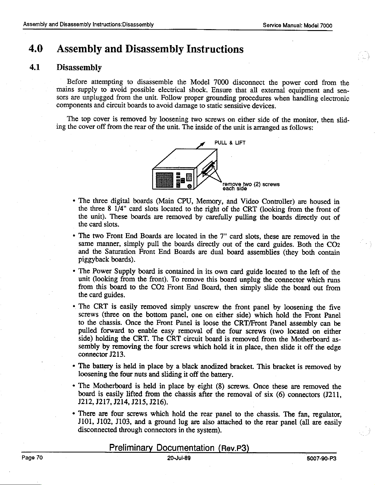
Assembly
and
Disassembly
Instructions:Disassembly
Service
Manual:
Model
7000
4.0
4.1
Assembly
Disassembly
Before
mains
sors
are
components
The
ing
the
*
attempting
supply
unplugged
and
top
cover
cover
off
The
three
the
three 8 1/4"
the unit).
the
card
and
to
avoid
from
circuit
is
from
digital
These
slots.
Disassembly
to
disassemble
possible
the
boards
removed
the
rear
boards
card
boards
electrical
unit.
Follow
to
avoid
by
loosening
of
the
(Main
slots
loçated
are
unit.
removed
Instructions
the
Model
shock.
proper
damage
two
The
inside
7000
Ensure
grounding
to
static
screws
of
PULL & LIFT
CPU,
Memory,
to
the
by
right
carefully
disconnect
that
procedures
sensitive
on
either
the
unit
is
remove
each
of
Side
and
the
pulling
two
Video
CRT
the
all-
external
when
devices.
side
of
arranged
(2)
screws
@)
Controller)
(looking
the
boards
power
equipment
handling
the
monitor,
as
follows:
are
from
directly
cord
electronic
then
housed
the
front
out
from
and
in
of
of
the
sen-
slid-
*
The
two
Front
same
manner,
and
the
Saturation
piggyback
*
The
Power
unit
(looking
from
this
the
card
guides.
*
The
CRT
screws
to
pulled
side)
sembly
connector
*
The
loosening
*
The
board
1212,
*
There
(three
the
chassis.
forward
holding
by
J213.
battery
the
Motherboard
is
easily
1211, 1214,
are
J101, J102,
disconnected
End
Boards
simply
boards).
Supply
from
board
is
easily
on
Once
to
the
removing
is
held
four
lifted
four
screws
Front
board
the
to
the
removed
the
the
enable
CRT.
the
in
nuts
is
held
1215,
pull
the
End
is
front).
CO2
bottom
Front Panel
easy
The
four
place
and
sliding
in
from
the
1216).
which
J103, and a ground
through
connectors
are
located
boards
Boards
contained
To
remove
Front
End
simply
panel,
one
unscrew
is
removal
CRT
circuit
screws
which
by a black
it
off the
place
by
chassis
hold
the
lug
are
in
the
in
the 7"
directly
are
in
Board,
dual
its
own
this
out
board
then
the
on
either
loose
the
of
the
board
is
hold
anodized
battery.
eight
(8)
after
the
rear
panel
also
attached
system).
card
slots,
of
the
board
card
unplug
assemblies
guide
simply
front
side)
CRT/Front
four
screws
removed
it
in
place,
bracket.
screws.
removal
to
the
to
these
card
located
the
slide
panel
which
Panel
(two
from
then
This
Once
of
six
chassis.
the
rear
are
removed
guides.
connector
by
hold
Both
(they
to
the
the
board
loosening
the
assembly
located
the
Motherboard
slide
it
bracket
these
(6)
is
are
connectors
The
fan,
panel
(all
in
the
both
contain
left
of
which
out
the
Front
Panel
can
on either
off
the
removed
removed
(J211,
regulator,
are
easily
the
CO2
the
runs
from
five
be
as-
edge
by
the
Page
70
Preliminary
Documentation
20-Jul-89
(Rev.P3)
5007-90-P3
Page 75

Service
Manual:
Model
7000
Assembly
and
Disassembly
Instructions:Assembly
Diagram
2421-01
(2407-01)
2418-01(
2409-01)CO2
2267-01
2268-01
CO2
Sa02
FE
Sa02 F E
Assembly
2404-01
CONTROLLER
F E
F
E
Diagram
VIDEO
2403-01
4977-13
MAIN
BOARD
TOP
COVER
CPU
2405/61
SIMMS
BOARDS
-01
CPI
AS
BD.
4959.01
RECEPTACLE
2401-01
POWER
BOARD
o
SUPPLY
4998-01
SENSOR
CO2
Я
CAL
ASSY
INPUT
4999-01
る
[Of]
OT
HARNESS
MEMBRANE
© 위
LI]
KEYPANEL
ASSY
211628
6PIN
CONN:
210049
POWER
4985-10
TRANSFORMER
SUPPLY
5016-01
5021-01
5022-01
BATT
MODULE
X
5017-01
FAN
SPEAKER
BATT
CONN
CONN
アン
286210
HARNESS
ASSY
(+)
(-)
05
REGULATOR
215017
TOS
SELF
ASSY
5013-01
REGULATOR
IC
INSULATOR
TAP
SCREW
5055-01
REAR
HARNESS
Cla
5061-01
PANEL
ASSY.
5074-10
FAN
ASSY
RIBBON
CABLE
HARNESS
5007-90-P3
Preliminary
Documentation
20-Jul-89
(Rev.P3)
Page
71
Page 76
Assembly
and
Disassembly
Instructions:Assembly
Service
Manual:
Model
7000
4.2
Assembly
The
assembly
power
is
removed
*
Before
rear
Ensure
»
The
place.
*
The
of
the
from
reinstalling
panel,
battery can
following
one
the
Motherboard
-
Six
(6)
the
-
The
-
The
-
Aluminum
tied
-
The
-
The
into
Model
the
from
be
connections
(6)
pin
speaker
connector
connector
to
connector
connector from
7000
unit
before
the
Motherboard
the
is
replaced
pin
connector
receptacle
plugs
ribbon
one
of
J216.
is
simply
attempting
power
securely
are
from
from
the
by
to
into
screws
from
entry
simply
be
marked
the
J102-103
strap
the
the
the
check
module)
set
in
place
replacing
plugged
from
J212,
the
two
rear
panel
from
which
Cal
Cell
CO2
disassembly
to
assemble
that
the
are
by
eight
the
into
the
the
transformer/battery/fan
and
pin
housing
mounted
on
the
rear
the
front
hold
the
into
J215.
(black)
receptacle
in
it.
two
grounds
securely
(8)
screws.
bracket
Motherboard:
the
two
marked
regulator
panel
into
panel
Motherboard
reverse.
(one
screwed
which
pin
connector
as
J212.
into
J211.
assembly
down.
on
the
Ensure
from
in
place.
holds
into
the
J217.
should
front
that
the
it
in
six
from
be
panel
all
+
+
+
*
*
Whenever
ified
personnel
for
Safety
-
Re-install
front
screws
back
Slide
panel
that
in
place
the
the
Power
components
The
digital
only one
required
the
unit)
The
low
rightmost
ceptacle
The
screws
way
that the
because
CO2
Front
enough
slot.
is
plugged
cover
simply
on
either
the
monitor
to
Checks
instructions.
The
ribbon
CRT
board
assembly,
hold
the
at
this
time.
Supply
on
the
board
boards
into
Memory
of
End
can
each
the
Board
clearance
Verify
into
slides
side.
is
ensure
the
cable
from
the
and
screw
be
sure
to
CRT
in
place.
Board
be
of
clearance necessary
in
face
the
installed
the
connectors,
board
should
for
the
Saturation
that
the
connector
the
SaO2
on
from
disassembled
integrity
in
attach
The
place,
inside
at
be
placed
go
into
Front
the
rear
all
of the
front
panel
place.
the
Front
the
of
the
this
point.
however
in
for
the
Front
from
End
Board.
of
safety
unit.
assembly
Then
black
Panel
64
pin
unit.
The
the
leftmost
the
two
leftmost
End
the
the
unit
checks
Refer
into
re-attach
ground
assembly
connector
the
Board
green
and
should
to
wire
is
boards
order
slot
SIMMS
7"
card
to
SaO2
is
secured
be
the
Operational
J214.
the
CRT
to
one
may
be
polarized
can
be
plugged
is
irrelevant.
(from
the
boards.
slot,
this
be
placed
front
via
performed
to
the
of
the
screwed
so
the
It
front
will
in
the
panel
the
four
by
Tests
section
in
is
of
al-
re-
qual-
Page
72
Preliminary
Documentation
20-Jul-89
(Rev.P3)
5007-90-P3
Page 77
Service
Manual:
Model
7000
Specifications:General
5.0
5.1
5.2
.
.
Specifications
General
Below
vametrix
These
Purposes
change
The
*
Sensor
*
Principle
*
Measurement
*
Accuracy
*
Stability
*
Sensor
*
Weight
.
*
Airway
*
Sensor
are
the
SaO2/ETCO2
specifications
only.
The
without
specifications
notice.
Capnostat™
Type
"On-airway"
nt
of
NDIR,
moving
0-99
040
40-100
m
+2
mmHg
and
durable,
ultra-flexible
of
Sensor
less
less
Connector
Adapter
Disposable
Scc
meets
.
Size
13/4" x 1
cable
.
Operation
dual
wavelength
parts
Range
mmHe
mmHg,
mmHg,
(at
Adapter
glass
and
than
1
oz.
than
6
oz.
or
dead
space,
ANSI
Z-79
1/2" x 3/4";
specifications
Monitor
are
listed
Sensor
(mainstream)
CO2
+2
mmHg
15%
zero, 8 hour
Construction
filled
ABS,
cable
Adapter
without
with
cable
reusable,
for
ratioing,
of
reading
period)
cable
and
less
12
foot
for
the
Model
informational
are
system
than
No-
7000.
subject
no
to
5.3
Oxygen
*
Range
*
Accuracy
*
Resolution
*
Display
*
Audible
+
Alert
Limits
*
Pulse
Rate
*
Pulse
Rate
*
Pulse
Rate
*
Pulse
Rate
*
Pulse
Rate
displayed
*
Pulse
Rate
Saturation
0-100%
100-80%
85-50%
50-0%,
Averaging
Menu
Trend
Tone
displayed
High
Low
30-250
+
1
Menu
Tone
High
Low
+2%
13%
unspecified
°
selectable,
Feature
of
audible
9
ot
Ti
limit;
limit;
Range
beats
Accuracy
1%
of
full
Resolution
beat
per
minute
Display
selectable,
Audible
of
audible
SaO2
value,
Alert
Limits
limit,
limit,
SaO2
of
reading
of
reading
Time
2,
pulse
P
SaQ2
value.
5-100%
0-95%
per
minute
scale
Averaging
2,
Trend
Feature
pulse
35-250
beats
30-245
beats
4,
8,
varies
4,
8,
Sensor
16
Time
16
varies
per
per
seconds
with
seconds
with
minute
minute
5007-90-P3
©
Moisture
*
Shock
*
Step
+
Warm
Resistant
Sensor
Resistant
Sensor
tile
floor
Response
less
than
Up
Time
less
than
sealed
against
moisture
will
withstand
Time
100
milli-seconds
five
(5)
6-ft.
minutes
Preliminary
drop
to
Documentation
20-Jul-89
(Rev.P3)
Page
73
Page 78
Specifications:
The
Monitor
Service
Manual:
Model
7000
5.4
The
Monitor
*
Display
-inch
0-100,
*
CO?
Display
0-50
0-100
*
Respiratory
+1
0-150
+
Respiratory
fixed
*
Calibration
Zero
or
N20/O2
No
operator
Barometric
No
operator
Alert
Limits
Operator
menu
End
Respiratory
Respiratory
30
Visible
Audible
after
* 2 Minute
When
deactivates
for
illuminated 2 MIN
diag.
CRT
0-50
menu
Resolution
scale,
0.25
scale,
0.50
Rate
Resolution
breath
per
minute
respiration/minute
Interval
external
user
at
5%
Detection
at
30
seconds
and
Span
sealed
selectable
or
10%
calibration
Compensation
more
than 2 mmHg
selectable
Pressure
more
Compensation
than 2 mmHg
selectable
selectable
selectable)
Tidal
CO2:
Rate:
Interval
seconds
alert
is
immediate
alarm
violation
occurs
of
Silence
AUDIO
key
audible
two
minutes.
selectable
mmHg
mmHg
Period
gas
cells
COz
flowing
error,
error,
(Automatic
low
and
high
low
and
Delay:
:
10
sec.
set
limit.
is
pressed,
alerts
Indicated
LED.
scale
with
high
by
gas
or
*
Analog
*
Trend
*
Operating
+
Monitor
+
Monitor
*
Power
+
Fuse
*
Battery
(Recorder)
Provides
strip
Respiratory
CO2
CO2
Pulse
Sa02
Plethysmogram
Data
analog
chart
applications
Rate
Value,
Waveform,
value,
value"
Output
output
for
Value,
waveform
Memory
Menu
selectable
times
of;
20
minutes, 1 hour, 4 hours, 8 hours.
trending
memory
Environment
10-40° C (50-104°
0-90%
relative
(non-condensing)
F)
humidity
Size
Height:
5.5
Width:
Depth:
in.(13.97
13.9
in.(35.24
13.4
in.(33.97
cm)
cm)
cm)
Weight
21
pounds
100/120/220/240
50/60
(must
(9.53
Hz
be
specified
kg)
vac
at
110%,
time
Rating
U.S.
Specification, 2 ampere
slow-blow
European
250V
Type,
Battery
Recharge
recharged
Specification, 1 ampere
(x2)
lead-acid
gel-cell
Life, 1 hour
time,
battery
fully
in 8 hours
max.
external
of
order)
Page
74
*
Audio
+
Digital
Off
Press
and
hold
seconds,
audible
will
alerts.
illuminated
Data
Output
Provides
compatible
RS232C
RS232
computer
AUDIO
key
for
deactivate
Indicated
OFF
with;
LED.
data
by
output
interface
Preliminary
3
5.5
Documentation
20-Jul-89
Options*
*
Sampling
Attachment
Allows
bated
*
Neonatal
Adapter
less
© * -
scheduled
1988
(Rev.P3)
gas
sampling
patient
than 1 cc
for
release
for
non-intu
applications
dead
space
in
the
summer
of
5007-90-P3
Page 79
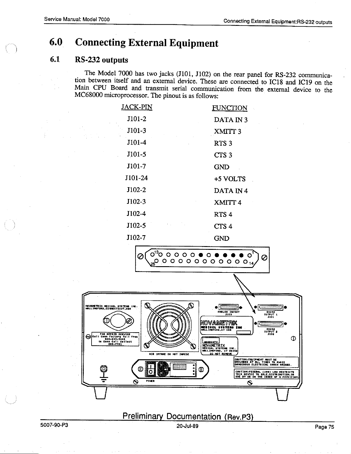
Service
Manual:
Model
7000
Connecting
External
Equipment:RS-232
outputs
6.0
6.1
Connecting
RS-232
The
tion
Main
MC68000
outputs
Model
between
CPU
itself
Board
microprocessor.
7000
External
has
two
and
an
and
transmit
The
JACK-PIN
J101-2
J101-3
J101-4
J101-5
J101-7
J101-24
1102-2
J102-3
Equipment
jacks
(J101,
external
serial
pinout
J102)
device.
is
These
communication
as
follows:
on
the
rear
are
connected
from
FUNCTION
DATA
XMITT
RTS
CTS
IN
3
3
3
GND
+5
VOLTS
DATA
XMITT
IN
4
panel
3
4
for
to
the
RS-232
IC18
and
external
communica-
IC19
device
on
to
the
the
το.
WALL
INGPORD,
TOR
jean
conn
An
т]
J102-4
J102-5
J102-7
CONNECTICUT,
@(
REPRIE
800-203-5444
conn
USA
70
SERVICE
ractory
Toit
collect
Cali
245-7701
RTS
4
CTS
4
GND
0[0000000000000
200000000000:
=>"
ㆍ
AMALOG
OOVAMETW
[ce
MALL
rree
WALL
STEVENS
ING/GRO,CT
TRIX
NOVAME
SYSTEME
PEOICAL
ENGPORD,
°
INFOUT
2103
tne
USA
INC.
04452]
CT
CAUTION1EQUIPMENT
GROUNDED
DANGEROUS
SAUTION:FEDERAL
THIS
DEVICE
USE
BY
İrez.
AT
ALL
ELECTRICAL
TO
OR
OM
THE
S
の
0023
OUTPUT
3101
mm
te
dos
MUST
BE
TIMES
TO
SHOCK
(USA)
LAM
SALE,
OISTRIOUTION,
ORDER
OF A PHYSICIAN,
O
1
AVOIO
HAZARD.
RESTRICTS
©
OR
/
5007-90-P3
Preliminary
Documentation
20-Jul-89
(Rev.P3)
Page
75
Page 80

Connecting
External
Equipment:Analog
In
/
Out
Service
Manual:
Model
7000
6.2
Analog
6.2.1
future
panel
+10
6.2.2
er
located
lows:
Analog
The
software
of the
volts
Analog
The
can
assign
In / Out
In
Analog
monitor.
then
digitize
Output
Analog
to
on
J103
CHANNEL
Input
on
release
It
them
Output
one
of
on
the
CHI
CH2
CHB
GROUND
the
Model
the
inputs
will
to
of
the
six
parameters
rear
panel
7000
will
consist
be
processed
Model
and
be
of
three
7000
through
is
is
not
enabled
enabled
channels
by
the
consists
the
labeled
J103
through
and
utilized
that
MC68000
of
three
front
“ANALOG
PIN
2
10
9
3&11
the
current
through
can
take
microprocessor.
output
panel
softkeys.
IN/OUT”.
J103
an
analog
channels
The
#
software.
on
voltage
which
The
outputs
pinout
the
is
In
the
as
a
rear
of
us-
are
fol-
NOVAMETRIX
WALL
MEDICAL
INGFORO,
FOR
lean:
Cano
SYETENS
CONNECTICUT
REPAIR
TERTIET
Par
(REIN
Vi
INC,
USA
ere
ooooeeo
RIT
\
654
SYSTEMS
FORD
CT
USA
NOVAMETRIX
MEDICAL
IVETE
MALLINGPORD,
CT
INC.
06482]
[CAUTEON:
106
EQUIPMENT
GROUNDED
AT
DEVICE
BY
OR
S
ALL
ELECTRICAL
TO
SALE
ON
THE
DANGEROUS
CAUTIONIFEDERAL
THIS
USE
MUST
BE
TIMES
TO
AVOID
3HOCK
CUSA)
LAW
DISTRIBUTION,
ORDER
OF R PHYSICIAN.
U
HAZARD.
RESTRICTS
OR
/
Page
76
Preliminary
Documentation
20-Jul-89
(Rev.P3)
5007-90-P3
Page 81

Service
Manual:
Model
7000
Connecting
External
Equipment:Analog
In
/
Out
These
type
of
Analog
5
volts.
The
when
‘key
until
*
Press
*
Select
channels
output
will
Converter
The
scale
PARAMETER
Capnogram
End
Tidal
Resp.
Plethysmogram
Saturation
Pulse
voltages
in
the
“ANALOG
the
desired
System
Setup
Control
from
can
depend
(DAC)
for
Rate
Rate
at
scale
the
be
assigned
on
used
each
of
these
outputs
CALIBRATION
is
reached.
from
the
“CONTROL
the
specific
for
these
the
parameters
0-100
0-100
0-200
0-100
0-100
0-250
can
real-time
MENU”.
to
any
outputs
RANGE
mmHg
mmHg
br/min
be
MENU”
To
get
display
one
of
six
assignment
can
produce
is
broken
measured
to
the
by
simply
“ANALOG
down
(waveform
parameters
of
the
channel,
an
as
follows:
OUTPUT
0-3.92
0-1.96
0-3.92
0-2.49
0-1.96
0-4.96
at
volts
volts
volts
volts
volts
volts
ZERO, HALF,
pressing
CALIBRATION
or
digital).
in
the
analog
SCALE
(19.6
(19.6
(19.6
maximum
(19.6
(19.6
the
Model
the
voltage
mv/0.5
7000.
8-bit
mmHg)
Digital
from
mv/mmHg)
mv/br/min)
output
mv/%
)
mv/bts/min)
and
FULL
Toggle
Scale
MENU”
The
to
0
to
scale
soft-
*
Press
dow
ready
different
Interfaces,
appears
been
A
more
explained
the
backed
in
up
ered
press
assigned,
channels).
in
depth
in
the
Operators
up
memory
default
the
then
Analog
Calibrate
if
not
discussion
lose
mode.
Output
Channels
then
on
Manual.
power
or
softkeys.
press
Select
setting
The
unit
be
replaced,
(this
the
channels
will
When
assumes
Channels
up
select
the
same
the
that
to
for
the
“ANALOG
the
assign
the
different
default
will
occur
OUTPUT”
channels
parameters
parameters
assignments
if
the
have
to
unit
win-
al-
the
should
is
pow-
is
5007-90-P3
Preliminary
Documentation
20-Jul-89
(Rev.P3)
Page
77
Page 82

Troubleshooting
Guide:Error
Messages
:
Service
Manual:
Modei
7000
7.0
7.1
Troubleshooting
Error
message
Sensor
Sensor
Sensor
Probe
Check
Messages
If a sensor
on
Not
Unplugged
Over-Temp..............
Faulty
Airway
related
the
display
Calibrated
.....................,..
eee
error
screen.
...............
Guide
condition
The
........
Sensor
Sensor
Sensor
Sensor
Sensor
Monitor
Note:
sensor
monitor
Sensor
Monitor
Sensor
Sensor
Optical
are
airway
Calibration
Calibration
Tf
doing
Sensor
Monitor
is
detected,
error
messages
has
not
has
been
not
connected
or
sensor
faulty—do
faulty—do
This
message
connected).
and
sensor
faulty—do
faulty—do
not
up
not
connected
path
blockage—check
not
contaminated,
adapter
error—tetry
cell
gas
calibration—CO2
faulty—do
faulty—do
the
Model
are
listed
been
calibrated—calibrate
disconnected
to
cable
faulty—replace
not
use,
not
may
The
message
warm
not
use,
not
to
temperature—wait
to
check
error—try
then
monitor—connect
replace
use,
contact
be
displayed
up
(approximately
replace
use,
contact
airway
sensor
calibration
gas
concentration
not
use,
replace
not
use,
contact
7000
will
display
below.
reconnected—recalibrate
sensor
sensor
sensor
qualified
at
should
sensor
qualified
until
adapter
that
airway
is
properly
calibration
sensor
qualified
personnel
power-up
disappear
30
seconds).
personnel
sensor
or
warms
cal
cells
adapter
seated
too
high
personnel
(with
as
windows
an
the
on
error
up
the
Page
78
Reference
Not
up
to
Zero
Cal
Error
Temp
Error
..................
Sensor
Optical
are
not
airway
not
path
contaminated,
adapter
Calibration
Calibration
If
doing
Sensor
Monitor
Sensor
Monitor
...................
Sensor
Sensor
Monitor
....................
Calibration
Optical
Preliminary
gas
faulty—do
faulty—do
faulty—do
faulty—do
not
faulty—do
faulty—do
contamination—clean
Documentation
20-Jul-89
up
to
temperature—wait
blockage—check
check
error—retry
cell
error—try
calibration
gas
calibration—CO2
not
use,
replace
not
use,
not
use,
replace
not
use,
up
to
temperature—wait
not
use,
replace
not
use,
error—retry
calibration
(Rev.P3)
until
sensor
that
airway
sensor
is
properly
calibration
concentration
sensor
contact
qualified
sensor
contact
qualified
until
sensor
sensor
contact
Zero
qualified
Cell
and
warms
adapter
seated
too
high
personnel
personnel
warms
personnel
sensor
up
windows
on
the
.
up
windows
5007-90-P3
Page 83

Service
Manual:
Model.z000
Zero
Cell
failure—contact
If
gas
cal,
Zero
Cal
cal
contamination—clean
dows
Sensor
faulty
—replace
gualified
attempted
airway
sensor
Troubleshooting
personnel
while
COz
is
adapter
and
Guide:Error
(use
gas
present
or
sensor
Messages
cal)
opti-
win-
Calibration
Optical
Span
Span
If
cal
dows
Sensor
Data
Transfer
SyncError...........................
Probe
Probe
one
lem
Error
Error
The
following
might
diagnostic
*
Minor
*
Major
*
Incorrect
Error
2.......................
4.......................
encounter
listing
component
component
...........
section
when
but
setup,
i.e.
Monitor
Monitor
Red
obstructing
Sensor
Infra-red
light
Sensor
is
intended
operating
will
help
failure,
failure,
wrong
contamination—clean
cell
value
Cell
gas
cal,
contamination—clean
faulty—replace
faulty—do
faulty—do
LED
faulty
LED
obstruction.
faulty—replace
the
in
determining
i.e.
battery,
i.e.
internal
mains
error—retry
on
failure—contact
Zero
Cal
on
SaO2
path.
light
—replace
on
SaO2
to
help
Model
fuse.
electronics.
fuse
setting.
calibration
cell
matches
attempted
sensor
not
use,
not
use,
sensor
sensor.
sensor
sensor.
determine
7000.
whether
Span
Cell
and
value
set
in
qualified
while
airway
contact
contact
nonfunctional—
It
is
the
personnel
ČO2
is
adapter
nonfunctional—-check
the
possible
by
no
problem
and
qualified
qualified
check
means
is:
sensor
software?
present
personnel
personnel
cause
windows
(use
gas
or
sensor
for
object
of
a
complete
opti-
'
cal)
win-
for
problems
prob-
5007-90-P3
*
verify
rear
illuminated
*
check
*
check
*
power
shipping
*
wrong
*
Sensor
the
line
panel
the
is
fuse
battery
supply
damage).
mains
loading
(assuming
“connected.
Preliminary
cord
in
the
|
inside
the
voltage,
board
voltage
(or
setting,
down
is
attached
position
no
battery
power
other
and
and
backup).
entry
board)
check
the
power
supply,
Documentation
20-Jul-89
undamaged,
the
green
block
jarred
power
entry
try
“AC”
where
the
loose
from
module.
powering
me
(Rev.P3)
mains
LED
line
its
up
power
on
cord
card
with
switch
the
front
is
attached.
holder
the
sensors
on
the
panel
is
(possible
dis-
_
O
Page
79
Page 84

„Troubleshooting
Guide:Error
Messages
Service
Manual:
Model
7000
NOTE:
time
contact
-Unit
-CRT
-Monitor
-Unit
If
the
Novametrix
intermittently
*
unit
is
running
tery
voltage
jitter,
unsteadiness,
+
battery
¢
CRT
¢
external
voltage
requires
electromagnetic
will
+
CPU
lockup,
will
not
+
unit
is
programmed
*
Zero
cell
switch
*。
Capnostat™
unit
continually
Service
turns
on
is
dropping
low
alignment.
not
respond
try
powering
calibrate
is
CO2
sensor
blows
Dept.
off
by
itself,
battery
power
below
or
battery
interference.
to
button
down
when
sensor
to
calibrate with
defective,
not
properly
fuses
when
for
assistance.
(or
AC
its
threshold
is
disconnected
or
softkey
then
powering
is
placed
gas.
fitted
powered
power
level,
(or
dead).
commands,
up
into
ZERO
into
ZERO
on
or
was
interrupted),
again.
cell,
cell
slot.
when
on
for a period
and
the
of
bat-
Page
80
Preliminary
.
Documentation
20-Jul-89
(Rev.P3)
5007-90-P3
 Loading...