

Page 1

HAND-HELD
CAPNOGRAPHY MONITOR
Service Manual
Model 610
April 17, 2000
Catalog No. 6700-90-01
Novametrix Medical Systems Inc.
PO Box 690
5 Technology Drive
Wallingford, Connecticut, U.S.A. 06492
Page 2

Page 3

Contents
Safety ..................................................................................................... 1
Introduction ........................................................................................... 3
Indication for use ..................................................................................3
Operational Overview ........................................................................... 3
Configuration Menu ...................................................................... 4
Theory of Operati on ............... ............. ............ .................................... .7
2738 Main Board ..................................................................................7
System Memory ............. .................................... ........................10
Serial Communications .............................................................. 10
User Interface Control Circuitry ..................................................11
Real Time Clock, Power on RESET Generation and Glue Logic .......12
CO2 System Analog Subsections ......................................................12
CO2 Pulser Source Drive ................................. ............ .............. 12
Capnostat Case and Detector Heater Control ...................................14
CO2 Input Signal Path ....................................................... .. .. ....... .... .15
Capnostat Interface ............................................................................ 15
Barometric Pr e ssure Circuitry .......................... ............ ............. .15
Power Supply and Battery Charger .................................................... 16
2737 Board ................................................................................ 17
Functional Tes ts ....................................................... .......................... 19
Equipment Required ..........................................................................19
Procedure ...........................................................................................19
Accuracy Tests ............................. ....... .. .. .. .... .. .. ....... .. .. .... .. .. .. ....... .. .. .21
Equipment Required ..........................................................................21
Test Procedure .................................................... ..................... .......... 21
Electronic Tes ts .................... ............. ............ ............. ........................25
Equipment Required ..........................................................................25
Test Procedure .................................................... ..................... .......... 25
Safety Testing .......................... ............. ............ ............. ....................28
Maintenance ........................................................................................ 29
General ............................................................................................ .29
Maintenance Schedules ..................................................................... 29
Cleaning and Sterilization .......... ..................................................... ... 30
Monitor ....................................................................................... 30
CAPNOSTAT CO
Sensor .........................................................30
2
Single Patient Use Airway Adapters ..........................................30
Battery and AC Oper a tio n ..................... ............ ............. ............. .......30
Rev. 00
M610 Service Manual
iii
Page 4

Battery Indicator ........... ............. ................................... .............. 31
Rechargeable Batteries .............................................................31
AA Lithium Batt e ries ............... ............ .................................... ...32
AC wall adapter/charger (External DC supply) ..........................32
Removing and installing the battery ...........................................33
Assembly Exchanges ......................................................................... 33
Disassembling the Monitor .........................................................33
Reassembling the mon i to r .................... ............. ............ ............36
Serial Communications/Power Interface Connector .......................... 36
Software Update In structions .............. ............ ............. ............. .........37
Equipment Required .................................................................. 3 7
Setup ..........................................................................................37
Procedure ..................................................................................37
Display Status Messages ....... .. .... ..... .... .. .. .. .... .. ..... .... .. .. .. .... .. ....... .. .. .39
System Messages ...................................................................... 39
Battery Status and Alerts ...................................................................41
Status Messages and Codes .....................................................41
Specifications .....................................................................................43
Monitor Spec ifications ........................... ............ ............. ............. .......43
Physical ...................................................................................... 43
Monitor and CAPNOSTAT
CO2 Sensor .....................................43
Symbol Descrip tio n s ........ ............. .................................... .........44
Accessories .........................................................................................45
Parts ..................................................................................................... 47
Drawings and Sche matics ..... ............. ...............................................55
Rev. 00
M610 Service Manual
iv
Page 5

Guarantee
Equipment manufactured or distributed by Novametrix Medical Systems Inc., is fully guaranteed,
covering materials and workmanship, for a period of one year from the date of shipment, except for
certain dispo sable pr oducts and products wit h stated gu arantees other than one year. Nov ametr ix reserv es
the right to per form gu ara ntee s ervi ce(s) at it s f actor y, at an aut horiz ed rep air s tati on, o r at t he cus tome r’s
installation.
Novametrix’ obligations under this guarantee are limited to repairs, or at Novametrix’ option,
replacement of any defective parts of our equipment, except fuses, b atteries, and calibration gasses,
without charge, if said defects occur during normal service.
Claims fo r damage s durin g shipme nt must be filed pro mptly wi th the tr ansportati on compa ny. All
correspond ence co ncerning the equipme nt mu st sp eci fy both the model na me and number, and the serial
number as it appears on the equipment.
Improper use, mishandling, tampering with, or operation of the equipment without following specific
operating instructions will void this guarantee and release Novametrix from any further guarantee
obligations.
Service Department
For factory repair service, call toll free
1-800-243-3444
In Connecticut, call Col lect (2 03) 265-7701
(203) 284-0753
FAX
http://www.novametrix.com
techline@novametrix.com
Email
Caution:
license d medical practitioner.
Copyright 1998, 2000 Novametrix Medical Systems Inc. This document contains information which
is proprietary and the property of Novametrix Medical Systems Inc., and may not be reproduced, stored
in a retrieval system, translated, transcribed, or transmitted, in any form, or by any means, without prior
explicit written permission f rom Novametrix Medical Systems Inc.
Novam etrix res er ves the right to change spe cif icat ions wit hou t notic e. TID AL WAVE is a trademark and
CAPNOSTAT is a registered trademark of Novametrix Medical Systems Inc.
Federal (U.S.A.) law restricts this device to sale, distribution, or use by or on the order of a
Declaration of Conformity with European Union Directive
The Authorized Representative for Novametrix equipment is:
D.R.M. Green
European Compliance Services Limited
Oakdene House
Oak Road
Watchfield
Swindon, Wilts SN6 8TD
Rev. 01 Model 610 Service Manual
v
Page 6

Revision History
00 Release 23-Mar-00
01 R-N746 17-Apr-00
Service Policy
Novametrix Medical Systems Inc. will provide Warranty Service Support to its customers within 48
hours of receiving a telephone request for technical support. This 48 hour period begins once a service
request is placed through the Factory Technical Support Department in Wallingford, Connecticut.
Novametrix provides factory direct technical support to its customers through a technical support group
located in Wallingford, Connecticut and company service representatives located throughout the United
States. All Technical Support for Novametrix products is provided “Factory Direct”.
Novametrix provides 24 hour a day technical support accessibility via telephone numbers (800) 2433444 or (203) 265-7701. After hours technical support requests (before 8:00 AM and after 5:00 PM
Eastern Time) will be resp onde d to promptly by the Technical Support On-Call st aff. It is suggest ed t ha t
any person calling in for technical support have the inoperative equipment available for preliminary
trouble sho o ti ng a s wel l a s p rod u ct id e n tifica tio n. Novam etr ix re ser ves the ri gh t t o re p ai r or r ep l ace any
product found to be defective during the warranty period. Repair may be provided in the form of
replacement exchange parts or accessories, on-site technical repair assistance or complete system
exchanges. Repairs provided due to product abuse or misuse will be considered “non-warranty” and
invoiced at the prevailing service rate. Any replaced defective material is expected to be returned to
Novametrix within 10 days of being provided in order to avoid additional charges. Exchanged material
should be retu rned promptl y and direct ly to Nov ametr ix using the r eturn paper work and shi pping label (s)
provided. Transferring return materials to local sales or dealer representatives does not absolve return
responsibility.
Novametrix manufactures equipment that is generally “user serviceable” and can usually be repaired
with the r eplacement of a plug-in e lectro- mechanical assem bly by the clinic al end user . When repair parts
are provided, the recipient can call into Novametrix for on-line replacement assistance and repair
assurance. In the ev ent a repla cement par t requires increased te chnical cap abilit y , Technical Support may
request Biomedical assistance, provide on-site technical support or complete replacement equipment. If
the customer requ ires the return of th eir original product, the exchange materia l will be considered
“loaner material” and exchanged again after the customer equipment is repaired.
Novametrix promotes customer participation in warranty repairs should they become necessary. This
program all ows f or cus tomer tr aining an d a smoot h trans ition i nto self -maintena nce afte r war ranty , which
can provide substantial cost savings on repairs throughout the product’s life.
The Novametrix Technical Support D epartment can provide technical product support at a level
appropriate to most customers protocol and budget requirements. Please contact the Technical Support
Group at Novametrix for additional information.
Additional Novametrix Technical Support Programs
• Focus Series Technical Training Seminars
• Test Equipmen t and Test Kits
• Service Contract / Part Insurance Plans
• On-Site Technical Support
• 24 hr. telephone support
• “Demand Services”
Flat rate parts-exchange,
Flat rate return for repair
Time and Material,
Full warranty, discounted replacement sensors
Model 610 Service Manual Rev. 01
vi
Page 7

Section 1
Safety
The
TIDALWAVE
instrument to ground is limited to less than 100 uA.
For maximum patient and operator safety, you must follow the following warnings and cautions.
handneld capnograph is electrically isolated. Patient leakage current flowing from the
WARNINGS
!
Explosion Hazard:
•
instrument in such an environment may present an explosion hazard.
Electrical Shock Hazard:
•
source before cleaning it. Do NOT use a damaged sensor or one with a damaged cable. Refer
servicing to qualified service personnel.
Failure of Operatio n:
•
has been corrected by qualified personnel.
• Do not operate the monitor if it appears to have been damaged.
• Never sterilize o r immerse the monit or in liquids.
• The monitor does not alert for NO RESPIRATION if the airway adapter is removed from the
CAPNOSTAT CO
• Do not position the CAPNOSTAT CO
strangulation.
• Use the external battery charger in non-patient areas o nly.
• Do not apply tension to the sensor cable.
Indicates a potentially harmful condition that can lead to personal injury.
Do NOT use the moni tor in the presence of flammable anesthetics. Use of this
Always turn the monitor off and disconnect the external DC power
If the monitor fails to respond as described, do not use it until the situation
sensor.
2
sensor’s cable in a manner that may cau se e n t angl ement or
2
!
• Federal (USA) law restricts this device to sale by or on the order of a licensed medical practitioner.
• Use only a Novametrix approved power supply. Use of any other power supply may damage the
• The Tidal Wave is not intended to be used as a primary diagnostic apnea monitor and/or recording
• Refer servicing to qualified personnel.
• Never sterilize o r immerse the monit or in liquids.
• Do not sterilize or immerse the sensor except as directed in this manual.
• Do not store the monitor or sensors at temperatures below 14° F (-10° C) or above 131° F (55° C).
• Do not operate the monitor or sensor at temperatures below 32° F (0° C) or above 104° F (40° C).
• Where electr omagnetic devic es (i.e., ele ctrocautery) ar e used, patient monitoring may be interrupted
Rev. 01
Indicates a condition that may lead to equipment damage or malfunction.
Tidal Wave and void the warranty.
device.
due to electromagnetic interference. Electromagnetic fields up to 3 V/m will not adversely affect
system performance.
CAUTIONS
Model 610 Service
Manual
1
Page 8

Section 1
NOTES
Indicates points of particular interest or emphasis for more efficient or convenient operation.
• The Tidal Wave monitor is intended for operation with Novametrix Single Patient Use airway
adapters.
• Certain rebreathing circuits, or the presence of artifact such as cardiogenic oscillations, may cause
the monitor to react to non-respiratory CO
affects only the RESP (respiration) numeric values on the display.
• Refer to the User’s Manual (Cat. No. 6700-23) foradditional operational information.
• Operating the TIDAL WAVE below 50° F (10° C) will result in longer warm-up time and reduce
battery life.
• Components of this product and its associated accessories which have patient contact are free of
latex.
fluctua tions as if they were br eaths. This condition
2
2
Model 610 Service
Manual Rev. 01
Page 9
Section 2
g
g
g
g
g
g
g
g
g
Introduction
The TIDAL WAVE hand-held capnograph from Novametrix is designed to monitor CO2 whenever
capnography is required. The monitor combines full graphics capabilities, a no-respiration alert and
rugged CAPNOSTAT CO
sensor technology.
2
2.1 Indication for use
The TID AL WAVE capnograph is a hand-hel d non -i nvasive CO2 monitor spec ifically desi gne d f or short
term monitoring during transport, emergency, anesthesia, post anesthesia recovery, respiratory care and
intensive car e.
2.2 Operational Overview
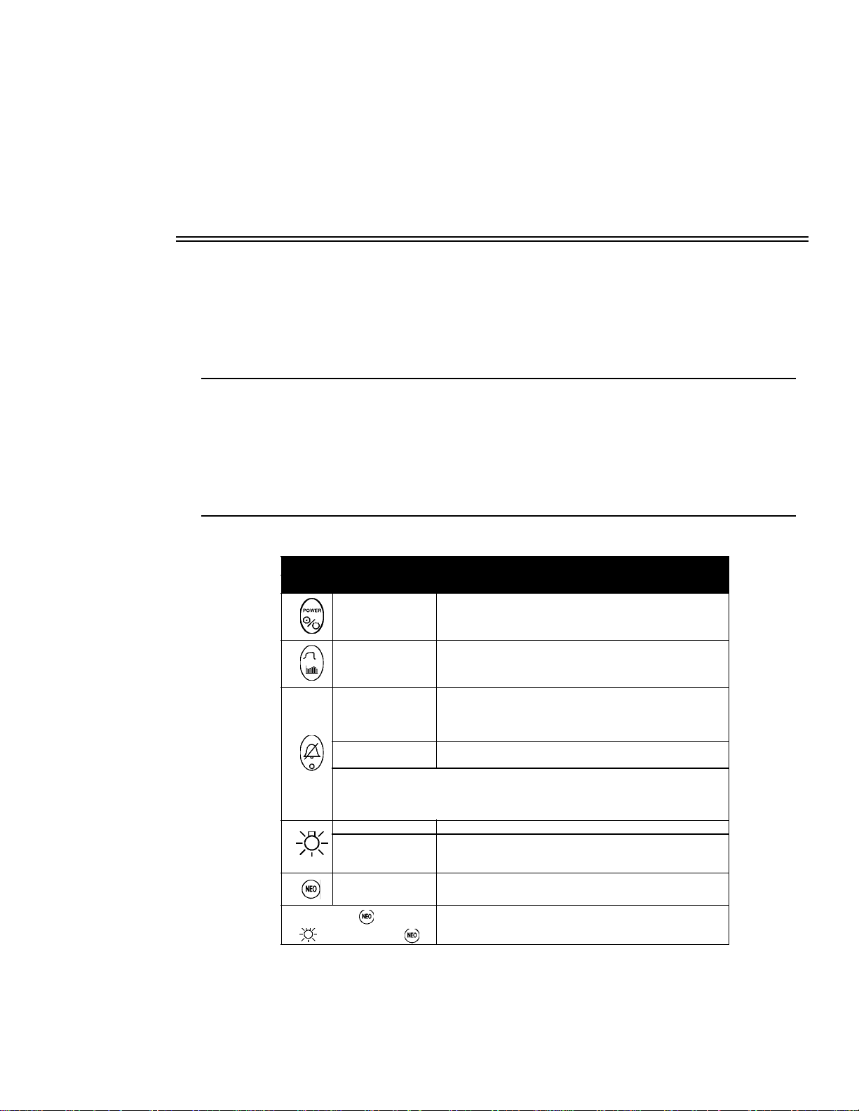
KEYS AND INDICATORS
Key Operator Action Function
1Press
Switches power on/off.
Capnogram available immediately after self test, fully
operational in 60 seconds.
2 Press Selects Capno
Press
3
4
5
Press and hold , then pres s
Press and hold for 2
seconds
NOTE: -Refer to alert indica tor below.
-Key inactive if audio disabled in confi
-The monitor may be factory confi
function (two minut e silence is still availab l e).
Press Sets display back light off/on.
Press and hold
Press , then follow
screen instructions
before releasin
Rev. 01
ram (waveform) or trend di s pl ay .
Silences audi bl e alerts for two minutes. Press a
deactivate. Al so resets (cancels) audio if pressed durin
an active alert (audio will not alert for the duration of the
NO RESPIRATION event that was silenced).
Silences audible alerts until the key is pressed a
held. This function is reset upon the next power-up.
uration menu.
ured as to not allow the audio off
Chan
es contrast/viewing angle of display (changes one
step every second).
e application mode: adult/pediatric or neonatal
Chan
airway adapter use.
Displays CONFIGURATION screen (Select compensation
O and high O2, CO2 scales, etc.).
for N
2
ain to
ain and
Model 610 Service
Manual
3
Page 10
Section 2
g
y
g y
g
y y
g y
g
g
g
y
y
g
y
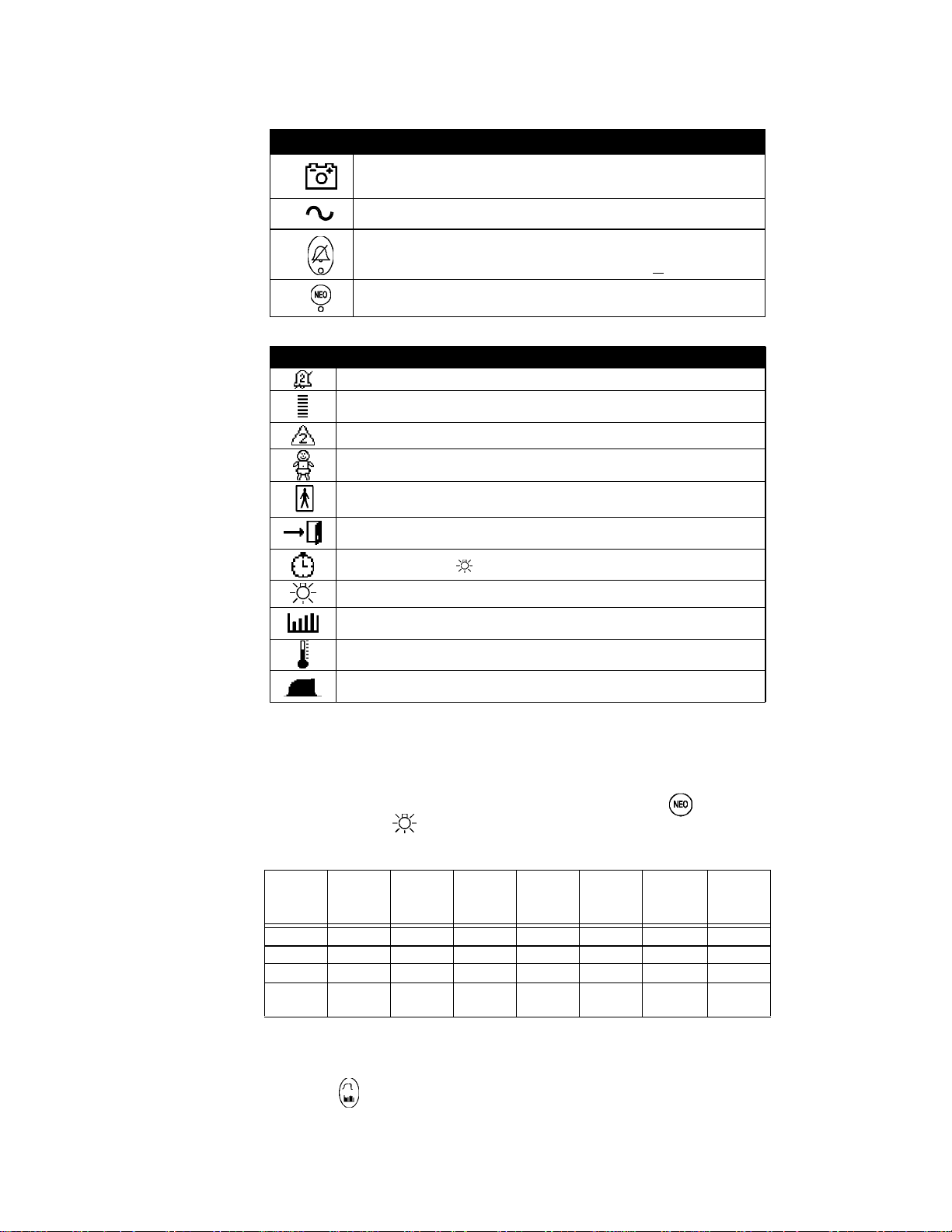
Indicators Function/Meanin
A
B Illuminated when "external" power is connected.
C
D Illumina tes when in NEO mode (see #5 above).
Green; batter
Slow flashin
Fast flashin
Stead
Flashin
Flashin
is fully charged.
ellow; battery power is low.
red; battery is exhausted (10 - 15 minutes monitor time left).
ellow: audio sil enced for 2 min., no alert in progress.
ellow: audio silenced (no alert in progress).
red and yellow: alert in progress; audio is off or 2 minute silence.
Icons Function/Meanin
Audible aler t s ilenced for two minutes.
Breath bar. Gi ves real time indication of breaths.
Status indica tor. Numbers 1-8 indicate speci fic conditions.
Neonatal icon. Used to indicate neonatal mode selected.
Adult icon. Used to indicate pediatric/adult mode selected.
Operational Overview
Exit CONFIGURAT ION or time/date screen.
Set time/date. Press from CONFIGURATION screen to set time/date.
Indicates ba ck l i
Trend screen icon. Displa
Sensor not up to te mperature icon. Displa
zero and the sensor is not at operatin
Breaths detec ted icon. Displa
monitor detect s breaths.
ht key.
ed in Trend screen.
ed when performing an adapter
temperature.
ed when performing an adapter zero and the
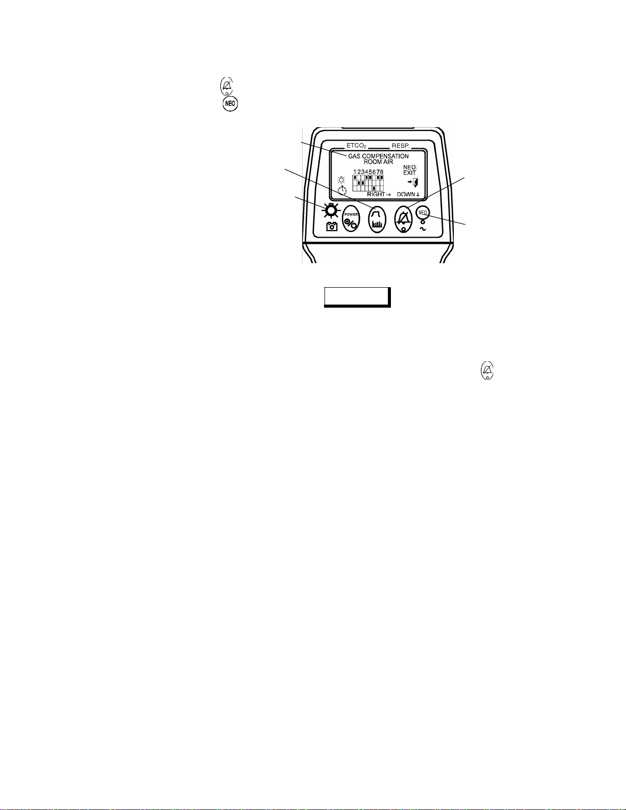
2.2.1 Configuration Menu
A CONFIGURATION menu is provided on the TIDAL WAVE in order to allow customizing of various
settings. To access the CONFIGURA TION menu, pr ess and hold t he NEO key , then , simultaneousl y
press and hold the Backlight key until the CONFIGURATION screen is displayed. The grid on the
screen corresponds to the following chart, which indicates the available selections:
Units
Gas
sation
Compen-
12345678
*Room air
O
>60%
2
N
O >60%
2
balance O
2
Scale
Waveform
Small Slow
*Medium *Medium
Large Fast 60 seconds %
Speed
Waveform
Time
NO RESP
*20 seconds *mmHg
40 seconds kPa *Low Reserved Filled
2
CO
Alert
Volume
Disabled
*High
RS232
Interface
*NovaCOM *Unfilled
--
Fill
Waveform
4
Model 610 Service
*-default settings
Changing CONFIGURATION settings:
Press the Waveform key to select among columns 1 through 8 (Gas comp., Waveform scale, etc.).
Manual Rev. 01
Page 11
Operational Overview
Section 2
Press the Alert key to change the setting of the selected column.
Press the NEO key to exit the CONFIGURATION menu and return to normal monitoring mode
(selections will be saved).
Displays selected setting
Selects column
Press to set time/date
Changes settings of
selected column
Press to exit
NOTE
When formatting, the selected column is described on the first line of the text at the top of the screen. A
flashing, f il le d b ox in dic at es the current settin g. The se tt ing is des cr ibed on the second line of text at t he
top of the screen.
units are attempted to be changed after data has been collected a message warning that trend
If CO
2
memory will be erased is displayed. To change units and erase trends press the key a second time.
Rev. 01
Model 610 Service
Manual
5
Page 12

Section 2
Operational Overview
[This page intentionally blank.]
6
Model 610 Service
Manual Rev. 01
Page 13

Section 3
The TID AL WAVE is a microprocessor -based han dheld i nstru ment th at me asures the cl inic al par amet ers
production and respiration rate. The system contains all the circuitry necessary for displaying
of CO
2
patient information gathered from the CAPNOSTAT® sensor. The theory of operation of the TIDAL
WAVE is explained in detail in the subsections that follow.
3.1 2738 Main Board
For circuit diagrams of the digital section described below, refer to sheet 1 of the Main Board (2738-03)
schematics. Embedded control for the system is provided by IC 1, a Motor ola MC6833 2 integrated
microcontroller. In addition to a full 32-bit Central Processing Unit (CPU), this device also contains
circuitry for system clock gen eration, peri pheral chip sel ect generati on, data control, interrupt gene ration,
a sophisticated timing co-processor, synchronous and asynchronous serial communication. In general,
functional signals are grouped together into por ts , and each signal can be independently programmed by
software to be its pre-defined port function or as discrete I/O. Additionally, the functionality for several
ports (Port C, E and F) can be pre-defined by the state of the data bus on system power-up. A special
“background mode” port allows the device to be controlled by an external source for system debugging
and testing. Also integrated on-chip are several activity monitors, as well as a software watchdog to
ensure proper device and system operation. Refer to Table 1.
Theory of Operation
Table 1. CPU Port Functions
Functionality Control,
Port Defined Function
TPU
16 Channels
QSM
4 Synchronous Serial
Chip Selects & one
asynchronous
serial channel
Background Mode System debugging Allows an appropriate external device to
C Chip Selects D0: CSBOOT* Data Width, 8 or 16-bit
E Bus Control D8: Control Signals or Discrete I/O
F MODCK and Interrupts D9: MODCK & IRQ or Discrete I/O
Timing Signal Generation Each channel independently user
programmable as TPU function or as
Discrete I/O
Serial Communications Port:
QSPI: Queued Serial Peripheral
Interface
SCI: Serial Communications
Interface
QSPI chip selects independe ntly use r programmable, can be used as
Discrete I/O or decoded to create u p to 16
chip selects. SCI transmit can be programmed as Discrete I/O
control the microprocessor and system
D1: CS0*-CS3* or BR*,BG*,BGACK*
D2: CS3*-CS5* or FC0-FC2
D3-D7: CS6*-CS10* or A19-A23
Data Bus Control
(Alt Functions: D pulled low)
Rev. 01
Model 610 Service
Manual
7
Page 14

Section 3
2738 Main Board
The maximum operating frequency of the integrated processor is 16.78 MHz. The operating frequency
is software sel ecta ble and gene rated by an internal VCO operatin g from Y1, a 32.768KHz wat ch crystal .
The Timing Processor Unit (TPU) co-processor of the MC68332 provides timing generation derived
from the system clock. This feature is utilized to control the precise timing required for the acquisition
of the End T idal Ca rbon Dioxid e (etCO
) signals. Th e TPU is also u se to gener ate the PWM (pul se W idth
2
Modulation) control for the CAPNOSTAT case and detector heaters, generate clock output for the LED
backlight, monitor keypanel input, generate the DAC load pulse, as well as provide the frequency
generation for the audio tones. See Table 2.
Table 2. TPU Timing Genera tion for the etCO2 subsystem
Signal Name Function / Timing
CO2AZ Auto Zero Clears the Sample/Hold circuitry prior to data acquisition.
Active High, 90 us
CO2PWENB Pulse Width Enable Defines the active time for both phases of the bipolar source
pulse, used for pulse width protection circuitry.
Active High, 830 us
SRCDRV0 Source Drive 0 First source drive signal.
Active High, 405 us
CS*/H Current Sample/Hold Enables circuitry for source current measurement. Sample is
taken when SRCDRV0 is active.
Low = Sample, 90 us, High = Hold
SRCDRV1 Source Drive 1 Second source drive signal delayed for 30 microseconds after
SRCDRV0 ends.
Active High, 395 us
SS*/H Signal Sample/Hold Enables circuitry for CO2 and Reference channel data
acquisition.
Low = Sample, 90 us, High = Hold
CASEPWM Case Heater PWM PWM control for the case heater servo
DETPWM Detector Heater
PWM
SW1 - SW4 Switch1 through
Switch4
TOUT1 Tone Generation Variable frequency outputs to generate system audio
BACKLITE LED Backlight 2kHz Frequency generated to modulate the backlight in order
DACLD* D-A Load Pulse When asserted, all 4 channels of the DAC latches are
PWM control for the detector heater servo
Membrane ke ypan el input
to reduce power consumption.
simultaneously updated with the contents of the input latches.
8
Model 610 Service
Ferrite and L-C filters and 100pF capacitors have been placed on selected microprocessor signals with
fast rise and fall times (including timing, clock, and address lines) in order to help reduce and suppress
the radiation of e lectro-magnetic inte rference (L1-L6 , & C154-C159). In addition, good E MI/EMC
design techn iques ha ve been inc orporate d in the co mponent layou t and prin ted circu itboard manu factur e.
T abl e 3 lists the chip select , contro l and discr ete I/ O functio ns for the TIDAL WAVE system module. On
power-up, Ports E and F are programmed as discrete inputs by pulling down their controlling data lines,
DB8 and DB9. After power -up, the sof twar e sets up eac h pin funct ion indi vidua lly and per forms a ser ies
of self tests to check the integrity of the system. The state of configuration inputs on Port E (TST*,
CNEG0*, CNEG1* and JP0*) are read. These inputs allow the software to identify different operating
states such as Test Mode, or different hardw are conf igur ation s. After the in itia li zatio n perio d is comp lete
Manual Rev. 01
Page 15

2738 Main Board
Section 3
and all system functions have been set, the LED output toggles at a 1Hz rate switching transistor Q3
which drives the status LED D3, indicating that the system is ready for operation.
Table 3. Chip Select, Control and Discrete I/O
Port Pin Functions
C
CSBOOT** BOOTCS* O
CS0* / PC0 / BR* SRAMWR* O SRAM Write Enable
CS1*/ PC1 / BG* TP15 O
CS2* / PC2 /
BGACK*
CS3* / PC3 / FC0 ROMWR* O FLASH PROM Write Enable, Byte Mode
CS4* / PC4 / FC1 DISPCS1* O LCD Chip select #1
CS5* / PC5 / FC2 DISPCS2* O LCD Chip select #2
CS6* / PC6 / A19 LEDCS* O Chip select for front panel LEDs
CS7* / PC7 / A20 RTCCS* O Real Time Clock Chip Select
CS8* / PC8 / A21 ROMWREN O
CS9* / PC9 / A22 PROFILE* O Enables soft ware pro filing d ata out put latc h
CS10* / ECLK /
A23
System Signal
Name
SRAMRD* O SRAM Read Enable, Byte Mode
ECLK O Enable Clock for the Liquid Crystal D i splay
I/O Comments
D0 pulled low, D1 -D7 pul l ed hig h, Pins are
Chip Select on powe r-up
Program PR OM Chip Selec t
Byte wide mode, (8-bits) D0 = LOW
Test Point Available For Expansion Or Debugging
Port C Discrete Output, prevents unintentional wri tes to FLASH EPROM. This signal
must be asserted b efore ROMWR* in order
to overwrite the flash.
Rev. 01
E D8 pulled low, Discrete I/O on power-up
DSACK0* / Port
E0
DSACK1* / Port
E1
AVC* / Port E2 CNFG0* I Configuration Switch 0
RMC* / Port E3 CNFG1* I Configuration Switch 1
DS* / Port E4 DS* O Data Strobe
AS* / Port E5 AS* O Address St robe
SIZ0* / Port E6 JP0* I Hardware Jumper Mode Select 0
SIZ1* / Port E7 JP1* I Hardware Jumper Mode Select 1
R/W* RD* O Data Read Strobe
TST* I Initiate System TEST if Low
DS1* I Data and Si ze Acknowledge 1*
WR* O Data Write Strobe
Model 610 Service
Manual
9
Page 16

Section 3
2738 Main Board
Table 3. Chip Select, Control and Discrete I/O
Port Pin Functions
F D9 pulled low, Discrete I/O on power-up
MODCK / Port F0 LED O L ED CPU Activity Indicator
IRQ1* / Port F1 AUD_EN O Audio Enabl e Si gnal
IRQ2* / Port F2 CASEOT O
IRQ3* / Port F3 DETOT O
IRQ4* / Port F4 EXTDCIN I
IRQ5* / Port F5 PWRKEY I Power Key Status Input
IRQ6* / Port F6 I/O Spare I/O
IRQ7* / Port F7 NMI I Non-Maskable Interrupt
System Signal
Name
I/O Comments
Case Heater Over Temperature Shut
Down
Detector Heater Over Temperature Shut
Down
Indicates e xternal A C MAINS po wer operation
3.1.1 System Memory
An 8-bit wide data path is used for FLASH PROM and SRAM transfers. Program code storage is
contained in a 1-M eg 5V FLASH or EEPROM (IC3) device. T he FLASH PROM is protected fro m
unintentional overwrites of th e program code by trans istor Q1 and the ROMWREN si gnal. The
ROMWREN line must be high prior to writing new code into the FLASH devices. Volatile data storage
is contained in the SRAM (IC4). The SRAM i s p o w er ed by a 2.5 Volt level (VB ACK) when main power
is removed fr om th e s yste m. T his allows no n-vola tile data sto rag e wh en t he moni tor is off . Ca paci tors
C149 and C150 retain the data for approximately one minute during quick battery changes. During the
battery b ack-up stat e, tran sisto r Q 2 kee ps the CS 1* cont ro l of the S RAM in th e ina cti v e s tate. Thi s fo rces
the data b us to a high i mpedance stat e, isol atin g th e SRAM from the re st of t he syst em. T r ue non- vol atil e
storage for system parameters is provided by a serial EEPROM (IC2).
10
Model 610 Service
3.1.2 Serial Communications
Reference page 6 on schematic.
The on-chip asynchronous serial communi ca ti ons int er f ace (SCI) channel is contained in the MC68332.
The signals are level shifted to standard RS232 levels by IC29 which is a Dual RS232 Communications
Driver/Rece iver. The tr ans m it ters i n the R S2 3 2 level sh ifte r a re un de r so f twar e co ntr o l t o m i ni miz e the
patient leakage current to the rear panel connector J101 when communication is not being used. The
signal COMMPWR cont r ols th e t ransmitters operati on a nd i s derived fro m IC11 pin 14 (schematic pa ge
2). The serial connection to external nonpatient contact devices is electrically isolated from the patient
through the CAP NOSTAT airway adapt er. Connector J101 is design ed t o interface with external devi ce s
when placed in the base station. There is a 4 pin connector (J403) available for test and service which
offers an internal connection to the RS232 communications. The data signals ASRxD and ASTxD are
Manual Rev. 01
Page 17

2738 Main Board
Section 3
logic le vel signals an d a re dio de protected against over v ol t age by D38 and D35 should I C29 breakdown
from ESD. Refer to the table below for the pinout of J101.
Table 4: Power/Communications 6-pin modular connector J101 (rear panel).
Pin Number Signal Function
1 RxD Internal MC68332 UAR T Receive, RS232 Signal , Level Shifted
2 TxD Internal MC68332 UART Transmit, RS232 Signa l , Level Shifted
3 DGND Digit al Ground
4 DGND Digit al Ground
5
6 +VCHG External DC input supply to power unit and battery charger
3.1.3 User Interface Control Circuitry
Refer to schematic page 2.
The user interface features a 64 ro w by 128 column Liquid Crystal Displ ay ( L CD) modul e wit h an LED
backlight. Pa tien t an d syste m inform ati on is pre sente d in both gra phical and te xtua l fo rmats or ga nized t o
fit into a few simple screen configurations. A 5-switch membrane keypanel is provided for operator entry
of screen select ion, cal ibratio n, adapte r selec tion, di splay con trol, unit po wer , and user confi guratio n. The
user interface also contains four LEDs which represent various system conditions, such as input power
status (AC or Battery), adapter mode selection and alarm state. Control of the user interface is provided
by the LEDCS* c hip s elect s ignal to gether wi th the TPU input sig nals fr om t he micr oproce ssor. TP9 thru
TP12 (S W1 - SW 4 r es pec tively ) a re i n pu t buffe rs wh i ch re ad in t he pr ese n t s ta t e of t h e me mb ra ne keys.
Depressing a key causes the signal line to be pulled low in contrast to its normally high state. IC11
provides a latched output for controlling the status LEDs. The LCD backlight is a series of LEDs which
are driven by the TPU (BACKLITE) signal in order to lower the LCD backlight power requirement and
is activ ated by the backl ight mem brane ke y . Th e BA CKLITE si gnal is a 2 kHz logic l ev el signal generated
by TP14 which modulat es the LED backl ight throu gh FET switch Q5. This si gnal is capa citi vely co upled
by C30 in order to prevent the backlight from remaining on in the event of a system failure. Reference
page 6 on schematic. Contrast control for the LCD is provided by DAC IC36 and amplifiers IC45A and
IC35B. When the CPU detects a press and hold of the backlight membrane key, the CPU sends a digital
ramp input to the DAC which causes the its output to change accordingly. Inverting amplifier IC35B
controls the base current into transistor Q18, which changes the level of the display contrast voltage,
VDISP.
Refer to schematic page 6.
An audio frequenc y tone is gener ated by the TPU proc essor of the MC683 32 (TOUT1). Thi s signal is f ed
into the reference input of the 8-bit DAC IC36, providing a means for attenuating the signal under CPU
control. From the DAC, the signal (TOUT) is am plified by IC35A and Q4 w hich drives the system
speaker (LS1) to produce system audio. The audible signal can be disabled by the AUD-EN line. When
AUD- EN is high, Q22 will be on , eff ecti vely g rounding the i nput to I C35A, pre venti ng any au dible si gnal
from sounding.
Rev. 01
Model 610 Service
Manual
11
Page 18

Section 3
Real Time Clock, Power on RESET Generation and Glue Logic
3.2 Real Time Clock, Power on RESET Generation and Glue Logic
Reference sheet 2 on schematic.
Timekeeping for date, and time stamping of patient trend information, is provided by IC9. This device
contains a built-in crystal for precise time and date measurement. In the absence of digital power, the
timekeeping function is maintained by the battery backed-up supply, VBACKUP.
On power -u p, the syst em is for ced int o a "Res et " st at e by IC6 ( Shee t 1) . When the suppl y v o lt age VDD,
attains a value approaching 1V, the SRST* line is asserted to prevent undefined operation. IC 6 also
provides sup ervisio n ov er th e VDD logic sup ply. If the logic supply falls bel ow 4.5 5V ±120mV then I C6
generates a reset condition until the supply returns to a safe level. Inverter IC5 is used to generate the
active high RESET signal.
The TIDAL W AVE makes use of the high level of integration offered by the MC68332. Therefore, the glue
logic required is a minimum. Chip selection for the serial peripherals is provided by the queued serial
module (QSM) (P CS0- PC S3) of the m icrop roc ess or IC1 w hi le pa rallel inte rface peri phera ls are selec ted
by the internal chip select registers of Port C (BOOTCS* and CS0*:CS10*) (see schematic sheet 1).
3.3 CO2 System Analog Subsections
3.3.1 CO2 Pulser Source Drive
Refer to schematic page 3 and Table 2 of this document.
The source drive circuitry is designed to drive the source with a bipolar signal to prevent the migration
of charges within the source that may result from unidirectional electrical fields. The resistance of the
source is monitored consta ntly to ensure the integrity of the system by sampling the c urrent through the
source while it is active.
The signals fo r the source drive are ge nerated by the TP U co-process or in the MC68332 , IC1. The
SRCDRV0 and SRCDRV1 lines are used to control the bipolar signal that drives the source. The
SRCDRV0 signal goes High as soon as the CO2AZ (Auto Zero) line goes Low and the CO2PWENB
(Pulse Width Enable) line goes High. The duration of SRCDRV0 is 405 us (micro-seconds), and drives
the sourc e in the po siti v e di recti on. The SRCDRV1 line driv es t he sou rce wi th an opp osite polar ity signa l
when High for the same duration. There is a 30 us delay from the time the SRCDRV0 line goes Low to
when the SCRDRV1 line goes High. This delay is to prevent the possibility of both SRCDRV0 and
SRCDRV1 being active at the same time, thus creating a low impedance path between the two supplies.
When SRCDRV0 and CO2INH (Inhibit) are High, the output of MOSFET Driver IC14A pin 7 will go
Low . This turns the P- Channel ha lf of M OSFET Q6 on. At the s ame time, th e output of MOSFET Dri v er
IC15B pin 6 will be High, biasin g on the N-Channe l half of MOSFET Q7 on. W it h both Q6B P-Channe l
and Q7A N-Channe l on, cur rent will flo w from +VSRC through Q6 B to the positi ve source t erminal, th en
back from t he sour ce ne gat i ve t ermina l through Q7A, thr ough R110 to -VSRC. Wh en SRCDRV0 returns
Low, both Q6B and Q7A are turned off and no current flows through the source. After the 30 us delay,
SRCDRV1 will go High. The output of IC15A pin 8 will go High, biasing the N-Channel section of
MOSFET Q6 on. The output of IC14B pin 5 will go Low, turning the P-Channel of Q7 on. Current will
now flow from +VSRC through Q7B to the source negative terminal, back from the source positive
terminal through Q6A and R110 to -VSRC. Current will cease to flow when SRCDRV1 goes Low. The
bridge circuit of Q6 and Q7 in effect switches the polarity of the drive signal of the source between
+VSRC and -VSRC. CO2PWENB also falls with the falling edge of SCRDRV1, signaling the end of
source activity.
12
Model 610 Service
Manual Rev. 01
Page 19

CO2 System Analog Subsections
When current flows through the source, it will also flow through current sensing resistor R110, creating
a differential voltage proportional to the source current:
The voltage signal out of difference amplifier IC16B is level shifted through C36 and fed to the sample
and hold IC17A. A low level on the CS*/H (Current Sample and Hold) signal allows the source current
signal to be sampled. On the rising edge of CS*/H, the present voltage level of the source current signal
is held and appears at the input to channel A2 of the Analog to Digital Converter IC8 for processing by
the MPU. When CO2AZ is High, the input to the sample and hold of IC17A is grounded to discharge
any resi dual cha rge th at may be o n C36. Thi s clear s the sampl e and hol d outp ut for t he next measurement .
In order to prevent the source from being driven until the system is up and ready, protection circuitry
inhibits the source drive until enabled. During system power-up, the RESET line keeps Q8 on. This
causes the CO2INH line to be brought Low, preventing source pulses by pulling down SRCDRV0 and
SCRDRV1 through D8. Protection circuitry also guards against extended pulse width as well as
shortened duty cycle. On the rising edge of CO2PWENB, the trip point of IC18B is exceeded, allowing
C39 to charge thr ough R114. If the SRCDRV signals do not turn the Source Pulser off wit hin 200 us afte r
the 830 us pulse period, the tr ip point for IC18A will be e xceede d, pullin g the CO2INH line lo w, turning
the Pulser off. After the C O2PWENB signal retu rns Low, capacitor C41 di scharges thro ugh R115 ,
keeping the output of comparator IC18B at the voltage acquired by C39. After approximately 10.4 ms,
C41 will have discharged below the comparator tri p poi nt . T he comp arator output goes lo w, discharging
C39 and the circuit is ready for the next source pulse cycle.
= (VSR / RSR) * RS * A
V
SRC
proportional to current through the source element
= 24V +/- 0.625V
V
SR
R
SR
= resistance of the current sensing resistor
R
S
= 1 ohm
A
V(DA)
= 5
= [120 (Volts*Ohms) / RSR]
V
SRC
V(DA)
where V
= voltage out of difference amplifier
SRC
= differential voltage across the source element
= resistance of the source element
= differen ce amplifier gain
Section 3
Rev. 01
Model 610 Service
Manual
13
Page 20

Section 3
Capnostat Case and Detector Heater Control
3.4 CAPNOSTAT Case and Detector Heater Control
Refer to schematic page 4.
The temperature of the system directly affects its ability to accurately measure CO
be precisely maintained at a controlled value. Two separate heaters and control circuitry are used; one
regulates the temperature of the detectors for the CO
Data and Reference channels; the other regulates
2
the temperature of the transducer case (and loosely maintains the temperature of the airway adapter).
While the pur pose of th e Detector heater i s to ke ep the det ectors' se nsiti vity t o infrar ed radiat ion const ant,
the functio n of the Case heate r is to keep cond ensation fr om forming on the airway wind ows by el ev ating
the window temperature above the ambient airway temperature. Both heaters use an efficient PulseWidth Modul atio n scheme desig ned to dec rease po wer con sumpt ion, wi th th e PWM t iming ge nerat ed by
the TPU under microprocessor control. This control loop is run by the CPU which does the calculations
passes the duty cycle to the TPU. For the purpose of describ ing the regulation loop, the case heater
circuitry will be considered. The detector and case heater circuitry are identical.
Inside the CAPNOSTAT, a sen si ng thermistor is ther mal ly connected to the hea te r module. Initially, the
CAPNOSTAT is at the a mbient t emperat ure and t he resi stanc e of the therm istor is lar ge. A small curr en t
flows through the signal path CASETHERM and only a small voltage is developed across R131. The
microprocessor programs the TPU to allow a maximum duty cycle of 90% to power the PWM heater
circuitry. This causes the heate r c ont rol MOSFET Q13A to be pulsed on and off with a duty cycle t hat i s
under dire ct cont rol of the pr ogram soft wa re. As t he h eater warm s up th e ca se, the th ermist or's r esi stanc e
decreases, raising the voltage appearing at the input of the control loop. As described below, the MPU
looks at thi s outpu t vol tage and d ecreases the duty cycle o f the PWM c ontrol ci rcuitr y , gr adually r educing
the power output into the heater. When the desired temperature set point is reached, a balance is struck
between the energy delivered into the system and the heat flow out of the system.
The case thermistor is sensed by amplifier IC20A pin 3. The difference between the signal at the noninverting input and the reference appea ring at the inverting termin al generates an e rror voltage
proportional to the sensed temperature at the amplifier's output:
(V) = [83.133V / (Rth+3.32K)] - 10.2V
e
o
where e
R
= amplifier output voltage
o
= resistance of t he thermistor
th
= 4.36933K at 45°C
Temp (°C) = 4.1288 (°C/V) * e
where e
= amplifier output voltage at temperature T
o
V + 41.7321°C
o (T)
This error voltage is low pass filte re d by am pl ifier IC19A, sent t o t he ADC and processed by th e CPU t o
regulate the output pulses from the TPU. The TPU PWM signal is buffered by MOSFET Driver IC22B
and capacitively cou pled to the gate of the heater drive MOSFET, Q13 A. Capac itive coupling the signal
prevents a system fault that would allow the PWM to be stuck at a level that would cause too high of a
heater output. In the absence of a pulse, the gate drive will be pulled high, disabling the output to the
heater. The pulsed voltage signal out of the MOSFET is filtered by D15, L7, C52 and C54 to produce a
DC output level for the heater. Since the TPU generated PWM signal is based on the system clock, it is
synchronized with the generation of the source pulse timing. This minimizes the effect of any random
disturbance caused by the heater circuit on the detection of the CO
Data and Reference signals.
2
The error voltage out of amplifier IC20A also appears at the temperature watchdog comparator IC21A.
If the error voltage reac hes a voltage equi valent to 56 de g ree s Celsius, the comparator trips, tur ning Q11
off. The ga te of MOSFET Q10A is pulled high by R1 30, whi ch turns it off and VHTR is preve nted from
reaching the Source of transistor Q13A. The temperature of the sensor is also monitored by the MPU
which will di sable t he heat er when a tempe rature of 50 de grees Celsius is ex ceeded. T o shut off the heat er ,
the MPU asse rts the CASEOT signal, turning Q12 on which turn s Q1 1 and Q10A of f, which in turn s huts
Q13A off.
and th er ef ore m ust
2
14
Model 610 Service
Manual Rev. 01
Page 21

CO2 Input Signal Path
3.5 CO2 Input Signal Path
Refer to schematic page 5.
The signals from the sensor CO2DATAIN (CO
signal paths. The CO2DATAIN passes through a high pass filter with a gain of 3.8 consisting of C70,
R164 and b uf fer amplif ie r IC 25B. The signal is fed t o a But terw orth l o w pas s f ilt er IC2 4B and a ssoci ated
components. Thi s f ilte r has a g ain of 2 wit h a corne r freq uenc y of 1.5 KHz. Th e output from the lo w pas s
filter is fed to a 12-bit digital to analog converter IC36 (refer to sheet 6). The signal, CO2DIN comes into
the reference of the DAC, which acts as a programmable gain stage followed internally by an amplifier
with a fixed gain of 2. Here under processor control, the signal's gain is adjusted to an acceptable level
for conversion. The gain setting is adjusted using the digitized signal out of IC8 as part of the feedback
loop. Similarly, CO2REFIN is conditioned by high pass filter IC25A with a gain of 1.75 and low pass
filter IC24A with a gain of 2. The equivalent fixed gains for the two input signals are not equal in order
to compensate for differences in the output signal levels of the infra-red detectors in the CAPNOSTAT.
The output from IC36, CO2DOUT, is buffered by IC27A and AC coupled through C139 to IC44B. The
CO2DATA signal rece ived from the CAPNOST AT is AC coupled prior to the high pass filter to remove
any DC bias by C70. Pri or to s ampling CO
any residual charge on C139 to discharge to ground. At the start of the source pulse, the CO2AZ pulse
goes Low and the CO
amplifier, IC17B. Near the end of the source pulse, the SS*/H (Signal Sample and Hold) goes Low and
the peak signal is acquired on the internal sample and hold capacitor. SS*/H returns high at the end of
the cycle, and the CO
through a low pass filter of R181 and C78 before being converted by the ADC into digital data and
analyzed by the processor. The signal CO2REF follows an identical zeroing and acquisition path.
Section 3
Data) and CO2REFIN (Reference Signal) have similar
2
signal, the CO2AZ (Aut o Zero) pulse b iases Q16 on cau sing
2
signal from the sen sor is at taine d, and appear s at the inpu t of th e sample and hol d
2
signal on the sample capacitor is held at the peak value. The signal then passes
2
3.6 CAPNOSTAT Interface
(Refer to schematics 2738 sheet 5 and 2737 sheet 1)
Twenty pins of 60 pin connector J404 interfaces the CAPNOSTAT with the system electronics. Ferrite
and L-C filters have been placed on all lines to suppress radiated EMI and reduce susceptibility from
external sources of interf erence.
3.6.1 Barometric Pressure Circuitry
(Refer to schematic sheet 6)
IC34 is a piezoresistive differential pressure transducer with port P2 held as close to 0 psi (a perfect
vacuum) as is possible. It measures the absolute pressure difference at port P1 relative to the vacuum at
port P2. The t ransducer is cali brated for a fu ll scale output o f 0 to 15 psi, ha s internal tempe rature
compensatio n an d i s designed to be driven by a co nst ant c urr ent source. An on-boa rd ca li bration resistor
is trimmed by the manufacturer and is used to set the current through the sensing bridge by amplifier
IC31B. Ins trumentation a mplifier (IA) IC3 3 conditions th is signal to corre spond to the current
baromet ri c pr ess ur e , w hic h is set b y adj us ti n g V R1. The n om in al g a in o f th is am pli fier is 9 3. 56 , w hic h
correspond s t o an ADC count of 3800 at 760 mmHg. The output si gnal from IC33 is low pass f i lt er ed by
IC31A and appears as an input (ABPRESS) to the 12-bit ADC.
Rev. 01
Model 610 Service
Manual
15
Page 22

Section 3
Power Supply and Battery Charger
3.7 Power Supply and Battery Charger
Supply and Reference Voltage Generation (refer to schematic sheet 7).
The monitor operates from either an isolated DC Mains power or from the internal Battery. There are two
options prese ntly for the in ternal ba ttery, a Nickel Metal Hydride Ba ttery P ack (NiM H), or a High E nergy
Lithium Cell Pac k. The NiM H batt ery pa ck oper ates from a nomina l v oltag e of 7.2 V do wn to 6.0V wh ile
the Lithium pack operates fr om 10.5V down to 6. 0V. This battery voltage ra nge is monit ored in hardw are
by IC37B and fed to the 12 -bit ADC for le v el moni tori ng and com parat or IC43B in or der to shu t the uni t
down at 6.0V. The NiMH battery can be charged either externally via a separate charger or internally
when the DC input is connected and a NiMH battery is installed. The internal battery charging circuitry
is located on the 2737-01 asse m bly and is described in a previous s ect io n of this document. Th e Lithium
battery pack has a s chottkey diode in ser ies with the positive battery te rminal to prevent accidental
charging of the Lithium cells.
The core o f the p ower s upply des ign for the sys tem is a 500 KHz switchi ng re gulator , I C41, which utilize s
a flyback transf ormer configuration to g enerate the analog D C supply voltages. The primary of the
transformer is designed to accept 6.0 to 13 V DC input and provides secondary outputs of nominally
+13.5VDC, and -13.5VDC which are regulated by R11 and R13 off of the +VA supply. These supplies
(±VA) feed all of the analog circuitry in the monitor. All supplies are L-C filtered to minimize noise in
the analog front end. An additiona l switch ing re gul ator (IC2 6) genera tes the 5VDC supply (VDD) which
feeds all the logi c circuitry in a ddition to a filtered vers ion (CVDD) wh ich supplies the logic level
requirement s of the CO2 signal path (data con ve rters, etc.). The 5V supply is L-C f iltered to pro vide clean
logic supplies for the analog sections of the CO
which provide clean, well re gul at ed supplies (±CVA) for the CAPNOSTAT . I C 23 and IC42 are designed
as a tracking regulator pair to provide a 24VDC differential voltage for powering the CAPNOST AT
source (+VSRC, -VSRC). Power for the CAPNOSTAT Heaters is supplied by VDCIN for maximum
efficiency. Refer to Table 5 for power supply descriptions.
(CVDD) system. IC10 and IC12 are linear regulators
2
Table 5: Power Supply and Reference Outputs
Signal Supply
VDCIN +6.0V to +13VDC Main DC input gene rated from external DC input or internal battery.
VBATT +6.0V to +10.2VDC Internal Battery DC input, max level dependent on battery installed.
VBACKUP +2.5VDC or +5VDC
VHTR VDCIN
VDD +5VDC Regulated digital logic supply.
CVDD +5VDC
+VA +13.5VDC (nomi nal) Tig htly regulated +13.5V DC supply.
+CVA +12VDC Linearly Regulated and filtered positive supply for the
+VSRC +12VDC
-VSRC -12VDC
-VA -13.5VDC (nominal) Loosely reg ul ated off of the +13.5VDC feedback line.
- CVA -12VDC Linearly Regulate d and filtered negative supply for the
Supply for SRAM and R eal Time Clock, either VDD or 2.5V to maintain
SRAM data during power down.
Supply for the
or external DC input. When powered by battery heater power follows input
power.
Regulated and f iltered logic supply for C O
Linearly Regul ated and fil tered posi tive supply fo r the
Tracks -VSRC to provide a 24V +/- 2.5% differential voltage across the
source.
Linearly Regulated and filtered negative supply for the
Source. Track ed by +VSRC to provide a 24V +/- 2.5% di fferential voltage
across the source.
CAPNOSTAT
Case and Detector heaters, supplied by battery
analog front end.
2
CAPNOSTAT
CAPNOSTAT
CAPNOSTAT
CAPNOSTAT
.
Source.
.
16
Model 610 Service
Manual Rev. 01
Page 23

Power Supply and Battery Charger
Signal Supply
CVREF +2.5VDC Buffered reference for the A/D Converter.
2CVREF +5.0VDC Buffered reference used in the
-2CVREF -5.0VD C Buffered reference used for the contrast control circuitry.
VREFO/2 +1.25VDC Buffered reference used for DC excitation for the barometric pressure sensor.
See page 6 on schematic
Stable reference voltages for the sensors and analog circuitry are derived from IC28, a precision 2.5V
reference generator with low drift. Five (2CVREF) and 2.5 (CVREF) Volt references for the CO
are generated by IC30A and IC30B, while a separate 1.25 (VREFO/2) Volts is generated directly from
IC32B.
When the monitor is operated from the DC input power source, the green AC ON indicator on the front
panel is lit (refer to the 2737 schematics). If the monitor is on, pressing the Power key on the front
membrane keypanel will not completely power the monitor down. Instead, the monitor is placed in a
standby oper at ing mo de. Th e di spl ay, backlight and othe r non -e ssential control functions are inactivated
by the software, giving the monitor the appearance of power down. While in standby however, the core
system continues to operate, keeping the CAPNOSTA T heaters within temperature regulation. This
reduces the time required to bring the system up to full operating specifications during the following
power-up cy cle.
If DC input power is lost or is not available, the monitor automatically operates from its internal battery
without interruption. The AC ON indicator is extinguished and a Battery LED on the front
panel lights u p, in dicat ing the curre nt po wer le v el of the batte ry. While on int ernal DC powe r , the c urr ent
state of the battery is monitored by both software and hardware (IC37B and IC43B, schematic page 7).
Should the bat t ery power le vel become crit ic al ly l ow, t he m oni t or s o ft ware alerts the u ser. If the monitor
is not placed on ext ernal DC input power within appro ximately te n minutes, the software will put the uni t
in standby. Should the user fail to turn the monitor off when the low battery alarm sounds, the hardware
cutoff (IC43B) activates (+VBATT=6.0V), turning the unit off. While on battery operation, depressing
the Power key on the front keypanel will turn the monitor off; stand-by mode is disabled and power
to the system is turned off.
Table 5: Power Supply and Reference Outputs
CAPNOSTAT
Section 3
heater control circuitry.
circuits
2
Rev. 01
3.7.1 2737 Board
(refer to 2737 schematic sheet 1)
The internal NiMH battery will charge when the monitor is connected to the DC wall mount adapter or
installed in the cradle option. Battery charging is controlled by IC1, a frequency modulated fast charge
controller. IC1 monitors temperature, voltage, and time throughout the charging process to safely and
effectively charge the internal battery. The charger is configured to terminate charging using the ∆T/∆t
(delta temperature/delta time) method of charge termination. Charging is maintained at the C/4 (600mA)
rate while current to the battery is controlled by Q1, Q2, Q3, and the MOD output of IC1. Q3 provides
base dri v e for Q1 while Q2 s erv es to shu t Q1 of f ver y quic kly on a cy cle by c ycle basis allo wi ng the lar ge
currents required for charging to pass through Q1 which is a surface mount SOT-23 package capable of
500mW power dissipation. Temperature is monitored using the battery’s internal thermistor, R16, R17,
and R19. R16, 17 & 19 set the ∆T/∆t charge termination parameter to 1ºC per minute. R14 and R15 set
the maximum temperature for charge termination (a safety override) to 45ºC. Bat tery char ging i s initia ted
in one of two ways. Either by applying 13 VDC to +VCHG, therefore providing VCC (BVDD) to IC1,
or by inserting a rechargeable battery into the battery compartment (provided external power is available).
BVDD (VCC for IC1 and D4, the AC ON
indicator) is regulat ed by D10, a 5.1V zener diode whil e
Model 610 Service
Manual
17
Page 24

Section 3
Power Supply and Battery Charger
R9 keeps D10 operating in the knee region and C5 and C7 provide filtering. Over current protection is
provided by F1, a 1A slo-blo replaceable fuse. Reverse leakage protection is provided by D5 and D6
which prevents the battery from trying to power BVDD and +VCHG in the battery operation state.
18
Model 610 Service
Manual Rev. 01
Page 25

Equipment Required
g
y
Section 4
Section 4
The Functiona l Test described belo w veri f ies o v eral l func tiona l int egri ty of the moni tor and sen sor. If the
TIDAL WAVE monitor does not pass these tests, remove from use and contact the Novametrix Service
Department for repair/replacement assistance.
4.1 Equipment Required
1. Disposable Adult Airway Adapter PN: 6063-01
2. Disposable Neonatal Airway Adapter PN: 6312-01
3. NiMH rechargeable battery pack PN:400043 or equiv alent,
(batteries (7) “AA” 1.5V PN: 400050 and case PN: 6862-01, i f supplied)
4. AC to DC adapter PN: 6879-10
4.2 Procedure
Functional Tests
1. Visually inspect the monitor and v erify that there is no external damage.
2. Open hinged cover and install the NiMH rech argeable battery pack
PN: 400043 into the unit.
Rechargeable
Batter
Pack
Power jack
!
!
Serial Communica tions/Power Interface connec tor
WARNING: Do NOT connect to an y device not approved
!
by Novametrix.
3. Plug the DC adapter PN: 6879-10 into an AC outlet, then plug the other end into the
unit under test.
4. Verify the LED on the keypanel illuminates.
5. Power the uni t up by pressing the Power key on the keypanel.
Hin
ed battery cover
Rev. 01
Model 610 Service
Manual
19
Page 26

Section 4
Procedure
6. Verif y the uni t di splays error
then “CHECK ADAPTER” at the top of the display.
2
7. Connect the Disposable Adult Airway Adapter PN: 6063-01 to the CAPNOSTAT.
8. Breathe into the airway adapter and verify both the readings and the waveform
displayed on the computer are acceptable.
Sample Waveform*
*(Waveform appearance will v ary dependin g
upon breath rate and display sweep speed.)
9. Press the Backlight key and verify that the back light t urns off. Press the bac kligh t
key again and verify the back light turns on.
10. Press and hold the Bac klight key and ve rify t hat th e displ ay contrast is adj ustab le
from light to dark. Set the contrast of the di splay to a viewabl e level.
11. Press the Waveform key and verify a trend wa veform is present.
12. Press the Wav eform key again. Stop breathing into the adapt er and verify an alert
condition after appro ximatel y 20 seconds (alert LED flashing red and an audio alert).
13. Press the Alert key. Verify a 2 minute audio silence is initiated and the LED on
this key is flashing red then yellow.
14. Change the airway adapter from the adult disposable to the neonatal disposable.
Allow the airway adapter to warm up on the CAPNOSTAT for approximately two
minutes.
15. Press the Neonatal key and verify that “CHANGE ADAPTER TYPE TO
NEONATAL - YES NO” is displayed.
16. Press the YES softkey and verify a drawing of an adult and an infant (flashing) is
displayed. Verify the unit is in the Neonatal Mode as indicated by the NEO LED
being illuminated.
17. Remove the DC adapter from the unit and verify that the AC ON LED is off and
the Battery LED is illuminated (green).
18. Power the unit down then power it back up again. Ensure the monitor functions
properly on battery operation.
19. Power the uni t down and remove the rechargeable battery pack from the unit.
NOTE: Steps 3.36 to 3.38 do not app ly if the monitor does not come w ith a “AA”
battery pack.
20. Install (7) se ven “AA” batteries int o the batte ry case PN:6862-01 ens uring prop er polarity.
21. Install the battery case into t he unit, po wer up the uni t and ensure i t functions properly
on battery power .
22. Turn the unit off by pressing the Power key. Remove the battery pack from the
unit. Remove the “AA” batteries from the batt ery case.
20
Model 610 Service
Manual Rev. 01
Page 27

Equipment Required
Section 5
Section 5
The Accuracy Test verifies the performance accuracy of the Model 610. This test is typically performed
in conjunction with (after) the Functional Tests described on page 19. If the monitor does not pass the
accuracy test, remove from use and contact the Novametrix Service Department for repair/replacement
assistance.
This proced ure assumes the techn ici an performs each s tep as indicate d—leaving the monitor in a known
state prior to performing the next step. If steps are omitted or performed out of order, be sure that the
monitor is set to the correct state before continuing.
5.1 Equipment Required
• 400043 TIDAL WAVE rechargeable battery (fully charged)
• 6879-00 TIDAL WAVE AC wall adapter/charger
• 6063-01 Adult Disposable Airway Adapter (Qty 3)
• 8364-00 Low Point Calibration Gas
• 6080-00 Gas Regulator (for use with calibration gas above)
• Calibrated barometer (for checking monitor’s automatic barom etric pres sure reading)
• Room thermometer
• Calculator
Accuracy Tests
Rev. 01
5.2 Test Procedure
1. Install t h e battery in the TIDA L WAVE.
2. Connect the AC wall adapter/charger jack to the TIDAL WAVE. Verify the LED
illuminates.
3. Press the Pow er key th en immediately pre ss and hold the and keys. The
monitor should power up and displ ay "Resetting to factory defaults".
Note: A "Sensor W arming" message ma y appear o n initial po wer up. This is a normal
condition.
4. Press and hold the NEO key immediately fol lo wed b y the ba c klig ht / co ntras t
key to enter th e CONFIGURATION screen.
5. Verify the setting in the #1 position is GAS COMPENSATION: ROOM AIR.
6. Press the
7. Connect the CAPNOSTAT CO
airway adapter to warm up on the sensor for a minimum of two minutes .
EXIT) softkey to return to the main screen.
(
sensor to the disposable airway adapter. Allow the
2
Model 610 Service
Manual
21
Page 28

Section 5
Test Procedure
8. Press and hold the key until the monitor displays the "Zero/Verify" menu. Press
the key to enter the "Verify" menu. T he insta ntaneous value should be .4 (+.5 -. 4
torr). The value may take a few seconds to stabilize.
NOTE
While the zero calibration is in process there should be no CO
in the immediate area of
2
the airway adapter.
9. Follow the inst ructi ons supplied with the Gas Regulator to connect the CAPNOSTAT
sensor.
CO
2
10. Record the barometric pressure (in mmHg) and temperature (in °C) of the room.
1 1. Calculate the nominal CO2 readings using the following:
(Pbaro)
(CO2%)
·
N=
1-0.003
(33-T)
·
Where:
Pbaro=barometric pressure in mmHg
T=temperature in degrees centigrade
N=the nominal corrected CO
value for the given CO2%
2
CO2%=per centage of CO2 test gas used, e.g. 5% CO2 test gas = .05
Example:
If T=23 and Pbaro=760
then
N=((CO
N=CO
%) · 760) / 1-0.003 · 10)
2
% · 783.505
2
N=39.2 (for CO2%=.05 or 5% test gas)
For N<40; Low=N-2, High=N+2
For 40<N<70; Low=0.95
For N>70; Low=0.92
%=.05 N=39.2 Low=37.2 High=41.2
CO
2
12. Flow gas for thirty seconds. Record the CO
the Low and High limits for CO
% gas calculated above.
2
N, High=1.05 · N
·
N, High=1.08 · N
·
reading. Verify the reading is between
2
13. Stop gas flow. Disconnect the gas regulator and additional adapters from the
CAPNOSTAT CO
sensor (leave the one connected to the sensor).
2
14. Press the key to exit the "Zero/Verify" screen.
15. Press and hold the key followed by pressing and holding the key. Press the
key until the "CAPNOSTAT S/N" screen is displayed (should be t hree times).
Press and hold the key to enter the "Parameter" screen.
16. Verify the following:
From Model 610 display units (not displayed )
SRCI 180-300 mA
22
Model 610 Service
Manual Rev. 01
Page 29

Test Procedure
Section 5
CTMP 45.00 ± 0.2 °C
DTMP 45.00 ± 0.2 °C
DCHN 3600 ± 200 A/D counts
RCHN 3600 ± 200 A/D counts
17. Press the key to exit, then press the key to power down the monitor.
18. This completes the Accuracy Tests for the Model 610.
Rev. 01
Model 610 Service
Manual
23
Page 30

Section 5
Test Procedure
[This page intentionally blank.]
24
Model 610 Service
Manual Rev. 01
Page 31

Section 6
The Electron ic Tests verify the cali bration and operation of the electronic circuits within t he Mode l 6 10.
These tests DO NOT need to be performed on a regular (preventative) basis. Perform these tests only if
the monitor fails to opera te as e xpected or fa ils the Accuracy T es ts or the Functiona l Tests. The Electronic
Tests should be performed only by qualified service personnel.
The Electronic Tests require access to the internal components of th e monitor. Refer to page 33 for
disassembly instructions.
Electronic Tests
CAUTION
!
The Model 610 contains static sensit ive devices. Be sure to follow proper grounding
procedures when handling the internal components to avoid damage from static discharge.
6.1 Equipment Required
• AC to DC adapter PN: 6879-00
• DVM
• Oscilloscope
• Single Patient Use Airway Adapter (6063-adult, 6312-neonatal)
6.2 Test Procedure
1. Remove the battery (trends, date and time will be lost).
2. Disassemble unit to expose circuit boards.
3. Situate the boards so that no shorting can occur. Connect the AC to DC adapter.
4. Press the Power key to power up the main board. Verify the proper power up
sequence is on the LCD display.
5. Verify “Sensor Warming” and a “1” are flashing on the display.
6. Connect the airway adapter to the CAPNOSTAT CO
Rev. 01
sensor.
2
Model 610 Service
Manual
25
Page 32

Section 6
Test Procedure
7. Measure the following voltages on the 2738 board. Use TP 12 as ground reference.
Refer to the il lustration for test point locations.
2
3
4
10
5
6
7
8
9
11
1
Signal Name Location Voltage Tolerance
1 VDD TP 17 feed through 5.00 V ± 100 mV
2 + VA D26 cathode + 13.75 V ± 500 mV
3 - VA C130 neg. lead - 13.75 V ± 500 mV
4 + CVA L9 or IC 10 pin 2 + 12.00 V ± 500 mV
5 - CVA IC 12 pin 3 - 12.00 V ± 500 mV
6 + VSRC C32 pos lead + 12.00 V ± 500 mV
7 - VSRC C40 neg lead - 12.00 V ± 500 mV
8 VHTR D18 cathode + 8.00 V ± 1.00 V
9 CVREF C92 Positive + 2.50 V ± 25 mV
10 VREFO/2 C96 Positive + 1.25 V ± 25 mV
11 - 2CVREF TP23 - 5.00 V ± 50 mV
26
Model 610 Service
Manual Rev. 01
Page 33

Test Procedure
Section 6
8. Enter the configuration menu b y pressing and holding the NEO key i m mediately
followed by the backlight / contr ast key.
9. Press the backlight / contrast key f our times to display the engin eering screen.
±
10. Verify the CTMP and DTMP rise and stabilize to 45.00 °C
11. Verify PB equals the recorded barometric pressure ±2. If not adjust using VR1 until
the reading equals the recorded barometric pressure.
12. Verify the SRCI rea ds between 180 and 300 mA.
13. Press the EXIT softkey.
14. Press and hold the NEO key for five seconds. Verify the Zero calibration screen
is displayed.
15. Press the ZERO softkey. Verify a Zero calibration is performed, the monitor will
“countdown” from 20 seconds.
16. Monitor D8 with the Oscilloscope. Verify a positive pulse 405
17. Monitor D8 with an Oscilloscope. Verify a positive pulse 393
18. Monitor TP33 with an oscilloscope . Verify the following waveform:
0.1 °C.
±
10 us wide.
±
10 us wide.
+12V
828 us ± 40 us
19. Monitor TP1 with an oscilloscope. Verify the following waveform:
+12V
828 us ± 40 us
-12V
-12V
Rev. 01
20. Power down the board by pressing the Power key.
Model 610 Service
Manual
27
Page 34

Section 6
Safety Testing
6.3 Safety Testing
21. Using a leakage test fixture, and with the external AC adapter/charger connected,
measure the leakage current:
• Normal
• Normal reverse ground
• Normal ungrounded
Verify a leakage current <50 uA.
28
Model 610 Service
Manual Rev. 01
Page 35

Section 7
7.1 General
This section presents recommended maintenance schedules for the Model 610 and information on
general maintenance, such as battery and fuse replacement, disassembly and assembly instructions, and
system software updates.
7.2 Maintenance Schedules
The electronic circuits within the Model 610 hand-held capnograph monitor do not require scheduled
calibration or service. However, in order to maximize battery life, the monitor’s internal battery should
be tested monthly. Novametrix recommends the following maintenance schedules.
• Cleaning and Sterilization:
Perform as required. See see Cleaning and Sterilization on page 30.
• Battery and AC Operation:
Contains information on use of disposable lithium and rechargeable batteries. See see Battery and
AC Operation on page 30.
• Functional Test s:
The test verifi es ove ra ll functional integri ty of the moni tor and sensor. See see Functional Tests on
page 19.
• Accuracy Tests:
The test verifies the calibration accuracy of the monitor using specified test apparatus. See see
Accuracy Tests on page 21.
• Electronic Tests:
These tests contain information on testing the electronic circuits within the Model 610 and should
only be performed if the monitor fail s to pass the Functi onal Tests. Only qualified ser vice person nel
should attempt to perform the Electronic Tests. See see Electronic Tests on page 25.
Maintenance
*
*.
At the customer’s request, Novametrix will provide repair and calibration services under terms of a Service Contract. Contact the
Novametrix Service Department for contract details.
Rev. 01
Model 610 Service
Manual
29
Page 36

Section 7
Cleaning and Sterilization
7.3 Cleaning and Sterilization
Follo w the c leani ng and s teri liza tion inst ruct ion s liste d be lo w to cl ean and/ or st eril ize t he mon itor and it s
accessories.
CAUTION
The airway adapter is designed for single patient use. Sterilizing may affect system performance.
7.3.1 Monitor
• Turn the monitor off and unplug the AC wall adapter/charger from the AC line before cleaning.
• The monitor can be cleaned and disinfected with solutions such as a 70% isopropyl alcohol, 2%
glutheralhyd e, or 10% ble ach solut ion. Then wip e down with a water-dam pened cl ean clot h to rins e.
Dry before use.
• Do not immerse the monitor.
• Do not attempt to st erilize the monitor.
7.3.2 CAPNOSTAT CO2 Sensor
• Clean the sensor surface with a damp cloth.
• Make certain that the sensor windows are clean and dry.
• Do not immerse the CAPNOSTAT CO
• Do not attempt to s terilize the CAPNOSTAT CO2 sensor.
sensor.
2
7.3.3 Single Patient Use Airway Adapters
• Treat all single patient use airway adapters in accordance with hospital protocol for single-patient
use items.
7.4 Battery an d AC Operation
The TID AL WAVE can be p owered from se ve n “AA” disposable li thium b atteri es, a rech arg eable bat tery,
or an AC wall adapter/charger available from Novametrix. With continuous operation a rechargeable
battery will l ast app rox imatel y four an d a half ho urs . Batter y capac ity is sho wn in t he char t belo w. Times
may be reduced in colder temperatures or with power cycling; operation with the backlight off may
slightly increas e these times. The op tional AC wall adapter/charger will also charge a rechargeable
battery in the monitor . Alternati v el y, the rechargeabl e b at te ry can be charged i n i t s e xt ernal charger. Any
batteries used with the 6862-00 case cannot be charged, it is for use with disposable type batteries only.
Power Source
Standard
AA lithium batteries
(7 ea. - disposable)
Optional
Rechargeable battery,
(NiMH 7.2 vdc)
30
Model 610 Service
Capacity, continuous 8 hours 12 hours
Recharge Time n/a 4.5 hours
Catalog Number
Manual Rev. 01
400050 (battery)
6862-00 (case)
400043
Page 37

Battery and AC Operation
7.4.1 Battery Indicator
While running on battery power, a battery life indicator will illuminate green for a charged battery,
slowly f las h yel low for a ba tt er y g et ti ng low, and quickly flash red when only a few minut es r em ai n. T he
audio will sound during the flashing red condition, and for safety reasons, cannot be silenced.
• The battery life indicator may not reflect the true battery status upon power-up during the first 30
• The battery life indicator is inactive when the monitor is powered by the AC wall adapter/charger.
7.4.2 Rechargeable Batteries
The NiMH rechargeable battery pack (Cat. No. 400043) can be used to power the TIDAL WAVE for
approximately four and a half hours of continuous operation. To charge a rechargeable battery while in
the monitor, plug the AC wall adapter/charger into the power jack on the side of the TIDAL WAVE (refer
to AC wall adapter/charger - External DC supply section). The icon will illuminate and the battery
will charge in approximately 5.5 hours. If the monitor has be en stored with the battery installed for
fourteen (14) days or more, recharge or replace it with a fully charged battery.
To charge the NiMH battery pack with the external charger:
• The external cha rg er i s for use with the rec har geable Duracell DR-30 battery only. In a no n-p at ient
Section 7
NOTE
seconds of oper ation. This is due to t he power requiremen ts of the monito r to heat the CAPNOSTAT
sensor to proper temperature.
CO
2
area, connect the ext ernal ch arger to a n AC source . Remove the batter y from the TIDAL WAVE and
insert it into the external charger . The battery will be fully charged in app roximately 4.5 hour s. Refer
to the instructions supplied with the charger for additional information.
CAUTION
• The external bat te ry charger should NOT be use d to recharge the batter y ne ar o r in close proximity
to patients and/or other medical equipment in operation.
NOTE
• With a new ba ttery , or a bat tery that has n ot been us ed for 30 da ys or more, cha rge t he bat tery for 2 4
hours prior to use.
• New batteries, or batteries stored for extended periods of time, may need to be fully charged and
discharged up to five (5) times before performing at full capacity.
• The monitor may not power up if the battery is not sufficiently charged.
• Dispose of batteries in accordance with local laws.
• Do not mix battery type s or chemsitrys (e.g. disposable and r echargeable AA batteries, or Alka line
and Lithium).
• Refer to instruction sheet packaged with the rechargeable battery for complete operating
instructions.
Rev. 01
Model 610 Service
Manual
31
Page 38

Section 7
Battery and AC Operation
7.4.3 AA Lithium Batteries
To power TIDAL WAVE from AA lithiu m batter ies, in sert seven disposa ble ba tteries (En ergizer L9 1 or
equivalent see Acce ssories on page 45) int o the optio nal Batte ry Ca se (Cat. N o. 686 2-00) fol lowing the
polarity markings on the case.
WARNING
Batteries can explode, leak or catch on fire if heated or exposed to fire or high temperatures.
7.4.4 AC wall adapter/charger (External DC supply)
TIDAL WAVE can be powered from a Novametrix AC wall adapter/charger. DC voltage is supplied by
the adapter/charger to the power jack located on the upper left side of the monitor.
To charge the battery using the AC wall adapter/charger:
Connect the AC wall adapter/charger to the TIDAL W AVE power jack, then connect the wall adapter/line
cord to an AC source. The AC icon on the front key panel will illuminate. The TIDAL WAVE is now
powered from the AC wall adapter/charger and the rechargeable battery, if installed, is being charged.
Refer to chart on page 30 for battery charge times.
CAUTION
Although other connectors may physically fit, do not attempt to connect any device other than the
Novametrix AC wall adapter/charger to the power jack on the TIDAL WAVE. Doing so may damage the
TIDAL WAV E and will void the warra nty.
NOTE
When powered by the AC wall adapter/charger, the TIDAL WAVE will not overcharge a rechargeable
battery.
Both a 110 volt (Cat. No. 6879-10) and a 220 volt (Cat. No. 6880-10) version of the AC wall adapter/
charger are available from Novametrix.
32
Model 610 Service
Manual Rev. 01
Page 39

Assembly Exchanges
y
g
y
7.4.5 Removing and installing the battery
!
Section 7
Grasp the f inger grips on each end of t he batt ery co ver. Squeeze together and pul l so tha t the co ver opens
to reveal the internal battery (the cover is hinged on the bottom of the case). Remove the rechargeable
battery or the lithium batter y case from the monitor.
Fin
er grip
cover
Batter
Hinged side
Rechargeable bat t er
The battery and batte ry case ar e keye d so that t hey can b e instal led in onl y one way (s ee illus tratio n inside
battery compartment on the serial number label). The contacts should go in first and be located toward
the top left of the monitor when inse rting (see illustration above). Make certain the battery cover is
properly closed before operating the monitor.
7.5 Assembly Exchanges
The disassembl y inst ruct ions bel o w are intend ed as a gui de to ena ble com ponent exc hanges i f nece ssa ry.
There are no user serviceable parts inside. Disassembly should be performed by qualified service
personnel only.
CAUTION
The Model 610 contains static sensit ive devices. Be sure to follow proper grounding
procedures when handling the internal components to avoid damage from static discharge.
7.5.1 Disassembling the Monitor
1. Ensure that the monitor is OFF. Disconnect the A/C adapter , r emove the battery pack.
Rev. 01
Model 610 Service
Manual
33
Page 40

Section 7
Assembly Exchanges
2. Turn the monitor upside down and remove the four cover screws from the bottom
cover.
cover screws
3. Carefully lift the rear cover from the monitor . The s eparat e assemb li es of the monit or
can now be remov ed.
4. Lift the Main Board and disconnect ribbon cable from the Sensor Assembl y Board by
grasping th e co nnector (no t the cable) and gently roc k ing f rom sid e to side to l oosen .
Be carefule not to bend an y pins when pulling the connector off of the header strips.
main board
ribbon cable
side view
5. Remove the Main Board.
6. The Sensor Assembly Board, Display Board, and battery connector can now be
accessed.
34
Model 610 Service
Manual Rev. 01
Page 41

Assembly Exchanges
7. To disconnect ribbon cable J3, grasp the edge of the ZIF (zero insertion force)
connector with one forefinger on either side. Pull gently
mechanism. Slide the ribbon cable out.
sideways
ZIF connector
ribbon cable
Section 7
to release the
8. Remove four screws from the Sensor Assembly Board. Disconnect the screw on the
battery connector (black and red wires).
sensor assembly board screws
battery connector screw
J1 header
battery connector
9. Slide the battery connector out of the bracket and remove the sensor assembly
board, rocking gently to release the header strip J1 which connects through the
Sensor Assembly Board from the Display Board below.
Rev. 01
Model 610 Service
Manual
35
Page 42

Section 7
Serial Communications/Power Interface Connector
10. Remove 4 screws holding the Display Board in place. Do not bend the tabs on the
board, the LCD display can not be removed from the board. Be sure not to lose the
plastic bezel located in between the LCD display and the display window.
display board
screws
ribbon cable
7.5.2 Reassembling the monitor
1. Check the inside of the display window and the LCD display for dirt/finger prints,
clean if nece ssary. Replace the plastic be zel around the displ ay window. Set the
Display Board i n place and secure with 4 screws.
2. Place the battery connector (red and black wires) into the bracket and push in.
Secure in place with 1 screw.
3. Place the Sensor Assembly Board in the case, taki ng care to align the pi ns at header
strip J1 underneath—line the LEDs up with the openings in the case , this will giv e you
a point of reference. When you are sure the pins are lined up with the holes, gently
push down, do not force. Place the strain relief section on the sensor cable into the
egress slot, push down to lock in.
4. Secure the Sensor Assembly Board with 4 screws.
5. Slide ribbon cable J3 into the ZIF locking connector, pushing gently to be sure that
the cable is as fa r into the lock ing mechanism as possibl e. Push the connector cl osed
to lock in the ribbon cable. Pull lightly on the ribbon cable to ensure that it is secure.
6. Replace ribbon cable from the Main Board to the Sensor Assembly Board and align
the main board with the standoffs.
7. Ensure the battery gasket is set in place, refer to the assembly print 6700-01 (page
3) for placement . Pla ce the back cover on the monitor. Secure with 4 screws.
8. Opened hinged cover and replace the rechargeable battery or battery pack. Battery
is keyed to fit in only one direction. When the monitor is powered it will default t o the
factory default settings.
7.6 Serial Communications/Power Interface Connector
Located on the enclosure rear is a six pin modular contact which provides an RS232 interface as well as
a power input for unit operation and battery charging when connected to Novametrix accessories. This
connector mee ts the patie nt safe ty req uir ements of the f oll o wing agen ci es: IEC 60 1-1, UL 544, and TUV.
36
Model 610 Service
Manual Rev. 01
Page 43

Software Update Instructi ons
7.7 Software Upd ate In stru ctions
Section 7
The following procedure is for updating the monitor’s software from a supplied
Update Kit using an IBM-compatible computer and the Base Station (Cat. No. 6998-00). Refer to any
instructions that may accompany the software update diskettes for changes in the procedure or other
pertinent information.
TIDAL WAVE
7.7.1 Equipment Required
• IBM compatible computer with an unused serial port (COM1 or COM2)
• TIDALWAVE Base Station (Cat. No. 6998-00)
• Serial Communication Cable (PN: 211923)
• Update diskette PN: 6893-57-XX and/or 6892-57-XX (XX = new firmware version)
• Reply card
7.7.2 Setup
Connect the s eri al ca ble to the Base Stati on. Co nnec t t he other end of the ca ble to the computer’s COM
(serial) port. The update software allows use of either COM1 or COM2. When connecting the cable be
sure to record which COM port is used, the program will prompt the user for this information before
updating the software.
7.7.3 Procedure
Tur n the TIDAL WAVE off, t hen plac e it into the base s tati on. Remov e the AC adapter/charger co nnecto r
from the base st at i on if ins ta ll ed. NOTE: All power to the TIDALWAVE must be removed other wis e the
update will not operate properly.
Insert the update diskette into the computer’s floppy drive (typically drive A).
From DOS:
prompt type
T y pe A: (where A is the drive letter where the upda te diskette is loaded). At the “A:”
UPDATE
then press .
Software
†
From Windows 3.x:
From Windows 95:
update diskette is loaded)
Follow the in st al l pro g ra m sc r een in st ruc ti on s. Verify that the firm war e vers ion sh own o n the c o mp ut er
screen is correct, then press any key to continue.
When the following prompt appears:
Boot to DOS and fo llow the DOS instruction above.
Select Start, Run, then type A :update (where A is the drive letter where th e
Select the PC’s COM port the instrument is connected to
from the following choices:
1-COM1
2-COM2
any other key - exit
Press the 1 key if the serial communications cable is connected to COM 1.
Press the 2 key if the serial communications cable is connected to COM2.
†.
The location and availabi li ty of the COM ports (COM1, COM2) will vary from compu te r to co mput er. Refer to the
computer’s documentation for more information. The update software can only communicate with the TIDALWAVE
through either COM1 or COM2.
Rev. 01
Model 610 Service
Manual
37
Page 44

Section 7
Software Update Instructions
If you are not sure of th e pr ocess , press any other k ey a nd cal l ser vice o r Nov amet rix Servic e De partmen t
at 1-800-243-3444, in Connecticut call collect (203) 265-7701.
Turn the TIDALWAVE on (connect the AC adapter/charger to the base station if the battery is not fully
charged). It is impo rtant that the TIDAL WAVE is powered off when t he update program is start ed, and is
turned on after the program starts to access the monitor.
When the download starts the TI DALWAVE screen will blank and the following message will appear on
the computer screen.
Validating File
then,
UPDATING FIRMWARE, DO NOT INTERRUPT. PERCENT DONE: xx%
The “xx” will count up from 0% through 100% as the update is completed.
The procedure is complete when the computer displays:
***PROGRAM COMPLETE***
Esc-backF1-exit
Press F1 to exit the update program.
Check that the TIDALWAVE restarts and returns to normal operation, if not then perform the update
procedure again or call Novametrix Service Department at 1-800-243-3444, in Connecticut call collect
(203) 265-7701.
Record the s erial number f rom the TID ALWAVE on the reply card. Fill in t he remaini ng inf orma tion an d
return the postage paid card to Novametrix.
38
Model 610 Service
Manual Rev. 01
Page 45

Section 8
System Messages
Shown below is a list of system messages that the Model 610 may display during normal operation. See
“Status Messages and Cod es” on pag e 41 and “Battery S tatus and Alert s” on page 41 for other message s.
Message Meaning of messag e
Display Status Messages
ZRO: HOLD
NEO KEY
ZERO CANCEL Exits the zero function
30 min Trend Appears when the Trend screen is selected and displayed
Novametrix Medical
Systems Inc.
Model 610
Checking System
Resetting Monitor
to Factory Defaults
CO2 x.x Pb xxxx
DCHN xxxx CBAT xxx
RCHN xxxx DAGC xxx
SRCI xxx.x RAGC xxx
CTMP xx.xx CO2A x.x
DTMP xx.xx CS xx
CPWM xx VBAT x.xx
DPWM xx EXIT
RIGHT , DOWN ,
NEO: EXIT
Press and hold the NEO key for five seconds to enter the zero
menu.
Startup message. This message is displayed each time the Model
610 is powered on.
The Model 610 will reset to factory d efaults whene ver the bat tery is
removed for more than 1 minute, while the wall adapter/charger is
not connected.
From the Configuration screen, press the backlight key to
enter the engineering menu. The “x” will be actual values mea-
sured by the monitor.
Press these softkeys to move around the configuration menu.
GAS COMPENSATION:
ROOM AIR
O2>60%
N2O>60%
WAVEFORM SCALE:
SMALL
MEDIUM
LARGE
Rev. 01
Configuration menu parameter and options.
Configuration menu parameter and options. Refers to vertical
scale on the capnograph waveform.
Model 610 Service
Manual
39
Page 46

Section 8
Message Meaning of messag e
WAVEFORM SPEED:
SLOW
MEDIUM
FAST
NO RESP TIMEOUT:
20 sec.
40 sec.
60 sec.
ET UNITS:
mmHg
kPa
%
ALERT VOLUME:
DISABLED
LOW
HIGH
RS232 INTERFACE:
NOVACOMM
RESERVED
WAVEFORM FILL:
UNFILLED
FILLED
Configuration menu parameter and options. Refers to the sweep
speed on the capnograph waveform.
Configuration menu parameter and options. A NO RESPIRATION
alert will sound after 20 , 4 0 o r 60 secon ds (dep ending u pon settin g
chosen) if no breaths are detected.
Configuration menu parameter and options for EtCO2 untis displayed.
Configuration menu parameter and options for audible alert levels.
Configuration men u para mete r and op tions for RS232 commu nications protocol.
Configuration menu parameter and options. Refers to the
capnograph waveform.
CHANGE
ADAPTER TYPE
TO ADULT
TO NEONATAL
YES NO
ADULT
NEONATAL
ADAPTER MODE
CHECK CLOCK
TIME AND DATE
ERASING
STORED TRENDS
WARNING
CHANGING CO2 UNITS
ERASES STORED TRENDS
Chose type by pressing the appropriate softkey below the message.
Mode must match adapter type.
Time and date may not be properly set. The time and date can be
adjusted in the CONFIGURATION screen (press and
key, then press the key). This message will appear whenever
the battery has been removed for mo re than 1 minute and no othe r
power is supplied to the unit (wall adapter/charger not connected).
Perform this function from the Configuration menu; press the
key a second time. The message “Erasing Stored Trends” will
appear on the display. Trend information cannot be recovered
once erased.
This is displayed when the “ET UNITS” are changed from the configuration menu. Trend information cannot be recovered once erased.
hold
the
40
Model 610 Service
Manual Rev. 01
Page 47

Battery Status and Alerts
Battery Status and Alerts
The LED on the front panel flashes when th e battery is extr em el y l ow; this will be a ccompanied by
an audible alert. When this occurs connect the AC adapter to the monitor, and connect to an AC power
source. Verify that the front panel
icon illumi nat es green.
Status messages and codes displayed here
Section 8
Battery indicator LED
Message Meaning of messag e
BATTERY TOO LOW
REPLACE BATTERY
OR
PLUG IN AC CHARGER
WARNING
HEATER POWER REDUCED
TO CONSERVE BATTERY
A BATTERY EXHAUSTED alert will sound during continuous
operation when the i n terna l batte ry i s de pleted . Th e battery should
be replaced or the AC adapter/charger should be connected to
recharge the battery (rechargeable batteries only) and power the
monitor. This alert can only be silenced by connecting the external
supply or turning the monitor off.
When running on battery power and the battery power is low, this
message will appear. The monitor will reduce the CAPNOSTAT
CO2 sensor heater power during initial warmup in an attempt to
prolong monitor usage. This may increase start up time.
AC power source indicator
Status Messages and Codes
Status messages indicate conditions that should be corrected or monitored; they may or may not be tied
to an alert condition. Following is a list of status messages that may appear on the monitor.
The TIDAL WAVE hand held capnograph displays a status triangle with a number and a message if
certain condi tions oc cur . The status triangl e and messa ge will di splay al tern ately bet ween the ETCO
RESP values. These conditions can be a result of a hardware or sensor fault condition. The code inside
the triangle corresponds to the message listed below.
2
and
Rev. 01
Message
SENSOR WARMING
Triangle
1
Description
Sensor is warming up. This message is displayed for two
minutes, usually when the monitor is first powered on or if a
new adapter is connected to the CAPNOSTAT CO2 sensor.
Model 610 Service
Manual
41
Page 48

Section 8
Battery Status and Alerts
Message
Triangle
Description
Check adapter or select correct adapter type (adult/neonatal).
CHECK ADAPTER
To change adapter, wrong adapter (not single patient use),
2
contaminated or obstructed airway adapter window, or
obstructed airway adapter.
ZRO: HOLD NEO KEY
SENSOR FAULTY Faulty sensor. Call qualified service personnel.
PRESSURE FAULTY Barometric pressure error. Call qualified service personnel.
OVER TEMP Sensor over temperature. Call qualified service personnel.
CAN NOT ZERO Zero error. Call qualified service personnel.
CO2 OUT OF RANGE
UNKNOWN ERROR Refer to service manual. Call qualified service personnel.
Measured CO2 is negative.
3
4
5
6
7
Measured CO2 is greater than 99mmHg.
8
9
42
Model 610 Service
Manual Rev. 01
Page 49

Section 9
9.1 Monitor Specifications
Below ar e s p ec ifications for the Novametri x TIDAL WAVE hand-held capnograph. These specific at ion s
are listed for informational purposes only, and are subject to change without notice.
9.1.1 Physical
• Size: 7.9” x 3.25” x 1.5”, Weight: 24 ounces.
• Operating Conditions: 32°F (0°C) -104°F (40°C), Humidity: 0-90% relative humidity, non-
condensing.
• Transport/Storage -10°C to +55°C (14°F-131°F), 10-95% relative humidity non-condensing
(without NiMH battery). Short term: -10°C to 50°C (with NiMH). Long term -10°C to 35°C (with
NIMH).
• Battery: Rechar geable Nick el Metal Hydride DR30 or equiva lent, or seven st andard AA disposab le
High Energy Lithium batteries.
• Battery Life: >4.5 hours (time is for continuous use with fully charged battery).
• Display : LED Backlit 2.5” x 1.25” LCD, adjustable contrast.
• LED indicators for: Low battery, adapter type (illuminates for neonatal),
audio/alert status (indicates audio off, 2 minute silence, active alert) and external power.
• AC wall adapter/charger: 120 VAC, 60 Hz or 22 VAC, 50 Hz.
• Per requirements of IEC 601-1, TIDAL WAVE is classified as class II equipment, internally
powered, with type BF applied part and an enclosure protection rating of IPX1
Specifications
9.1.2 Monitor and CAPNOSTAT CO2 Sensor
• Principle of Operation: Non-Dispersive Infrared (NDIR) absorption, dual wavelength ratiometricsingle beam optics
• Initialization time: Capnogram within 5 seconds, sixty seconds to full specifications.
• Response Time: Less than 75 ms.
• O
• Barometric Pressure Compensation: Automatic.
• End Tidal CO
• Respiratory Rate - Range: 0-150 br/min, Accuracy: ± 1 br/min, Resolution: 1 br/min.
1. Allows for halogenated anesthetic agents which may be present at normal clinical levels. The presence of desfluane in the exhaled breath
beyond normal values (5-6%) may positively bias Carbon Dioxide values by up to an additional 2-3 mmHg.
Rev. 01
O Comp ensation : Operator selectable in configuration screen .
2/N2
:
Range: 0-100 mmHg, 0-12.5 Kpa or %.
Accuracy
100 mmHg.
Resolution: 1 mmHg, 0.1% or kPa.
2
1
: ± 2 mmHg for 0-40 mmHg, ± 5% of reading for 41-70 mmHg, ± 8% of re ading for 71-
Model 610 Service
Manual
43
Page 50

Section 9
Monitor Specificati ons
9.1.3 Symbol Descriptions
The following International Electrotechnical Commission (IEC) symbols appear on the TIDAL WAVE
and its accessories:
Patient Isolation - identifies patient isolation type as BF.
Attention - Consult manual for detailed information.
!
Recycle or dispose of batteries in accordance with local law.
44
Model 610 Service
Manual Rev. 01
Page 51

Section 10
Model 610
TIDAL WAVE
The table below is a list of accessories for the TIDAL WAVE Hand-Held Capnograph, Model 610 (Cat. No. 6700-00).
(
Catalog No. Description
6063-00 Pediatric/Adult Single Patient Use airway adapters (box of 10)
6421-00 Pe di a t ric/A du l t S in g l e P a t ie nt Use a ir w a y a d a pt e r s wi t h m o u th p i ece (box of 10)
6421-25 Pe di a t ric/A du l t S in g l e P a t ie nt Use a ir w a y a d a pt e r s wi t h m o u th p i ece (box of 25)
6312-00 Neonatal Single Patient Use airway adapters (box of 10)
6312-25 Neonatal Single Patient Use airway adapters (box of 25)
400049 120/220V external charger
140084 Pole/shelf mount kit
400043 Rechargeable battery
6862-00 AA lithium battery case (requires 7 batteries)
400050 AA lithium battery
315127 Carrying Case
9220-10 AC Adapter/charger
6081-00 Gas regulator (for use with precision gas mixtures; see below)
8364-10 Precision gas mixture. Low point calibration gas.
8365-10 Precision gas mixture. High point calibration gas.
6700-23 TIDAL WAVE User’s Manual
Accessories
)
Capnography Monitor
Rev. 01
Model 610 Service
Manual
45
Page 52

Section 10
[This page intentionally blank.]
46
Model 610 Service
Manual Rev. 01
Page 53

Section 11
6700-00 TIDAL WAVE Hand-Held Capnograph, Model 610
Line No. Part No. QPA Description
0001 2738-01 1 MAIN BOARD ASSY, MODEL 610
0002 6680-13 1 BOTTOM COVER W HOLE AND SHIELDING, HAND HELD
0003 6685-16 1 BATTERY DOOR, HAND HELD ENCLOSURE
0004 6768-27 1 MEMBRANE KEYPANEL, MODEL 610
0005 6773-10 1 SHIELD, MYLAR, BOTTOM COVER, MODEL 610
0006 6808-17 1 TRANSDUCER ASSY, CAPNOSTAT III, MODEL 610
0007 6823-10 1 FILLER, KEYPANEL, MODEL 610
0008 6838-10 1 GASKET, BATTERY DOOR, MODEL 610
0009 6839-10 1 GASKET, BATTERY
0010 6854-13 1 TOP COVER WITH SHIELDING, MODEL 610
0012 160044 0 ALCOHOL, ISOPROPYL, TECHNICAL GRADE
0013 161082 0 TAPE, UHMW POLYETHYLENE, .002 THK
0014 161102 0 ADHESIVE, RTV162, SILICONE, WHITE
0015 281211 0 SCREW, 2-56 X 1/4L, SELF TAPPING, BINDING HEAD
0016 286223 0 SCREW, 6-32 X 3/8 IN. L, PAN HD, PHILLIPS
0017 482605 1 LCD DISPLAY, W/ LED BACKLIGHT & CONN W GOLD PL
0018 600067 1 RIBBON CABLE, 60 PIN, RCPT-RCPT, 2.9"L, .05 X
0019 600518 1 BATTERY INTERCONNECTION CABLE, 5 PIN, 2.3 IN.
Parts
2738-01 Main Board Assembly
Part No. Rev. QPA Description
2738-03 03 0 SCHEMATIC, MAIN BOARD, MODEL 610
2738-17 03 1 MAIN BOARD SUBASSY, MODEL 610
6837-10 01 1 GASKET, CONNECTOR CRADLE, MODEL 610
6949-07 01 1 PROGRAM, FLASH PEROM ASSY W BOOT CODE & SYS
Rev. 01
Model 610 Service
Manual
47
Page 54

Section 11
2738-17 Main Board Subassembly
Part No. QPA Description
130015 1 TRANSDUCER, AUDIO, 2400 HZ, 12V, 40MA, .5 DIA
152085 1 CAPACITOR, 1500UF, 16V, AL ELCTLT, RADIAL, .3
152096 8 CAPACITOR, 220UF, 35V, 20%, ELCTLT, 8X10.8 CA
154072 17 CAPACITOR, .1UF, 50V, 10%, X7R, CER CHIP, S M
154079 6 CAPACITOR, 10UF, 25V, 10%, TANTALUM, SURFACE MOUNT
154086 3 CAPACITOR, 4.7UF, 10VDC, 20%, TANTALUM, SURFACE MOUNT
154093 7 CAPACITOR, 68UF, 16VDC, 10%, TANTALUM, SURFACE MOUNT
154103 1 CAPACITOR, .001UF, 50VDC, 10%, X7R, SURFACE MOUNT
154104 29 CAPACITOR, .01UF, 50VDC, 10%, X7R, SURFACE MOUNT
154105 2 CAPACITOR, 47PF, 50VDC, 5%, NPO, SURFACE MOUNT
154106 2 CAPACITOR, 22PF, 50VDC, 5%, NPO, SURFACE MOUNT
154108 6 CAPACITOR, 100PF, 50VDC, 5%, MLTILYR CER, SURFACE MOUNT
154111 7 CAPACITOR, .1UF, 16VDC, 5%, 1210 CASE, SURFACE MOUNT
154112 68 CAPACITOR, .047UF, 16VDC, 10%, X7R, SURFACE MOUNT
154113 1 CAPACITOR, 4700PF, 50VDC, 10%, X7R, SURFACE MOUNT
154116 6 CAPACITOR, 10UF, 35V, 10%, LOW ESR, SURFACE MOUNT
180022 6 INDUCTOR, 10UH, 10%, SURFACE MOUNT
180029 4 INDUCTOR, 50MHZ CUT-OFF FREQUENCY, SURFACE MOUNT
180030 7 INDUCTOR-CAP, 4700PF, 50VDC, 2A, 3 TERM, SURFACE MOUNT
180034 1 FERRITE FILTER, 4 LIN, EMI SUPPRESSION, SURF ACE MOUNT
180043 4 FERRITE BEAD, 30 OHMS AT 100MHZ, 0603 STYLE
180045 2 INDUCTOR, 220UH, 20%, .53 OHMS 15% DCR, SURF ACE MOUNT
210141 1 CONNECTOR, DC PWR JACK, SOLDER TERM, PC/PNL M
211407 1 CONNECTOR, 4 PIN, HEADER, .100 SPACING, PC MOUNT
212108 1 CONNECTOR, 10 PIN, HEADER, DUAL ROW, .1 SP
213900 1 CONNECTOR, 60 PIN, HEADER, .05 X .1 SP, SURF ACE MOUNT
215073 1 SOCKET, PLCC, 32 PIN, .05 SP, LOW PROFILE
216029 0 TEST POINT, SPRING LOADED, 475 DEG C MAXIMUM
230024 1 CRYSTAL, 32.768 KHZ, SURFACE MOUNT
2738-02 rev00 1 FAB, MAIN BOARD, MODEL 610
2739-01 rev00 1 BATTERY & COMM INTERFACE BOARD ASSY, MODEL 610
474194 2 RESISTOR, 2.2M OHM, 1/16W, 5%, SURFACE MOUNT
474197 12 RESISTOR, 49.9K OHM, 1/16W, 1%, SURFACE MOUNT
474198 4 RESISTOR, 2.49K OHM, 1/16W, 1%, SURFACE MOUNT
474222 4 RESISTOR, 10 OHM, 1/16W, 1%, 0603 STYLE, SURFACE MOUNT
474224 23 RESISTOR, 100 OHM, 1/16W, 1%, 0603 STYLE, SURFACE MOUNT
48
Model 610 Service
Manual Rev. 01
Page 55

Section 11
Part No. QPA Description
474225 9 RESISTOR, 499 OHM, 1/16W, 1%, 0603 STYLE, SURFACE MOUNT
474227 10 RESISTOR, 1K OHM, 1/16W, 1%, 0603 STYLE, SURFACE MOUNT
474229 5 RESISTOR, 2.05K OHM, 1/16W, 1%, 0603 STYLE, SURFACE MOUNT
474230 2 RESISTOR, 3.32K OHM, 1/16W, 1%, 0603 STYLE, SURFACE MOUNT
474231 6 RESISTOR, 4.99K OHM, 1/16W, 1%, 0603 STYLE, SURFACE MOUNT
474233 75 RESISTOR, 10K OHM, 1/16W, 1%, 0603 STYLE, SURFACE MOUNT
474234 2 RESISTOR, 20.5K OHM, 1/16W, 0603 STYLE, SURFACE MOUNT
474235 4 RESISTOR, 24.9K OHM, 1/16W, 1%, 0603 STYLE, SURFACE MOUNT
474236 4 RESISTOR, 33.2K OHM, 1/16W, 1%, 0603 STYLE, SURFACE MOUNT
474238 1 RESISTOR, 37.4K OHM, 1/16W, 1%, 0603 STYLE, SURFACE MOUNT
474239 3 RESISTOR, 75K OHM, 1/16W, 1%, 0603 STYLE, SURFACE MOUNT
474240 24 RESISTOR, 100K OHM, 1/16W, 1%, 0603 STYLE, SURFACE MOUNT
474241 6 RESISTOR, 150K OHM, 1/16W, 1%, 0603 STYLE, SURFACE MOUNT
474242 1 RESISTOR, 249K OHM, 1/16W, 1%, 0603 STYLE, SURFACE MOUNT
474243 2 RESISTOR, 324K OHM, 1/16W, 1%, 0603 STYLE, SURFACE MOUNT
474245 6 RESISTOR, 1M OHM, 1/16W, 1%, 0603 STYLE, SURFACE MOUNT
474247 1 RESISTOR, 10M OHM, 1/16W, 5%, 0603 STYLE, SURFACE MOUNT
474250 1 RESISTOR, 43.2K OHM, 1/16W, 1%, 0603 STYLE, SURFACE MOUNT
474251 3 RESISTOR, 61.9K OHM, 1/16W, 1%, 0603 STYLE, SURFACE MOUNT
474253 1 RESISTOR, 4.32K, 1/16/W, 1%, 0603 STYLE, SURFACE MOUNT
474256 7 RESISTOR, 0 OHM, 0603 STYLE, SURFACE MOUNT
474257 1 RESISTOR, 1 OHM, .5 W, 1%, 2010 SIZE, SURFACE MOUNT
474259 3 RESISTOR, 15K OHM, 1/16W, 1%, 0603 STYLE, SURFACE MOUNT
474261 2 RESISTOR, 7.5K OHM, 1/16W, 1%, 0603 STYLE, SURFACE MOUNT
474266 1 RESISTOR, 4.75K OHM, 1/8W, 1%, 1206 SIZE, S M
474267 1 RESISTOR, 6.19K OHM, 1/16W, 1%, 0603 SIZE, SURFACE MOUNT
474269 2 RESISTOR, 121K OHM, 1/16W, 1%, 0603 SIZE, SURFACE MOUNT
474270 6 RESISTOR, 200K OHM, 1/16W, 1%, 0603 SIZE, SURFACE MOUNT
474283 1 RESISTOR, 392K OHM, 1/16W, 1%, 0603 STYLE, SURFACE MOUNT
475052 1 POTENTIOMETER, 1K OHM, 10%, TOP ADJ, M-TURN
481546 8 DIODE, MMBD914L, SWITCHING, SURFACE MOUNT
481547 4 DIODE, BAT54, HOT CARRIER SCHOTTKY, SURFACE MOUNT
481548 4 DIODE, EGL41B, RECTIFIER, SILICON, SURFACE MOUNT
481549 6 DIODE, MBRS140T3, RECTIFIER, SURFACE MOUNT
481552 3 DIODE, MBRS340T3, SCHOTTKY, 40V, 3A, SSURFACE MOUNT
481554 4 DIODE, BAV70LT1, DUAL COMMON CATHODE, 70V
481555 11 DIODE, MMBD7000LT1, DUAL SWITCHING, SURFACE MOUNT
482551 1 LED, RED, WITH LENS, SURFACE MOUNT
Rev. 01
Model 610 Service
Manual
49
Page 56

Section 11
Part No. QPA Description
483019 1 TRANSISTOR, MMBT2907ALT1, PNP, SOT-23, SURFACE MOUNT
484060 1 TRANSISTOR, MMBT3904T, NPN, SURFACE MOUNT
484562 2 IC, LT1175CS8-ADJ, MICROPOWER REGULATOR, 8 P
484563 2 IC, LT1117CST, VOLTAGE RGLTR, POS, ADJ, 3 P
484567 1 VOLTAGE REGULATOR, LT1372CS8, 35V, 8 PIN, SURFACE MOUNT
484569 1 VOLTAGE REGULATOR, LT1375CS8-5, 8 PIN, SURFACE MOUNT
485532 15 TRANSISTOR, 2N7002T1, N-CHAN ENHAN MODE, SURFACE MOUNT
485541 3 TRANSISTOR, SI9947DY, MOSFET, DUAL P-CH ENH
485543 2 TRANSISTOR, SI9952DY, MOSFET, N-CH & P-CH, -2
486038 1 IC, MC68332FC, MICROPROCESSOR, 132 PIN SURFACE MOUNT
486042 1 IC, AT93C66-10SC, SERIAL 4K EEPROM, 8 PIN, SR
486050 1 IC, AS7C512-20JC, 64K X 8 RAM, 20NS ACCESS, 3
486323 1 IC, SN74HC573DW, OCTAL D-TYPE LATCH W 3-ST OU
486325 1 IC, MC14093BD, QUAD 2-IN SCHMITT TRIGGER, SURFACE MOUNT
486326 1 IC, MC14013BD, DUAL D FLIP-FLOP, SURFACE MOUNT
486340 1 IC, TLC2543CDW, 12 BIT A TO D CONV, 20 PIN
486346 3 IC, TC7SOOFTE85L, 2-IN NAND GATE, CMOS, 5 PIN
486354 1 IC, LTC1384CS, L PWR RS232 RECEIVER, 18 PIN
486790 7 IC, TLE2022CD, DUAL OP AMPLIFIER, H SPEED, LO
486796 3 IC, TLC2272CD, DUAL OP AMP, RAIL TO RAIL, 8 PIN
486805 3 IC, LM393M, DUAL VOLTAGE COMP, L PWR, SURFACE
486807 1 IC, SMP04ES, QUAD SAMPLE & HOLD AMP, 16 PIN
486808 1 IC, AD680JR, 2.5 VOLTAGE REF, L PWR, 8 PIN
486811 1 IC, TLC2262AIDR, DUAL OP AMP, RAIL TO RAIL
486819 1 IC, AD7564BR, 12-BIT D TO A CONV, QUAD, L PWR
487085 1 IC, MAX872CSA, 2.5V PREC VOLTAGE REF, SURFACE MOUNT
487094 1 IC, RTC-62423, REAL TIME CLOCK W QTZ CRYSTAL
487100 1 IC, TC1426COA, INV DUAL MOSFET DRVR, 1.2A
487102 1 IC, 1220A-015A-3N, PRESSURE SENSOR, 8 PIN
487103 1 IC, TC4405COA, DUAL OD FET DRVR, NON-INV, 1.5
487104 1 IC, TC4404COA, DUAL OD FET DRVR, INV, 1.5A
487108 1 IC, TL7757CD, VOLTAGE SUPERVISOR, 8 PIN, S MN
487115 1 IC, AD620BR, INSTR AMPLIFIER, L PWR, 8 PIN
513010 1 1 SWITCH, SLIDE, SPDT, 4 SWITCHES, .050 SP, SURFACE MOUNT
515092 1 FUSE, 3A, 32V, VERT FAST-ACTING, 1206 STYLE
560009 1 TRANSFORMER, 10UH 20% @ .1VRMS, 100K HZ, SURFACE MOUNT
Line 0001
486821
0 IC, AD822AR, FET-IN OP AMP, L POWER, 8 PIN
50
Model 610 Service
Manual Rev. 01
Page 57

Part No. QPA Description
Section 11
Line 0001
486823
2 IC, LT1490CS8, RAIL TO RAIL OP AMP, 8 PIN
6808-17 Transducer Assembly, CAPNOS TAT III
Line No. Part No. Rev QPA Description
0001 2737-01 00 0 INTERFACE BOARD ASSY, MODEL 610
0002 6808-09 00 1 O VE RALL WIRING DIAGRAM, TRANSDUCER
0003 6809-17 00 1 CABLE PREPARATION, MODEL 610
0004 7125-32 01 1 CABLE PREPARATION, MODEL 610
0005 7143-16 02 1 RETAINING CAP, KEVLAR STRAND
0006 7168-01 05 1 INTEGRATED SUBASSY (ISA)
0007 7187-26 00 1 TRANSDUCER HOUSING W/ ARROW, UPPER
0008 7188-13 00 1 TRANSDUCER HOUSING SHIELDING, LOWER
0009 6808-04 00 0 TEST PROCEDURE, CAPNOSTAT III, MODEL 610
0010 6808-43 00 0 DATA SHEET, TRANSDUCER ASSY, CAPNOSTAT III
0014 161060 0 EPOXY, 2 PART (5/7), GRAY
0015 161098 0 TAPE, KAPTON, 3/8 W X .002 T, ACRYLIC, PRESS
0016 280210 1 O-RING, .239 ID X .025 WIDE, NITRILE
0017
0018 280232 2
0019 320039 0 SOLDER, 63% TIN-37% LEAD, P2 FLUX, .032 DIA
0020 608001 0 CABLE TIE, .094 X 3.62L, SELF-LKG, 1/16 TO 5/8
0021 608007 0 TUBING, HEAT SHRINK, 1/4 (6.4) DIA, BLACK
0022 608005 0 TUBING, HEAT SHRINK, 1/16 (1.6) DIA, BLACK
0023 315097 1 BAG, STATIC SHIELDING, ZIPPER, METAL OUT
0024 315098 1 LABEL, ESD, REUSABLE, WITH RS-471 SYMBOL, 5/8
280211 or
280226
1/0
O-RING, .472 ID X .024 WIDE, NITRILE or
O-RING, .472 ID X .024 WIDE, SILICONE
SPRING CONTACT, SELF-ADHV BACK, BERYLLIUM
COP
Rev. 01
2737-01 Interface Board Assembly
Part No. QPA Description
154072 8 CAPACITOR, .1UF, 50V, 10%, X7R, CER CHIP, S M
154078 1 CAPACITOR, 1000PF, 50VDC, 10%, NPO, MONO CERA
154079 2 CAPACITOR, 10UF, 25V, 10%, TANTALUM, SURFACE MOUNT
154093 2 CAPACITOR, 68UF, 16VDC, 10%, TANTALUM, SURFACE MOUNT
Model 610 Service
Manual
51
Page 58

Section 11
Part No. QPA Description
180022 1 INDUCTOR, 10UH, 10%, SURFACE MOUNT
180030 5 INDUCTOR-CAP, 4700PF, 50VDC, 2A, 3 TERM, SURFACE MOUNT
180034 1 FERRITE FILTER, 4 LIN, EMI SUPPRESSION
180035 2 FERRITE FILTER, 8 LINE, EMI SUPPRESSION
180046 1 INDUCTOR, 18UH @ 2.5M HZ, +25% -15%, SURFACE MOUNT
211514 1 CONNECTOR, 5 PIN, HEADER, RT ANGLE, .1 SP
211639 1 CONNECTOR, 6 PIN, RCPT, ZIF, R ANG, .05 SP
213411 1 CONNECTOR, 40 PIN, RCPT, PASS THRU, DIL, STR
213900 1 CONNECTOR, 60 PIN, HEADER, .05 X .1 SP, SURF
216029 0 TEST POINT, SPRING LOADED, 475 DEG C MAXIMUM
2737-02 1 FAB, INTERFACE BOARD, MODEL 610
2737-03 0 SCHEMATIC, INTERFACE BOARD, MODEL 610
280233 1 SPACER, LED, FOR 2 LEADS, .2 DIA X .1 LONG
280234 2 SPACER, LED, FOR 3 LEADS, .255 DIA X .185 L
280235 1 SPACER, LED, FOR 2 LEADS, .25 DIA X .2 LONG
474136 3 RESISTOR, 1K OHM, 1/8W, 1%, SURFACE MOUNT
474161 1 RESISTOR, 5.9K OHM, 1/8W, 1%, SURFACE MOUNT
474170 2 RESISTOR, 301K OHM, 1/8W, 1%, SURFACE MOUNT
474174 6 RESISTOR, 332 OHM, 1/8W, 1%, SURFACE MOUNT
474182 1 RESISTOR, 150K OHM, 1/8W, 1%, SURFACE MOUNT
474220 2 RESISTOR, ZERO OHM, 1/4W, 5%, 1206 STYLE, SURFACE MOUNT
474263 1 RESISTOR, 28K OHM, 1/8W, 1%, 1206 SIZE, SURFACE MOUNT
474277 1 RESISTOR, .15 OHM, 1/2W, 2010 STYLE, SURFACE
474278 1 RESISTOR, 237K OHM, 1/8W, 1%, 1206 STYLE, SUR
474279 1 RESISTOR, 562 OHM, 1/8W, 1%, 1206 STYLE, SURF
474280 1 RESISTOR, 243 OHMS, 1/8W, 1%, 1206 STYLE, SUR
474281 1 RESISTOR, 71.5K OHM, 1/8W, 1%, 1206 STYLE, SR
474282 1 RESISTOR, 4.64K OHM, 1/8W, 1%, 1206 STYLE, SR
481045 1 DIODE, ZENER, BZT52-C5V1, 5.1V
481546 3 DIODE, MMBD914L, SWITCHING, SURFACE MOUNT
481549 2 DIODE, MBRS140T3, RECTIFIER, SURFACE MOUNT
482601 1 LED, YELLOW, ROUND, .100 SPACING, PC MOUNT
482602 1 LED, GREEN, ROUND, .100 SPACING, PC MOUNT
482603 1 LED, BICOLOR, RED/YELLOW, ROUND, 3 LEAD, PC M
482604 1 LED, BICOLOR, RED & GREEN, ROUND, 3 LEAD, PC
483020 1 TRANSISTOR, FMMT717, PNP, SOT23 CASE, SURFACE
484060 2 TRANSISTOR, MMBT3904T, NPN, SURFACE MOUNT
486042 1 IC, AT93C66-10SC, SERIAL 4K EEPROM, 8 PIN, SR
52
Model 610 Service
Manual Rev. 01
Page 59

Part No. QPA Description
486820 1 IC, BQ2004SN, FAST CHARGE, 16 PIN, SURFACE MOUNT
515085 1 FUSE W FUSEHOLDER, 2A, 125V, SLO-BLO, SUBMIN
515087 1 FUSE W FUSEHOLDER, 1A, 125V, SLO-BLO, SUBMIN
2739-01 Battery & Comm Interface Board Assembly
Line No. Part No. QPA Description
0001 2739-02 1 FAB, BATTERY & COMM INTERFACE BOARD
0002 2739-03 0 SCHEMATIC, BATTERY & COMM INTERFACE BD
0008 211512 2 CONNECTOR, 5 PIN, HEADER, STRAIGHT, .1 SP
0009 211638 1 CONNECTOR, 6 PIN, RECEPTACLE, MOD CONTACT
6700-00 ETCO2 Monitor, Mo del 610
Section 11
Line No. Part No. Rev. QPA Description
0002 6700-01 01 1 MAIN ASSY, MODEL 610 - TIDAL WAVE
0004 6700-09 00 0 OVERALL WIRING DIAGRAM, MODEL 610
0005 6700-23 01 0 USERS MANUAL, MODEL 610
0011 6834-32 02 1 LABEL, PATIENT ISOLATION, MODEL 610
0012 6874-32 00 1 LABEL, SERIAL NO. & BATTERY ALIGNMENT
0013 6878-32 01 1 QUICK GUIDE LABEL, BOTTOM COVER, MODEL 610
0014 6886-13 00 1 CARTON, SHIPPING, HAND HELD MONITOR
0016 6920-13 00 1 SHIPPING CARTON, ACCESSORIES, MODEL 610
0020 240059 0 SCREW COVER, BLK, PVC, .25DIA X .06T, ACRYLIC
0021 315033 0 POUCH, PLASTIC, ZIP LOCK, 4" X 6", 2 MIL THICK
Rev. 01
Model 610 Service
Manual
53
Page 60

Section 11
[This page intentionally blank.]
54
Model 610 Service
Manual Rev. 01
Page 61

Section 12
Model 610
(
TIDAL WAVE
Below is a list of schematics and drawings for the TIDAL WAVE Hand-Held Capnogra ph, Model 610 (Cat. No.
6700-00).
Drawing No. Code Description Sheets
6700 09 Overall Wiring Diagram 1
6700 00 ETCO2 Monitor, Model 610 - TIDAL WAVE 1
6700 01 Main Assembly, Model 610 - TIDAL WAVE 3
2738 17/01 Main Board Assembly, Main Board Subassembly 3
2738 03 Model 610 Main Board 7
2737 01 Interface Board Assembly, Model 610 - TIDAL WAVE 1
2737 03 Model 610 Interconnect Board 1
Drawings and Schematics
)
Hand-Held Capnography
Rev. 01
Model 610 Service
Manual
55
Page 62

Page 63

Page 64

Page 65

Page 66

Page 67

Page 68

Page 69

Page 70

Page 71

Page 72

Page 73

Page 74

Page 75

Page 76

Page 77

Page 78

 Loading...